Embed Size (px)
Citation preview

Document Number: EDS 08-2108
Version: 4.0
Date: 01/02/2018
TH
IS IS
AN
UN
CO
NT
RO
LL
ED
DO
CU
ME
NT
, T
HE
RE
AD
ER
MU
ST
CO
NF
IRM
IT
S V
AL
IDIT
Y B
EF
OR
E U
SE
ENGINEERING DESIGN STANDARD
EDS 08-2108
SUPPLIES TO HOT SITES AND NATIONAL GRID SITES
Network(s): EPN, LPN, SPN
Summary: This standard details the requirements for the provision of LV supplies to higher voltage sites (e.g. 132kV, 33kV etc.) that are HOT or owned by National Grid.
Author: Stephen Tucker Date: 01/02/2018
Approver: Paul Williams Date: 05/03/2018
This document forms part of the Company’s Integrated Business System and its requirements are mandatory throughout UK Power Networks. Departure from these requirements may only be taken with the written approval of the Director of Asset Management. If you have any queries about this document please contact the author or owner of the current issue.
Applicable To
UK Power Networks External
☒ Asset Management ☒ G81 Website
☒ Capital Programme ☐ Contractors
☒ Connections ☐ ICPs/IDNOs
☒ Health & Safety ☐ Meter Operators
☒ Network Operations
☐ Procurement
☒ Technical Training
☐ UK Power Networks Services

Supplies to HOT Sites and National Grid Sites Document Number: EDS 08-2108
Version: 4.0
Date: 01/02/2018
© UK Power Networks 2018 All rights reserved 2 of 32
Revision Record
Version 4.0 Review Date 05/10/2022
Date 01/02/2018 Author Stephen Tucker
Reason for update: Introduction of HV cables with aluminium wire screens
What has changed:
Ring connection cable screen bonding for aluminium wire screens added (Section 7.3.2).
Label 3 revised and material codes added to Table 7-1 (Section 7.5)
Version 3.0 Review Date 05/10/2022
Date 18/09/2017 Author Stephen Tucker
Reason for update: Periodic review
What has changed:
Consideration of National Grid COLD sites included (Section 1).
Tee connection arrangement added (Figure 6-1 and Section 6.2.5.2).
HV cable screen bonding/insulation requirements clarified (Section 7.3).
References updated (Section 9).
National Grid COLD site registration form included EDS 08-2108C).
Document renumbered from EDS 08-0121 to EDS 08-2108
Version 2.0 Review Date 04/09/2017
Date 02/07/2015 Author Stephen Tucker
Reason for update: Document revised following business feedback.
What has changed:
Process added (Section 5).
Design options (Section 6.2) and installation requirements (Section 7) refined.
HV cable screen bonding photos added (Figure 7-2).
Warning label availability updated (Section 7.5).
Operational requirements including Power On updated (Section 8.2/8.3).
Recent examples added (Appendix A).
Example operational document added (Appendix B).
Document title amended.
Version 1.0 Review Date 04/09/2017
Date 04/09/2012 Author Stephen Tucker
Original

Supplies to HOT Sites and National Grid Sites Document Number: EDS 08-2108
Version: 4.0
Date: 01/02/2018
© UK Power Networks 2018 All rights reserved 3 of 32
Contents
1 Introduction ............................................................................................................. 5
2 Scope ....................................................................................................................... 5
3 Abbreviations and Definitions ................................................................................ 5
4 Background ............................................................................................................. 6
4.1 Hot Site ..................................................................................................................... 6
4.2 Earth Potential Rise (EPR) ........................................................................................ 6
4.3 Substation Earthing Database ................................................................................... 6
5 Process .................................................................................................................... 7
6 Design Requirements .............................................................................................. 8
6.1 Information Requirements ......................................................................................... 8
6.2 Supply Options .......................................................................................................... 8
7 Installation Requirements ..................................................................................... 18
7.1 Secondary Substation ............................................................................................. 18
7.2 Jointing .................................................................................................................... 18
7.3 HV Cables ............................................................................................................... 18
7.4 Miscellaneous Materials .......................................................................................... 20
7.5 Warning Labels ....................................................................................................... 21
8 Operational Requirements .................................................................................... 23
8.1 General ................................................................................................................... 23
8.2 Documentation ........................................................................................................ 23
8.3 Power On ................................................................................................................ 23
8.4 NetMap .................................................................................................................... 24
8.5 National Grid Site .................................................................................................... 25
9 References ............................................................................................................. 26
9.1 UK Power Networks Standards ............................................................................... 26
9.2 National Standards .................................................................................................. 26
10 Dependent Documents.......................................................................................... 26
Appendix A – Examples ................................................................................................... 27
Appendix B – Operational Document .............................................................................. 32
Appendix C – National Grid COLD Site Form .................................................................. 32

Supplies to HOT Sites and National Grid Sites Document Number: EDS 08-2108
Version: 4.0
Date: 01/02/2018
© UK Power Networks 2018 All rights reserved 4 of 32
Figures
Figure 5-1 – Process Flowchart ............................................................................................ 7
Figure 6-1 – Supply Options Overview .................................................................................. 9
Figure 7-1 – RMU Cable Screen Bonding ........................................................................... 19
Figure 7-2 – RMU Cable Copper Wire Screen Bonding ...................................................... 19
Figure 7-3 – Ring Connection Cable Screen Bonding – Aluminium Wire Screen ................ 20
Figure 7-4 – Ring Connection Screen Cable Bonding – Copper Wire Screen ..................... 20
Figure 8-1 – Power On HOT Site Annotation ...................................................................... 24
Figure A-1 – LV Supply to National Grid 22kV Substation at Acton Lane ............................ 27
Figure A-2 – LV Supply to National Grid 22kV Substation at Acton Lane ............................ 27
Figure A-3 – Rayleigh 400kV and 132kV Substations ......................................................... 28
Figure A-4 – Rayleigh 400kV and 132kV Substations – Power On Extract .......................... 28
Figure A-5 – Norwich Main 400kV and 132kV Substations ................................................. 30
Figure A-6 – LV Supply to Norwich Main 400kV and 132kV Substations ............................ 30
Figure A-7 – LV Supply to Bramford 400kV and 132kV Substations ................................... 31
Tables
Table 4-1 – EPR Threshold for a HOT Site Classification ..................................................... 6
Table 6-1 – Supply Options Overview ................................................................................... 8
Table 7-1 – Warning Labels ................................................................................................ 21
Table 8-1 – Power On HOT Site Pin Text ............................................................................ 23
Table 8-2 – NetMap HOT Site Label ................................................................................... 24
Table 8-3 – NetMap National Grid Label ............................................................................. 25
Supplies to HOT Sites and National Grid Sites Document Number: EDS 08-2108
Version: 4.0
Date: 01/02/2018
© UK Power Networks 2018 All rights reserved 5 of 32
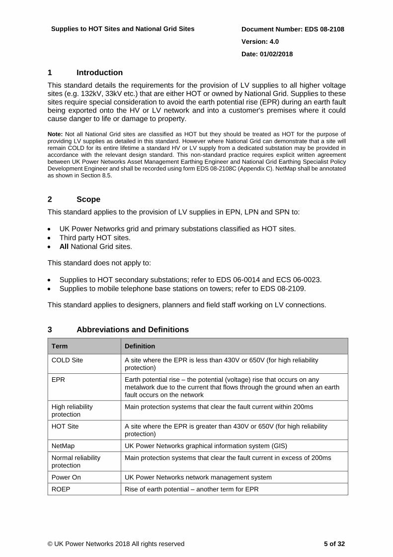
1 Introduction
This standard details the requirements for the provision of LV supplies to all higher voltage sites (e.g. 132kV, 33kV etc.) that are either HOT or owned by National Grid. Supplies to these sites require special consideration to avoid the earth potential rise (EPR) during an earth fault being exported onto the HV or LV network and into a customer's premises where it could cause danger to life or damage to property.
Note: Not all National Grid sites are classified as HOT but they should be treated as HOT for the purpose of
providing LV supplies as detailed in this standard. However where National Grid can demonstrate that a site will remain COLD for its entire lifetime a standard HV or LV supply from a dedicated substation may be provided in accordance with the relevant design standard. This non-standard practice requires explicit written agreement between UK Power Networks Asset Management Earthing Engineer and National Grid Earthing Specialist Policy Development Engineer and shall be recorded using form EDS 08-2108C (Appendix C). NetMap shall be annotated as shown in Section 8.5.
2 Scope
This standard applies to the provision of LV supplies in EPN, LPN and SPN to:
UK Power Networks grid and primary substations classified as HOT sites.
Third party HOT sites.
All National Grid sites.
This standard does not apply to:
Supplies to HOT secondary substations; refer to EDS 06-0014 and ECS 06-0023.
Supplies to mobile telephone base stations on towers; refer to EDS 08-2109.
This standard applies to designers, planners and field staff working on LV connections.
3 Abbreviations and Definitions
Term Definition
COLD Site A site where the EPR is less than 430V or 650V (for high reliability protection)
EPR Earth potential rise – the potential (voltage) rise that occurs on any metalwork due to the current that flows through the ground when an earth fault occurs on the network
High reliability protection
Main protection systems that clear the fault current within 200ms
HOT Site A site where the EPR is greater than 430V or 650V (for high reliability protection)
NetMap UK Power Networks graphical information system (GIS)
Normal reliability protection
Main protection systems that clear the fault current in excess of 200ms
Power On UK Power Networks network management system
ROEP Rise of earth potential – another term for EPR

Supplies to HOT Sites and National Grid Sites Document Number: EDS 08-2108
Version: 4.0
Date: 01/02/2018
© UK Power Networks 2018 All rights reserved 6 of 32
4 Background
4.1 Hot Site
A site is classified as HOT when the earth potential rise (EPR) during an earth fault exceeds 430V or 650V as defined in Table 4-1.
Table 4-1 – EPR Threshold for a HOT Site Classification
Substation Voltage Source Circuit Protection
EPR Comments
400kV, 275kV, 132kV, 66kV, 33kV, 25kV
High reliability 650V Main protection systems that clear the earth fault current within 200ms
Normal reliability 430V Main protection systems that clear the earth fault current in excess of 200ms
20kV, 11kV, 6.6kV Normal reliability 430V Main protection systems that clear the earth fault current in excess of 200ms
4.2 Earth Potential Rise (EPR)
When an earth fault occurs on a cable or at a substation a proportion of the fault current will return to the source substation through the ground. This ‘ground return’ current will flow into the ground through the earth connection(s) closest to the fault; the current flow through the substation earth resistance will cause the voltage of the substation earth connections to rise above that of a remote (or true) earth. This voltage is known as the earth potential rise or EPR.
Note: Some current will flow through the cable screen back to the source and some will flow through the ground,
it is only the current that flows through the ground that causes the EPR.
4.3 Substation Earthing Database
The substation earthing database1 contains the available earthing related data for all grid and primary substations together with a substation classification of HOT or COLD. For further information refer to EDS 06-0002. If a HOT zone plot for an existing UK Power Networks HOT substation is required please contact the document author.
Any relevant information to the connection can be provided by the UK Power Networks Connection Designer if appropriate.
1 UK Power Networks Substation Earthing Database is available from the UK Power Networks Intranet using the following link Substation Earthing Database.

Supplies to HOT Sites and National Grid Sites Document Number: EDS 08-2108
Version: 4.0
Date: 01/02/2018
© UK Power Networks 2018 All rights reserved 7 of 32
5 Process
An overview of the design and implementation process is shown in Figure 5-1. The sections that follow provide further details on each part.
Obtain site information (EPR,
HOT zone etc)
(Section 5.2)
Design secondary substation
using earthing design tool
(EDS 06-0014)
HV
START
Ensure earthing doesn’t
extend outside the HOT zone
END
HV or LV supply?
Customer to provide isolation
transformer*, RCD and earth
(Table 6-1)
LV
Construct substation in
accordance with ECS 06-0023
(Section 7.1)
Isolate HV cable sheaths,
install cables in ducts etc
(Section 7.3)
Apply warning labels
(Section 7.5)
Prepare operational document
(Section 8.2)
Select supply option
(Table 6-1)
Load operational document
into Alfresco
(Section 8.2)
Update NetMap
(Section 8.4)
Prepare SAN showing
HOT Site pins
(Section 8.3)
Apply pins to Power On
(Section 8.3)
Design Delivery Network Records
Apply warning labels
(Section 7.4)
Provide supply from LV
network without an earth
terminal (TT earthing)
Connect substation to main
earthing system of higher
voltage substation
Design supply with TT earth in
accordance with
EDS 08-2100 or EDS 08-2101
(Section 6.2.3)
Review operational document
with Network Manager and
Operational Safety Manager
(Section 8.2)
Link Power On to operational
document in Alfresco
(Section 8.3)
*The isolation transformer is
required to isolate the HOT
site from the UK Power
Networks distribution network
and prevent the EPR being
transferred to other customers.
*The isolation transformer is
required to isolate the HOT
site from the UK Power
Networks distribution network
and prevent the EPR being
transferred to other customers.
Figure 5-1 – Process Flowchart

Supplies to HOT Sites and National Grid Sites Document Number: EDS 08-2108
Version: 4.0
Date: 01/02/2018
© UK Power Networks 2018 All rights reserved 8 of 32
6 Design Requirements
6.1 Information Requirements
The following information, which should be requested from the customer, is required to enable a suitable supply to be designed:
Maximum earth potential rise.
Latest plot of the HOT zone and necessary potential contours.
Other earthing information i.e. soil resistivity, earthing study results, position of buried services/metalwork etc.
6.2 Supply Options
6.2.1 Overview
An overview of various supply options are detailed in Table 6-1 and shown in Figure 6-1. The specific requirements for each option are detailed in the sections that follow.
Table 6-1 – Supply Options Overview
Option Source Description Section
1 Secondary Substation
HOT grid/primary site supply from a dedicated secondary substation inside the HOT zone
6.2.2
2 Dedicated secondary substation outside the HOT zone 6.2.3
3 RMU Outside the HOT Zone and a Transformer Inside the HOT Zone
6.2.4
4 Dedicated secondary substation inside the HOT zone 6.2.5
5 Overhead Line
Dedicated transformer/substation inside HOT Zone 6.2.6
6 Dedicated transformer/substation outside HOT zone 6.2.7
7 LV Network Via isolation transformer 6.2.8

Supplies to HOT Sites and National Grid Sites Document Number: EDS 08-2108
Version: 4.0
Date: 01/02/2018
© UK Power Networks 2018 All rights reserved 9 of 32
LV EarthHV Earth
HOT Grid/Primary Substation
HOT Site
Supplies Only
Normal
Supplies
HV/LV Earth
HV Earth
HOT Site
Metalwork/
LV Earth
HOT Site
HOT Site
Supplies Only
LV EarthHV Earth
HV Overhead
Network
HOT Site
HOT Site
Supplies Only
LV EarthHV Earth
HV Overhead
Network
HOT Site
HOT Site
Supplies Only
HV/LV
Earth
HV Overhead Network
Option 7: LV Network using an Isolation Transformer
HOT Site
LV Earth
LV Network
Isolation TxPole Tx
Pole Tx
HOT Site
Supplies Only
HOT Site
Supplies Only
RMU
RMU
RMU
RMU
HV
Network
HV/LV Earth
HV
Network
Normal
Supplies
Normal
Supplies
HOT Site
HOT Site
Supplies Only
HV/LV
Earth
RMU
RMU
RMU
HV Network
HV Network
HV Network
HV Network
LV Network
HV
NetworkHV/LV
Earth
Option 5: Overhead Line – Dedicated Transformer/
Substation inside HOT Zone
Option 6: Overhead Line – Dedicated Transformer/
Substation Outside HOT Zone
Option 1: HOT Grid/Primary Dedicated Secondary
Substation Inside the HOT Zone
Option 4: Dedicated Secondary Substation Inside the
HOT Zone (ring or tee connection)
Option 2: Dedicated Secondary Substation Outside the
HOT Zone
Option 3: RMU Outside the HOT Zone and a Transformer
Inside the HOT Zone
HV Overhead Network
HV/LV Earth
HOT Site
HOT Site
Supplies Only
RMU
Figure 6-1 – Supply Options Overview
Supplies to HOT Sites and National Grid Sites Document Number: EDS 08-2108
Version: 4.0
Date: 01/02/2018
© UK Power Networks 2018 All rights reserved 10 of 32
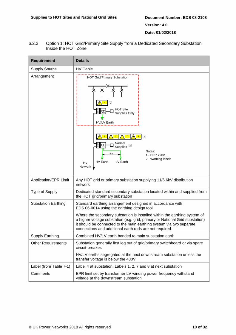
6.2.2 Option 1: HOT Grid/Primary Site Supply from a Dedicated Secondary Substation Inside the HOT Zone
Requirement Details
Supply Source HV Cable
Arrangement
LV EarthHV Earth
8m
HOT Grid/Primary Substation
HOT Site
Supplies Only
Normal
Supplies
HV
Network
HV/LV Earth
Notes:
1 - EPR <2kV
2 - Warning labels
1
1 2
4 2
7
RMU
RMU
28
Application/EPR Limit Any HOT grid or primary substation supplying 11/6.6kV distribution network
Type of Supply Dedicated standard secondary substation located within and supplied from the HOT grid/primary substation
Substation Earthing Standard earthing arrangement designed in accordance with EDS 06-0014 using the earthing design tool
Where the secondary substation is installed within the earthing system of a higher voltage substation (e.g. grid, primary or National Grid substation) it should be connected to the main earthing system via two separate connections and additional earth rods are not required.
Supply Earthing Combined HV/LV earth bonded to main substation earth
Other Requirements Substation generally first leg out of grid/primary switchboard or via spare circuit-breaker.
HV/LV earths segregated at the next downstream substation unless the transfer voltage is below the 430V
Label (from Table 7-1) Label 4 at substation. Labels 1, 2, 7 and 8 at next substation
Comments EPR limit set by transformer LV winding power frequency withstand voltage at the downstream substation

Supplies to HOT Sites and National Grid Sites Document Number: EDS 08-2108
Version: 4.0
Date: 01/02/2018
© UK Power Networks 2018 All rights reserved 11 of 32
6.2.3 Option 2: Dedicated Secondary Substation Outside the HOT Zone
Requirement Details
Supply Source HV Cable
Arrangement
HV
Network
HV
Network
HOT Site
HOT Site
Supplies Only
LV EarthHV Earth
32
Notes:
1 - EPR <2kV
2 – Neutral-earth link removed
3 - LV cable installed in insulated duct
4 - Warning labels
1
4
7
4
4
4
8m
4
RMU
2
1
8
Application/EPR Limit Any HOT site where the EPR is less than 2kV
Type of Supply Dedicated standard secondary substation located outside the HOT zone
Substation Earthing Standard earthing arrangement designed in accordance with EDS 06-0014 using the earthing design tool
Where the secondary substation is installed within the earthing system of a higher voltage substation (e.g. grid, primary or National Grid substation) it should be connected to the main earthing system via two separate connections and additional earth rods are not required.
Supply Earthing Segregated HV/LV earth.
HV earth installed outside the HOT zone and LV earth bonded to HOT site earth
Other Requirements LV cable in insulated duct to preserve insulation integrity.
Neutral-earth link removed and protected by insulated cover
Label (from Table 7-1) Labels 1, 2, 4, 7 and 8 at substation. Label 4 at HOT site
Comments Equivalent to NG TS 3.1.2 Figure 3.
EPR limit set by LV cable sheath power frequency withstand voltage

Supplies to HOT Sites and National Grid Sites Document Number: EDS 08-2108
Version: 4.0
Date: 01/02/2018
© UK Power Networks 2018 All rights reserved 12 of 32
6.2.4 Option 3: RMU Outside the HOT Zone and a Transformer Inside the HOT Zone
Requirement Details
Supply Source HV Cable
Arrangement
HV
Network
HV Earth
HV
Network
HOT Site
Metalwork/
LV Earth
Notes:
1 - EPR <12kV
2 - HV cable sheath insulated at transformer
3 - HV cable installed in insulated duct
4 - Cable length less than 1km
5 - Warning labels
2
3 4
17
HOT Site
Supplies Only
5
5 5
4
6
RMU
Application/EPR Limit Any HOT site where the EPR is less than 12kV
Type of Supply Dedicated secondary substation with the RMU outside the HOT zone and the transformer inside the HOT zone
Note: A variation on this arrangement is to use a metering unit located with the RMU or with the transformer to provide an HV supply
Substation Earthing Standard earthing arrangement designed in accordance with EDS 06-0014 using the earthing design tool
Where the secondary substation is installed within the earthing system of a higher voltage substation (e.g. grid, primary or National Grid substation) it should be connected to the main earthing system via two separate connections and additional earth rods are not required.
Supply Earthing Segregated HV/LV earth
HV RMU earth installed outside the HOT zone. Transformer and LV earth bonded to HOT site earth
Other Requirements HV cable maximum length of 1km
HV cable screen bonded to RMU earth and insulated from the transformer (screen cut back inside cable box and insulated in accordance with 11kV Jointing Manual)
Label (from Table 7-1) Label 7 at substation. Labels 4, 5 and 6 at HOT site
Comments Equivalent to NG TS 3.1.2 Figure 2.
EPR limit set by HV cable sheath power frequency withstand voltage
Cable length to limit induced voltage to 65V due to single-point cable bonding.
Transformer faults should be cleared by the earth fault protection on the ring main unit

Supplies to HOT Sites and National Grid Sites Document Number: EDS 08-2108
Version: 4.0
Date: 01/02/2018
© UK Power Networks 2018 All rights reserved 13 of 32
6.2.5 Option 4: Dedicated Secondary Substation Inside the HOT Zone
6.2.5.1 Option 4a: Dedicated Secondary Substation Inside the HOT Zone – Ring Connection
Requirement Details
Supply Source HV Cable
Arrangement
HV
Network
HV/LV Earth
HV
Network
HV/LV
Earth
Normal
Supplies
Normal
Supplies
HOT Site
Notes:
1 - EPR <5kV
2 - HV cable sheaths bonded
together and insulated from RMU
3 - HV cable installed in insulated
duct in HOT zone
4 - Warning labels
5
4
4
HOT Site
Supplies Only2
7 4
7 4
HV/LV
Earth
See Figure 8
RMU
RMU
RMU
3
3
Application/EPR Limit Any HOT site where the EPR is less than 5kV
Type of Supply Dedicated standard secondary substation located in the HOT zone
Substation Earthing Standard earthing arrangement designed in accordance with EDS 06-0014 using the earthing design tool
Where the secondary substation is installed within the earthing system of a higher voltage substation (e.g. grid, primary or National Grid substation) it should be connected to the main earthing system via two separate connections and additional earth rods are not required.
Supply Earthing Combined HV/LV earth bonded to main site earth
Other Requirements HV cable screens connected together using suitable size bond and insulated at RMU from site earth
HV cable in insulated duct in HOT zone to preserve insulation integrity
Label (from Table 7-1) Label 7 at upstream and downstream substations either side of HOT site. Labels 4 and 5 at HOT site
Comments EPR limit set by the termination method of the bonding between the cable screens.
Note: The power frequency withstand voltage of the HV cable screen is 12kV and the insulated stud is 7kV

Supplies to HOT Sites and National Grid Sites Document Number: EDS 08-2108
Version: 4.0
Date: 01/02/2018
© UK Power Networks 2018 All rights reserved 14 of 32
6.2.5.2 Option 4b: Dedicated Secondary Substation Inside the HOT Zone – Tee Connection
Requirement Details
Supply Source HV Cable
Arrangement
HV
Network
HV/LV Earth
HV
Network
HV/LV
Earth
Normal
Supplies
Normal
Supplies
HOT Site
Notes:
1 - EPR <5kV
2 - HV cable sheaths bonded
together and insulated from RMU
3 - HV cable installed in insulated
duct in HOT zone
4 - Warning labels
5
4
4
HOT Site
Supplies Only
2
7 4
7 4
HV/LV
Earth
RMU
RMU
RMU
3
3
Application/EPR Limit Any HOT site where the EPR is less than 5kV
Type of Supply Dedicated standard secondary substation located in the HOT zone
Substation Earthing Standard earthing arrangement designed in accordance with EDS 06-0014 using the earthing design tool
Where the secondary substation is installed within the earthing system of a higher voltage substation (e.g. grid, primary or National Grid substation) it should be connected to the main earthing system via two separate connections and additional earth rods are not required.
Supply Earthing Combined HV/LV earth bonded to main site earth
Other Requirements HV cable screen insulated at RMU from site earth
HV cable in insulated duct in HOT zone to preserve insulation integrity
Label (from Table 7-1) Label 7 at upstream and downstream substations either side of HOT site. Labels 4 and 5 at HOT site
Comments EPR limit set by the termination method of the bonding between the cable screens.
Note: The power frequency withstand voltage of the HV cable screen is 12kV and the insulated stud is 7kV

Supplies to HOT Sites and National Grid Sites Document Number: EDS 08-2108
Version: 4.0
Date: 01/02/2018
© UK Power Networks 2018 All rights reserved 15 of 32
6.2.6 Option 5: Overhead Line – Dedicated Transformer/Substation Inside HOT Zone
Requirement Details
Supply Source HV Overhead Line
Arrangement
HOT Site
HOT Site
Supplies Only
HV/LV
Earth
HV Overhead
Network
HV Overhead
Network
Pole Tx
Notes:
1 - EPR <12kV
2 - Warning labels
2
1
4
7 2
Application/EPR Limit Any HOT site where the EPR is less than 12kV
Type of Supply Dedicated pole-mounted transformer or ground-mounted substation located inside the HOT zone
Supply Earthing Combined HV/LV earth bonded to main site earth
Other Requirements n/a
Label (from Table 7-1) Label 7 at pole. Label 4 at HOT site
Comments EPR limit set by transformer LV winding and LV cable sheath power frequency withstand voltage

Supplies to HOT Sites and National Grid Sites Document Number: EDS 08-2108
Version: 4.0
Date: 01/02/2018
© UK Power Networks 2018 All rights reserved 16 of 32
6.2.7 Option 6: Overhead Line – Dedicated Transformer/Substation Outside HOT Zone
Requirement Details
Supply Source HV Overhead Line
Arrangement
HV Overhead
Network
HOT Site
HOT Site
Supplies Only
LV EarthHV Earth
HV Overhead
Network
Pole Tx
3
1
2
Notes:
1 - EPR <12kV
2 - Cable installed in insulated duct
3 - Warning labels
8m
4
7 3
Application/EPR Limit Any HOT site where the EPR is less than 12kV
Type of Supply Dedicated pole-mounted transformer or ground-mounted substation located outside the HOT zone
Supply Earthing Segregated HV/LV earth.
HV earth installed outside the HOT zone and LV earth bonded to HOT site earth
Other Requirements n/a
Label (from Table 7-1) Label 7 at pole. Label 4 at HOT site
Comments EPR limit set by transformer LV winding and LV cable sheath power frequency withstand voltage

Supplies to HOT Sites and National Grid Sites Document Number: EDS 08-2108
Version: 4.0
Date: 01/02/2018
© UK Power Networks 2018 All rights reserved 17 of 32
6.2.8 Option 7: LV Network using an Isolation Transformer
Requirement Details
Supply Source LV Network
Arrangement
HOT Site
LV Earth
LV
Network
LV
Network
Isolation TxHOT Site
Supplies Only
1 Notes:
1 - EPR <12kV
2 - Cable installed
in insulated duct
3 - Warning labels
3
2
4
3
Isolation Transformer
Site Earth
RCD
Isolation TransformerRCD
LV Network
Site Earth
Cutout
Cutout
HOT Site
HOT Site
3 43
3 43
Application/EPR Limit Any HOT site where the EPR is less than 2kV
Type of Supply EDS 08-2101 or EDS 08-2100 supply from the LV network via 1:1 Δ-Υ isolation transformer (complying with BS EN 61558-2-4) in the HOT zone
Supply Earthing LV earth bonded to HOT site earth.
Isolation transformer enclosure bonded to site earth
Other Requirements Incoming neutral not connected to isolation transformer enclosure or metalwork. No earth terminal provided (TT earthing)
Isolation transformer protected by RCD
Label (from Table 7-1) Label 3 next to cut-out. Label 4 next to isolation transformer
Comments EPR limit set by LV cable sheath power frequency withstand voltage
For a customer site the boundary shall be at the cut-out and the provision, ownership and maintenance of the isolation transformer , RCD and LV earth is the customers responsibility
Supplies to HOT Sites and National Grid Sites Document Number: EDS 08-2108
Version: 4.0
Date: 01/02/2018
© UK Power Networks 2018 All rights reserved 18 of 32
7 Installation Requirements
7.1 Secondary Substation
The secondary substation earthing system shall be constructed in accordance with ECS 06-0023 paying particular attention to the additional HOT site requirements below:
Installation of HV cable screen bonding or insulation where required in accordance with Section 7.3.2 or Section 7.3.1.
Installation of separate HV and LV earths if required and
Removal of the neutral-earth link.
Removal/disconnection of associated 13A sockets.
Installation of isolation transformer for RTU supply.
Installation of appropriate warning labels (refer to Section 7.5) at both the HOT site and any other associated substations.
If installed within the earthing system of a higher voltage substation (e.g. grid, primary or National Grid) connected to the main earthing system via two separate connections.
7.2 Jointing
Jointing of cables between sites with high EPRs shall be carried out using insulated working practices in accordance with new procedure HSS 40 050 or, in the interim, National Grid instruction NSI 5.
Joints within the HOT zone shall be avoided. 11kV cable is available in 250m drums as standard or 1000m drums by special order.
7.3 HV Cables
7.3.1 Cable Screen – Tee Connection
If the secondary substation is located in the HOT zone and supplied via a tee connection the HV cable screen shall be insulated from the substation earth as follows:
For cables with aluminium wire screen (AWS) do not connect the length of tinned copper braid.
For cables with a copper wire (CWS) terminate the screen in in accordance with the 11kV jointing manual and then cut back, leaving a short tail.
Fully insulate the screen with heat shrink tubing and a heat shrink cap.
Ensure the insulated screen is positioned clear of all earthed metalwork.

Supplies to HOT Sites and National Grid Sites Document Number: EDS 08-2108
Version: 4.0
Date: 01/02/2018
© UK Power Networks 2018 All rights reserved 19 of 32
7.3.2 Cable Screen – Ring Connection
If the secondary substation is located in the HOT zone and supplied via a ring connection the HV cable screens shall be bonded together and insulated from the substation earth as shown in Figure 7-1 and Figure 7-2.
SW2 (RH) Cable Box
RMU
SW1 (LH) Cable Box
Aluminium or Copper Insulated Cable Sheath
Bond Sized to match Earthing System
Insulated Earth
Stud Removed
and Blanked Off
Heat Shrink
Boot
Connector
03196H or
MF15/5/SH
from 02806D
Cable Sheaths Insulated
from Cable Boxes
Cover
Connector with
Heat Shrink
Figure 7-1 – RMU Cable Screen Bonding
Figure 7-2 – RMU Cable Copper Wire Screen Bonding
For cables with an aluminium wire screen (AWS) terminate the screens using lug 02236J and the earth cable using connector 02236J. Bolt the two lugs together (Figure 7-3). Alternatively connector 04523C may be used.
For cables with a copper wire screen (CWS) terminate the screens and earth cable using connector 03196H (Figure 7-4).
Fully insulate the screen with heat shrink tubing and a heat shrink cap.
Ensure the insulated screen is positioned clear of all earthed metalwork.

Supplies to HOT Sites and National Grid Sites Document Number: EDS 08-2108
Version: 4.0
Date: 01/02/2018
© UK Power Networks 2018 All rights reserved 20 of 32
Figure 7-3 – Ring Connection Cable Screen Bonding – Aluminium Wire Screen
Figure 7-4 – Ring Connection Screen Cable Bonding – Copper Wire Screen
7.3.3 Lead Sheathed Cables
If lead sheathed (PILC) cables are connected to the HOT site they will export the EPR and therefore they shall be replaced with insulated sheathed cables within the HOT zone and five metres outside it.
7.4 Miscellaneous Materials
Application Material Code or Reference
Description Comments
11kV Cable Duct EAS 00-0002 Ducts and duct accessories Use 33kV ducts from Emtelle
LV Duct EAS 00-0002 Ducts and duct accessories
Cable Screen Bonding (AWS)
02356J Lug Aluminium Cable 300mm M16
02236J Mechanical Lug 70 to 120mm (10/12mm Hole)
04523C LV Plant Termination Kit S/C Cables
Cable Screen Bonding (CWS)
03196H Connector Straight Thru Main 300

Supplies to HOT Sites and National Grid Sites Document Number: EDS 08-2108
Version: 4.0
Date: 01/02/2018
© UK Power Networks 2018 All rights reserved 21 of 32
7.5 Warning Labels
The warning labels detailed Table 7-1 shall be installed as specified in Section 6.2. as most labels are of the adhesive type where they are to be used on a pole they should be affixed to suitable backing plate that can be fixed to the pole.
Table 7-1 – Warning Labels
No Situation/Location Reference2 (Material Code3)
Specification Label
1 Install in prominent position inside fence/enclosure
EDS 07-0009.117
(21515D)
100mm x 150mm adhesive label
2 In LV cabinet or micro/compact
EDS 07-0009.118
(21655V)
100mm x 50mm adhesive label
3 Next to the cut-out EDS 07-0009.121
(21657Q)
100mm x 25mm adhesive label
Next to the cut-out EDS 07-0009.178
(21691R)
100mm x 25mm adhesive label
4 Next to the cut-out and pole transformer
EDS 07-0009.131
(21649B)
100mm x 37.5mm adhesive label
5 Next to affected equipment
EDS 07-0009.132
(21650W)
100mm x 37.5mm adhesive label
6 On substation door EDS 07-0009.133
(21651G)
100mm x 50mm adhesive label
2 For the availability of labels without a material code please contact the author or refer to EAS 07-0021. 3 UK Power Networks logistics material code.

Supplies to HOT Sites and National Grid Sites Document Number: EDS 08-2108
Version: 4.0
Date: 01/02/2018
© UK Power Networks 2018 All rights reserved 22 of 32
No Situation/Location Reference2 (Material Code3)
Specification Label
7 On substation door EDS 07-0009.134
(21652R)
100mm x 50mm adhesive label
8 In LV cabinet or micro/compact
EDS 07-0009.171
(21517X)
75mm x 110mm adhesive label

Supplies to HOT Sites and National Grid Sites Document Number: EDS 08-2108
Version: 4.0
Date: 01/02/2018
© UK Power Networks 2018 All rights reserved 23 of 32
8 Operational Requirements
8.1 General
Any installation that involves different earthing systems which are not bonded together carries a level of risk should simultaneous contact occur between the two systems. Special care is needed when working on circuits or switchgear where access to the different earthing systems may be made possible. The main issues are:
Applying a circuit main earth at the HOT site or adjacent sites.
Working on cables between different earthing systems.
Insulated working should be considered where applicable, refer to HSS 40 050 for further information.
It is therefore important that the switchgear maintenance and cable working requirements are considered at the design stage.
8.2 Documentation
It is the joint responsibility of the senior authorised person, with the assistance of the designer and/or project manager, to determine any special operating arrangements and prepare an operational requirements document. An example document is included in Appendix B. The document shall be added to Alfresco and linked to the Power On HOT Site pin detailed in Section 8.3.
Any special operating arrangements should be approved by the Operational Safety Manager and the Control/Network Manager.
8.3 Power On
A HOT site pin shall be applied on the Power On diagram at each affected site to highlight any non-standard earthing requirements. The HOT site dressing pins shall be applied as below:
At the HOT site – on the circuit-breaker of all ring main units on site.
At sites either side of HOT site – on the substation circuit-breaker or ring main unit switch
An example is shown in Figure 8-1 both ‘Action Ln Opp Waxlow Rd National Grid’ (the HOT site with non-standard earthing) and the sites either side have HOT Site pins. Examples of the HOT Site pin text are shown in Table 8-1.
Table 8-1 – Power On HOT Site Pin Text
HOT Site
This substation provides a supply to a HOT site and has a non-standard earthing arrangement and/or insulated cable screens.
Refer to the attached site specific operating instructions for further information.
This substation shall not be used to provide LV supplies to other customers.
Warning Connected to a HOT Site
This substation is connected to a HOT site with a non-standard earthing arrangement and/or insulated cable screens.
Refer to the attached site specific operating instructions for further information.

Supplies to HOT Sites and National Grid Sites Document Number: EDS 08-2108
Version: 4.0
Date: 01/02/2018
© UK Power Networks 2018 All rights reserved 24 of 32
The relevant information should be included on the System Alteration Notice (SAN) to allow the diagram to be correctly annotated.
Figure 8-1 – Power On HOT Site Annotation
8.4 NetMap
On completion of the installation NetMap shall be updated to show:
That the substation cannot be used to provide LV supplies to other customers as shown in Table 8-2.
Insulated cable screens.
Sections of overhead line that should not be undergrounded.
Any other bespoke installation details.
Table 8-2 – NetMap HOT Site Label
HOT Site Supply
This substation shall not be used to provide LV supplies to other customers

Supplies to HOT Sites and National Grid Sites Document Number: EDS 08-2108
Version: 4.0
Date: 01/02/2018
© UK Power Networks 2018 All rights reserved 25 of 32
8.5 National Grid Site
Generally all National Grid sites are treated as HOT and shall be annotated on PowerOn and NetMap as detailed in Section 8.3 and 8.4. However where it has been agreed between UK Power Networks and National Grid that the site is to be classified as COLD NetMap shall be annotated as shown in Table 8-3.
Table 8-3 – NetMap National Grid Label
National Grid Dedicated Site Supply
This substation shall not be used to provide LV supplies to other customers

Supplies to HOT Sites and National Grid Sites Document Number: EDS 08-2108
Version: 4.0
Date: 01/02/2018
© UK Power Networks 2018 All rights reserved 26 of 32
9 References
9.1 UK Power Networks Standards
EAS 02-0000 Approved Equipment List - Cables and Joints
ECS 02-0011 11kV Jointing Manual
EDS 06-0002 HOT Site Management (internal document only)
EDS 06-0014 Secondary Substation Earthing Design
EDS 06-0017 Customer Installation Earthing Design
ECS 06-0023 Secondary Distribution Network Earthing Construction
EAS 07-0021 Signs and Labels for Operational Sites
EDS 08-2100 LV Customer Supplies
EDS 08-2101 LV Customer Supplies up to 100A Single-phase
EDS 08-2109 LV supplies to Mobile Phone Base Stations Mounted on 132, 275 and 400kV Towers (internal document only)
HSS 40 050 Controlling Impressed Voltages on Underground Cable Systems (future HSS document)
9.2 National Standards
National Grid TS 3.1.2 Earthing
National Grid NSI 5 Insulated Working on Cable Systems
10 Dependent Documents
EDS 06-0002 HOT Site Management (internal document only)
EDS 06-0017 Customer Installation Earthing Design
EDS 06-0019 Customer EHV and HV Connections (including Generation) Earthing Design and Construction Guidelines
ECS 06-0022 Grid and Primary Earthing Construction
EAS 07-0021 Signs and Labels for Operational Sites
EDS 07-1119 Substation Electrical Services
EDS 08-0149 Customer Supply Interface
EDS 08-1112 LVAC Supplies
EDS 08-2100 LV Customer Supplies

Supplies to HOT Sites and National Grid Sites Document Number: EDS 08-2108
Version: 4.0
Date: 01/02/2018
© UK Power Networks 2018 All rights reserved 27 of 32
Appendix A – Examples
A.1 National Grid Acton Lane 22kV
Acton Lane consists of 22kV National Grid substation as shown in Figure A-1. Although Acton Lane is not currently classified as a HOT site all supplies to National Grid sites have to be treated as HOT to cater for future changes to the network or an increase in fault level. An LV supply was requested by National Grid and provided from a secondary substation using option 4 (Section 6.2.5) as shown in Figure A-2.
Figure A-1 – LV Supply to National Grid 22kV Substation at Acton Lane
24843
Acton Ln Opp Waxlow Rd
National Grid
24650
Acton Lne Hamm
Med Res
24731
Waxlow Rd Unit A
Centrus
240
Gibbons Road
SW1
Panel 48
HOT
Site
Figure A-2 – LV Supply to National Grid 22kV Substation at Acton Lane

Supplies to HOT Sites and National Grid Sites Document Number: EDS 08-2108
Version: 4.0
Date: 01/02/2018
© UK Power Networks 2018 All rights reserved 28 of 32
A.2 Rayleigh Main
Rayleigh Main consists of a 400kV National Grid substation and a UK Power Networks 132kV substation. Rayleigh Main is HOT with a maximum EPR of 1777V for a fault on the 400kV network. The substations are shown in Figure A-3 and the supply arrangement is shown in Figure A-4.
Figure A-3 – Rayleigh 400kV and 132kV Substations
Figure A-4 – Rayleigh 400kV and 132kV Substations – Power On Extract
Rayleigh Main 132kV
Rayleigh Main 400kV
NG Switching Station 11kV
Rayleigh GIS Local and Local 2 11kV
CEGB 400 Grid11kV

Supplies to HOT Sites and National Grid Sites Document Number: EDS 08-2108
Version: 4.0
Date: 01/02/2018
© UK Power Networks 2018 All rights reserved 29 of 32
A.2.1 Rayleigh Main 400kV via NG Switching Station
NG Switching Station is a new secondary substation containing a ring main unit without a transformer. During the design and construction of this substation the switchgear at the CEGB substation located within Rayleigh Main 400kV was solidly bonded to the Rayleigh Main 400kV earth grid.
The 11kV cable that feeds into the CEGB substation was of PILC construction and the cable sheath was therefore not insulated from the soil. To separate the earthing the PILC cable was overlaid with plastic sheathed cable. The cable screen was insulated from the site earth in the CEGB substation. This is an example of Option 3 (Section 6.2.4).
A.2.2 Rayleigh Main 132kV Supply via Rayleigh GIS Local and Rayleigh GIS Local 2
Rayleigh Main 132kV has two disparate 400V three-phase supplies. Each is supplied from a separate secondary substation located 3m outside the Rayleigh Main 132kV substation fence. The secondary substations each have an independent earthing system but they are bonded together; however neither is bonded to the Rayleigh Main 132kV earth grid. The three-phase 400V supply from each of the secondary substations is bonded to the Rayleigh Main 132kV substation earth grid at the LVAC distribution board. At each secondary substation the LV neutral has been disconnected from the substation earth. This is where the rise of potential will occur during fault conditions. A label has been applied to draw attention to the arrangement. The power socket in the distribution substation has also been disconnected.
This arrangement prevents the earth potential rise occurring during a 400kV fault at Rayleigh Main 400kV from being exported onto the 11kV earthing system. It also prevents other customers from being supplied from this substation as any 400V connections would be bonded to HOT substation earth grid. This is an example of Option 2 (Section 6.2.3).

Supplies to HOT Sites and National Grid Sites Document Number: EDS 08-2108
Version: 4.0
Date: 01/02/2018
© UK Power Networks 2018 All rights reserved 30 of 32
A.3 Norwich Main
Norwich Main consists of a 400kV National Grid substation and a UK Power Networks 132kV substation as shown in Figure A-5. Norwich Main is HOT with a maximum EPR of 2650V for a fault on the 400kV network. A dual LV supply was requested by National Grid for the 400kV substation and a single LV supply was required for the 132kV substation.
The supplies were provided using option 4 (Section 6.2.5) from overhead line on one side and cable on the other as shown in Figure A-6.
Figure A-5 – Norwich Main 400kV and 132kV Substations
Norwich Main
400kV
Norwich Main
132kV
Norwich Main
132kV Local B
Pole 8 Pole 7
HV/LV Earth
HOT Site
Supply
Orange Mast
Ipswich Road
Normal
Supply
Pole 11APole 12 Pole 11
CableOHL
Norwich – London Liverpool St Main Line
HOT Zone
HV/LV Earth
Norwich Main
Dunston
HV/LV Earth
HOT Site
Supply 2
HOT Site
Supply 1
HV Earth
HV Earth
Figure A-6 – LV Supply to Norwich Main 400kV and 132kV Substations
Norwich Main 400kV
Norwich Main 132kV
Supplies to HOT Sites and National Grid Sites Document Number: EDS 08-2108
Version: 4.0
Date: 01/02/2018
© UK Power Networks 2018 All rights reserved 31 of 32
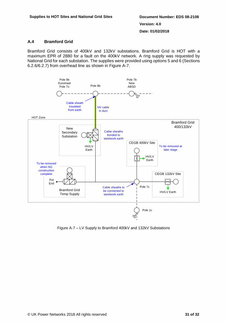
A.4 Bramford Grid
Bramford Grid consists of 400kV and 132kV substations. Bramford Grid is HOT with a maximum EPR of 2880 for a fault on the 400kV network. A ring supply was requested by National Grid for each substation. The supplies were provided using options 5 and 6 (Sections 6.2.6/6.2.7) from overhead line as shown in Figure A-7.
Pole 8b
Pole 7b
New
ABSD
HOT Zone
HV/LV
Earth
New
Secondary
Substation
Pole 9b
Euromast
Pole Tx
Pole 7c
Pole 1c
CEGB 400kV Site
CEGB 132kV Site
Bramford Grid
Temp SupplyHV/LV Earth
HV/LV
Earth
Pot
End
HV cable
in duct
Cable sheath
insulated
from earth
Cable sheaths
bonded to
steelwork earth
Bramford Grid
400/132kV
To be removed
when NG
construction
complete
To be removed at
later stage
Cable sheaths to
be connected to
steelwork earth
Figure A-7 – LV Supply to Bramford 400kV and 132kV Substations

Supplies to HOT Sites and National Grid Sites Document Number: EDS 08-2108
Version: 4.0
Date: 01/02/2018
© UK Power Networks 2018 All rights reserved 32 of 32
Appendix B – Operational Document
An example operational document for the Acton Lane example in Appendix A is available as a separate document EDS 08-2108B.
Appendix C – National Grid COLD Site Form
Form EDS 08-2108C register the classification of a National Grid substation as a COLD site for the purpose of providing an LV supply.