Embed Size (px)
Citation preview
MOVIDRIVE® compact MCH4_AEdition
04/2002
Operating Instructions1054 7916 / EN

SEW-EURODRIVE
MOVIDRIVE® compact MCH4_A Operating Instructions 3
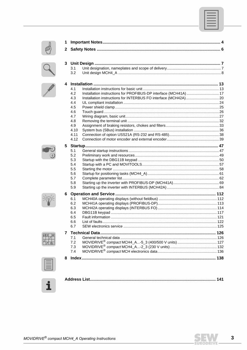
1 Important Notes...................................................................................................... 4
2 Safety Notes ........................................................................................................... 6
3 Unit Design ............................................................................................................. 73.1 Unit designation, nameplates and scope of delivery.................................................... 73.2 Unit design MCH4_A ................................................................................................... 8
4 Installation ............................................................................................................ 134.1 Installation instructions for basic unit ......................................................................... 134.2 Installation instructions for PROFIBUS-DP interface (MCH41A) ............................... 174.3 Installation instructions for INTERBUS FO interface (MCH42A)................................ 204.4 UL compliant installation ............................................................................................ 244.5 Power shield clamp.................................................................................................... 254.6 Touch guard............................................................................................................... 264.7 Wiring diagram, basic unit.......................................................................................... 274.8 Removing the terminal unit ........................................................................................ 324.9 Assignment of braking resistors, chokes and filters ................................................... 334.10 System bus (SBus) installation .................................................................................. 364.11 Connection of option USS21A (RS-232 and RS-485)................................................ 384.12 Connection of motor encoder and external encoder .................................................. 39
5 Startup................................................................................................................... 475.1 General startup instructions ....................................................................................... 475.2 Preliminary work and resources................................................................................. 495.3 Startup with the DBG11B keypad .............................................................................. 505.4 Startup with a PC and MOVITOOLS.......................................................................... 575.5 Starting the motor ...................................................................................................... 585.6 Startup for positioning tasks (MCH4_A)..................................................................... 615.7 Complete parameter list ............................................................................................. 625.8 Starting up the inverter with PROFIBUS-DP (MCH41A)............................................ 695.9 Starting up the inverter with INTERBUS (MCH42A) .................................................. 84
6 Operation and Service ....................................................................................... 1126.1 MCH40A operating displays (without fieldbus) ........................................................ 1126.2 MCH41A operating displays (PROFIBUS-DP)......................................................... 1136.3 MCH42A operating displays (INTERBUS FO) ......................................................... 1146.4 DBG11B keypad ...................................................................................................... 1176.5 Fault information ...................................................................................................... 1216.6 List of faults .............................................................................................................. 1226.7 SEW electronics service .......................................................................................... 125
7 Technical Data.................................................................................................... 1267.1 General technical data ............................................................................................. 1267.2 MOVIDRIVE® compact MCH4_A...-5_3 (400/500 V units) ...................................... 1277.3 MOVIDRIVE® compact MCH4_A...-2_3 (230 V units) ............................................. 1327.4 MOVIDRIVE® compact MCH electronics data......................................................... 136
8 Index.................................................................................................................... 138
Address List............................................................................................................. 141
00
I
Pi
fkVA
Hz
n
1
4 MOVIDRIVE® compact MCH4_A Operating Instructions
1 Important Notes
Safety and warn-
ing instructions
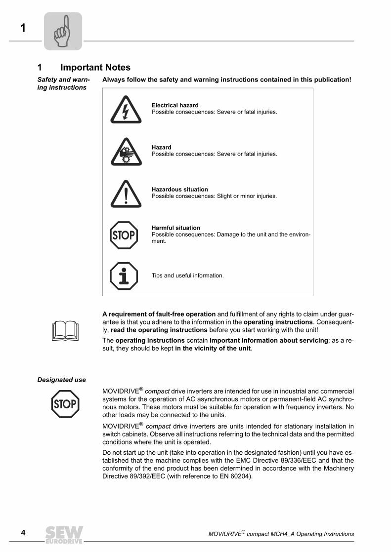
Always follow the safety and warning instructions contained in this publication!
A requirement of fault-free operation and fulfillment of any rights to claim under guar-
antee is that you adhere to the information in the operating instructions. Consequent-
ly, read the operating instructions before you start working with the unit!
The operating instructions contain important information about servicing; as a re-
sult, they should be kept in the vicinity of the unit.
Designated use
MOVIDRIVE® compact drive inverters are units intended for stationary installation in
switch cabinets. Observe all instructions referring to the technical data and the permitted
conditions where the unit is operated.
Do not start up the unit (take into operation in the designated fashion) until you have es-
tablished that the machine complies with the EMC Directive 89/336/EEC and that the
conformity of the end product has been determined in accordance with the Machinery
Directive 89/392/EEC (with reference to EN 60204).
Electrical hazard
Possible consequences: Severe or fatal injuries.
Hazard
Possible consequences: Severe or fatal injuries.
Hazardous situation
Possible consequences: Slight or minor injuries.
Harmful situation
Possible consequences: Damage to the unit and the environ-ment.
Tips and useful information.
MOVIDRIVE® compact drive inverters are intended for use in industrial and commercial
systems for the operation of AC asynchronous motors or permanent-field AC synchro-
nous motors. These motors must be suitable for operation with frequency inverters. No
other loads may be connected to the units.
MOVIDRIVE® compact MCH4_A Operating Instructions 5
1
Application envi-
ronment
The following uses are forbidden unless measures are expressly taken to make
them possible:
Safety functions
Waste disposal Please follow the current instructions: Dispose in accordance with the material structure
and the regulations in force, for instance as:
• Electronics scrap (printed-circuit boards)
• Plastic (housing)
• Sheet metal
• Copper
etc.
• Use in explosion-proof areas
• Use in areas exposed to harmful oils, acids, gases, vapors, dust, radiation, etc.
• Use in non-stationary applications which are subject to mechanical vibration and
shock loads in excess of the requirement in EN 50178
MOVIDRIVE® compact drive inverters are not allowed to perform any safety functions
unless the inverters are monitored by other safety systems.
Use superordinate safety systems to guarantee the protection of machinery and people.
2
6 MOVIDRIVE® compact MCH4_A Operating Instructions
2 Safety Notes
Installation and
startup
• Never install damaged products or take them into operation. Please submit a
complaint to the shipping company immediately in the event of damage.
• Installation, startup and service work may only be performed by trained person-
nel observing applicable accident prevention regulations and operating instructions!
The regulations in force (e.g. EN 60204, VBG 4, DIN-VDE 0100/0113/0160) must
also be complied with.
• Follow the specific instructions during installation and startup of the motor and
the brake!
• The unit meets all requirements for reliable isolation of power and electronics
connections in accordance with EN 50178. All connected circuits must also satisfy
the requirements for reliable isolation so as to guarantee reliable isolation.
• Take suitable measures to ensure that the connected motor does not start up au-
tomatically when the inverter is switched on.
Suitable measures are:
– With MCF/MCV/MCS4_A: Connect terminal X10:9 '/CONTROL. INHIBIT' to
DGND.
– With MCH4_A: Disconnect the electronics terminal block X11.
Operation and
service
• Disconnect the unit from the power supply system prior to removing the pro-
tective cover. Dangerous voltages may still be present for up to 10 minutes after
mains disconnection.
• Dangerous voltages are present at the output terminals and the cables and mo-
tor terminals connected to them when the unit is switched on. This also applies
even when the unit is inhibited and the motor at a standstill.
• Just because the operation LED and other display elements have gone out does
not mean that the unit has been disconnected from the supply system and is de-en-
ergized.
• Switch the inverter output only when the output stage is inhibited.
• Make sure that preventive measures and protection devices correspond to the
applicable regulations (e.g. EN 60204 or EN 50178).
Necessary protection measures: Grounding the unit
Necessary protection device: Overcurrent protection devices
• The unit has IP 00 enclosure with the protective cover removed. Dangerous volt-
ages are present at all subassemblies except for the control electronics. The unit
must be closed during operation.
• Safety functions inside the unit or a mechanical blockage may cause the motor
to stop. The removal of the source of the malfunction or a reset can result in an
automatic restart of the drive. If, for safety reasons, this is not permitted for the
driven machine, the unit must be disconnected from the supply system before
correcting the fault. In such cases, it is also forbidden for the 'Auto reset' function
(P841) to be activated.
MOVIDRIVE® compact MCH4_A Operating Instructions 7
3Unit designation, nameplates and scope of delivery
3 Unit Design
3.1 Unit designation, nameplates and scope of delivery
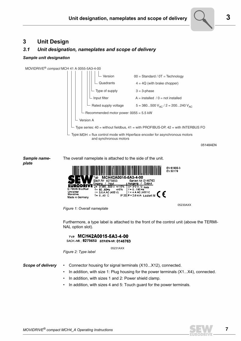
Sample unit designation
Sample name-
plate
The overall nameplate is attached to the side of the unit.
Furthermore, a type label is attached to the front of the control unit (above the TERMI-
NAL option slot).
Scope of delivery • Connector housing for signal terminals (X10...X12), connected.
• In addition, with size 1: Plug housing for the power terminals (X1...X4), connected.
• In addition, with sizes 1 and 2: Power shield clamp.
• In addition, with sizes 4 and 5: Touch guard for the power terminals.
05148AEN
05230AXX
Figure 1: Overall nameplate
05231AXX
Figure 2: Type label
3
8 MOVIDRIVE® compact MCH4_A Operating Instructions
Unit design MCH4_A
3.2 Unit design MCH4_A
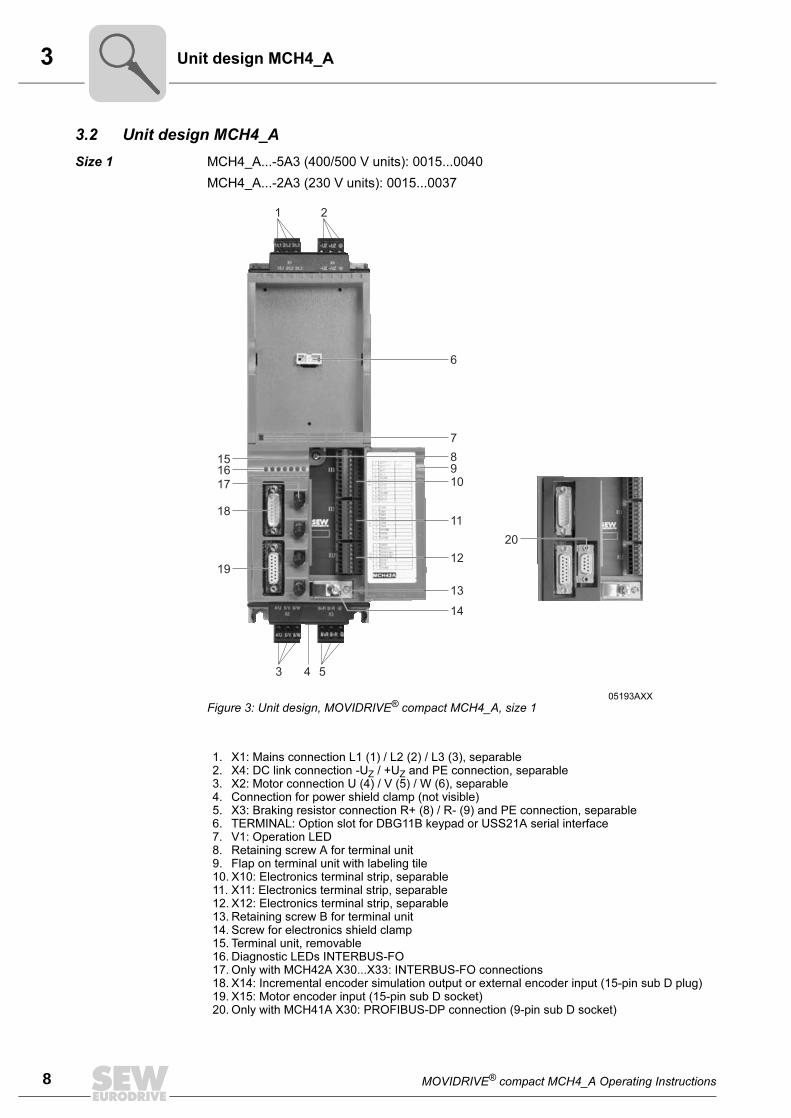
Size 1 MCH4_A...-5A3 (400/500 V units): 0015...0040
MCH4_A...-2A3 (230 V units): 0015...0037
05193AXX
Figure 3: Unit design, MOVIDRIVE® compact MCH4_A, size 1
1. X1: Mains connection L1 (1) / L2 (2) / L3 (3), separable2. X4: DC link connection -UZ / +UZ and PE connection, separable3. X2: Motor connection U (4) / V (5) / W (6), separable4. Connection for power shield clamp (not visible)5. X3: Braking resistor connection R+ (8) / R- (9) and PE connection, separable6. TERMINAL: Option slot for DBG11B keypad or USS21A serial interface7. V1: Operation LED8. Retaining screw A for terminal unit9. Flap on terminal unit with labeling tile10. X10: Electronics terminal strip, separable11. X11: Electronics terminal strip, separable12. X12: Electronics terminal strip, separable13. Retaining screw B for terminal unit14. Screw for electronics shield clamp15. Terminal unit, removable16. Diagnostic LEDs INTERBUS-FO17. Only with MCH42A X30...X33: INTERBUS-FO connections18. X14: Incremental encoder simulation output or external encoder input (15-pin sub D plug)19. X15: Motor encoder input (15-pin sub D socket)20. Only with MCH41A X30: PROFIBUS-DP connection (9-pin sub D socket)
MOVIDRIVE® compact MCH4_A Operating Instructions 9
3Unit design MCH4_A
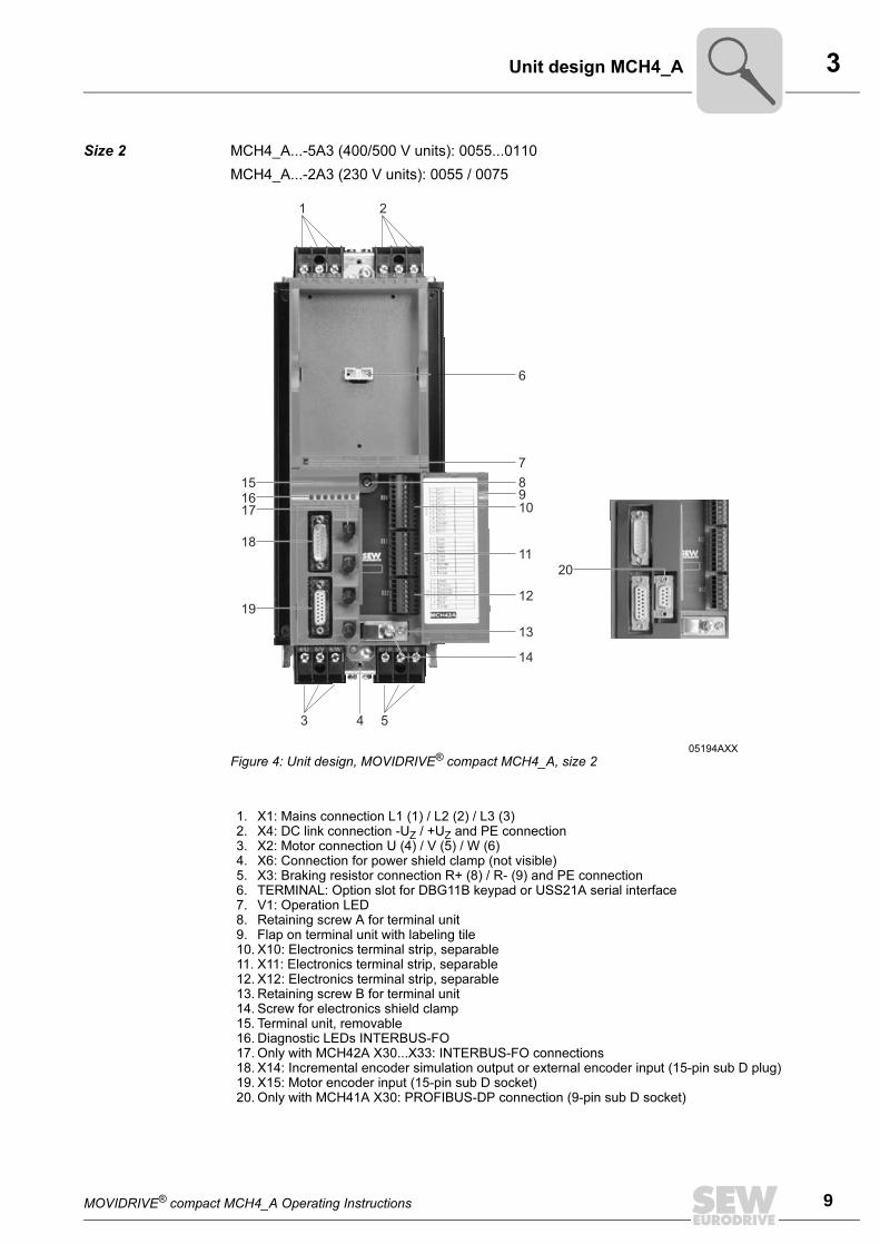
Size 2 MCH4_A...-5A3 (400/500 V units): 0055...0110
MCH4_A...-2A3 (230 V units): 0055 / 0075
05194AXX
Figure 4: Unit design, MOVIDRIVE® compact MCH4_A, size 2
1. X1: Mains connection L1 (1) / L2 (2) / L3 (3)2. X4: DC link connection -UZ / +UZ and PE connection3. X2: Motor connection U (4) / V (5) / W (6)4. X6: Connection for power shield clamp (not visible)5. X3: Braking resistor connection R+ (8) / R- (9) and PE connection6. TERMINAL: Option slot for DBG11B keypad or USS21A serial interface7. V1: Operation LED8. Retaining screw A for terminal unit9. Flap on terminal unit with labeling tile10. X10: Electronics terminal strip, separable11. X11: Electronics terminal strip, separable12. X12: Electronics terminal strip, separable13. Retaining screw B for terminal unit14. Screw for electronics shield clamp15. Terminal unit, removable16. Diagnostic LEDs INTERBUS-FO17. Only with MCH42A X30...X33: INTERBUS-FO connections18. X14: Incremental encoder simulation output or external encoder input (15-pin sub D plug)19. X15: Motor encoder input (15-pin sub D socket)20. Only with MCH41A X30: PROFIBUS-DP connection (9-pin sub D socket)
3
10 MOVIDRIVE® compact MCH4_A Operating Instructions
Unit design MCH4_A
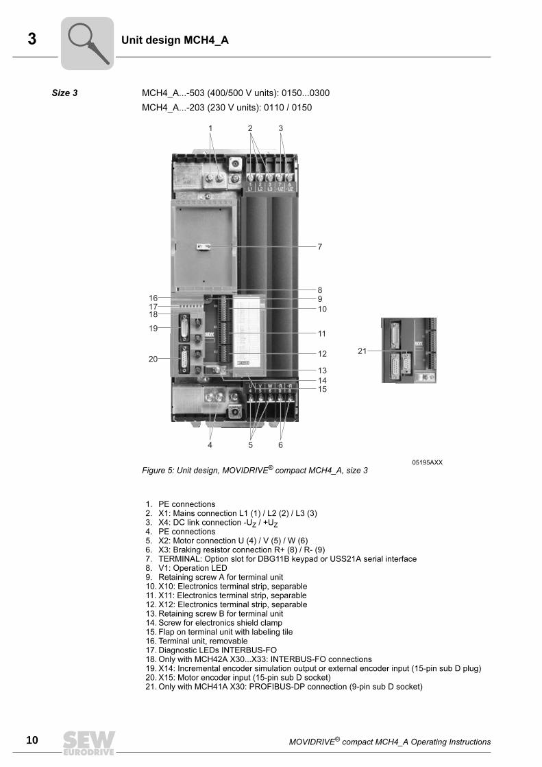
Size 3 MCH4_A...-503 (400/500 V units): 0150...0300
MCH4_A...-203 (230 V units): 0110 / 0150
05195AXX
Figure 5: Unit design, MOVIDRIVE® compact MCH4_A, size 3
1. PE connections2. X1: Mains connection L1 (1) / L2 (2) / L3 (3)3. X4: DC link connection -UZ / +UZ
4. PE connections5. X2: Motor connection U (4) / V (5) / W (6)6. X3: Braking resistor connection R+ (8) / R- (9)7. TERMINAL: Option slot for DBG11B keypad or USS21A serial interface8. V1: Operation LED9. Retaining screw A for terminal unit10. X10: Electronics terminal strip, separable11. X11: Electronics terminal strip, separable12. X12: Electronics terminal strip, separable13. Retaining screw B for terminal unit14. Screw for electronics shield clamp15. Flap on terminal unit with labeling tile16. Terminal unit, removable17. Diagnostic LEDs INTERBUS-FO18. Only with MCH42A X30...X33: INTERBUS-FO connections19. X14: Incremental encoder simulation output or external encoder input (15-pin sub D plug)20. X15: Motor encoder input (15-pin sub D socket)21. Only with MCH41A X30: PROFIBUS-DP connection (9-pin sub D socket)
MOVIDRIVE® compact MCH4_A Operating Instructions 11
3Unit design MCH4_A
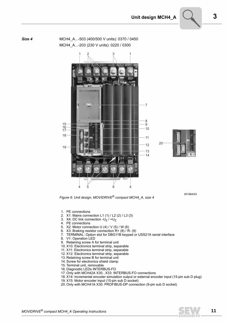
Size 4 MCH4_A...-503 (400/500 V units): 0370 / 0450
MCH4_A...-203 (230 V units): 0220 / 0300
05196AXX
Figure 6: Unit design, MOVIDRIVE® compact MCH4_A, size 4
1. PE connections2. X1: Mains connection L1 (1) / L2 (2) / L3 (3)3. X4: DC link connection -UZ / +UZ
4. PE connections5. X2: Motor connection U (4) / V (5) / W (6)6. X3: Braking resistor connection R+ (8) / R- (9)7. TERMINAL: Option slot for DBG11B keypad or USS21A serial interface8. V1: Operation LED9. Retaining screw A for terminal unit10. X10: Electronics terminal strip, separable11. X11: Electronics terminal strip, separable12. X12: Electronics terminal strip, separable13. Retaining screw B for terminal unit14. Screw for electronics shield clamp15. Terminal unit, removable16. Diagnostic LEDs INTERBUS-FO17. Only with MCH42A X30...X33: INTERBUS-FO connections18. X14: Incremental encoder simulation output or external encoder input (15-pin sub D plug)19. X15: Motor encoder input (15-pin sub D socket)20. Only with MCH41A X30: PROFIBUS-DP connection (9-pin sub D socket)
3
12 MOVIDRIVE® compact MCH4_A Operating Instructions
Unit design MCH4_A
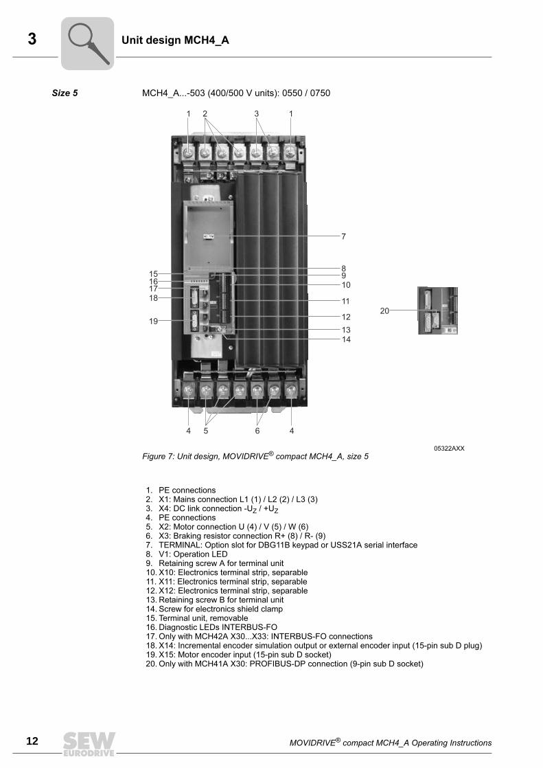
Size 5 MCH4_A...-503 (400/500 V units): 0550 / 0750
05322AXX
Figure 7: Unit design, MOVIDRIVE® compact MCH4_A, size 5
1. PE connections2. X1: Mains connection L1 (1) / L2 (2) / L3 (3)3. X4: DC link connection -UZ / +UZ
4. PE connections5. X2: Motor connection U (4) / V (5) / W (6)6. X3: Braking resistor connection R+ (8) / R- (9)7. TERMINAL: Option slot for DBG11B keypad or USS21A serial interface8. V1: Operation LED9. Retaining screw A for terminal unit10. X10: Electronics terminal strip, separable11. X11: Electronics terminal strip, separable12. X12: Electronics terminal strip, separable13. Retaining screw B for terminal unit14. Screw for electronics shield clamp15. Terminal unit, removable16. Diagnostic LEDs INTERBUS-FO17. Only with MCH42A X30...X33: INTERBUS-FO connections18. X14: Incremental encoder simulation output or external encoder input (15-pin sub D plug)19. X15: Motor encoder input (15-pin sub D socket)20. Only with MCH41A X30: PROFIBUS-DP connection (9-pin sub D socket)
MOVIDRIVE® compact MCH4_A Operating Instructions 13
4Installation instructions for basic unit
4 Installation
4.1 Installation instructions for basic unit
Tightening
torques
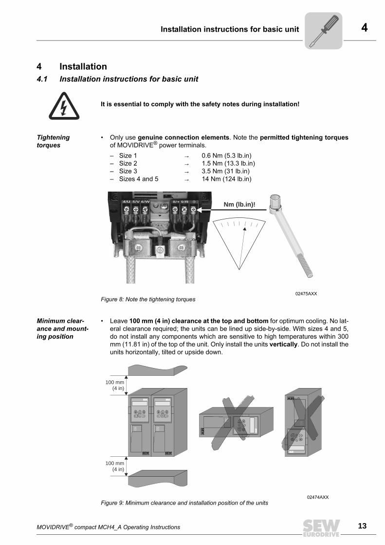
• Only use genuine connection elements. Note the permitted tightening torques
of MOVIDRIVE® power terminals.
– Size 1 → 0.6 Nm (5.3 lb.in)
– Size 2 → 1.5 Nm (13.3 lb.in)
– Size 3 → 3.5 Nm (31 lb.in)
– Sizes 4 and 5 → 14 Nm (124 lb.in)
Minimum clear-
ance and mount-
ing position
• Leave 100 mm (4 in) clearance at the top and bottom for optimum cooling. No lat-
eral clearance required; the units can be lined up side-by-side. With sizes 4 and 5,
do not install any components which are sensitive to high temperatures within 300
mm (11.81 in) of the top of the unit. Only install the units vertically. Do not install the
units horizontally, tilted or upside down.
It is essential to comply with the safety notes during installation!
02475AXX
Figure 8: Note the tightening torques
Nm (lb.in)!
02474AXX
Figure 9: Minimum clearance and installation position of the units
E Q E QQ
EQQ
100 mm(4 in)
100 mm(4 in)
EQQ
EQQ
EQQ
4
14 MOVIDRIVE® compact MCH4_A Operating Instructions
Installation instructions for basic unit
Separate cable
ducts
• Route power cables and electronics cables in separate cable ducts.
Input fuses and
earth-leakage cir-
cuit breakers
• Install the input fuses at the beginning of the supply system lead after the supply
bus junction (→ Wiring diagram for basic unit, power section and brake).
• Using an earth-leakage circuit breaker as the sole protection device is not per-
mitted. Earth-leakage currents > 3.5 mA can arise during normal operation of the
inverter. Use universal current-sensitive earth-leakage circuit breakers only.
Supply system
and brake contac-
tors
• Use only contactors in utilization category AC-3 (IEC 158-1) as supply system
and brake contactors.
More than four
units
• With more than four units on a supply system contactor designed to cope with
the total current: Insert a 3-phase line choke in the circuit to limit the inrush cur-
rent.
PE mains con-
nection (→ EN
50178)
• With a supply system lead < 10 mm2 (AWG 8): Lay a second PE conductor with
the cross section of the supply system lead in parallel to the protective earth via
separate terminals or use a copper protective earth with a cross section of 10
mm2 (AWG 8).
• With a supply system lead ≥ 10 mm2 (AWG 8): Lay a copper protective earth
with the cross section of the supply system lead.
IT systems • SEW recommends using earth-leakage monitors with a pulse code measuring
process in voltage supply systems with a non-earthed star point (IT systems). This
avoids mis-tripping of the earth-leakage monitor due to the earth capacitance of the
inverter.
Cross sections • Supply system lead: Cross section according to rated input current Imains at rated
load.
• Motor lead: Cross section according to rated output current IN.
• Electronics cables:
MCF/MCV/MCS: Single core 0.20...2.5 mm2 (AWG24...12)
Double core 0.20...1 mm2 (AWG24...17)
MCH: Only single core 0.20...1.5 mm2 (AWG24...16)
Use right-angled crimping pliers with 1.5 mm2 (AWG16)
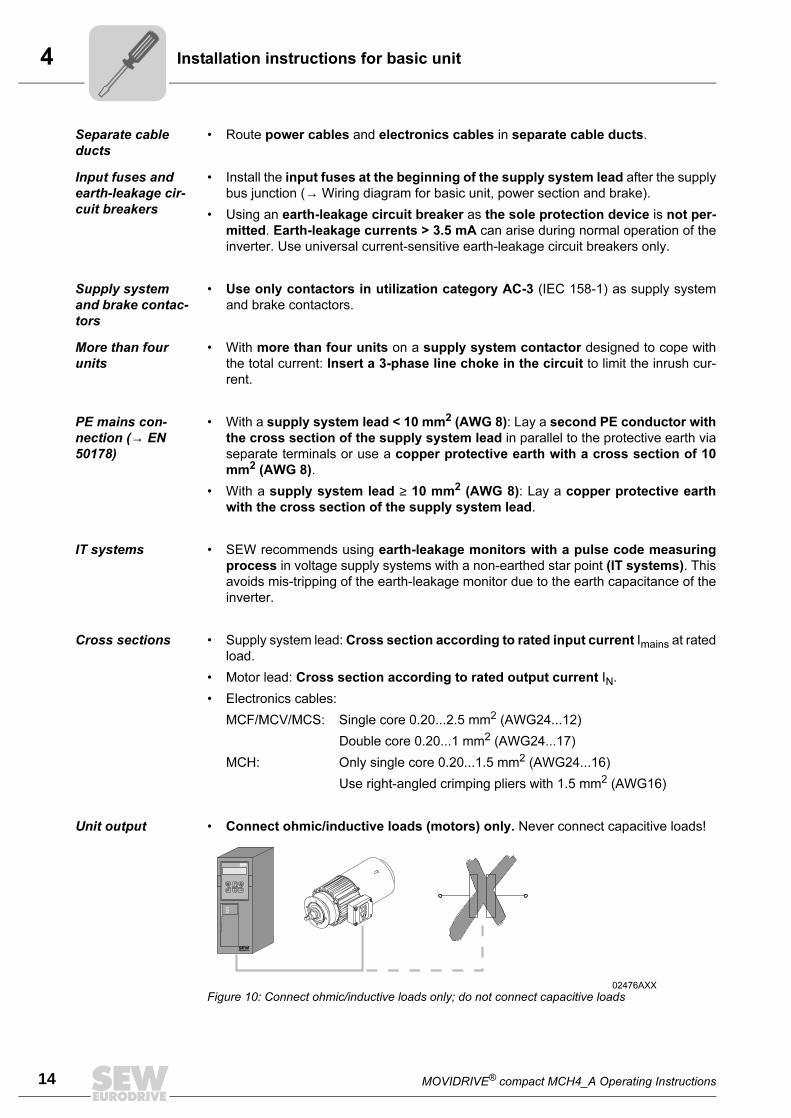
Unit output • Connect ohmic/inductive loads (motors) only. Never connect capacitive loads!
02476AXX
Figure 10: Connect ohmic/inductive loads only; do not connect capacitive loads
E QQ
MOVIDRIVE® compact MCH4_A Operating Instructions 15
4Installation instructions for basic unit
Connecting brak-
ing resistors
• Use two closely twisted cables or a 2-core shielded power cable. Cross section
according to the rated output current of the inverter.
• Protect the braking resistor with a bimetallic relay / thermal overload relay (→ Wir-
ing diagram for basic unit, power section and brake). Set the trip current according
to the technical data of the braking resistor.
Operating brak-
ing resistors
• The connection leads to the braking resistors carry a high DC voltage (approx. 900
V) during rated operation.
• The surfaces of the braking resistors get very hot when the braking resistors are
loaded with PN. Select a suitable installation position. As a rule, braking resistors
are mounted on the switch cabinet roof.
• Install the flat-type braking resistors together with the appropriate touch guard.
Binary inputs /
binary outputs
• The binary inputs are electrically isolated by optocouplers.
• The binary outputs are short-circuit proof, although they are not interference-
voltage-proof (exception: relay output DOØ1). External voltage can cause irrepara-
ble damage to the binary outputs.
Shielding and
earthing
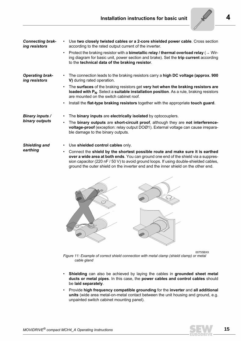
• Use shielded control cables only.
• Connect the shield by the shortest possible route and make sure it is earthed
over a wide area at both ends. You can ground one end of the shield via a suppres-
sion capacitor (220 nF / 50 V) to avoid ground loops. If using double-shielded cables,
ground the outer shield on the inverter end and the inner shield on the other end.
• Shielding can also be achieved by laying the cables in grounded sheet metal
ducts or metal pipes. In this case, the power cables and control cables should
be laid separately.
• Provide high frequency compatible grounding for the inverter and all additional
units (wide area metal-on-metal contact between the unit housing and ground, e.g.
unpainted switch cabinet mounting panel).
00755BXX
Figure 11: Example of correct shield connection with metal clamp (shield clamp) or metal
cable gland
4
16 MOVIDRIVE® compact MCH4_A Operating Instructions
Installation instructions for basic unit
Line filter • Sizes 1 and 2 are fitted with an line filter as standard. This line filter ensures that
limit value class A is maintained on the supply side. Use an NF...-... line filter as
an option to maintain the class B limit.
• The NF...-... line filter option is required for sizes 3 to 5 to maintain class A and B
limits.
• Install the line filter close to the inverter, but outside the minimum clearance re-
quired for cooling.
• Restrict the cable between the line filter and the inverter to the absolute mini-
mum length required, and never more than 400 mm (15.8 in). Unshielded, twisted
cables are sufficient. Also use unshielded cables as the supply system lead.
• This line filter must be installed either directly at the entry point into the switch
cabinet or in the immediate vicinity of the inverter if several inverters are con-
nected to the same line filter. The line filter must be chosen on the basis of the total
current of the connected inverters.
• No EMC limits are specified for interference emission in voltage supply sys-
tems without an earthed star point (IT systems). The effectiveness of line filters
in IT systems is severely limited.
Interference
emission
SEW recommends the following EMC measures on the output side to maintain the
class A and B limits:
• Shielded motor feeder
• HD... output choke option
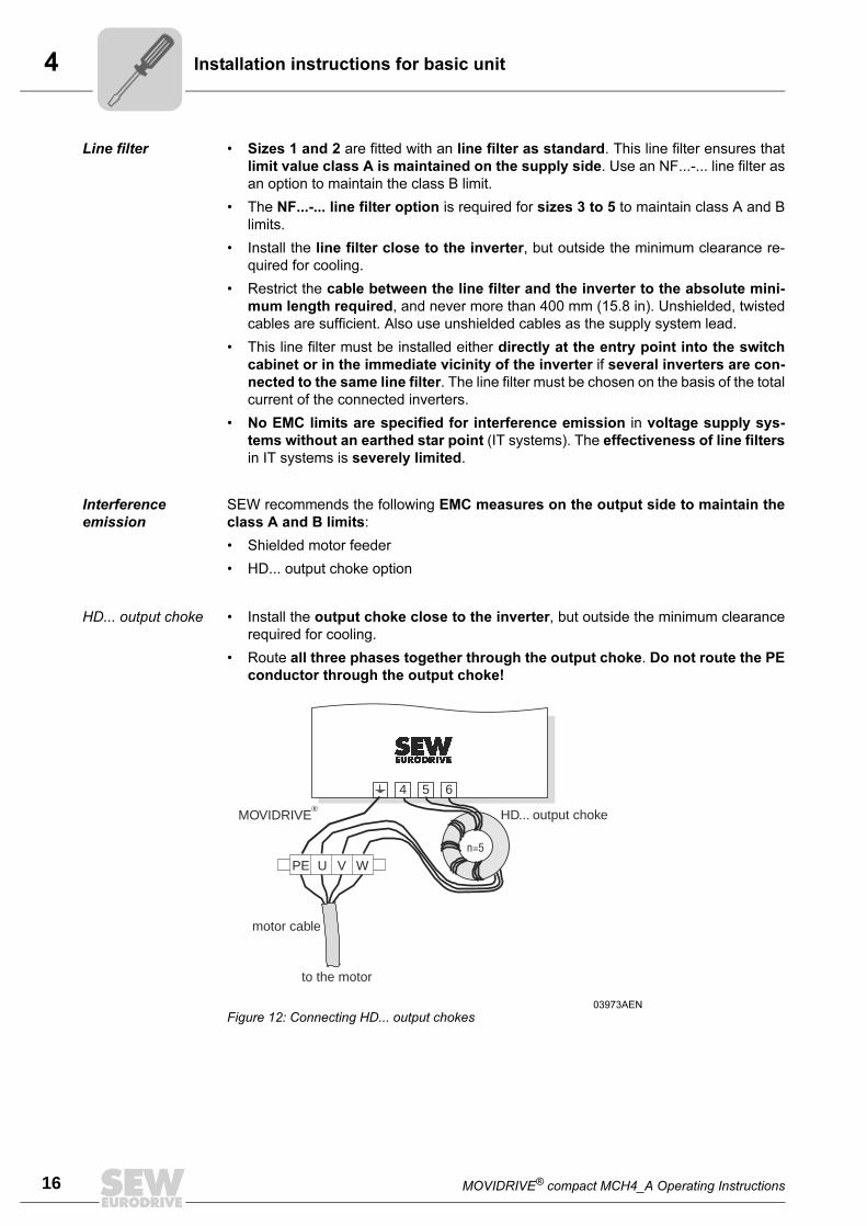
HD... output choke • Install the output choke close to the inverter, but outside the minimum clearance
required for cooling.
• Route all three phases together through the output choke. Do not route the PE
conductor through the output choke!
03973AEN
Figure 12: Connecting HD... output chokes
4 5 6
MOVIDRIVE®
U V WPEn=5
HD... output choke
to the motor
motor cable
MOVIDRIVE® compact MCH4_A Operating Instructions 17
4Installation instructions for PROFIBUS-DP interface (MCH41A)
4.2 Installation instructions for PROFIBUS-DP interface (MCH41A)
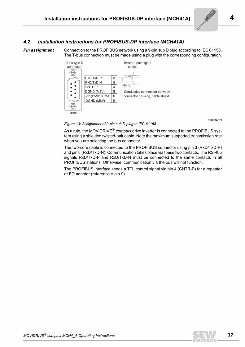
Pin assignment Connection to the PROFIBUS network using a 9-pin sub D plug according to IEC 61158.
The T-bus connection must be made using a plug with the corresponding configuration.
As a rule, the MOVIDRIVE® compact drive inverter is connected to the PROFIBUS sys-
tem using a shielded twisted-pair cable. Note the maximum supported transmission rate
when you are selecting the bus connector.
The two-core cable is connected to the PROFIBUS connector using pin 3 (RxD/TxD-P)
and pin 8 (RxD/TxD-N). Communication takes place via these two contacts. The RS-485
signals RxD/TxD-P and RxD/TxD-N must be connected to the same contacts in all
PROFIBUS stations. Otherwise, communication via the bus will not function.
The PROFIBUS interface sends a TTL control signal via pin 4 (CNTR-P) for a repeater
or FO adapter (reference = pin 9).
02893AEN
Figure 13: Assignment of 9-pin sub D plug to IEC 61158
4
18 MOVIDRIVE® compact MCH4_A Operating Instructions
Installation instructions for PROFIBUS-DP interface (MCH41A)
Shielding and
routing bus
cables
The PROFIBUS interface supports RS-485 transmission technology and requires the
cable type A to IEC 61158 specified as the physical medium for PROFIBUS. This cable
must be a shielded, twisted-pair two-core cable.
Having the bus cable correctly shielded cuts out parasitic interference which can occur
in an industrial environment. The following measures enable the best possible shielding
to be achieved:
• Tighten the retaining screws of plugs, modules and equipotential bonding conductors
until finger-tight.
• Only use connectors with a metal housing or a metallized housing.
• Connect the shield in the connector over a large surface area.
• Apply the bus cable shielding on both ends.
• Do not route the signal and bus cables in parallel to the power cables (motor feed-
ers); use separate cable ducts if at all possible.
• Only use metal, grounded cable racks in industrial environments.
• Join the signal cables and the associated equipotential bonding together at closely
spaced intervals by the shortest route.
• Avoid using plug connections to extend bus cables.
• Route the bus cables closely adjacent to available grounding surfaces.
Bus termination
with MCH41A
MCH41A is not provided with bus terminating resistors so that the bus system can be
taken into operation more easily and in order to reduce the number of error sources.
Use a plug with an integrated bus terminating resistor if the inverter is at the start or finish
of a PROFIBUS segment and only one PROFIBUS cable is leading to the inverter.
Switch on the bus terminating resistors on this PROFIBUS plug.
In the event of fluctuations in the ground potential, a compensating current may flow
along the shield which is connected at both ends and to the ground potential (PE). In this
case, make adequate provision for equipotential bonding in accordance with the rele-
vant VDE regulations.
MOVIDRIVE® compact MCH4_A Operating Instructions 19
4Installation instructions for PROFIBUS-DP interface (MCH41A)
Setting the sta-
tion address with
MCH41A
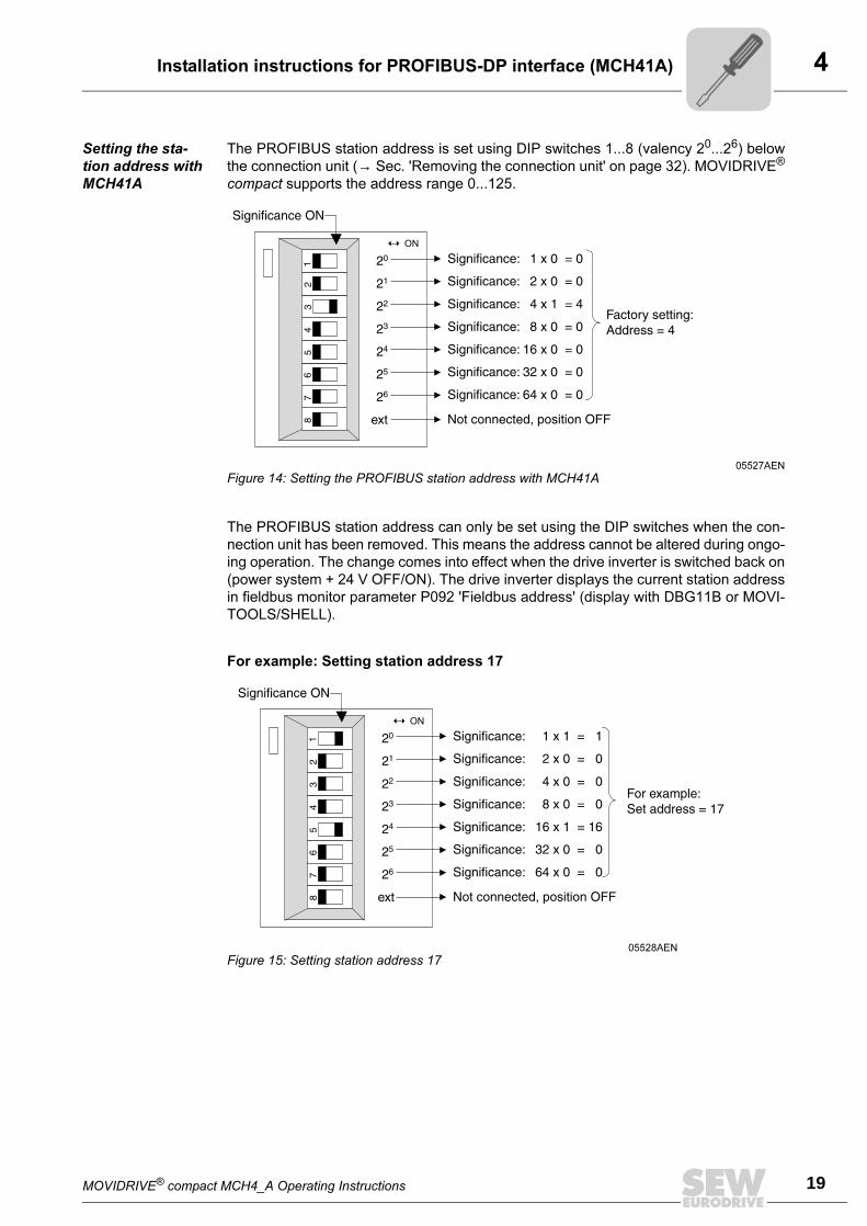
The PROFIBUS station address is set using DIP switches 1...8 (valency 20...26) below
the connection unit (→ Sec. 'Removing the connection unit' on page 32). MOVIDRIVE®
compact supports the address range 0...125.
The PROFIBUS station address can only be set using the DIP switches when the con-
nection unit has been removed. This means the address cannot be altered during ongo-
ing operation. The change comes into effect when the drive inverter is switched back on
(power system + 24 V OFF/ON). The drive inverter displays the current station address
in fieldbus monitor parameter P092 'Fieldbus address' (display with DBG11B or MOVI-
TOOLS/SHELL).
For example: Setting station address 17
05527AEN
Figure 14: Setting the PROFIBUS station address with MCH41A
05528AEN
Figure 15: Setting station address 17
4
20 MOVIDRIVE® compact MCH4_A Operating Instructions
Installation instructions for INTERBUS FO interface (MCH42A)
4.3 Installation instructions for INTERBUS FO interface (MCH42A)
Bus connection
via fiber optic
cable (FO)
The bus connection uses fiber optic cables. You can use either polymer fiber cables or
HCS cables.
Polymer fiber
cables
This type of cable is used for distances of up to 70 meters between two INTERBUS sta-
tions. Various types are available depending on the application. This cable type offers
straightforward and inexpensive installation.
HCS cables This type of cable can be used over distances of up to 500 m, since it has much lower
light attenuation values than polymer fiber cable.
The bus cable must be at least 1 meter long. Cable bridges from Phoenix Contact must
be used for shorter distances.
Checklist for installing FO cables
Routing FO cables • Do not exceed the maximum cable length
• Note the permitted bending radii
• Do not crush or kink FO cables
• Do not exceed the strain limit when routing
• When unreeling FO cables for installation, always use an unreeling fixture
Protective mea-
sures for FO
cables
• Protect them from strain and impermissibly small bending radii
• Route them without loops
• Protect them against sharp edges
• Use a special cable type when routing in special areas (e.g. laying underground or
in proximity to welding robots)
Pre-fabricating FO
cables
• Strip the insulation off the outer sheath and the individual cores without damaging
them
• Fix the individual core in the plug (strain relief)
• Polish and install the end of the plug in accordance with the guidelines
Calibrating FO
cables
• Check the light intensity complies with the limit values (optical diagnosis with CMD
tool or FO measuring instrument)
Connecting FO
plugs
The fiber optic cable is connected to MOVIDRIVE® compact MCH42A using plugs called
F-SMA plugs. You need a pair of plugs for the incoming and outgoing remote bus (trans-
mitter and receiver). SEW recommends using F-SMA plugs with an anti-kinking sleeve
to ensure that the optimum bending radius is maintained.
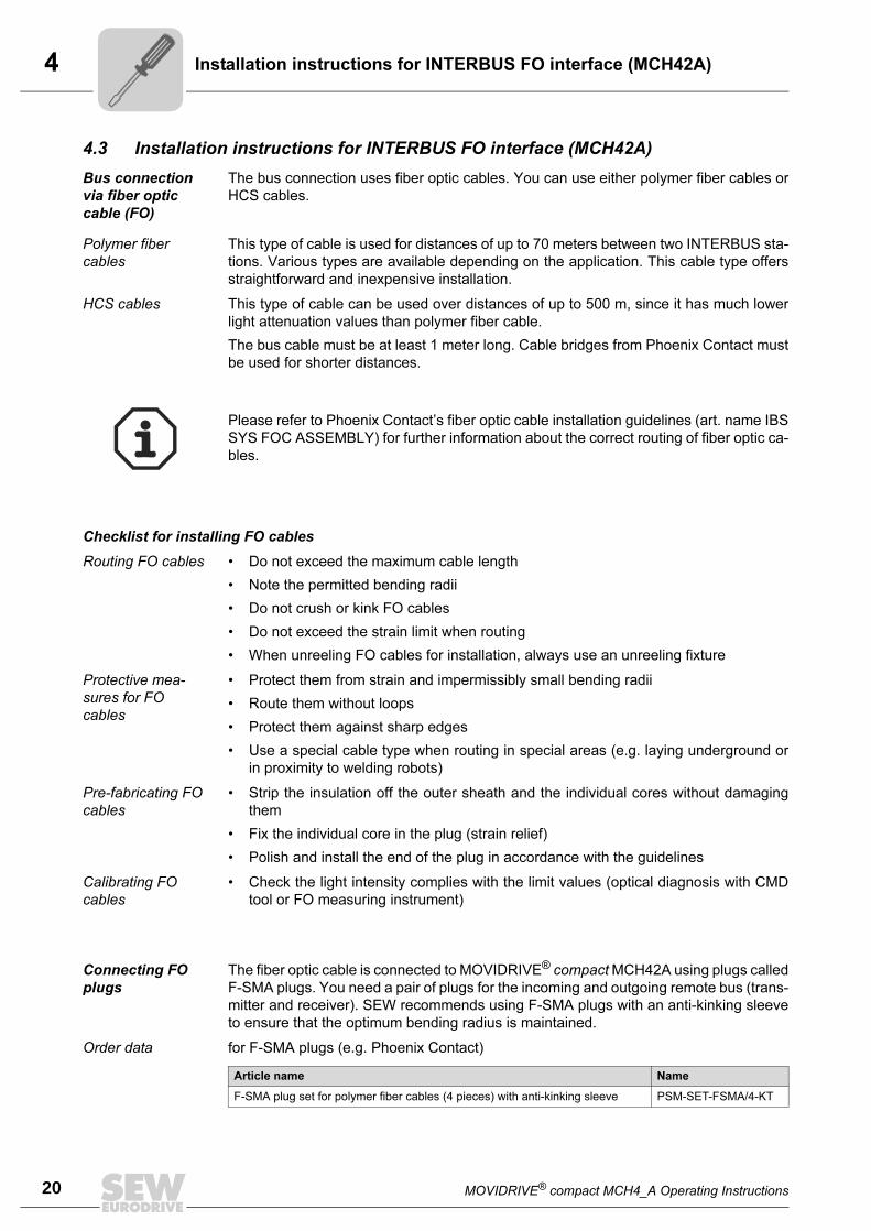
Order data for F-SMA plugs (e.g. Phoenix Contact)
Please refer to Phoenix Contact’s fiber optic cable installation guidelines (art. name IBS
SYS FOC ASSEMBLY) for further information about the correct routing of fiber optic ca-
bles.
Article name Name
F-SMA plug set for polymer fiber cables (4 pieces) with anti-kinking sleeve PSM-SET-FSMA/4-KT
MOVIDRIVE® compact MCH4_A Operating Instructions 21
4Installation instructions for INTERBUS FO interface (MCH42A)
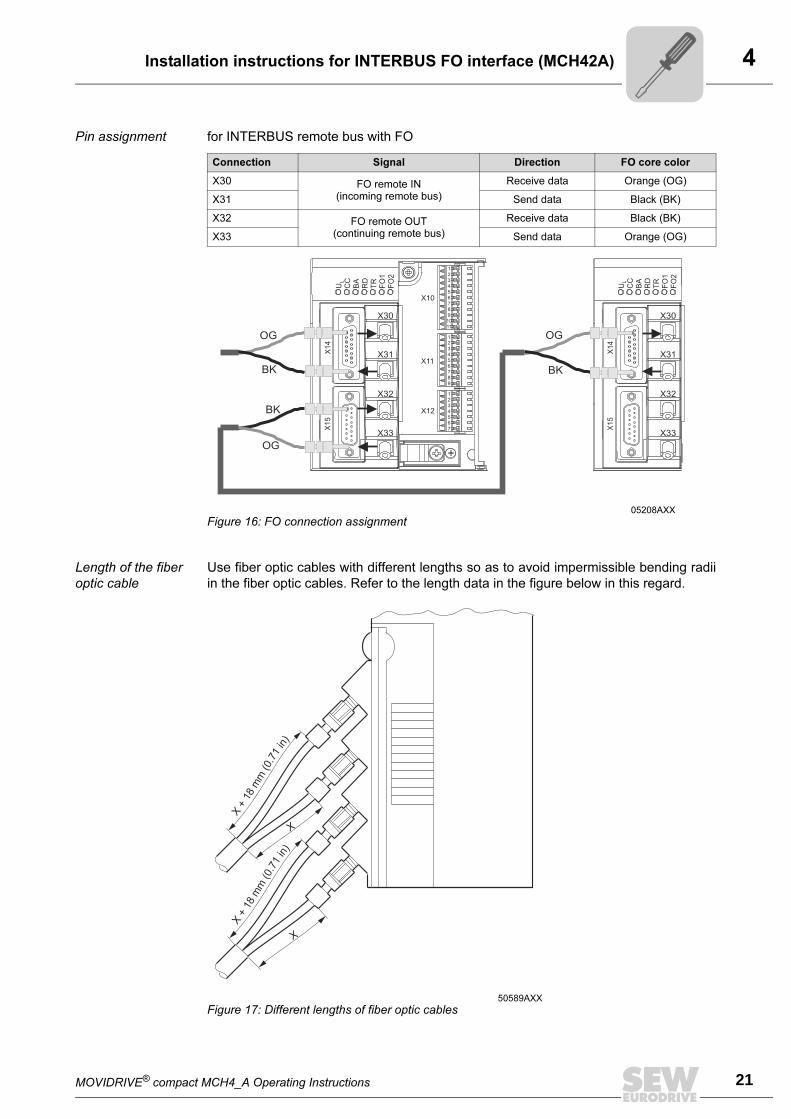
Pin assignment for INTERBUS remote bus with FO
Length of the fiber
optic cable
Use fiber optic cables with different lengths so as to avoid impermissible bending radii
in the fiber optic cables. Refer to the length data in the figure below in this regard.
Connection Signal Direction FO core color
X30 FO remote IN(incoming remote bus)
Receive data Orange (OG)
X31 Send data Black (BK)
X32 FO remote OUT(continuing remote bus)
Receive data Black (BK)
X33 Send data Orange (OG)
05208AXX
Figure 16: FO connection assignment
X1
4X
15
X10
X11
X12
X30
X31
X32
X33
1
2
3
4
5
6
7
8
9
10
11
1
2
3
4
5
6
7
8
9
1
2
3
4
5
6
7
U CC
BA
RD
TR
FO
1
FO
2
L
X1
4X
15
X30
X31
X32
X33
U CC
BA
RD
TR
FO
1
FO
2
L
OG
OG
OG
BK
BK
BK
50589AXX
Figure 17: Different lengths of fiber optic cables
X+18mm(0.71in)
X+18mm(0.71in)
X
X
4
22 MOVIDRIVE® compact MCH4_A Operating Instructions
Installation instructions for INTERBUS FO interface (MCH42A)
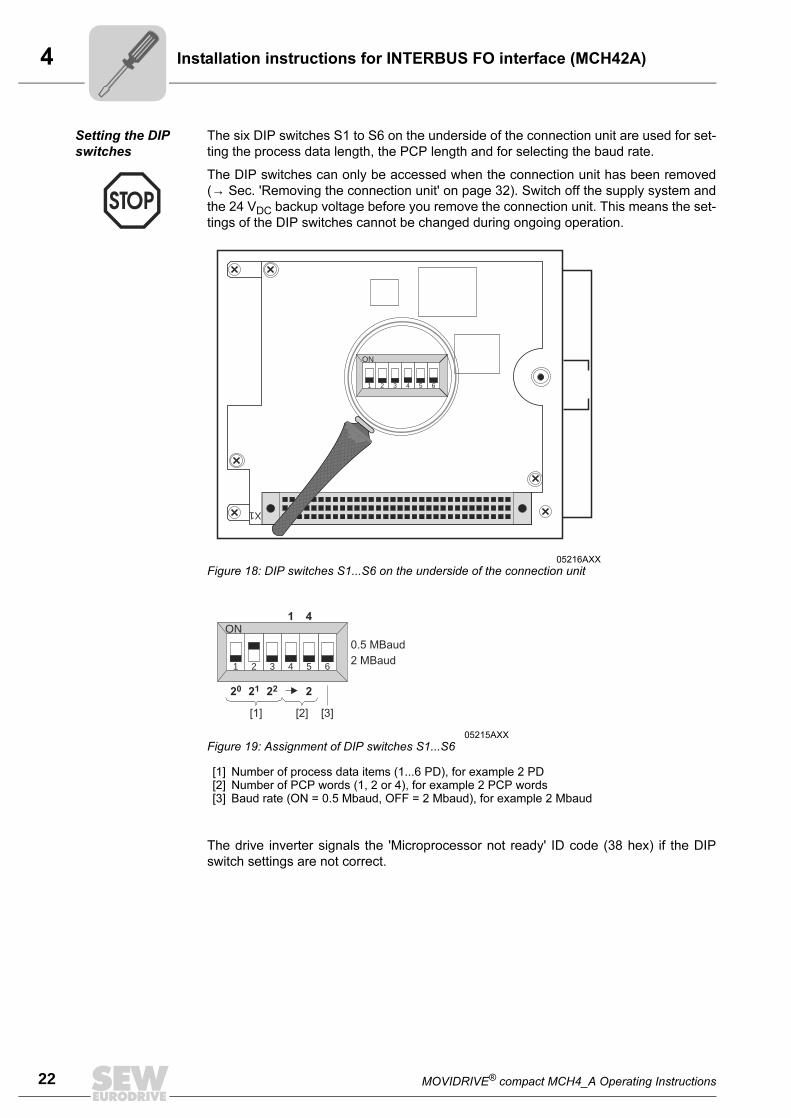
Setting the DIP
switches
The six DIP switches S1 to S6 on the underside of the connection unit are used for set-
ting the process data length, the PCP length and for selecting the baud rate.
The drive inverter signals the 'Microprocessor not ready' ID code (38 hex) if the DIP
switch settings are not correct.
The DIP switches can only be accessed when the connection unit has been removed
(→ Sec. 'Removing the connection unit' on page 32). Switch off the supply system and
the 24 VDC backup voltage before you remove the connection unit. This means the set-
tings of the DIP switches cannot be changed during ongoing operation.
05216AXX
Figure 18: DIP switches S1...S6 on the underside of the connection unit
05215AXX
Figure 19: Assignment of DIP switches S1...S6
[1] Number of process data items (1...6 PD), for example 2 PD[2] Number of PCP words (1, 2 or 4), for example 2 PCP words[3] Baud rate (ON = 0.5 Mbaud, OFF = 2 Mbaud), for example 2 Mbaud
X1
1 2 3 4 5 6
ON
1 2 3 4 5 6
ON
1 2 3 4 5 6
ON
[1] [2] [3]
0.5 MBaud
2 MBaud
20 2221 2
1 4
MOVIDRIVE® compact MCH4_A Operating Instructions 23
4Installation instructions for INTERBUS FO interface (MCH42A)
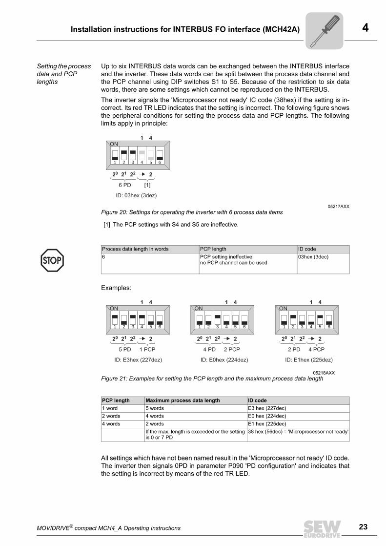
Setting the process
data and PCP
lengths
Up to six INTERBUS data words can be exchanged between the INTERBUS interface
and the inverter. These data words can be split between the process data channel and
the PCP channel using DIP switches S1 to S5. Because of the restriction to six data
words, there are some settings which cannot be reproduced on the INTERBUS.
The inverter signals the 'Microprocessor not ready' IC code (38hex) if the setting is in-
correct. Its red TR LED indicates that the setting is incorrect. The following figure shows
the peripheral conditions for setting the process data and PCP lengths. The following
limits apply in principle:
Examples:
All settings which have not been named result in the 'Microprocessor not ready' ID code.
The inverter then signals 0PD in parameter P090 'PD configuration' and indicates that
the setting is incorrect by means of the red TR LED.
05217AXX
Figure 20: Settings for operating the inverter with 6 process data items
[1] The PCP settings with S4 and S5 are ineffective.
1 2 3 4 5 6
ON
6 PD [1]
20 2221 2
1 4
ID: 03hex (3dez)
Process data length in words PCP length ID code
6 PCP setting ineffective;no PCP channel can be used
03hex (3dec)
05218AXX
Figure 21: Examples for setting the PCP length and the maximum process data length
PCP length Maximum process data length ID code
1 word 5 words E3 hex (227dec)
2 words 4 words E0 hex (224dec)
4 words 2 words E1 hex (225dec)
If the max. length is exceeded or the setting is 0 or 7 PD
38 hex (56dec) = 'Microprocessor not ready'
1 2 3 4 5 6 1 2 3 4 5 6 1 2 3 4 5 6
ON ON ON
5 PD 4 PD 2 PD1 PCP 2 PCP 4 PCP
20 20 2022 22 2221 21 212 2 2
1 1 14 4 4
ID: E3hex (227dez) ID: E0hex (224dez) ID: E1hex (225dez)
4
24 MOVIDRIVE® compact MCH4_A Operating Instructions
UL compliant installation
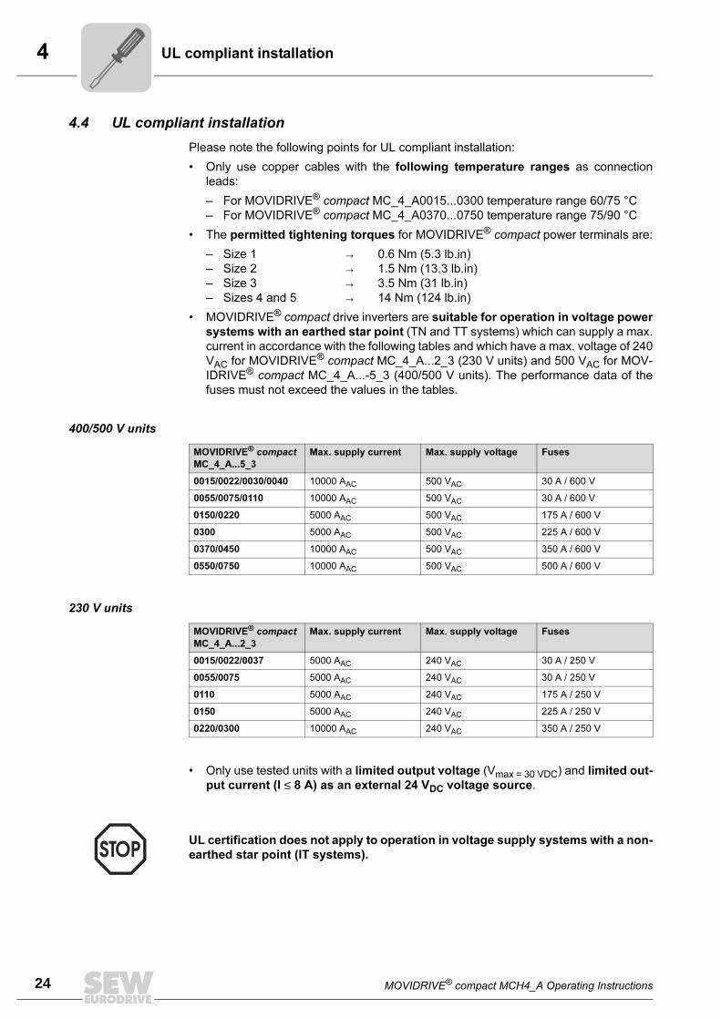
4.4 UL compliant installation
Please note the following points for UL compliant installation:
• Only use copper cables with the following temperature ranges as connection
leads:
– For MOVIDRIVE® compact MC_4_A0015...0300 temperature range 60/75 °C
– For MOVIDRIVE® compact MC_4_A0370...0750 temperature range 75/90 °C
• The permitted tightening torques for MOVIDRIVE® compact power terminals are:
– Size 1 → 0.6 Nm (5.3 lb.in)
– Size 2 → 1.5 Nm (13.3 lb.in)
– Size 3 → 3.5 Nm (31 lb.in)
– Sizes 4 and 5 → 14 Nm (124 lb.in)
• MOVIDRIVE® compact drive inverters are suitable for operation in voltage power
systems with an earthed star point (TN and TT systems) which can supply a max.
current in accordance with the following tables and which have a max. voltage of 240
VAC for MOVIDRIVE® compact MC_4_A...2_3 (230 V units) and 500 VAC for MOV-
IDRIVE® compact MC_4_A...-5_3 (400/500 V units). The performance data of the
fuses must not exceed the values in the tables.
400/500 V units
230 V units
• Only use tested units with a limited output voltage (Vmax = 30 VDC) and limited out-
put current (I ≤ 8 A) as an external 24 VDC voltage source.
MOVIDRIVE® compact
MC_4_A...5_3
Max. supply current Max. supply voltage Fuses
0015/0022/0030/0040 10000 AAC 500 VAC 30 A / 600 V
0055/0075/0110 10000 AAC 500 VAC 30 A / 600 V
0150/0220 5000 AAC 500 VAC 175 A / 600 V
0300 5000 AAC 500 VAC 225 A / 600 V
0370/0450 10000 AAC 500 VAC 350 A / 600 V
0550/0750 10000 AAC 500 VAC 500 A / 600 V
MOVIDRIVE® compact
MC_4_A...2_3
Max. supply current Max. supply voltage Fuses
0015/0022/0037 5000 AAC 240 VAC 30 A / 250 V
0055/0075 5000 AAC 240 VAC 30 A / 250 V
0110 5000 AAC 240 VAC 175 A / 250 V
0150 5000 AAC 240 VAC 225 A / 250 V
0220/0300 10000 AAC 240 VAC 350 A / 250 V
UL certification does not apply to operation in voltage supply systems with a non-
earthed star point (IT systems).
MOVIDRIVE® compact MCH4_A Operating Instructions 25
4Power shield clamp
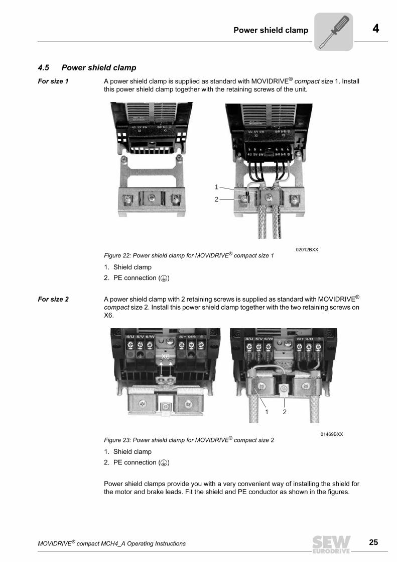
4.5 Power shield clamp
For size 1 A power shield clamp is supplied as standard with MOVIDRIVE® compact size 1. Install
this power shield clamp together with the retaining screws of the unit.
1. Shield clamp
2. PE connection ()
For size 2 A power shield clamp with 2 retaining screws is supplied as standard with MOVIDRIVE®
compact size 2. Install this power shield clamp together with the two retaining screws on
X6.
1. Shield clamp
2. PE connection ()
Power shield clamps provide you with a very convenient way of installing the shield for
the motor and brake leads. Fit the shield and PE conductor as shown in the figures.
02012BXX
Figure 22: Power shield clamp for MOVIDRIVE® compact size 1
1
2
01469BXX
Figure 23: Power shield clamp for MOVIDRIVE® compact size 2
4
26 MOVIDRIVE® compact MCH4_A Operating Instructions
Touch guard
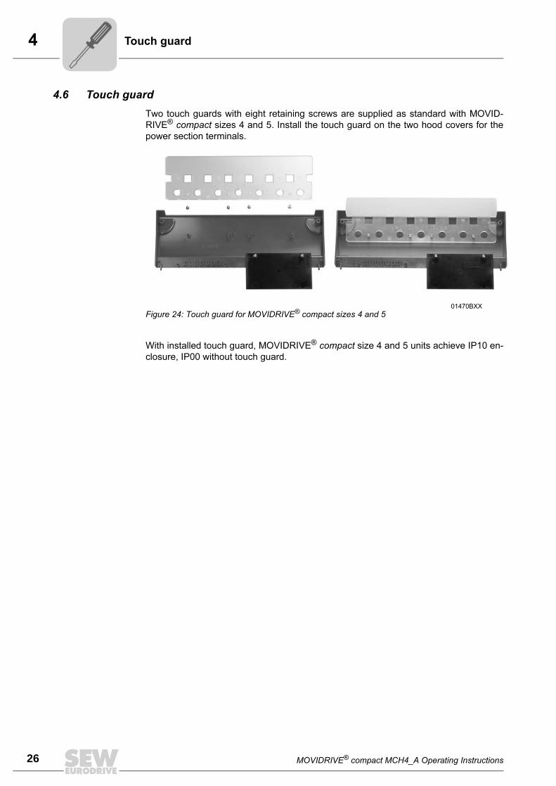
4.6 Touch guard
Two touch guards with eight retaining screws are supplied as standard with MOVID-
RIVE® compact sizes 4 and 5. Install the touch guard on the two hood covers for the
power section terminals.
With installed touch guard, MOVIDRIVE® compact size 4 and 5 units achieve IP10 en-
closure, IP00 without touch guard.
01470BXX
Figure 24: Touch guard for MOVIDRIVE® compact sizes 4 and 5
MOVIDRIVE® compact MCH4_A Operating Instructions 27
4Wiring diagram, basic unit
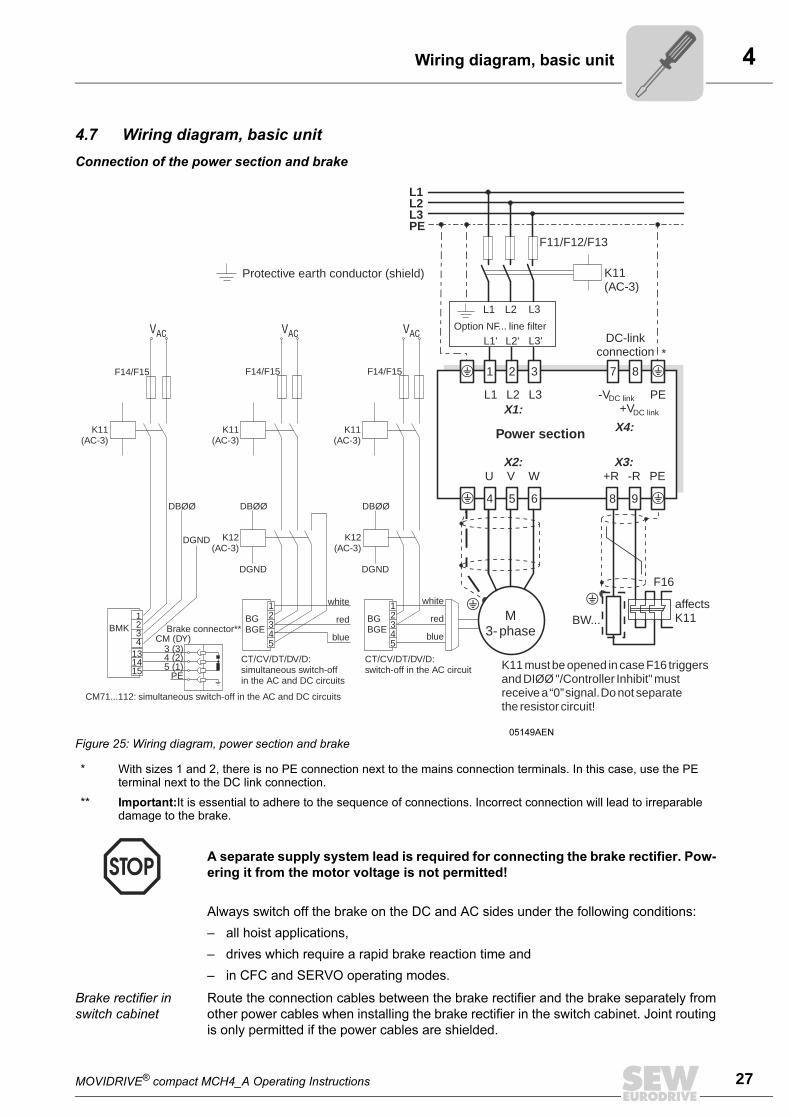
4.7 Wiring diagram, basic unit
Connection of the power section and brake
Always switch off the brake on the DC and AC sides under the following conditions:
– all hoist applications,
– drives which require a rapid brake reaction time and
– in CFC and SERVO operating modes.
Brake rectifier in
switch cabinet
Route the connection cables between the brake rectifier and the brake separately from
other power cables when installing the brake rectifier in the switch cabinet. Joint routing
is only permitted if the power cables are shielded.
05149AEN
Figure 25: Wiring diagram, power section and brake
* With sizes 1 and 2, there is no PE connection next to the mains connection terminals. In this case, use the PE terminal next to the DC link connection.
** Important:It is essential to adhere to the sequence of connections. Incorrect connection will lead to irreparable damage to the brake.
A separate supply system lead is required for connecting the brake rectifier. Pow-
ering it from the motor voltage is not permitted!
BW...
X1:
X2: X3:
F14/F15F14/F15
L1 L2 L3
L1' L2' L3'
F11/F12/F13
K11(AC-3)
L1L2L3PE
L1 L2 L3
U V W +R -R PE
1 2 3 7 8
4 5 6 8 9
12345
12345
K12(AC-3)
K12(AC-3)
DBØØDBØØDBØØ
DGNDDGND
DGND
BGBGE
BGBGE
F16
*
F14/F15
K11(AC-3)
K11(AC-3)
K11(AC-3)
1234
131415
BMK
3 (3)CM (DY)
4 (2)5 (1)
PE
DC link
DC link
CM71...112: simultaneous switch-off in the AC and DC circuits
VAC VAC VAC
Brake connector**M
3-phase
affectsK11
DC-linkconnection
Option NF... line filter
CT/CV/DT/DV/D:switch-off in the AC circuit
CT/CV/DT/DV/D:simultaneous switch-offin the AC and DC circuits
white
red
blue
white
red
blue
-V PE+V
Power section X4:
Protective earth conductor (shield)
K11mustbeopened incaseF16 triggersandreceivea“0”signal.Donot separatethe resistor circuit!
DIØØ"/Controller Inhibit"must
4
28 MOVIDRIVE® compact MCH4_A Operating Instructions
Wiring diagram, basic unit
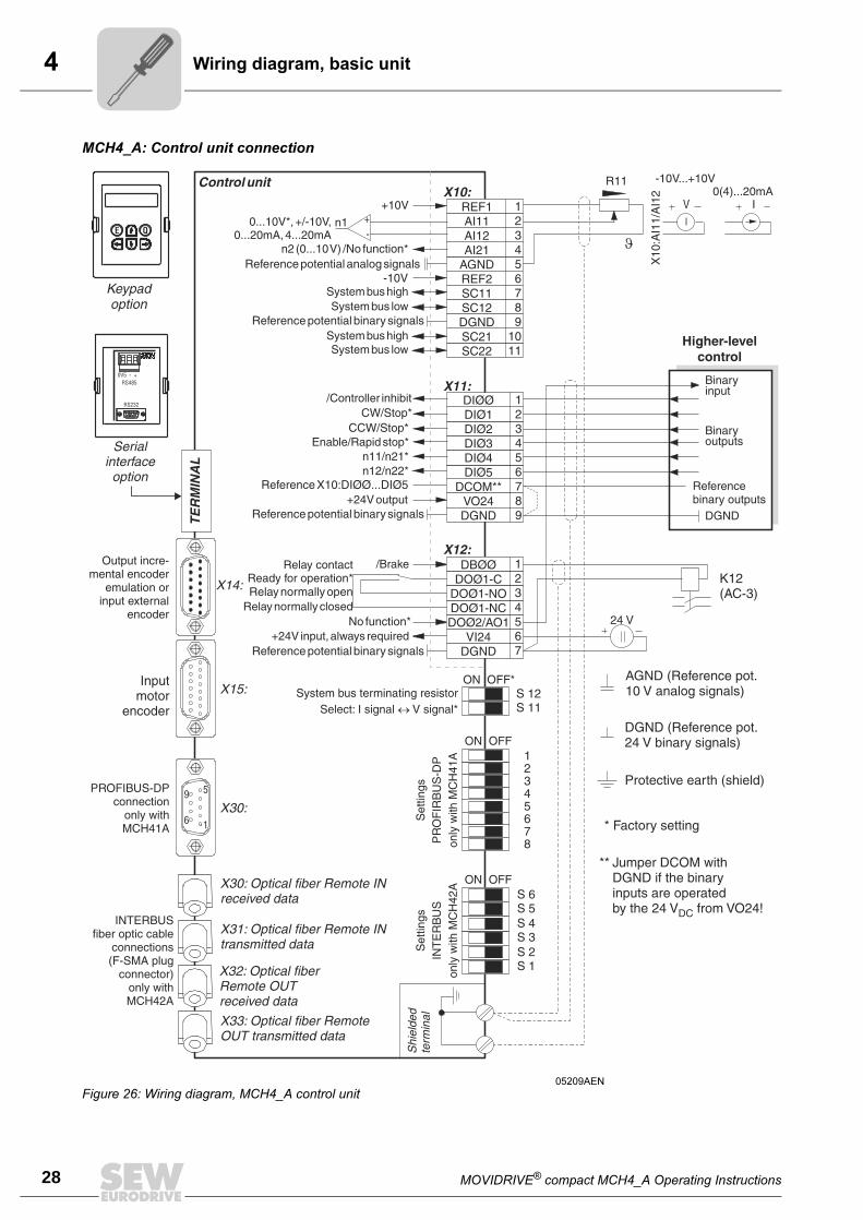
MCH4_A: Control unit connection
05209AEN
Figure 26: Wiring diagram, MCH4_A control unit
MOVIDRIVE® compact MCH4_A Operating Instructions 29
4Wiring diagram, basic unit
Analog output
AO1
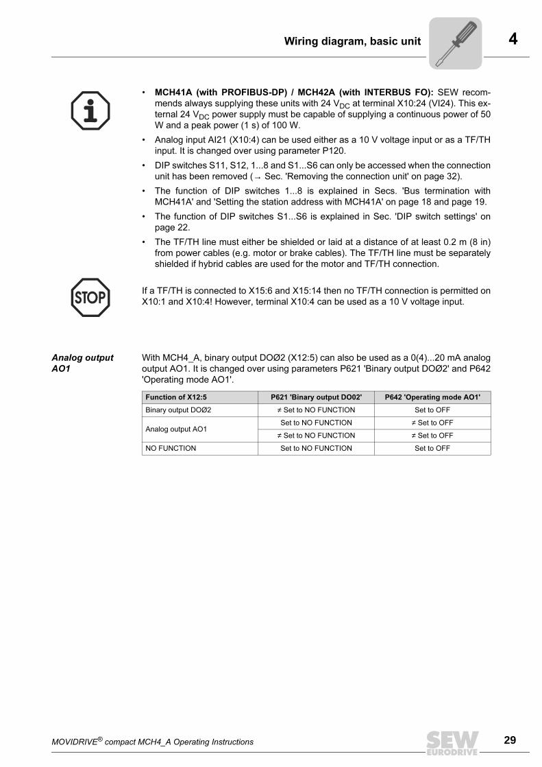
With MCH4_A, binary output DOØ2 (X12:5) can also be used as a 0(4)...20 mA analog
output AO1. It is changed over using parameters P621 'Binary output DOØ2' and P642
'Operating mode AO1'.
• MCH41A (with PROFIBUS-DP) / MCH42A (with INTERBUS FO): SEW recom-
mends always supplying these units with 24 VDC at terminal X10:24 (VI24). This ex-
ternal 24 VDC power supply must be capable of supplying a continuous power of 50
W and a peak power (1 s) of 100 W.
• Analog input AI21 (X10:4) can be used either as a 10 V voltage input or as a TF/TH
input. It is changed over using parameter P120.
• DIP switches S11, S12, 1...8 and S1...S6 can only be accessed when the connection
unit has been removed (→ Sec. 'Removing the connection unit' on page 32).
• The function of DIP switches 1...8 is explained in Secs. 'Bus termination with
MCH41A' and 'Setting the station address with MCH41A' on page 18 and page 19.
• The function of DIP switches S1...S6 is explained in Sec. 'DIP switch settings' on
page 22.
• The TF/TH line must either be shielded or laid at a distance of at least 0.2 m (8 in)
from power cables (e.g. motor or brake cables). The TF/TH line must be separately
shielded if hybrid cables are used for the motor and TF/TH connection.
If a TF/TH is connected to X15:6 and X15:14 then no TF/TH connection is permitted on
X10:1 and X10:4! However, terminal X10:4 can be used as a 10 V voltage input.
Function of X12:5 P621 'Binary output DO02' P642 'Operating mode AO1'
Binary output DOØ2 ≠ Set to NO FUNCTION Set to OFF
Analog output AO1Set to NO FUNCTION ≠ Set to OFF
≠ Set to NO FUNCTION ≠ Set to OFF
NO FUNCTION Set to NO FUNCTION Set to OFF
4
30 MOVIDRIVE® compact MCH4_A Operating Instructions
Wiring diagram, basic unit
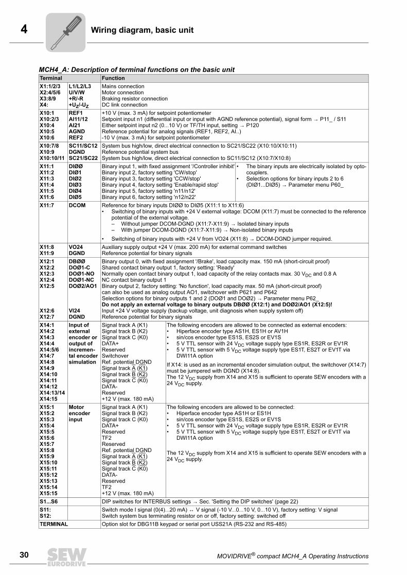
MCH4_A: Description of terminal functions on the basic unitTerminal Function
X1:1/2/3X2:4/5/6X3:8/9X4:
L1/L2/L3U/V/W+R/-R+UZ/-UZ
Mains connectionMotor connectionBraking resistor connectionDC link connection
X10:1X10:2/3X10:4X10:5X10:6
REF1AI11/12AI21AGNDREF2
+10 V (max. 3 mA) for setpoint potentiometerSetpoint input n1 (differential input or input with AGND reference potential), signal form → P11_ / S11Either setpoint input n2 (0...10 V) or TF/TH input, setting → P120Reference potential for analog signals (REF1, REF2, AI..)-10 V (max. 3 mA) for setpoint potentiometer
X10:7/8X10:9X10:10/11
SC11/SC12DGNDSC21/SC22
System bus high/low, direct electrical connection to SC21/SC22 (X10:10/X10:11)Reference potential system busSystem bus high/low, direct electrical connection to SC11/SC12 (X10:7/X10:8)
X11:1X11:2X11:3X11:4X11:5X11:6
DIØØDIØ1DIØ2DIØ3DIØ4DIØ5
Binary input 1, with fixed assignment '/Controller inhibit'Binary input 2, factory setting 'CW/stop'Binary input 3, factory setting 'CCW/stop'Binary input 4, factory setting 'Enable/rapid stop'Binary input 5, factory setting 'n11/n12'Binary input 6, factory setting 'n12/n22'
• The binary inputs are electrically isolated by opto-couplers.
• Selection options for binary inputs 2 to 6 (DIØ1...DIØ5) → Parameter menu P60_
X11:7 DCOM Reference for binary inputs DIØØ to DIØ5 (X11:1 to X11:6)• Switching of binary inputs with +24 V external voltage: DCOM (X11:7) must be connected to the reference
potential of the external voltage.– Without jumper DCOM-DGND (X11:7-X11:9) → Isolated binary inputs– With jumper DCOM-DGND (X11:7-X11:9) → Non-isolated binary inputs
• Switching of binary inputs with +24 V from VO24 (X11:8) → DCOM-DGND jumper required.
X11:8X11:9
VO24DGND
Auxiliary supply output +24 V (max. 200 mA) for external command switchesReference potential for binary signals
X12:1X12:2X12:3X12:4X12:5
X12:6X12:7
DBØØDOØ1-CDOØ1-NODOØ1-NCDOØ2/AO1
VI24DGND
Binary output 0, with fixed assignment '/Brake', load capacity max. 150 mA (short-circuit proof)Shared contact binary output 1, factory setting: 'Ready'Normally open contact binary output 1, load capacity of the relay contacts max. 30 VDC and 0.8 ANC contact binary output 1Binary output 2, factory setting: 'No function', load capacity max. 50 mA (short-circuit proof)can also be used as analog output AO1, switchover with P621 and P642Selection options for binary outputs 1 and 2 (DOØ1 and DOØ2) → Parameter menu P62_Do not apply an external voltage to binary outputs DBØØ (X12:1) and DOØ2/AO1 (X12:5)!Input +24 V voltage supply (backup voltage, unit diagnosis when supply system off)Reference potential for binary signals
X14:1X14:2X14:3X14:4X14:5/6X14:7X14:8X14:9X14:10X14:11X14:12X14:13/14X14:15
Input of external encoder or output of incremen-tal encoder simulation
Signal track A (K1)Signal track B (K2)Signal track C (K0)DATA+ReservedSwitchoverRef. potential DGNDSignal track A (K1)Signal track B (K2)Signal track C (K0)DATA-Reserved+12 V (max. 180 mA)
The following encoders are allowed to be connected as external encoders:• Hiperface encoder type AS1H, ES1H or AV1H• sin/cos encoder type ES1S, ES2S or EV1S• 5 V TTL sensor with 24 VDC voltage supply type ES1R, ES2R or EV1R• 5 V TTL sensor with 5 VDC voltage supply type ES1T, ES2T or EV1T via
DWI11A option
If X14: is used as an incremental encoder simulation output, the switchover (X14:7) must be jumpered with DGND (X14:8).The 12 VDC supply from X14 and X15 is sufficient to operate SEW encoders with a 24 VDC supply.
X15:1X15:2X15:3X15:4X15:5X15:6X15:7X15:8X15:9X15:10X15:11X15:12X15:13X15:14X15:15
Motor encoder input
Signal track A (K1)Signal track B (K2)Signal track C (K0)DATA+ReservedTF2ReservedRef. potential DGNDSignal track A (K1)Signal track B (K2)Signal track C (K0)DATA-ReservedTF2+12 V (max. 180 mA)
The following encoders are allowed to be connected:• Hiperface encoder type AS1H or ES1H• sin/cos encoder type ES1S, ES2S or EV1S• 5 V TTL sensor with 24 VDC voltage supply type ES1R, ES2R or EV1R• 5 V TTL sensor with 5 VDC voltage supply type ES1T, ES2T or EV1T via
DWI11A option
The 12 VDC supply from X14 and X15 is sufficient to operate SEW encoders with a 24 VDC supply.
S1...S6 DIP switches for INTERBUS settings → Sec. 'Setting the DIP switches' (page 22)
S11:S12:
Switch mode I signal (0(4)...20 mA) ↔ V signal (-10 V...0...10 V, 0...10 V), factory setting: V signalSwitch system bus terminating resistor on or off, factory setting: switched off
TERMINAL Option slot for DBG11B keypad or serial port USS21A (RS-232 and RS-485)
MOVIDRIVE® compact MCH4_A Operating Instructions 31
4Wiring diagram, basic unit
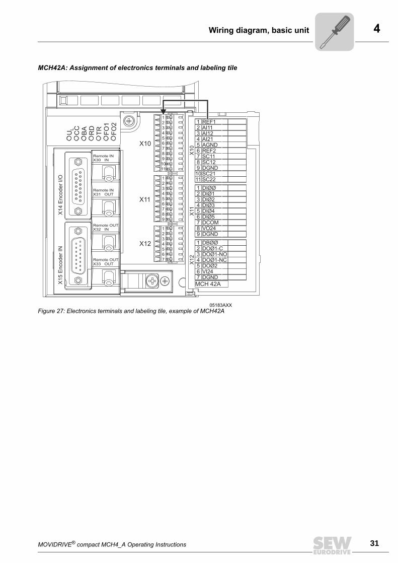
MCH42A: Assignment of electronics terminals and labeling tile
05183AXX
Figure 27: Electronics terminals and labeling tile, example of MCH42A
4
32 MOVIDRIVE® compact MCH4_A Operating Instructions
Removing the terminal unit
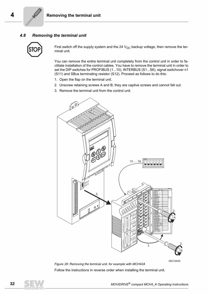
4.8 Removing the terminal unit
You can remove the entire terminal unit completely from the control unit in order to fa-
cilitate installation of the control cables. You have to remove the terminal unit in order to
set the DIP switches for PROFIBUS (1...10), INTERBUS (S1...S6), signal switchover n1
(S11) and SBus terminating resistor (S12). Proceed as follows to do this:
1. Open the flap on the terminal unit.
2. Unscrew retaining screws A and B; they are captive screws and cannot fall out.
3. Remove the terminal unit from the control unit.
Follow the instructions in reverse order when installing the terminal unit.
First switch off the supply system and the 24 VDC backup voltage, then remove the ter-
minal unit.
05213AXX
Figure 28: Removing the terminal unit, for example with MCH42A
123456789
1011
123456789
1234567
REF1AI11AI12AI21AGNDREF2SC11SC12DGNDSC21SC22
DIØØDIØ1DIØ2DIØ3DIØ4DIØ5DCOMVO24DGND
DBØØDOØ1-CDOØ1-NODOØ1-NCDOØ2VI24DGND
X10
X11
X12
MCH 42A
A
B
1.
3.
2.
2.
S12
S11ON OFF
UC
C BA R
D TR
FO1
FO2
LX
14
Enco
der
I/O
X15
Enco
der
IN
Rem
oteIN
X30IN
Remote
IN
X31O
UT
Rem
oteO
UT
X32IN
Remote
OUT
X33O
UT
1 2 3 4 5 6
ONS1 … S6
MOVIDRIVE® compact MCH4_A Operating Instructions 33
4Assignment of braking resistors, chokes and filters
4.9 Assignment of braking resistors, chokes and filters
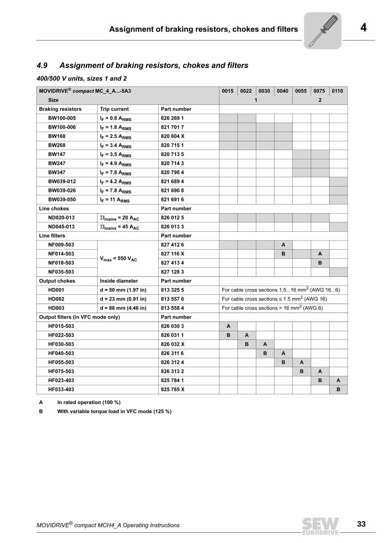
400/500 V units, sizes 1 and 2
MOVIDRIVE® compact MC_4_A...-5A3 0015 0022 0030 0040 0055 0075 0110
Size 1 2
Braking resistors Trip current Part number
BW100-005 IF = 0.8 ARMS 826 269 1
BW100-006 IF = 1.8 ARMS 821 701 7
BW168 IF = 2.5 ARMS 820 604 X
BW268 IF = 3.4 ARMS 820 715 1
BW147 IF = 3.5 ARMS 820 713 5
BW247 IF = 4.9 ARMS 820 714 3
BW347 IF = 7.8 ARMS 820 798 4
BW039-012 IF = 4.2 ARMS 821 689 4
BW039-026 IF = 7.8 ARMS 821 690 8
BW039-050 IF = 11 ARMS 821 691 6
Line chokes Part number
ND020-013 ΣImains = 20 AAC 826 012 5
ND045-013 ΣImains = 45 AAC 826 013 3
Line filters Part number
NF009-503
Vmax = 550 VAC
827 412 6 A
NF014-503 827 116 X B A
NF018-503 827 413 4 B
NF035-503 827 128 3
Output chokes Inside diameter Part number
HD001 d = 50 mm (1.97 in) 813 325 5 For cable cross sections 1.5...16 mm2 (AWG 16...6)
HD002 d = 23 mm (0.91 in) 813 557 6 For cable cross sections ≤ 1.5 mm2 (AWG 16)
HD003 d = 88 mm (4.46 in) 813 558 4 For cable cross sections > 16 mm2 (AWG 6)
Output filters (in VFC mode only) Part number
HF015-503 826 030 3 A
HF022-503 826 031 1 B A
HF030-503 826 032 X B A
HF040-503 826 311 6 B A
HF055-503 826 312 4 B A
HF075-503 826 313 2 B A
HF023-403 825 784 1 B A
HF033-403 825 785 X B
A In rated operation (100 %)
B With variable torque load in VFC mode (125 %)
4
34 MOVIDRIVE® compact MCH4_A Operating Instructions
Assignment of braking resistors, chokes and filters
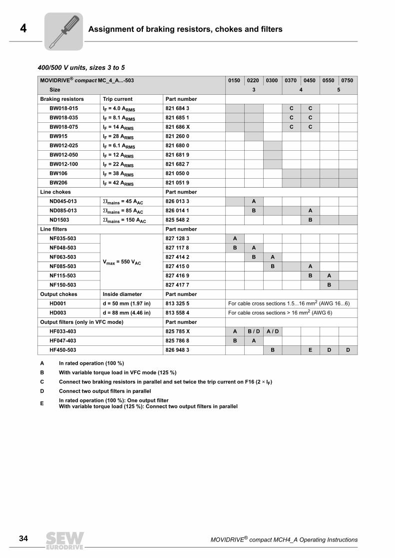
400/500 V units, sizes 3 to 5
MOVIDRIVE® compact MC_4_A...-503 0150 0220 0300 0370 0450 0550 0750
Size 3 4 5
Braking resistors Trip current Part number
BW018-015 IF = 4.0 ARMS 821 684 3 C C
BW018-035 IF = 8.1 ARMS 821 685 1 C C
BW018-075 IF = 14 ARMS 821 686 X C C
BW915 IF = 28 ARMS 821 260 0
BW012-025 IF = 6.1 ARMS 821 680 0
BW012-050 IF = 12 ARMS 821 681 9
BW012-100 IF = 22 ARMS 821 682 7
BW106 IF = 38 ARMS 821 050 0
BW206 IF = 42 ARMS 821 051 9
Line chokes Part number
ND045-013 ΣImains = 45 AAC 826 013 3 A
ND085-013 ΣImains = 85 AAC 826 014 1 B A
ND1503 ΣImains = 150 AAC 825 548 2 B
Line filters Part number
NF035-503
Vmax = 550 VAC
827 128 3 A
NF048-503 827 117 8 B A
NF063-503 827 414 2 B A
NF085-503 827 415 0 B A
NF115-503 827 416 9 B A
NF150-503 827 417 7 B
Output chokes Inside diameter Part number
HD001 d = 50 mm (1.97 in) 813 325 5 For cable cross sections 1.5...16 mm2 (AWG 16...6)
HD003 d = 88 mm (4.46 in) 813 558 4 For cable cross sections > 16 mm2 (AWG 6)
Output filters (only in VFC mode) Part number
HF033-403 825 785 X A B / D A / D
HF047-403 825 786 8 B A
HF450-503 826 948 3 B E D D
A In rated operation (100 %)
B With variable torque load in VFC mode (125 %)
C Connect two braking resistors in parallel and set twice the trip current on F16 (2 × IF)
D Connect two output filters in parallel
EIn rated operation (100 %): One output filterWith variable torque load (125 %): Connect two output filters in parallel
MOVIDRIVE® compact MCH4_A Operating Instructions 35
4Assignment of braking resistors, chokes and filters
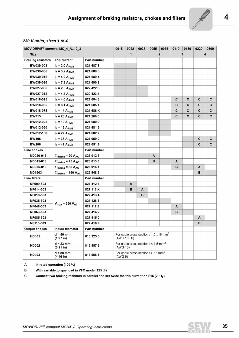
230 V units, sizes 1 to 4
MOVIDRIVE® compact MC_4_A...-2_3 0015 0022 0037 0055 0075 0110 0150 0220 0300
Size 1 2 3 4
Braking resistors Trip current Part number
BW039-003 IF = 2.0 ARMS 821 687 8
BW039-006 IF = 3.2 ARMS 821 688 6
BW039-012 IF = 4.2 ARMS 821 689 4
BW039-026 IF = 7.8 ARMS 821 690 8
BW027-006 IF = 2.5 ARMS 822 422 6
BW027-012 IF = 4.4 ARMS 822 423 4
BW018-015 IF = 4.0 ARMS 821 684 3 C C C C
BW018-035 IF = 8.1 ARMS 821 685 1 C C C C
BW018-075 IF = 14 ARMS 821 686 X C C C C
BW915 IF = 28 ARMS 821 260 0 C C C C
BW012-025 IF = 10 ARMS 821 680 0
BW012-050 IF = 19 ARMS 821 681 9
BW012-100 IF = 27 ARMS 821 682 7
BW106 IF = 38 ARMS 821 050 0 C C
BW206 IF = 42 ARMS 821 051 9 C C
Line chokes Part number
ND020-013 ΣImains = 20 AAC 826 012 5 A
ND045-013 ΣImains = 45 AAC 826 013 3 B A
ND085-013 ΣImains = 85 AAC 826 014 1 B A
ND1503 ΣImains = 150 AAC 825 548 2 B
Line filters Part number
NF009-503
Vmax = 550 VAC
827 412 6 A
NF014-503 827 116 X B A
NF018-503 827 413 4 B
NF035-503 827 128 3
NF048-503 827 117 8 A
NF063-503 827 414 2 B
NF085-503 827 415 0 A
NF115-503 827 416 9 B
Output chokes Inside diameter Part number
HD001d = 50 mm(1.97 in)
813 325 5For cable cross sections 1.5...16 mm2 (AWG 16...6)
HD002d = 23 mm(0.91 in)
813 557 6For cable cross sections ≤ 1.5 mm2
(AWG 16)
HD003d = 88 mm(4.46 in)
813 558 4For cable cross sections > 16 mm2
(AWG 6)
A In rated operation (100 %)
B With variable torque load in VFC mode (125 %)
C Connect two braking resistors in parallel and set twice the trip current on F16 (2 × IF)
4
36 MOVIDRIVE® compact MCH4_A Operating Instructions
System bus (SBus) installation
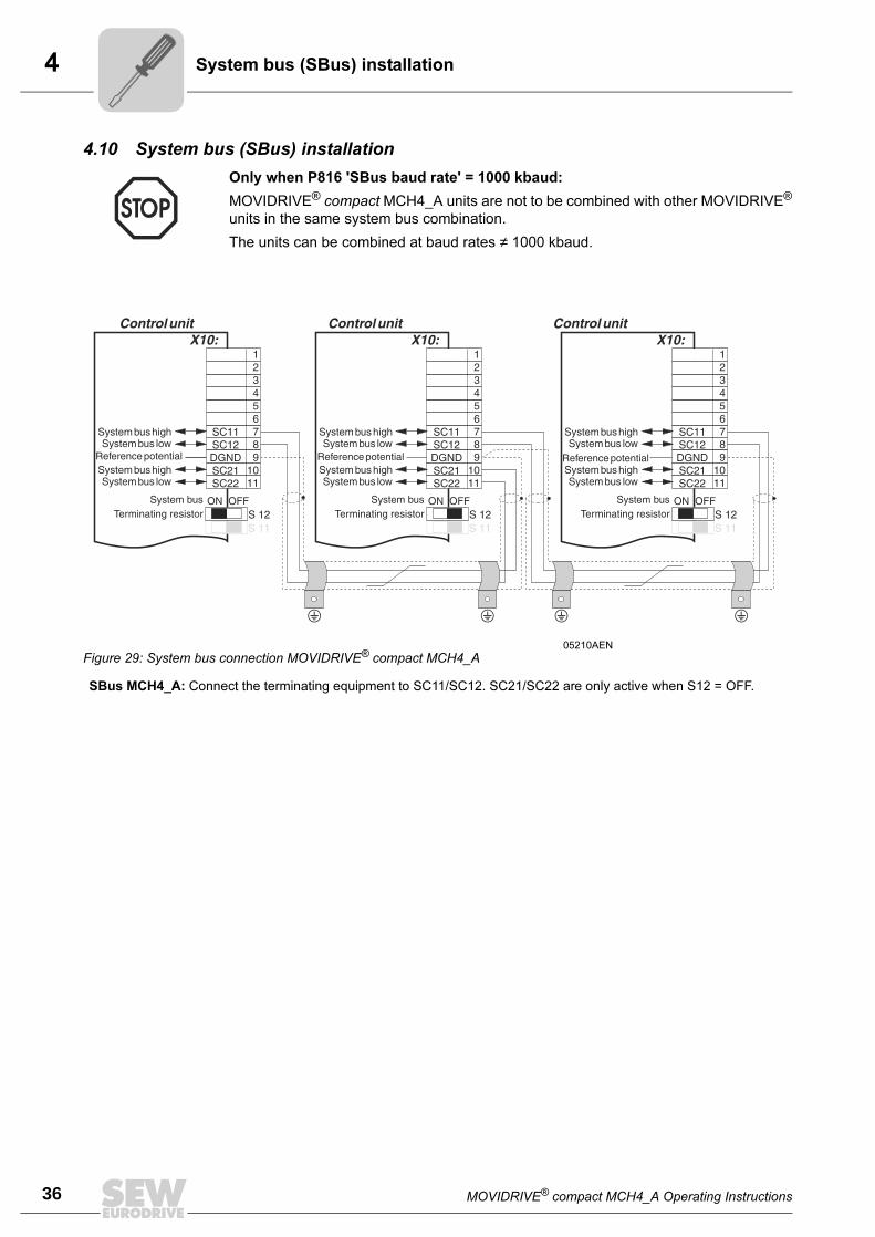
4.10 System bus (SBus) installation
Only when P816 'SBus baud rate' = 1000 kbaud:
MOVIDRIVE® compact MCH4_A units are not to be combined with other MOVIDRIVE®
units in the same system bus combination.
The units can be combined at baud rates ≠ 1000 kbaud.
05210AEN
Figure 29: System bus connection MOVIDRIVE® compact MCH4_A
SBus MCH4_A: Connect the terminating equipment to SC11/SC12. SC21/SC22 are only active when S12 = OFF.
MOVIDRIVE® compact MCH4_A Operating Instructions 37
4System bus (SBus) installation
Cable specifica-
tion
• Use a 2-core twisted and shielded copper cable (data transmission cable with shield
comprising copper braiding). The cable must meet the following specifications:
– Conductor cross section 0.75 mm2 (AWG 18)
– Cable resistance 120 Ω at 1 MHz
– Capacitance per unit length ≤ 40 pF/m (12 pF/ft) at 1 kHz
Suitable cables are CAN bus or DeviceNet cables, for example.
Shield contact • Connect the shield at either end to the electronics shield clamp of the inverter or the
master control and ensure the shield is connected over a large area. Also connect
the ends of the shield to DGND.
Line length • The permitted total cable length depends on the baud rate setting of the SBus
(P816):
– 125 kbaud → 320 m (1056 ft)
– 250 kbaud → 160 m (528 ft)
– 500 kbaud → 80 m (264 ft)
– 1000 kbaud → 40 m (132 ft)
Terminating
resistor
• Switch on the system bus terminating resistor (S12 = ON) at the start and finish of
the system bus connection. Switch off the terminating resistor on the other units (S12
= OFF).
• There must not be any potential displacement between the units connected using the
SBus. Take suitable measures to avoid a potential displacement, e.g. by connecting
the unit ground connectors using a separate lead. Do not use the shield of the SBus
cable for equipotential bonding!
4
38 MOVIDRIVE® compact MCH4_A Operating Instructions
Connection of option USS21A (RS-232 and RS-485)
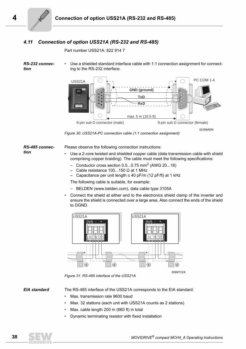
4.11 Connection of option USS21A (RS-232 and RS-485)
Part number USS21A: 822 914 7
RS-232 connec-
tion
• Use a shielded standard interface cable with 1:1 connection assignment for connect-
ing to the RS-232 interface.
RS-485 connec-
tion
Please observe the following connection instructions:
• Use a 2-core twisted and shielded copper cable (data transmission cable with shield
comprising copper braiding). The cable must meet the following specifications:
– Conductor cross section 0.5...0.75 mm2 (AWG 20...18)
– Cable resistance 100...150 Ω at 1 MHz
– Capacitance per unit length ≤ 40 pF/m (12 pF/ft) at 1 kHz
The following cable is suitable, for example:
– BELDEN (www.belden.com), data cable type 3105A
• Connect the shield at either end to the electronics shield clamp of the inverter and
ensure the shield is connected over a large area. Also connect the ends of the shield
to DGND.
EIA standard The RS-485 interface of the USS21A corresponds to the EIA standard:
• Max. transmission rate 9600 baud
• Max. 32 stations (each unit with USS21A counts as 2 stations)
• Max. cable length 200 m (660 ft) in total
• Dynamic terminating resistor with fixed installation
02399AEN
Figure 30: USS21A-PC connection cable (1:1 connection assignment)
RxD
TxD2233
55
max. 5 m (16.5 ft)
USS21A PC COM 1-4
55
3322 2
3
55
32
9-pin sub D connector (female)9-pin sub D connector (male)
GND (ground)
00997CXX
Figure 31: RS-485 interface of the USS21A
+ +- -0V5 0V5USS21A USS21A
123 123
MOVIDRIVE® compact MCH4_A Operating Instructions 39
4Connection of motor encoder and external encoder
4.12 Connection of motor encoder and external encoder
The 'SEW Encoder Systems' manual contains detailed information. This manual can be
obtained from SEW.
General installa-
tion notes
• Max. line length (inverter-encoder): 100 m (330 ft) with a capacitance per unit length
≤ 120 nF/km (193 nF/mile).
• Core cross section
– Hiperface encoder, sin/cos encoder and TTL sensor with 5 VDC supply (via
DWI11A): 0.25...0.5 mm2 (AWG 23...20)
– TTL sensor with 12...24 VDC supply: 0.5 mm2 (AWG 20)
• If you cut off a core of the encoder cable: Isolate the cut-off end of the core.
• Use shielded cables with twisted pairs of insulated conductors and connect the shield
at both ends:
– to the encoder in the cable screw fitting or in the encoder plug
– to the inverter in the housing of the sub D plug and to the electronics shield clamp
of the inverter
• Use encoder plugs and sub D plugs with a metal housing.
• Route the encoder cable separately from the power cables.
• Encoder with cable gland: Please note permitted diameter of the encoder cable for
correct function of cable gland.
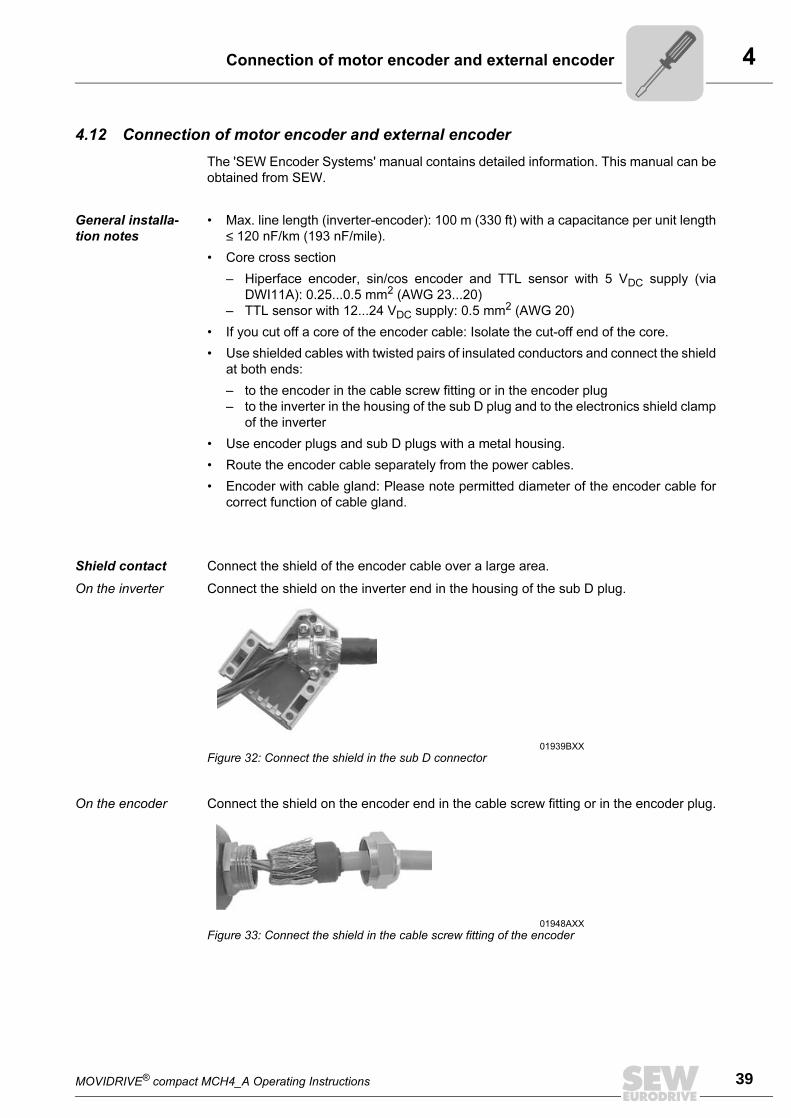
Shield contact Connect the shield of the encoder cable over a large area.
On the inverter Connect the shield on the inverter end in the housing of the sub D plug.
On the encoder Connect the shield on the encoder end in the cable screw fitting or in the encoder plug.
01939BXX
Figure 32: Connect the shield in the sub D connector
01948AXX
Figure 33: Connect the shield in the cable screw fitting of the encoder
4
40 MOVIDRIVE® compact MCH4_A Operating Instructions
Connection of motor encoder and external encoder
Pre-fabricated
cables
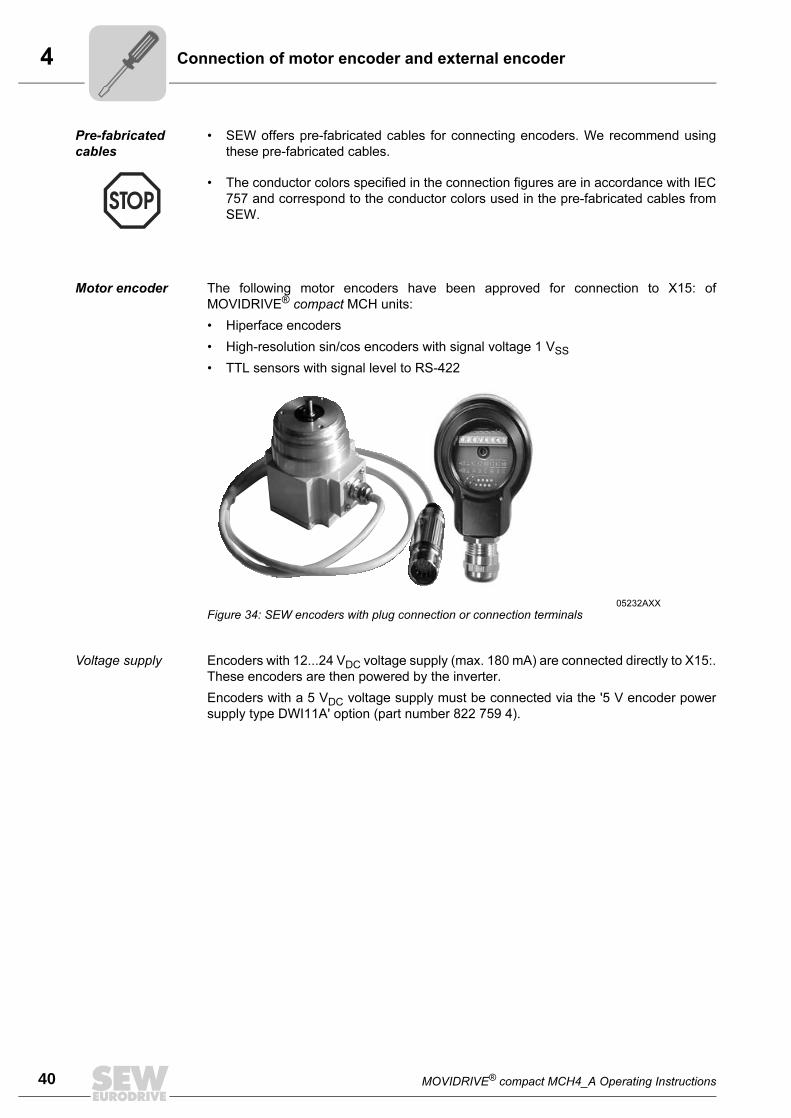
• SEW offers pre-fabricated cables for connecting encoders. We recommend using
these pre-fabricated cables.
Motor encoder The following motor encoders have been approved for connection to X15: of
MOVIDRIVE® compact MCH units:
• Hiperface encoders
• High-resolution sin/cos encoders with signal voltage 1 VSS
• TTL sensors with signal level to RS-422
Voltage supply Encoders with 12...24 VDC voltage supply (max. 180 mA) are connected directly to X15:.
These encoders are then powered by the inverter.
Encoders with a 5 VDC voltage supply must be connected via the '5 V encoder power
supply type DWI11A' option (part number 822 759 4).
• The conductor colors specified in the connection figures are in accordance with IEC
757 and correspond to the conductor colors used in the pre-fabricated cables from
SEW.
05232AXX
Figure 34: SEW encoders with plug connection or connection terminals
MOVIDRIVE® compact MCH4_A Operating Instructions 41
4Connection of motor encoder and external encoder
Hiperface encod-
ers
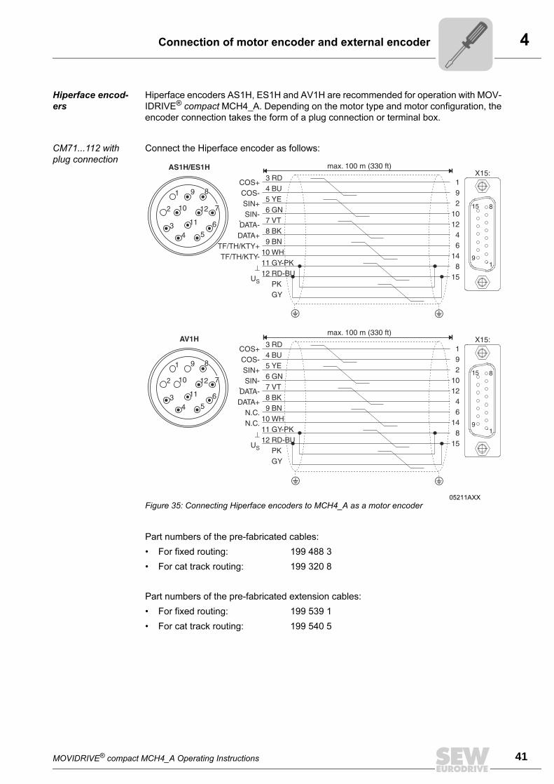
Hiperface encoders AS1H, ES1H and AV1H are recommended for operation with MOV-
IDRIVE® compact MCH4_A. Depending on the motor type and motor configuration, the
encoder connection takes the form of a plug connection or terminal box.
CM71...112 with
plug connection
Connect the Hiperface encoder as follows:
Part numbers of the pre-fabricated cables:
• For fixed routing: 199 488 3
• For cat track routing: 199 320 8
Part numbers of the pre-fabricated extension cables:
• For fixed routing: 199 539 1
• For cat track routing: 199 540 5
05211AXX
Figure 35: Connecting Hiperface encoders to MCH4_A as a motor encoder
4
42 MOVIDRIVE® compact MCH4_A Operating Instructions
Connection of motor encoder and external encoder
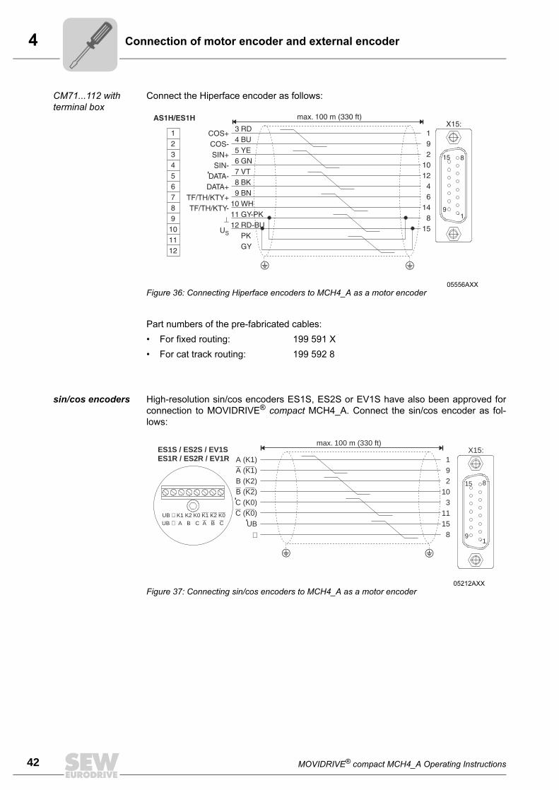
CM71...112 with
terminal box
Connect the Hiperface encoder as follows:
Part numbers of the pre-fabricated cables:
• For fixed routing: 199 591 X
• For cat track routing: 199 592 8
sin/cos encoders High-resolution sin/cos encoders ES1S, ES2S or EV1S have also been approved for
connection to MOVIDRIVE® compact MCH4_A. Connect the sin/cos encoder as fol-
lows:
05556AXX
Figure 36: Connecting Hiperface encoders to MCH4_A as a motor encoder
05212AXX
Figure 37: Connecting sin/cos encoders to MCH4_A as a motor encoder
ES1S / ES2S / EV1SES1R / ES2R / EV1R
UB K1 K2 K0⊥ K1 K2 K0UB A B C⊥ A B C
192
103
1115
81
8
9
15
X15:max. 100 m (330 ft)
A (K1)( )
B (K2)( )
C (K0)( )UB
A K1
B K2
C K0
⊥
MOVIDRIVE® compact MCH4_A Operating Instructions 43
4Connection of motor encoder and external encoder
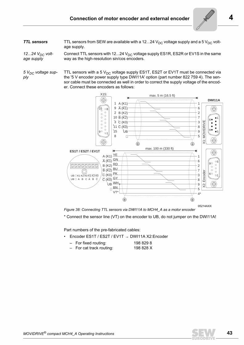
TTL sensors TTL sensors from SEW are available with a 12...24 VDC voltage supply and a 5 VDC volt-
age supply.
12...24 VDC volt-
age supply
Connect TTL sensors with 12...24 VDC voltage supply ES1R, ES2R or EV1S in the same
way as the high-resolution sin/cos encoders.
5 VDC voltage sup-
ply
TTL sensors with a 5 VDC voltage supply ES1T, ES2T or EV1T must be connected via
the '5 V encoder power supply type DWI11A' option (part number 822 759 4). The sen-
sor cable must be connected as well in order to correct the supply voltage of the encod-
er. Connect these encoders as follows:
* Connect the sensor line (VT) on the encoder to UB, do not jumper on the DWI11A!
Part numbers of the pre-fabricated cables:
• Encoder ES1T / ES2T / EV1T → DWI11A X2:Encoder
– For fixed routing: 198 829 8
– For cat track routing: 198 828 X
05214AXX
Figure 38: Connecting TTL sensors via DWI11A to MCH4_A as a motor encoder
1
5
5
1
6
9
9
6
DWI11A
X2:
Enc
oder
X1:
MO
VID
RIV
E
max. 5 m (16.5 ft)
max. 100 m (330 ft)ES1T / ES2T / EV1T
162738954*
YEGNRDBUPKGYWHBNVT*
16273895
A (K1)( )
B (K2)( )
C (K0)( )UB
A K1
B K2
C K0
⊥
A (K1)( )
B (K2)( )
C (K0)( )UB
A K1
B K2
C K0
⊥
19210311158
UB K1 K2 K0⊥ K1 K2 K0UB A B C⊥ A B C
1
8
9
15
X15:
4
44 MOVIDRIVE® compact MCH4_A Operating Instructions
Connection of motor encoder and external encoder
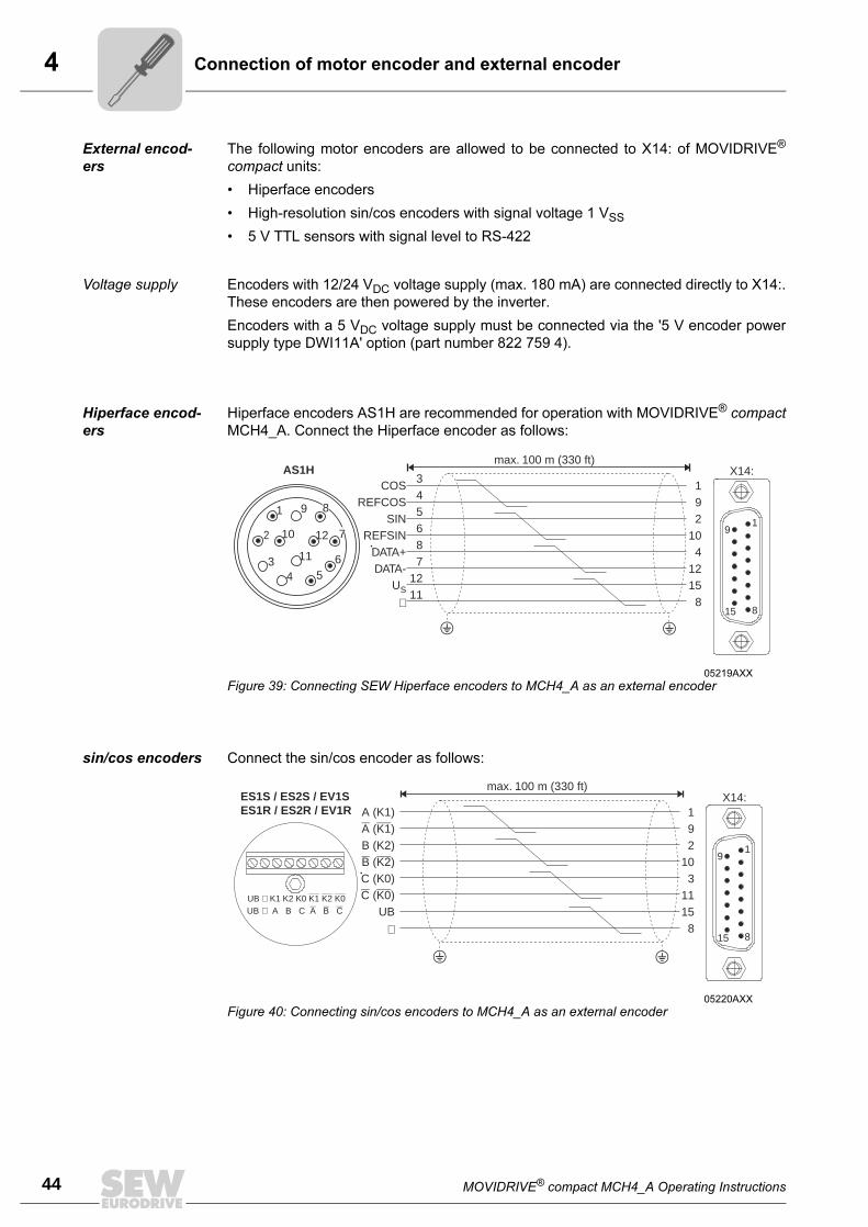
External encod-
ers
The following motor encoders are allowed to be connected to X14: of MOVIDRIVE®
compact units:
• Hiperface encoders
• High-resolution sin/cos encoders with signal voltage 1 VSS
• 5 V TTL sensors with signal level to RS-422
Voltage supply Encoders with 12/24 VDC voltage supply (max. 180 mA) are connected directly to X14:.
These encoders are then powered by the inverter.
Encoders with a 5 VDC voltage supply must be connected via the '5 V encoder power
supply type DWI11A' option (part number 822 759 4).
Hiperface encod-
ers
Hiperface encoders AS1H are recommended for operation with MOVIDRIVE® compact
MCH4_A. Connect the Hiperface encoder as follows:
sin/cos encoders Connect the sin/cos encoder as follows:
05219AXX
Figure 39: Connecting SEW Hiperface encoders to MCH4_A as an external encoder
X14:
1
8
9
15
192
104
1215
8
max. 100 m (330 ft)
COSREFCOS
SINREFSIN
DATA+DATA-
US
⊥
345687
1211
AS1H
34 5
6
9
10
11
12
1
2 7
8
05220AXX
Figure 40: Connecting sin/cos encoders to MCH4_A as an external encoder
ES1S / ES2S / EV1SES1R / ES2R / EV1R
UB K1 K2 K0⊥ K1 K2 K0UB A B C⊥ A B C
192
103
1115
8
X14:max. 100 m (330 ft)
A (K1)( )
B (K2)( )
C (K0)( )UB
A K1
B K2
C K0
⊥
1
8
9
15
MOVIDRIVE® compact MCH4_A Operating Instructions 45
4Connection of motor encoder and external encoder
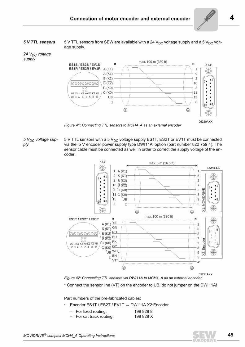
5 V TTL sensors 5 V TTL sensors from SEW are available with a 24 VDC voltage supply and a 5 VDC volt-
age supply.
24 VDC voltage
supply
5 VDC voltage sup-
ply
5 V TTL sensors with a 5 VDC voltage supply ES1T, ES2T or EV1T must be connected
via the '5 V encoder power supply type DWI11A' option (part number 822 759 4). The
sensor cable must be connected as well in order to correct the supply voltage of the en-
coder.
* Connect the sensor line (VT) on the encoder to UB, do not jumper on the DWI11A!
Part numbers of the pre-fabricated cables:
• Encoder ES1T / ES2T / EV1T → DWI11A X2:Encoder
– For fixed routing: 198 829 8
– For cat track routing: 198 828 X
05220AXX
Figure 41: Connecting TTL sensors to MCH4_A as an external encoder
ES1S / ES2S / EV1SES1R / ES2R / EV1R
UB K1 K2 K0⊥ K1 K2 K0UB A B C⊥ A B C
192
103
1115
8
X14:max. 100 m (330 ft)
A (K1)( )
B (K2)( )
C (K0)( )UB
A K1
B K2
C K0
⊥
1
8
9
15
05221AXX
Figure 42: Connecting TTL sensors via DWI11A to MCH4_A as an external encoder
1
5
5
1
6
9
9
6
DWI11A
X2:
Enc
oder
X1:
MO
VID
RIV
E
max. 5 m (16.5 ft)
max. 100 m (330 ft)ES1T / ES2T / EV1T
162738954*
YEGNRDBUPKGYWHBNVT*
16273895
A (K1)( )
B (K2)( )
C (K0)( )UB
A K1
B K2
C K0
⊥
A (K1)( )
B (K2)( )
C (K0)( )UB
A K1
B K2
C K0
⊥
19210311158
UB K1 K2 K0⊥ K1 K2 K0UB A B C⊥ A B C
X14:
1
8
9
15
4
46 MOVIDRIVE® compact MCH4_A Operating Instructions
Connection of motor encoder and external encoder
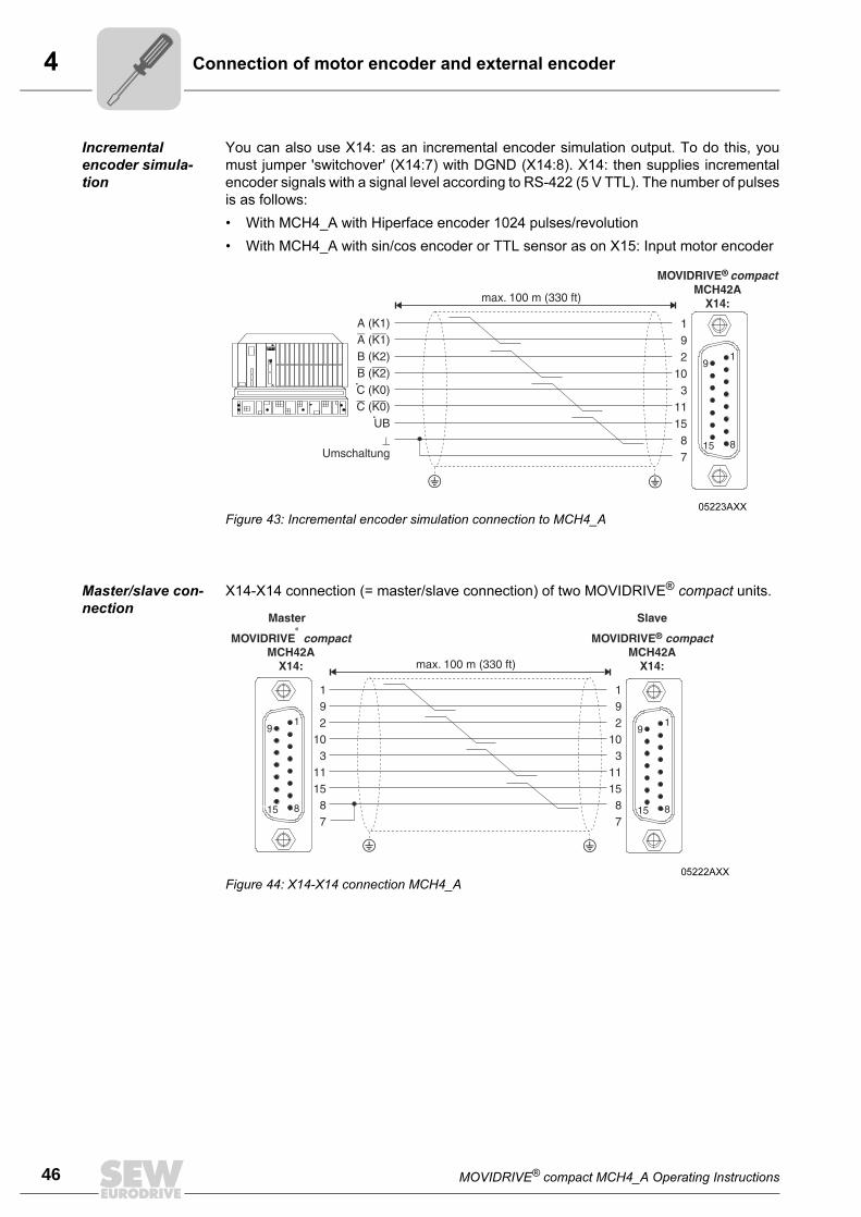
Incremental
encoder simula-
tion
You can also use X14: as an incremental encoder simulation output. To do this, you
must jumper 'switchover' (X14:7) with DGND (X14:8). X14: then supplies incremental
encoder signals with a signal level according to RS-422 (5 V TTL). The number of pulses
is as follows:
• With MCH4_A with Hiperface encoder 1024 pulses/revolution
• With MCH4_A with sin/cos encoder or TTL sensor as on X15: Input motor encoder
Master/slave con-
nection
X14-X14 connection (= master/slave connection) of two MOVIDRIVE® compact units.
05223AXX
Figure 43: Incremental encoder simulation connection to MCH4_A
05222AXX
Figure 44: X14-X14 connection MCH4_A
MOVIDRIVE® compact MCH4_A Operating Instructions 47
5General startup instructions
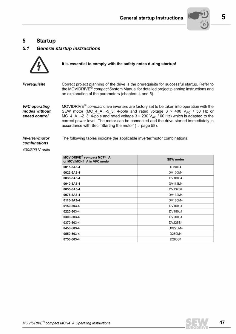
5 Startup
5.1 General startup instructions
Prerequisite Correct project planning of the drive is the prerequisite for successful startup. Refer to
the MOVIDRIVE® compact System Manual for detailed project planning instructions and
an explanation of the parameters (chapters 4 and 5).
VFC operating
modes without
speed control
MOVIDRIVE® compact drive inverters are factory set to be taken into operation with the
SEW motor (MC_4_A...-5_3: 4-pole and rated voltage 3 × 400 VAC / 50 Hz or
MC_4_A...-2_3: 4-pole and rated voltage 3 × 230 VAC / 60 Hz) which is adapted to the
correct power level. The motor can be connected and the drive started immediately in
accordance with Sec. 'Starting the motor' (→ page 58).
Inverter/motor
combinations
The following tables indicate the applicable inverter/motor combinations.
400/500 V units
It is essential to comply with the safety notes during startup!
MOVIDRIVE® compact MCF4_A
or MCV/MCH4_A in VFC modeSEW motor
0015-5A3-4 DT90L4
0022-5A3-4 DV100M4
0030-5A3-4 DV100L4
0040-5A3-4 DV112M4
0055-5A3-4 DV132S4
0075-5A3-4 DV132M4
0110-5A3-4 DV160M4
0150-503-4 DV160L4
0220-503-4 DV180L4
0300-503-4 DV200L4
0370-503-4 DV225S4
0450-503-4 DV225M4
0550-503-4 D250M4
0750-503-4 D280S4
00
I
5
48 MOVIDRIVE® compact MCH4_A Operating Instructions
General startup instructions
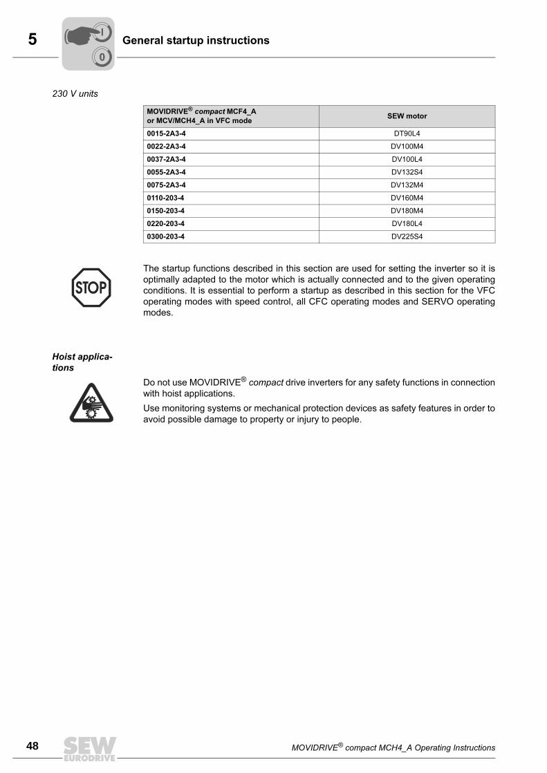
230 V units
Hoist applica-
tions
MOVIDRIVE® compact MCF4_A
or MCV/MCH4_A in VFC modeSEW motor
0015-2A3-4 DT90L4
0022-2A3-4 DV100M4
0037-2A3-4 DV100L4
0055-2A3-4 DV132S4
0075-2A3-4 DV132M4
0110-203-4 DV160M4
0150-203-4 DV180M4
0220-203-4 DV180L4
0300-203-4 DV225S4
The startup functions described in this section are used for setting the inverter so it is
optimally adapted to the motor which is actually connected and to the given operating
conditions. It is essential to perform a startup as described in this section for the VFC
operating modes with speed control, all CFC operating modes and SERVO operating
modes.
Do not use MOVIDRIVE® compact drive inverters for any safety functions in connection
with hoist applications.
Use monitoring systems or mechanical protection devices as safety features in order to
avoid possible damage to property or injury to people.
00
I
MOVIDRIVE® compact MCH4_A Operating Instructions 49
5Preliminary work and resources
5.2 Preliminary work and resources
• Check the installation.
• Take suitable measures to prevent the motor starting up inadvertently. Further-
more, additional safety precautions must be taken depending on the application in
order to avoid endangering people and machinery.
Suitable measures are:
– With MCF/MCV/MCS4_A: Connect terminal X10:9 '/CONTROL. INHIBIT' to
DGND.
– With MCH4_A: Disconnect the electronics terminal block X11.
• For startup with the DBG11B keypad:
Connect the DBG11B keypad to the TERMINAL option slot.
• For startup with a PC and MOVITOOLS:
Connect the USS21A option to the TERMINAL option slot and use an interface cable
(RS-232) to connect it to the PC. MOVIDRIVE® and the PC must be de-energized
when you do this, otherwise undefined states may be adopted. Then switch on both
units. Install MOVITOOLS on the PC if you have not already done so. Start the pro-
gram.
• Switch on the power supply and the 24 V supply, if necessary.
If you are using the DBG11B keypad, the following message appears for about 13 s:
• Undertake the correct preliminary parameter setting (e.g. factory setting).
• Check the set terminal assignment (→ P60_).
SELFTEST
MOVIDRIVE
Startup automatically changes a group of parameter values. The parameter descrip-
tion P700 'Operating modes' explains which parameters are affected by this step. Refer
to the MOVIDRIVE® compact System Manual, Sec. 4 'Parameters', for a parameter de-
scription.
00
I
5
50 MOVIDRIVE® compact MCH4_A Operating Instructions
Startup with the DBG11B keypad
5.3 Startup with the DBG11B keypad
General informa-
tion
Startup with the DBG11B keypad is possible with MCF and MCV/MCH in VFC op-
erating modes only. Startup in CFC and SERVO operating modes is possible using the
MOVITOOLS software only.
Data required The following data are required for successful startup:
• Motor type (SEW motor or non-SEW motor)
• Motor data
– Rated voltage and rated frequency.
– In addition, with a non-SEW motor: Rated current, rated power, power factor cosϕand rated speed.
• Power supply voltage
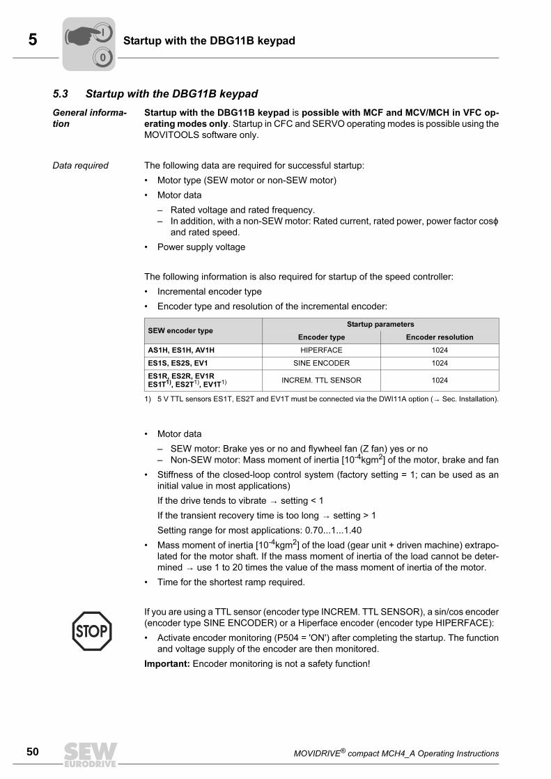
The following information is also required for startup of the speed controller:
• Incremental encoder type
• Encoder type and resolution of the incremental encoder:
• Motor data
– SEW motor: Brake yes or no and flywheel fan (Z fan) yes or no
– Non-SEW motor: Mass moment of inertia [10-4kgm2] of the motor, brake and fan
• Stiffness of the closed-loop control system (factory setting = 1; can be used as an
initial value in most applications)
If the drive tends to vibrate → setting < 1
If the transient recovery time is too long → setting > 1
Setting range for most applications: 0.70...1...1.40
• Mass moment of inertia [10-4kgm2] of the load (gear unit + driven machine) extrapo-
lated for the motor shaft. If the mass moment of inertia of the load cannot be deter-
mined → use 1 to 20 times the value of the mass moment of inertia of the motor.
• Time for the shortest ramp required.
SEW encoder typeStartup parameters
Encoder type Encoder resolution
AS1H, ES1H, AV1H HIPERFACE 1024
ES1S, ES2S, EV1 SINE ENCODER 1024
ES1R, ES2R, EV1RES1T1), ES2T1), EV1T1)
1) 5 V TTL sensors ES1T, ES2T and EV1T must be connected via the DWI11A option (→ Sec. Installation).
INCREM. TTL SENSOR 1024
If you are using a TTL sensor (encoder type INCREM. TTL SENSOR), a sin/cos encoder
(encoder type SINE ENCODER) or a Hiperface encoder (encoder type HIPERFACE):
• Activate encoder monitoring (P504 = 'ON') after completing the startup. The function
and voltage supply of the encoder are then monitored.
Important: Encoder monitoring is not a safety function!
00
I
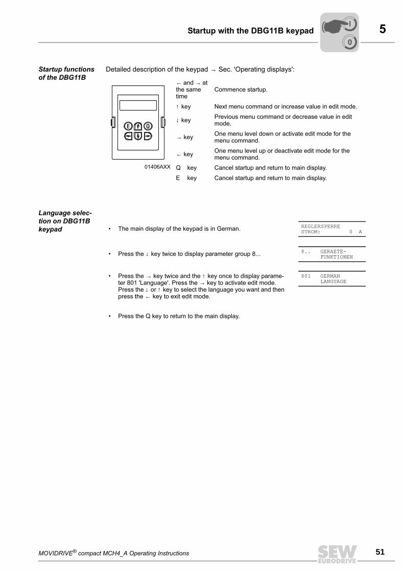
MOVIDRIVE® compact MCH4_A Operating Instructions 51
5Startup with the DBG11B keypad
Startup functions
of the DBG11B
Detailed description of the keypad → Sec. 'Operating displays':
Language selec-
tion on DBG11B
keypad
01406AXX
← and → at the same time
Commence startup.
↑ key Next menu command or increase value in edit mode.
↓ keyPrevious menu command or decrease value in edit mode.
→ keyOne menu level down or activate edit mode for the menu command.
← keyOne menu level up or deactivate edit mode for the menu command.
Q key Cancel startup and return to main display.
E key Cancel startup and return to main display.
E Q
• The main display of the keypad is in German. REGLERSPERRESTROM: 0 A
• Press the ↓ key twice to display parameter group 8... 8.. GERAETE-FUNKTIONEN
• Press the → key twice and the ↑ key once to display parame-ter 801 'Language'. Press the → key to activate edit mode. Press the ↓ or ↑ key to select the language you want and then press the ← key to exit edit mode.
801 GERMANLANGUAGE
• Press the Q key to return to the main display.
00
I
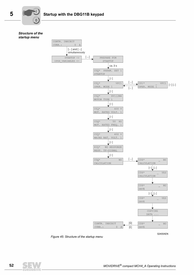
5
52 MOVIDRIVE® compact MCH4_A Operating Instructions
Startup with the DBG11B keypad
Structure of the
startup menu
02400AEN
Figure 45: Structure of the startup menu
[ ]→
[ ]→
[ ]→
[ ]←
[E]
[Q]
ca. 3 s
[ ]↑
[ ] [ ]↑ ↓
[ ]↑
[ ]↑
[ ]↑
[ ]↑
[ ]↑
[ ]↑
[ ]↓
[ ]↓
[ ]↑
[ ]↑
C0 * PARAM. SET 1
STARTUP
0
C01* _ VFC1
OPER. MODE 1
C0 * VFC1
OPER. MODE 1
1
C0 * DV112M4
MOTOR TYPE 1
2
C0 * 400 V
MOT. RATED VOLT. 1
3
C0 * 50 HZ
MOT. RATED FREQ. 1
4
C0 * 400 V
MAINS RAT. VOLT. 1
5
83 * NO RESPONSE
RESP. TF-SIGNAL
5
C0 * NO
CALCULATION
6 C06* _ NO
CALCULATION
C08* _ NO
SAVE
C08* _ YES
SAVE
C08* _ NO
SAVE
C06* _ YES
CALCULATION
[ ] and [ ]simultaneously← →
PREPARE FOR
STARTUP
COPYING
DATA ...
STARTUP ->
IPOS_VARIABLES <-
CONTR. INHIBIT
CURR.: 0 A
CONTR. INHIBIT
CURR.: 0 A
00
I
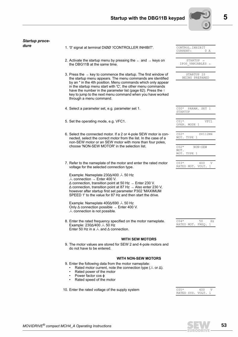
MOVIDRIVE® compact MCH4_A Operating Instructions 53
5Startup with the DBG11B keypad
Startup proce-
dure1. '0' signal at terminal DIØØ '/CONTROLLER INHIBIT'. CONTROL.INHIBIT
CURRENT: 0 A
2. Activate the startup menu by pressing the ← and → keys on the DBG11B at the same time.
STARTUP →IPOS_VARIABLES ←
3. Press the → key to commence the startup. The first window of the startup menu appears. The menu commands are identified by an * in the 4th position. Menu commands which only appear in the startup menu start with 'C', the other menu commands have the number in the parameter list (page 62). Press the ↑ key to jump to the next menu command when you have worked through a menu command.
STARTUP ISBEING PREPARED
4. Select a parameter set, e.g. parameter set 1. C00* PARAM. SET 1STARTUP
5. Set the operating mode, e.g. VFC1. C01* VFC1OPER. MODE 1
6. Select the connected motor. If a 2 or 4-pole SEW motor is con-nected, select the correct motor from the list. In the case of a non-SEW motor or an SEW motor with more than four poles, choose 'NON-SEW MOTOR' in the selection list.
C02* DV112M4MOT. TYPE 1
C02* NON-SEW MOT.MOT. TYPE 1
7. Refer to the nameplate of the motor and enter the rated motor voltage for the selected connection type.
Example: Nameplate 230∆/400 50 Hz connection → Enter 400 V.∆ connection, transition point at 50 Hz → Enter 230 V.∆ connection, transition point at 87 Hz → Also enter 230 V, however after startup first set parameter P302 'MAXIMUM SPEED 1' to the value for 87 Hz and then start the drive.
Example: Nameplate 400∆/690 50 HzOnly ∆ connection possible → Enter 400 V. connection is not possible.
C03* 400 VRATED MOT. VOLT. 1
8. Enter the rated frequency specified on the motor nameplate.Example: 230∆/400 50 HzEnter 50 Hz in a and ∆ connection.
C04* 50 HzRATED MOT. FREQ. 1
WITH SEW MOTORS
9. The motor values are stored for SEW 2 and 4-pole motors and do not have to be entered.
WITH NON-SEW MOTORS
9. Enter the following data from the motor nameplate:• Rated motor current, note the connection type ( or ∆).• Rated power of the motor• Power factor cos ϕ• Rated speed of the motor
10. Enter the rated voltage of the supply system C05* 400 VRATED SYS. VOLT. 1
00
I
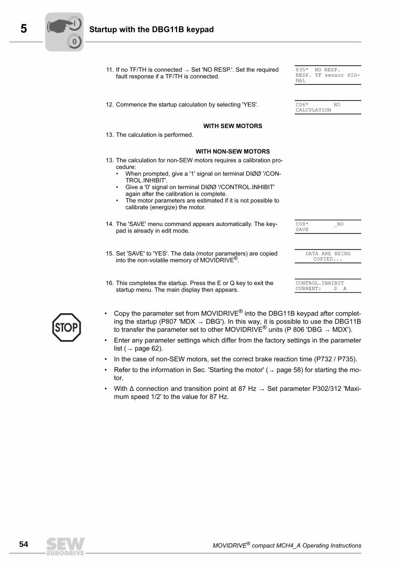
5
54 MOVIDRIVE® compact MCH4_A Operating Instructions
Startup with the DBG11B keypad
11. If no TF/TH is connected → Set 'NO RESP.'. Set the required fault response if a TF/TH is connected.
835* NO RESP.RESP. TF sensor SIG-NAL
12. Commence the startup calculation by selecting 'YES'. C06* NOCALCULATION
WITH SEW MOTORS
13. The calculation is performed.
WITH NON-SEW MOTORS
13. The calculation for non-SEW motors requires a calibration pro-cedure:• When prompted, give a '1' signal on terminal DIØØ '/CON-
TROL.INHIBIT'.• Give a '0' signal on terminal DIØØ '/CONTROL.INHIBIT'
again after the calibration is complete.• The motor parameters are estimated if it is not possible to
calibrate (energize) the motor.
14. The 'SAVE' menu command appears automatically. The key-pad is already in edit mode.
C08* _NOSAVE
15. Set 'SAVE' to 'YES'. The data (motor parameters) are copied into the non-volatile memory of MOVIDRIVE®.
DATA ARE BEINGCOPIED...
16. This completes the startup. Press the E or Q key to exit the startup menu. The main display then appears.
CONTROL.INHIBITCURRENT: 0 A
• Copy the parameter set from MOVIDRIVE® into the DBG11B keypad after complet-
ing the startup (P807 'MDX → DBG'). In this way, it is possible to use the DBG11B
to transfer the parameter set to other MOVIDRIVE® units (P 806 'DBG → MDX').
• Enter any parameter settings which differ from the factory settings in the parameter
list (→ page 62).
• In the case of non-SEW motors, set the correct brake reaction time (P732 / P735).
• Refer to the information in Sec. 'Starting the motor' (→ page 58) for starting the mo-
tor.
• With ∆ connection and transition point at 87 Hz → Set parameter P302/312 'Maxi-
mum speed 1/2' to the value for 87 Hz.
00
I
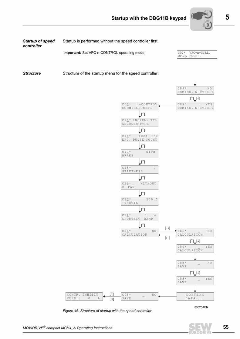
MOVIDRIVE® compact MCH4_A Operating Instructions 55
5Startup with the DBG11B keypad
Startup of speed
controller
Startup is performed without the speed controller first.
Structure Structure of the startup menu for the speed controller:
Important: Set VFC-n-CONTROL operating mode. C01* VFC-n-CTRL.OPER. MODE 1
03025AEN
Figure 46: Structure of startup with the speed controller
00
I
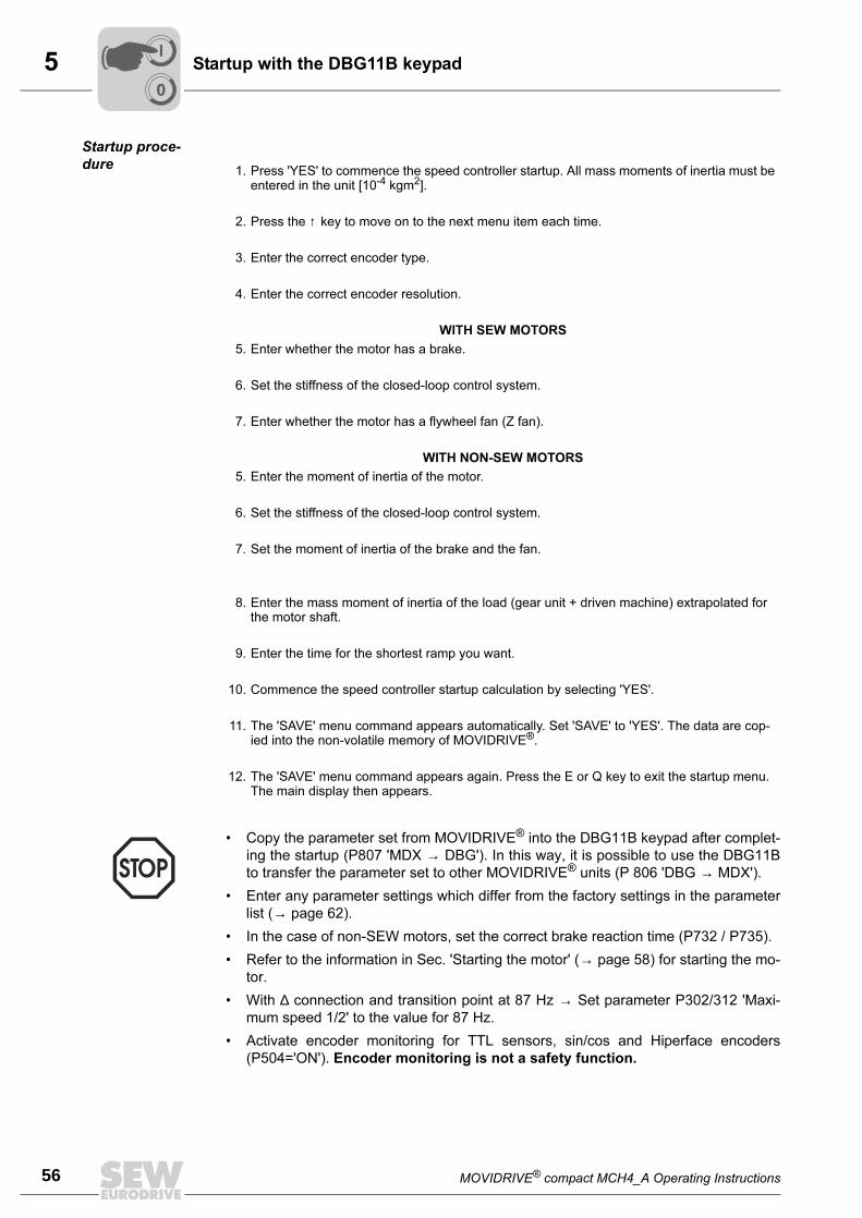
5
56 MOVIDRIVE® compact MCH4_A Operating Instructions
Startup with the DBG11B keypad
Startup proce-
dure1. Press 'YES' to commence the speed controller startup. All mass moments of inertia must be
entered in the unit [10-4 kgm2].
2. Press the ↑ key to move on to the next menu item each time.
3. Enter the correct encoder type.
4. Enter the correct encoder resolution.
WITH SEW MOTORS
5. Enter whether the motor has a brake.
6. Set the stiffness of the closed-loop control system.
7. Enter whether the motor has a flywheel fan (Z fan).
WITH NON-SEW MOTORS
5. Enter the moment of inertia of the motor.
6. Set the stiffness of the closed-loop control system.
7. Set the moment of inertia of the brake and the fan.
8. Enter the mass moment of inertia of the load (gear unit + driven machine) extrapolated for the motor shaft.
9. Enter the time for the shortest ramp you want.
10. Commence the speed controller startup calculation by selecting 'YES'.
11. The 'SAVE' menu command appears automatically. Set 'SAVE' to 'YES'. The data are cop-ied into the non-volatile memory of MOVIDRIVE®.
12. The 'SAVE' menu command appears again. Press the E or Q key to exit the startup menu. The main display then appears.
• Copy the parameter set from MOVIDRIVE® into the DBG11B keypad after complet-
ing the startup (P807 'MDX → DBG'). In this way, it is possible to use the DBG11B
to transfer the parameter set to other MOVIDRIVE® units (P 806 'DBG → MDX').
• Enter any parameter settings which differ from the factory settings in the parameter
list (→ page 62).
• In the case of non-SEW motors, set the correct brake reaction time (P732 / P735).
• Refer to the information in Sec. 'Starting the motor' (→ page 58) for starting the mo-
tor.
• With ∆ connection and transition point at 87 Hz → Set parameter P302/312 'Maxi-
mum speed 1/2' to the value for 87 Hz.
• Activate encoder monitoring for TTL sensors, sin/cos and Hiperface encoders
(P504='ON'). Encoder monitoring is not a safety function.
00
I
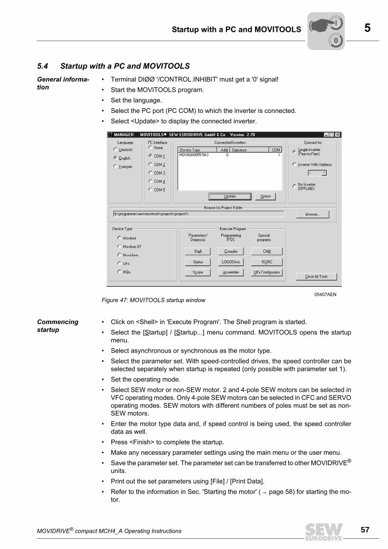
MOVIDRIVE® compact MCH4_A Operating Instructions 57
5Startup with a PC and MOVITOOLS
5.4 Startup with a PC and MOVITOOLS
General informa-
tion
• Terminal DIØØ '/CONTROL.INHIBIT' must get a '0' signal!
• Start the MOVITOOLS program.
• Set the language.
• Select the PC port (PC COM) to which the inverter is connected.
• Select <Update> to display the connected inverter.
Commencing
startup
• Click on <Shell> in 'Execute Program'. The Shell program is started.
• Select the [Startup] / [Startup...] menu command. MOVITOOLS opens the startup
menu.
• Select asynchronous or synchronous as the motor type.
• Select the parameter set. With speed-controlled drives, the speed controller can be
selected separately when startup is repeated (only possible with parameter set 1).
• Set the operating mode.
• Select SEW motor or non-SEW motor. 2 and 4-pole SEW motors can be selected in
VFC operating modes. Only 4-pole SEW motors can be selected in CFC and SERVO
operating modes. SEW motors with different numbers of poles must be set as non-
SEW motors.
• Enter the motor type data and, if speed control is being used, the speed controller
data as well.
• Press <Finish> to complete the startup.
• Make any necessary parameter settings using the main menu or the user menu.
• Save the parameter set. The parameter set can be transferred to other MOVIDRIVE®
units.
• Print out the set parameters using [File] / [Print Data].
• Refer to the information in Sec. 'Starting the motor' (→ page 58) for starting the mo-
tor.
05407AEN
Figure 47: MOVITOOLS startup window
00
I
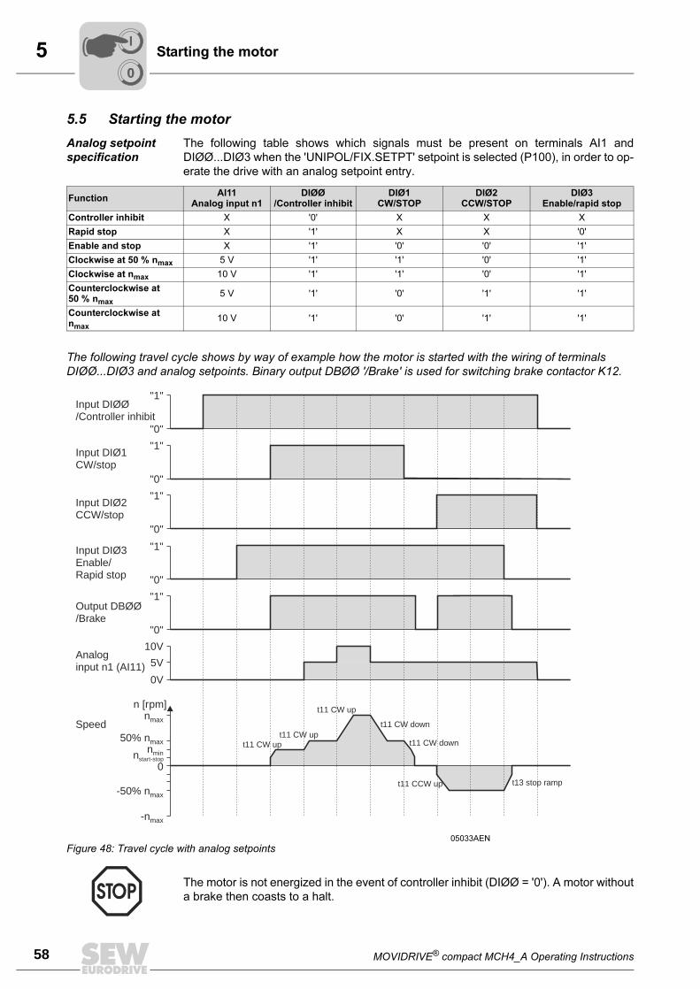
5
58 MOVIDRIVE® compact MCH4_A Operating Instructions
Starting the motor
5.5 Starting the motor
Analog setpoint
specification
The following table shows which signals must be present on terminals AI1 and
DIØØ...DIØ3 when the 'UNIPOL/FIX.SETPT' setpoint is selected (P100), in order to op-
erate the drive with an analog setpoint entry.
The following travel cycle shows by way of example how the motor is started with the wiring of terminals DIØØ...DIØ3 and analog setpoints. Binary output DBØØ '/Brake' is used for switching brake contactor K12.
FunctionAI11
Analog input n1DIØØ
/Controller inhibitDIØ1
CW/STOPDIØ2
CCW/STOPDIØ3
Enable/rapid stop
Controller inhibit X '0' X X X
Rapid stop X '1' X X '0'
Enable and stop X '1' '0' '0' '1'
Clockwise at 50 % nmax
5 V '1' '1' '0' '1'
Clockwise at nmax
10 V '1' '1' '0' '1'
Counterclockwise at 50 % n
max
5 V '1' '0' '1' '1'
Counterclockwise at nmax
10 V '1' '0' '1' '1'
05033AEN
Figure 48: Travel cycle with analog setpoints
The motor is not energized in the event of controller inhibit (DIØØ = '0'). A motor without
a brake then coasts to a halt.
"1"
"1"
"1"
"1"
"1"
"0"
"0"
"0"
"0"
"0"
0
10V
5V
0V
nmax
50% nmax
-50% nmax
-nmax
nminstart-stopn
n [rpm]
Input DIØØ/Controller inhibit
Input DIØ1CW/stop
Input DIØ2CCW/stop
Input DIØ3Enable/Rapid stop
Output DBØØ/Brake
Analoginput n1 (AI11)
Speed
t11 CW up
t11 CW up
t11 CW upt11 CW down
t11 CW down
t11 CCW up t13 stop ramp
00
I
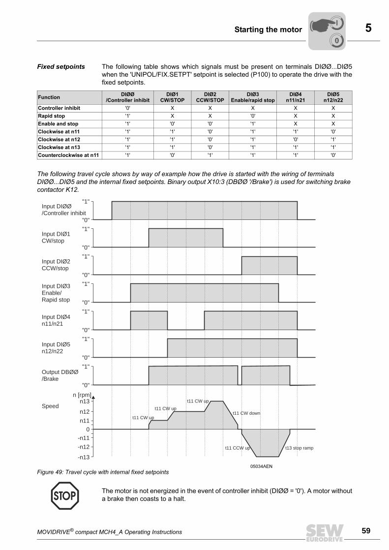
MOVIDRIVE® compact MCH4_A Operating Instructions 59
5Starting the motor
Fixed setpoints The following table shows which signals must be present on terminals DIØØ...DIØ5
when the 'UNIPOL/FIX.SETPT' setpoint is selected (P100) to operate the drive with the
fixed setpoints.
The following travel cycle shows by way of example how the drive is started with the wiring of terminals DIØØ...DIØ5 and the internal fixed setpoints. Binary output X10:3 (DBØØ '/Brake') is used for switching brake contactor K12.
FunctionDIØØ
/Controller inhibitDIØ1
CW/STOPDIØ2
CCW/STOPDIØ3
Enable/rapid stopDIØ4
n11/n21DIØ5
n12/n22
Controller inhibit '0' X X X X X
Rapid stop '1' X X '0' X X
Enable and stop '1' '0' '0' '1' X X
Clockwise at n11 '1' '1' '0' '1' '1' '0'
Clockwise at n12 '1' '1' '0' '1' '0' '1'
Clockwise at n13 '1' '1' '0' '1' '1' '1'
Counterclockwise at n11 '1' '0' '1' '1' '1' '0'
05034AEN
Figure 49: Travel cycle with internal fixed setpoints
The motor is not energized in the event of controller inhibit (DIØØ = '0'). A motor without
a brake then coasts to a halt.
"1"
"1"
"1"
"1"
"1"
"1"
"0"
"0"
"0"
"0"
"0"
"0"
n13
n12
-n12
-n13
0
"1"
"0"
n11
-n11
n [rpm]
Input DIØØ/Controller inhibit
Input DIØ1CW/stop
Input DIØ2CCW/stop
Input DIØ3Enable/Rapid stop
Input DIØ4n11/n21
Input DIØ5n12/n22
Speed
Output DBØØ/Brake
t11 CW up
t11 CW up
t11 CW upt11 CW down
t11 CCW up t13 stop ramp
00
I
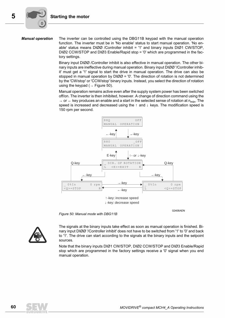
5
60 MOVIDRIVE® compact MCH4_A Operating Instructions
Starting the motor
Manual operation The inverter can be controlled using the DBG11B keypad with the manual operation
function. The inverter must be in 'No enable' status to start manual operation. 'No en-
able' status means DIØØ /Controller inhibit = '1' and binary inputs DIØ1 CW/STOP,
DIØ2 CCW/STOP and DIØ3 Enable/Rapid stop = '0' which are programmed in the fac-
tory settings.
Binary input DIØØ /Controller inhibit is also effective in manual operation. The other bi-
nary inputs are ineffective during manual operation. Binary input DIØØ '/Controller inhib-
it' must get a '1' signal to start the drive in manual operation. The drive can also be
stopped in manual operation by DIØØ = '0'. The direction of rotation is not determined
by the 'CW/stop' or 'CCW/stop' binary inputs. Instead, you select the direction of rotation
using the keypad (→ Figure 50).
Manual operation remains active even after the supply system power has been switched
off/on. The inverter is then inhibited, however. A change of direction command using the
→ or ← key produces an enable and a start in the selected sense of rotation at nmin. The
speed is increased and decreased using the ↑ and ↓ keys. The modification speed is
150 rpm per second.
02406AEN
Figure 50: Manual mode with DBG11B
↓ -key: decrease speed↑ -key: increase speed
Q-keyQ-key
E-key ↑ ↓- or -key
→-key
880 _OFF
MANUAL OPERATION
88 OFF
MANUAL OPERATION
0
_ DIR. OF ROTATION
L <E>=EXIT R
_ 0%In 0 rpm
<Q>=STOP R
_ 0%In 0 rpm
L <Q>=STOP
←-key
←-key
←-key
→-key
→-key
The signals at the binary inputs take effect as soon as manual operation is finished. Bi-
nary input DIØØ '/Controller inhibit' does not have to be switched from '1' to '0' and back
to '1'. The drive can start according to the signals at the binary inputs and the setpoint
sources.
Note that the binary inputs DIØ1 CW/STOP, DIØ2 CCW/STOP and DIØ3 Enable/Rapid
stop which are programmed in the factory settings receive a '0' signal when you end
manual operation.
00
I
MOVIDRIVE® compact MCH4_A Operating Instructions 61
5Startup for positioning tasks (MCH4_A)
5.6 Startup for positioning tasks (MCH4_A)
A Hiperface encoder connected to the MOVIDRIVE® compact MCH4_A provides abso-
lute position values and is a suitable device for positioning tasks. This statement holds
true for connection as motor encoder to X15 and as external encoder to X14.
A single reference travel is required to set up the absolute position.
Positioning with
the Hiperface
encoder as motor
encoder
The motor encoder can be used for positioning tasks for slip-free applications, i.e. a pos-
itive connection between drive and driven machine. Proceed as follows:
• Set parameter P941 "Source Actual Position = Motor Encoder (X15)."
• Set parameter P900 "Reference Offset." The following formula applies: machine zero
= reference point + reference offset.
• Set the reference travel parameters P901, P902, P903 and P904 according to your
application.
• Execute a reference travel. The reference travel can take place in two ways:
– Go to the manual operation menu in the MOVITOOLS operating software and
start the function "Reference travel."
– Writ an IPOS program for the reference travel and start this program.
Positioning with
the Hiperface
encocer as exter-
nal encoder
Use an external encoder for positioning in case of slip-prone applications, i.e. non-pos-
itive connection between drive and driven machine. Proceed as follows:
• Connect the Hiperface encoder to X14.
• Set the parameter P900 "Reference offset." The following formula applies: machine
zero = reference point + reference offset.
• Set the parameter P941 "Source Actual Position = Ext. Encoder (X14)."
• Set the reference travel parameters P901, P902, P903 and P904 according to your
application.
• Set parameter P945 "Synchronous encoder type (X14) = Hiperface."
• Execute a reference travel.
00
I
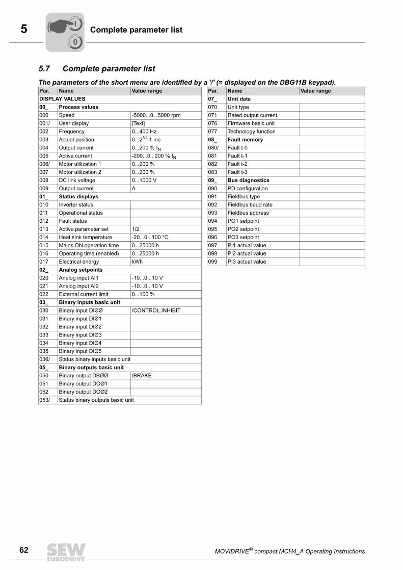
5
62 MOVIDRIVE® compact MCH4_A Operating Instructions
Complete parameter list
5.7 Complete parameter list
The parameters of the short menu are identified by a '/' (= displayed on the DBG11B keypad).Par. Name Value range Par. Name Value range
DISPLAY VALUES 07_ Unit data
00_ Process values 070 Unit type
000 Speed -5000...0...5000 rpm 071 Rated output current
001/ User display [Text] 076 Firmware basic unit
002 Frequency 0...400 Hz 077 Technology function
003 Actual position 0...231-1 inc 08_ Fault memory
004 Output current 0...200 % IN 080/ Fault t-0
005 Active current -200...0...200 % IN 081 Fault t-1
006/ Motor utilization 1 0...200 % 082 Fault t-2
007 Motor utilization 2 0...200 % 083 Fault t-3
008 DC link voltage 0...1000 V 09_ Bus diagnostics
009 Output current A 090 PD configuration
01_ Status displays 091 Fieldbus type
010 Inverter status 092 Fieldbus baud rate
011 Operational status 093 Fieldbus address
012 Fault status 094 PO1 setpoint
013 Active parameter set 1/2 095 PO2 setpoint
014 Heat sink temperature -20...0...100 °C 096 PO3 setpoint
015 Mains ON operation time 0...25000 h 097 PI1 actual value
016 Operating time (enabled) 0...25000 h 098 PI2 actual value
017 Electrical energy kWh 099 PI3 actual value
02_ Analog setpoints
020 Analog input AI1 -10...0...10 V
021 Analog input AI2 -10...0...10 V
022 External current limit 0...100 %
03_ Binary inputs basic unit
030 Binary input DIØØ /CONTROL.INHIBIT
031 Binary input DIØ1
032 Binary input DIØ2
033 Binary input DIØ3
034 Binary input DIØ4
035 Binary input DIØ5
036/ Status binary inputs basic unit
05_ Binary outputs basic unit
050 Binary output DBØØ /BRAKE
051 Binary output DOØ1
052 Binary output DOØ2
053/ Status binary outputs basic unit
00
I
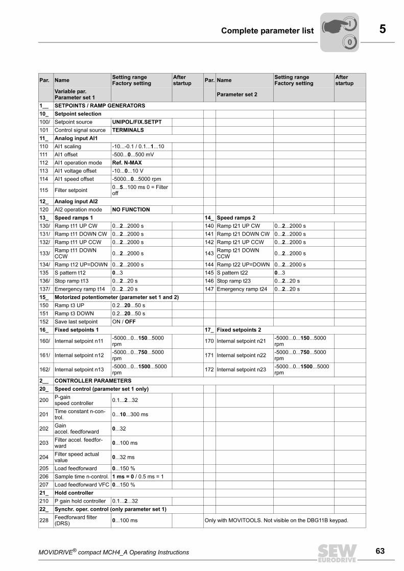
MOVIDRIVE® compact MCH4_A Operating Instructions 63
5Complete parameter list
Par. NameSetting rangeFactory setting
Afterstartup
Par. NameSetting rangeFactory setting
Afterstartup
Variable par.Parameter set 1
Parameter set 2
1__ SETPOINTS / RAMP GENERATORS
10_ Setpoint selection
100/ Setpoint source UNIPOL/FIX.SETPT
101 Control signal source TERMINALS
11_ Analog input AI1
110 AI1 scaling -10...-0.1 / 0.1...1...10
111 AI1 offset -500...0...500 mV
112 AI1 operation mode Ref. N-MAX
113 AI1 voltage offset -10...0...10 V
114 AI1 speed offset -5000...0...5000 rpm
115 Filter setpoint0...5...100 ms 0 = Filter off
12_ Analog input AI2
120 AI2 operation mode NO FUNCTION
13_ Speed ramps 1 14_ Speed ramps 2
130/ Ramp t11 UP CW 0...2...2000 s 140 Ramp t21 UP CW 0...2...2000 s
131/ Ramp t11 DOWN CW 0...2...2000 s 141 Ramp t21 DOWN CW 0...2...2000 s
132/ Ramp t11 UP CCW 0...2...2000 s 142 Ramp t21 UP CCW 0...2...2000 s
133/Ramp t11 DOWN CCW
0...2...2000 s 143Ramp t21 DOWN CCW
0...2...2000 s
134/ Ramp t12 UP=DOWN 0...2...2000 s 144 Ramp t22 UP=DOWN 0...2...2000 s
135 S pattern t12 0...3 145 S pattern t22 0...3
136/ Stop ramp t13 0...2...20 s 146 Stop ramp t23 0...2...20 s
137/ Emergency ramp t14 0...2...20 s 147 Emergency ramp t24 0...2...20 s
15_ Motorized potentiometer (parameter set 1 and 2)
150 Ramp t3 UP 0.2...20...50 s
151 Ramp t3 DOWN 0.2...20...50 s
152 Save last setpoint ON / OFF
16_ Fixed setpoints 1 17_ Fixed setpoints 2
160/ Internal setpoint n11-5000...0...150...5000 rpm
170 Internal setpoint n21-5000...0...150...5000 rpm
161/ Internal setpoint n12-5000...0...750...5000 rpm
171 Internal setpoint n22-5000...0...750...5000 rpm
162/ Internal setpoint n13-5000...0...1500...5000 rpm
172 Internal setpoint n23-5000...0...1500...5000 rpm
2__ CONTROLLER PARAMETERS
20_ Speed control (parameter set 1 only)
200P-gainspeed controller
0.1...2...32
201Time constant n-con-trol.
0...10...300 ms
202Gainaccel. feedforward
0...32
203Filter accel. feedfor-ward
0...100 ms
204Filter speed actual value
0...32 ms
205 Load feedforward 0...150 %
206 Sample time n-control. 1 ms = 0 / 0.5 ms = 1
207 Load feedforward VFC 0...150 %
21_ Hold controller
210 P gain hold controller 0.1...2...32
22_ Synchr. oper. control (only parameter set 1)
228Feedforward filter (DRS)
0...100 ms Only with MOVITOOLS. Not visible on the DBG11B keypad.
00
I
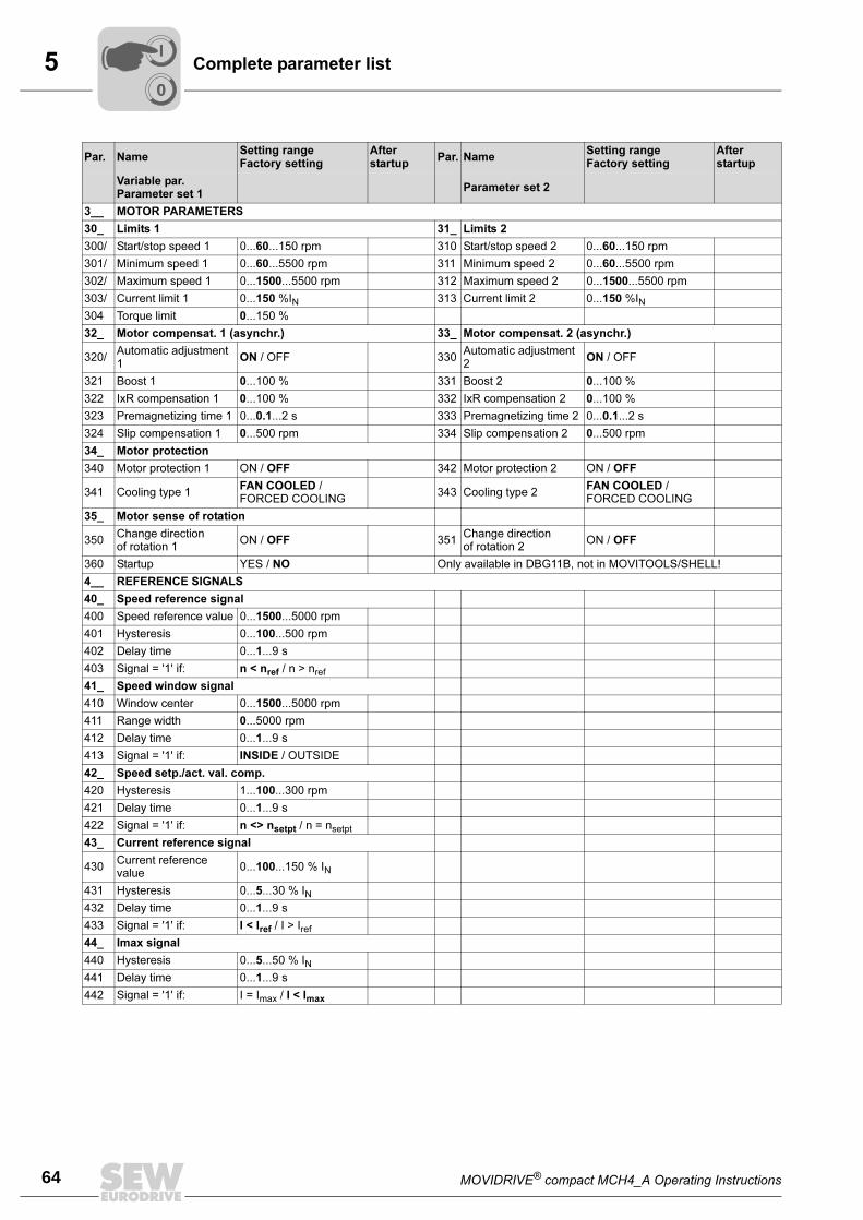
5
64 MOVIDRIVE® compact MCH4_A Operating Instructions
Complete parameter list
3__ MOTOR PARAMETERS
30_ Limits 1 31_ Limits 2
300/ Start/stop speed 1 0...60...150 rpm 310 Start/stop speed 2 0...60...150 rpm
301/ Minimum speed 1 0...60...5500 rpm 311 Minimum speed 2 0...60...5500 rpm
302/ Maximum speed 1 0...1500...5500 rpm 312 Maximum speed 2 0...1500...5500 rpm
303/ Current limit 1 0...150 %IN 313 Current limit 2 0...150 %IN
304 Torque limit 0...150 %
32_ Motor compensat. 1 (asynchr.) 33_ Motor compensat. 2 (asynchr.)
320/Automatic adjustment 1
ON / OFF 330Automatic adjustment 2
ON / OFF
321 Boost 1 0...100 % 331 Boost 2 0...100 %
322 IxR compensation 1 0...100 % 332 IxR compensation 2 0...100 %
323 Premagnetizing time 1 0...0.1...2 s 333 Premagnetizing time 2 0...0.1...2 s
324 Slip compensation 1 0...500 rpm 334 Slip compensation 2 0...500 rpm
34_ Motor protection
340 Motor protection 1 ON / OFF 342 Motor protection 2 ON / OFF
341 Cooling type 1FAN COOLED / FORCED COOLING
343 Cooling type 2FAN COOLED / FORCED COOLING
35_ Motor sense of rotation
350Change direction of rotation 1
ON / OFF 351Change direction of rotation 2
ON / OFF
360 Startup YES / NO Only available in DBG11B, not in MOVITOOLS/SHELL!
4__ REFERENCE SIGNALS
40_ Speed reference signal
400 Speed reference value 0...1500...5000 rpm
401 Hysteresis 0...100...500 rpm
402 Delay time 0...1...9 s
403 Signal = '1' if: n < nref / n > nref
41_ Speed window signal
410 Window center 0...1500...5000 rpm
411 Range width 0...5000 rpm
412 Delay time 0...1...9 s
413 Signal = '1' if: INSIDE / OUTSIDE
42_ Speed setp./act. val. comp.
420 Hysteresis 1...100...300 rpm
421 Delay time 0...1...9 s
422 Signal = '1' if: n <> nsetpt / n = nsetpt
43_ Current reference signal
430Current reference value
0...100...150 % IN
431 Hysteresis 0...5...30 % IN
432 Delay time 0...1...9 s
433 Signal = '1' if: I < Iref / I > Iref
44_ Imax signal
440 Hysteresis 0...5...50 % IN
441 Delay time 0...1...9 s
442 Signal = '1' if: I = Imax / I < Imax
Par. NameSetting rangeFactory setting
Afterstartup
Par. NameSetting rangeFactory setting
Afterstartup
Variable par.Parameter set 1
Parameter set 2
00
I
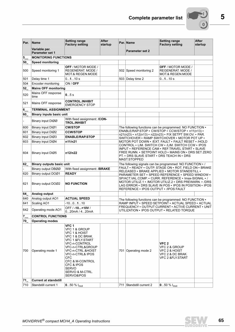
MOVIDRIVE® compact MCH4_A Operating Instructions 65
5Complete parameter list
5__ MONITORING FUNCTIONS
50_ Speed monitoring
500 Speed monitoring 1OFF / MOTOR MODE / REGENERAT. MODE / MOT.& REGEN.MODE
502 Speed monitoring 2OFF / MOTOR MODE / REGENERAT. MODE / MOT.& REGEN.MODE
501 Delay time 1 0...1...10 s 503 Delay time 2 0...1...10 s
504 Encoder monitoring ON / OFF
52_ Mains OFF monitoring
520Mains OFF response time
0...5 s
521 Mains OFF responseCONTROL.INHIBIT EMERGENCY STOP
6__ TERMINAL ASSIGNMENT
60_ Binary inputs basic unit
- Binary input DIØØWith fixed assignment: /CON-TROL.INHIBIT
600 Binary input DIØ1 CW/STOP The following functions can be programmed: NO FUNCTION • ENABLE/RAP.STOP • CW/STOP • CCW/STOP • n11(n13) • n21(n23) • n12(n13) • n22(n23) • FIX SETPT SW.OV. • PAR. SWITCHOVER • RAMP SWITCHOVER • MOTOR POT UP • MOTOR POT DOWN • /EXT. FAULT • FAULT RESET • /HOLD CONTROL • LIM. SWITCH CW • /LIM. SWITCH CCW • IPOS INPUT • REFERENCE CAM • REF.TRAVEL START • SLAVE FREE RUNN. • SETPOINT HOLD • MAINS ON • DRS SET ZERO PT. • DRS SLAVE START • DRS TEACH IN • DRS MAST.STOPPED
601 Binary input DIØ2 CCW/STOP
602 Binary input DIØ3 ENABLE/RAP.STOP
603 Binary input DIØ4 n11/n21
604 Binary input DIØ5 n12/n22
62_ Binary outputs basic unit The following signals can be programmed: NO FUNCTION • /FAULT • READY • OUTP. STAGE ON • ROT. FIELD ON • BRAKE RELEASED • BRAKE APPLIED • MOTOR STANDSTILL • PARAMETER SET • SPEED REFERENCE • SPEED WINDOW • SP/ACT.VAL.COMP. • CURR. REFERENCE • Imax-SIGNAL • /MOTOR UTILIZ.1 • /MOTOR UTILIZ.2 • DRS PREWARN. • /DRS LAG ERROR • DRS SLAVE IN POS • IPOS IN POSITION • IPOS REFERENCE • IPOS OUTPUT • /IPOS FAULT
- Binary output DBØØ With fixed assignment: /BRAKE
620 Binary output DOØ1 READY
621 Binary output DOØ2 NO FUNCTION
64_ Analog output
640 Analog output AO1 ACTUAL SPEED The following functions can be programmed: NO FUNCTION • RAMP INPUT • SPEED SETPOINT • ACTUAL SPEED • ACTUAL FREQUENCY • OUTPUT CURRENT • ACTIVE CURRENT • UNIT UTILIZATION • IPOS OUTPUT • RELATED TORQUE
641 Scaling AO1 -10...0...1...10
642 Operating mode AO1OFF / -10...+10V / 0...20mA / 4...20mA
7__ CONTROL FUNCTIONS
70_ Operating modes
700 Operating mode 1
VFC 1 VFC 1 & GROUPVFC 1 & HOISTVFC 1 & DC BRAK.VFC 1 &FLY.STARTVFC-n-CONTROLVFC-n-CTRL&GROUP VFC-n-CTRL.&HOIST VFC-n-CTRL& IPOSCFCCFC & M-CONTROLCFC & IPOSSERVOSERVO & M-CTRL. SERVO&IPOS
701 Operating mode 2
VFC 2 VFC 2 & GROUPVFC 2 & HOISTVFC 2 & DC BRAK.VFC 2 &FLY.START
71_ Current at standstill
710 Standstill current 1 0...50 % Imot 711 Standstill current 2 0...50 % Imot
Par. NameSetting rangeFactory setting
Afterstartup
Par. NameSetting rangeFactory setting
Afterstartup
Variable par.Parameter set 1
Parameter set 2
00
I
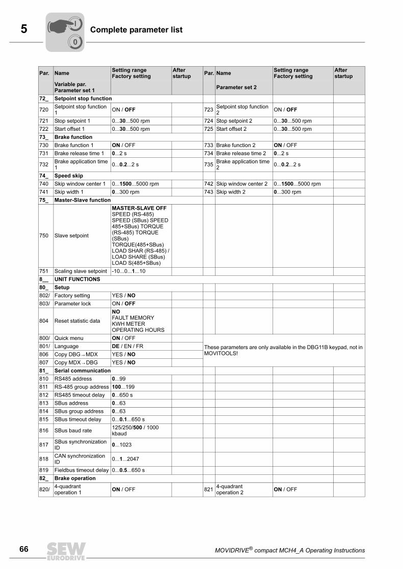
5
66 MOVIDRIVE® compact MCH4_A Operating Instructions
Complete parameter list
72_ Setpoint stop function
720Setpoint stop function 1
ON / OFF 723Setpoint stop function 2
ON / OFF
721 Stop setpoint 1 0...30...500 rpm 724 Stop setpoint 2 0...30...500 rpm
722 Start offset 1 0...30...500 rpm 725 Start offset 2 0...30...500 rpm
73_ Brake function
730 Brake function 1 ON / OFF 733 Brake function 2 ON / OFF
731 Brake release time 1 0...2 s 734 Brake release time 2 0...2 s
732Brake application time 1
0...0.2...2 s 735Brake application time 2
0...0.2...2 s
74_ Speed skip
740 Skip window center 1 0...1500...5000 rpm 742 Skip window center 2 0...1500...5000 rpm
741 Skip width 1 0...300 rpm 743 Skip width 2 0...300 rpm
75_ Master-Slave function
750 Slave setpoint
MASTER-SLAVE OFF SPEED (RS-485) SPEED (SBus) SPEED 485+SBus) TORQUE (RS-485) TORQUE (SBus) TORQUE(485+SBus) LOAD SHAR (RS-485) / LOAD SHARE (SBus) LOAD S(485+SBus)
751 Scaling slave setpoint -10...0...1...10
8__ UNIT FUNCTIONS
80_ Setup
802/ Factory setting YES / NO
803/ Parameter lock ON / OFF
804 Reset statistic data
NO FAULT MEMORYKWH METEROPERATING HOURS
800/ Quick menu ON / OFF
These parameters are only available in the DBG11B keypad, not in MOVITOOLS!
801/ Language DE / EN / FR
806 Copy DBG→MDX YES / NO
807 Copy MDX→DBG YES / NO
81_ Serial communication
810 RS485 address 0...99
811 RS-485 group address 100...199
812 RS485 timeout delay 0...650 s
813 SBus address 0...63
814 SBus group address 0...63
815 SBus timeout delay 0...0.1...650 s
816 SBus baud rate125/250/500 / 1000 kbaud
817SBus synchronization ID
0...1023
818CAN synchronization ID
0...1...2047
819 Fieldbus timeout delay 0...0.5...650 s
82_ Brake operation
820/4-quadrantoperation 1
ON / OFF 8214-quadrantoperation 2
ON / OFF
Par. NameSetting rangeFactory setting
Afterstartup
Par. NameSetting rangeFactory setting
Afterstartup
Variable par.Parameter set 1
Parameter set 2
00
I
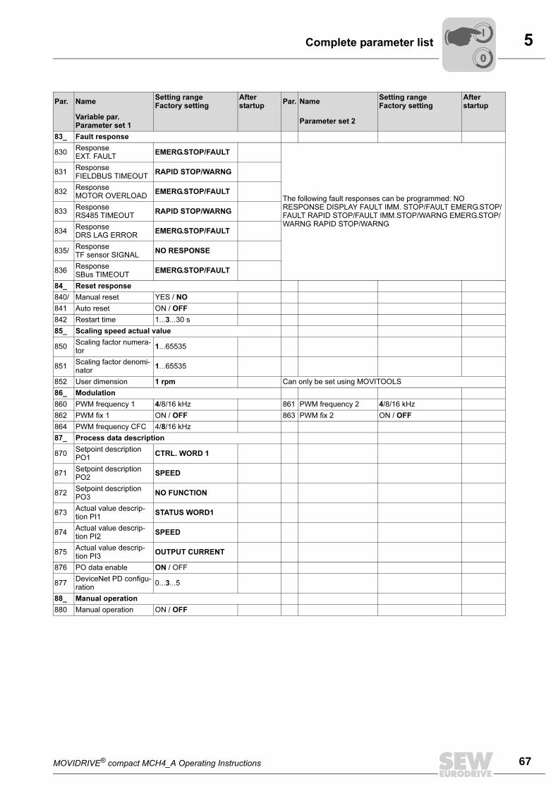
MOVIDRIVE® compact MCH4_A Operating Instructions 67
5Complete parameter list
83_ Fault response
830ResponseEXT. FAULT
EMERG.STOP/FAULT
The following fault responses can be programmed: NO RESPONSE DISPLAY FAULT IMM. STOP/FAULT EMERG.STOP/FAULT RAPID STOP/FAULT IMM.STOP/WARNG EMERG.STOP/WARNG RAPID STOP/WARNG
831ResponseFIELDBUS TIMEOUT
RAPID STOP/WARNG
832ResponseMOTOR OVERLOAD
EMERG.STOP/FAULT
833ResponseRS485 TIMEOUT
RAPID STOP/WARNG
834ResponseDRS LAG ERROR
EMERG.STOP/FAULT
835/ResponseTF sensor SIGNAL
NO RESPONSE
836ResponseSBus TIMEOUT
EMERG.STOP/FAULT
84_ Reset response
840/ Manual reset YES / NO
841 Auto reset ON / OFF
842 Restart time 1...3...30 s
85_ Scaling speed actual value
850Scaling factor numera-tor
1...65535
851Scaling factor denomi-nator
1...65535
852 User dimension 1 rpm Can only be set using MOVITOOLS
86_ Modulation
860 PWM frequency 1 4/8/16 kHz 861 PWM frequency 2 4/8/16 kHz
862 PWM fix 1 ON / OFF 863 PWM fix 2 ON / OFF
864 PWM frequency CFC 4/8/16 kHz
87_ Process data description
870Setpoint description PO1
CTRL. WORD 1
871Setpoint description PO2
SPEED
872Setpoint description PO3
NO FUNCTION
873Actual value descrip-tion PI1
STATUS WORD1
874Actual value descrip-tion PI2
SPEED
875Actual value descrip-tion PI3
OUTPUT CURRENT
876 PO data enable ON / OFF
877DeviceNet PD configu-ration
0...3...5
88_ Manual operation
880 Manual operation ON / OFF
Par. NameSetting rangeFactory setting
Afterstartup
Par. NameSetting rangeFactory setting
Afterstartup
Variable par.Parameter set 1
Parameter set 2
00
I
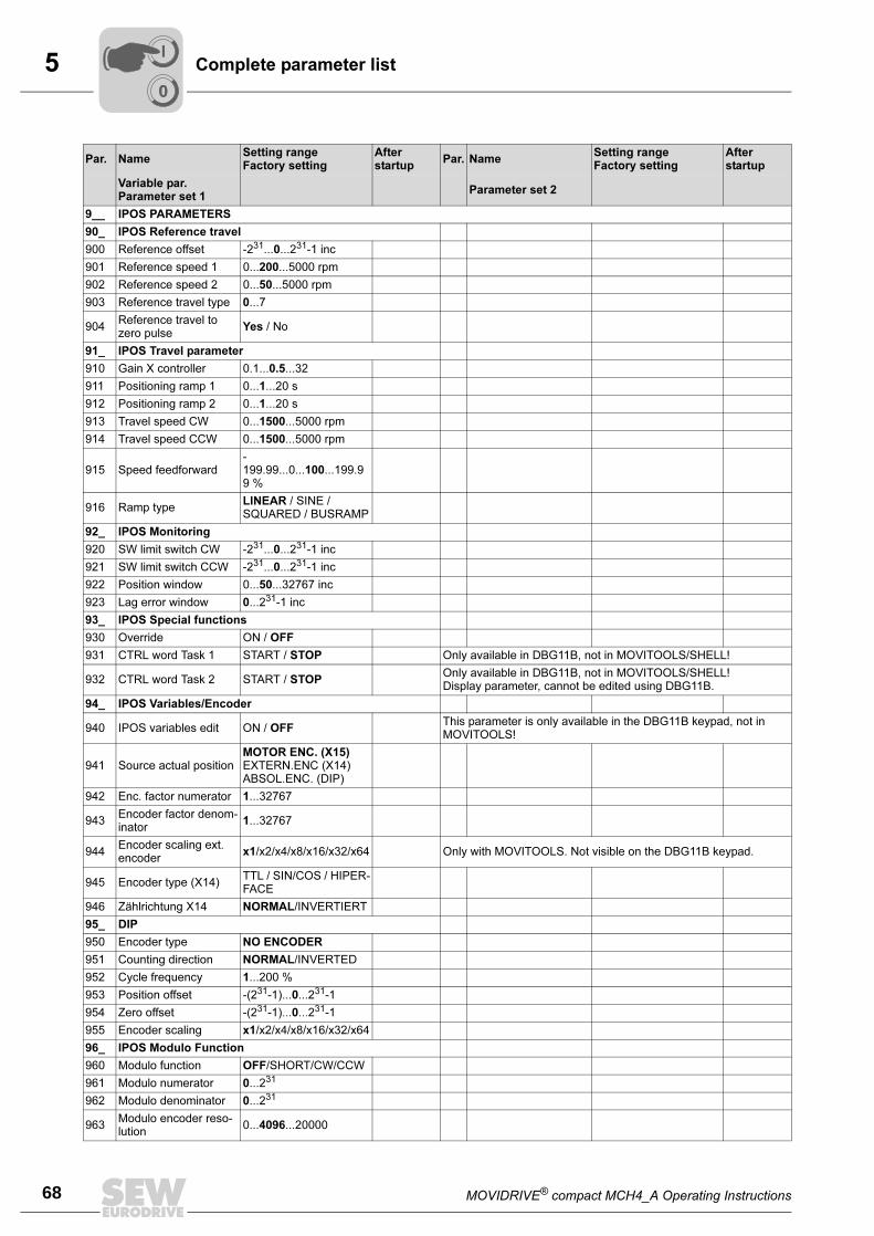
5
68 MOVIDRIVE® compact MCH4_A Operating Instructions
Complete parameter list
9__ IPOS PARAMETERS
90_ IPOS Reference travel
900 Reference offset -231...0...231-1 inc
901 Reference speed 1 0...200...5000 rpm
902 Reference speed 2 0...50...5000 rpm
903 Reference travel type 0...7
904Reference travel to zero pulse
Yes / No
91_ IPOS Travel parameter
910 Gain X controller 0.1...0.5...32
911 Positioning ramp 1 0...1...20 s
912 Positioning ramp 2 0...1...20 s
913 Travel speed CW 0...1500...5000 rpm
914 Travel speed CCW 0...1500...5000 rpm
915 Speed feedforward-199.99...0...100...199.99 %
916 Ramp typeLINEAR / SINE / SQUARED / BUSRAMP
92_ IPOS Monitoring
920 SW limit switch CW -231...0...231-1 inc
921 SW limit switch CCW -231...0...231-1 inc
922 Position window 0...50...32767 inc
923 Lag error window 0...231-1 inc
93_ IPOS Special functions
930 Override ON / OFF
931 CTRL word Task 1 START / STOP Only available in DBG11B, not in MOVITOOLS/SHELL!
932 CTRL word Task 2 START / STOPOnly available in DBG11B, not in MOVITOOLS/SHELL!Display parameter, cannot be edited using DBG11B.
94_ IPOS Variables/Encoder
940 IPOS variables edit ON / OFFThis parameter is only available in the DBG11B keypad, not in MOVITOOLS!
941 Source actual positionMOTOR ENC. (X15) EXTERN.ENC (X14) ABSOL.ENC. (DIP)
942 Enc. factor numerator 1...32767
943Encoder factor denom-inator
1...32767
944Encoder scaling ext. encoder
x1/x2/x4/x8/x16/x32/x64 Only with MOVITOOLS. Not visible on the DBG11B keypad.
945 Encoder type (X14)TTL / SIN/COS / HIPER-FACE
946 Zählrichtung X14 NORMAL/INVERTIERT
95_ DIP
950 Encoder type NO ENCODER
951 Counting direction NORMAL/INVERTED
952 Cycle frequency 1...200 %
953 Position offset -(231-1)...0...231-1
954 Zero offset -(231-1)...0...231-1
955 Encoder scaling x1/x2/x4/x8/x16/x32/x64
96_ IPOS Modulo Function
960 Modulo function OFF/SHORT/CW/CCW
961 Modulo numerator 0...231
962 Modulo denominator 0...231
963Modulo encoder reso-lution
0...4096...20000
Par. NameSetting rangeFactory setting
Afterstartup
Par. NameSetting rangeFactory setting
Afterstartup
Variable par.Parameter set 1
Parameter set 2
00
I
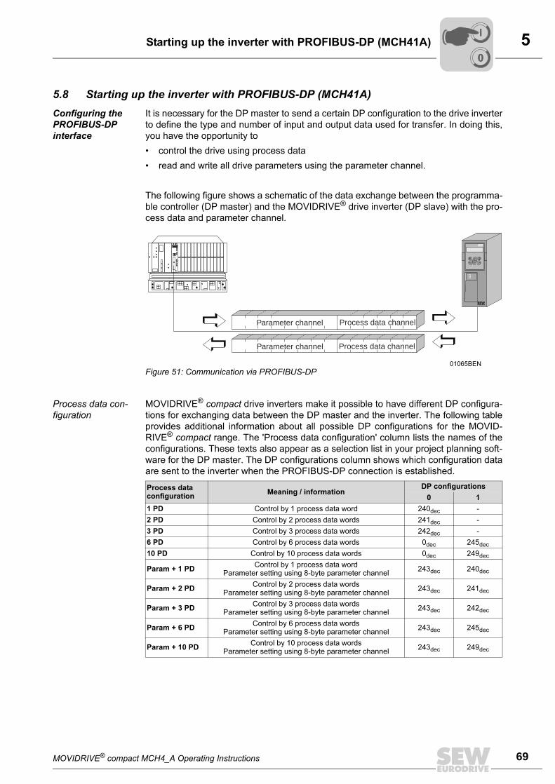
MOVIDRIVE® compact MCH4_A Operating Instructions 69
5Starting up the inverter with PROFIBUS-DP (MCH41A)
5.8 Starting up the inverter with PROFIBUS-DP (MCH41A)
Configuring the
PROFIBUS-DP
interface
It is necessary for the DP master to send a certain DP configuration to the drive inverter
to define the type and number of input and output data used for transfer. In doing this,
you have the opportunity to
• control the drive using process data
• read and write all drive parameters using the parameter channel.
The following figure shows a schematic of the data exchange between the programma-
ble controller (DP master) and the MOVIDRIVE® drive inverter (DP slave) with the pro-
cess data and parameter channel.
Process data con-
figuration
MOVIDRIVE® compact drive inverters make it possible to have different DP configura-
tions for exchanging data between the DP master and the inverter. The following table
provides additional information about all possible DP configurations for the MOVID-
RIVE® compact range. The 'Process data configuration' column lists the names of the
configurations. These texts also appear as a selection list in your project planning soft-
ware for the DP master. The DP configurations column shows which configuration data
are sent to the inverter when the PROFIBUS-DP connection is established.
01065BEN
Figure 51: Communication via PROFIBUS-DP
E Q
Parameter channel
Parameter channel
Process data channel
Process data channel
Process data configuration
Meaning / informationDP configurations
0 1
1 PD Control by 1 process data word 240dec -
2 PD Control by 2 process data words 241dec -
3 PD Control by 3 process data words 242dec -
6 PD Control by 6 process data words 0dec 245dec
10 PD Control by 10 process data words 0dec 249dec
Param + 1 PDControl by 1 process data word
Parameter setting using 8-byte parameter channel243dec 240dec
Param + 2 PDControl by 2 process data words
Parameter setting using 8-byte parameter channel243dec 241dec
Param + 3 PDControl by 3 process data words
Parameter setting using 8-byte parameter channel243dec 242dec
Param + 6 PDControl by 6 process data words
Parameter setting using 8-byte parameter channel243dec 245dec
Param + 10 PDControl by 10 process data words
Parameter setting using 8-byte parameter channel243dec 249dec
00
I
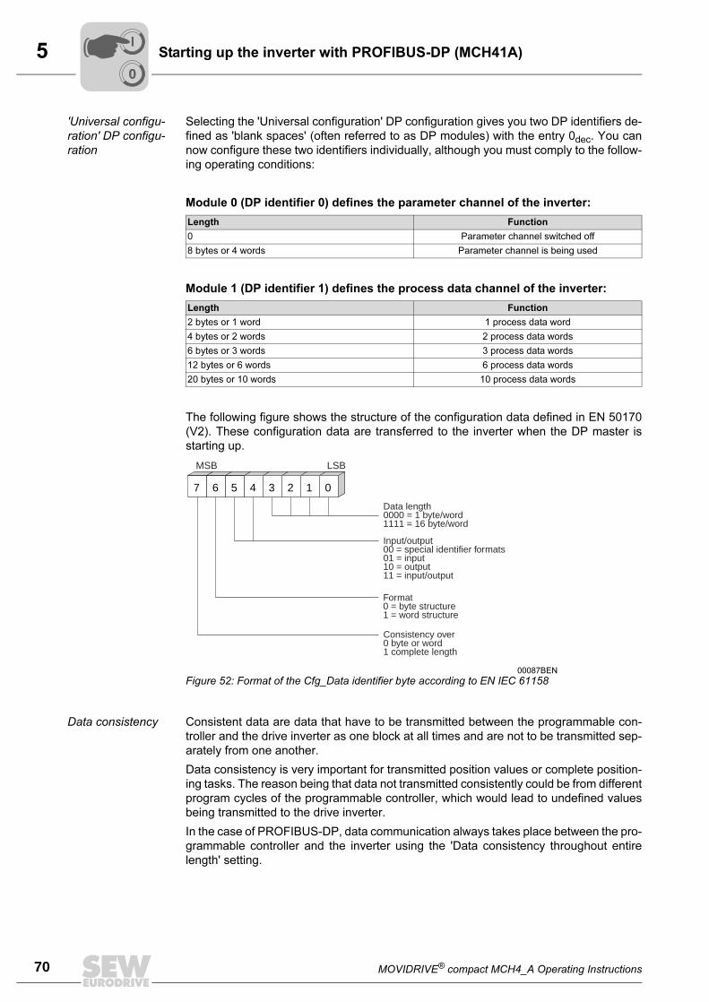
5
70 MOVIDRIVE® compact MCH4_A Operating Instructions
Starting up the inverter with PROFIBUS-DP (MCH41A)
'Universal configu-
ration' DP configu-
ration
Selecting the 'Universal configuration' DP configuration gives you two DP identifiers de-
fined as 'blank spaces' (often referred to as DP modules) with the entry 0dec. You can
now configure these two identifiers individually, although you must comply to the follow-
ing operating conditions:
Module 0 (DP identifier 0) defines the parameter channel of the inverter:
Module 1 (DP identifier 1) defines the process data channel of the inverter:
The following figure shows the structure of the configuration data defined in EN 50170
(V2). These configuration data are transferred to the inverter when the DP master is
starting up.
Data consistency Consistent data are data that have to be transmitted between the programmable con-
troller and the drive inverter as one block at all times and are not to be transmitted sep-
arately from one another.
Data consistency is very important for transmitted position values or complete position-
ing tasks. The reason being that data not transmitted consistently could be from different
program cycles of the programmable controller, which would lead to undefined values
being transmitted to the drive inverter.
In the case of PROFIBUS-DP, data communication always takes place between the pro-
grammable controller and the inverter using the 'Data consistency throughout entire
length' setting.
Length Function
0 Parameter channel switched off
8 bytes or 4 words Parameter channel is being used
Length Function
2 bytes or 1 word 1 process data word
4 bytes or 2 words 2 process data words
6 bytes or 3 words 3 process data words
12 bytes or 6 words 6 process data words
20 bytes or 10 words 10 process data words
00087BEN
Figure 52: Format of the Cfg_Data identifier byte according to EN IEC 61158
7 6 5 4 3 2 1 0
MSB LSB
Data length0000 = 1 byte/word1111 = 16 byte/word
Input/output00 = special identifier formats01 = input10 = output11 = input/output
Format0 = byte structure1 = word structure
Consistency over0 byte or word1 complete length
00
I
MOVIDRIVE® compact MCH4_A Operating Instructions 71
5Starting up the inverter with PROFIBUS-DP (MCH41A)
External diagnos-
tics
For MOVIDRIVE® compact, it is possible to activate automatic generation of external di-
agnostic alarms via PROFIBUS-DP during the project planning in the DP master. If this
function has been activated, MOVIDRIVE® compact sends an external diagnostic signal
to the DP master every time a malfunction occurs. It is then necessary to program cor-
responding algorithms in the program of the DP master system to evaluate the diagnos-
tic information. These algorithms can sometimes be quite complex.
Recommendation It is basically not necessary to activate the external diagnostic function because MOV-
IDRIVE® compact transmits the current drive status in status word 1 during every
PROFIBUS-DP cycle.
Note regarding
Simatic S7 master
systems
Diagnostic alarms may be triggered by the PROFIBUS-DP system in the DP master at
any time even when external diagnostic signal generation is inactive. This means the
corresponding operation blocks (e.g. OB84 for S7-400 or OB82 for S7-300) should al-
ways be created in the controller.
For more information, please refer to the Readme file included with the GSD file.
Identity number Each DP master and DP slave must have its individual identity number which is as-
signed by the PROFIBUS user organization. This number uniquely identifies the con-
nected unit. When the PROFIBUS-DP master starts up, it compares the identity num-
bers of the connected DP slaves with the identity numbers the user has entered in the
project planning. User data transfer is not activated until the DP master has made sure
that the connected station addresses and unit types (identity numbers) correspond to
the project planning data. As a result, this process provides a high degree of protection
against project planning mistakes.
The identity number is defined as an unsigned 16-bit number. The PROFIBUS user or-
ganization has defined the following identity numbers for the MOVIDRIVE® compact
drive inverter unit series.
• MOVIDRIVE® compact MCH41A → 6003hex (24579dec)
00
I
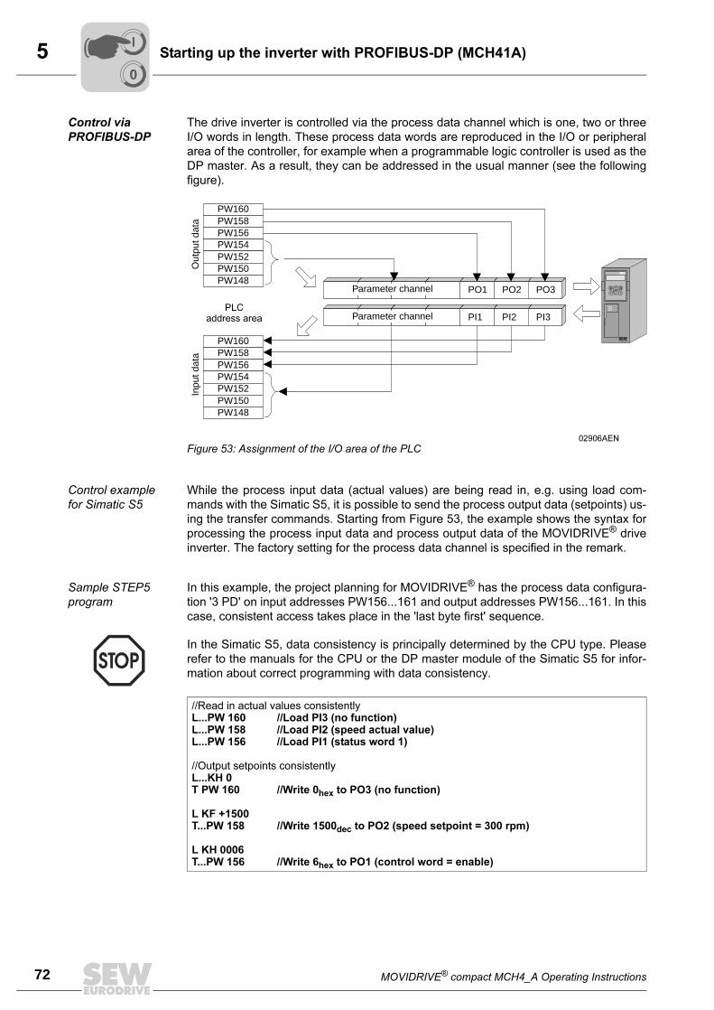
5
72 MOVIDRIVE® compact MCH4_A Operating Instructions
Starting up the inverter with PROFIBUS-DP (MCH41A)
Control via
PROFIBUS-DP
The drive inverter is controlled via the process data channel which is one, two or three
I/O words in length. These process data words are reproduced in the I/O or peripheral
area of the controller, for example when a programmable logic controller is used as the
DP master. As a result, they can be addressed in the usual manner (see the following
figure).
Control example
for Simatic S5
While the process input data (actual values) are being read in, e.g. using load com-
mands with the Simatic S5, it is possible to send the process output data (setpoints) us-
ing the transfer commands. Starting from Figure 53, the example shows the syntax for
processing the process input data and process output data of the MOVIDRIVE® drive
inverter. The factory setting for the process data channel is specified in the remark.
Sample STEP5
program
In this example, the project planning for MOVIDRIVE® has the process data configura-
tion '3 PD' on input addresses PW156...161 and output addresses PW156...161. In this
case, consistent access takes place in the 'last byte first' sequence.
02906AEN
Figure 53: Assignment of the I/O area of the PLC
PW160PW158PW156PW154PW152PW150PW148
PO1 PO2 PO3
PI1 PI2 PI3
PW160PW158PW156PW154PW152PW150PW148
E QParameter channel
Parameter channelPLC
address area
Out
put d
ata
Inpu
t dat
a
In the Simatic S5, data consistency is principally determined by the CPU type. Please
refer to the manuals for the CPU or the DP master module of the Simatic S5 for infor-
mation about correct programming with data consistency.
//Read in actual values consistentlyL...PW 160 //Load PI3 (no function)L...PW 158 //Load PI2 (speed actual value)L...PW 156 //Load PI1 (status word 1)
//Output setpoints consistentlyL...KH 0T PW 160 //Write 0hex to PO3 (no function)
L KF +1500T...PW 158 //Write 1500dec to PO2 (speed setpoint = 300 rpm)
L KH 0006T...PW 156 //Write 6hex to PO1 (control word = enable)
00
I
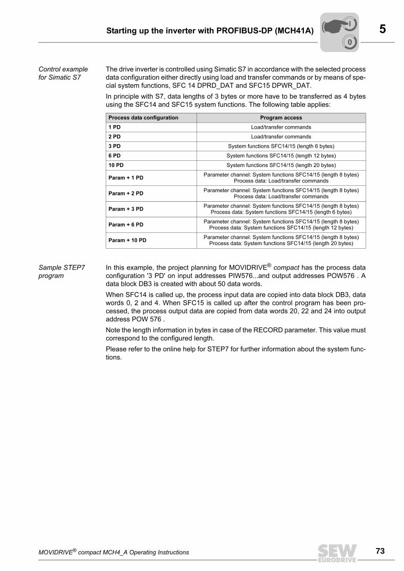
MOVIDRIVE® compact MCH4_A Operating Instructions 73
5Starting up the inverter with PROFIBUS-DP (MCH41A)
Control example
for Simatic S7
The drive inverter is controlled using Simatic S7 in accordance with the selected process
data configuration either directly using load and transfer commands or by means of spe-
cial system functions, SFC 14 DPRD_DAT and SFC15 DPWR_DAT.
In principle with S7, data lengths of 3 bytes or more have to be transferred as 4 bytes
using the SFC14 and SFC15 system functions. The following table applies:
Sample STEP7
program
In this example, the project planning for MOVIDRIVE® compact has the process data
configuration '3 PD' on input addresses PIW576...and output addresses POW576 . A
data block DB3 is created with about 50 data words.
When SFC14 is called up, the process input data are copied into data block DB3, data
words 0, 2 and 4. When SFC15 is called up after the control program has been pro-
cessed, the process output data are copied from data words 20, 22 and 24 into output
address POW 576 .
Note the length information in bytes in case of the RECORD parameter. This value must
correspond to the configured length.
Please refer to the online help for STEP7 for further information about the system func-
tions.
Process data configuration Program access
1 PD Load/transfer commands
2 PD Load/transfer commands
3 PD System functions SFC14/15 (length 6 bytes)
6 PD System functions SFC14/15 (length 12 bytes)
10 PD System functions SFC14/15 (length 20 bytes)
Param + 1 PDParameter channel: System functions SFC14/15 (length 8 bytes)
Process data: Load/transfer commands
Param + 2 PDParameter channel: System functions SFC14/15 (length 8 bytes)
Process data: Load/transfer commands
Param + 3 PDParameter channel: System functions SFC14/15 (length 8 bytes)
Process data: System functions SFC14/15 (length 6 bytes)
Param + 6 PDParameter channel: System functions SFC14/15 (length 8 bytes)
Process data: System functions SFC14/15 (length 12 bytes)
Param + 10 PDParameter channel: System functions SFC14/15 (length 8 bytes)
Process data: System functions SFC14/15 (length 20 bytes)
00
I
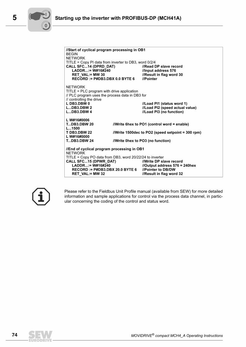
5
74 MOVIDRIVE® compact MCH4_A Operating Instructions
Starting up the inverter with PROFIBUS-DP (MCH41A)
//Start of cyclical program processing in OB1BEGINNETWORKTITLE = Copy PI data from inverter to DB3, word 0/2/4CALL SFC...14 (DPRD_DAT) //Read DP slave record
LADDR...:= W#16#240 //Input address 576RET_VAL:= MW 30 //Result in flag word 30RECORD := P#DB3.DBX 0.0 BYTE 6 //Pointer
NETWORKTITLE = PLC program with drive application// PLC program uses the process data in DB3 for// controlling the driveL DB3.DBW 0 //Load PI1 (status word 1)L...DB3.DBW 2 //Load PI2 (speed actual value)L...DB3.DBW 4 //Load PI3 (no function)
L W#16#0006T...DB3.DBW 20 //Write 6hex to PO1 (control word = enable)L...1500T DB3.DBW 22 //Write 1500dec to PO2 (speed setpoint = 300 rpm)L W#16#0000T...DB3.DBW 24 //Write 0hex to PO3 (no function)
//End of cyclical program processing in OB1NETWORKTITLE = Copy PO data from DB3, word 20/22/24 to inverterCALL SFC...15 (DPWR_DAT) //Write DP slave record
LADDR...:= W#16#240 //Output address 576 = 240hexRECORD := P#DB3.DBX 20.0 BYTE 6 //Pointer to DB/DWRET_VAL:= MW 32 //Result in flag word 32
Please refer to the Fieldbus Unit Profile manual (available from SEW) for more detailed
information and sample applications for control via the process data channel, in partic-
ular concerning the coding of the control and status word.
00
I
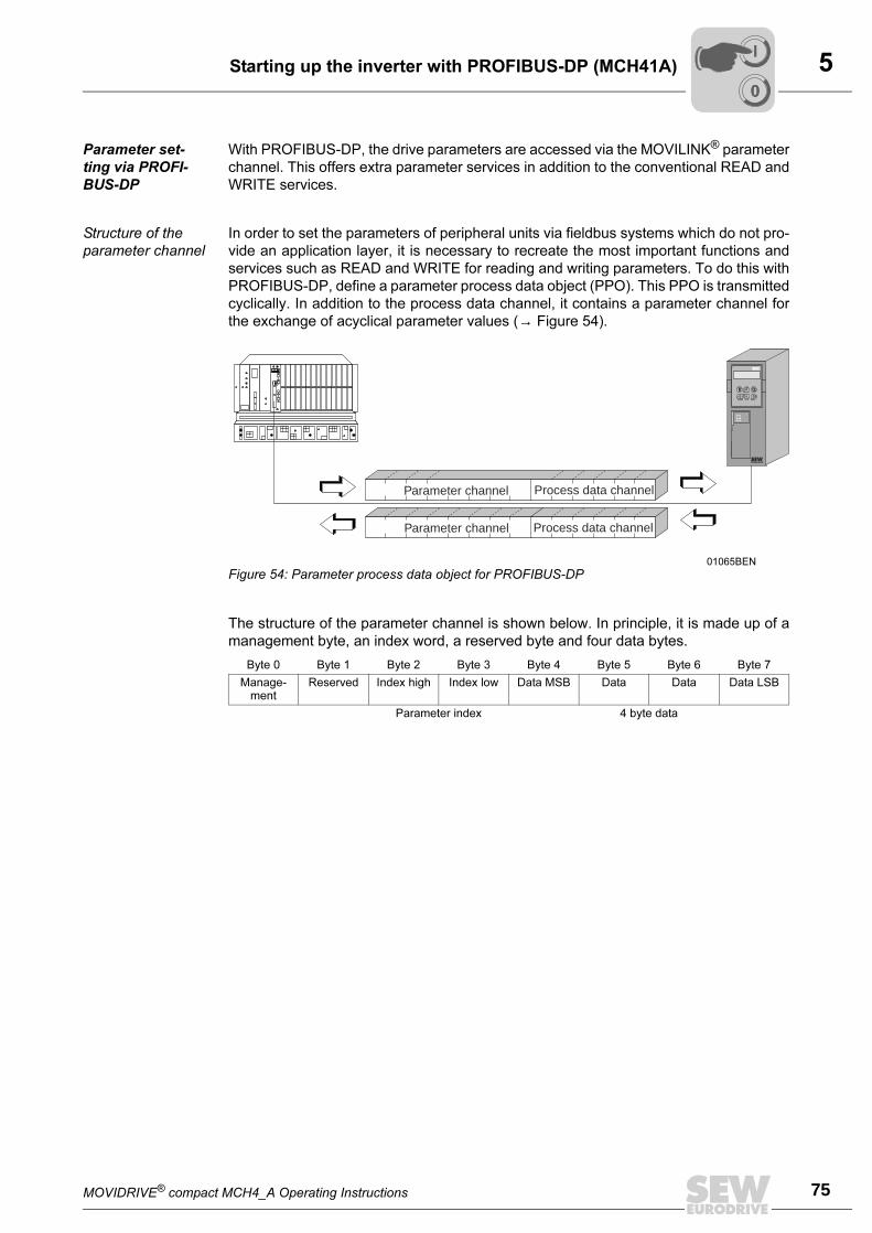
MOVIDRIVE® compact MCH4_A Operating Instructions 75
5Starting up the inverter with PROFIBUS-DP (MCH41A)
Parameter set-
ting via PROFI-
BUS-DP
With PROFIBUS-DP, the drive parameters are accessed via the MOVILINK® parameter
channel. This offers extra parameter services in addition to the conventional READ and
WRITE services.
Structure of the
parameter channel
In order to set the parameters of peripheral units via fieldbus systems which do not pro-
vide an application layer, it is necessary to recreate the most important functions and
services such as READ and WRITE for reading and writing parameters. To do this with
PROFIBUS-DP, define a parameter process data object (PPO). This PPO is transmitted
cyclically. In addition to the process data channel, it contains a parameter channel for
the exchange of acyclical parameter values (→ Figure 54).
The structure of the parameter channel is shown below. In principle, it is made up of a
management byte, an index word, a reserved byte and four data bytes.
01065BEN
Figure 54: Parameter process data object for PROFIBUS-DP
Byte 0 Byte 1 Byte 2 Byte 3 Byte 4 Byte 5 Byte 6 Byte 7
Manage-ment
Reserved Index high Index low Data MSB Data Data Data LSB
Parameter index 4 byte data
E Q
Parameter channel
Parameter channel
Process data channel
Process data channel
00
I
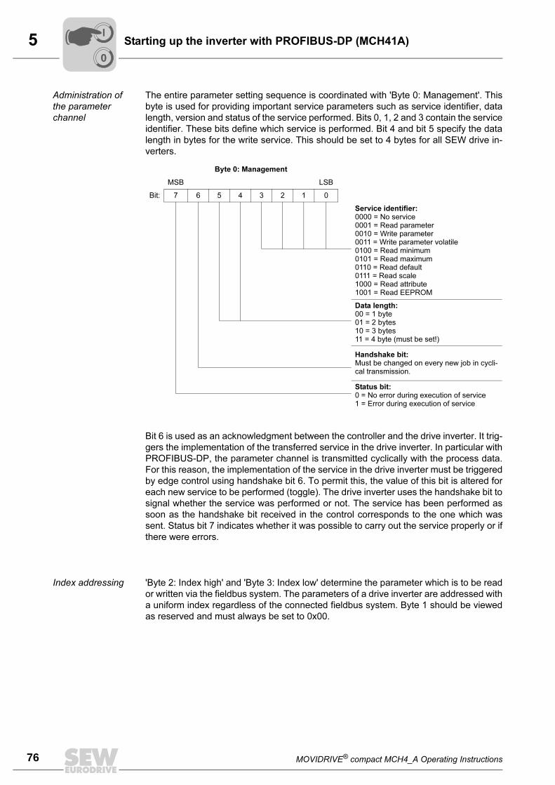
5
76 MOVIDRIVE® compact MCH4_A Operating Instructions
Starting up the inverter with PROFIBUS-DP (MCH41A)
Administration of
the parameter
channel
The entire parameter setting sequence is coordinated with 'Byte 0: Management'. This
byte is used for providing important service parameters such as service identifier, data
length, version and status of the service performed. Bits 0, 1, 2 and 3 contain the service
identifier. These bits define which service is performed. Bit 4 and bit 5 specify the data
length in bytes for the write service. This should be set to 4 bytes for all SEW drive in-
verters.
Bit 6 is used as an acknowledgment between the controller and the drive inverter. It trig-
gers the implementation of the transferred service in the drive inverter. In particular with
PROFIBUS-DP, the parameter channel is transmitted cyclically with the process data.
For this reason, the implementation of the service in the drive inverter must be triggered
by edge control using handshake bit 6. To permit this, the value of this bit is altered for
each new service to be performed (toggle). The drive inverter uses the handshake bit to
signal whether the service was performed or not. The service has been performed as
soon as the handshake bit received in the control corresponds to the one which was
sent. Status bit 7 indicates whether it was possible to carry out the service properly or if
there were errors.
Index addressing 'Byte 2: Index high' and 'Byte 3: Index low' determine the parameter which is to be read
or written via the fieldbus system. The parameters of a drive inverter are addressed with
a uniform index regardless of the connected fieldbus system. Byte 1 should be viewed
as reserved and must always be set to 0x00.
Byte 0: Management
MSB LSB
Bit: 7 6 5 4 3 2 1 0
Service identifier:0000 = No service0001 = Read parameter0010 = Write parameter0011 = Write parameter volatile0100 = Read minimum0101 = Read maximum0110 = Read default0111 = Read scale1000 = Read attribute1001 = Read EEPROM
Data length:00 = 1 byte01 = 2 bytes10 = 3 bytes11 = 4 byte (must be set!)
Handshake bit:Must be changed on every new job in cycli-cal transmission.
Status bit:0 = No error during execution of service1 = Error during execution of service
00
I
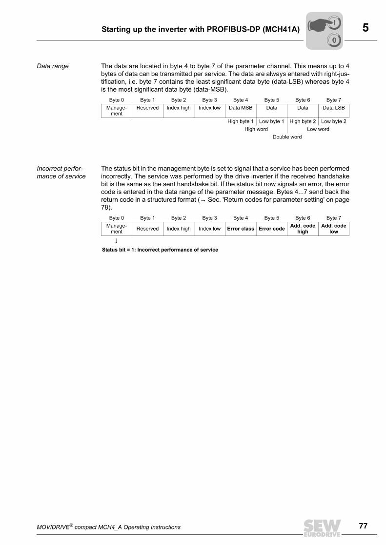
MOVIDRIVE® compact MCH4_A Operating Instructions 77
5Starting up the inverter with PROFIBUS-DP (MCH41A)
Data range The data are located in byte 4 to byte 7 of the parameter channel. This means up to 4
bytes of data can be transmitted per service. The data are always entered with right-jus-
tification, i.e. byte 7 contains the least significant data byte (data-LSB) whereas byte 4
is the most significant data byte (data-MSB).
Incorrect perfor-
mance of service
The status bit in the management byte is set to signal that a service has been performed
incorrectly. The service was performed by the drive inverter if the received handshake
bit is the same as the sent handshake bit. If the status bit now signals an error, the error
code is entered in the data range of the parameter message. Bytes 4...7 send back the
return code in a structured format (→ Sec. 'Return codes for parameter setting' on page
78).
Byte 0 Byte 1 Byte 2 Byte 3 Byte 4 Byte 5 Byte 6 Byte 7
Manage-ment
Reserved Index high Index low Data MSB Data Data Data LSB
High byte 1 Low byte 1 High byte 2 Low byte 2
High word Low word
Double word
Byte 0 Byte 1 Byte 2 Byte 3 Byte 4 Byte 5 Byte 6 Byte 7
Manage-ment
Reserved Index high Index low Error class Error codeAdd. code
highAdd. code
low
↓Status bit = 1: Incorrect performance of service
00
I
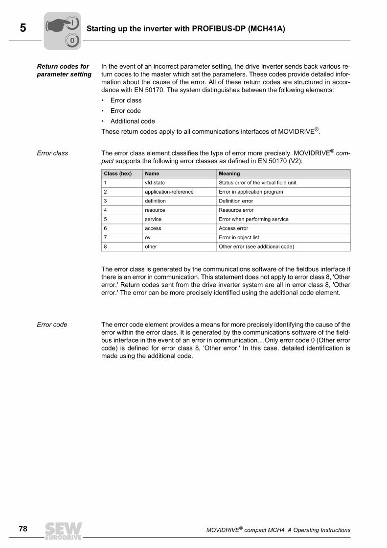
5
78 MOVIDRIVE® compact MCH4_A Operating Instructions
Starting up the inverter with PROFIBUS-DP (MCH41A)
Return codes for
parameter setting
In the event of an incorrect parameter setting, the drive inverter sends back various re-
turn codes to the master which set the parameters. These codes provide detailed infor-
mation about the cause of the error. All of these return codes are structured in accor-
dance with EN 50170. The system distinguishes between the following elements:
• Error class
• Error code
• Additional code
These return codes apply to all communications interfaces of MOVIDRIVE®.
Error class The error class element classifies the type of error more precisely. MOVIDRIVE® com-
pact supports the following error classes as defined in EN 50170 (V2):
The error class is generated by the communications software of the fieldbus interface if
there is an error in communication. This statement does not apply to error class 8, 'Other
error.' Return codes sent from the drive inverter system are all in error class 8, 'Other
error.' The error can be more precisely identified using the additional code element.
Error code The error code element provides a means for more precisely identifying the cause of the
error within the error class. It is generated by the communications software of the field-
bus interface in the event of an error in communication....Only error code 0 (Other error
code) is defined for error class 8, 'Other error.' In this case, detailed identification is
made using the additional code.
Class (hex) Name Meaning
1 vfd-state Status error of the virtual field unit
2 application-reference Error in application program
3 definition Definition error
4 resource Resource error
5 service Error when performing service
6 access Access error
7 ov Error in object list
8 other Other error (see additional code)
00
I
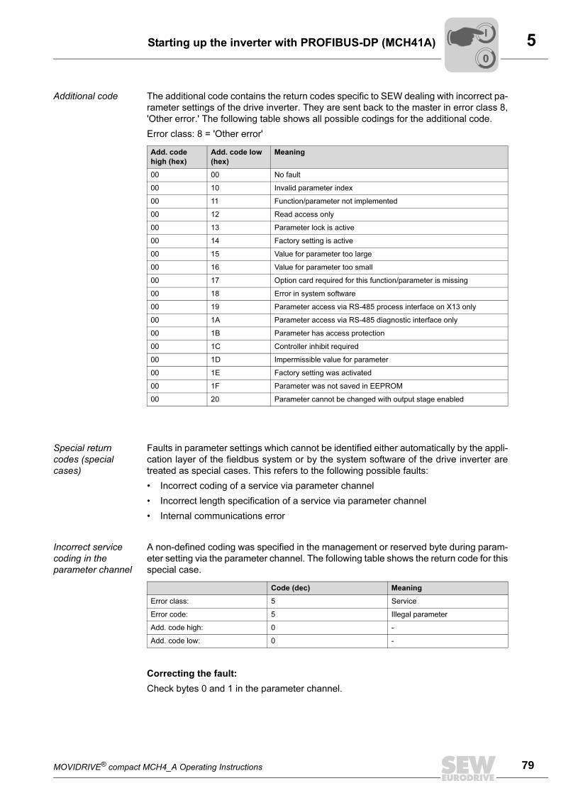
MOVIDRIVE® compact MCH4_A Operating Instructions 79
5Starting up the inverter with PROFIBUS-DP (MCH41A)
Additional code The additional code contains the return codes specific to SEW dealing with incorrect pa-
rameter settings of the drive inverter. They are sent back to the master in error class 8,
'Other error.' The following table shows all possible codings for the additional code.
Error class: 8 = 'Other error'
Special return
codes (special
cases)
Faults in parameter settings which cannot be identified either automatically by the appli-
cation layer of the fieldbus system or by the system software of the drive inverter are
treated as special cases. This refers to the following possible faults:
• Incorrect coding of a service via parameter channel
• Incorrect length specification of a service via parameter channel
• Internal communications error
Incorrect service
coding in the
parameter channel
A non-defined coding was specified in the management or reserved byte during param-
eter setting via the parameter channel. The following table shows the return code for this
special case.
Correcting the fault:
Check bytes 0 and 1 in the parameter channel.
Add. code
high (hex)
Add. code low
(hex)
Meaning
00 00 No fault
00 10 Invalid parameter index
00 11 Function/parameter not implemented
00 12 Read access only
00 13 Parameter lock is active
00 14 Factory setting is active
00 15 Value for parameter too large
00 16 Value for parameter too small
00 17 Option card required for this function/parameter is missing
00 18 Error in system software
00 19 Parameter access via RS-485 process interface on X13 only
00 1A Parameter access via RS-485 diagnostic interface only
00 1B Parameter has access protection
00 1C Controller inhibit required
00 1D Impermissible value for parameter
00 1E Factory setting was activated
00 1F Parameter was not saved in EEPROM
00 20 Parameter cannot be changed with output stage enabled
Code (dec) Meaning
Error class: 5 Service
Error code: 5 Illegal parameter
Add. code high: 0 -
Add. code low: 0 -
00
I
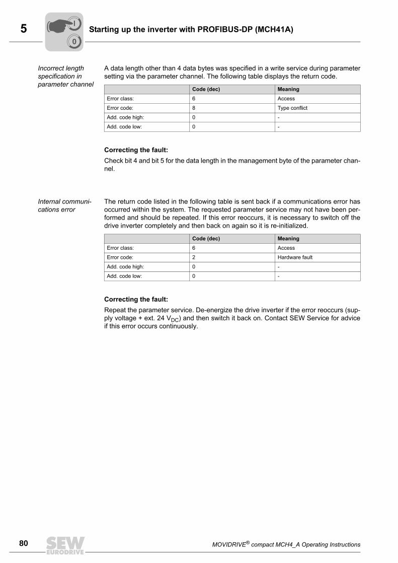
5
80 MOVIDRIVE® compact MCH4_A Operating Instructions
Starting up the inverter with PROFIBUS-DP (MCH41A)
Incorrect length
specification in
parameter channel
A data length other than 4 data bytes was specified in a write service during parameter
setting via the parameter channel. The following table displays the return code.
Correcting the fault:
Check bit 4 and bit 5 for the data length in the management byte of the parameter chan-
nel.
Internal communi-
cations error
The return code listed in the following table is sent back if a communications error has
occurred within the system. The requested parameter service may not have been per-
formed and should be repeated. If this error reoccurs, it is necessary to switch off the
drive inverter completely and then back on again so it is re-initialized.
Correcting the fault:
Repeat the parameter service. De-energize the drive inverter if the error reoccurs (sup-
ply voltage + ext. 24 VDC) and then switch it back on. Contact SEW Service for advice
if this error occurs continuously.
Code (dec) Meaning
Error class: 6 Access
Error code: 8 Type conflict
Add. code high: 0 -
Add. code low: 0 -
Code (dec) Meaning
Error class: 6 Access
Error code: 2 Hardware fault
Add. code high: 0 -
Add. code low: 0 -
00
I
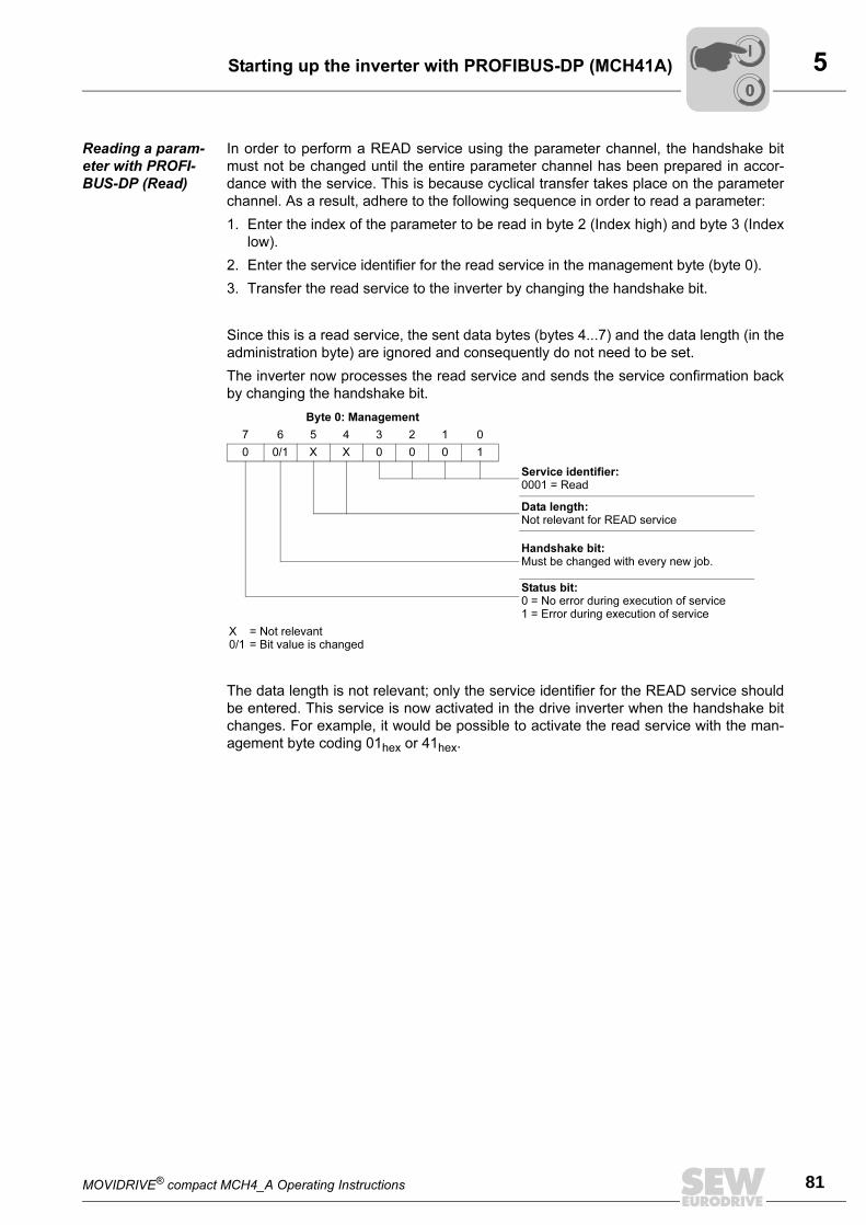
MOVIDRIVE® compact MCH4_A Operating Instructions 81
5Starting up the inverter with PROFIBUS-DP (MCH41A)
Reading a param-
eter with PROFI-
BUS-DP (Read)
In order to perform a READ service using the parameter channel, the handshake bit
must not be changed until the entire parameter channel has been prepared in accor-
dance with the service. This is because cyclical transfer takes place on the parameter
channel. As a result, adhere to the following sequence in order to read a parameter:
1. Enter the index of the parameter to be read in byte 2 (Index high) and byte 3 (Index
low).
2. Enter the service identifier for the read service in the management byte (byte 0).
3. Transfer the read service to the inverter by changing the handshake bit.
Since this is a read service, the sent data bytes (bytes 4...7) and the data length (in the
administration byte) are ignored and consequently do not need to be set.
The inverter now processes the read service and sends the service confirmation back
by changing the handshake bit.
The data length is not relevant; only the service identifier for the READ service should
be entered. This service is now activated in the drive inverter when the handshake bit
changes. For example, it would be possible to activate the read service with the man-
agement byte coding 01hex or 41hex.
Byte 0: Management
7 6 5 4 3 2 1 0
0 0/1 X X 0 0 0 1
Service identifier:0001 = Read
Data length:Not relevant for READ service
Handshake bit:Must be changed with every new job.
Status bit:0 = No error during execution of service1 = Error during execution of service
X = Not relevant0/1 = Bit value is changed
00
I
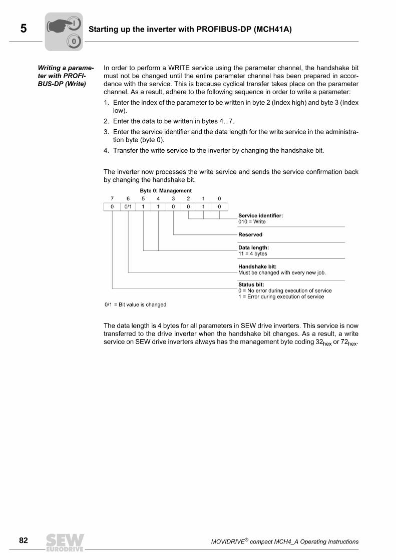
5
82 MOVIDRIVE® compact MCH4_A Operating Instructions
Starting up the inverter with PROFIBUS-DP (MCH41A)
Writing a parame-
ter with PROFI-
BUS-DP (Write)
In order to perform a WRITE service using the parameter channel, the handshake bit
must not be changed until the entire parameter channel has been prepared in accor-
dance with the service. This is because cyclical transfer takes place on the parameter
channel. As a result, adhere to the following sequence in order to write a parameter:
1. Enter the index of the parameter to be written in byte 2 (Index high) and byte 3 (Index
low).
2. Enter the data to be written in bytes 4...7.
3. Enter the service identifier and the data length for the write service in the administra-
tion byte (byte 0).
4. Transfer the write service to the inverter by changing the handshake bit.
The inverter now processes the write service and sends the service confirmation back
by changing the handshake bit.
The data length is 4 bytes for all parameters in SEW drive inverters. This service is now
transferred to the drive inverter when the handshake bit changes. As a result, a write
service on SEW drive inverters always has the management byte coding 32hex or 72hex.
Byte 0: Management
7 6 5 4 3 2 1 0
0 0/1 1 1 0 0 1 0
Service identifier:010 = Write
Reserved
Data length:11 = 4 bytes
Handshake bit:Must be changed with every new job.
Status bit:0 = No error during execution of service1 = Error during execution of service
0/1 = Bit value is changed
00
I
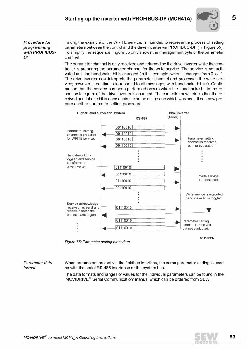
MOVIDRIVE® compact MCH4_A Operating Instructions 83
5Starting up the inverter with PROFIBUS-DP (MCH41A)
Procedure for
programming
with PROFIBUS-
DP
Taking the example of the WRITE service, is intended to represent a process of setting
parameters between the control and the drive inverter via PROFIBUS-DP (→ Figure 55).
To simplify the sequence, Figure 55 only shows the management byte of the parameter
channel.
The parameter channel is only received and returned by the drive inverter while the con-
troller is preparing the parameter channel for the write service. The service is not acti-
vated until the handshake bit is changed (in this example, when it changes from 0 to 1).
The drive inverter now interprets the parameter channel and processes the write ser-
vice; however, it continues to respond to all messages with handshake bit = 0. Confir-
mation that the service has been performed occurs when the handshake bit in the re-
sponse telegram of the drive inverter is changed. The controller now detects that the re-
ceived handshake bit is once again the same as the one which was sent. It can now pre-
pare another parameter setting procedure.
Parameter data
format
When parameters are set via the fieldbus interface, the same parameter coding is used
as with the serial RS-485 interfaces or the system bus.
The data formats and ranges of values for the individual parameters can be found in the
'MOVIDRIVE® Serial Communication' manual which can be ordered from SEW.
00152BEN
Figure 55: Parameter setting procedure
0 1100100
0 1100100
0 1100100
0 1100100
0 1100101
0 1100100
0 1100101
0 1100100
0 1100101
0 1100101
0 1100101
Higher level automatic system
RS-485
Drive Inverter(Slave)
Parameter settingchannel is preparedfor WRITE service.
Handshake bit istoggled and servicetransferred todrive inverter.
Service acknowledgereceived, as send andreceive handshakebits the same again.
Parameter settingchannel is receivedbut not evaluated.
Write service is executed,handshake bit is toggled.
Write serviceis processed.
Parameter settingchannel is receivedbut not evaluated.
00
I
5
84 MOVIDRIVE® compact MCH4_A Operating Instructions
Starting up the inverter with INTERBUS (MCH42A)
5.9 Starting up the inverter with INTERBUS (MCH42A)
The parameters of the MOVIDRIVE® compact MCH42A inverter can be set straight
away via INTERBUS without any further settings once the INTERBUS interface has
been installed. As a result, all parameters can be set by the master automation system
after switch-on.
To do this, the "Control signal source" must be set to FIELDBUS in the inverter (P100 =
FIELDBUS and P101 = FIELDBUS). The FIELDBUS setting means the inverter param-
eters are set for control and setpoint entry via INTERBUS. The inverter then responds
to the process output data transmitted from the programmable master controller.
Activation of the control signal source/setpoint source FIELDBUS is signaled to the ma-
chine control using the 'Fieldbus mode active' bit in the status word. For safety reasons,
the inverter must also be enabled on the terminal side for control via the fieldbus system.
Accordingly, the terminals must be wired up or programmed in such a way that the in-
verter is enabled via the input terminals.
The simplest way of enabling the inverter on the terminal side is to connect the DIØØ (/
CONTROLLER INHIBIT) input terminal to a '1' signal and to program input terminals
DIØ1...DIØ3 to 'NO FUNCTION'.
Preliminary work
for startup
1. Enable the inverter on the terminal side. To do this, apply a '1' signal to X11:1 (DIØØ
'/CONTROLLER INHIBIT'), for example using a jumper to X11:8 (VO24).
2. Only switch on the 24 VDC voltage supply; do not switch on the supply voltage yet.
You can now set the parameters of the inverter without the connected motor starting
up inadvertently.
3. Set the setpoint source and control signal source to FIELDBUS (P100 = FIELDBUS
and P101 = FIELDBUS).
4. Set binary inputs DIØ1...DIØ3 to 'NO FUNCTION' (P600...P602 = 'NO FUNCTION').
00
I
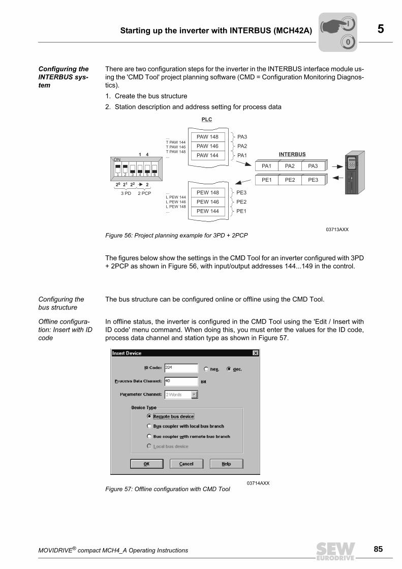
MOVIDRIVE® compact MCH4_A Operating Instructions 85
5Starting up the inverter with INTERBUS (MCH42A)
Configuring the
INTERBUS sys-
tem
There are two configuration steps for the inverter in the INTERBUS interface module us-
ing the 'CMD Tool' project planning software (CMD = Configuration Monitoring Diagnos-
tics).
1. Create the bus structure
2. Station description and address setting for process data
The figures below show the settings in the CMD Tool for an inverter configured with 3PD
+ 2PCP as shown in Figure 56, with input/output addresses 144...149 in the control.
Configuring the
bus structure
The bus structure can be configured online or offline using the CMD Tool.
Offline configura-
tion: Insert with ID
code
In offline status, the inverter is configured in the CMD Tool using the 'Edit / Insert with
ID code' menu command. When doing this, you must enter the values for the ID code,
process data channel and station type as shown in Figure 57.
03713AXX
Figure 56: Project planning example for 3PD + 2PCP
PAW 144
PAW 146
PAW 148
PEW 144
PEW 146
PEW 148
PA1 PA2 PA3
...
L PEW 144
L PEW 146
L PEW 148
...
PE1 PE2 PE3
PA1
PA2
PA3
PE1
PE2
PE3
...
T PAW 144
T PAW 146
T PAW 148
...
PLC
INTERBUS
1 2 3 4 5 6
ON
3 PD 2 PCP
20 2221 2
1 4
03714AXX
Figure 57: Offline configuration with CMD Tool
00
I
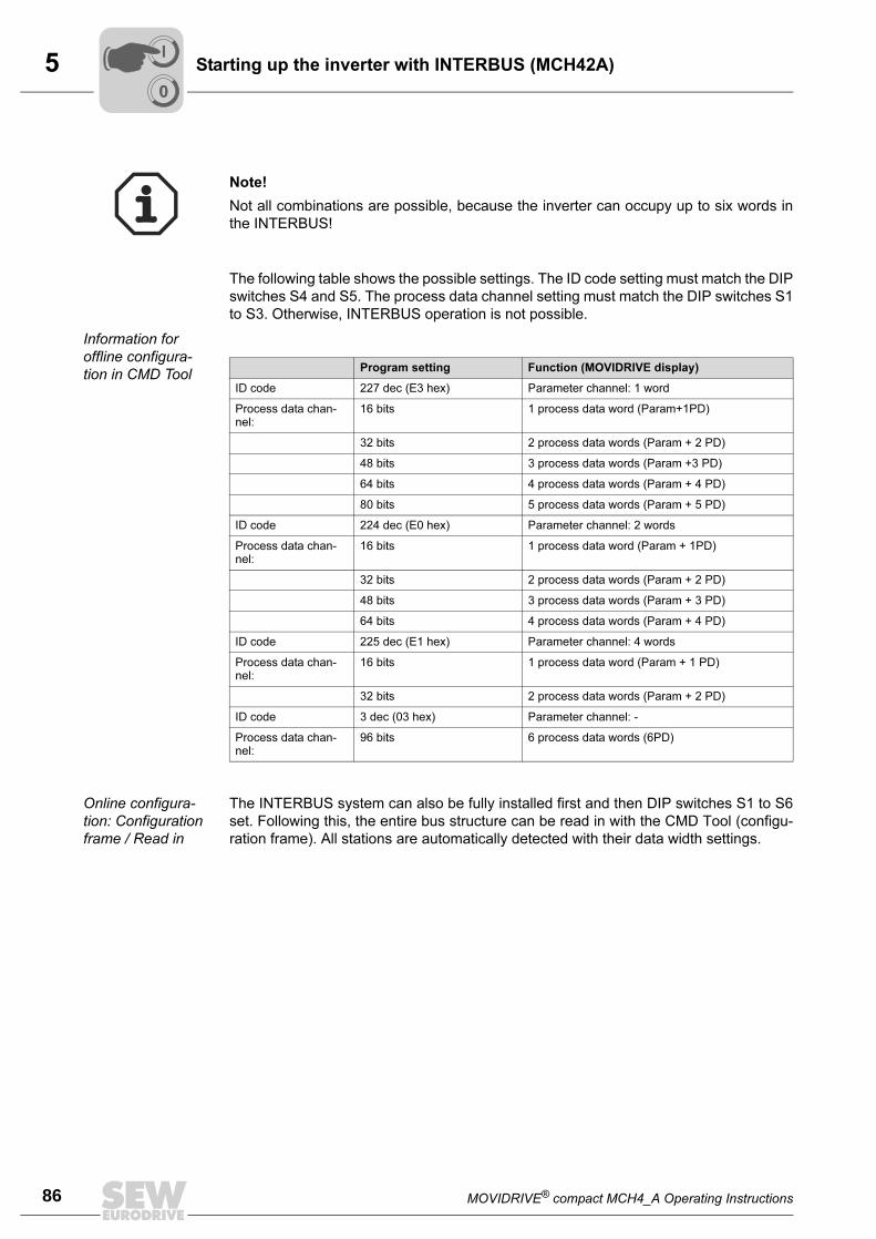
5
86 MOVIDRIVE® compact MCH4_A Operating Instructions
Starting up the inverter with INTERBUS (MCH42A)
The following table shows the possible settings. The ID code setting must match the DIP
switches S4 and S5. The process data channel setting must match the DIP switches S1
to S3. Otherwise, INTERBUS operation is not possible.
Information for
offline configura-
tion in CMD Tool
Online configura-
tion: Configuration
frame / Read in
The INTERBUS system can also be fully installed first and then DIP switches S1 to S6
set. Following this, the entire bus structure can be read in with the CMD Tool (configu-
ration frame). All stations are automatically detected with their data width settings.
Note!
Not all combinations are possible, because the inverter can occupy up to six words in
the INTERBUS!
Program setting Function (MOVIDRIVE display)
ID code 227 dec (E3 hex) Parameter channel: 1 word
Process data chan-nel:
16 bits 1 process data word (Param+1PD)
32 bits 2 process data words (Param + 2 PD)
48 bits 3 process data words (Param +3 PD)
64 bits 4 process data words (Param + 4 PD)
80 bits 5 process data words (Param + 5 PD)
ID code 224 dec (E0 hex) Parameter channel: 2 words
Process data chan-nel:
16 bits 1 process data word (Param + 1PD)
32 bits 2 process data words (Param + 2 PD)
48 bits 3 process data words (Param + 3 PD)
64 bits 4 process data words (Param + 4 PD)
ID code 225 dec (E1 hex) Parameter channel: 4 words
Process data chan-nel:
16 bits 1 process data word (Param + 1 PD)
32 bits 2 process data words (Param + 2 PD)
ID code 3 dec (03 hex) Parameter channel: -
Process data chan-nel:
96 bits 6 process data words (6PD)
00
I
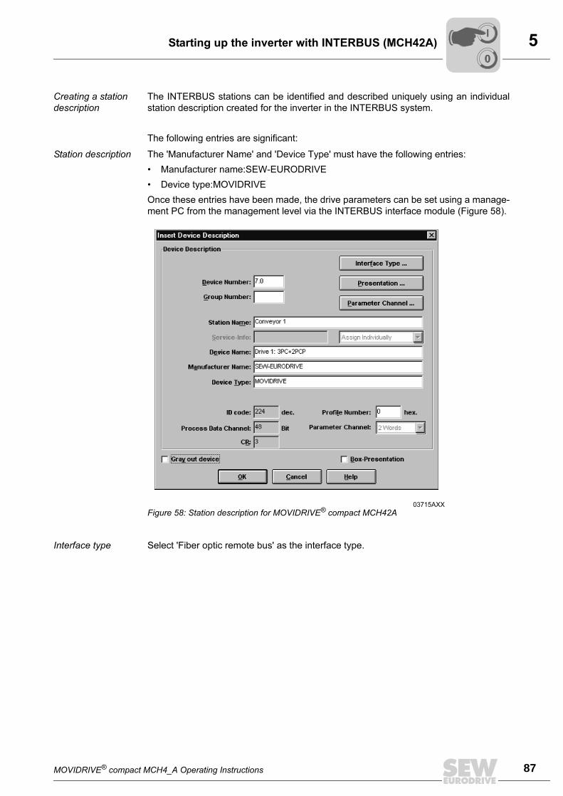
MOVIDRIVE® compact MCH4_A Operating Instructions 87
5Starting up the inverter with INTERBUS (MCH42A)
Creating a station
description
The INTERBUS stations can be identified and described uniquely using an individual
station description created for the inverter in the INTERBUS system.
The following entries are significant:
Station description The 'Manufacturer Name' and 'Device Type' must have the following entries:
• Manufacturer name:SEW-EURODRIVE
• Device type:MOVIDRIVE
Once these entries have been made, the drive parameters can be set using a manage-
ment PC from the management level via the INTERBUS interface module (Figure 58).
Interface type Select 'Fiber optic remote bus' as the interface type.
03715AXX
Figure 58: Station description for MOVIDRIVE® compact MCH42A
00
I
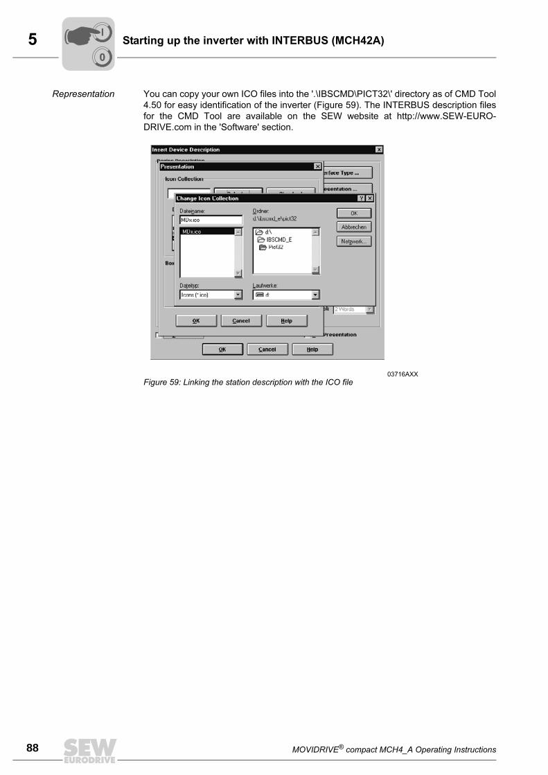
5
88 MOVIDRIVE® compact MCH4_A Operating Instructions
Starting up the inverter with INTERBUS (MCH42A)
Representation You can copy your own ICO files into the '.\IBSCMD\PICT32\' directory as of CMD Tool
4.50 for easy identification of the inverter (Figure 59). The INTERBUS description files
for the CMD Tool are available on the SEW website at http://www.SEW-EURO-
DRIVE.com in the 'Software' section.
03716AXX
Figure 59: Linking the station description with the ICO file
00
I
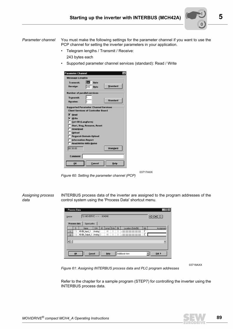
MOVIDRIVE® compact MCH4_A Operating Instructions 89
5Starting up the inverter with INTERBUS (MCH42A)
Parameter channel You must make the following settings for the parameter channel if you want to use the
PCP channel for setting the inverter parameters in your application.
• Telegram lengths / Transmit / Receive:
243 bytes each
• Supported parameter channel services (standard): Read / Write
Assigning process
data
INTERBUS process data of the inverter are assigned to the program addresses of the
control system using the 'Process Data' shortcut menu.
Refer to the chapter for a sample program (STEP7) for controlling the inverter using the
INTERBUS process data.
03717AXX
Figure 60: Setting the parameter channel (PCP)
03718AXX
Figure 61: Assigning INTERBUS process data and PLC program addresses
00
I
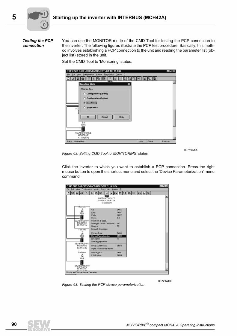
5
90 MOVIDRIVE® compact MCH4_A Operating Instructions
Starting up the inverter with INTERBUS (MCH42A)
Testing the PCP
connection
You can use the MONITOR mode of the CMD Tool for testing the PCP connection to
the inverter. The following figures illustrate the PCP test procedure. Basically, this meth-
od involves establishing a PCP connection to the unit and reading the parameter list (ob-
ject list) stored in the unit.
Set the CMD Tool to 'Monitoring' status.
Click the inverter to which you want to establish a PCP connection. Press the right
mouse button to open the shortcut menu and select the 'Device Parameterization' menu
command.
03719AXX
Figure 62: Setting CMD Tool to 'MONITORING' status
03721AXX
Figure 63: Testing the PCP device parameterization
00
I
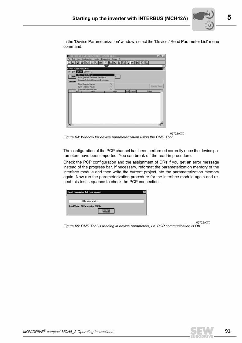
MOVIDRIVE® compact MCH4_A Operating Instructions 91
5Starting up the inverter with INTERBUS (MCH42A)
In the 'Device Parameterization' window, select the 'Device / Read Parameter List' menu
command.
The configuration of the PCP channel has been performed correctly once the device pa-
rameters have been imported. You can break off the read-in procedure.
Check the PCP configuration and the assignment of CRs if you get an error message
instead of the progress bar. If necessary, reformat the parameterization memory of the
interface module and then write the current project into the parameterization memory
again. Now run the parameterization procedure for the interface module again and re-
peat this test sequence to check the PCP connection.
03722AXX
Figure 64: Window for device parameterization using the CMD Tool
03723AXX
Figure 65: CMD Tool is reading in device parameters, i.e. PCP communication is OK
00
I
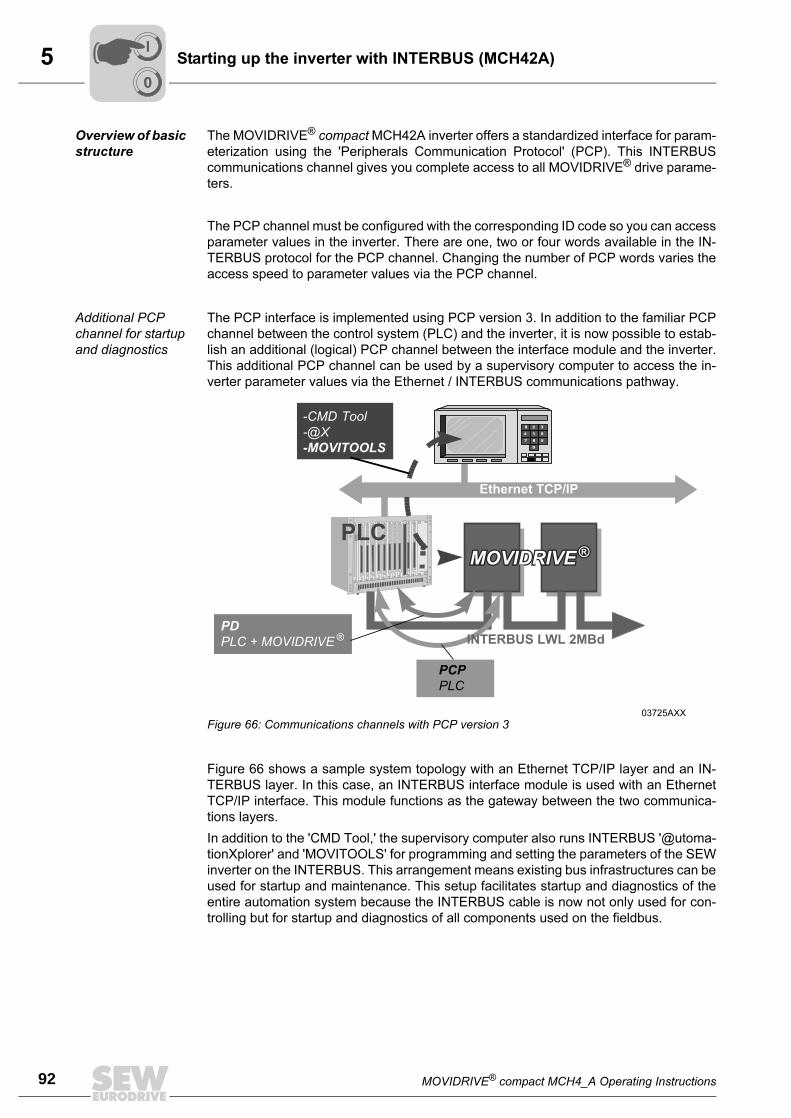
5
92 MOVIDRIVE® compact MCH4_A Operating Instructions
Starting up the inverter with INTERBUS (MCH42A)
Overview of basic
structure
The MOVIDRIVE® compact MCH42A inverter offers a standardized interface for param-
eterization using the 'Peripherals Communication Protocol' (PCP). This INTERBUS
communications channel gives you complete access to all MOVIDRIVE® drive parame-
ters.
The PCP channel must be configured with the corresponding ID code so you can access
parameter values in the inverter. There are one, two or four words available in the IN-
TERBUS protocol for the PCP channel. Changing the number of PCP words varies the
access speed to parameter values via the PCP channel.
Additional PCP
channel for startup
and diagnostics
The PCP interface is implemented using PCP version 3. In addition to the familiar PCP
channel between the control system (PLC) and the inverter, it is now possible to estab-
lish an additional (logical) PCP channel between the interface module and the inverter.
This additional PCP channel can be used by a supervisory computer to access the in-
verter parameter values via the Ethernet / INTERBUS communications pathway.
Figure 66 shows a sample system topology with an Ethernet TCP/IP layer and an IN-
TERBUS layer. In this case, an INTERBUS interface module is used with an Ethernet
TCP/IP interface. This module functions as the gateway between the two communica-
tions layers.
In addition to the 'CMD Tool,' the supervisory computer also runs INTERBUS '@utoma-
tionXplorer' and 'MOVITOOLS' for programming and setting the parameters of the SEW
inverter on the INTERBUS. This arrangement means existing bus infrastructures can be
used for startup and maintenance. This setup facilitates startup and diagnostics of the
entire automation system because the INTERBUS cable is now not only used for con-
trolling but for startup and diagnostics of all components used on the fieldbus.
03725AXX
Figure 66: Communications channels with PCP version 3
Ethernet TCP/IP
PLC
-CMD Tool
-@X
-MOVITOOLS
PD
PLC + MOVIDRIVE ®
PCP
PLC
INTERBUS LWL 2MBd
MOVIDRIVE®
MOVIDRIVE®
MOVIDRIVE®
00
I
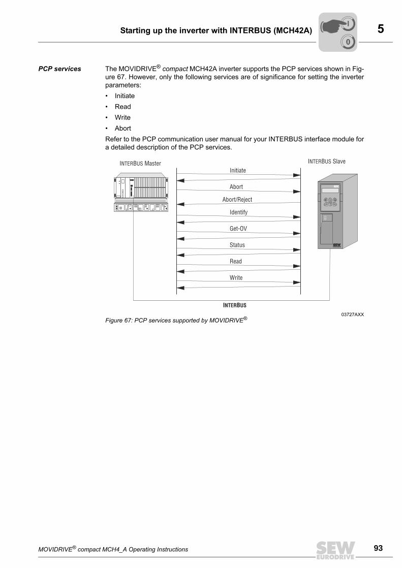
MOVIDRIVE® compact MCH4_A Operating Instructions 93
5Starting up the inverter with INTERBUS (MCH42A)
PCP services The MOVIDRIVE® compact MCH42A inverter supports the PCP services shown in Fig-
ure 67. However, only the following services are of significance for setting the inverter
parameters:
• Initiate
• Read
• Write
• Abort
Refer to the PCP communication user manual for your INTERBUS interface module for
a detailed description of the PCP services.
03727AXX
Figure 67: PCP services supported by MOVIDRIVE®
I B MasterNTER US I B SlaveNTER US
Initiate
Abort
Abort/Reject
Identify
Get-OV
Status
Read
Write
I BNTER US
E Q
00
I
5
94 MOVIDRIVE® compact MCH4_A Operating Instructions
Starting up the inverter with INTERBUS (MCH42A)
Establishing the
communications
link with 'Initiate'
The 'Initiate' PCP service establishes a communications link for exchanging parameters
between an INTERBUS interface module and the MOVIDRIVE® inverter. Communica-
tion is always established from the INTERBUS interface module. Various arrangements
relating to the communications link are checked during establishment of the connection,
such as supported PCP services, user data length, etc. The inverter responds with a
positive initiate response if the connection is established successfully. If the connection
could not be established, then the arrangements for the communications link on the IN-
TERBUS interface module do not match those on the MOVIDRIVE® inverter. The invert-
er responds with an initiate error response. In this case, compare the configured com-
munications relationship list in the INTERBUS interface module with that in the inverter.
As a rule, an attempt to re-establish an existing communications link leads to an abort.
The communications link is then dropped, which means the 'Initiate' PCP service has to
be run for a third time in order to re-establish the communications connection.
Breaking off the
communications
link with 'Abort'
The 'Abort' PCP service breaks off an existing communications link between the INTER-
BUS interface module and the MOVIDRIVE® inverter. Abort is an unconfirmed PCP ser-
vice and can be triggered either from the INTERBUS interface module or from MOVID-
RIVE®.
Reading parame-
ter values with
'Read'
The 'Read' PCP service gives the INTERBUS interface module read access to all com-
munications objects (drive parameters) of the MOVIDRIVE® inverter. All drive parame-
ters and their coding are presented in detail in the Fieldbus Unit Profile documentation
and the list of MOVIDRIVE® parameters.
Writing parameter
values with 'Write'
The 'Write' PCP service gives the INTERBUS interface module write access to all MOV-
IDRIVE® drive parameters. The inverter generates a write error response if incorrect ac-
cess is made to a drive parameter (e.g. the written value is too great). Precise informa-
tion is given relating to the cause of the error.
00
I
MOVIDRIVE® compact MCH4_A Operating Instructions 95
5Starting up the inverter with INTERBUS (MCH42A)
Parameters in the
object list
The 'Read' and 'Write' PCP services give the INTERBUS interface module access to all
parameters defined in the object list. All drive parameters which can be accessed via the
bus system are described as communications objects in the static object list. All objects
in the static object list are addressed using indices. The following table shows the struc-
ture of the object list for the MOVIDRIVE® compact MCH42A inverter.
The index range is subdivided into three logical areas. The drive parameters are ad-
dressed using indices 8300...8800dec. Refer to the MOVIDRIVE® parameter list in the
SEW documentation for information about the parameter index. Indices below 8300dec
are handled directly on the INTERBUS interface and are not to be viewed as drive pa-
rameters.
Object description
of the drive param-
eters
The drive parameters of the MOVIDRIVE® inverter are described in detail in the MOV-
IDRIVE® parameter list in the SEW documentation. In addition to the parameter index,
you will receive additional information about coding, the range of values and the mean-
ing of the parameter data.
The object description in the object list is identical for all drive parameters. Even those
parameters which can only be read are given the Read all/Write all attribute in the object
list, because the inverter undertakes the corresponding check itself and sends back a
return code if necessary. The following table shows the object description of all drive pa-
rameters.
Parameter index (decimal) Name of the communications object
8296 Download parameter block
8297 Last PCP index
8298 MOVILINK® parameter channel cyclical
8299 MOVILINK® parameter channel acyclical
8300...8800 Drive parameter for MOVIDRIVE® (can be accessed directly with the 'Read' and 'Write' PCP services, see the MOVIDRIVE® parameter list in the SEW documentation for information about the parameter index)
8801...9999 Drive parameters for MOVIDRIVE® (these parameters can only be accessed via the MOVILINK® parameter channel)
>10000 Table, program and variable memory (these parameters can only be accessed via the MOVILINK® parameter channel)
Index: 8300...8800
Object code: 7 (simple variable)
Data type index: 10 (octet string)
Length: 4
Local address:
Password:
Access groups:
Access rights: Read all/Write all
Name[16]: -
Extension length: -
00
I
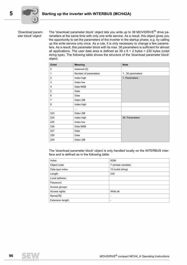
5
96 MOVIDRIVE® compact MCH4_A Operating Instructions
Starting up the inverter with INTERBUS (MCH42A)
'Download param-
eter block' object
The 'download parameter block' object lets you write up to 38 MOVIDRIVE® drive pa-
rameters at the same time with only one write service. As a result, this object gives you
the opportunity to set the parameters of the inverter in the startup phase, e.g. by calling
up the write service only once. As a rule, it is only necessary to change a few parame-
ters. As a result, this parameter block with its max. 38 parameters is sufficient for almost
all applications. The user data area is defined as 38 x 6 + 2 bytes = 230 bytes (octet
string type). The following table shows the structure of the 'download parameter block'
object.
The 'download parameter block' object is only handled locally on the INTERBUS inter-
face and is defined as in the following table.
Octet Meaning Note
0 reserved (0)
1 Number of parameters 1...38 parameters
2 Index high 1. Parameters
3 Index low
4 Data MSB
5 Data
6 Data
7 Data LSB
8 Index high
... ...
223 Data LSB
224 Index high 38. Parameters
225 Index low
226 Data MSB
227 Data
228 Data
229 Data LSB
Index: 8296
Object code: 7 (simple variable)
Data type index: 10 (octet string)
Length: 230
Local address:
Password:
Access groups:
Access rights: Write all
Name[16]: -
Extension length: -
00
I
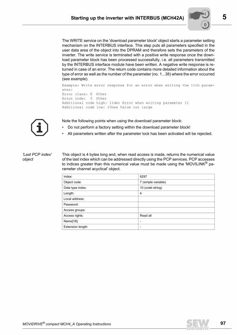
MOVIDRIVE® compact MCH4_A Operating Instructions 97
5Starting up the inverter with INTERBUS (MCH42A)
The WRITE service on the 'download parameter block' object starts a parameter setting
mechanism on the INTERBUS interface. This step puts all parameters specified in the
user data area of the object into the DPRAM and therefore sets the parameters of the
inverter. The write service is terminated with a positive write response once the down-
load parameter block has been processed successfully, i.e. all parameters transmitted
by the INTERBUS interface module have been written. A negative write response is re-
turned in case of an error. The return code contains more detailed information about the
type of error as well as the number of the parameter (no. 1...38) where the error occurred
(see example).
Example: Write error response for an error when writing the 11th param-
eter:
Error class: 8 Other
Error code: 0 Other
Additional code high: 11dec Error when writing parameter 11
Additional code low: 15hex Value too large
'Last PCP index'
object
This object is 4 bytes long and, when read access is made, returns the numerical value
of the last index which can be addressed directly using the PCP services. PCP accesses
to indices greater than this numerical value must be made using the 'MOVILINK® pa-
rameter channel acyclical' object.
Note the following points when using the download parameter block:
• Do not perform a factory setting within the download parameter block!
• All parameters written after the parameter lock has been activated will be rejected.
Index: 8297
Object code: 7 (simple variable)
Data type index: 10 (octet string)
Length: 4
Local address:
Password:
Access groups:
Access rights: Read all
Name[16]: -
Extension length: -
00
I
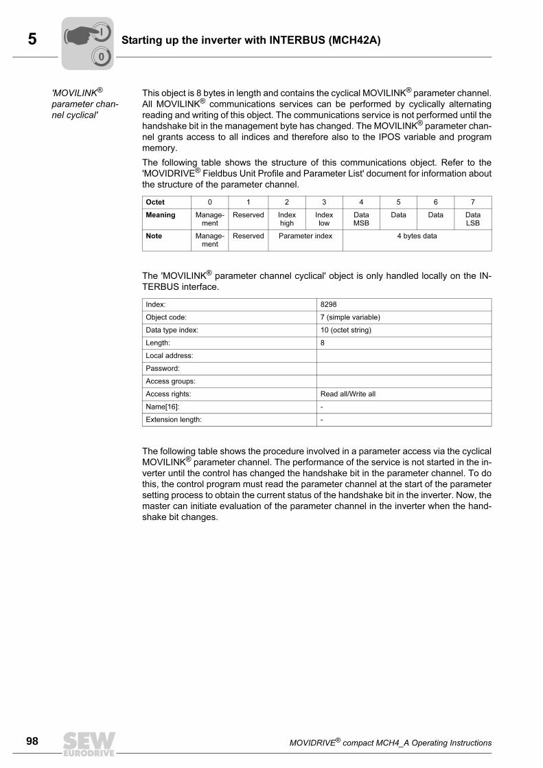
5
98 MOVIDRIVE® compact MCH4_A Operating Instructions
Starting up the inverter with INTERBUS (MCH42A)
'MOVILINK®
parameter chan-
nel cyclical'
This object is 8 bytes in length and contains the cyclical MOVILINK® parameter channel.
All MOVILINK® communications services can be performed by cyclically alternating
reading and writing of this object. The communications service is not performed until the
handshake bit in the management byte has changed. The MOVILINK® parameter chan-
nel grants access to all indices and therefore also to the IPOS variable and program
memory.
The following table shows the structure of this communications object. Refer to the
'MOVIDRIVE® Fieldbus Unit Profile and Parameter List' document for information about
the structure of the parameter channel.
The 'MOVILINK® parameter channel cyclical' object is only handled locally on the IN-
TERBUS interface.
The following table shows the procedure involved in a parameter access via the cyclical
MOVILINK® parameter channel. The performance of the service is not started in the in-
verter until the control has changed the handshake bit in the parameter channel. To do
this, the control program must read the parameter channel at the start of the parameter
setting process to obtain the current status of the handshake bit in the inverter. Now, the
master can initiate evaluation of the parameter channel in the inverter when the hand-
shake bit changes.
Octet 0 1 2 3 4 5 6 7
Meaning Manage-ment
Reserved Index high
Index low
Data MSB
Data Data Data LSB
Note Manage-ment
Reserved Parameter index 4 bytes data
Index: 8298
Object code: 7 (simple variable)
Data type index: 10 (octet string)
Length: 8
Local address:
Password:
Access groups:
Access rights: Read all/Write all
Name[16]: -
Extension length: -
00
I
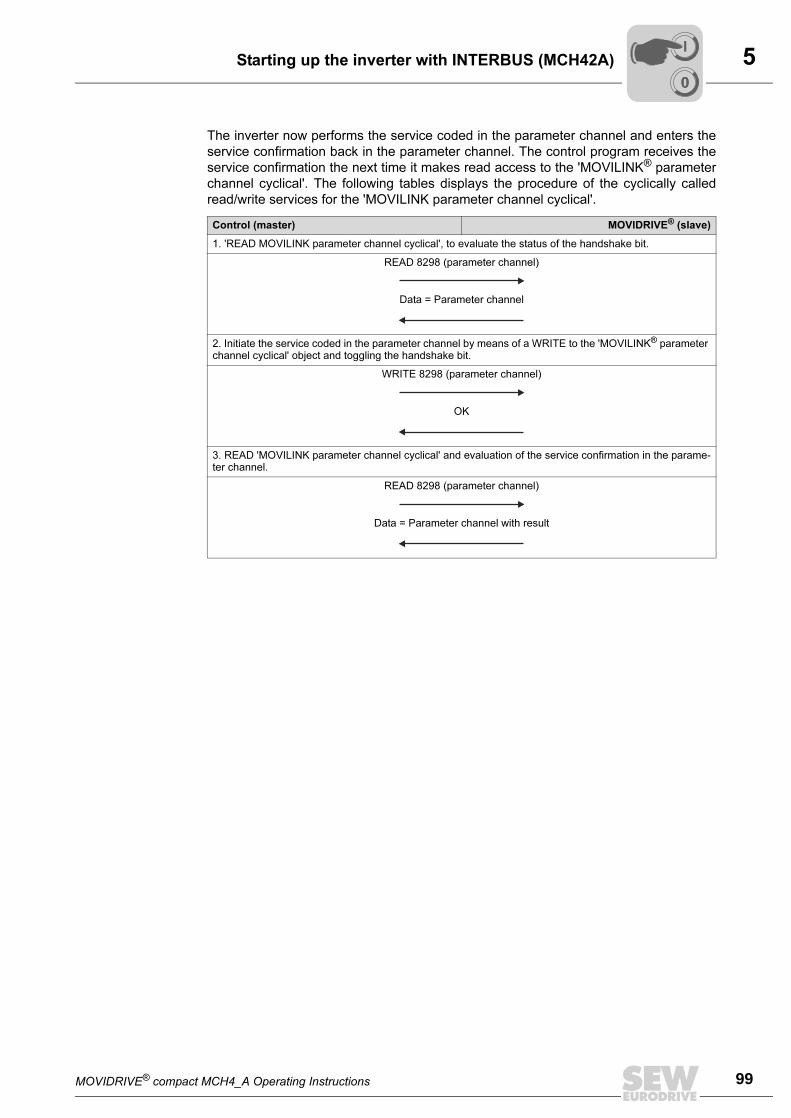
MOVIDRIVE® compact MCH4_A Operating Instructions 99
5Starting up the inverter with INTERBUS (MCH42A)
The inverter now performs the service coded in the parameter channel and enters the
service confirmation back in the parameter channel. The control program receives the
service confirmation the next time it makes read access to the 'MOVILINK® parameter
channel cyclical'. The following tables displays the procedure of the cyclically called
read/write services for the 'MOVILINK parameter channel cyclical'.
Control (master) MOVIDRIVE® (slave)
1. 'READ MOVILINK parameter channel cyclical', to evaluate the status of the handshake bit.
READ 8298 (parameter channel)
Data = Parameter channel
2. Initiate the service coded in the parameter channel by means of a WRITE to the 'MOVILINK® parameter channel cyclical' object and toggling the handshake bit.
WRITE 8298 (parameter channel)
OK
3. READ 'MOVILINK parameter channel cyclical' and evaluation of the service confirmation in the parame-ter channel.
READ 8298 (parameter channel)
Data = Parameter channel with result
00
I
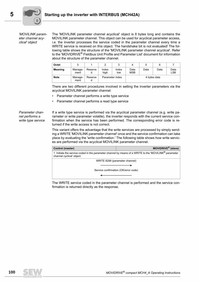
5
100 MOVIDRIVE® compact MCH4_A Operating Instructions
Starting up the inverter with INTERBUS (MCH42A)
'MOVILINK param-
eter channel acy-
clical' object
The 'MOVILINK parameter channel acyclical' object is 8 bytes long and contains the
MOVILINK parameter channel. This object can be used for acyclical parameter access,
i.e. the inverter processes the service coded in the parameter channel every time a
WRITE service is received on this object. The handshake bit is not evaluated! The fol-
lowing table shows the structure of the 'MOVILINK parameter channel acyclical'. Refer
to the 'MOVIDRIVE® Fieldbus Unit Profile and Parameter List' document for information
about the structure of the parameter channel.
There are two different procedures involved in setting the inverter parameters via the
acyclical MOVILINK parameter channel:
• Parameter channel performs a write type service
• Parameter channel performs a read type service
Parameter chan-
nel performs a
write type service
If a write type service is performed via the acyclical parameter channel (e.g. write pa-
rameter or write parameter volatile), the inverter responds with the current service con-
firmation when the service has been performed. The corresponding error code is re-
turned if the write access is not correct.
This variant offers the advantage that the write services are processed by simply send-
ing a WRITE 'MOVILINK parameter channel' once and the service confirmation can take
place by evaluating the 'write confirmation.' The following table shows how write servic-
es are performed via the acyclical MOVILINK parameter channel.
The WRITE service coded in the parameter channel is performed and the service con-
firmation is returned directly as the response.
Octet 0 1 2 3 4 5 6 7
Meaning Manage-ment
Reserved
Index high
Index low
Data MSB
Data Data Data LSB
Note Manage-ment
Reserved
Parameter index 4 bytes data
Control (master) MOVIDRIVE® (slave)
1. Initiate the service coded in the parameter channel by means of a WRITE to the 'MOVILINK® parameter channel cyclical' object.
WRITE 8298 (parameter channel)
Service confirmation (OK/error code)
00
I
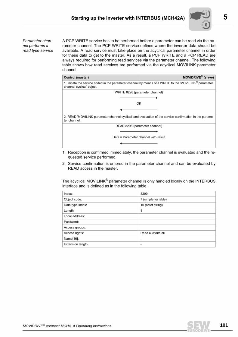
MOVIDRIVE® compact MCH4_A Operating Instructions 101
5Starting up the inverter with INTERBUS (MCH42A)
Parameter chan-
nel performs a
read type service
A PCP WRITE service has to be performed before a parameter can be read via the pa-
rameter channel. The PCP WRITE service defines where the inverter data should be
available. A read service must take place on the acyclical parameter channel in order
for these data to get to the master. As a result, a PCP WRITE and a PCP READ are
always required for performing read services via the parameter channel. The following
table shows how read services are performed via the acyclical MOVILINK parameter
channel.
1. Reception is confirmed immediately, the parameter channel is evaluated and the re-
quested service performed.
2. Service confirmation is entered in the parameter channel and can be evaluated by
READ access in the master.
The acyclical MOVILINK® parameter channel is only handled locally on the INTERBUS
interface and is defined as in the following table.
Control (master) MOVIDRIVE® (slave)
1. Initiate the service coded in the parameter channel by means of a WRITE to the 'MOVILINK® parameter channel cyclical' object.
WRITE 8298 (parameter channel)
OK
2. READ 'MOVILINK parameter channel cyclical' and evaluation of the service confirmation in the parame-ter channel.
READ 8298 (parameter channel)
Data = Parameter channel with result
Index: 8299
Object code: 7 (simple variable)
Data type index: 10 (octet string)
Length: 8
Local address:
Password:
Access groups:
Access rights: Read all/Write all
Name[16]: -
Extension length: -
00
I
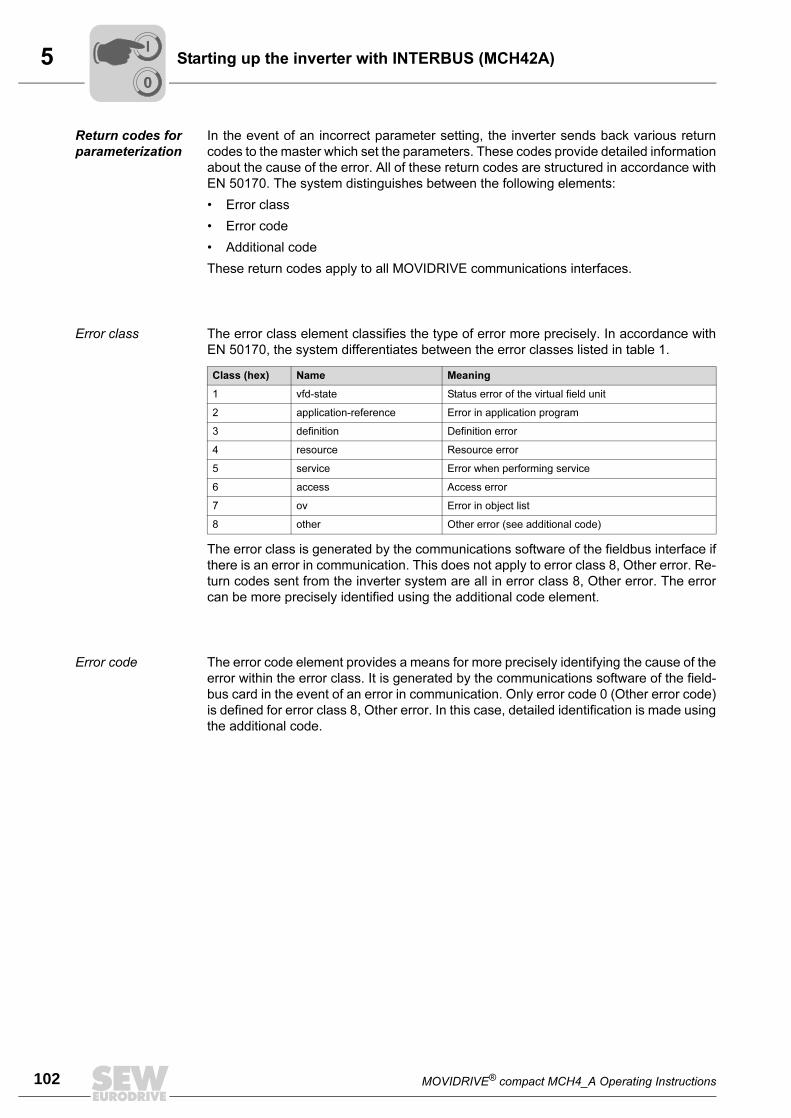
5
102 MOVIDRIVE® compact MCH4_A Operating Instructions
Starting up the inverter with INTERBUS (MCH42A)
Return codes for
parameterization
In the event of an incorrect parameter setting, the inverter sends back various return
codes to the master which set the parameters. These codes provide detailed information
about the cause of the error. All of these return codes are structured in accordance with
EN 50170. The system distinguishes between the following elements:
• Error class
• Error code
• Additional code
These return codes apply to all MOVIDRIVE communications interfaces.
Error class The error class element classifies the type of error more precisely. In accordance with
EN 50170, the system differentiates between the error classes listed in table 1.
The error class is generated by the communications software of the fieldbus interface if
there is an error in communication. This does not apply to error class 8, Other error. Re-
turn codes sent from the inverter system are all in error class 8, Other error. The error
can be more precisely identified using the additional code element.
Error code The error code element provides a means for more precisely identifying the cause of the
error within the error class. It is generated by the communications software of the field-
bus card in the event of an error in communication. Only error code 0 (Other error code)
is defined for error class 8, Other error. In this case, detailed identification is made using
the additional code.
Class (hex) Name Meaning
1 vfd-state Status error of the virtual field unit
2 application-reference Error in application program
3 definition Definition error
4 resource Resource error
5 service Error when performing service
6 access Access error
7 ov Error in object list
8 other Other error (see additional code)
00
I
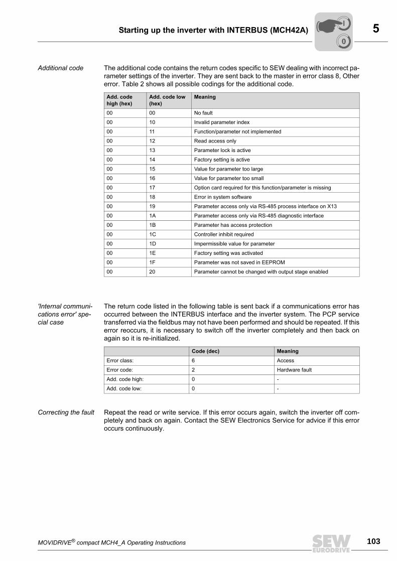
MOVIDRIVE® compact MCH4_A Operating Instructions 103
5Starting up the inverter with INTERBUS (MCH42A)
Additional code The additional code contains the return codes specific to SEW dealing with incorrect pa-
rameter settings of the inverter. They are sent back to the master in error class 8, Other
error. Table 2 shows all possible codings for the additional code.
'Internal communi-
cations error' spe-
cial case
The return code listed in the following table is sent back if a communications error has
occurred between the INTERBUS interface and the inverter system. The PCP service
transferred via the fieldbus may not have been performed and should be repeated. If this
error reoccurs, it is necessary to switch off the inverter completely and then back on
again so it is re-initialized.
Correcting the fault Repeat the read or write service. If this error occurs again, switch the inverter off com-
pletely and back on again. Contact the SEW Electronics Service for advice if this error
occurs continuously.
Add. code
high (hex)
Add. code low
(hex)
Meaning
00 00 No fault
00 10 Invalid parameter index
00 11 Function/parameter not implemented
00 12 Read access only
00 13 Parameter lock is active
00 14 Factory setting is active
00 15 Value for parameter too large
00 16 Value for parameter too small
00 17 Option card required for this function/parameter is missing
00 18 Error in system software
00 19 Parameter access only via RS-485 process interface on X13
00 1A Parameter access only via RS-485 diagnostic interface
00 1B Parameter has access protection
00 1C Controller inhibit required
00 1D Impermissible value for parameter
00 1E Factory setting was activated
00 1F Parameter was not saved in EEPROM
00 20 Parameter cannot be changed with output stage enabled
Code (dec) Meaning
Error class: 6 Access
Error code: 2 Hardware fault
Add. code high: 0 -
Add. code low: 0 -
00
I
5
104 MOVIDRIVE® compact MCH4_A Operating Instructions
Starting up the inverter with INTERBUS (MCH42A)
Control via pro-
cess data
The inverter is controlled using the process data simply by reading/writing the program
addresses where the INTERBUS process data of the inverter are replicated. The follow-
ing is an example for a simple STEP7 program for the Simatic S7:
L...W#16#0006
T...PAW...144... //Write 6hex on PO1 (control word = enable)
L...1500
T...PAW...146... //Write 1500dec on PO2 (speed setpoint = 300 rpm)
L...W#16#0000
T...PAW...148...//Write 0hex on PA3 (no function after factory setting)
Please refer to the Fieldbus Unit Profile manual for more information about controlling
the inverter via the process data channel, in particular regarding the coding of the control
and status word.
Setting parame-
ters via the PCP
interface
This chapter describes how parameters and IPOS variables can be read and written us-
ing the standardized INTERBUS PCP ‘Read' and 'Write' services. The example applies
to all 4th generation (G4) INTERBUS interface modules and is explained using PHOE-
NIX terminology.
The coding examples shown in the following chapters are shown in the same way as in
the 'Peripherals Communication Protocol (PCP)' INTERBUS user manual produced by
Phoenix Contact.
Prerequisite You should have the following user manuals:
• 'Peripherals Communication Protocol (PCP)' INTERBUS user manual, PHOENIX
CONTACT, IBS SYS PCP G4 UM
• MOVIDRIVE® Fieldbus Unit Profile manual
00
I
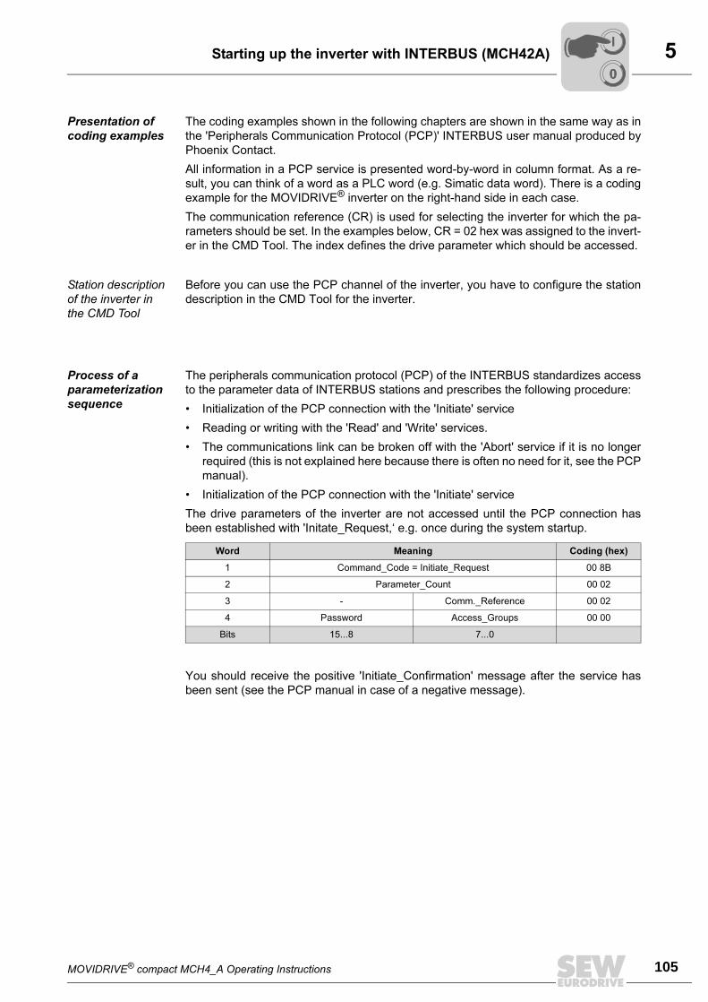
MOVIDRIVE® compact MCH4_A Operating Instructions 105
5Starting up the inverter with INTERBUS (MCH42A)
Presentation of
coding examples
The coding examples shown in the following chapters are shown in the same way as in
the 'Peripherals Communication Protocol (PCP)' INTERBUS user manual produced by
Phoenix Contact.
All information in a PCP service is presented word-by-word in column format. As a re-
sult, you can think of a word as a PLC word (e.g. Simatic data word). There is a coding
example for the MOVIDRIVE® inverter on the right-hand side in each case.
The communication reference (CR) is used for selecting the inverter for which the pa-
rameters should be set. In the examples below, CR = 02 hex was assigned to the invert-
er in the CMD Tool. The index defines the drive parameter which should be accessed.
Station description
of the inverter in
the CMD Tool
Before you can use the PCP channel of the inverter, you have to configure the station
description in the CMD Tool for the inverter.
Process of a
parameterization
sequence
The peripherals communication protocol (PCP) of the INTERBUS standardizes access
to the parameter data of INTERBUS stations and prescribes the following procedure:
• Initialization of the PCP connection with the 'Initiate' service
• Reading or writing with the 'Read' and 'Write' services.
• The communications link can be broken off with the 'Abort' service if it is no longer
required (this is not explained here because there is often no need for it, see the PCP
manual).
• Initialization of the PCP connection with the 'Initiate' service
The drive parameters of the inverter are not accessed until the PCP connection has
been established with 'Initate_Request,‘ e.g. once during the system startup.
You should receive the positive 'Initiate_Confirmation' message after the service has
been sent (see the PCP manual in case of a negative message).
Word Meaning Coding (hex)
1 Command_Code = Initiate_Request 00 8B
2 Parameter_Count 00 02
3 - Comm._Reference 00 02
4 Password Access_Groups 00 00
Bits 15...8 7...0
00
I
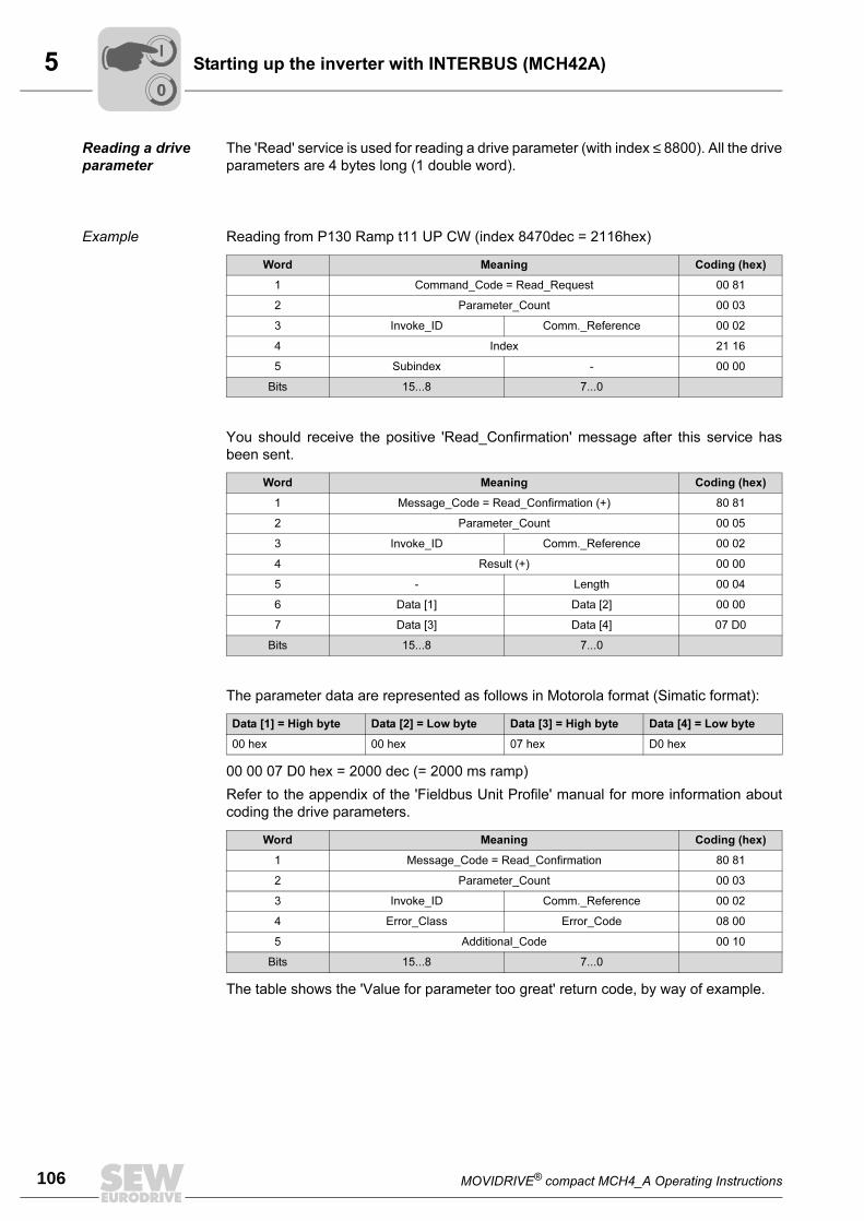
5
106 MOVIDRIVE® compact MCH4_A Operating Instructions
Starting up the inverter with INTERBUS (MCH42A)
Reading a drive
parameter
The 'Read' service is used for reading a drive parameter (with index ≤ 8800). All the drive
parameters are 4 bytes long (1 double word).
Example Reading from P130 Ramp t11 UP CW (index 8470dec = 2116hex)
You should receive the positive 'Read_Confirmation' message after this service has
been sent.
The parameter data are represented as follows in Motorola format (Simatic format):
00 00 07 D0 hex = 2000 dec (= 2000 ms ramp)
Refer to the appendix of the 'Fieldbus Unit Profile' manual for more information about
coding the drive parameters.
The table shows the 'Value for parameter too great' return code, by way of example.
Word Meaning Coding (hex)
1 Command_Code = Read_Request 00 81
2 Parameter_Count 00 03
3 Invoke_ID Comm._Reference 00 02
4 Index 21 16
5 Subindex - 00 00
Bits 15...8 7...0
Word Meaning Coding (hex)
1 Message_Code = Read_Confirmation (+) 80 81
2 Parameter_Count 00 05
3 Invoke_ID Comm._Reference 00 02
4 Result (+) 00 00
5 - Length 00 04
6 Data [1] Data [2] 00 00
7 Data [3] Data [4] 07 D0
Bits 15...8 7...0
Data [1] = High byte Data [2] = Low byte Data [3] = High byte Data [4] = Low byte
00 hex 00 hex 07 hex D0 hex
Word Meaning Coding (hex)
1 Message_Code = Read_Confirmation 80 81
2 Parameter_Count 00 03
3 Invoke_ID Comm._Reference 00 02
4 Error_Class Error_Code 08 00
5 Additional_Code 00 10
Bits 15...8 7...0
00
I
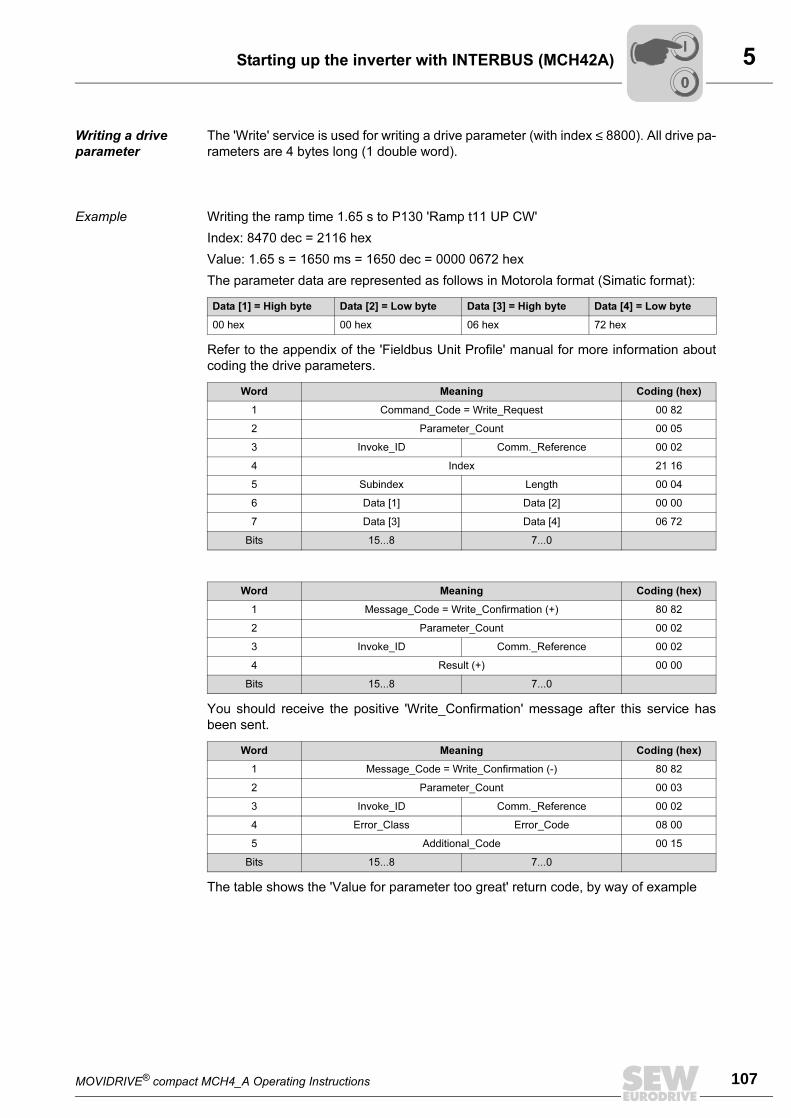
MOVIDRIVE® compact MCH4_A Operating Instructions 107
5Starting up the inverter with INTERBUS (MCH42A)
Writing a drive
parameter
The 'Write' service is used for writing a drive parameter (with index ≤ 8800). All drive pa-
rameters are 4 bytes long (1 double word).
Example Writing the ramp time 1.65 s to P130 'Ramp t11 UP CW'
Index: 8470 dec = 2116 hex
Value: 1.65 s = 1650 ms = 1650 dec = 0000 0672 hex
The parameter data are represented as follows in Motorola format (Simatic format):
Refer to the appendix of the 'Fieldbus Unit Profile' manual for more information about
coding the drive parameters.
You should receive the positive 'Write_Confirmation' message after this service has
been sent.
The table shows the 'Value for parameter too great' return code, by way of example
Data [1] = High byte Data [2] = Low byte Data [3] = High byte Data [4] = Low byte
00 hex 00 hex 06 hex 72 hex
Word Meaning Coding (hex)
1 Command_Code = Write_Request 00 82
2 Parameter_Count 00 05
3 Invoke_ID Comm._Reference 00 02
4 Index 21 16
5 Subindex Length 00 04
6 Data [1] Data [2] 00 00
7 Data [3] Data [4] 06 72
Bits 15...8 7...0
Word Meaning Coding (hex)
1 Message_Code = Write_Confirmation (+) 80 82
2 Parameter_Count 00 02
3 Invoke_ID Comm._Reference 00 02
4 Result (+) 00 00
Bits 15...8 7...0
Word Meaning Coding (hex)
1 Message_Code = Write_Confirmation (-) 80 82
2 Parameter_Count 00 03
3 Invoke_ID Comm._Reference 00 02
4 Error_Class Error_Code 08 00
5 Additional_Code 00 15
Bits 15...8 7...0
00
I
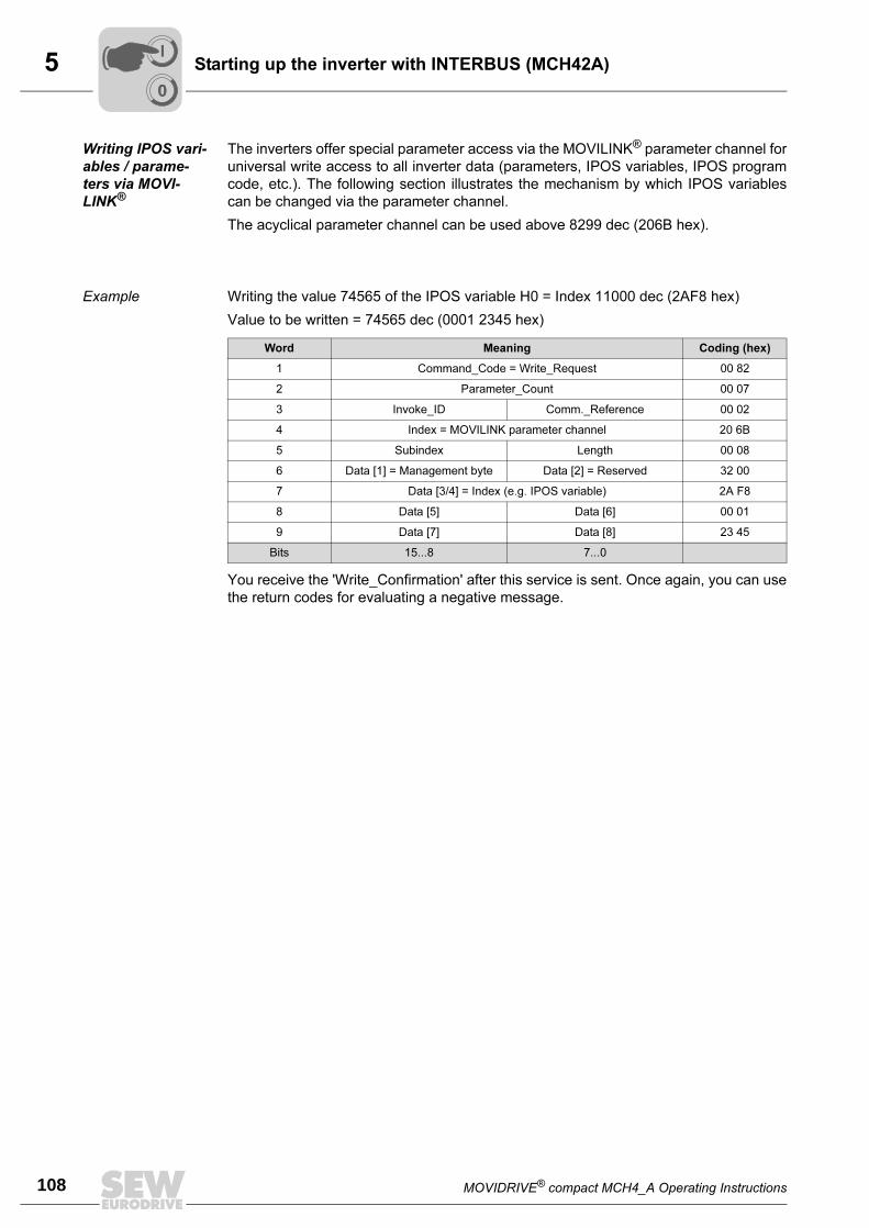
5
108 MOVIDRIVE® compact MCH4_A Operating Instructions
Starting up the inverter with INTERBUS (MCH42A)
Writing IPOS vari-
ables / parame-
ters via MOVI-
LINK®
The inverters offer special parameter access via the MOVILINK® parameter channel for
universal write access to all inverter data (parameters, IPOS variables, IPOS program
code, etc.). The following section illustrates the mechanism by which IPOS variables
can be changed via the parameter channel.
The acyclical parameter channel can be used above 8299 dec (206B hex).
Example Writing the value 74565 of the IPOS variable H0 = Index 11000 dec (2AF8 hex)
Value to be written = 74565 dec (0001 2345 hex)
You receive the 'Write_Confirmation' after this service is sent. Once again, you can use
the return codes for evaluating a negative message.
Word Meaning Coding (hex)
1 Command_Code = Write_Request 00 82
2 Parameter_Count 00 07
3 Invoke_ID Comm._Reference 00 02
4 Index = MOVILINK parameter channel 20 6B
5 Subindex Length 00 08
6 Data [1] = Management byte Data [2] = Reserved 32 00
7 Data [3/4] = Index (e.g. IPOS variable) 2A F8
8 Data [5] Data [6] 00 01
9 Data [7] Data [8] 23 45
Bits 15...8 7...0
00
I
MOVIDRIVE® compact MCH4_A Operating Instructions 109
5Starting up the inverter with INTERBUS (MCH42A)
Reading IPOS
variables / param-
eters via MOVI-
LINK®
The inverters offer special parameter access via the MOVILINK® parameter channel for
universal read access to all inverter data (parameters, IPOS variables, IPOS program
code, etc.). The following section illustrates the mechanism by which IPOS variables
can be read via the parameter channel. A two-stage procedure is required:
• Writing the MOVILINK parameter channel with the 'Read IPOS variable H0' job
• Reading the MOVILINK parameter channel
The MOVILINK parameter channel (acyclical) can be used above 8299 dec (206B hex).
Example Reading the IPOS variable H0 = Index 11000 dec (2AF8 hex)
Refer to the 'Fieldbus Unit Profile' manual for a detailed description of the MOVILINK
parameter channel.
Once the positive 'Write_Confirmation (+)' has been received, read access takes place
on the MOVILINK parameter channel; this involves reading the data into the interface
module which were read during the previous read job defined by 'Write_Request'.
Word Meaning Coding (hex)
1 Command_Code = Write_Request 00 82
2 Parameter_Count 00 07
3 Invoke_ID Comm._Reference 00 02
4 Index = MOVILINK parameter channel 20 6B
5 Subindex Length 00 08
6 Data [1] = Management byte Data [2] = Reserved 31 00
7 Data [3/4] = Index (e.g. IPOS variable) 2A F8
8 Data [5] Data [6] 00 00
9 Data [7] Data [8] 00 00
Bits 15...8 7...0
Word Meaning Coding (hex)
1 Command_Code = Read_Request 00 81
2 Parameter_Count 00 03
3 Invoke_ID Comm._Reference 00 02
4 Index = MOVILINK parameter channel 20 6B
5 Subindex - 00 00
Bits 15...8 7...0
00
I
5
110 MOVIDRIVE® compact MCH4_A Operating Instructions
Starting up the inverter with INTERBUS (MCH42A)
You should receive the positive 'Read_Confirmation' message after this service has
been sent.
You can use the return codes for evaluating a negative message.
Word Meaning Coding (hex)
1 Message_Code = Read_Confirmation (+) 80 81
2 Parameter_Count 00 07
3 Invoke_ID Comm._Reference 00 02
4 Result (+) 00 00
5 - Length 00 08
6 Data [1] = Management byte Data [2] = Reserved 31 00
7 Data [3/4] = Index (e.g. IPOS variable) 2A F8
8 Data [5] Data [6] 00 01
9 Data [7] Data [8] 23 45
Bits 15...8 7...0
Word Meaning Coding (hex)
1 Message_Code = Read_Confirmation 80 81
2 Parameter_Count 00 03
3 Invoke_ID Comm._Reference 00 02
4 Error_Class Error_Code 08 00
5 Additional_Code 00 10
Bits 15...8 7...0
00
I
MOVIDRIVE® compact MCH4_A Operating Instructions 111
5Starting up the inverter with INTERBUS (MCH42A)
Writing IPOS vari-
ables / parame-
ters using the
download param-
eter block
MOVIDRIVE® inverters let you download the parameter block to write several IPOS vari-
ables and parameters at the same time using one PCP service.
The download parameter block is always 230 bytes long. It is possible to write up to 42
drive parameters and IPOS variables in one block.
Example Three values of the inverter are to be written with one 'Write_Request':
You receive the 'Write_Confirmation' after this service is sent. Once again, you can use
the return codes for evaluating a negative message. The individual parameters of the
download parameter block in the inverter are written one after the other. This means if
there is a negative 'Write_Confirmation' in the high part of the additional code, the pa-
rameter number at which the error occurred is entered.
Parameter/variable name Index Value to be written
IPOS variable H0 11000 dec (2AF8 hex) 1 dec (1 hex)
IPOS variable H1 11001 dec (2AF9 hex) -40000 dec (FFFF63C0 hex)
P130 Ramp t11 UP CW 8470 dec (2116 hex) 1500 dec (05DC hex)
Word Meaning Coding (hex)
1 Command_Code = Write_Request 00 82
2 Parameter_Count = 118 words (= 76 hex) 00 76
3 Invoke_ID Comm._Reference 00 02
4 Index = Download parameter block 20 68
5 Subindex Length = 230 bytes (= E6 hex) 00 E6
6 Data [1] = Reserved Data [2] = Number of parame-ters
00 03
7 Data [3/4] = Index of the 1st parameter (e.g. IPOS variable H0) 2A F8
8 Data [5] Data [6] 00 00
9 Data [7] Data [8] 00 01
10 Data [9/10] = Index of the 1st parameter (e.g. IPOS variable H1) 2A F9
11 Data [11] Data [12] FF FF
12 Data [13] Data [14] 63 C0
13 Data [15/16] = Index of the 1st parameter (P130 Ramp t11) 21 16
14 Data [17] Data [18] 00 00
15 Data [19] Data [20] 05 DC
... ... ... ...
Bits 15...8 7...0
00
I
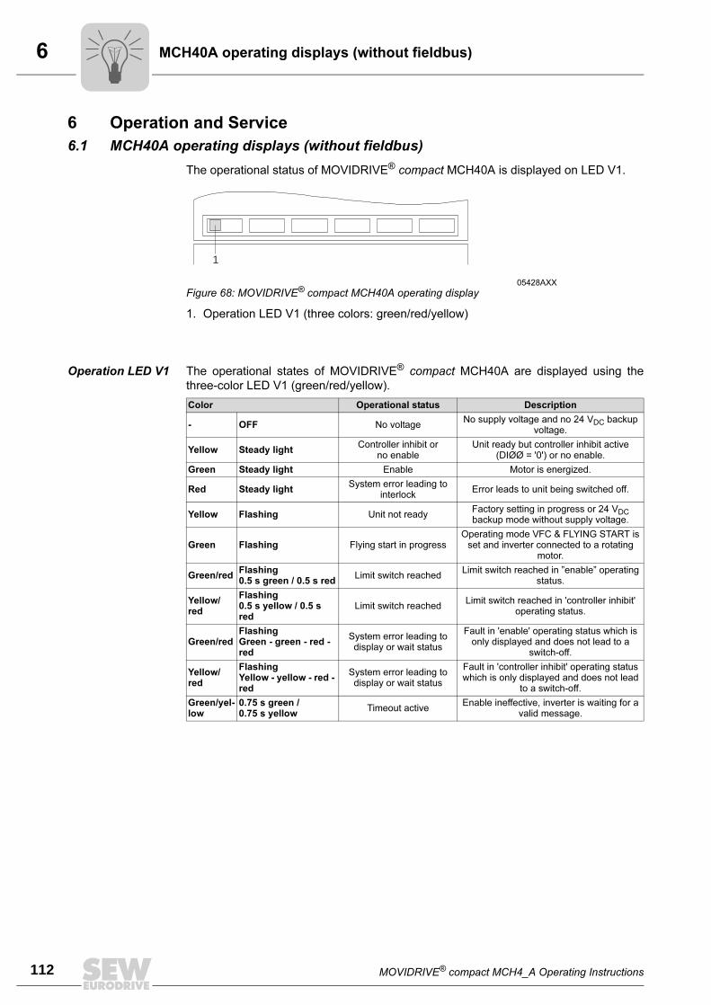
6
112 MOVIDRIVE® compact MCH4_A Operating Instructions
MCH40A operating displays (without fieldbus)
6 Operation and Service
6.1 MCH40A operating displays (without fieldbus)
The operational status of MOVIDRIVE® compact MCH40A is displayed on LED V1.
1. Operation LED V1 (three colors: green/red/yellow)
Operation LED V1 The operational states of MOVIDRIVE® compact MCH40A are displayed using the
three-color LED V1 (green/red/yellow).
05428AXX
Figure 68: MOVIDRIVE® compact MCH40A operating display
1
Color Operational status Description
- OFF No voltageNo supply voltage and no 24 VDC backup
voltage.
Yellow Steady lightController inhibit or
no enableUnit ready but controller inhibit active
(DIØØ = '0') or no enable.
Green Steady light Enable Motor is energized.
Red Steady lightSystem error leading to
interlockError leads to unit being switched off.
Yellow Flashing Unit not readyFactory setting in progress or 24 VDC backup mode without supply voltage.
Green Flashing Flying start in progressOperating mode VFC & FLYING START is
set and inverter connected to a rotating motor.
Green/redFlashing0.5 s green / 0.5 s red
Limit switch reachedLimit switch reached in ”enable” operating
status.
Yellow/red
Flashing0.5 s yellow / 0.5 s red
Limit switch reachedLimit switch reached in 'controller inhibit'
operating status.
Green/redFlashingGreen - green - red - red
System error leading to display or wait status
Fault in 'enable' operating status which is only displayed and does not lead to a
switch-off.
Yellow/red
FlashingYellow - yellow - red - red
System error leading to display or wait status
Fault in 'controller inhibit' operating status which is only displayed and does not lead
to a switch-off.
Green/yel-low
0.75 s green /0.75 s yellow
Timeout activeEnable ineffective, inverter is waiting for a
valid message.
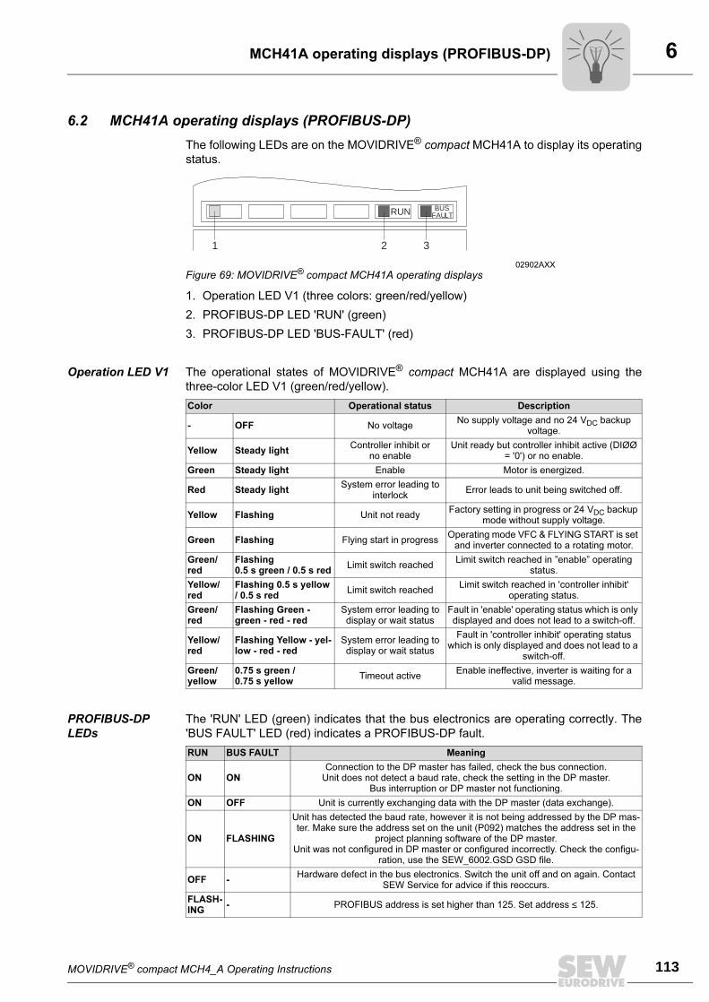
MOVIDRIVE® compact MCH4_A Operating Instructions 113
6MCH41A operating displays (PROFIBUS-DP)
6.2 MCH41A operating displays (PROFIBUS-DP)
The following LEDs are on the MOVIDRIVE® compact MCH41A to display its operating
status.
1. Operation LED V1 (three colors: green/red/yellow)
2. PROFIBUS-DP LED 'RUN' (green)
3. PROFIBUS-DP LED 'BUS-FAULT' (red)
Operation LED V1 The operational states of MOVIDRIVE® compact MCH41A are displayed using the
three-color LED V1 (green/red/yellow).
PROFIBUS-DP
LEDs
The 'RUN' LED (green) indicates that the bus electronics are operating correctly. The
'BUS FAULT' LED (red) indicates a PROFIBUS-DP fault.
02902AXX
Figure 69: MOVIDRIVE® compact MCH41A operating displays
RUN BUSFAULT
1 2 3
Color Operational status Description
- OFF No voltageNo supply voltage and no 24 VDC backup
voltage.
Yellow Steady lightController inhibit or
no enableUnit ready but controller inhibit active (DIØØ
= '0') or no enable.
Green Steady light Enable Motor is energized.
Red Steady lightSystem error leading to
interlockError leads to unit being switched off.
Yellow Flashing Unit not readyFactory setting in progress or 24 VDC backup
mode without supply voltage.
Green Flashing Flying start in progressOperating mode VFC & FLYING START is set
and inverter connected to a rotating motor.
Green/red
Flashing0.5 s green / 0.5 s red
Limit switch reachedLimit switch reached in ”enable” operating
status.
Yellow/red
Flashing 0.5 s yellow / 0.5 s red
Limit switch reachedLimit switch reached in 'controller inhibit'
operating status.
Green/red
Flashing Green - green - red - red
System error leading to display or wait status
Fault in 'enable' operating status which is only displayed and does not lead to a switch-off.
Yellow/red
Flashing Yellow - yel-low - red - red
System error leading to display or wait status
Fault in 'controller inhibit' operating status which is only displayed and does not lead to a
switch-off.
Green/yellow
0.75 s green /0.75 s yellow
Timeout activeEnable ineffective, inverter is waiting for a
valid message.
RUN BUS FAULT Meaning
ON ONConnection to the DP master has failed, check the bus connection.
Unit does not detect a baud rate, check the setting in the DP master.Bus interruption or DP master not functioning.
ON OFF Unit is currently exchanging data with the DP master (data exchange).
ON FLASHING
Unit has detected the baud rate, however it is not being addressed by the DP mas-ter. Make sure the address set on the unit (P092) matches the address set in the
project planning software of the DP master.Unit was not configured in DP master or configured incorrectly. Check the configu-
ration, use the SEW_6002.GSD GSD file.
OFF -Hardware defect in the bus electronics. Switch the unit off and on again. Contact
SEW Service for advice if this reoccurs.
FLASH-ING
- PROFIBUS address is set higher than 125. Set address ≤ 125.
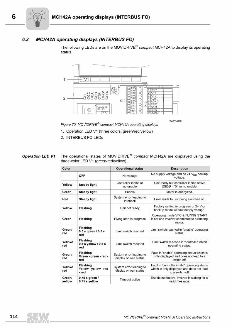
6
114 MOVIDRIVE® compact MCH4_A Operating Instructions
MCH42A operating displays (INTERBUS FO)
6.3 MCH42A operating displays (INTERBUS FO)
The following LEDs are on the MOVIDRIVE® compact MCH42A to display its operating
status.
1. Operation LED V1 (three colors: green/red/yellow)
2. INTERBUS FO LEDs
Operation LED V1 The operational states of MOVIDRIVE® compact MCH42A are displayed using the
three-color LED V1 (green/red/yellow).
05225AXX
Figure 70: MOVIDRIVE® compact MCH42A operating displays
V1
X10
123456789
1011
U CC
BA
RD
TR
FO
1F
O2
L
123456789
REF1AI11AI12AI21AGNDREF2SC11SC12DGND
Remote INX30 IN
X1
0
1.
2.
Color Operational status Description
- OFF No voltageNo supply voltage and no 24 VDC backup
voltage.
Yellow Steady lightController inhibit or
no enableUnit ready but controller inhibit active
(DIØØ = '0') or no enable.
Green Steady light Enable Motor is energized.
Red Steady lightSystem error leading to
interlockError leads to unit being switched off.
Yellow Flashing Unit not readyFactory setting in progress or 24 VDC backup mode without supply voltage.
Green Flashing Flying start in progressOperating mode VFC & FLYING START
is set and inverter connected to a rotating motor.
Green/red
Flashing0.5 s green / 0.5 s red
Limit switch reachedLimit switch reached in ”enable” operating
status.
Yellow/red
Flashing0.5 s yellow / 0.5 s red
Limit switch reachedLimit switch reached in 'controller inhibit'
operating status.
Green/red
FlashingGreen - green - red - red
System error leading to display or wait status
Fault in 'enable' operating status which is only displayed and does not lead to a
switch-off.
Yellow/red
FlashingYellow - yellow - red - red
System error leading to display or wait status
Fault in 'controller inhibit' operating status which is only displayed and does not lead
to a switch-off.
Green/yellow
0.75 s green /0.75 s yellow
Timeout activeEnable ineffective, inverter is waiting for a
valid message.
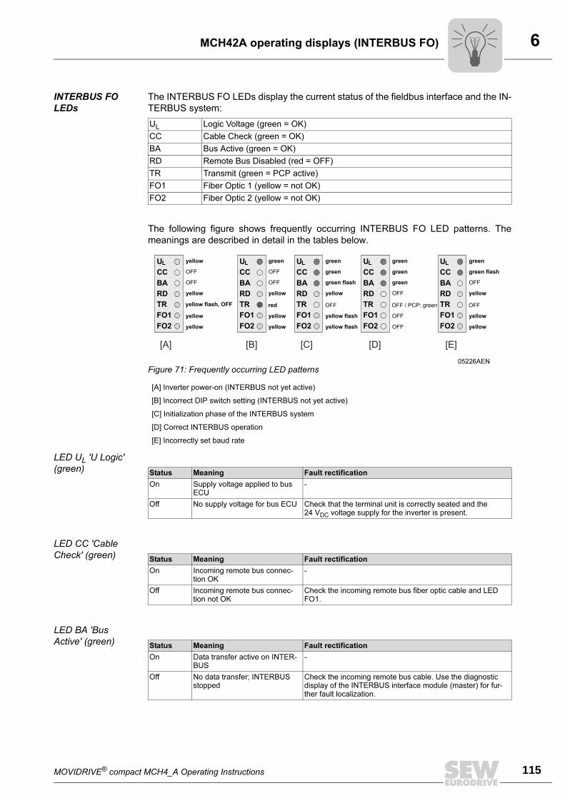
MOVIDRIVE® compact MCH4_A Operating Instructions 115
6MCH42A operating displays (INTERBUS FO)
INTERBUS FO
LEDs
The INTERBUS FO LEDs display the current status of the fieldbus interface and the IN-
TERBUS system:
The following figure shows frequently occurring INTERBUS FO LED patterns. The
meanings are described in detail in the tables below.
LED UL 'U Logic'
(green)
LED CC 'Cable
Check' (green)
LED BA 'Bus
Active' (green)
UL Logic Voltage (green = OK)
CC Cable Check (green = OK)
BA Bus Active (green = OK)
RD Remote Bus Disabled (red = OFF)
TR Transmit (green = PCP active)
FO1 Fiber Optic 1 (yellow = not OK)
FO2 Fiber Optic 2 (yellow = not OK)
05226AEN
Figure 71: Frequently occurring LED patterns
[A] Inverter power-on (INTERBUS not yet active)
[B] Incorrect DIP switch setting (INTERBUS not yet active)
[C] Initialization phase of the INTERBUS system
[D] Correct INTERBUS operation
[E] Incorrectly set baud rate
Status Meaning Fault rectification
On Supply voltage applied to bus ECU
-
Off No supply voltage for bus ECU Check that the terminal unit is correctly seated and the 24 VDC voltage supply for the inverter is present.
Status Meaning Fault rectification
On Incoming remote bus connec-tion OK
-
Off Incoming remote bus connec-tion not OK
Check the incoming remote bus fiber optic cable and LED FO1.
Status Meaning Fault rectification
On Data transfer active on INTER-BUS
-
Off No data transfer; INTERBUS stopped
Check the incoming remote bus cable. Use the diagnostic display of the INTERBUS interface module (master) for fur-ther fault localization.
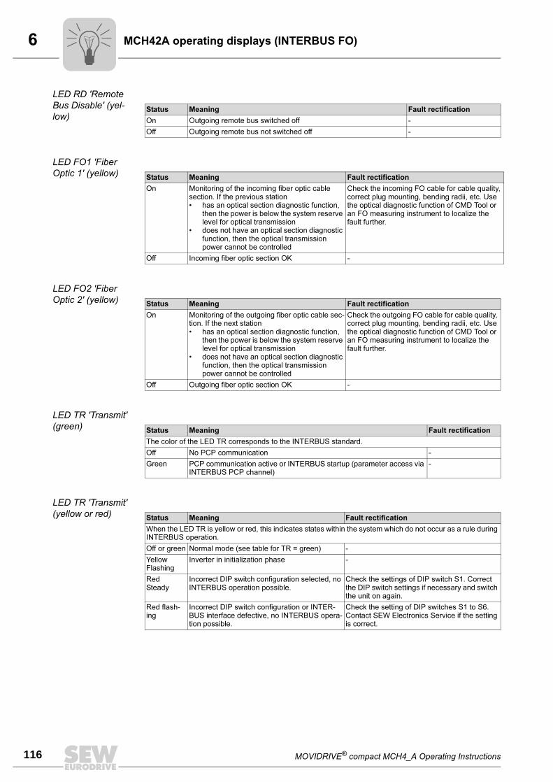
6
116 MOVIDRIVE® compact MCH4_A Operating Instructions
MCH42A operating displays (INTERBUS FO)
LED RD 'Remote
Bus Disable' (yel-
low)
LED FO1 'Fiber
Optic 1' (yellow)
LED FO2 'Fiber
Optic 2' (yellow)
LED TR 'Transmit'
(green)
LED TR 'Transmit'
(yellow or red)
Status Meaning Fault rectification
On Outgoing remote bus switched off -
Off Outgoing remote bus not switched off -
Status Meaning Fault rectification
On Monitoring of the incoming fiber optic cable section. If the previous station• has an optical section diagnostic function,
then the power is below the system reserve level for optical transmission
• does not have an optical section diagnostic function, then the optical transmission power cannot be controlled
Check the incoming FO cable for cable quality, correct plug mounting, bending radii, etc. Use the optical diagnostic function of CMD Tool or an FO measuring instrument to localize the fault further.
Off Incoming fiber optic section OK -
Status Meaning Fault rectification
On Monitoring of the outgoing fiber optic cable sec-tion. If the next station• has an optical section diagnostic function,
then the power is below the system reserve level for optical transmission
• does not have an optical section diagnostic function, then the optical transmission power cannot be controlled
Check the outgoing FO cable for cable quality, correct plug mounting, bending radii, etc. Use the optical diagnostic function of CMD Tool or an FO measuring instrument to localize the fault further.
Off Outgoing fiber optic section OK -
Status Meaning Fault rectification
The color of the LED TR corresponds to the INTERBUS standard.
Off No PCP communication -
Green PCP communication active or INTERBUS startup (parameter access via INTERBUS PCP channel)
-
Status Meaning Fault rectification
When the LED TR is yellow or red, this indicates states within the system which do not occur as a rule during INTERBUS operation.
Off or green Normal mode (see table for TR = green) -
YellowFlashing
Inverter in initialization phase -
RedSteady
Incorrect DIP switch configuration selected, no INTERBUS operation possible.
Check the settings of DIP switch S1. Correct the DIP switch settings if necessary and switch the unit on again.
Red flash-ing
Incorrect DIP switch configuration or INTER-BUS interface defective, no INTERBUS opera-tion possible.
Check the setting of DIP switches S1 to S6. Contact SEW Electronics Service if the setting is correct.
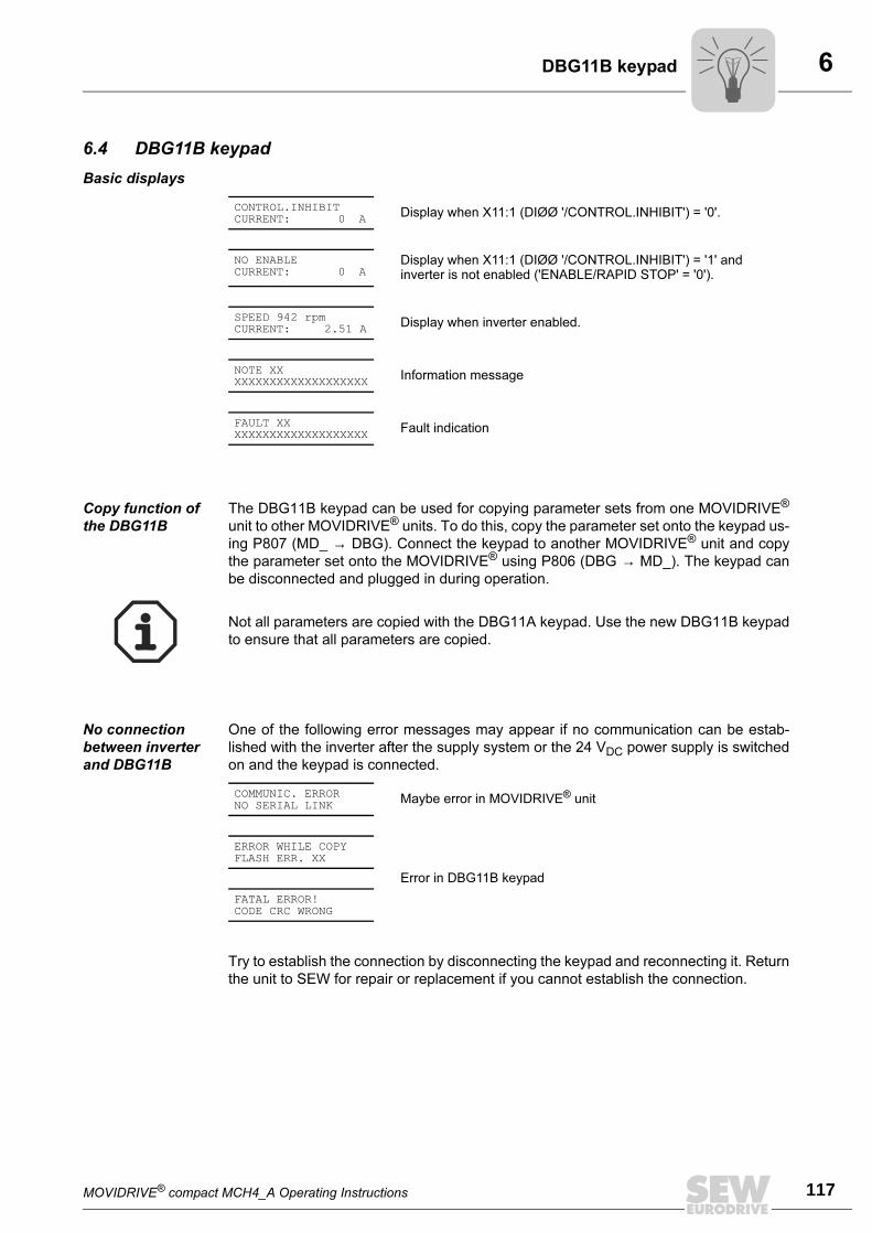
MOVIDRIVE® compact MCH4_A Operating Instructions 117
6DBG11B keypad
6.4 DBG11B keypad
Basic displays
Copy function of
the DBG11B
The DBG11B keypad can be used for copying parameter sets from one MOVIDRIVE®
unit to other MOVIDRIVE® units. To do this, copy the parameter set onto the keypad us-
ing P807 (MD_ → DBG). Connect the keypad to another MOVIDRIVE® unit and copy
the parameter set onto the MOVIDRIVE® using P806 (DBG → MD_). The keypad can
be disconnected and plugged in during operation.
No connection
between inverter
and DBG11B
One of the following error messages may appear if no communication can be estab-
lished with the inverter after the supply system or the 24 VDC power supply is switched
on and the keypad is connected.
Try to establish the connection by disconnecting the keypad and reconnecting it. Return
the unit to SEW for repair or replacement if you cannot establish the connection.
CONTROL.INHIBITCURRENT: 0 A
Display when X11:1 (DIØØ '/CONTROL.INHIBIT') = '0'.
NO ENABLECURRENT: 0 A
Display when X11:1 (DIØØ '/CONTROL.INHIBIT') = '1' and inverter is not enabled ('ENABLE/RAPID STOP' = '0').
SPEED 942 rpmCURRENT: 2.51 A
Display when inverter enabled.
NOTE XXXXXXXXXXXXXXXXXXXXX
Information message
FAULT XXXXXXXXXXXXXXXXXXXXX
Fault indication
Not all parameters are copied with the DBG11A keypad. Use the new DBG11B keypad
to ensure that all parameters are copied.
COMMUNIC. ERRORNO SERIAL LINK
Maybe error in MOVIDRIVE® unit
ERROR WHILE COPYFLASH ERR. XX
Error in DBG11B keypad
FATAL ERROR!CODE CRC WRONG
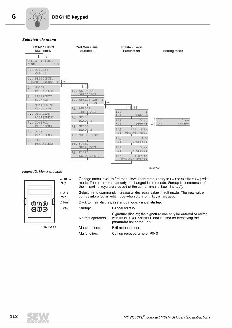
6
118 MOVIDRIVE® compact MCH4_A Operating Instructions
DBG11B keypad
Selected via menu
02407AEN
Figure 72: Menu structure
01406AXX
← or → key
Change menu level, in 3rd menu level (parameter) entry to (→) or exit from (←) edit mode. The parameter can only be changed in edit mode. Startup is commenced if the ← and → keys are pressed at the same time (→ Sec. 'Startup').
↑ or ↓ key
Select menu command, increase or decrease value in edit mode. The new value comes into effect in edit mode when the ↑ or ↓ key is released.
Q key Back to main display; in startup mode, cancel startup.
E key Startup: Cancel startup
Normal operation:Signature display; the signature can only be entered or edited with MOVITOOLS/SHELL and is used for identifying the parameter set or the unit.
Manual mode: Exit manual mode
Malfunction: Call up reset parameter P840
[ ]↑
[ ]↑
[ ]↑
[ ]↓
[ ]↓
[ ]↓
[ ]←
[ ]←
[ ]←
[ ]→
[ ]→
[ ]→
1st Menu levelMain menu
2nd Menu levelSubmenu
3rd Menu levelParameters Editing mode
11 1A11 SCALING0
11 REF. NMAXA11 OPERAT. MODE2
11 0 VA11 V-OFFSET3
11 0 /MA11 n-OFFSET4
11 1.89 msETPOINT FILTER5
11 0 mVA11 OFFSET1 111 mV
A11 OFFSET0
0.. DISPLAYVALUES
CONTR. INHIBITCURR.: 0 A
1 . SETPOINTSELECTION
0
1.. SETPOINTS/RAMP GENERATORS
1 . ANALOG INP. 1(+/- 10 V)
1
1 . ANALOGINPUT AI2
2
3.. MOTORPARAMETERS
1 . SPEEDRAMPS 1
3
4.. REFERENCESIGNALS
1 . SPEEDRAMPS 2
4
5.. MONITORINGFUNCTIONS
1 . MOTOR. POT.5
6.. TERMINALASSIGNMENT
1 . FIXEDSETPOINTS 1
6
7.. CONTROLFUNCTIONS
1 . FIXEDSETPOINTS 2
7
8.. UNITFUNCTIONS
9.. IPOSPARAMETERS
E Q
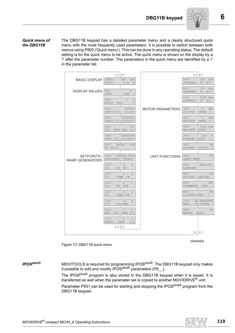
MOVIDRIVE® compact MCH4_A Operating Instructions 119
6DBG11B keypad
Quick menu of
the DBG11B
The DBG11B keypad has a detailed parameter menu and a clearly structured quick
menu with the most frequently used parameters. It is possible to switch between both
menus using P800 ('Quick menu'). This can be done in any operating status. The default
setting is for the quick menu to be active. The quick menu is shown on the display by a
'/' after the parameter number. The parameters in the quick menu are identified by a '/'
in the parameter list.
IPOSplus® MOVITOOLS is required for programming IPOSplus®. The DBG11B keypad only makes
it possible to edit and modify IPOSplus® parameters (P9__).
The IPOSplus® program is also stored in the DBG11B keypad when it is saved. It is
transferred as well when the parameter set is copied to another MOVIDRIVE® unit.
Parameter P931 can be used for starting and stopping the IPOSplus® program from the
DBG11B keypad.
02408AEN
Figure 73: DBG11B quick menu
[ ]↓ [ ]↓
[ ]↓
[ ]↓
[ ]↑ [ ]↑
[ ]↑
[ ]↑
SETPOINTS /RAMP GENERATORS
DISPLAY VALUES
MOTOR PARAMETERS
UNIT FUNCTIONS
BASIC DISPLAY
001/ 0USER [rpm ]
SPEED: 942 rpmCURR.: 2.51 A
006/ 0 %MOTOR UTIL. 1
036/ 000000INPUT DIO: 012345
048/ 00000000INPUT DI1:01234567
053/ 001OUT. TERM.DOØ: 012
068/ 00000000OUTP. D1: 01234567
080/ FAULT t-ØNO FAULT
100/ UNIPOL./FIXSETPOINTS SOURCE
130/ 2 sT11 UP CW
131/ 2 sT11 DOWN CW
132/ 2 sT11 UP CCW
133/ 2 sT11 DOWN CCW
134/ 10 sT12 UP=DOWN
136/ 2 sRAP. STP. RAMP T13
137/ 2 sEMERG. RAMP T14
160/ 150 rpmINTERNAL SP N11
161/ 750 rpmINTERNAL SP N12
162/ 1500 rpmINTERNAL SP N13
300/ 0 rpmST/STOP SPEED 1
301/ 0 rpmMINIMUM SPEED 1
302/ 1500 rpmMAXIMUM SPEED 1
303/ 150 %CURRENT LIMIT 1
320/ ONAUTOMAT. ADJUST. 1
800/ ONSHORT MENU
801/ ENGLISHLANGUAGE
802/ NOFACTORY SETTING
803/ OFFPARAMETER LOCK
820/ ON4-QUADR-OPER. 1
835/ NO RESPONSERESP. TF-SIGNAL
840/ NOMANUAL RESET
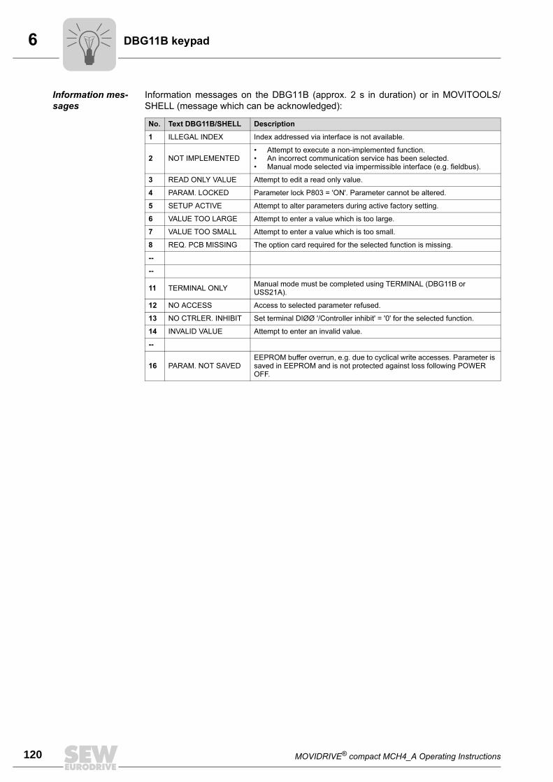
6
120 MOVIDRIVE® compact MCH4_A Operating Instructions
DBG11B keypad
Information mes-
sages
Information messages on the DBG11B (approx. 2 s in duration) or in MOVITOOLS/
SHELL (message which can be acknowledged):
No. Text DBG11B/SHELL Description
1 ILLEGAL INDEX Index addressed via interface is not available.
2 NOT IMPLEMENTED• Attempt to execute a non-implemented function.• An incorrect communication service has been selected.• Manual mode selected via impermissible interface (e.g. fieldbus).
3 READ ONLY VALUE Attempt to edit a read only value.
4 PARAM. LOCKED Parameter lock P803 = 'ON'. Parameter cannot be altered.
5 SETUP ACTIVE Attempt to alter parameters during active factory setting.
6 VALUE TOO LARGE Attempt to enter a value which is too large.
7 VALUE TOO SMALL Attempt to enter a value which is too small.
8 REQ. PCB MISSING The option card required for the selected function is missing.
--
--
11 TERMINAL ONLYManual mode must be completed using TERMINAL (DBG11B or USS21A).
12 NO ACCESS Access to selected parameter refused.
13 NO CTRLER. INHIBIT Set terminal DIØØ '/Controller inhibit' = '0' for the selected function.
14 INVALID VALUE Attempt to enter an invalid value.
--
16 PARAM. NOT SAVEDEEPROM buffer overrun, e.g. due to cyclical write accesses. Parameter is saved in EEPROM and is not protected against loss following POWER OFF.
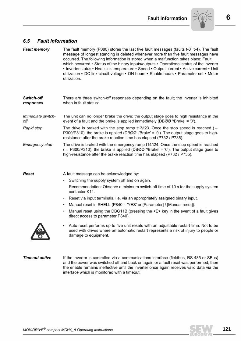
MOVIDRIVE® compact MCH4_A Operating Instructions 121
6Fault information
6.5 Fault information
Fault memory The fault memory (P080) stores the last five fault messages (faults t-0 t-4). The fault
message of longest standing is deleted whenever more than five fault messages have
occurred. The following information is stored when a malfunction takes place: Fault
which occurred • Status of the binary inputs/outputs • Operational status of the inverter
• Inverter status • Heat sink temperature • Speed • Output current • Active current • Unit
utilization • DC link circuit voltage • ON hours • Enable hours • Parameter set • Motor
utilization.
Switch-off
responses
There are three switch-off responses depending on the fault; the inverter is inhibited
when in fault status:
Immediate switch-
off
The unit can no longer brake the drive; the output stage goes to high resistance in the
event of a fault and the brake is applied immediately (DBØØ '/Brake' = '0').
Rapid stop The drive is braked with the stop ramp t13/t23. Once the stop speed is reached (→P300/P310), the brake is applied (DBØØ '/Brake' = '0'). The output stage goes to high-
resistance after the brake reaction time has elapsed (P732 / P735).
Emergency stop The drive is braked with the emergency ramp t14/t24. Once the stop speed is reached
(→ P300/P310), the brake is applied (DBØØ '/Brake' = '0'). The output stage goes to
high-resistance after the brake reaction time has elapsed (P732 / P735).
Reset A fault message can be acknowledged by:
• Switching the supply system off and on again.
Recommendation: Observe a minimum switch-off time of 10 s for the supply system
contactor K11.
• Reset via input terminals, i.e. via an appropriately assigned binary input.
• Manual reset in SHELL (P840 = 'YES' or [Parameter] / [Manual reset]).
• Manual reset using the DBG11B (pressing the <E> key in the event of a fault gives
direct access to parameter P840).
Timeout active If the inverter is controlled via a communications interface (fieldbus, RS-485 or SBus)
and the power was switched off and back on again or a fault reset was performed, then
the enable remains ineffective until the inverter once again receives valid data via the
interface which is monitored with a timeout.
• Auto reset performs up to five unit resets with an adjustable restart time. Not to be
used with drives where an automatic restart represents a risk of injury to people or
damage to equipment.
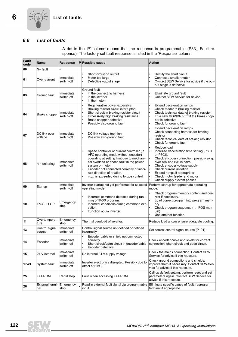
6
122 MOVIDRIVE® compact MCH4_A Operating Instructions
List of faults
6.6 List of faults
A dot in the 'P' column means that the response is programmable (P83_ Fault re-
sponse). The factory set fault response is listed in the 'Response' column.
Fault code
Name Response P Possible cause Action
00 No fault -
01 Over-currentImmediate switch-off
• Short circuit on output• Motor too large• Defective output stage
• Rectify the short circuit• Connect a smaller motor• Contact SEW Service for advice if the out-
put stage is defective
03 Ground faultImmediate switch-off
Ground fault• in the connecting harness• in the inverter• in the motor
• Eliminate ground fault• Contact SEW Service for advice
04 Brake chopperImmediate switch-off
• Regenerative power excessive• Braking resistor circuit interrupted• Short circuit in braking resistor circuit• Excessively high braking resistance• Brake chopper defective• Possibly also ground fault
• Extend deceleration ramps• Check feeder to braking resistor• Check technical data of braking resistor• Fit a new MOVIDRIVE® if the brake chop-
per is defective• Check for ground fault
07DC link over-voltage
Immediate switch-off
• DC link voltage too high• Possibly also ground fault
• Extend deceleration ramps• Check connecting harness for braking
resistor• Check technical data of braking resistor• Check for ground fault
08 n-monitoringImmediate switch-off
• Speed controller or current controller (in VFC operating mode without encoder) operating at setting limit due to mechani-cal overload or phase fault in the power system or motor.
• Encoder not connected correctly or incor-rect direction of rotation.
• nmax is exceeded during torque control.
• Reduce load• Increase deceleration time setting (P501
or P503).• Check encoder connection, possibly swap
over A/A and B/B in pairs• Check encoder voltage supply• Check current limitation• Extend ramps if appropriate• Check motor feeder and motor• Check supply system phases
09 StartupImmediate switch-off
Inverter startup not yet performed for selected operating mode.
Perform startup for appropriate operating mode.
10 IPOS-ILLOPEmergency stop
• Incorrect command detected during run-ning of IPOS program.
• Incorrect conditions during command exe-cution.
• Function not in inverter.
• Check program memory content and cor-rect if necessary.
• Load correct program into program mem-ory.
• Check program sequence (→ IPOS man-ual)
• Use another function.
11Overtempera-ture
Emergency stop
Thermal overload of inverter. Reduce load and/or ensure adequate cooling.
13Control signal source
Immediate switch-off
Control signal source not defined or defined incorrectly.
Set correct control signal source (P101).
14 EncoderImmediate switch-off
• Encoder cable or shield not connected correctly
• Short circuit/open circuit in encoder cable• Encoder defective
Check encoder cable and shield for correct connection, short circuit and open circuit.
15 24 V internalImmediate switch-off
No internal 24 V supply voltage.Check the mains connection. Contact SEW Service for advice if this reoccurs.
17-24 System faultImmediate switch-off
Inverter electronics disrupted. Possibly due to effect of EMC.
Check ground connections and shields; improve them if necessary. Contact SEW Ser-vice for advice if this reoccurs.
25 EEPROM Rapid stop Fault when accessing EEPROMCall up default setting, perform reset and set parameters again. Contact SEW Service for advice if this reoccurs.
26External termi-nal
Emergency stop
• Read in external fault signal via programmable input.
Eliminate specific cause of fault; reprogram terminal if appropriate.
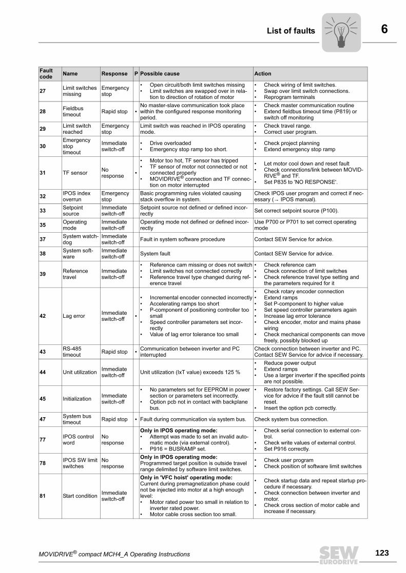
MOVIDRIVE® compact MCH4_A Operating Instructions 123
6List of faults
27Limit switches missing
Emergency stop
• Open circuit/both limit switches missing• Limit switches are swapped over in rela-
tion to direction of rotation of motor
• Check wiring of limit switches.• Swap over limit switch connections.• Reprogram terminals
28Fieldbustimeout
Rapid stop •No master-slave communication took place within the configured response monitoring period.
• Check master communication routine• Extend fieldbus timeout time (P819) or
switch off monitoring
29Limit switch reached
Emergency stop
Limit switch was reached in IPOS operating mode.
• Check travel range.• Correct user program.
30Emergency stoptimeout
Immediate switch-off
• Drive overloaded• Emergency stop ramp too short.
• Check project planning• Extend emergency stop ramp
31 TF sensorNoresponse
•
• Motor too hot, TF sensor has tripped• TF sensor of motor not connected or not
connected properly• MOVIDRIVE® connection and TF connec-
tion on motor interrupted
• Let motor cool down and reset fault• Check connections/link between MOVID-
RIVE® and TF.• Set P835 to 'NO RESPONSE'.
32IPOS index overrun
Emergency stop
Basic programming rules violated causing stack overflow in system.
Check IPOS user program and correct if nec-essary (→ IPOS manual).
33Setpoint source
Immediate switch-off
Setpoint source not defined or defined incor-rectly
Set correct setpoint source (P100).
35Operating mode
Immediate switch-off
Operating mode not defined or defined incor-rectly
Use P700 or P701 to set correct operating mode
37System watch-dog
Immediate switch-off
Fault in system software procedure Contact SEW Service for advice.
38System soft-ware
Immediate switch-off
System fault Contact SEW Service for advice.
39Reference travel
Immediate switch-off
• Reference cam missing or does not switch• Limit switches not connected correctly• Reference travel type changed during ref-
erence travel
• Check reference cam• Check connection of limit switches• Check reference travel type setting and
the parameters required for it
42 Lag errorImmediate switch-off
•
• Incremental encoder connected incorrectly• Accelerating ramps too short• P-component of positioning controller too
small• Speed controller parameters set incor-
rectly• Value of lag error tolerance too small
• Check rotary encoder connection• Extend ramps• Set P-component to higher value• Set speed controller parameters again• Increase lag error tolerance• Check encoder, motor and mains phase
wiring• Check mechanical components can move
freely, possibly blocked up
43RS-485timeout
Rapid stop • Communication between inverter and PC interrupted
Check connection between inverter and PC. Contact SEW Service for advice if necessary.
44 Unit utilizationImmediate switch-off
Unit utilization (IxT value) exceeds 125 %
• Reduce power output• Extend ramps• Use a larger inverter if the specified points
are not possible.
45 InitializationImmediate switch-off
• No parameters set for EEPROM in power section or parameters set incorrectly.
• Option pcb not in contact with backplane bus.
• Restore factory settings. Call SEW Ser-vice for advice if the fault still cannot be reset.
• Insert the option pcb correctly.
47System bus timeout
Rapid stop • Fault during communication via system bus. Check system bus connection.
77IPOS control word
Noresponse
Only in IPOS operating mode:• Attempt was made to set an invalid auto-
matic mode (via external control).• P916 = BUSRAMP set.
• Check serial connection to external con-trol.
• Check write values of external control.• Set P916 correctly.
78IPOS SW limit switches
Noresponse
Only in IPOS operating mode:Programmed target position is outside travel range delimited by software limit switches.
• Check user program• Check position of software limit switches
81 Start conditionImmediate switch-off
Only in 'VFC hoist' operating mode:Current during premagnetization phase could not be injected into motor at a high enough level:• Motor rated power too small in relation to
inverter rated power.• Motor cable cross section too small.
• Check startup data and repeat startup pro-cedure if necessary.
• Check connection between inverter and motor.
• Check cross section of motor cable and increase if necessary.
Fault code
Name Response P Possible cause Action
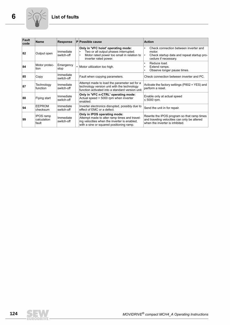
6
124 MOVIDRIVE® compact MCH4_A Operating Instructions
List of faults
82 Output openImmediate switch-off
Only in 'VFC hoist' operating mode:• Two or all output phases interrupted.• Motor rated power too small in relation to
inverter rated power.
• Check connection between inverter and motor.
• Check startup data and repeat startup pro-cedure if necessary.
84Motor protec-tion
Emergency stop
• Motor utilization too high.• Reduce load.• Extend ramps.• Observe longer pause times.
85 CopyImmediate switch-off
Fault when copying parameters. Check connection between inverter and PC.
87Technology function
Immediate switch-off
Attempt made to load the parameter set for a technology version unit with the technology function activated into a standard version unit.
Activate the factory settings (P802 = YES) and perform a reset.
88 Flying startImmediate switch-off
Only in 'VFC n-CTRL' operating mode:Actual speed > 5000 rpm when inverter enabled.
Enable only at actual speed≤ 5000 rpm.
94EEPROM checksum
Immediate switch-off
Inverter electronics disrupted, possibly due to effect of EMC or a defect.
Send the unit in for repair.
99IPOS ramp calculation fault
Immediate switch-off
Only in IPOS operating mode:Attempt made to alter ramp times and travel-ing velocities when the inverter is enabled, with a sine or squared positioning ramp.
Rewrite the IPOS program so that ramp times and traveling velocities can only be altered when the inverter is inhibited.
Fault code
Name Response P Possible cause Action
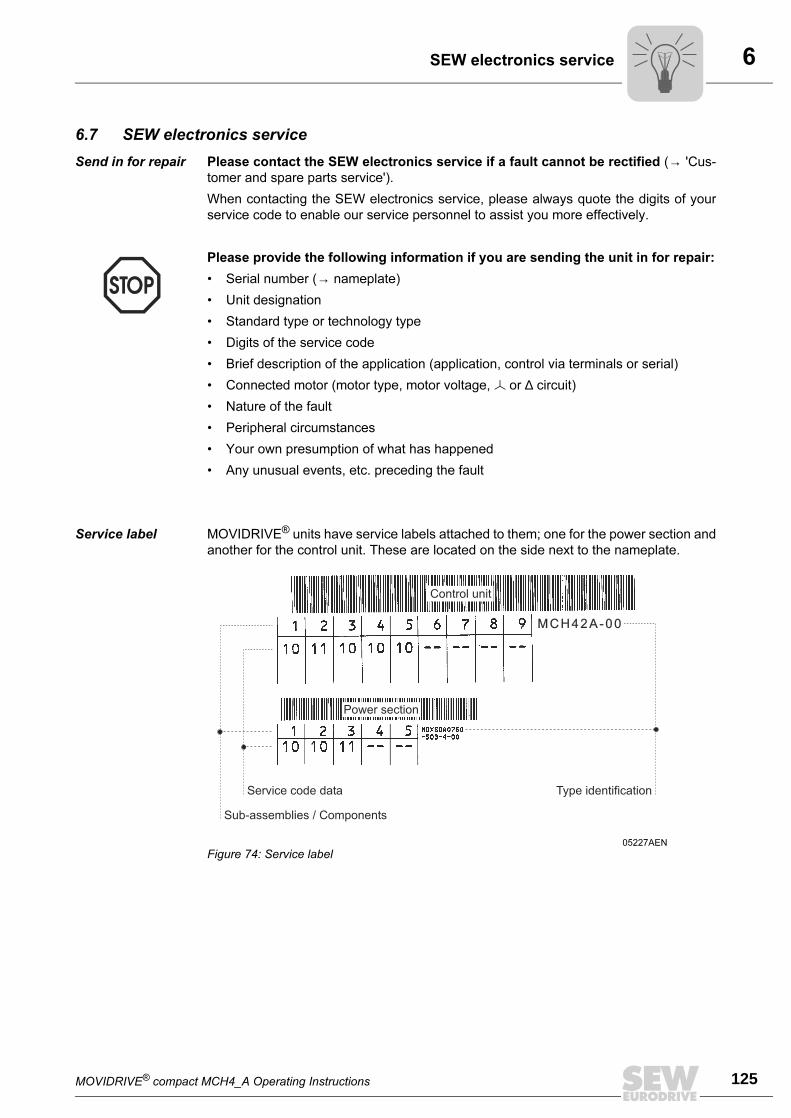
MOVIDRIVE® compact MCH4_A Operating Instructions 125
6SEW electronics service
6.7 SEW electronics service
Send in for repair Please contact the SEW electronics service if a fault cannot be rectified (→ 'Cus-
tomer and spare parts service').
When contacting the SEW electronics service, please always quote the digits of your
service code to enable our service personnel to assist you more effectively.
Service label MOVIDRIVE® units have service labels attached to them; one for the power section and
another for the control unit. These are located on the side next to the nameplate.
Please provide the following information if you are sending the unit in for repair:
• Serial number (→ nameplate)
• Unit designation
• Standard type or technology type
• Digits of the service code
• Brief description of the application (application, control via terminals or serial)
• Connected motor (motor type, motor voltage, or ∆ circuit)
• Nature of the fault
• Peripheral circumstances
• Your own presumption of what has happened
• Any unusual events, etc. preceding the fault
05227AEN
Figure 74: Service label
MCH42A-00
Service code data
Sub-assemblies / Components
Type identification
Power section
Control unit
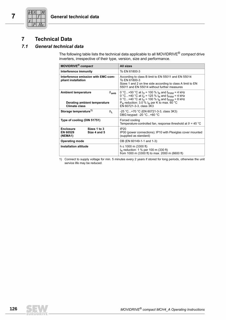
7
126 MOVIDRIVE® compact MCH4_A Operating Instructions
General technical data
7 Technical Data
7.1 General technical data
The following table lists the technical data applicable to all MOVIDRIVE® compact drive
inverters, irrespective of their type, version, size and performance.
MOVIDRIVE® compact All sizes
Interference immunity To EN 61800-3
Interference emission with EMC-com-pliant installation
According to class B limit to EN 55011 and EN 55014To EN 61800-3Sizes 1 and 2 on line side according to class A limit to EN 55011 and EN 55014 without further measures
Ambient temperature ϑamb
Derating ambient temperatureClimate class
0 °C...+50 °C at ID = 100 % IN and fPWM = 4 kHz0 °C...+40 °C at ID = 125 % IN and fPWM = 4 kHz0 °C...+40 °C at ID = 100 % IN and fPWM = 8 kHzPN reduction: 3.0 % IN per K to max. 60 °CEN 60721-3-3, class 3K3
Storage temperature1) ϑL
1) Connect to supply voltage for min. 5 minutes every 2 years if stored for long periods, otherwise the unit
service life may be reduced.
-25 °C...+70 °C (EN 60721-3-3, class 3K3)DBG keypad: -20 °C...+60 °C
Type of cooling (DIN 51751) Forced coolingTemperature-controlled fan, response threshold at ϑ = 45 °C
Enclosure Sizes 1 to 3EN 60529 Size 4 and 5(NEMA1)
IP20IP00 (power connections); IP10 with Plexiglas cover mounted (supplied as standard)
Operating mode DB (EN 60149-1-1 and 1-3)
Installation altitude h ≤ 1000 m (3300 ft)IN reduction: 1 % per 100 m (330 ft)from 1000 m (3300 ft) to max. 2000 m (6600 ft)
Pi
fkVA
Hz
n
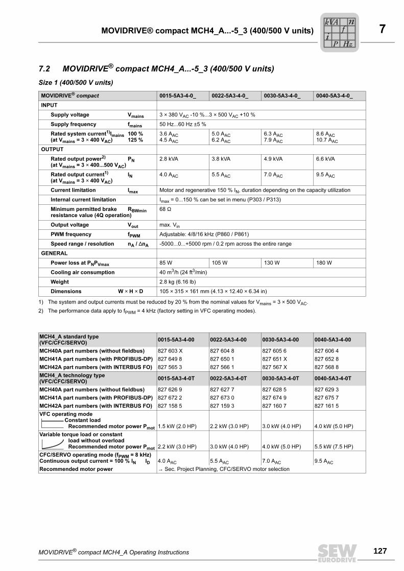
MOVIDRIVE® compact MCH4_A Operating Instructions 127
7MOVIDRIVE® compact MCH4_A...-5_3 (400/500 V units)
7.2 MOVIDRIVE® compact MCH4_A...-5_3 (400/500 V units)
Size 1 (400/500 V units)
MOVIDRIVE® compact 0015-5A3-4-0_ 0022-5A3-4-0_ 0030-5A3-4-0_ 0040-5A3-4-0_
INPUT
Supply voltage Vmains 3 × 380 VAC -10 %...3 × 500 VAC +10 %
Supply frequency fmains 50 Hz...60 Hz ±5 %
Rated system current1)Imains 100 %(at Vmains = 3 × 400 VAC) 125 %
1) The system and output currents must be reduced by 20 % from the nominal values for Vmains = 3 × 500 VAC.
3.6 AAC
4.5 AAC
5.0 AAC
6.2 AAC
6.3 AAC
7.9 AAC
8.6 AAC
10.7 AAC
OUTPUT
Rated output power2) PN(at Vmains = 3 × 400...500 VAC)
2) The performance data apply to fPWM = 4 kHz (factory setting in VFC operating modes).
2.8 kVA 3.8 kVA 4.9 kVA 6.6 kVA
Rated output current1) IN(at Vmains = 3 × 400 VAC)
4.0 AAC 5.5 AAC 7.0 AAC 9.5 AAC
Current limitation Imax Motor and regenerative 150 % IN, duration depending on the capacity utilization
Internal current limitation Imax = 0...150 % can be set in menu (P303 / P313)
Minimum permitted brake RBWminresistance value (4Q operation)
68 Ω
Output voltage Vout max. Vin
PWM frequency fPWM Adjustable: 4/8/16 kHz (P860 / P861)
Speed range / resolution nA / ∆nA -5000...0...+5000 rpm / 0.2 rpm across the entire range
GENERAL
Power loss at PNPVmax 85 W 105 W 130 W 180 W
Cooling air consumption 40 m3/h (24 ft3/min)
Weight 2.8 kg (6.16 lb)
Dimensions W × H × D 105 × 315 × 161 mm (4.13 × 12.40 × 6.34 in)
MCH4_A standard type(VFC/CFC/SERVO)
0015-5A3-4-00 0022-5A3-4-00 0030-5A3-4-00 0040-5A3-4-00
MCH40A part numbers (without fieldbus) 827 603 X 827 604 8 827 605 6 827 606 4
MCH41A part numbers (with PROFIBUS-DP) 827 649 8 827 650 1 827 651 X 827 652 8
MCH42A part numbers (with INTERBUS FO) 827 565 3 827 566 1 827 567 X 827 568 8
MCH4_A technology type(VFC/CFC/SERVO)
0015-5A3-4-0T 0022-5A3-4-0T 0030-5A3-4-0T 0040-5A3-4-0T
MCH40A part numbers (without fieldbus) 827 626 9 827 627 7 827 628 5 827 629 3
MCH41A part numbers (with PROFIBUS-DP) 827 672 2 827 673 0 827 674 9 827 675 7
MCH42A part numbers (with INTERBUS FO) 827 158 5 827 159 3 827 160 7 827 161 5
VFC operating modeConstant load
Recommended motor power Pmot 1.5 kW (2.0 HP) 2.2 kW (3.0 HP) 3.0 kW (4.0 HP) 4.0 kW (5.0 HP)
Variable torque load or constantload without overloadRecommended motor power Pmot 2.2 kW (3.0 HP) 3.0 kW (4.0 HP) 4.0 kW (5.0 HP) 5.5 kW (7.5 HP)
CFC/SERVO operating mode (fPWM = 8 kHz)Continuous output current = 100 % IN ID 4.0 AAC 5.5 AAC 7.0 AAC 9.5 AAC
Recommended motor power → Sec. Project Planning, CFC/SERVO motor selection
Pi
fkVA
Hz
n
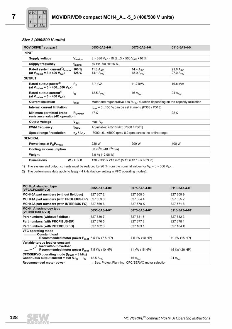
7
128 MOVIDRIVE® compact MCH4_A Operating Instructions
MOVIDRIVE® compact MCH4_A...-5_3 (400/500 V units)
Size 2 (400/500 V units)
MOVIDRIVE® compact 0055-5A3-4-0_ 0075-5A3-4-0_ 0110-5A3-4-0_
INPUT
Supply voltage Vmains 3 × 380 VAC -10 %...3 × 500 VAC +10 %
Supply frequency fmains 50 Hz...60 Hz ±5 %
Rated system current1)Imains 100 %(at Vmains = 3 × 400 VAC) 125 %
1) The system and output currents must be reduced by 20 % from the nominal values for Vin = 3 × 500 VAC.
11.3 AAC
14.1 AAC
14.4 AAC
18.0 AAC
21.6 AAC
27.0 AAC
OUTPUT
Rated output power2) PN(at Vmains = 3 × 400...500 VAC)
2) The performance data apply to fPWM = 4 kHz (factory setting in VFC operating modes).
8.7 kVA 11.2 kVA 16.8 kVA
Rated output current1) IN(at Vmains = 3 × 400 VAC)
12.5 AAC 16 AAC 24 AAC
Current limitation Imax Motor and regenerative 150 % IN, duration depending on the capacity utilization
Internal current limitation Imax = 0...150 % can be set in menu (P303 / P313)
Minimum permitted brake RBWminresistance value (4Q operation)
47 Ω 22 Ω
Output voltage Vout max. Vin
PWM frequency fPWM Adjustable: 4/8/16 kHz (P860 / P861)
Speed range / resolution nA / ∆nA -5000...0...+5000 rpm / 0.2 rpm across the entire range
GENERAL
Power loss at PNPVmax 220 W 290 W 400 W
Cooling air consumption 80 m3/h (48 ft3/min)
Weight 5.9 kg (12.98 lb)
Dimensions W × H × D 130 × 335 × 213 mm (5.12 × 13.19 × 8.39 in)
MCH4_A standard type(VFC/CFC/SERVO)
0055-5A3-4-00 0075-5A3-4-00 0110-5A3-4-00
MCH40A part numbers (without fieldbus) 827 607 2 827 608 0 827 609 9
MCH41A part numbers (with PROFIBUS-DP) 827 653 6 827 654 4 827 655 2
MCH42A part numbers (with INTERBUS FO) 827 569 6 827 570 X 827 571 8
MCH4_A technology type(VFC/CFC/SERVO)
0055-5A3-4-0T 0075-5A3-4-0T 0110-5A3-4-0T
Part numbers (without fieldbus) 827 630 7 827 631 5 827 632 3
Part numbers (with PROFIBUS-DP) 827 676 5 827 677 3 827 678 1
Part numbers (with INTERBUS FO) 827 162 3 827 163 1 827 164 X
VFC operating modeConstant load
Recommended motor power Pmot 5.5 kW (7.5 HP) 7.5 kW (10 HP) 11 kW (15 HP)
Variable torque load or constantload without overloadRecommended motor power Pmot 7.5 kW (10 HP) 11 kW (15 HP) 15 kW (20 HP)
CFC/SERVO operating mode (fPWM = 8 kHz)Continuous output current = 100 % IN ID 12.5 AAC 16 AAC 24 AAC
Recommended motor power → Sec. Project Planning, CFC/SERVO motor selection
Pi
fkVA
Hz
n
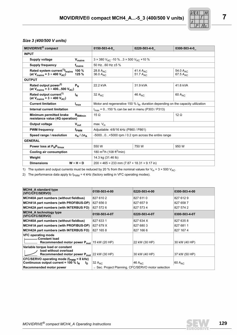
MOVIDRIVE® compact MCH4_A Operating Instructions 129
7MOVIDRIVE® compact MCH4_A...-5_3 (400/500 V units)
Size 3 (400/500 V units)
MOVIDRIVE® compact 0150-503-4-0_ 0220-503-4-0_ 0300-503-4-0_
INPUT
Supply voltage Vmains 3 × 380 VAC -10 %...3 × 500 VAC +10 %
Supply frequency fmains 50 Hz...60 Hz ±5 %
Rated system current1)Imains 100 %(at Vmains = 3 × 400 VAC) 125 %
1) The system and output currents must be reduced by 20 % from the nominal values for Vin = 3 × 500 VAC.
28.8 AAC
36.0 AAC
41.4 AAC
51.7 AAC
54.0 AAC
67.5 AAC
OUTPUT
Rated output power2) PN(at Vmains = 3 × 400...500 VAC)
2) The performance data apply to fPWM = 4 kHz (factory setting in VFC operating modes).
22.2 kVA 31.9 kVA 41.6 kVA
Rated output current1) IN(at Vmains = 3 × 400 VAC)
32 AAC 46 AAC 60 AAC
Current limitation Imax Motor and regenerative 150 % IN, duration depending on the capacity utilization
Internal current limitation Imax = 0...150 % can be set in menu (P303 / P313)
Minimum permitted brake RBWminresistance value (4Q operation)
15 Ω 12 Ω
Output voltage Vout max. Vin
PWM frequency fPWM Adjustable: 4/8/16 kHz (P860 / P861)
Speed range / resolution nA / ∆nA -5000...0...+5000 rpm / 0.2 rpm across the entire range
GENERAL
Power loss at PNPVmax 550 W 750 W 950 W
Cooling air consumption 180 m3/h (108 ft3/min)
Weight 14.3 kg (31.46 lb)
Dimensions W × H × D 200 × 465 × 233 mm (7.87 × 18.31 × 9.17 in)
MCH4_A standard type(VFC/CFC/SERVO)
0150-503-4-00 0220-503-4-00 0300-503-4-00
MCH40A part numbers (without fieldbus) 827 610 2 827 611 0 827 612 9
MCH41A part numbers (with PROFIBUS-DP) 827 656 0 827 657 9 827 658 7
MCH42A part numbers (with INTERBUS FO) 827 572 6 827 573 4 827 574 2
MCH4_A technology type(VFC/CFC/SERVO)
0150-503-4-0T 0220-503-4-0T 0300-503-4-0T
MCH40A part numbers (without fieldbus) 827 633 1 827 634 X 827 635 8
MCH41A part numbers (with PROFIBUS-DP) 827 679 X 827 680 3 827 681 1
MCH42A part numbers (with INTERBUS FO) 827 165 8 827 166 6 827 167 4
VFC operating modeConstant load
Recommended motor power Pmot 15 kW (20 HP) 22 kW (30 HP) 30 kW (40 HP)
Variable torque load or constantload without overloadRecommended motor power Pmot 22 kW (30 HP) 30 kW (40 HP) 37 kW (50 HP)
CFC/SERVO operating mode (fPWM = 8 kHz)Continuous output current = 100 % IN ID 32 AAC 46 AAC 60 AAC
Recommended motor power → Sec. Project Planning, CFC/SERVO motor selection
Pi
fkVA
Hz
n
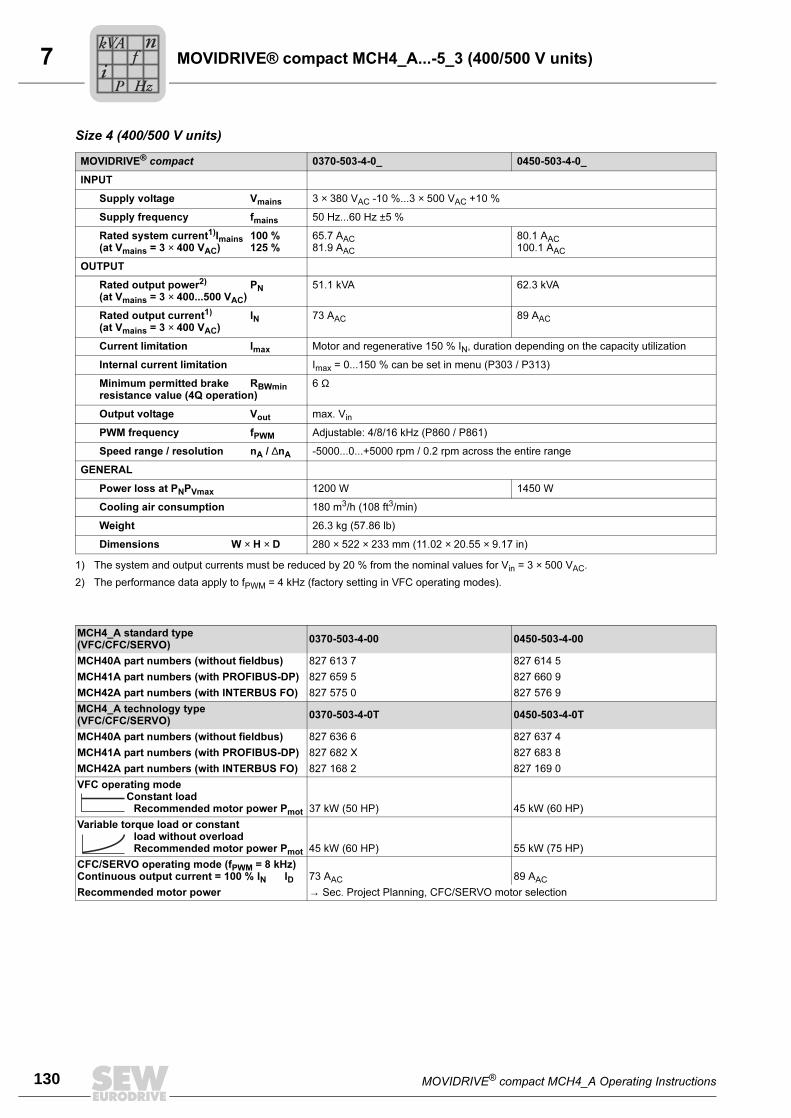
7
130 MOVIDRIVE® compact MCH4_A Operating Instructions
MOVIDRIVE® compact MCH4_A...-5_3 (400/500 V units)
Size 4 (400/500 V units)
MOVIDRIVE® compact 0370-503-4-0_ 0450-503-4-0_
INPUT
Supply voltage Vmains 3 × 380 VAC -10 %...3 × 500 VAC +10 %
Supply frequency fmains 50 Hz...60 Hz ±5 %
Rated system current1)Imains 100 %(at Vmains = 3 × 400 VAC) 125 %
1) The system and output currents must be reduced by 20 % from the nominal values for Vin = 3 × 500 VAC.
65.7 AAC
81.9 AAC
80.1 AAC
100.1 AAC
OUTPUT
Rated output power2) PN(at Vmains = 3 × 400...500 VAC)
2) The performance data apply to fPWM = 4 kHz (factory setting in VFC operating modes).
51.1 kVA 62.3 kVA
Rated output current1) IN(at Vmains = 3 × 400 VAC)
73 AAC 89 AAC
Current limitation Imax Motor and regenerative 150 % IN, duration depending on the capacity utilization
Internal current limitation Imax = 0...150 % can be set in menu (P303 / P313)
Minimum permitted brake RBWminresistance value (4Q operation)
6 Ω
Output voltage Vout max. Vin
PWM frequency fPWM Adjustable: 4/8/16 kHz (P860 / P861)
Speed range / resolution nA / ∆nA -5000...0...+5000 rpm / 0.2 rpm across the entire range
GENERAL
Power loss at PNPVmax 1200 W 1450 W
Cooling air consumption 180 m3/h (108 ft3/min)
Weight 26.3 kg (57.86 lb)
Dimensions W × H × D 280 × 522 × 233 mm (11.02 × 20.55 × 9.17 in)
MCH4_A standard type(VFC/CFC/SERVO)
0370-503-4-00 0450-503-4-00
MCH40A part numbers (without fieldbus) 827 613 7 827 614 5
MCH41A part numbers (with PROFIBUS-DP) 827 659 5 827 660 9
MCH42A part numbers (with INTERBUS FO) 827 575 0 827 576 9
MCH4_A technology type(VFC/CFC/SERVO)
0370-503-4-0T 0450-503-4-0T
MCH40A part numbers (without fieldbus) 827 636 6 827 637 4
MCH41A part numbers (with PROFIBUS-DP) 827 682 X 827 683 8
MCH42A part numbers (with INTERBUS FO) 827 168 2 827 169 0
VFC operating modeConstant load
Recommended motor power Pmot 37 kW (50 HP) 45 kW (60 HP)
Variable torque load or constantload without overloadRecommended motor power Pmot 45 kW (60 HP) 55 kW (75 HP)
CFC/SERVO operating mode (fPWM = 8 kHz)Continuous output current = 100 % IN ID 73 AAC 89 AAC
Recommended motor power → Sec. Project Planning, CFC/SERVO motor selection
Pi
fkVA
Hz
n
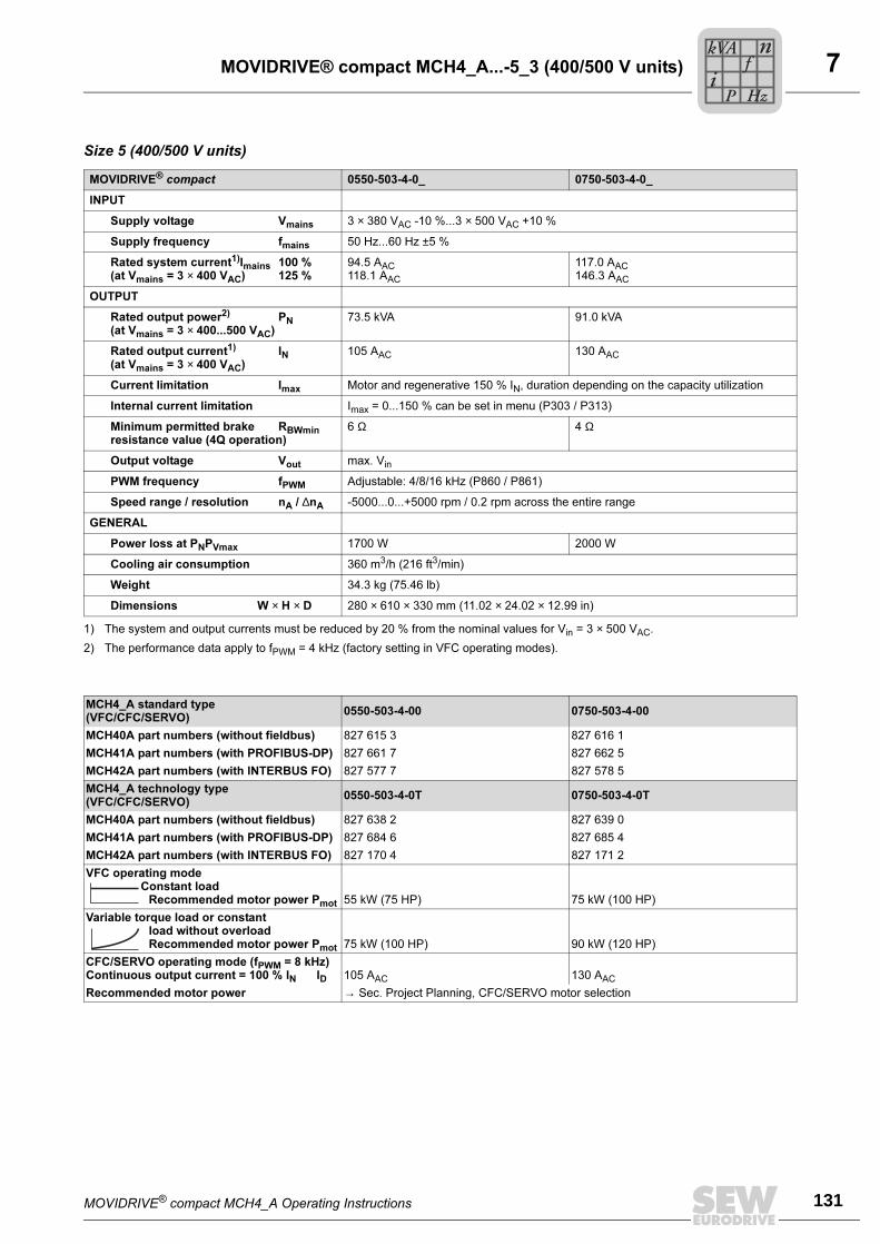
MOVIDRIVE® compact MCH4_A Operating Instructions 131
7MOVIDRIVE® compact MCH4_A...-5_3 (400/500 V units)
Size 5 (400/500 V units)
MOVIDRIVE® compact 0550-503-4-0_ 0750-503-4-0_
INPUT
Supply voltage Vmains 3 × 380 VAC -10 %...3 × 500 VAC +10 %
Supply frequency fmains 50 Hz...60 Hz ±5 %
Rated system current1)Imains 100 %(at Vmains = 3 × 400 VAC) 125 %
1) The system and output currents must be reduced by 20 % from the nominal values for Vin = 3 × 500 VAC.
94.5 AAC
118.1 AAC
117.0 AAC
146.3 AAC
OUTPUT
Rated output power2) PN(at Vmains = 3 × 400...500 VAC)
2) The performance data apply to fPWM = 4 kHz (factory setting in VFC operating modes).
73.5 kVA 91.0 kVA
Rated output current1) IN(at Vmains = 3 × 400 VAC)
105 AAC 130 AAC
Current limitation Imax Motor and regenerative 150 % IN, duration depending on the capacity utilization
Internal current limitation Imax = 0...150 % can be set in menu (P303 / P313)
Minimum permitted brake RBWminresistance value (4Q operation)
6 Ω 4 Ω
Output voltage Vout max. Vin
PWM frequency fPWM Adjustable: 4/8/16 kHz (P860 / P861)
Speed range / resolution nA / ∆nA -5000...0...+5000 rpm / 0.2 rpm across the entire range
GENERAL
Power loss at PNPVmax 1700 W 2000 W
Cooling air consumption 360 m3/h (216 ft3/min)
Weight 34.3 kg (75.46 lb)
Dimensions W × H × D 280 × 610 × 330 mm (11.02 × 24.02 × 12.99 in)
MCH4_A standard type(VFC/CFC/SERVO)
0550-503-4-00 0750-503-4-00
MCH40A part numbers (without fieldbus) 827 615 3 827 616 1
MCH41A part numbers (with PROFIBUS-DP) 827 661 7 827 662 5
MCH42A part numbers (with INTERBUS FO) 827 577 7 827 578 5
MCH4_A technology type(VFC/CFC/SERVO)
0550-503-4-0T 0750-503-4-0T
MCH40A part numbers (without fieldbus) 827 638 2 827 639 0
MCH41A part numbers (with PROFIBUS-DP) 827 684 6 827 685 4
MCH42A part numbers (with INTERBUS FO) 827 170 4 827 171 2
VFC operating modeConstant load
Recommended motor power Pmot 55 kW (75 HP) 75 kW (100 HP)
Variable torque load or constantload without overloadRecommended motor power Pmot 75 kW (100 HP) 90 kW (120 HP)
CFC/SERVO operating mode (fPWM = 8 kHz)Continuous output current = 100 % IN ID 105 AAC 130 AAC
Recommended motor power → Sec. Project Planning, CFC/SERVO motor selection
Pi
fkVA
Hz
n
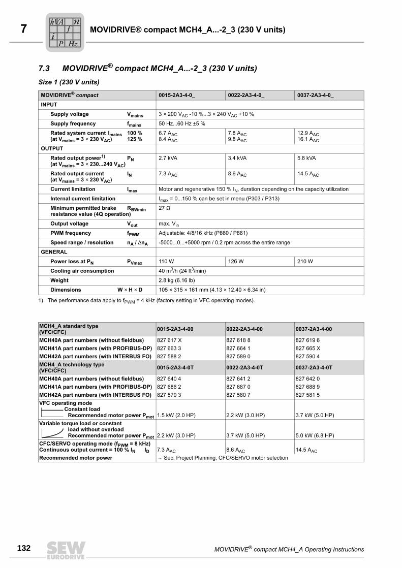
7
132 MOVIDRIVE® compact MCH4_A Operating Instructions
MOVIDRIVE® compact MCH4_A...-2_3 (230 V units)
7.3 MOVIDRIVE® compact MCH4_A...-2_3 (230 V units)
Size 1 (230 V units)
MOVIDRIVE® compact 0015-2A3-4-0_ 0022-2A3-4-0_ 0037-2A3-4-0_
INPUT
Supply voltage Vmains 3 × 200 VAC -10 %...3 × 240 VAC +10 %
Supply frequency fmains 50 Hz...60 Hz ±5 %
Rated system current Imains 100 %(at Vmains = 3 × 230 VAC) 125 %
6.7 AAC8.4 AAC
7.8 AAC9.8 AAC
12.9 AAC16.1 AAC
OUTPUT
Rated output power1) PN(at Vmains = 3 × 230...240 VAC)
1) The performance data apply to fPWM = 4 kHz (factory setting in VFC operating modes).
2.7 kVA 3.4 kVA 5.8 kVA
Rated output current IN(at Vmains = 3 × 230 VAC)
7.3 AAC 8.6 AAC 14.5 AAC
Current limitation Imax Motor and regenerative 150 % IN, duration depending on the capacity utilization
Internal current limitation Imax = 0...150 % can be set in menu (P303 / P313)
Minimum permitted brake RBWminresistance value (4Q operation)
27 Ω
Output voltage Vout max. Vin
PWM frequency fPWM Adjustable: 4/8/16 kHz (P860 / P861)
Speed range / resolution nA / ∆nA -5000...0...+5000 rpm / 0.2 rpm across the entire range
GENERAL
Power loss at PN PVmax 110 W 126 W 210 W
Cooling air consumption 40 m3/h (24 ft3/min)
Weight 2.8 kg (6.16 lb)
Dimensions W × H × D 105 × 315 × 161 mm (4.13 × 12.40 × 6.34 in)
MCH4_A standard type(VFC/CFC)
0015-2A3-4-00 0022-2A3-4-00 0037-2A3-4-00
MCH40A part numbers (without fieldbus) 827 617 X 827 618 8 827 619 6
MCH41A part numbers (with PROFIBUS-DP) 827 663 3 827 664 1 827 665 X
MCH42A part numbers (with INTERBUS FO) 827 588 2 827 589 0 827 590 4
MCH4_A technology type(VFC/CFC)
0015-2A3-4-0T 0022-2A3-4-0T 0037-2A3-4-0T
MCH40A part numbers (without fieldbus) 827 640 4 827 641 2 827 642 0
MCH41A part numbers (with PROFIBUS-DP) 827 686 2 827 687 0 827 688 9
MCH42A part numbers (with INTERBUS FO) 827 579 3 827 580 7 827 581 5
VFC operating modeConstant load
Recommended motor power Pmot 1.5 kW (2.0 HP) 2.2 kW (3.0 HP) 3.7 kW (5.0 HP)
Variable torque load or constantload without overloadRecommended motor power Pmot 2.2 kW (3.0 HP) 3.7 kW (5.0 HP) 5.0 kW (6.8 HP)
CFC/SERVO operating mode (fPWM = 8 kHz)Continuous output current = 100 % IN ID 7.3 AAC 8.6 AAC 14.5 AAC
Recommended motor power → Sec. Project Planning, CFC/SERVO motor selection
Pi
fkVA
Hz
n

MOVIDRIVE® compact MCH4_A Operating Instructions 133
7MOVIDRIVE® compact MCH4_A...-2_3 (230 V units)
Size 2 (230 V units)
MOVIDRIVE® compact 0055-2A3-4-0_ 0075-2A3-4-0_
INPUT
Supply voltage Vmains 3 × 200 VAC -10 %...3 × 240 VAC +10 %
Supply frequency fmains 50 Hz...60 Hz ±5 %
Rated system current Imains 100 %(at Vmains = 3 × 230 VAC) 125 %
19.5 AAC24.4 AAC
27.4 AAC34.3 AAC
OUTPUT
Output rated power1) PN(at Vmains = 3 × 230...240 VAC)
1) The performance data apply to fPWM = 4 kHz (factory setting in VFC operating modes).
8.8 kVA 11.6 kVA
Output rated current IN(at Vmains = 3 × 230 VAC)
22 AAC 29 AAC
Current limitation Imax Motor and regenerative 150 % IN, duration depending on the capacity utilization
Internal current limitation Imax = 0...150 % can be set in menu (P303 / P313)
Minimum permitted brake RBWminresistance value (4Q operation)
12 Ω
Output voltage Vout max. Vin
PWM frequency fPWM Adjustable: 4/8/16 kHz (P860 / P861)
Speed range / resolution nA / ∆nA -5000...0...+5000 rpm / 0.2 rpm across the entire range
GENERAL
Power loss at PN PVmax 300 W 380 W
Cooling air consumption 80 m3/h (48 ft3/min)
Weight 5.9 kg (12.98 lb)
Dimensions W × H × D 130 × 335 × 213 mm (5.12 × 13.19 × 8.39 in)
MCH4_A standard type(VFC/CFC)
0055-2A3-4-00 0075-2A3-4-00
MCH40A part numbers (without fieldbus) 827 620 X 827 621 8
MCH41A part numbers (with PROFIBUS-DP) 827 666 8 827 667 6
MCH42A part numbers (with INTERBUS FO) 827 591 2 827 592 0
MCH4_A technology type(VFC/CFC)
0055-2A3-4-0T 0075-2A3-4-0T
MCH40A part numbers (without fieldbus) 827 643 9 827 644 7
MCH41A part numbers (with PROFIBUS-DP) 827 689 7 827 690 0
MCH42A part numbers (with INTERBUS FO) 827 582 3 827 583 1
VFC operating modeConstant load
Recommended motor power Pmot
5.5 kW (7.5 HP) 7.5 kW (10 HP)
Variable torque load or constantload without overloadRecommended motor power Pmot 7.5 kW (10 HP) 11 kW (15 HP)
CFC/SERVO operating mode (fPWM = 8 kHz)Continuous output current = 100 % IN ID 22 AAC 29 AAC
Recommended motor power → Sec. Project Planning, CFC/SERVO motor selection
Pi
fkVA
Hz
n
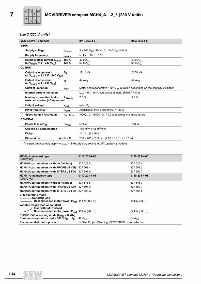
7
134 MOVIDRIVE® compact MCH4_A Operating Instructions
MOVIDRIVE® compact MCH4_A...-2_3 (230 V units)
Size 3 (230 V units)
MOVIDRIVE® compact 0110-203-4-0_ 0150-203-4-0_
INPUT
Supply voltage Vmains 3 × 200 VAC -10 %...3 × 240 VAC +10 %
Supply frequency fmains 50 Hz...60 Hz ±5 %
Rated system current Imains 100 %(at Vmains = 3 × 230 VAC) 125 %
40.0 AAC50.0 AAC
49.0 AAC61.0 AAC
OUTPUT
Output rated power1) PN(at Vmains = 3 × 230...240 VAC)
1) The performance data apply to fPWM = 4 kHz (factory setting in VFC operating modes).
17.1 kVA 21.5 kVA
Output rated current IN(at Vmains = 3 × 230 VAC)
42 AAC 54 AAC
Current limitation Imax Motor and regenerative 150 % IN, duration depending on the capacity utilization
Internal current limitation Imax = 0...150 % can be set in menu (P303 / P313)
Minimum permitted brake RBWminresistance value (4Q operation)
7.5 Ω 5.6 Ω
Output voltage Vout max. Vin
PWM frequency fPWM Adjustable: 4/8/16 kHz (P860 / P861)
Speed range / resolution nA / ∆nA -5000...0...+5000 rpm / 0.2 rpm across the entire range
GENERAL
Power loss at PN PVmax 580 W 720 W
Cooling air consumption 180 m3/h (108 ft3/min)
Weight 14.3 kg (31.46 lb)
Dimensions W × H × D 200 × 465 × 233 mm (7.87 × 18.31 × 9.17 in)
MCH4_A standard type(VFC/CFC)
0110-203-4-00 0150-203-4-00
MCH40A part numbers (without fieldbus) 827 622 6 827 623 4
MCH41A part numbers (with PROFIBUS-DP) 827 668 4 827 669 2
MCH42A part numbers (with INTERBUS FO) 827 593 9 827 594 7
MCH4_A technology type(VFC/CFC)
0110-203-4-0T 0150-203-4-0T
MCH40A part numbers (without fieldbus) 827 645 5 827 646 3
MCH41A part numbers (with PROFIBUS-DP) 827 691 9 827 692 7
MCH42A part numbers (with INTERBUS FO) 827 584 X 827 585 8
VFC operating modeConstant load
Recommended motor power Pmot 11 kW (15 HP) 15 kW (20 HP)
Variable torque load or constantload without overloadRecommended motor power Pmot 15 kW (20 HP) 22 kW (30 HP)
CFC/SERVO operating mode (fPWM = 8 kHz)Continuous output current = 100 % IN ID 42 AAC 54 AAC
Recommended motor power → Sec. Project Planning, CFC/SERVO motor selection
Pi
fkVA
Hz
n
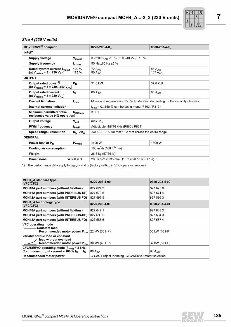
MOVIDRIVE® compact MCH4_A Operating Instructions 135
7MOVIDRIVE® compact MCH4_A...-2_3 (230 V units)
Size 4 (230 V units)
MOVIDRIVE® compact 0220-203-4-0_ 0300-203-4-0_
INPUT
Supply voltage Vmains 3 × 200 VAC -10 %...3 × 240 VAC +10 %
Supply frequency fmains 50 Hz...60 Hz ±5 %
Rated system current Imains 100 %(at Vmains = 3 × 230 VAC) 125 %
72 AAC90 AAC
86 AAC107 AAC
OUTPUT
Output rated power1) PN(at Vmains = 3 × 230...240 VAC)
1) The performance data apply to fPWM = 4 kHz (factory setting in VFC operating modes).
31.8 kVA 37.8 kVA
Output rated current IN(at Vmains = 3 × 230 VAC)
80 AAC 95 AAC
Current limitation Imax Motor and regenerative 150 % IN, duration depending on the capacity utilization
Internal current limitation Imax = 0...150 % can be set in menu (P303 / P313)
Minimum permitted brake RBWminresistance value (4Q operation)
3.0 Ω
Output voltage Vout max. Vin
PWM frequency fPWM Adjustable: 4/8/16 kHz (P860 / P861)
Speed range / resolution nA / ∆nA -5000...0...+5000 rpm / 0.2 rpm across the entire range
GENERAL
Power loss at PN PVmax 1100 W 1300 W
Cooling air consumption 180 m3/h (108 ft3/min)
Weight 26.3 kg (57.86 lb)
Dimensions W × H × D 280 × 522 × 233 mm (11.02 × 20.55 × 9.17 in)
MCH4_A standard type(VFC/CFC)
0220-203-4-00 0300-203-4-00
MCH40A part numbers (without fieldbus) 827 624 2 827 625 0
MCH41A part numbers (with PROFIBUS-DP) 827 670 6 827 671 4
MCH42A part numbers (with INTERBUS FO) 827 595 5 827 596 3
MCH4_A technology type(VFC/CFC)
0220-203-4-0T 0300-203-4-0T
MCH40A part numbers (without fieldbus) 827 647 1 827 648 X
MCH41A part numbers (with PROFIBUS-DP) 827 693 5 827 694 3
MCH42A part numbers (with INTERBUS FO) 827 586 6 827 587 4
VFC operating modeConstant load
Recommended motor power Pmot 22 kW (30 HP) 30 kW (40 HP)
Variable torque load or constantload without overloadRecommended motor power Pmot 30 kW (40 HP) 37 kW (50 HP)
CFC/SERVO operating mode (fPWM = 8 kHz)Continuous output current = 100 % IN ID 80 AAC 95 AAC
Recommended motor power → Sec. Project Planning, CFC/SERVO motor selection
Pi
fkVA
Hz
n
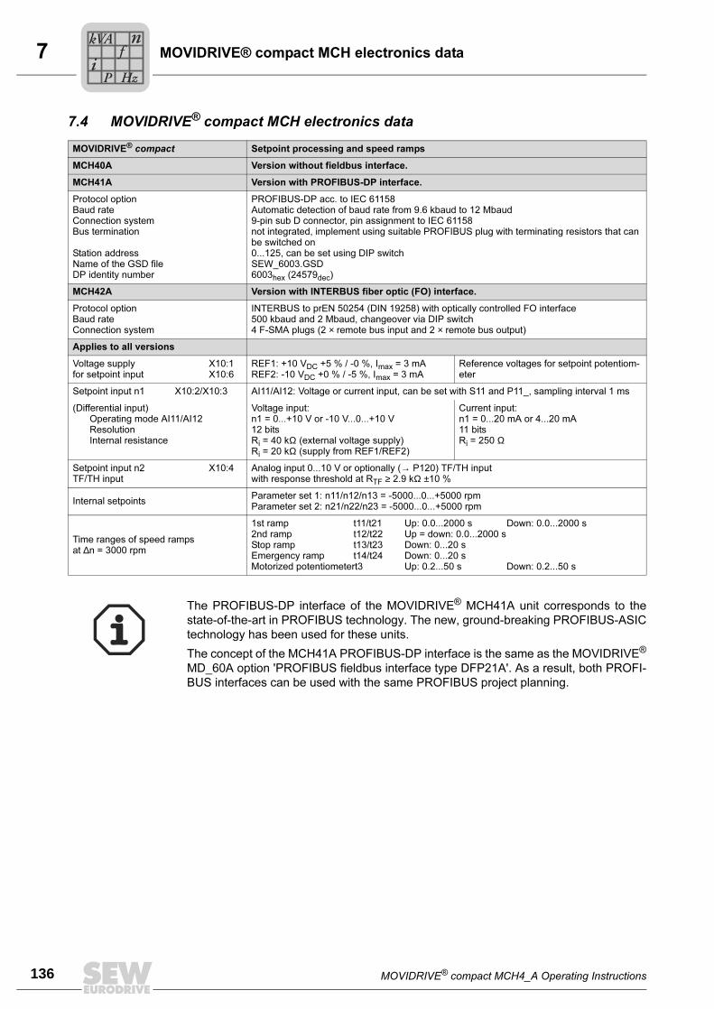
7
136 MOVIDRIVE® compact MCH4_A Operating Instructions
MOVIDRIVE® compact MCH electronics data
7.4 MOVIDRIVE® compact MCH electronics data
MOVIDRIVE® compact Setpoint processing and speed ramps
MCH40A Version without fieldbus interface.
MCH41A Version with PROFIBUS-DP interface.
Protocol optionBaud rateConnection systemBus termination
Station addressName of the GSD fileDP identity number
PROFIBUS-DP acc. to IEC 61158Automatic detection of baud rate from 9.6 kbaud to 12 Mbaud9-pin sub D connector, pin assignment to IEC 61158not integrated, implement using suitable PROFIBUS plug with terminating resistors that can be switched on0...125, can be set using DIP switchSEW_6003.GSD6003hex (24579dec)
MCH42A Version with INTERBUS fiber optic (FO) interface.
Protocol optionBaud rateConnection system
INTERBUS to prEN 50254 (DIN 19258) with optically controlled FO interface500 kbaud and 2 Mbaud, changeover via DIP switch4 F-SMA plugs (2 × remote bus input and 2 × remote bus output)
Applies to all versions
Voltage supply X10:1for setpoint input X10:6
REF1: +10 VDC +5 % / -0 %, Imax = 3 mAREF2: -10 VDC +0 % / -5 %, Imax = 3 mA
Reference voltages for setpoint potentiom-eter
Setpoint input n1 X10:2/X10:3 AI11/AI12: Voltage or current input, can be set with S11 and P11_, sampling interval 1 ms
(Differential input)Operating mode AI11/AI12ResolutionInternal resistance
Voltage input:n1 = 0...+10 V or -10 V...0...+10 V12 bitsRi = 40 kΩ (external voltage supply)Ri = 20 kΩ (supply from REF1/REF2)
Current input:n1 = 0...20 mA or 4...20 mA11 bitsRi = 250 Ω
Setpoint input n2 X10:4TF/TH input
Analog input 0...10 V or optionally (→ P120) TF/TH inputwith response threshold at RTF ≥ 2.9 kΩ ±10 %
Internal setpointsParameter set 1: n11/n12/n13 = -5000...0...+5000 rpmParameter set 2: n21/n22/n23 = -5000...0...+5000 rpm
Time ranges of speed rampsat ∆n = 3000 rpm
1st ramp t11/t21 Up: 0.0...2000 s Down: 0.0...2000 s2nd ramp t12/t22 Up = down: 0.0...2000 sStop ramp t13/t23 Down: 0...20 sEmergency ramp t14/t24 Down: 0...20 sMotorized potentiometert3 Up: 0.2...50 s Down: 0.2...50 s
The PROFIBUS-DP interface of the MOVIDRIVE® MCH41A unit corresponds to the
state-of-the-art in PROFIBUS technology. The new, ground-breaking PROFIBUS-ASIC
technology has been used for these units.
The concept of the MCH41A PROFIBUS-DP interface is the same as the MOVIDRIVE®
MD_60A option 'PROFIBUS fieldbus interface type DFP21A'. As a result, both PROFI-
BUS interfaces can be used with the same PROFIBUS project planning.
Pi
fkVA
Hz
n
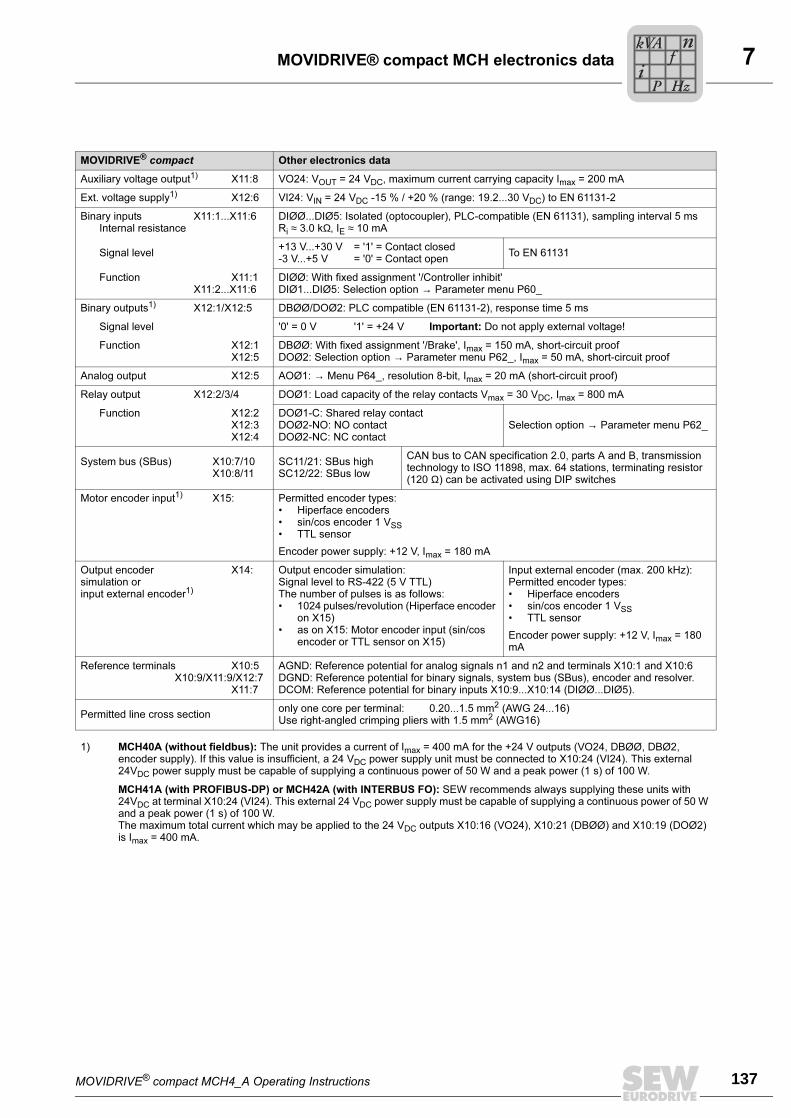
MOVIDRIVE® compact MCH4_A Operating Instructions 137
7MOVIDRIVE® compact MCH electronics data
MOVIDRIVE® compact Other electronics data
Auxiliary voltage output1) X11:8 VO24: VOUT = 24 VDC, maximum current carrying capacity Imax = 200 mA
Ext. voltage supply1) X12:6 VI24: VIN = 24 VDC -15 % / +20 % (range: 19.2...30 VDC) to EN 61131-2
Binary inputs X11:1...X11:6Internal resistance
DIØØ...DIØ5: Isolated (optocoupler), PLC-compatible (EN 61131), sampling interval 5 msRi ≈ 3.0 kΩ, IE ≈ 10 mA
Signal level+13 V...+30 V = '1' = Contact closed-3 V...+5 V = '0' = Contact open
To EN 61131
Function X11:1X11:2...X11:6
DIØØ: With fixed assignment '/Controller inhibit'DIØ1...DIØ5: Selection option → Parameter menu P60_
Binary outputs1) X12:1/X12:5 DBØØ/DOØ2: PLC compatible (EN 61131-2), response time 5 ms
Signal level '0' = 0 V '1' = +24 V Important: Do not apply external voltage!
Function X12:1X12:5
DBØØ: With fixed assignment '/Brake', Imax = 150 mA, short-circuit proofDOØ2: Selection option → Parameter menu P62_, Imax = 50 mA, short-circuit proof
Analog output X12:5 AOØ1: → Menu P64_, resolution 8-bit, Imax = 20 mA (short-circuit proof)
Relay output X12:2/3/4 DOØ1: Load capacity of the relay contacts Vmax = 30 VDC, Imax = 800 mA
Function X12:2X12:3X12:4
DOØ1-C: Shared relay contactDOØ2-NO: NO contactDOØ2-NC: NC contact
Selection option → Parameter menu P62_
System bus (SBus) X10:7/10X10:8/11
SC11/21: SBus highSC12/22: SBus low
CAN bus to CAN specification 2.0, parts A and B, transmission technology to ISO 11898, max. 64 stations, terminating resistor (120 Ω) can be activated using DIP switches
Motor encoder input1) X15: Permitted encoder types:• Hiperface encoders• sin/cos encoder 1 VSS• TTL sensor
Encoder power supply: +12 V, Imax = 180 mA
Output encoder X14:simulation orinput external encoder1)
Output encoder simulation:Signal level to RS-422 (5 V TTL)The number of pulses is as follows:• 1024 pulses/revolution (Hiperface encoder
on X15)• as on X15: Motor encoder input (sin/cos
encoder or TTL sensor on X15)
Input external encoder (max. 200 kHz):Permitted encoder types:• Hiperface encoders• sin/cos encoder 1 VSS• TTL sensor
Encoder power supply: +12 V, Imax = 180 mA
Reference terminals X10:5X10:9/X11:9/X12:7
X11:7
AGND: Reference potential for analog signals n1 and n2 and terminals X10:1 and X10:6DGND: Reference potential for binary signals, system bus (SBus), encoder and resolver.DCOM: Reference potential for binary inputs X10:9...X10:14 (DIØØ...DIØ5).
Permitted line cross sectiononly one core per terminal: 0.20...1.5 mm2 (AWG 24...16)Use right-angled crimping pliers with 1.5 mm2 (AWG16)
1) MCH40A (without fieldbus): The unit provides a current of Imax = 400 mA for the +24 V outputs (VO24, DBØØ, DBØ2, encoder supply). If this value is insufficient, a 24 VDC power supply unit must be connected to X10:24 (VI24). This external 24VDC power supply must be capable of supplying a continuous power of 50 W and a peak power (1 s) of 100 W.
MCH41A (with PROFIBUS-DP) or MCH42A (with INTERBUS FO): SEW recommends always supplying these units with 24VDC at terminal X10:24 (VI24). This external 24 VDC power supply must be capable of supplying a continuous power of 50 W and a peak power (1 s) of 100 W.The maximum total current which may be applied to the 24 VDC outputs X10:16 (VO24), X10:21 (DBØØ) and X10:19 (DOØ2) is Imax = 400 mA.
Pi
fkVA
Hz
n
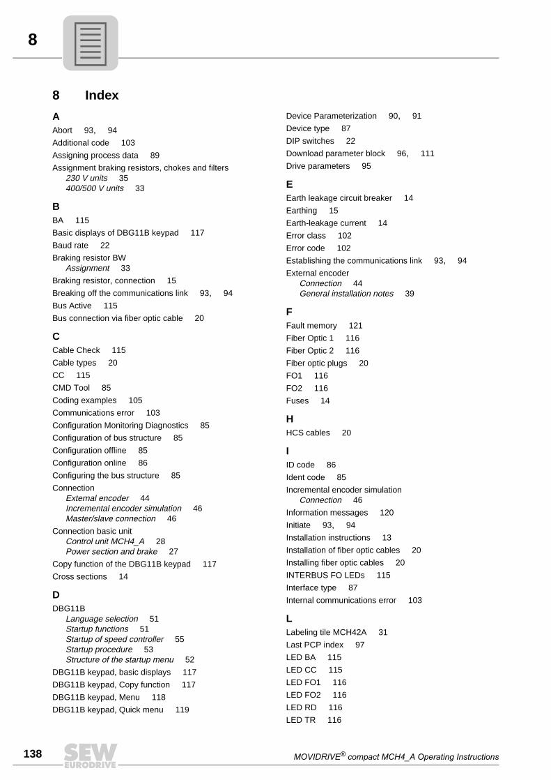
8
138 MOVIDRIVE® compact MCH4_A Operating Instructions
8 Index
AAbort 93, 94
Additional code 103
Assigning process data 89
Assignment braking resistors, chokes and filters230 V units 35400/500 V units 33
BBA 115
Basic displays of DBG11B keypad 117
Baud rate 22
Braking resistor BWAssignment 33
Braking resistor, connection 15
Breaking off the communications link 93, 94
Bus Active 115
Bus connection via fiber optic cable 20
CCable Check 115
Cable types 20
CC 115
CMD Tool 85
Coding examples 105
Communications error 103
Configuration Monitoring Diagnostics 85
Configuration of bus structure 85
Configuration offline 85
Configuration online 86
Configuring the bus structure 85
ConnectionExternal encoder 44Incremental encoder simulation 46Master/slave connection 46
Connection basic unitControl unit MCH4_A 28Power section and brake 27
Copy function of the DBG11B keypad 117
Cross sections 14
DDBG11B
Language selection 51Startup functions 51Startup of speed controller 55Startup procedure 53Structure of the startup menu 52
DBG11B keypad, basic displays 117
DBG11B keypad, Copy function 117
DBG11B keypad, Menu 118
DBG11B keypad, Quick menu 119
Device Parameterization 90, 91
Device type 87
DIP switches 22
Download parameter block 96, 111
Drive parameters 95
EEarth leakage circuit breaker 14
Earthing 15
Earth-leakage current 14
Error class 102
Error code 102
Establishing the communications link 93, 94
External encoderConnection 44General installation notes 39
FFault memory 121
Fiber Optic 1 116
Fiber Optic 2 116
Fiber optic plugs 20
FO1 116
FO2 116
Fuses 14
HHCS cables 20
IID code 86
Ident code 85
Incremental encoder simulationConnection 46
Information messages 120
Initiate 93, 94
Installation instructions 13
Installation of fiber optic cables 20
Installing fiber optic cables 20
INTERBUS FO LEDs 115
Interface type 87
Internal communications error 103
LLabeling tile MCH42A 31
Last PCP index 97
LED BA 115
LED CC 115
LED FO1 116
LED FO2 116
LED RD 116
LED TR 116
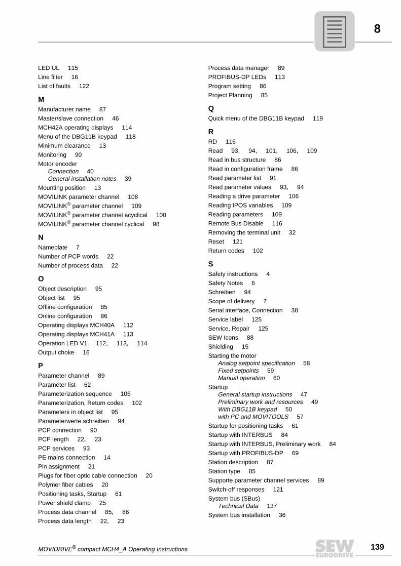
MOVIDRIVE® compact MCH4_A Operating Instructions 139
8
LED UL 115
Line filter 16
List of faults 122
MManufacturer name 87
Master/slave connection 46
MCH42A operating displays 114
Menu of the DBG11B keypad 118
Minimum clearance 13
Monitoring 90
Motor encoderConnection 40General installation notes 39
Mounting position 13
MOVILINK parameter channel 108
MOVILINK® parameter channel 109
MOVILINK® parameter channel acyclical 100
MOVILINK® parameter channel cyclical 98
NNameplate 7Number of PCP words 22
Number of process data 22
OObject description 95
Object list 95
Offline configuration 85
Online configuration 86
Operating displays MCH40A 112
Operating displays MCH41A 113
Operation LED V1 112, 113, 114
Output choke 16
PParameter channel 89
Parameter list 62
Parameterization sequence 105
Parameterization, Return codes 102
Parameters in object list 95
Parameterwerte schreiben 94
PCP connection 90
PCP length 22, 23
PCP services 93
PE mains connection 14
Pin assignment 21
Plugs for fiber optic cable connection 20
Polymer fiber cables 20
Positioning tasks, Startup 61
Power shield clamp 25
Process data channel 85, 86
Process data length 22, 23
Process data manager 89
PROFIBUS-DP LEDs 113
Program setting 86
Project Planning 85
QQuick menu of the DBG11B keypad 119
RRD 116
Read 93, 94, 101, 106, 109
Read in bus structure 86
Read in configuration frame 86
Read parameter list 91
Read parameter values 93, 94
Reading a drive parameter 106
Reading IPOS variables 109
Reading parameters 109
Remote Bus Disable 116
Removing the terminal unit 32
Reset 121
Return codes 102
SSafety instructions 4Safety Notes 6Schreiben 94
Scope of delivery 7Serial interface, Connection 38
Service label 125
Service, Repair 125
SEW Icons 88
Shielding 15
Starting the motorAnalog setpoint specification 58Fixed setpoints 59Manual operation 60
StartupGeneral startup instructions 47Preliminary work and resources 49With DBG11B keypad 50with PC and MOVITOOLS 57
Startup for positioning tasks 61
Startup with INTERBUS 84
Startup with INTERBUS, Preliminary work 84
Startup with PROFIBUS-DP 69
Station description 87
Station type 85
Supporte parameter channel services 89
Switch-off responses 121
System bus (SBus)Technical Data 137
System bus installation 36
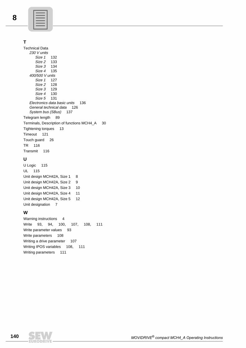
8
140 MOVIDRIVE® compact MCH4_A Operating Instructions
TTechnical Data
230 V unitsSize 1 132Size 2 133Size 3 134Size 4 135
400/500 V unitsSize 1 127Size 2 128Size 3 129Size 4 130Size 5 131
Electronics data basic units 136General technical data 126System bus (SBus) 137
Telegram length 89
Terminals, Description of functions MCH4_A 30
Tightening torques 13
Timeout 121
Touch guard 26
TR 116
Transmit 116
UU Logic 115
UL 115
Unit design MCH42A, Size 1 8Unit design MCH42A, Size 2 9Unit design MCH42A, Size 3 10
Unit design MCH42A, Size 4 11
Unit design MCH42A, Size 5 12
Unit designation 7
WWarning instructions 4Write 93, 94, 100, 107, 108, 111
Write parameter values 93
Write parameters 108
Writing a drive parameter 107
Writing IPOS variables 108, 111
Writing parameters 111
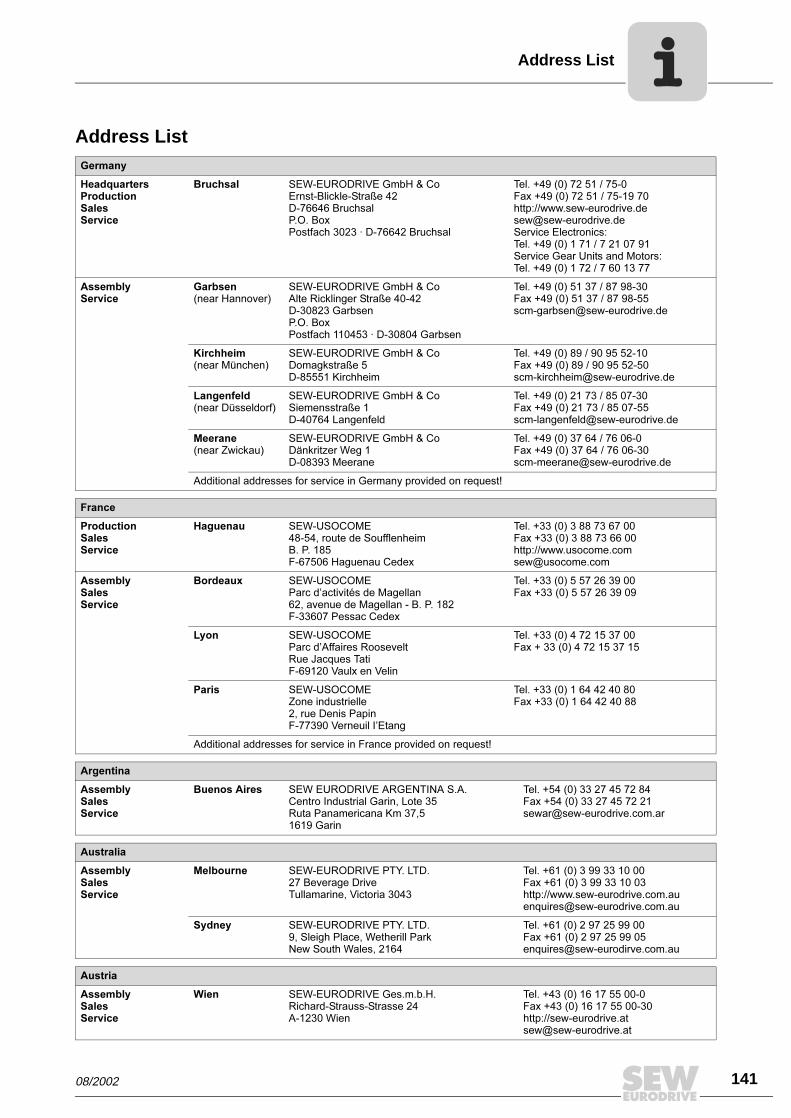
08/2002 141
Address List
Address ListGermany
HeadquartersProductionSalesService
Bruchsal SEW-EURODRIVE GmbH & CoErnst-Blickle-Straße 42 D-76646 BruchsalP.O. BoxPostfach 3023 · D-76642 Bruchsal
Tel. +49 (0) 72 51 / 75-0Fax +49 (0) 72 51 / 75-19 70http://[email protected] Electronics:Tel. +49 (0) 1 71 / 7 21 07 91Service Gear Units and Motors:Tel. +49 (0) 1 72 / 7 60 13 77
AssemblyService
Garbsen (near Hannover)
SEW-EURODRIVE GmbH & CoAlte Ricklinger Straße 40-42 D-30823 GarbsenP.O. BoxPostfach 110453 · D-30804 Garbsen
Tel. +49 (0) 51 37 / 87 98-30Fax +49 (0) 51 37 / 87 [email protected]
Kirchheim (near München)
SEW-EURODRIVE GmbH & CoDomagkstraße 5D-85551 Kirchheim
Tel. +49 (0) 89 / 90 95 52-10Fax +49 (0) 89 / 90 95 [email protected]
Langenfeld (near Düsseldorf)
SEW-EURODRIVE GmbH & CoSiemensstraße 1D-40764 Langenfeld
Tel. +49 (0) 21 73 / 85 07-30Fax +49 (0) 21 73 / 85 [email protected]
Meerane(near Zwickau)
SEW-EURODRIVE GmbH & CoDänkritzer Weg 1D-08393 Meerane
Tel. +49 (0) 37 64 / 76 06-0Fax +49 (0) 37 64 / 76 [email protected]
Additional addresses for service in Germany provided on request!
France
ProductionSalesService
Haguenau SEW-USOCOME 48-54, route de Soufflenheim B. P. 185F-67506 Haguenau Cedex
Tel. +33 (0) 3 88 73 67 00 Fax +33 (0) 3 88 73 66 00http://[email protected]
AssemblySalesService
Bordeaux SEW-USOCOME Parc d’activités de Magellan62, avenue de Magellan - B. P. 182F-33607 Pessac Cedex
Tel. +33 (0) 5 57 26 39 00Fax +33 (0) 5 57 26 39 09
Lyon SEW-USOCOME Parc d’Affaires RooseveltRue Jacques TatiF-69120 Vaulx en Velin
Tel. +33 (0) 4 72 15 37 00Fax + 33 (0) 4 72 15 37 15
Paris SEW-USOCOME Zone industrielle 2, rue Denis Papin F-77390 Verneuil I’Etang
Tel. +33 (0) 1 64 42 40 80Fax +33 (0) 1 64 42 40 88
Additional addresses for service in France provided on request!
Argentina
AssemblySalesService
Buenos Aires SEW EURODRIVE ARGENTINA S.A.Centro Industrial Garin, Lote 35Ruta Panamericana Km 37,51619 Garin
Tel. +54 (0) 33 27 45 72 84Fax +54 (0) 33 27 45 72 [email protected]
Australia
AssemblySalesService
Melbourne SEW-EURODRIVE PTY. LTD.27 Beverage DriveTullamarine, Victoria 3043
Tel. +61 (0) 3 99 33 10 00Fax +61 (0) 3 99 33 10 03http://[email protected]
Sydney SEW-EURODRIVE PTY. LTD.9, Sleigh Place, Wetherill Park New South Wales, 2164
Tel. +61 (0) 2 97 25 99 00Fax +61 (0) 2 97 25 99 [email protected]
Austria
AssemblySalesService
Wien SEW-EURODRIVE Ges.m.b.H. Richard-Strauss-Strasse 24A-1230 Wien
Tel. +43 (0) 16 17 55 00-0Fax +43 (0) 16 17 55 00-30http://[email protected]
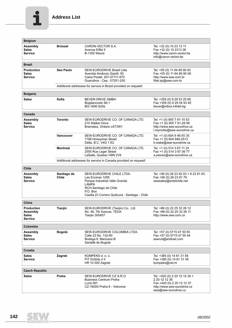
142 08/2002
Address List
Belgium
AssemblySalesService
Brüssel CARON-VECTOR S.A.Avenue Eiffel 5B-1300 Wavre
Tel. +32 (0) 10 23 13 11Fax +32 (0) 10 2313 36http://[email protected]
Brazil
ProductionSalesService
Sao Paulo SEW-EURODRIVE Brasil Ltda.Avenida Amâncio Gaiolli, 50Caixa Postal: 201-07111-970Guarulhos - Cep.: 07251-250
Tel. +55 (0) 11 64 89 90 00Fax +55 (0) 11 64 89 90 09http://[email protected]
Additional addresses for service in Brazil provided on request!
Bulgaria
Sales Sofia BEVER-DRIVE GMBHBogdanovetz Str.1BG-1606 Sofia
Tel. +359 (0) 9 29 53 25 65Fax +359 (0) 9 29 54 93 [email protected]
Canada
AssemblySalesService
Toronto SEW-EURODRIVE CO. OF CANADA LTD. 210 Walker Drive Bramalea, Ontario L6T3W1
Tel. +1 (0) 905 7 91-15 53Fax +1 (0) 905 7 91-29 99http://[email protected]
Vancouver SEW-EURODRIVE CO. OF CANADA LTD.7188 Honeyman Street Delta. B.C. V4G 1 E2
Tel. +1 (0) 604 9 46-55 35Fax +1 (0) 604 [email protected]
Montreal SEW-EURODRIVE CO. OF CANADA LTD.2555 Rue Leger Street LaSalle, Quebec H8N 2V9
Tel. +1 (0) 514 3 67-11 24Fax +1 (0) 514 3 67-36 [email protected]
Additional addresses for service in Canada provided on request!
Chile
AssemblySalesService
Santiago de Chile
SEW-EURODRIVE CHILE LTDA.Las Encinas 1295Parque Industrial Valle GrandeLAMPARCH-Santiago de ChileP.O. BoxCasilla 23 Correro Quilicura - Santiago - Chile
Tel. +56 (0) 26 23 82 03 + 6 23 81 63Fax +56 (0) 26 23 81 [email protected]
China
ProductionAssemblySalesService
Tianjin SEW-EURODRIVE (Tianjin) Co., Ltd.No. 46, 7th Avenue, TEDA Tianjin 300457
Tel. +86 (0) 22 25 32 26 12Fax +86 (0) 22 25 32 26 11http://www.sew.com.cn
Colombia
AssemblySalesService
Bogotá SEW-EURODRIVE COLOMBIA LTDA. Calle 22 No. 132-60Bodega 6, Manzana BSantafé de Bogotá
Tel. +57 (0) 5715 47 50 50Fax +57 (0) 5715 47 50 [email protected]
Croatia
SalesService
Zagreb KOMPEKS d. o. o.PIT Erdödy 4 IIHR 10 000 Zagreb
Tel. +385 (0) 14 61 31 58Fax +385 (0) 14 61 31 [email protected]
Czech Republic
Sales Praha SEW-EURODRIVE CZ S.R.O.Business Centrum Praha Luná 591CZ-16000 Praha 6 - Vokovice
Tel. +420 (0) 2 20 12 12 34 + 2 20 12 12 36Fax +420 (0) 2 20 12 12 37http://[email protected]
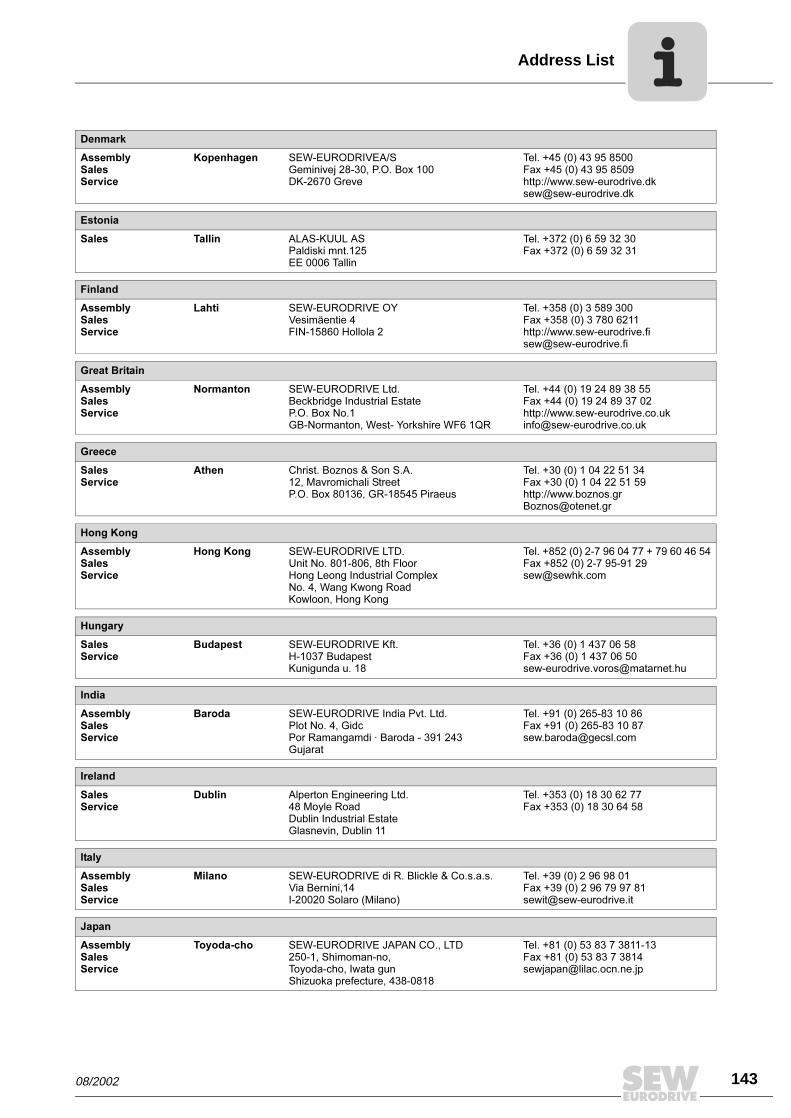
08/2002 143
Address List
Denmark
AssemblySalesService
Kopenhagen SEW-EURODRIVEA/SGeminivej 28-30, P.O. Box 100DK-2670 Greve
Tel. +45 (0) 43 95 8500Fax +45 (0) 43 95 8509http://[email protected]
Estonia
Sales Tallin ALAS-KUUL ASPaldiski mnt.125EE 0006 Tallin
Tel. +372 (0) 6 59 32 30Fax +372 (0) 6 59 32 31
Finland
AssemblySalesService
Lahti SEW-EURODRIVE OYVesimäentie 4FIN-15860 Hollola 2
Tel. +358 (0) 3 589 300Fax +358 (0) 3 780 6211http://[email protected]
Great Britain
AssemblySalesService
Normanton SEW-EURODRIVE Ltd.Beckbridge Industrial Estate P.O. Box No.1GB-Normanton, West- Yorkshire WF6 1QR
Tel. +44 (0) 19 24 89 38 55Fax +44 (0) 19 24 89 37 02http://[email protected]
Greece
SalesService
Athen Christ. Boznos & Son S.A.12, Mavromichali StreetP.O. Box 80136, GR-18545 Piraeus
Tel. +30 (0) 1 04 22 51 34 Fax +30 (0) 1 04 22 51 59http://[email protected]
Hong Kong
AssemblySalesService
Hong Kong SEW-EURODRIVE LTD.Unit No. 801-806, 8th FloorHong Leong Industrial ComplexNo. 4, Wang Kwong Road Kowloon, Hong Kong
Tel. +852 (0) 2-7 96 04 77 + 79 60 46 54Fax +852 (0) 2-7 95-91 [email protected]
Hungary
SalesService
Budapest SEW-EURODRIVE Kft.H-1037 BudapestKunigunda u. 18
Tel. +36 (0) 1 437 06 58Fax +36 (0) 1 437 06 [email protected]
India
AssemblySalesService
Baroda SEW-EURODRIVE India Pvt. Ltd.Plot No. 4, GidcPor Ramangamdi · Baroda - 391 243Gujarat
Tel. +91 (0) 265-83 10 86Fax +91 (0) 265-83 10 [email protected]
Ireland
SalesService
Dublin Alperton Engineering Ltd. 48 Moyle RoadDublin Industrial EstateGlasnevin, Dublin 11
Tel. +353 (0) 18 30 62 77Fax +353 (0) 18 30 64 58
Italy
AssemblySalesService
Milano SEW-EURODRIVE di R. Blickle & Co.s.a.s.Via Bernini,14 I-20020 Solaro (Milano)
Tel. +39 (0) 2 96 98 01Fax +39 (0) 2 96 79 97 [email protected]
Japan
AssemblySalesService
Toyoda-cho SEW-EURODRIVE JAPAN CO., LTD 250-1, Shimoman-no,Toyoda-cho, Iwata gunShizuoka prefecture, 438-0818
Tel. +81 (0) 53 83 7 3811-13Fax +81 (0) 53 83 7 [email protected]
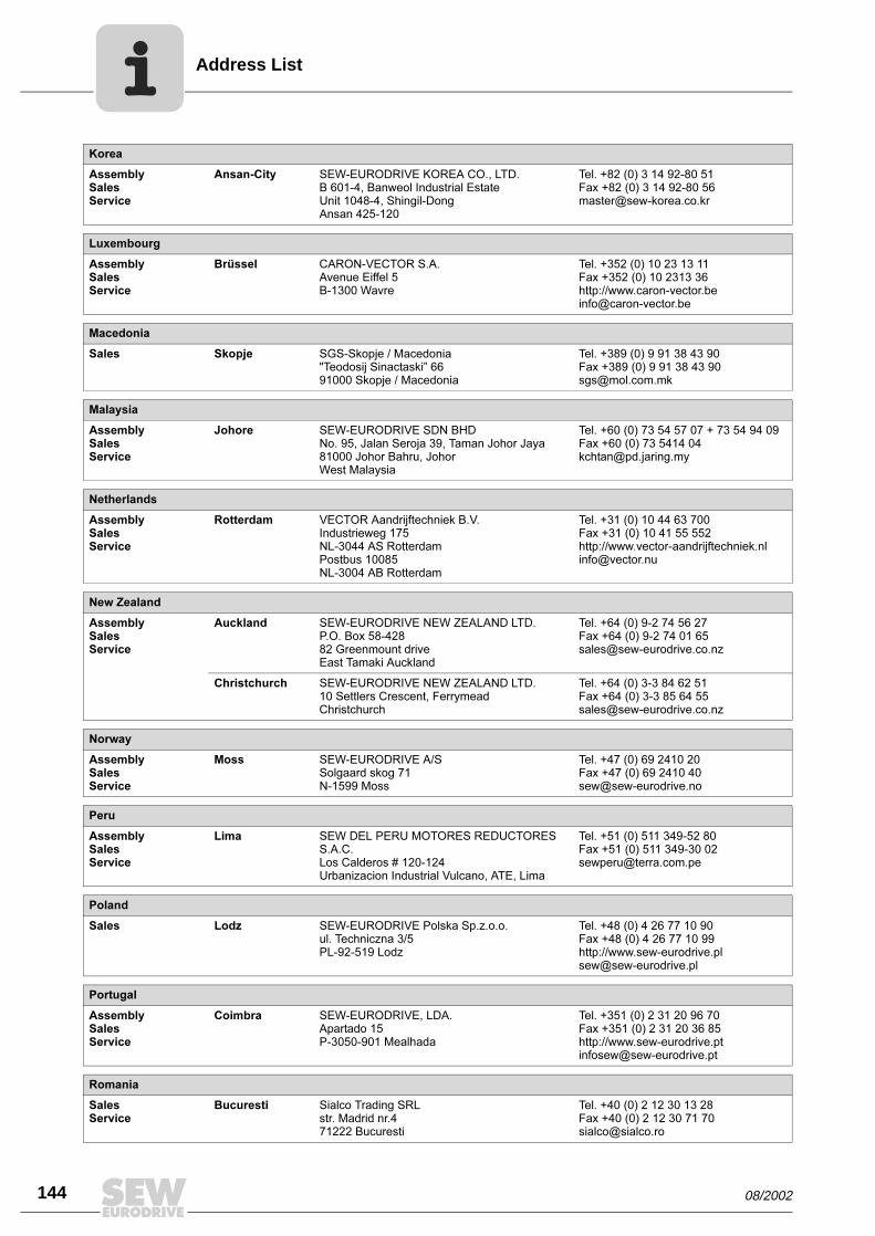
144 08/2002
Address List
Korea
AssemblySalesService
Ansan-City SEW-EURODRIVE KOREA CO., LTD. B 601-4, Banweol Industrial Estate Unit 1048-4, Shingil-DongAnsan 425-120
Tel. +82 (0) 3 14 92-80 51Fax +82 (0) 3 14 92-80 [email protected]
Luxembourg
AssemblySalesService
Brüssel CARON-VECTOR S.A.Avenue Eiffel 5B-1300 Wavre
Tel. +352 (0) 10 23 13 11Fax +352 (0) 10 2313 36http://[email protected]
Macedonia
Sales Skopje SGS-Skopje / Macedonia"Teodosij Sinactaski” 6691000 Skopje / Macedonia
Tel. +389 (0) 9 91 38 43 90Fax +389 (0) 9 91 38 43 [email protected]
Malaysia
AssemblySalesService
Johore SEW-EURODRIVE SDN BHD No. 95, Jalan Seroja 39, Taman Johor Jaya81000 Johor Bahru, JohorWest Malaysia
Tel. +60 (0) 73 54 57 07 + 73 54 94 09Fax +60 (0) 73 5414 [email protected]
Netherlands
AssemblySalesService
Rotterdam VECTOR Aandrijftechniek B.V. Industrieweg 175 NL-3044 AS RotterdamPostbus 10085NL-3004 AB Rotterdam
Tel. +31 (0) 10 44 63 700Fax +31 (0) 10 41 55 552http://[email protected]
New Zealand
AssemblySalesService
Auckland SEW-EURODRIVE NEW ZEALAND LTD. P.O. Box 58-428 82 Greenmount driveEast Tamaki Auckland
Tel. +64 (0) 9-2 74 56 27Fax +64 (0) 9-2 74 01 [email protected]
Christchurch SEW-EURODRIVE NEW ZEALAND LTD. 10 Settlers Crescent, FerrymeadChristchurch
Tel. +64 (0) 3-3 84 62 51Fax +64 (0) 3-3 85 64 [email protected]
Norway
AssemblySalesService
Moss SEW-EURODRIVE A/SSolgaard skog 71N-1599 Moss
Tel. +47 (0) 69 2410 20Fax +47 (0) 69 2410 [email protected]
Peru
AssemblySalesService
Lima SEW DEL PERU MOTORES REDUCTORES S.A.C.Los Calderos # 120-124Urbanizacion Industrial Vulcano, ATE, Lima
Tel. +51 (0) 511 349-52 80Fax +51 (0) 511 349-30 [email protected]
Poland
Sales Lodz SEW-EURODRIVE Polska Sp.z.o.o.ul. Techniczna 3/5 PL-92-519 Lodz
Tel. +48 (0) 4 26 77 10 90Fax +48 (0) 4 26 77 10 99http://[email protected]
Portugal
AssemblySalesService
Coimbra SEW-EURODRIVE, LDA. Apartado 15 P-3050-901 Mealhada
Tel. +351 (0) 2 31 20 96 70Fax +351 (0) 2 31 20 36 85http://[email protected]
Romania
SalesService
Bucuresti Sialco Trading SRL str. Madrid nr.4 71222 Bucuresti
Tel. +40 (0) 2 12 30 13 28Fax +40 (0) 2 12 30 71 70 [email protected]
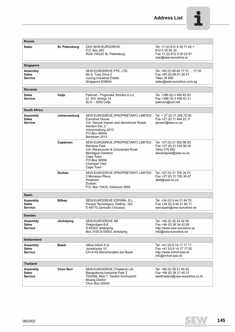
08/2002 145
Address List
Russia
Sales St. Petersburg ZAO SEW-EURODRIVE P.O. Box 263 RUS-195220 St. Petersburg
Tel. +7 (0) 812 5 35 71 42 + 812 5 35 04 30Fax +7 (0) 812 5 35 22 [email protected]
Singapore
AssemblySalesService
SEW-EURODRIVE PTE. LTD. No 9, Tuas Drive 2 Jurong Industrial Estate Singapore 638644
Tel. +65 (0) 68 62 17 01 ... 17 05Fax +65 (0) 68 61 28 27Telex 38 659 [email protected]
Slovenia
SalesService
Celje Pakman - Pogonska Tehnika d.o.o.UI. XIV. divizije 14SLO – 3000 Celje
Tel. +386 (0) 3 490 83 20Fax +386 (0) 3 490 83 [email protected]
South Africa
AssemblySalesService
Johannesburg SEW-EURODRIVE (PROPRIETARY) LIMITEDEurodrive House Cnr. Adcock Ingram and Aerodrome RoadsAeroton Ext. 2Johannesburg 2013P.O.Box 90004Bertsham 2013
Tel. + 27 (0) 11 248 70 00Fax +27 (0) 11 494 23 [email protected]
Capetown SEW-EURODRIVE (PROPRIETARY) LIMITED Rainbow ParkCnr. Racecourse & Omuramba RoadMontague GardensCape TownP.O.Box 36556Chempet 7442 Cape Town
Tel. +27 (0) 21 552 98 20Fax +27 (0) 21 552 98 30Telex 576 [email protected]
Durban SEW-EURODRIVE (PROPRIETARY) LIMITED2 Monaceo PlacePinetownDurbanP.O. Box 10433, Ashwood 3605
Tel. +27 (0) 31 700 34 51Fax +27 (0) 31 700 38 [email protected]
Spain
AssemblySalesService
Bilbao SEW-EURODRIVE ESPAÑA, S.L. Parque Tecnológico, Edificio, 302E-48170 Zamudio (Vizcaya)
Tel. +34 (0) 9 44 31 84 70Fax +34 (0) 9 44 31 84 [email protected]
Sweden
AssemblySalesService
Jönköping SEW-EURODRIVE ABGnejsvägen 6-8S-55303 JönköpingBox 3100 S-55003 Jönköping
Tel. +46 (0) 36 34 42 00Fax +46 (0) 36 34 42 80http://[email protected]
Switzerland
AssemblySalesService
Basel Alfred lmhof A.G.Jurastrasse 10 CH-4142 Münchenstein bei Basel
Tel. +41 (0) 6 14 17 17 17Fax +41 (0) 6 14 17 17 00http://[email protected]
Thailand
AssemblySalesService
Chon Buri SEW-EURODRIVE (Thailand) Ltd.Bangpakong Industrial Park 2700/456, Moo.7, Tambol DonhuarohMuang DistrictChon Buri 20000
Tel. +66 (0) 38 21 40 22Fax +66 (0) 38 21 45 [email protected]
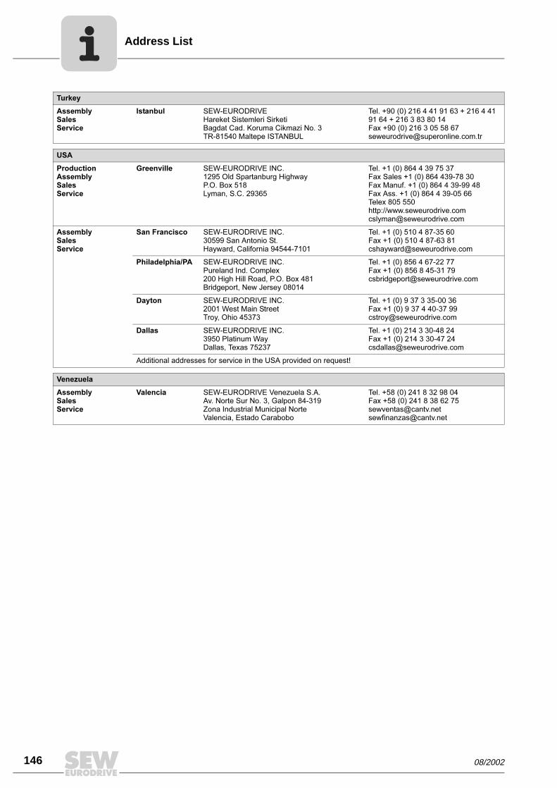
146 08/2002
Address List
Turkey
AssemblySalesService
Istanbul SEW-EURODRIVE Hareket Sistemleri Sirketi Bagdat Cad. Koruma Cikmazi No. 3 TR-81540 Maltepe ISTANBUL
Tel. +90 (0) 216 4 41 91 63 + 216 4 41 91 64 + 216 3 83 80 14Fax +90 (0) 216 3 05 58 [email protected]
USA
ProductionAssemblySalesService
Greenville SEW-EURODRIVE INC. 1295 Old Spartanburg Highway P.O. Box 518Lyman, S.C. 29365
Tel. +1 (0) 864 4 39 75 37Fax Sales +1 (0) 864 439-78 30Fax Manuf. +1 (0) 864 4 39-99 48Fax Ass. +1 (0) 864 4 39-05 66Telex 805 550 http://[email protected]
AssemblySalesService
San Francisco SEW-EURODRIVE INC. 30599 San Antonio St.Hayward, California 94544-7101
Tel. +1 (0) 510 4 87-35 60Fax +1 (0) 510 4 87-63 [email protected]
Philadelphia/PA SEW-EURODRIVE INC. Pureland Ind. Complex 200 High Hill Road, P.O. Box 481Bridgeport, New Jersey 08014
Tel. +1 (0) 856 4 67-22 77Fax +1 (0) 856 8 45-31 [email protected]
Dayton SEW-EURODRIVE INC.2001 West Main Street Troy, Ohio 45373
Tel. +1 (0) 9 37 3 35-00 36Fax +1 (0) 9 37 4 40-37 [email protected]
Dallas SEW-EURODRIVE INC.3950 Platinum Way Dallas, Texas 75237
Tel. +1 (0) 214 3 30-48 24Fax +1 (0) 214 3 30-47 [email protected]
Additional addresses for service in the USA provided on request!
Venezuela
AssemblySalesService
Valencia SEW-EURODRIVE Venezuela S.A.Av. Norte Sur No. 3, Galpon 84-319Zona Industrial Municipal NorteValencia, Estado Carabobo
Tel. +58 (0) 241 8 32 98 04Fax +58 (0) 241 8 38 62 [email protected]@cantv.net


SEW-EURODRIVE GmbH & Co · P.O. Box 3023 · D-76642 Bruchsal/Germany · Phone +49-7251-75-0Fax +49-7251-75-1970 · http://www.sew-eurodrive.com · [email protected]