Embed Size (px)
Citation preview
Aseptic DrivesEdition
11/2003
Operating Instructions11225912 / EN
SEW-EURODRIVE
Contents
Operating Instructions – Aseptic Drives 3
1 Important Notes................................................................................................. 4
2 Safety Notes ...................................................................................................... 5
3 Motor design...................................................................................................... 73.1 Basic design of the aseptic motor ............................................................. 73.2 Nameplate, unit designation ..................................................................... 8
4 Mechanical Installation..................................................................................... 94.1 Before you begin....................................................................................... 94.2 Preliminary work ....................................................................................... 94.3 Installing the motor.................................................................................. 104.4 Installation tolerances ............................................................................. 10
5 Electrical Installation ...................................................................................... 115.1 Wiring notes ............................................................................................ 115.2 Special aspects for operation with a frequency inverter ......................... 115.3 Special aspects in switching operation ................................................... 115.4 Connecting the motor using the IS plug connector ................................. 125.5 Connecting the brake.............................................................................. 175.6 Accessory equipment.............................................................................. 17
6 Startup.............................................................................................................. 186.1 Prerequisites for startup.......................................................................... 18
7 Malfunctions .................................................................................................... 197.1 Motor problems ....................................................................................... 197.2 Brake problems....................................................................................... 207.3 Malfunctions when operating with a frequency inverter .......................... 20
8 Inspection / Maintenance ............................................................................... 218.1 Inspection and maintenance intervals..................................................... 218.2 Inspection and maintenance of the brake BR ........................................ 22
9 Technical Data................................................................................................. 249.1 Braking torques BR1, BR2...................................................................... 249.2 Operating currents .................................................................................. 249.3 Gear unit gaskets/seals .......................................................................... 259.4 Motor gaskets/seals ................................................................................ 259.5 Permitted ball bearing types ................................................................... 259.6 Lubricant table for anti-friction bearings of SEW motors......................... 25
10 Index................................................................................................................. 26
4
1 mportant Notes
1 Important NotesSafety and warning instructions
Always observe the safety and warning instructions in this publication!
A requirement of fault-free operation and fulfillment of any rights to claim underguarantee is that the information in the operating instructions is adhered to.Consequently, read the operating instructions before you start operating the drive!
The operating instructions contain important information about servicing and should bekept close to the unit.
Waste disposal This product consists of:
• Iron
• Aluminum
• Copper
• Plastic
• Electronic components
Please dispose of the parts in accordance with the applicable regulations.
Electrical hazardPossible consequences: Severe or fatal injuries.
Hazard Possible consequences: Severe or fatal injuries.
Hazardous situationPossible consequences: Slight or minor injuries.
Harmful situationPossible consequences: Damage to the drive and the environment.
Tips and useful information.
I
Operating Instructions – Aseptic Drives
2Safety Notes
2 Safety NotesPreliminary remarks
The following safety notes are concerned with the use of motors. If using gearmotors,also refer to the safety notes for gear units in the corresponding operating instructions.
Please also observe the supplementary safety notes in the individual sections ofthese operating instructions.
General information
During and after operation, motors and gearmotors have live and moving parts and theirsurfaces may be hot.
All work related to transport, putting into storage, setting up/mounting,connection, startup, maintenance and repair may only be performed by trainedpersonnel observing
• the corresponding detailed operating instruction(s) and wiring diagrams,
• the warning and safety signs on the motor/gearmotor,
• the specific regulations and requirements for the system and
• national/regional regulations governing safety and the prevention of accidents.
Severe injuries and damage to property may result from
• incorrect use,
• incorrect installation or operation,
• removal of required protective covers or the housing when this is not permitted.
Designated use These electric motors are intended for industrial systems. They comply with theapplicable standards and regulations and meet the requirements of the Low VoltageDirective 73/23/EEC.
The technical data and the information about permitted conditions are to be found on thenameplate and in the documentation.
When using cleaning agents, ensure that they are compatible with the sealingcompounds listed in section 9.
It is essential to observe all specified information!
Operating Instructions – Aseptic Drives
5
2
6
afety Notes
Transportation Inspect the shipment for any damage in transit as soon as you receive thedelivery. Inform the shipping company immediately. It may be necessary topreclude startup.
Tighten installed transportation lugs. They are only rated for the weight of the motor/gearmotor; do not attach any additional loads.
The installed lifting eyebolts comply with DIN 580. The loads and regulationsspecified in that document must always be observed. If the gearmotor is equippedwith two suspension eye lugs or lifting eyebolts, then both of the suspension eyelugs should be used for transportation. In this case, the tension force vector ofthe slings must not exceed a 45° angle in accordance with DIN 580.
Use suitable, sufficiently rated handling equipment if necessary. Remove anytransportation fixtures prior to startup.
Installation / mounting
Follow the instructions in the section "Mechanical Installation"!
Inspection / maintenance
Follow the instructions in the section "Inspection and maintenance"!
S
Operating Instructions – Aseptic Drives
3Basic design of the aseptic motorMotor design
3 Motor design
3.1 Basic design of the aseptic motor
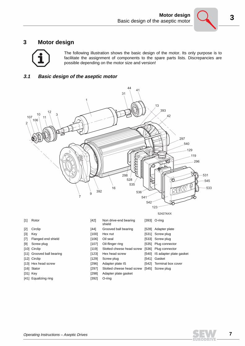
The following illustration shows the basic design of the motor. Its only purpose is tofacilitate the assignment of components to the spare parts lists. Discrepancies arepossible depending on the motor size and version!
52427AXX
[1] Rotor [42] Non drive-end bearing shield
[393] O-ring
[2] Circlip [44] Grooved ball bearing [528] Adapter plate
[3] Key [100] Hex nut [531] Screw plug
[7] Flanged end shield [106] Oil seal [533] Screw plug
[9] Screw plug [107] Oil-flinger ring [535] Plug connector
[10] Circlip [119] Slotted cheese head screw [536] Plug connector
[11] Grooved ball bearing [123] Hex head screw [540] IS adapter plate gasket
[12] Circlip [129] Screw plug [541] Gasket
[13] Hex head screw [296] Adapter plate IS [542] Terminal box cover
[16] Stator [297] Slotted cheese head screw [545] Screw plug
[31] Key [298] Adapter plate gasket
[41] Equalizing ring [392] O-ring
2
107106
1011
123
1
31
4441
13
393
42
297
540
129
119
296
531
545
533
123
542
541
536
535
528
298
39216
97
Operating Instructions – Aseptic Drives
7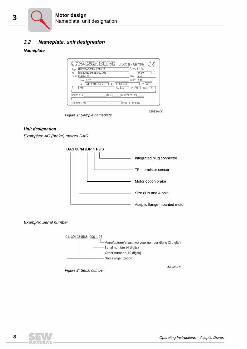
8
3 ameplate, unit designationotor design
3.2 Nameplate, unit designation
Nameplate
Unit designation
Examples: AC (brake) motors DAS
Example: Serial number
52633AXXFigure 1: Sample nameplate
02.3001234568.0001.03R47 DAS80N4 / TF / IS
0,37
1440 / 56
M1
24.99
130
0.76
1.65 / 0.95
66 20
50
F
230 / 400 / Y∆
DAS 80N4 /BR /TF /IS
Integrated plug connector
TF thermistor sensor
Motor option brake
Size 80N and 4-pole
Aseptic flange-mounted motor
06610AENFigure 2: Serial number
01. 301234568. 0001. 03
Manufacturer’s last two year number digits (2 digits)
Serial number (4 digits)
Order number (10 digits)
Sales organization
NM
Operating Instructions – Aseptic Drives
4Before you beginMechanical Installation
4 Mechanical Installation
4.1 Before you begin
The drive may only be installed if
• the entries on the nameplate of the drive and/or the output voltage of the frequencyinverter match the voltage supply system,
• the drive is undamaged (no damage caused by transportation or storage),
• it is certain that the following requirements have been met:
– Ambient temperature between –25 °C and +40 °C,1)
– Installation altitude max. 1000 m above sea level.
4.2 Preliminary work
Motor shaft ends must be thoroughly cleaned of anti-corrosion agents, contamination orsuch like (use a commercially available solvent). Do not allow the solvent to penetratethe bearings or shaft seals – this could cause material damage!
Extended stor-age of motors
• Please note the reduced grease utilization period of the ball bearings after storageperiods exceeding one year.
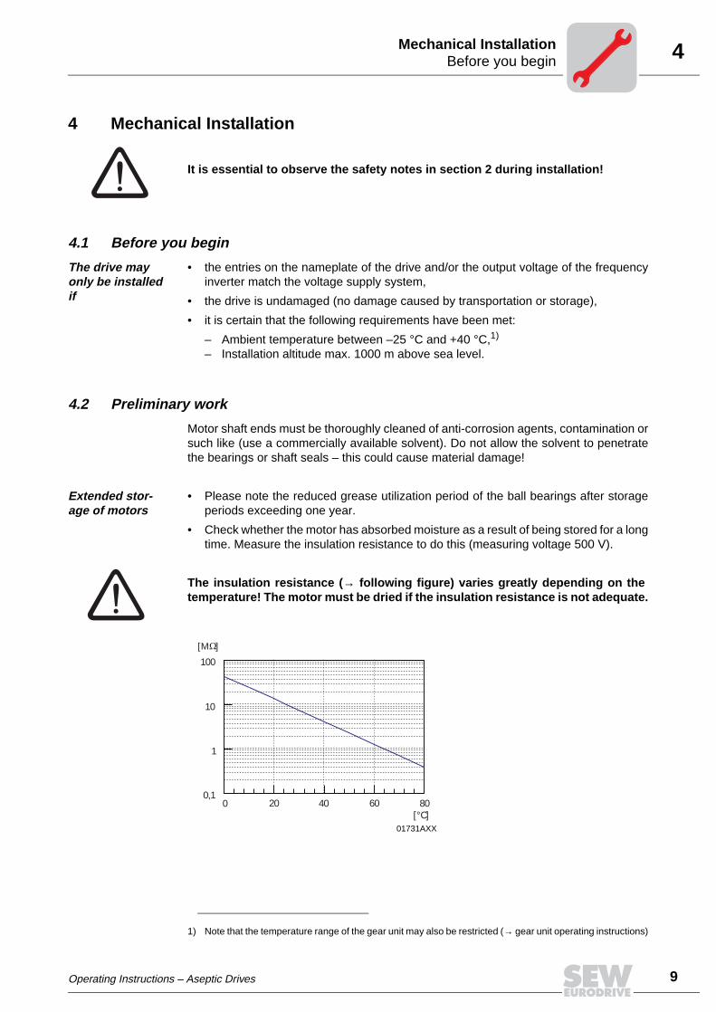
• Check whether the motor has absorbed moisture as a result of being stored for a longtime. Measure the insulation resistance to do this (measuring voltage 500 V).
The insulation resistance (→ following figure) varies greatly depending on thetemperature! The motor must be dried if the insulation resistance is not adequate.
It is essential to observe the safety notes in section 2 during installation!
1) Note that the temperature range of the gear unit may also be restricted (→ gear unit operating instructions)
01731AXX
100
10
1
0,10 20 40 60 80
[°C]
[M ]
Operating Instructions – Aseptic Drives
9
10
4 nstalling the motorechanical Installation
4.3 Installing the motor
The motor or gearmotor may only be mounted or installed in the specified mountingposition on a level and torsionally rigid support structure that is not subject to shocks.
Carefully align the motor and the driven machine to avoid placing any unacceptablestrain on the output shafts (observe permitted overhung load and axial load!).
Do not butt or hammer the shaft end.
Ensure an unobstructed cooling air supply.
Balance components for subsequent mounting on the shaft with a half key (motor shaftsare balanced with a half key).
Installation in damp locations or in the open
If possible, arrange the terminal box so the cable entries are pointing downwards.
Coat the threads of cable glands and pocket caps with sealant and tighten them well.
Seal the cable entry well.
Thoroughly clean the sealing surfaces of terminal boxes and terminal box covers priorto reassembly; gaskets must be glued in on one side. Install new gaskets to replaceembrittled ones!
Restore the anticorrosive coating if necessary.
4.4 Installation tolerances
Shaft end Flanges
Diameter tolerance in accordance with DIN 748• ISO k6 at Ø ≤ 50 mm• ISO m6 at Ø > 50 mm• Center bore in accordance with DIN 332, shape
DR..
Centering shoulder tolerance in accordance with DIN 42948• ISO j6 at Ø ≤ 230 mm• ISO h6 at Ø > 230 mm
IM
Operating Instructions – Aseptic Drives
5Wiring notesElectrical Installation
5 Electrical InstallationIt is essential to comply with the safety notes in section 2 during installation!
Switch contacts in utilization category AC-3 to EN 60947-4-1 must be used forswitching the motor and the brake.
5.1 Wiring notes
Comply with the safety notes during installation.
Protection against interfer-ence from brake control systems
Do not route brake cables alongside switched-mode power cables, since otherwisethere is a risk of disrupting brake controllers.
Switched-mode power cables include in particular:
– Output cables from frequency and servo controllers, soft start units and brake units
– Connecting harnesses to braking resistors, etc.
Protection against interfer-ence from motor protection devices
To provide protection against interference from SEW motor protection devices(temperature sensors TF):
– Route separately shielded feeder cables together with switched-mode power lines inone cable.
– Do not route unshielded feeder cables together with switched-mode power lines inone cable.
5.2 Special aspects for operation with a frequency inverter
When motors are powered from inverters, you must adhere to the wiring instructionsissued by the inverter manufacturer. It is essential to observe the operating instructionsfor the frequency inverter.
5.3 Special aspects in switching operation
When the motors are used in switching operation, any possible malfunctions of theswitchgear must be excluded by appropriate wiring. According to EN 60204 (electricalequipment of machines), motor windings must have interference suppression to protectthe numerical or programmable logic controllers. Since it is primarily switchingoperations that lead to the disruptions, we recommend installing protective circuitry onthe switching devices.
Operating Instructions – Aseptic Drives
11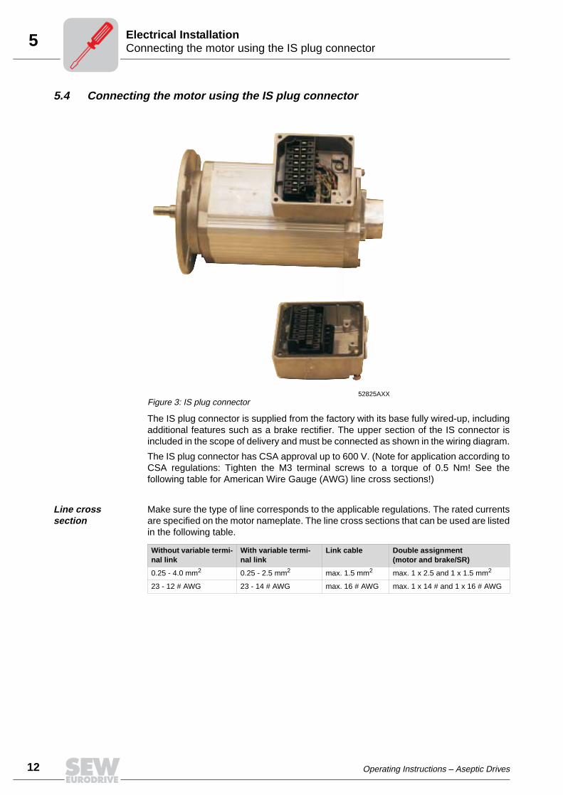
12
5 onnecting the motor using the IS plug connectorlectrical Installation
5.4 Connecting the motor using the IS plug connector
The IS plug connector is supplied from the factory with its base fully wired-up, includingadditional features such as a brake rectifier. The upper section of the IS connector isincluded in the scope of delivery and must be connected as shown in the wiring diagram.
The IS plug connector has CSA approval up to 600 V. (Note for application according toCSA regulations: Tighten the M3 terminal screws to a torque of 0.5 Nm! See thefollowing table for American Wire Gauge (AWG) line cross sections!)
Line cross section
Make sure the type of line corresponds to the applicable regulations. The rated currentsare specified on the motor nameplate. The line cross sections that can be used are listedin the following table.
52825AXXFigure 3: IS plug connector
Without variable termi-nal link
With variable termi-nal link
Link cable Double assignment(motor and brake/SR)
0.25 - 4.0 mm2 0.25 - 2.5 mm2 max. 1.5 mm2 max. 1 x 2.5 and 1 x 1.5 mm2
23 - 12 # AWG 23 - 14 # AWG max. 16 # AWG max. 1 x 14 # and 1 x 16 # AWG
CE
Operating Instructions – Aseptic Drives
5Connecting the motor using the IS plug connectorElectrical Installation
Wiring the upper section of the plug connection
• Loosen the housing cover screws
– Remove the housing cover
• Remove the screws from the upper section of the plug connector
– Remove the upper section of the plug connector from the cover
• Strip the insulation off the connection lead
– Strip about 9 mm insulation off the connecting leads
• Pass the cable through the cable gland
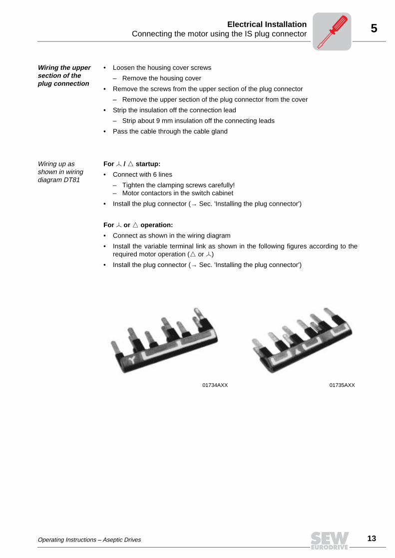
Wiring up as shown in wiring diagram DT81
For / startup:
• Connect with 6 lines
– Tighten the clamping screws carefully!– Motor contactors in the switch cabinet
• Install the plug connector (→ Sec. 'Installing the plug connector')
For or operation:
• Connect as shown in the wiring diagram
• Install the variable terminal link as shown in the following figures according to therequired motor operation ( or )
• Install the plug connector (→ Sec. 'Installing the plug connector')
01734AXX 01735AXX
Operating Instructions – Aseptic Drives
13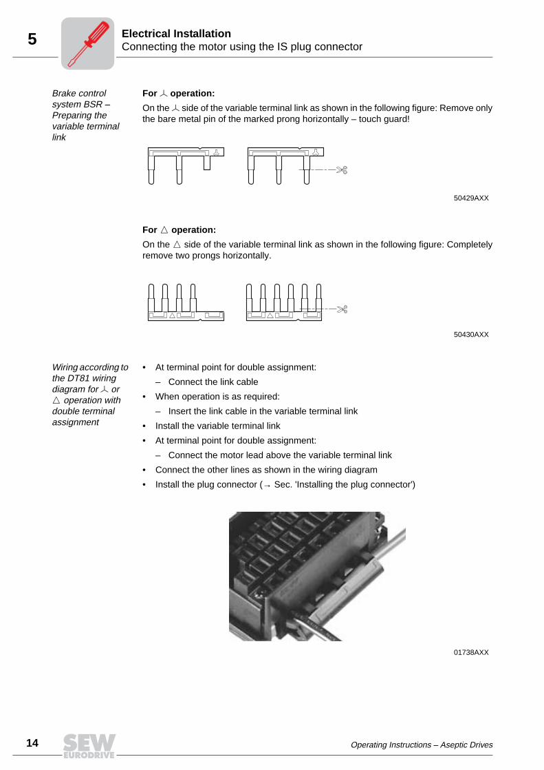
14
5 onnecting the motor using the IS plug connectorlectrical Installation
Brake control system BSR – Preparing the variable terminal link
For operation:
On the side of the variable terminal link as shown in the following figure: Remove onlythe bare metal pin of the marked prong horizontally – touch guard!
For operation:
On the side of the variable terminal link as shown in the following figure: Completelyremove two prongs horizontally.
Wiring according to the DT81 wiring diagram for or operation with double terminal assignment
• At terminal point for double assignment:
– Connect the link cable
• When operation is as required:
– Insert the link cable in the variable terminal link
• Install the variable terminal link
• At terminal point for double assignment:
– Connect the motor lead above the variable terminal link
• Connect the other lines as shown in the wiring diagram
• Install the plug connector (→ Sec. 'Installing the plug connector')
50429AXX
50430AXX
01738AXX
CE
Operating Instructions – Aseptic Drives
5Connecting the motor using the IS plug connectorElectrical Installation
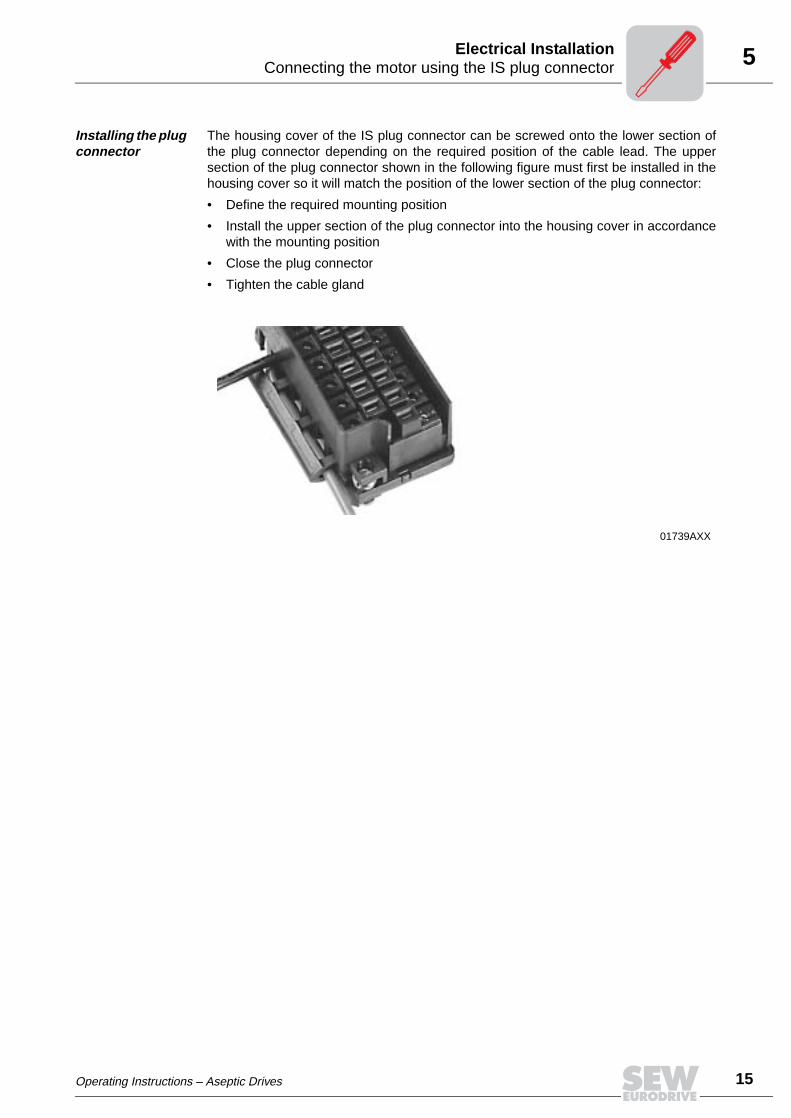
Installing the plug connector
The housing cover of the IS plug connector can be screwed onto the lower section ofthe plug connector depending on the required position of the cable lead. The uppersection of the plug connector shown in the following figure must first be installed in thehousing cover so it will match the position of the lower section of the plug connector:
• Define the required mounting position
• Install the upper section of the plug connector into the housing cover in accordancewith the mounting position
• Close the plug connector
• Tighten the cable gland
01739AXX
Operating Instructions – Aseptic Drives
15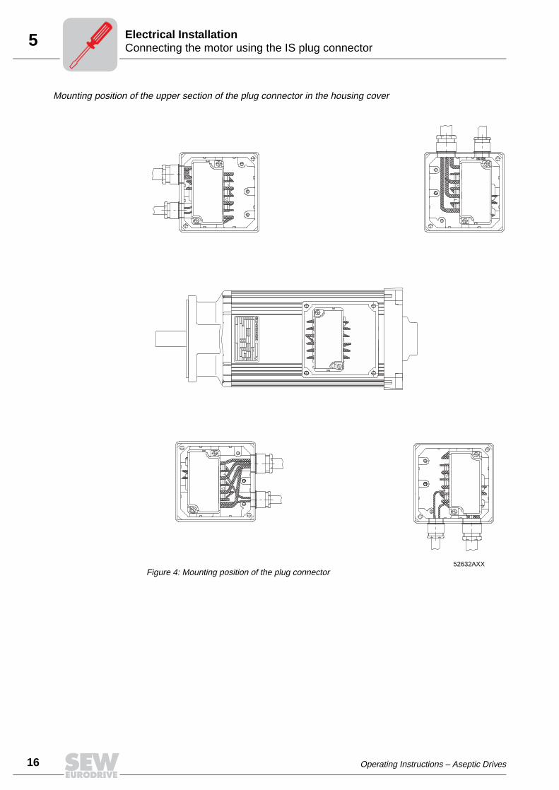
16
5 onnecting the motor using the IS plug connectorlectrical Installation
Mounting position of the upper section of the plug connector in the housing cover
52632AXXFigure 4: Mounting position of the plug connector
CE
Operating Instructions – Aseptic Drives
5Connecting the brakeElectrical Installation
5.5 Connecting the brake
The brake is released electrically. The brake is applied mechanically when the voltageis switched off.
• Connect the brake according to the wiring diagram supplied with the brake.
• Note: In view of the DC voltage to be switched and the high level of current load, itis essential to use either special brake contactors or AC contactors with contacts inutilization category AC-3 to EN 60947-4-1.
• After replacing the brake disc, the maximum braking torque is reached only afterseveral cycle times.
Connecting the brake control system
The DC disk brake is powered from a brake control system with a protection circuit. Thiscontrol is accommodated in the terminal box / IS lower part or must be installed in theswitch cabinet (→ Sec. 'Wiring notes').
• Check the line cross sections - braking currents (→ Sec. 'Technical Data')
• Connect the brake control system according to the wiring diagram supplied with thebrake
5.6 Accessory equipment
Connect supplied accessory equipment according to the wiring diagrams included.
Temperature sensor TF
The positive temperature coefficient (PTC) thermistors comply with DIN 44082.
Resistance measurement (measuring instrument with V ≤ 2.5 V or I < 1 mA):
• Standard measured values: 20...500 Ω, thermal resistance > 4000 Ω
Comply with the applicable regulations issued by the relevant employer’s liabilityinsurance association regarding phase failure protection and the associatedcircuit/circuit modification!
Do not apply any voltage!
Operating Instructions – Aseptic Drives
17
18
6 rerequisites for startuptartup
6 Startup6.1 Prerequisites for startup
Before startup, make sure that
• the drive is undamaged and not blocked,
• the measures stipulated in the "Preliminary work" section are performed afterextended storage,
• all connections have been made properly,
• the direction of rotation of the motor/gearmotor is correct,
– (motor rotating clockwise: U, V, W to L1, L2, L3),
• all protective covers have been installed correctly,
• all motor protection equipment is active and set for the rated motor current,
• there are no other sources of danger present.
During startup, make sure that
• the motor is running correctly (no overload, no speed fluctuation, no loud noises,etc.),
• the correct braking torque is set according to the specific application (→Sec. "Tech-nical Data"),
• in case of problems (→ Sec. "Malfunctions").
It is essential to comply with the safety notes in section 2 during startup!
PS
00
I
Operating Instructions – Aseptic Drives
7Motor problemsMalfunctions
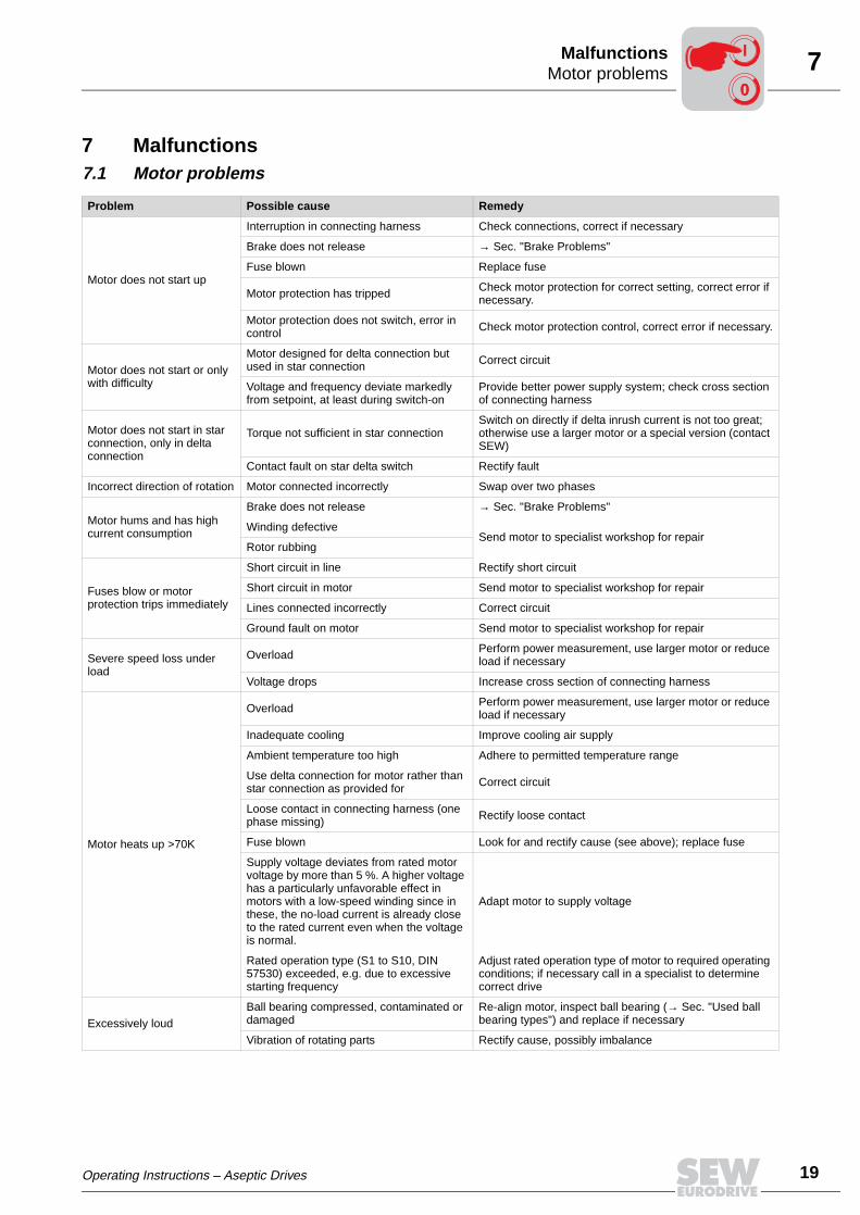
7 Malfunctions7.1 Motor problems
Problem Possible cause Remedy
Motor does not start up
Interruption in connecting harness Check connections, correct if necessary
Brake does not release → Sec. "Brake Problems"
Fuse blown Replace fuse
Motor protection has tripped Check motor protection for correct setting, correct error if necessary.
Motor protection does not switch, error in control Check motor protection control, correct error if necessary.
Motor does not start or only with difficulty
Motor designed for delta connection but used in star connection Correct circuit
Voltage and frequency deviate markedly from setpoint, at least during switch-on
Provide better power supply system; check cross section of connecting harness
Motor does not start in star connection, only in delta connection
Torque not sufficient in star connectionSwitch on directly if delta inrush current is not too great; otherwise use a larger motor or a special version (contact SEW)
Contact fault on star delta switch Rectify fault
Incorrect direction of rotation Motor connected incorrectly Swap over two phases
Motor hums and has high current consumption
Brake does not release → Sec. "Brake Problems"
Winding defectiveSend motor to specialist workshop for repair
Rotor rubbing
Fuses blow or motor protection trips immediately
Short circuit in line Rectify short circuit
Short circuit in motor Send motor to specialist workshop for repair
Lines connected incorrectly Correct circuit
Ground fault on motor Send motor to specialist workshop for repair
Severe speed loss under load
Overload Perform power measurement, use larger motor or reduce load if necessary
Voltage drops Increase cross section of connecting harness
Motor heats up >70K
Overload Perform power measurement, use larger motor or reduce load if necessary
Inadequate cooling Improve cooling air supply
Ambient temperature too high Adhere to permitted temperature range
Use delta connection for motor rather than star connection as provided for Correct circuit
Loose contact in connecting harness (one phase missing) Rectify loose contact
Fuse blown Look for and rectify cause (see above); replace fuse
Supply voltage deviates from rated motor voltage by more than 5 %. A higher voltage has a particularly unfavorable effect in motors with a low-speed winding since in these, the no-load current is already close to the rated current even when the voltage is normal.
Adapt motor to supply voltage
Rated operation type (S1 to S10, DIN 57530) exceeded, e.g. due to excessive starting frequency
Adjust rated operation type of motor to required operating conditions; if necessary call in a specialist to determine correct drive
Excessively loudBall bearing compressed, contaminated or damaged
Re-align motor, inspect ball bearing (→ Sec. "Used ball bearing types") and replace if necessary
Vibration of rotating parts Rectify cause, possibly imbalance
Operating Instructions – Aseptic Drives
00
I
19
20
7 rake problemsalfunctions
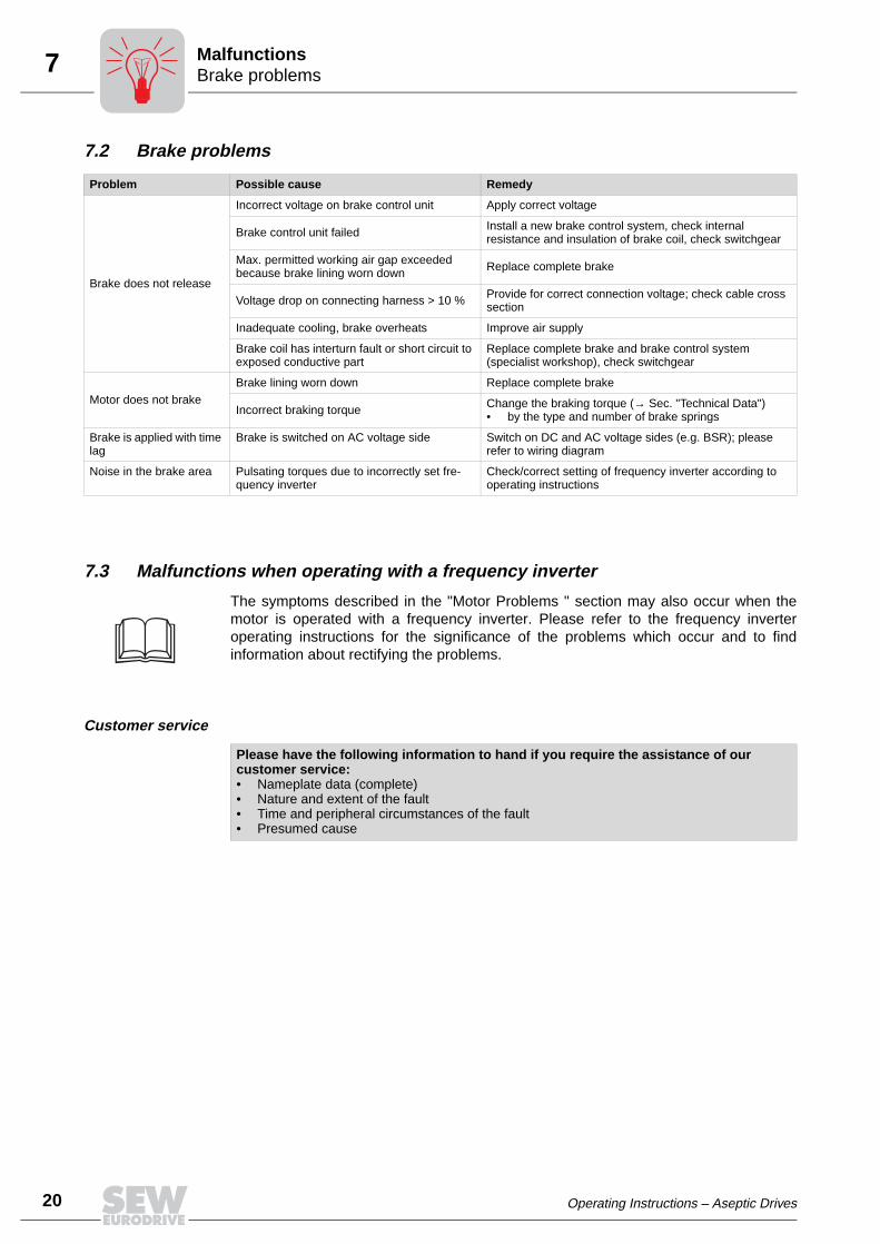
7.2 Brake problems
7.3 Malfunctions when operating with a frequency inverter
The symptoms described in the "Motor Problems " section may also occur when themotor is operated with a frequency inverter. Please refer to the frequency inverteroperating instructions for the significance of the problems which occur and to findinformation about rectifying the problems.
Customer service
Problem Possible cause Remedy
Brake does not release
Incorrect voltage on brake control unit Apply correct voltage
Brake control unit failed Install a new brake control system, check internal resistance and insulation of brake coil, check switchgear
Max. permitted working air gap exceeded because brake lining worn down Replace complete brake
Voltage drop on connecting harness > 10 % Provide for correct connection voltage; check cable cross section
Inadequate cooling, brake overheats Improve air supply
Brake coil has interturn fault or short circuit to exposed conductive part
Replace complete brake and brake control system (specialist workshop), check switchgear
Motor does not brakeBrake lining worn down Replace complete brake
Incorrect braking torque Change the braking torque (→ Sec. "Technical Data")• by the type and number of brake springs
Brake is applied with time lag
Brake is switched on AC voltage side Switch on DC and AC voltage sides (e.g. BSR); please refer to wiring diagram
Noise in the brake area Pulsating torques due to incorrectly set fre-quency inverter
Check/correct setting of frequency inverter according to operating instructions
Please have the following information to hand if you require the assistance of our customer service:• Nameplate data (complete)• Nature and extent of the fault• Time and peripheral circumstances of the fault• Presumed cause
BM
Operating Instructions – Aseptic Drives
8Inspection and maintenance intervalsInspection / Maintenance
8 Inspection / Maintenance• Use only genuine spare parts in accordance with the valid parts list!
• Motors can become very hot during operation – danger of burns!
• Isolate the motor and brake from the power supply before starting work,safeguarding them against unintentional power-up!
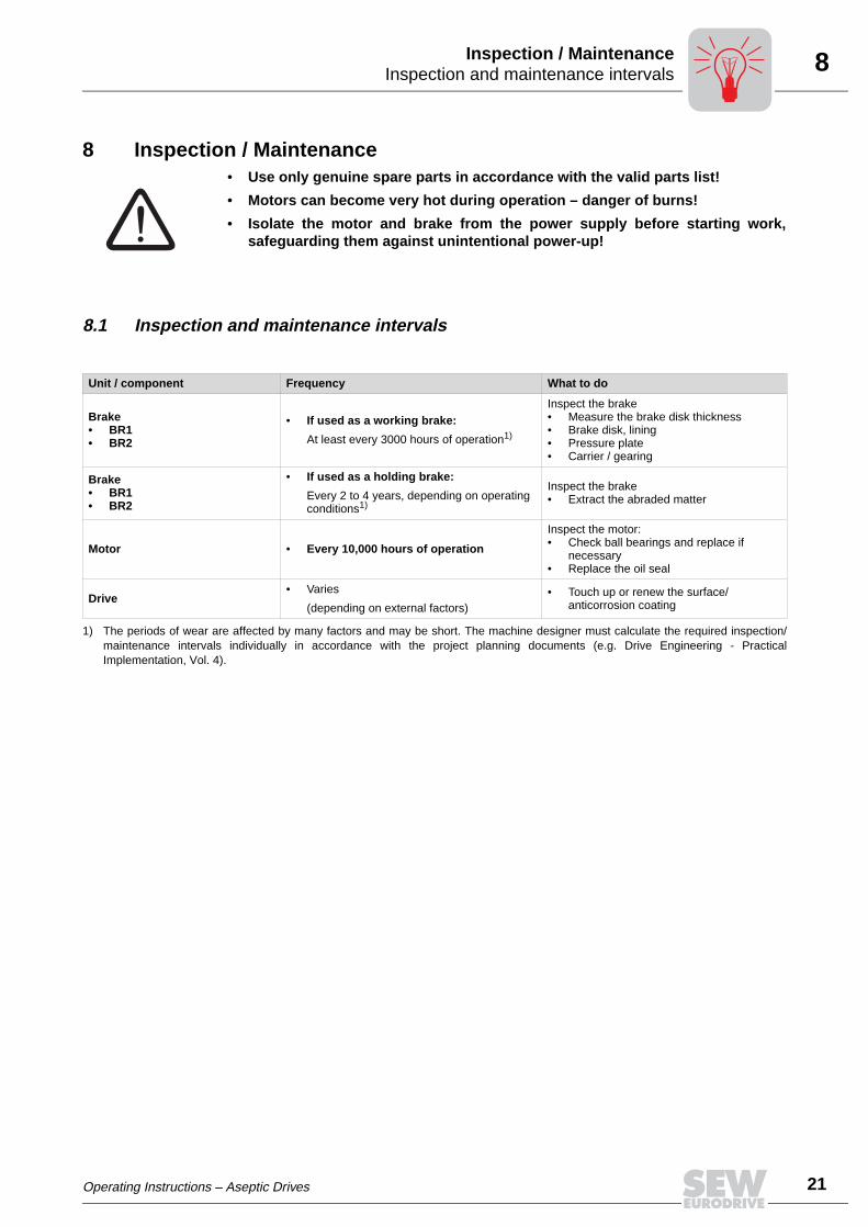
8.1 Inspection and maintenance intervals
Unit / component Frequency What to do
Brake• BR1• BR2
• If used as a working brake:
At least every 3000 hours of operation1)
Inspect the brake• Measure the brake disk thickness• Brake disk, lining• Pressure plate• Carrier / gearing
Brake• BR1• BR2
• If used as a holding brake:
Every 2 to 4 years, depending on operating conditions1)
Inspect the brake• Extract the abraded matter
Motor • Every 10,000 hours of operation
Inspect the motor:• Check ball bearings and replace if
necessary• Replace the oil seal
Drive• Varies
(depending on external factors)• Touch up or renew the surface/
anticorrosion coating
1) The periods of wear are affected by many factors and may be short. The machine designer must calculate the required inspection/maintenance intervals individually in accordance with the project planning documents (e.g. Drive Engineering - PracticalImplementation, Vol. 4).
Operating Instructions – Aseptic Drives
21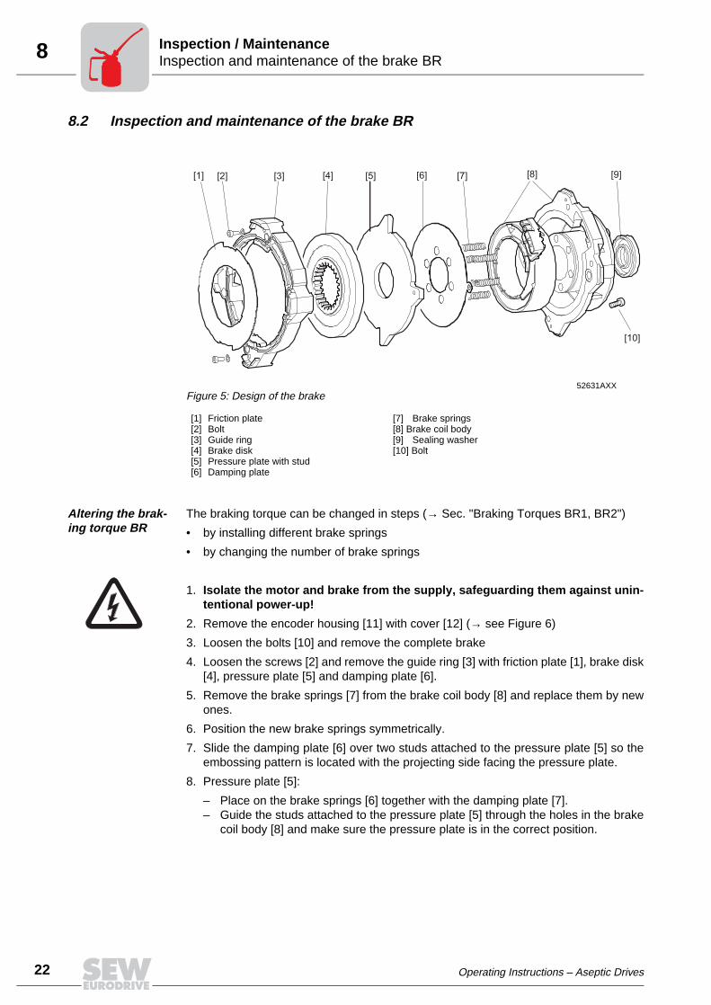
22
8 nspection and maintenance of the brake BRnspection / Maintenance
8.2 Inspection and maintenance of the brake BR
Altering the brak-ing torque BR
The braking torque can be changed in steps (→ Sec. "Braking Torques BR1, BR2")
• by installing different brake springs
• by changing the number of brake springs
1. Isolate the motor and brake from the supply, safeguarding them against unin-tentional power-up!
2. Remove the encoder housing [11] with cover [12] (→ see Figure 6)
3. Loosen the bolts [10] and remove the complete brake
4. Loosen the screws [2] and remove the guide ring [3] with friction plate [1], brake disk[4], pressure plate [5] and damping plate [6].
5. Remove the brake springs [7] from the brake coil body [8] and replace them by newones.
6. Position the new brake springs symmetrically.
7. Slide the damping plate [6] over two studs attached to the pressure plate [5] so theembossing pattern is located with the projecting side facing the pressure plate.
8. Pressure plate [5]:
– Place on the brake springs [6] together with the damping plate [7].– Guide the studs attached to the pressure plate [5] through the holes in the brake
coil body [8] and make sure the pressure plate is in the correct position.
52631AXXFigure 5: Design of the brake
[1] Friction plate[2] Bolt[3] Guide ring[4] Brake disk[5] Pressure plate with stud[6] Damping plate
[7] Brake springs[8] Brake coil body[9] Sealing washer[10] Bolt
[1] [2] [3] [4] [5] [6] [7] [8] [9]
[10]
II
Operating Instructions – Aseptic Drives
8Inspection and maintenance of the brake BRInspection / Maintenance
9. Place the flat side of the brake disk [4] on the pressure plate [8].
Note: Do not bring the disk into contact with grease or oil!
10.Place the guide ring [3] and friction disk [1] onto the brake disk [4], press down andinstall the screws [2].
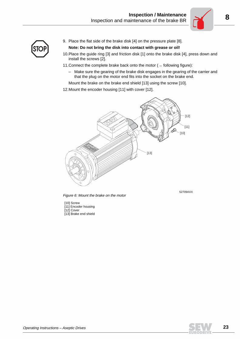
11.Connect the complete brake back onto the motor (→ following figure):
– Make sure the gearing of the brake disk engages in the gearing of the carrier andthat the plug on the motor end fits into the socket on the brake end.
Mount the brake on the brake end shield [13] using the screw [10].
12.Mount the encoder housing [11] with cover [12].
52709AXXFigure 6: Mount the brake on the motor
[10] Screw[11] Encoder housing[12] Cover[13] Brake end shield
[10]
[11]
[12]
[13]
Operating Instructions – Aseptic Drives
23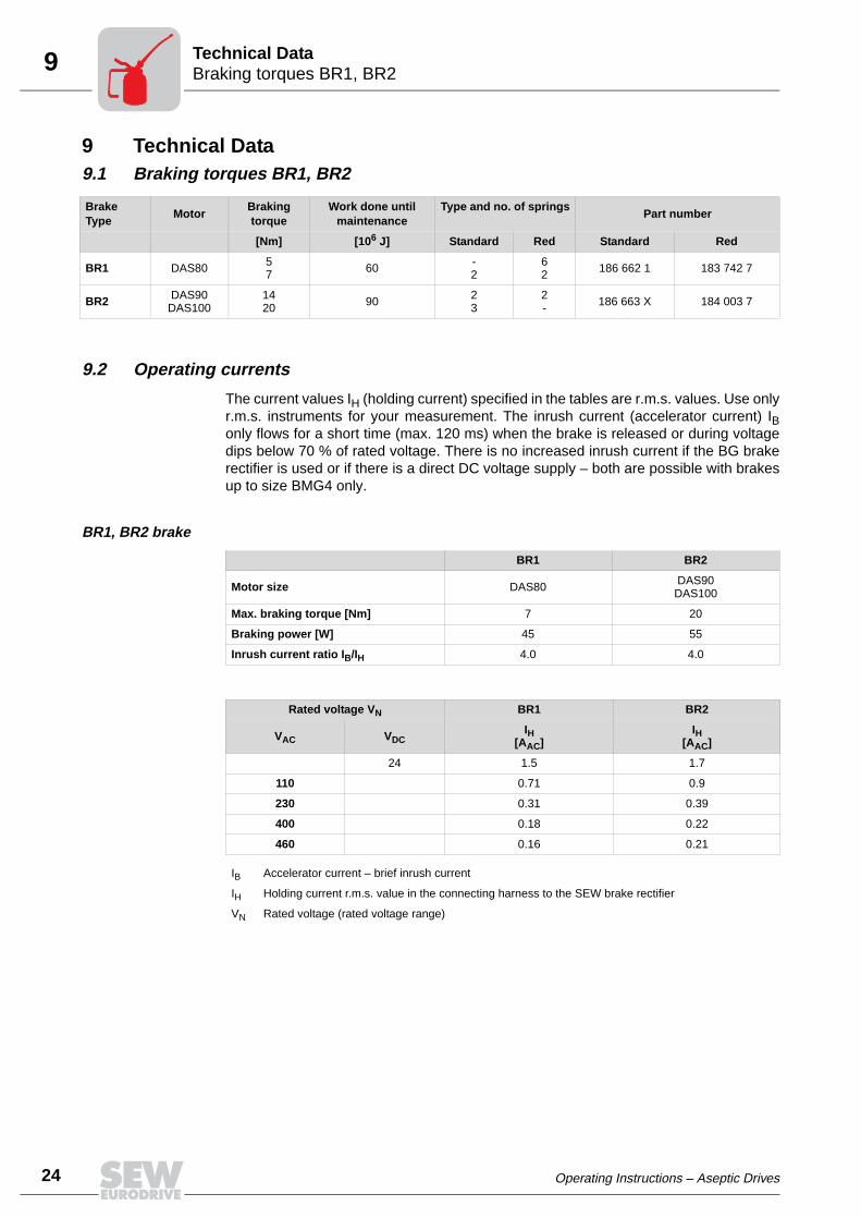
24
9 raking torques BR1, BR2echnical Data
9 Technical Data9.1 Braking torques BR1, BR2
9.2 Operating currents
The current values IH (holding current) specified in the tables are r.m.s. values. Use onlyr.m.s. instruments for your measurement. The inrush current (accelerator current) IBonly flows for a short time (max. 120 ms) when the brake is released or during voltagedips below 70 % of rated voltage. There is no increased inrush current if the BG brakerectifier is used or if there is a direct DC voltage supply – both are possible with brakesup to size BMG4 only.
BR1, BR2 brake
BrakeType
MotorBraking torque
Work done until maintenance
Type and no. of springsPart number
[Nm] [106 J] Standard Red Standard Red
BR1 DAS80 57 60 -
262 186 662 1 183 742 7
BR2 DAS90DAS100
1420 90 2
32- 186 663 X 184 003 7
BR1 BR2
Motor size DAS80 DAS90DAS100
Max. braking torque [Nm] 7 20
Braking power [W] 45 55
Inrush current ratio IB/IH 4.0 4.0
Rated voltage VN BR1 BR2
IH[AAC]
IH[AAC]VAC VDC
24 1.5 1.7
110 0.71 0.9
230 0.31 0.39
400 0.18 0.22
460 0.16 0.21
IB Accelerator current – brief inrush current
IH Holding current r.m.s. value in the connecting harness to the SEW brake rectifier
VN Rated voltage (rated voltage range)
BT
Operating Instructions – Aseptic Drives
9Gear unit gaskets/sealsTechnical Data
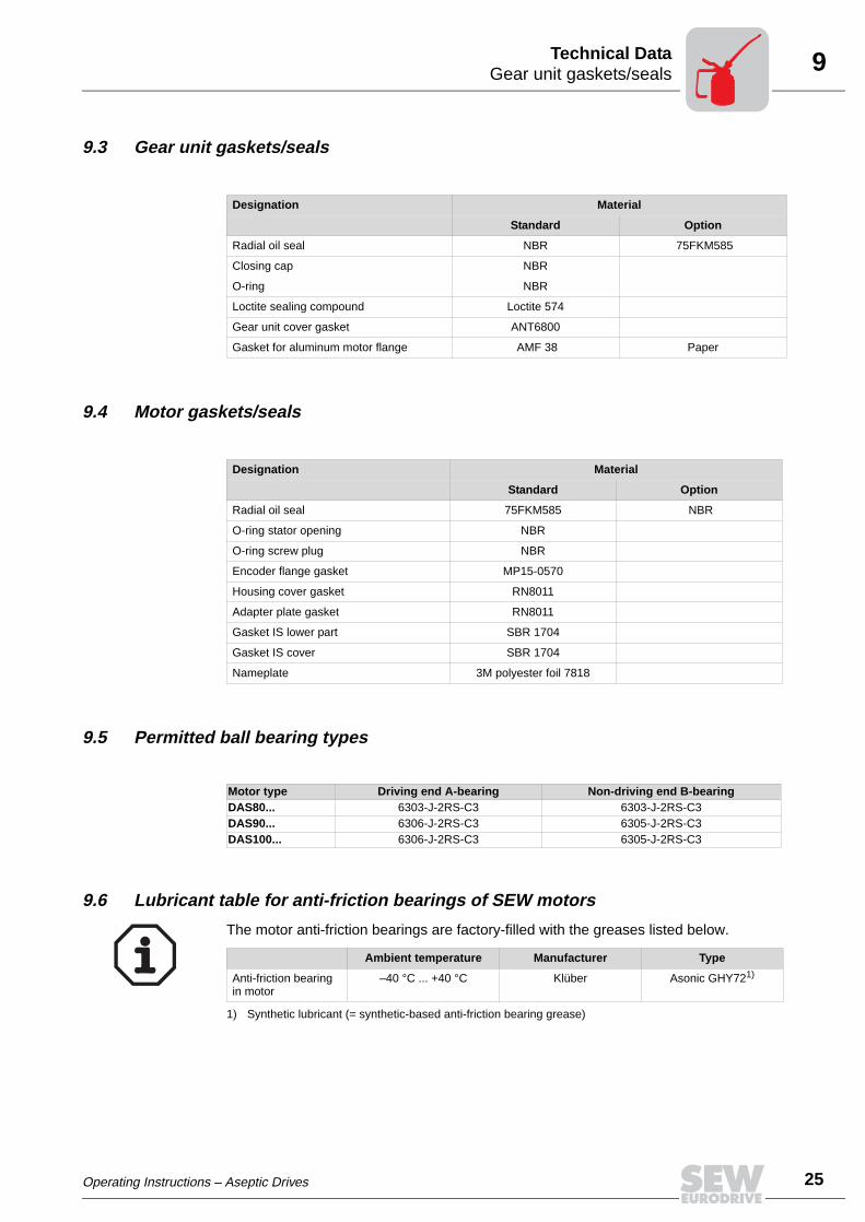
9.3 Gear unit gaskets/seals
9.4 Motor gaskets/seals
9.5 Permitted ball bearing types
9.6 Lubricant table for anti-friction bearings of SEW motors
The motor anti-friction bearings are factory-filled with the greases listed below.
Designation Material
Standard Option
Radial oil seal NBR 75FKM585
Closing cap NBR
O-ring NBR
Loctite sealing compound Loctite 574
Gear unit cover gasket ANT6800
Gasket for aluminum motor flange AMF 38 Paper
Designation Material
Standard Option
Radial oil seal 75FKM585 NBR
O-ring stator opening NBR
O-ring screw plug NBR
Encoder flange gasket MP15-0570
Housing cover gasket RN8011
Adapter plate gasket RN8011
Gasket IS lower part SBR 1704
Gasket IS cover SBR 1704
Nameplate 3M polyester foil 7818
Motor type Driving end A-bearing Non-driving end B-bearingDAS80... 6303-J-2RS-C3 6303-J-2RS-C3DAS90... 6306-J-2RS-C3 6305-J-2RS-C3DAS100... 6306-J-2RS-C3 6305-J-2RS-C3
Ambient temperature Manufacturer Type
Anti-friction bearing in motor
–40 °C ... +40 °C Klüber Asonic GHY721)
1) Synthetic lubricant (= synthetic-based anti-friction bearing grease)
Operating Instructions – Aseptic Drives
25
10
26
Index
10 Index
AAltering the braking torque BR 22
BBall bearing 25
Brake problems 20
CConnecting accessory equipment 17
Connecting the brake 17
Connecting the motor using the IS plug connector 12
EElectrical Installation 11
Extended storage of motors 9
FFrequency inverter operation 11
GGear unit seal 25
IInspection 21
Inspection and maintenance of brake BR 22
Inspection and maintenance of the brake BR03 22
Inspection intervals 21
Installation tolerances 10
Installing the plug connector 15
IS plug connector 12
LLine cross section 12
Lubricant table for anti-friction bearings of motors 25
MMaintenance 21
Maintenance intervals 21
Malfunctions 19
Mechanical Installation 9Motor Design 7Motor gasket 25
Motor problems 19
Mounting position of the upper section of the plugconnector 16
NNameplate 8
OOperating currents 24
PPermitted ball bearing types 25
SSafety Notes 5Serial number 8Startup 18
TTechnical Data 24
Transportation 6
UUnit designation 8
WWiring the upper section of the plug connector 13
Operating Instructions – Aseptic Drives
Address List
Address ListGermany
HeadquartersProductionSalesService
Bruchsal SEW-EURODRIVE GmbH & Co KGErnst-Blickle-Straße 42 D-76646 BruchsalP.O. BoxPostfach 3023 · D-76642 Bruchsal
Tel. +49 7251 75-0Fax +49 7251 75-1970http://[email protected] Electronics:Tel. +49 171 7210791Service Gear Units and Motors:Tel. +49 172 7601377
AssemblyService
Garbsen (near Hannover)
SEW-EURODRIVE GmbH & Co KGAlte Ricklinger Straße 40-42 D-30823 GarbsenP.O. BoxPostfach 110453 · D-30804 Garbsen
Tel. +49 5137 8798-30Fax +49 5137 [email protected]
Kirchheim (near München)
SEW-EURODRIVE GmbH & Co KGDomagkstraße 5D-85551 Kirchheim
Tel. +49 89 909552-10Fax +49 89 [email protected]
Langenfeld (near Düsseldorf)
SEW-EURODRIVE GmbH & Co KGSiemensstraße 1D-40764 Langenfeld
Tel. +49 2173 8507-30Fax +49 2173 [email protected]
Meerane(near Zwickau)
SEW-EURODRIVE GmbH & Co KGDänkritzer Weg 1D-08393 Meerane
Tel. +49 3764 7606-0Fax +49 3764 [email protected]
Additional addresses for service in Germany provided on request!
France
ProductionSalesService
Haguenau SEW-USOCOME 48-54, route de Soufflenheim B. P. 185F-67506 Haguenau Cedex
Tel. +33 3 88 73 67 00 Fax +33 3 88 73 66 00http://[email protected]
AssemblySalesService
Bordeaux SEW-USOCOME Parc d’activités de Magellan62, avenue de Magellan - B. P. 182F-33607 Pessac Cedex
Tel. +33 5 57 26 39 00Fax +33 5 57 26 39 09
Lyon SEW-USOCOME Parc d’Affaires RooseveltRue Jacques TatiF-69120 Vaulx en Velin
Tel. +33 4 72 15 37 00Fax +33 4 72 15 37 15
Paris SEW-USOCOME Zone industrielle 2, rue Denis Papin F-77390 Verneuil I’Etang
Tel. +33 1 64 42 40 80Fax +33 1 64 42 40 88
Additional addresses for service in France provided on request!
Algeria
Sales Alger Réducom 16, rue des Frères ZaghnounBellevue El-Harrach16200 Alger
Tel. +213 21 8222-84Fax +213 21 8222-84
Argentina
AssemblySalesService
Buenos Aires SEW EURODRIVE ARGENTINA S.A.Centro Industrial Garin, Lote 35Ruta Panamericana Km 37,51619 Garin
Tel. +54 3327 4572-84Fax +54 3327 [email protected]
Australia
AssemblySalesService
Melbourne SEW-EURODRIVE PTY. LTD.27 Beverage DriveTullamarine, Victoria 3043
Tel. +61 3 9933-1000Fax +61 3 9933-1003http://[email protected]
Sydney SEW-EURODRIVE PTY. LTD.9, Sleigh Place, Wetherill Park New South Wales, 2164
Tel. +61 2 9725-9900Fax +61 2 [email protected]
12/2003 27
Address List
28
Austria
AssemblySalesService
Wien SEW-EURODRIVE Ges.m.b.H. Richard-Strauss-Strasse 24A-1230 Wien
Tel. +43 1 617 55 00-0Fax +43 1 617 55 00-30http://[email protected]
Belgium
AssemblySalesService
Brüssel CARON-VECTOR S.A.Avenue Eiffel 5B-1300 Wavre
Tel. +32 10 231-311Fax +32 10 231-336http://[email protected]
Brazil
ProductionSalesService
Sao Paulo SEW-EURODRIVE Brasil Ltda.Avenida Amâncio Gaiolli, 50Caixa Postal: 201-07111-970Guarulhos/SP - Cep.: 07251-250
Tel. +55 11 6489-9133Fax +55 11 6480-3328http://[email protected]
Additional addresses for service in Brazil provided on request!
Bulgaria
Sales Sofia BEVER-DRIVE GMBHBogdanovetz Str.1BG-1606 Sofia
Tel. +359 2 9532565Fax +359 2 [email protected]
Cameroon
Sales Douala Electro-ServicesRue Drouot AkwaB.P. 2024Douala
Tel. +237 4322-99Fax +237 4277-03
Canada
AssemblySalesService
Toronto SEW-EURODRIVE CO. OF CANADA LTD. 210 Walker Drive Bramalea, Ontario L6T3W1
Tel. +1 905 791-1553Fax +1 905 791-2999http://[email protected]
Vancouver SEW-EURODRIVE CO. OF CANADA LTD.7188 Honeyman Street Delta. B.C. V4G 1 E2
Tel. +1 604 946-5535Fax +1 604 [email protected]
Montreal SEW-EURODRIVE CO. OF CANADA LTD.2555 Rue Leger Street LaSalle, Quebec H8N 2V9
Tel. +1 514 367-1124Fax +1 514 [email protected]
Additional addresses for service in Canada provided on request!
Chile
AssemblySalesService
Santiago de Chile
SEW-EURODRIVE CHILE LTDA.Las Encinas 1295Parque Industrial Valle GrandeLAMPARCH-Santiago de ChileP.O. BoxCasilla 23 Correo Quilicura - Santiago - Chile
Tel. +56 2 75770-00Fax +56 2 [email protected]
China
ProductionAssemblySalesService
Tianjin SEW-EURODRIVE (Tianjin) Co., Ltd.No. 46, 7th Avenue, TEDA Tianjin 300457
Tel. +86 22 25322612Fax +86 22 25322611http://www.sew.com.cn
AssemblySalesService
Suzhou SEW-EURODRIVE (Suzhou) Co., Ltd.333, Suhong Middle RoadSuzhou Industrial ParkJiangsu Province, 215021P. R. China
Tel. +86 512 62581781Fax +86 512 [email protected]
12/2003
Address List
Colombia
AssemblySalesService
Bogotá SEW-EURODRIVE COLOMBIA LTDA. Calle 22 No. 132-60Bodega 6, Manzana BSantafé de Bogotá
Tel. +57 1 54750-50Fax +57 1 [email protected]
Croatia
SalesService
Zagreb KOMPEKS d. o. o.PIT Erdödy 4 IIHR 10 000 Zagreb
Tel. +385 1 4613-158Fax +385 1 [email protected]
Czech Republic
Sales Praha SEW-EURODRIVE CZ S.R.O.Business Centrum Praha Luná 591CZ-16000 Praha 6 - Vokovice
Tel. +420 220121234 + 220121236Fax +420 220121237http://[email protected]
Denmark
AssemblySalesService
Kopenhagen SEW-EURODRIVEA/SGeminivej 28-30, P.O. Box 100DK-2670 Greve
Tel. +45 43 9585-00Fax +45 43 9585-09http://[email protected]
Estonia
Sales Tallin ALAS-KUUL ASPaldiski mnt.125EE 0006 Tallin
Tel. +372 6593230Fax +372 6593231
Finland
AssemblySalesService
Lahti SEW-EURODRIVE OYVesimäentie 4FIN-15860 Hollola 2
Tel. +358 3 589-300Fax +358 3 7806-211http://[email protected]
Gabon
Sales Libreville Electro-ServicesB.P. 1889Libreville
Tel. +241 7340-11Fax +241 7340-12
Great Britain
AssemblySalesService
Normanton SEW-EURODRIVE Ltd.Beckbridge Industrial Estate P.O. Box No.1GB-Normanton, West- Yorkshire WF6 1QR
Tel. +44 1924 893-855Fax +44 1924 893-702http://[email protected]
Greece
SalesService
Athen Christ. Boznos & Son S.A.12, Mavromichali StreetP.O. Box 80136, GR-18545 Piraeus
Tel. +30 2 1042 251-34 Fax +30 2 1042 251-59http://[email protected]
Hong Kong
AssemblySalesService
Hong Kong SEW-EURODRIVE LTD.Unit No. 801-806, 8th FloorHong Leong Industrial ComplexNo. 4, Wang Kwong Road Kowloon, Hong Kong
Tel. +852 2 7960477 + 79604654Fax +852 2 [email protected]
Hungary
SalesService
Budapest SEW-EURODRIVE Kft.H-1037 BudapestKunigunda u. 18
Tel. +36 1 437 06-58Fax +36 1 437 [email protected]
12/2003 29
Address List
30
India
AssemblySalesService
Baroda SEW-EURODRIVE India Pvt. Ltd.Plot No. 4, GidcPor Ramangamdi · Baroda - 391 243Gujarat
Tel. +91 265 2831021Fax +91 265 [email protected]
Technical Offices Bangalore SEW-EURODRIVE India Private Limited308, Prestige Centre Point7, Edward RoadBangalore
Tel. +91 80 22266565Fax +91 80 [email protected]
Mumbai SEW-EURODRIVE India Private Limited312 A, 3rd Floor, Acme PlazaAndheri Kurla Road, Andheri (E)Mumbai
Tel. +91 22 28348440Fax +91 22 [email protected]
Ireland
SalesService
Dublin Alperton Engineering Ltd. 48 Moyle RoadDublin Industrial EstateGlasnevin, Dublin 11
Tel. +353 1 830-6277Fax +353 1 830-6458
Italy
AssemblySalesService
Milano SEW-EURODRIVE di R. Blickle & Co.s.a.s.Via Bernini,14 I-20020 Solaro (Milano)
Tel. +39 2 96 9801Fax +39 2 96 [email protected]
Ivory Coast
Sales Abidjan SICASte industrielle et commerciale pour l’Afrique165, Bld de MarseilleB.P. 2323, Abidjan 08
Tel. +225 2579-44Fax +225 2584-36
Japan
AssemblySalesService
Toyoda-cho SEW-EURODRIVE JAPAN CO., LTD 250-1, Shimoman-no,Toyoda-cho, Iwata gunShizuoka prefecture, 438-0818
Tel. +81 538 373811Fax +81 538 [email protected]
Korea
AssemblySalesService
Ansan-City SEW-EURODRIVE KOREA CO., LTD. B 601-4, Banweol Industrial Estate Unit 1048-4, Shingil-DongAnsan 425-120
Tel. +82 31 492-8051Fax +82 31 [email protected]
Latvia
Sales Riga SIA Gultni21, Unijas StreetLV-1039 Riga
Tel. +371 7 840202Fax +371 7 [email protected]
Lebanon
Sales Beirut Gabriel Acar & Fils sarlB. P. 80484Bourj Hammoud, Beirut
Tel. +961 1 4947-86 +961 1 4982-72+961 3 2745-39Fax +961 1 4949-71 [email protected]
Lithuania
Sales Alytus UAB IrsevaMerkines g. 2ALT-4580 Alytus
Tel. +370 315 79204Fax +370 315 [email protected]
Luxembourg
AssemblySalesService
Brüssel CARON-VECTOR S.A.Avenue Eiffel 5B-1300 Wavre
Tel. +32 10 231-311Fax +32 10 231-336http://[email protected]
12/2003
Address List
Malaysia
AssemblySalesService
Johore SEW-EURODRIVE SDN BHD No. 95, Jalan Seroja 39, Taman Johor Jaya81000 Johor Bahru, JohorWest Malaysia
Tel. +60 7 3549409Fax +60 7 [email protected]
Morocco
Sales Casablanca S. R. M.Société de Réalisations Mécaniques 5, rue Emir Abdelkader05 Casablanca
Tel. +212 2 6186-69 + 6186-70 + 6186-71Fax +212 2 [email protected]
Netherlands
AssemblySalesService
Rotterdam VECTOR Aandrijftechniek B.V. Industrieweg 175 NL-3044 AS RotterdamPostbus 10085NL-3004 AB Rotterdam
Tel. +31 10 4463-700Fax +31 10 4155-552http://[email protected]
New Zealand
AssemblySalesService
Auckland SEW-EURODRIVE NEW ZEALAND LTD. P.O. Box 58-428 82 Greenmount driveEast Tamaki Auckland
Tel. +64 9 2745627Fax +64 9 [email protected]
Christchurch SEW-EURODRIVE NEW ZEALAND LTD. 10 Settlers Crescent, FerrymeadChristchurch
Tel. +64 3 384-6251Fax +64 3 [email protected]
Norway
AssemblySalesService
Moss SEW-EURODRIVE A/SSolgaard skog 71N-1599 Moss
Tel. +47 69 241-020Fax +47 69 [email protected]
Peru
AssemblySalesService
Lima SEW DEL PERU MOTORES REDUCTORES S.A.C.Los Calderos <FmSdata>[Idot ] 120-124Urbanizacion Industrial Vulcano, ATE, Lima
Tel. +51 1 3495280Fax +51 1 [email protected]
Poland
AssemblySalesService
Lodz SEW-EURODRIVE Polska Sp.z.o.o.ul. Techniczna 5 PL-92-518 Lodz
Tel. +48 42 67710-90Fax +48 42 67710-99http://[email protected]
Portugal
AssemblySalesService
Coimbra SEW-EURODRIVE, LDA. Apartado 15 P-3050-901 Mealhada
Tel. +351 231 20 9670Fax +351 231 20 3685http://[email protected]
Romania
SalesService
Bucuresti Sialco Trading SRL str. Madrid nr.4 71222 Bucuresti
Tel. +40 21 230-1328Fax +40 21 230-7170 [email protected]
Russia
Sales St. Petersburg ZAO SEW-EURODRIVE P.O. Box 263 RUS-195220 St. Petersburg
Tel. +7 812 5357142 +812 5350430Fax +7 812 [email protected]
Senegal
Sales Dakar SENEMECA Mécanique GénéraleKm 8, Route de Rufisque B.P. 3251, Dakar
Tel. +221 849 47-70Fax +221 849 [email protected]
12/2003
31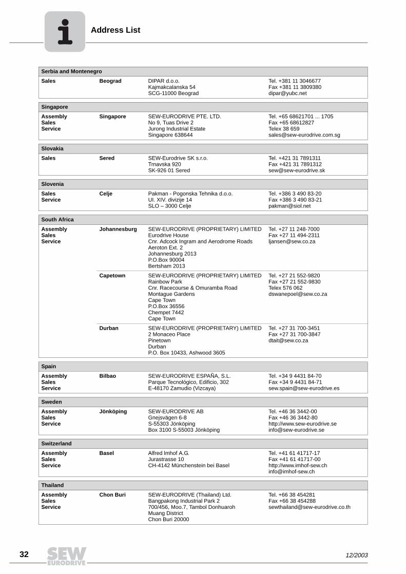
ddress List
32
Serbia and Montenegro
Sales Beograd DIPAR d.o.o.Kajmakcalanska 54SCG-11000 Beograd
Tel. +381 11 3046677Fax +381 11 [email protected]
Singapore
AssemblySalesService
Singapore SEW-EURODRIVE PTE. LTD. No 9, Tuas Drive 2 Jurong Industrial Estate Singapore 638644
Tel. +65 68621701 ... 1705Fax +65 68612827Telex 38 659 [email protected]
Slovakia
Sales Sered SEW-Eurodrive SK s.r.o.Trnavska 920SK-926 01 Sered
Tel. +421 31 7891311Fax +421 31 [email protected]
Slovenia
SalesService
Celje Pakman - Pogonska Tehnika d.o.o.UI. XIV. divizije 14SLO – 3000 Celje
Tel. +386 3 490 83-20Fax +386 3 490 [email protected]
South Africa
AssemblySalesService
Johannesburg SEW-EURODRIVE (PROPRIETARY) LIMITEDEurodrive House Cnr. Adcock Ingram and Aerodrome RoadsAeroton Ext. 2Johannesburg 2013P.O.Box 90004Bertsham 2013
Tel. +27 11 248-7000Fax +27 11 [email protected]
Capetown SEW-EURODRIVE (PROPRIETARY) LIMITED Rainbow ParkCnr. Racecourse & Omuramba RoadMontague GardensCape TownP.O.Box 36556Chempet 7442 Cape Town
Tel. +27 21 552-9820Fax +27 21 552-9830Telex 576 [email protected]
Durban SEW-EURODRIVE (PROPRIETARY) LIMITED2 Monaceo PlacePinetownDurbanP.O. Box 10433, Ashwood 3605
Tel. +27 31 700-3451Fax +27 31 [email protected]
Spain
AssemblySalesService
Bilbao SEW-EURODRIVE ESPAÑA, S.L. Parque Tecnológico, Edificio, 302E-48170 Zamudio (Vizcaya)
Tel. +34 9 4431 84-70Fax +34 9 4431 [email protected]
Sweden
AssemblySalesService
Jönköping SEW-EURODRIVE ABGnejsvägen 6-8S-55303 JönköpingBox 3100 S-55003 Jönköping
Tel. +46 36 3442-00Fax +46 36 3442-80http://[email protected]
Switzerland
AssemblySalesService
Basel Alfred lmhof A.G.Jurastrasse 10 CH-4142 Münchenstein bei Basel
Tel. +41 61 41717-17Fax +41 61 41717-00http://[email protected]
Thailand
AssemblySalesService
Chon Buri SEW-EURODRIVE (Thailand) Ltd.Bangpakong Industrial Park 2700/456, Moo.7, Tambol DonhuarohMuang DistrictChon Buri 20000
Tel. +66 38 454281Fax +66 38 [email protected]
A
12/2003
Address List
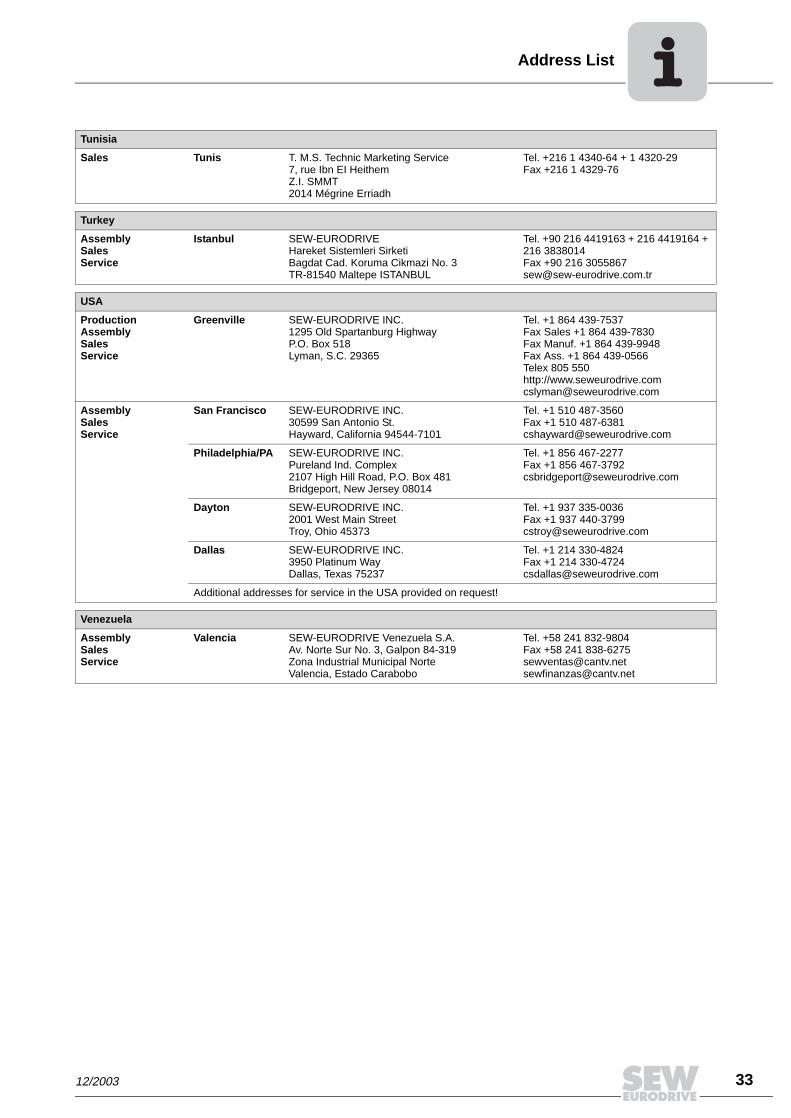
Tunisia
Sales Tunis T. M.S. Technic Marketing Service7, rue Ibn EI Heithem Z.I. SMMT2014 Mégrine Erriadh
Tel. +216 1 4340-64 + 1 4320-29Fax +216 1 4329-76
Turkey
AssemblySalesService
Istanbul SEW-EURODRIVE Hareket Sistemleri Sirketi Bagdat Cad. Koruma Cikmazi No. 3 TR-81540 Maltepe ISTANBUL
Tel. +90 216 4419163 + 216 4419164 + 216 3838014Fax +90 216 [email protected]
USA
ProductionAssemblySalesService
Greenville SEW-EURODRIVE INC. 1295 Old Spartanburg Highway P.O. Box 518Lyman, S.C. 29365
Tel. +1 864 439-7537Fax Sales +1 864 439-7830Fax Manuf. +1 864 439-9948Fax Ass. +1 864 439-0566Telex 805 550 http://[email protected]
AssemblySalesService
San Francisco SEW-EURODRIVE INC. 30599 San Antonio St.Hayward, California 94544-7101
Tel. +1 510 487-3560Fax +1 510 [email protected]
Philadelphia/PA SEW-EURODRIVE INC. Pureland Ind. Complex 2107 High Hill Road, P.O. Box 481Bridgeport, New Jersey 08014
Tel. +1 856 467-2277Fax +1 856 [email protected]
Dayton SEW-EURODRIVE INC.2001 West Main Street Troy, Ohio 45373
Tel. +1 937 335-0036Fax +1 937 [email protected]
Dallas SEW-EURODRIVE INC.3950 Platinum Way Dallas, Texas 75237
Tel. +1 214 330-4824Fax +1 214 [email protected]
Additional addresses for service in the USA provided on request!
Venezuela
AssemblySalesService
Valencia SEW-EURODRIVE Venezuela S.A.Av. Norte Sur No. 3, Galpon 84-319Zona Industrial Municipal NorteValencia, Estado Carabobo
Tel. +58 241 832-9804Fax +58 241 [email protected]@cantv.net
12/2003
33

www.sew-eurodrive.com
SEW-EURODRIVE GmbH & Co KGErnst-Blickle-Str. 42 · 76646 Bruchsal / GermanyTel. +49 7251 75-0 · Fax +49 7251 [email protected]