Embed Size (px)
Citation preview

IEC 61000-2-2 Edition 2.0 2017-06
INTERNATIONAL STANDARD NORME INTERNATIONALE
IEC
610
00-2
-2:2
002-
03/A
MD
1:20
17-0
6(en
-fr)
®
BASIC EMC PUBLICATION PUBLICATION FONDAMENTALE EN CEM AMENDMENT 1 AMENDEMENT 1 Electromagnetic compatibility (EMC) – Part 2-2: Environment – Compatibility levels for low-frequency conducted disturbances and signalling in public low-voltage power supply systems Compatibilité électromagnétique (CEM) – Partie 2-2: Environnement – Niveaux de compatibilité pour les perturbations conduites à basse fréquence et la transmission des signaux sur les réseaux publics d’alimentation basse tension
iTeh STANDARD PREVIEW(standards.iteh.ai)
IEC 61000-2-2:2002/AMD1:2017https://standards.iteh.ai/catalog/standards/sist/4b6f7a2c-b217-4680-8256-
d1343123a579/iec-61000-2-2-2002-amd1-2017
THIS PUBLICATION IS COPYRIGHT PROTECTED Copyright © 2017 IEC, Geneva, Switzerland All rights reserved. Unless otherwise specified, no part of this publication may be reproduced or utilized in any form or by any means, electronic or mechanical, including photocopying and microfilm, without permission in writing from either IEC or IEC's member National Committee in the country of the requester. If you have any questions about IEC copyright or have an enquiry about obtaining additional rights to this publication, please contact the address below or your local IEC member National Committee for further information. Droits de reproduction réservés. Sauf indication contraire, aucune partie de cette publication ne peut être reproduite ni utilisée sous quelque forme que ce soit et par aucun procédé, électronique ou mécanique, y compris la photocopie et les microfilms, sans l'accord écrit de l'IEC ou du Comité national de l'IEC du pays du demandeur. Si vous avez des questions sur le copyright de l'IEC ou si vous désirez obtenir des droits supplémentaires sur cette publication, utilisez les coordonnées ci-après ou contactez le Comité national de l'IEC de votre pays de résidence.
IEC Central Office Tel.: +41 22 919 02 11 3, rue de Varembé Fax: +41 22 919 03 00 CH-1211 Geneva 20 [email protected] Switzerland www.iec.ch
About the IEC The International Electrotechnical Commission (IEC) is the leading global organization that prepares and publishes International Standards for all electrical, electronic and related technologies. About IEC publications The technical content of IEC publications is kept under constant review by the IEC. Please make sure that you have the latest edition, a corrigenda or an amendment might have been published. IEC Catalogue - webstore.iec.ch/catalogue The stand-alone application for consulting the entire bibliographical information on IEC International Standards, Technical Specifications, Technical Reports and other documents. Available for PC, Mac OS, Android Tablets and iPad. IEC publications search - www.iec.ch/searchpub The advanced search enables to find IEC publications by a variety of criteria (reference number, text, technical committee,…). It also gives information on projects, replaced and withdrawn publications. IEC Just Published - webstore.iec.ch/justpublished Stay up to date on all new IEC publications. Just Published details all new publications released. Available online and also once a month by email.
Electropedia - www.electropedia.org The world's leading online dictionary of electronic and electrical terms containing 20 000 terms and definitions in English and French, with equivalent terms in 16 additional languages. Also known as the International Electrotechnical Vocabulary (IEV) online. IEC Glossary - std.iec.ch/glossary 65 000 electrotechnical terminology entries in English and French extracted from the Terms and Definitions clause of IEC publications issued since 2002. Some entries have been collected from earlier publications of IEC TC 37, 77, 86 and CISPR. IEC Customer Service Centre - webstore.iec.ch/csc If you wish to give us your feedback on this publication or need further assistance, please contact the Customer Service Centre: [email protected].
A propos de l'IEC La Commission Electrotechnique Internationale (IEC) est la première organisation mondiale qui élabore et publie des Normes internationales pour tout ce qui a trait à l'électricité, à l'électronique et aux technologies apparentées. A propos des publications IEC Le contenu technique des publications IEC est constamment revu. Veuillez vous assurer que vous possédez l’édition la plus récente, un corrigendum ou amendement peut avoir été publié. Catalogue IEC - webstore.iec.ch/catalogue Application autonome pour consulter tous les renseignements bibliographiques sur les Normes internationales, Spécifications techniques, Rapports techniques et autres documents de l'IEC. Disponible pour PC, Mac OS, tablettes Android et iPad. Recherche de publications IEC - www.iec.ch/searchpub La recherche avancée permet de trouver des publications IEC en utilisant différents critères (numéro de référence, texte, comité d’études,…). Elle donne aussi des informations sur les projets et les publications remplacées ou retirées. IEC Just Published - webstore.iec.ch/justpublished Restez informé sur les nouvelles publications IEC. Just Published détaille les nouvelles publications parues. Disponible en ligne et aussi une fois par mois par email.
Electropedia - www.electropedia.org Le premier dictionnaire en ligne de termes électroniques et électriques. Il contient 20 000 termes et définitions en anglais et en français, ainsi que les termes équivalents dans 16 langues additionnelles. Egalement appelé Vocabulaire Electrotechnique International (IEV) en ligne. Glossaire IEC - std.iec.ch/glossary 65 000 entrées terminologiques électrotechniques, en anglais et en français, extraites des articles Termes et Définitions des publications IEC parues depuis 2002. Plus certaines entrées antérieures extraites des publications des CE 37, 77, 86 et CISPR de l'IEC. Service Clients - webstore.iec.ch/csc Si vous désirez nous donner des commentaires sur cette publication ou si vous avez des questions contactez-nous: [email protected].
iTeh STANDARD PREVIEW(standards.iteh.ai)
IEC 61000-2-2:2002/AMD1:2017https://standards.iteh.ai/catalog/standards/sist/4b6f7a2c-b217-4680-8256-
d1343123a579/iec-61000-2-2-2002-amd1-2017
IEC 61000-2-2 Edition 2.0 2017-06
INTERNATIONAL STANDARD NORME INTERNATIONALE
INTERNATIONAL ELECTROTECHNICAL COMMISSION
COMMISSION ELECTROTECHNIQUE INTERNATIONALE ICS 33.100.01
ISBN 978-2-8322-4431-9
® Registered trademark of the International Electrotechnical Commission Marque déposée de la Commission Electrotechnique Internationale
®
Warning! Make sure that you obtained this publication from an authorized distributor. Attention! Veuillez vous assurer que vous avez obtenu cette publication via un distributeur agréé.
BASIC EMC PUBLICATION PUBLICATION FONDAMENTALE EN CEM
Electromagnetic compatibility (EMC) – Part 2-2: Environment – Compatibility levels for low-frequency conducted disturbances and signalling in public low-voltage power supply systems Compatibilité électromagnétique (CEM) – Partie 2-2: Environnement – Niveaux de compatibilité pour les perturbations conduites à basse fréquence et la transmission des signaux sur les réseaux publics d’alimentation basse tension
AMENDMENT 1 AMENDEMENT 1
iTeh STANDARD PREVIEW(standards.iteh.ai)
IEC 61000-2-2:2002/AMD1:2017https://standards.iteh.ai/catalog/standards/sist/4b6f7a2c-b217-4680-8256-
d1343123a579/iec-61000-2-2-2002-amd1-2017
– 2 – IEC 61000-2-2:2002/AMD1:2017 © IEC 2017
FOREWORD
This amendment has been prepared by subcommittee 77A: EMC – Low frequency phenomena, of IEC technical committee 77: Electromagnetic compatibility.
The text of this amendment is based on the following documents:
FDIS Report on voting
77A/958/FDIS 77A/962/RVD
Full information on the voting for the approval of this amendment can be found in the report on voting indicated in the above table.
The committee has decided that the contents of this amendment and the base publication will remain unchanged until the stability date indicated on the IEC website under "http://webstore.iec.ch" in the data related to the specific publication. At this date, the publication will be
• reconfirmed,
• withdrawn,
• replaced by a revised edition, or
• amended.
_____________
Introduction to Amendment 1
This amendment is related to compatibility levels in the frequency range from 2 kHz to 150 kHz. It contains:
– compatibility levels for signals from mains communicating systems up to 150 kHz; – compatibility levels for non-intentional emissions between 2 kHz and 30 kHz.
A second amendment is expected soon, containing:
– compatibility levels for non-intentional emissions between 30 kHz and 150 kHz.
1 Scope and object
Replace the existing text with the following new text:
This part of IEC 61000 is concerned with conducted electromagnetic phenomena (disturbances and signals from mains communicating systems) in the frequency range from 0 kHz to 150 kHz. It gives compatibility levels for public low voltage a.c. distribution systems having a nominal voltage up to 420 V, single-phase, or 690 V, three-phase, and a nominal frequency of 50 Hz or 60 Hz.
The compatibility levels specified in this document apply at the point of common coupling. At the power input terminals of equipment receiving its supply from the above systems, the levels of the conducted electromagnetic disturbances can, for the most part, be taken to be the same as the levels at the point of common coupling. In some situations this is not so, particularly in the case of a long line dedicated to the supply of a particular installation, or in
iTeh STANDARD PREVIEW(standards.iteh.ai)
IEC 61000-2-2:2002/AMD1:2017https://standards.iteh.ai/catalog/standards/sist/4b6f7a2c-b217-4680-8256-
d1343123a579/iec-61000-2-2-2002-amd1-2017
IEC 61000-2-2:2002/AMD1:2017 – 3 – © IEC 2017 the case of an electromagnetic phenomenon generated or amplified within the installation of which the equipment forms a part.
Compatibility levels are specified for conducted electromagnetic phenomena of the types which can be expected in public low voltage power supply systems, for guidance in the definition of:
– the limits to be set for conducted emissions into public power supply systems (including the planning levels defined in 3.1.5),
– the immunity limits to be set by product committees and others for the equipment exposed to the conducted electromagnetic phenomena present in public power supply systems.
NOTE More information on compatibility levels and other main basic EMC concepts is given in IEC TR 61000-1-1.
The electromagnetic phenomena considered are:
– voltage fluctuations and flicker; – harmonics up to and including order 40; – interharmonics up to the 40th harmonic; – voltage distortion in differential mode at higher frequencies (above the 40th harmonic up to
150 kHz); – voltage dips and short supply interruptions; – voltage unbalance; – transient overvoltages; – power frequency variation; – d.c. components; – signals from mains communicating systems (MCS).
Most of these phenomena are described in IEC TR 61000-2-1. In cases where it is not yet possible to establish compatibility levels, some information is provided in Annex B.
2 Normative references
Add the following new references:
IEC 61000-3-8, Electromagnetic compatibility (EMC) – Part 3: Limits – Section 8: Signalling on low-voltage electrical installations – Emission levels, frequency bands and electromagnetic disturbance levels
CISPR 16-1-1, Specification for radio disturbance and immunity measuring apparatus and methods – Part 1-1: Radio disturbance and immunity measuring apparatus – Measuring apparatus
CISPR 16-2-1, Specification for radio disturbance and immunity measuring apparatus and methods – Part 2-1: Methods of measurement of disturbances and immunity – Conducted disturbance measurements
3.1 General definitions
Add the following new definitions:
3.1.7 non-intentional emission conducted emission which is not intended for communication purposes
iTeh STANDARD PREVIEW(standards.iteh.ai)
IEC 61000-2-2:2002/AMD1:2017https://standards.iteh.ai/catalog/standards/sist/4b6f7a2c-b217-4680-8256-
d1343123a579/iec-61000-2-2-2002-amd1-2017
– 4 – IEC 61000-2-2:2002/AMD1:2017 © IEC 2017
Note 1 to entry: For the purposes of this document, non-intentional emissions only refer to conducted phenomena.
3.1.8 mains communicating system MCS electrical system using mains power lines to transmit information signals, either on the public electricity distribution network or within installations of network users
3.1.9 differential mode voltage voltage in differential mode voltage between any two phase conductors or between any phase conductor and the neutral conductor
Note 1 to entry: The voltage distortion in differential mode is the distortion of the voltage in differential mode.
3.1.10 unsymmetrical voltage voltage between any mains conductor (phase or neutral) and the earth
3.2 Phenomena related definitions
3.2.7 total harmonic distortion (THD) Replace, in the explanation below the equation, value H, "…is generally equal to 50, but…" with "…is generally equal to 40, but…".
4.3 Harmonics
In Table 1, replace:
17 ≤ h ≤ 49 with 17 ≤ h ≤ 37,
21 < h ≤ 45 with 21 < h ≤ 39,
10 ≤ h ≤ 50 with 10 ≤ h ≤ 40.
Add, after the existing subclause 4.4 the following new subclauses:
4.11 Voltage distortion in differential mode above the 40th harmonic up to 9 kHz
In this document, voltage distortion above the 40th harmonic up to 9 kHz is considered in relation to long-term effects, i.e. for a duration of 10 min or longer.
In the case of voltage distortion at frequencies above the 40th harmonic, it is generally not relevant whether they are at harmonic or interharmonic frequencies. They can occur both at discrete frequencies and in relatively broad bands of frequencies.
The compatibility levels for voltage distortion in differential mode above the 40th harmonic (exclusive) up to 9 kHz are given in Table 2. These compatibility levels are related to voltage distortion levels between any two phase conductors or between any phase conductor and the neutral conductor, in a bandwidth of 200 Hz, defined as follows:
∑−=
⋅+×=f
fnF fnFU
Uu
∆
∆∆
/
)/(, )(
100
1001
2
1b
100
iTeh STANDARD PREVIEW(standards.iteh.ai)
IEC 61000-2-2:2002/AMD1:2017https://standards.iteh.ai/catalog/standards/sist/4b6f7a2c-b217-4680-8256-
d1343123a579/iec-61000-2-2-2002-amd1-2017
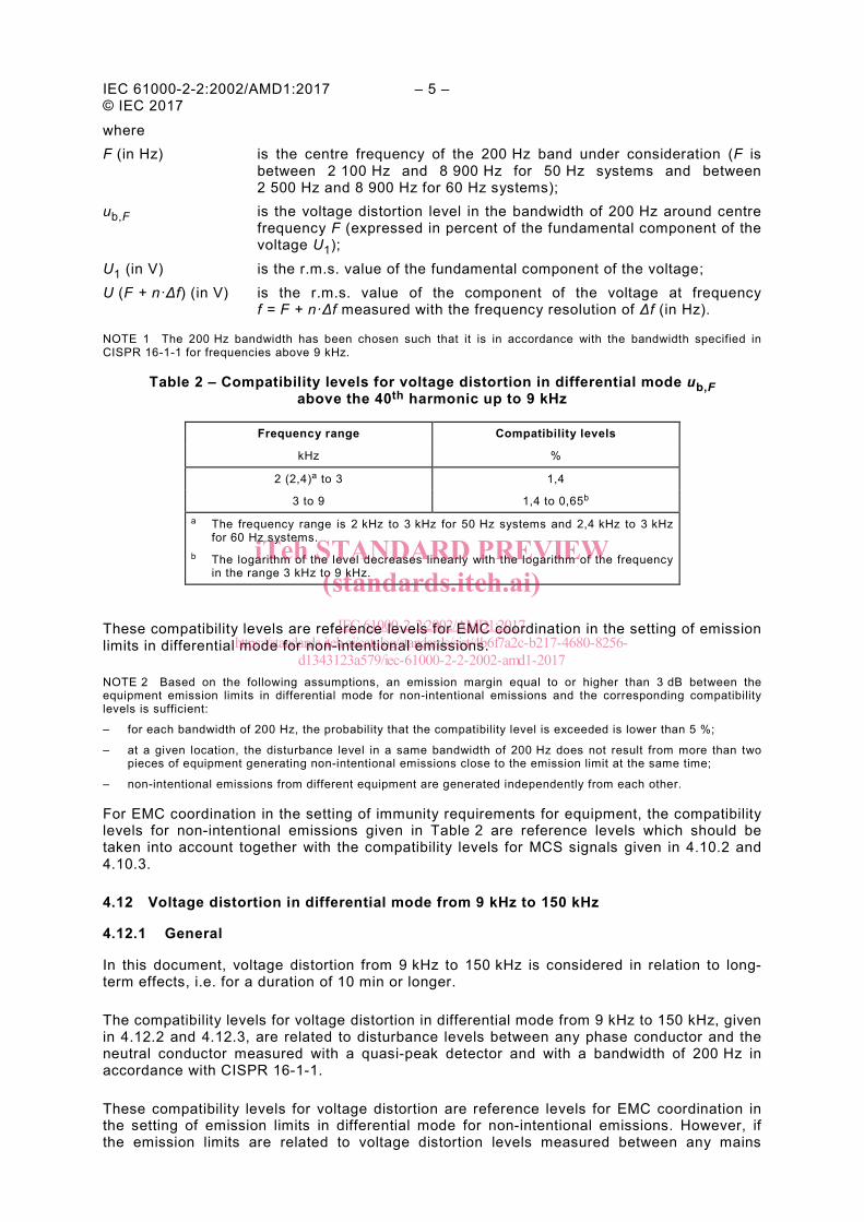
IEC 61000-2-2:2002/AMD1:2017 – 5 – © IEC 2017 where F (in Hz) is the centre frequency of the 200 Hz band under consideration (F is
between 2 100 Hz and 8 900 Hz for 50 Hz systems and between 2 500 Hz and 8 900 Hz for 60 Hz systems);
ub,F is the voltage distortion level in the bandwidth of 200 Hz around centre frequency F (expressed in percent of the fundamental component of the voltage U1);
U1 (in V) is the r.m.s. value of the fundamental component of the voltage; U (F + n·Δf) (in V) is the r.m.s. value of the component of the voltage at frequency
f = F + n·Δf measured with the frequency resolution of Δf (in Hz).
NOTE 1 The 200 Hz bandwidth has been chosen such that it is in accordance with the bandwidth specified in CISPR 16-1-1 for frequencies above 9 kHz.
Table 2 – Compatibility levels for voltage distortion in differential mode ub,F above the 40th harmonic up to 9 kHz
Frequency range Compatibility levels
kHz %
2 (2,4)a to 3 1,4
3 to 9 1,4 to 0,65b a The frequency range is 2 kHz to 3 kHz for 50 Hz systems and 2,4 kHz to 3 kHz
for 60 Hz systems. b The logarithm of the level decreases linearly with the logarithm of the frequency
in the range 3 kHz to 9 kHz.
These compatibility levels are reference levels for EMC coordination in the setting of emission limits in differential mode for non-intentional emissions.
NOTE 2 Based on the following assumptions, an emission margin equal to or higher than 3 dB between the equipment emission limits in differential mode for non-intentional emissions and the corresponding compatibility levels is sufficient:
– for each bandwidth of 200 Hz, the probability that the compatibility level is exceeded is lower than 5 %;
– at a given location, the disturbance level in a same bandwidth of 200 Hz does not result from more than two pieces of equipment generating non-intentional emissions close to the emission limit at the same time;
– non-intentional emissions from different equipment are generated independently from each other.
For EMC coordination in the setting of immunity requirements for equipment, the compatibility levels for non-intentional emissions given in Table 2 are reference levels which should be taken into account together with the compatibility levels for MCS signals given in 4.10.2 and 4.10.3.
4.12 Voltage distortion in differential mode from 9 kHz to 150 kHz
4.12.1 General
In this document, voltage distortion from 9 kHz to 150 kHz is considered in relation to long-term effects, i.e. for a duration of 10 min or longer.
The compatibility levels for voltage distortion in differential mode from 9 kHz to 150 kHz, given in 4.12.2 and 4.12.3, are related to disturbance levels between any phase conductor and the neutral conductor measured with a quasi-peak detector and with a bandwidth of 200 Hz in accordance with CISPR 16-1-1.
These compatibility levels for voltage distortion are reference levels for EMC coordination in the setting of emission limits in differential mode for non-intentional emissions. However, if the emission limits are related to voltage distortion levels measured between any mains
iTeh STANDARD PREVIEW(standards.iteh.ai)
IEC 61000-2-2:2002/AMD1:2017https://standards.iteh.ai/catalog/standards/sist/4b6f7a2c-b217-4680-8256-
d1343123a579/iec-61000-2-2-2002-amd1-2017
– 6 – IEC 61000-2-2:2002/AMD1:2017 © IEC 2017
conductor (phase or neutral) and the earth (unsymmetrical voltages) in accordance with CISPR 16-2-1, the reference levels for EMC coordination in the setting of emission limits for unsymmetrical voltage distortion are 6 dB lower than the compatibility levels given in 4.12.2 and 4.12.3 for voltage distortion in differential mode.
NOTE Based on the following assumptions, an emission margin equal to or higher than 3 dB between the equipment emission limits in differential mode for non-intentional emissions and the corresponding compatibility levels, or a difference equal to or higher than 9 dB (3 dB for the emission margin + 6 dB for the conversion factor between the unsymmetrical voltages and the voltage in differential mode) between the equipment emission limits for unsymmetrical voltage distortion and the compatibility levels in differential mode given in 4.12.2 and 4.12.3, is sufficient:
– for each bandwidth of 200 Hz, the probability that the compatibility level is exceeded is lower than 5 %;
– at a given location, the disturbance level in a same bandwidth of 200 Hz does not result from more than two pieces of equipment generating non-intentional emissions close to the emission limit at the same time;
– non-intentional emissions from different equipment are generated independently from each other.
For EMC coordination in the setting of immunity requirements for equipment, the compatibility levels for non-intentional emissions given in 4.12 are reference levels which should be taken into account together with the compatibility levels for MCS signals given in 4.10.4 and 4.10.5.
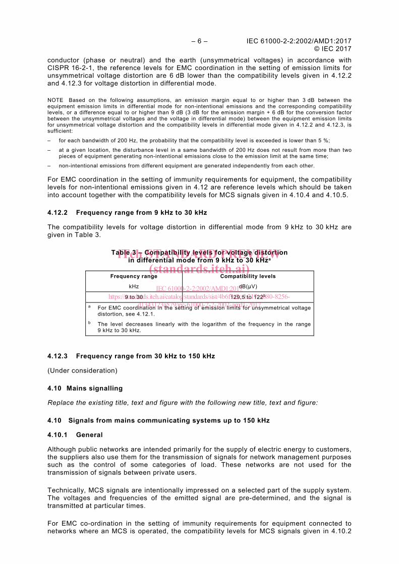
4.12.2 Frequency range from 9 kHz to 30 kHz
The compatibility levels for voltage distortion in differential mode from 9 kHz to 30 kHz are given in Table 3.
Table 3 – Compatibility levels for voltage distortion in differential mode from 9 kHz to 30 kHza
Frequency range Compatibility levels
kHz dB(µV)
9 to 30 129,5 to 122b a For EMC coordination in the setting of emission limits for unsymmetrical voltage
distortion, see 4.12.1. b The level decreases linearly with the logarithm of the frequency in the range
9 kHz to 30 kHz.
4.12.3 Frequency range from 30 kHz to 150 kHz
(Under consideration)
4.10 Mains signalling
Replace the existing title, text and figure with the following new title, text and figure:
4.10 Signals from mains communicating systems up to 150 kHz
4.10.1 General
Although public networks are intended primarily for the supply of electric energy to customers, the suppliers also use them for the transmission of signals for network management purposes such as the control of some categories of load. These networks are not used for the transmission of signals between private users.
Technically, MCS signals are intentionally impressed on a selected part of the supply system. The voltages and frequencies of the emitted signal are pre-determined, and the signal is transmitted at particular times.
For EMC co-ordination in the setting of immunity requirements for equipment connected to networks where an MCS is operated, the compatibility levels for MCS signals given in 4.10.2
iTeh STANDARD PREVIEW(standards.iteh.ai)
IEC 61000-2-2:2002/AMD1:2017https://standards.iteh.ai/catalog/standards/sist/4b6f7a2c-b217-4680-8256-
d1343123a579/iec-61000-2-2-2002-amd1-2017
IEC 61000-2-2:2002/AMD1:2017 – 7 – © IEC 2017 to 4.10.5 are reference levels which should be taken into account together with the compatibility levels for non-intentional emissions defined in 4.3, 4.4, 4.11 and 4.12.
The design of MCSs should meet three objectives:
– ensure compatibility between neighbouring MCSs; – prevent the MCS from being disturbed by other equipment connected to the network; – prevent the MCS from disturbing other equipment connected to the network.
The compatibility levels for MCS signals in the different frequency bands are given in 4.10.2 to 4.10.5.
4.10.2 Ripple control systems (110 Hz to 3 000 Hz)
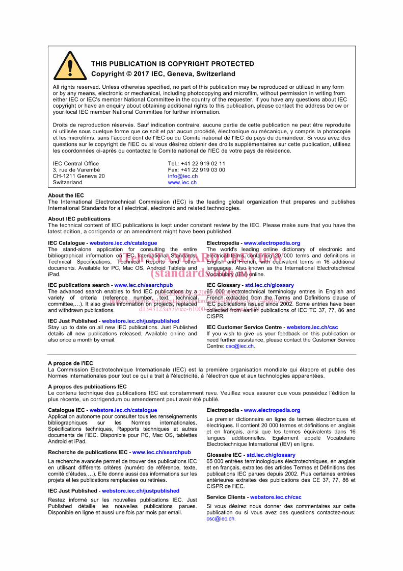
Ripple control signals are transmitted as a sequence of pulses, each pulse having a duration in the range of 0,1 s to 7 s, the duration of the entire sequence ranging from 6 s to 180 s. More usually, the pulse duration is about 0,5 s, and the sequence duration is about 30 s.
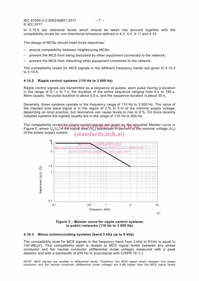
Generally, these systems operate in the frequency range of 110 Hz to 3 000 Hz. The value of the injected sine wave signal is in the region of 2 % to 5 % of the nominal supply voltage, depending on local practice, but resonance can cause levels to rise to 9 %. On more recently installed systems the signals usually are in the range of 110 Hz to 500 Hz.
The compatibility levels for ripple control signals are given by the so-called Meister curve in Figure 3, where Us/Un is the signal level (Us) expressed in percent of the nominal voltage (Un) of the power supply system.
Figure 3 – Meister curve for ripple control systems in public networks (110 Hz to 3 000 Hz)
4.10.3 Mains communicating systems (band 3 kHz up to 9 kHz)
The compatibility level for MCS signals in the frequency band from 3 kHz to 9 kHz is equal to 140 dB(μV). This compatibility level is related to MCS signal levels between any phase conductor and the neutral conductor (differential mode voltage) measured with a peak detector and with a bandwidth of 200 Hz in accordance with CISPR 16-1-1.
NOTE MCS signals are emitted in differential mode. Therefore, the MCS signal levels between one phase conductor and the neutral conductor (differential mode voltage) are 6 dB higher than the MCS signal levels
IEC Frequency (kHz)
Sign
al le
vel:
Us/
Un
(%)
0,1 0,1
0,5 1
1
1,5
10 9
5
3 10
iTeh STANDARD PREVIEW(standards.iteh.ai)
IEC 61000-2-2:2002/AMD1:2017https://standards.iteh.ai/catalog/standards/sist/4b6f7a2c-b217-4680-8256-
d1343123a579/iec-61000-2-2-2002-amd1-2017

– 8 – IEC 61000-2-2:2002/AMD1:2017 © IEC 2017
measured in accordance with IEC 61000-3-8 between any mains conductor (phase or neutral) and the earth (unsymmetrical voltages). As in principle there is only one signal source operating at a given time, the additional emission margin of 3 dB (see the note in 4.12.1) is not necessary here, and the compatibility level in differential mode given in 4.10.3 is just 6 dB higher than the maximum output signal level defined in IEC 61000-3-8.
4.10.4 Mains communicating systems (band 9 kHz up to 95 kHz)
The compatibility level for MCS signals in the frequency band from 9 kHz to 95 kHz is equal to 140 dB(μV) at 9 kHz decreasing linearly with the logarithm of the frequency to 126 dB(μV) at 95 kHz. This compatibility level is related to MCS signal levels between any phase conductor and the neutral conductor (differential mode voltage) measured with a peak detector and with a bandwidth of 200 Hz in accordance with CISPR 16-1-1.
NOTE MCS signals are emitted in differential mode. Therefore, the MCS signal levels between one phase conductor and the neutral conductor (differential mode voltage) are 6 dB higher than the MCS signal levels measured in accordance with IEC 61000-3-8 between any mains conductor (phase or neutral) and the earth (unsymmetrical voltages). As in principle there is only one signal source operating at a given time, the additional emission margin of 3 dB (see the note in 4.12.1) is not necessary here, and the compatibility level in differential mode given in 4.10.4 is just 6 dB higher than the maximum output signal level defined in IEC 61000-3-8.
4.10.5 Mains communicating systems (band 95 kHz up to 150 kHz)
The compatibility level for MCS signals in the frequency band from 95 kHz to 150 kHz is equal to 128 dB(μV). This compatibility level is related to MCS signal levels between any phase conductor and the neutral conductor (differential mode voltage) measured with a peak detector and with a bandwidth of 200 Hz in accordance with CISPR 16-1-1.
NOTE 1 MCS signals are emitted in differential mode. Therefore, the MCS signal levels between one phase conductor and the neutral conductor (differential mode voltage) are 6 dB higher than the MCS signal levels measured in accordance with IEC 61000-3-8 between any mains conductor (phase or neutral) and the earth (unsymmetrical voltages). As in principle there is only one signal source operating at a given time in the same bandwidth of 200 Hz, the additional emission margin of 3 dB (see the note in 4.12.1) is not necessary here, and the compatibility level in differential mode given in 4.10.5 is just 6 dB higher than the maximum output signal level defined in EN 50065-1.
NOTE 2 The frequency band from 95 kHz to 150 kHz consists of three sub-bands, 95 kHz to 125 kHz, 125 kHz to 140 kHz and 140 kHz to 150 kHz, with different signal requirements.
iTeh STANDARD PREVIEW(standards.iteh.ai)
IEC 61000-2-2:2002/AMD1:2017https://standards.iteh.ai/catalog/standards/sist/4b6f7a2c-b217-4680-8256-
d1343123a579/iec-61000-2-2-2002-amd1-2017
IEC 61000-2-2:2002/AMD1:2017 – 9 – © IEC 2017
Annex B
B.2 Interharmonics and voltage components at frequencies above that of the 50th harmonic
Replace the existing title, text and table with the following new title, text and table:
B.2 Interharmonics
B.2.1 Sources of interharmonic currents and voltages
The public a.c. distribution systems are intended to deliver voltages at the power frequency of 50 Hz or 60 Hz. The presence of voltages at other frequencies is, as far as possible, to be avoided. However, modern developments in electricity utilisation tend to increase the superposition on the supply voltage of voltages at unwanted frequencies. An increasingly important source of the unintended frequencies is the electronic power conditioning modules which are increasingly being incorporated in electricity utilisation devices.
The following are typical sources:
– Most electronic components require a d.c. supply. In the absence of or as an alternative to batteries or other d.c. supply, the common practice is to provide an electronic module that extracts the required energy from the a.c. supply and delivers it to the components by way of a d.c. voltage. The switched mode power supply is the most common device used for this purpose. The result, however, is that power is drawn from the a.c. system in a highly non-linear manner, resulting in currents at many harmonic and interharmonic frequencies, extending even to frequencies beyond that of the 40th harmonic. As these currents flow through the impedances of the supply system, they give rise to voltages at the corresponding frequencies, and these, in turn, are superimposed on the supply voltage delivered to users.
– In some cases the end-use of the electricity requires an a.c. voltage at a frequency other than the supply frequency, as in variable or adjustable speed drive systems. Again, this is accomplished by electronic devices that extract the required energy from the incoming supply and deliver it to the downstream components by way of a voltage at the required frequency. Viewed from the supply system, these devices are sources of current at many frequencies in addition to the supply frequency. While harmonic frequencies are generally prevalent, some types of converters produce interharmonics in addition. Voltage source inverters, with pulse duration (width) modulated converters on the network side, produce harmonics of the modulation frequency, which has no synchronism with the network frequency. These are mainly at higher frequencies: switching frequency and its harmonics. High power equipment, typically above 1 MW and connected to a medium or high voltage power network, can use inverters, operated at any frequency without synchronism with the network frequency. They can produce interharmonics due to residual coupling between the motor side and the network. As a general result, sources such as electronic frequency converters can produce discrete frequencies in the range of 0 Hz to 2 000 Hz (50 Hz systems) or 2 400 Hz (60 Hz systems). (See IEC 61000-2-4, Annex C.)
– Electrical arc-furnaces can be a source of a large amount of interharmonics. This is also high power equipment, which would not be connected to a public low voltage power network.
– Arc welding machines generate a continuous wide band frequency spectrum, associated with an intermittent process in which the duration of the individual welding actions varies between a second and several seconds.
– Induction motors can give rise to an irregular magnetising current due to the slots in the stator and rotor, possibly in association with saturation of the iron. At the normal speed of the motor, this generates interharmonics at frequencies between 10 to 40 times the power
iTeh STANDARD PREVIEW(standards.iteh.ai)
IEC 61000-2-2:2002/AMD1:2017https://standards.iteh.ai/catalog/standards/sist/4b6f7a2c-b217-4680-8256-
d1343123a579/iec-61000-2-2-2002-amd1-2017

– 10 – IEC 61000-2-2:2002/AMD1:2017 © IEC 2017
frequency, but during the starting period they run through the whole frequency range up to their final value.
– Power supplies to traction systems can result in interharmonics at fixed frequencies, for example 16,7 Hz.
Sources such as the above are connected to networks of low, medium and high voltage. Their emissions result in interharmonic voltages which are generated in and transmitted between all voltage levels and depend on the network impedances.
Mains signalling is also a source of interharmonic voltages, but in this case the emissions are intentional and utilities and users exercise careful control to ensure compatibility (see 4.10).
B.2.2 Effects of the interharmonic voltages
The case of a voltage having a frequency which combines with the fundamental frequency and results in a beat frequency has been dealt with in 4.4. Table B.1 indicates the interharmonic voltage levels corresponding to the compatibility level given in Figure 2.
Table B.1 – Indicative values of interharmonic voltage in low voltage networks corresponding to the compatibility level with respect to the flicker effect
Order m
50 Hz system 60 Hz system
Interharmonic frequency
fm Hz
Um %
Interharmonic frequency
fm Hz
Um %
120 V system
230 V system
120 V system
230 V system
0,2 < m ≤ 0,6 10 < fm ≤ 30 0,68 0,51 12 < fm ≤ 36 0,95 0,69
0,60 < m ≤ 0,64 30 < fm ≤ 32 0,57 0,43 36 < fm ≤ 38,4 0,79 0,58
0,64 < m ≤ 0,68 32 < fm ≤ 34 0,46 0,35 38,4 < fm ≤ 40,8 0,64 0,48
0,68 < m ≤ 0,72 34 < fm ≤ 36 0,37 0,28 40,8 < fm ≤ 43,2 0,50 0,38
0,72 < m ≤ 0,76 36 < fm ≤ 38 0,29 0,23 43,2 < fm ≤ 45,6 0,39 0,30
0,76 < m ≤ 0,84 38 < fm ≤ 42 0,23 0,18 45,6 < fm ≤ 50,4 0,23 0,18
0,84 < m ≤ 0,88 42 < fm ≤ 44 0,23 0,18 50,4 < fm ≤ 52,8 0,22 0,18
0,88 < m ≤ 0,92 44 < fm ≤ 46 0,28 0,24 52,8 < fm ≤ 55,2 0,22 0,20
0,92 < m ≤ 0,96 46 < fm ≤ 48 0,40 0,36 55,2 < fm ≤ 57,6 0,34 0,30
0,96 < m < 1,04 48 < fm ≤ 52 0,67 0,64 57,6 < fm ≤ 62,4 0,59 0,56
1,04 < m ≤ 1,08 52 < fm ≤ 54 0,40 0,36 62,4 < fm ≤ 64,8 0,34 0,30
1,08 < m ≤ 1,12 54 < fm ≤ 56 0,28 0,24 64,8 < fm ≤ 67,2 0,22 0,20
1,12 < m ≤ 1,16 56 < fm ≤ 58 0,23 0,18 67,2 < fm ≤ 69,6 0,22 0,18
1,16 < m ≤ 1,24 58 < fm ≤ 62 0,23 0,18 69,6 < fm ≤ 74,4 0,23 0,18
1,24 < m ≤ 1,28 62 < fm ≤ 64 0,29 0,23 74,4 < fm ≤ 76,8 0,39 0,30
1,28 < m ≤ 1,32 64 < fm ≤ 66 0,37 0,28 76,8 < fm ≤ 79.2 0,50 0,38
1,32 < m ≤ 1,36 66 < fm ≤ 68 0,46 0,35 79,2 < fm ≤ 81,6 0,64 0,48
1,36 < m ≤ 1,40 68 < fm ≤ 70 0,57 0,43 81,6 < fm ≤ 84 0,79 0,58
1,4 < m ≤ 1,8 70 < fm ≤ 90 0,68 0,51 84 < fm ≤ 108 0,95 0,69
Some other effects of interharmonics include:
– unwanted currents flowing in the supply networks generate additional energy losses, with a consequent increase in the gaseous emissions from generating stations;
iTeh STANDARD PREVIEW(standards.iteh.ai)
IEC 61000-2-2:2002/AMD1:2017https://standards.iteh.ai/catalog/standards/sist/4b6f7a2c-b217-4680-8256-
d1343123a579/iec-61000-2-2-2002-amd1-2017