Embed Size (px)
Citation preview
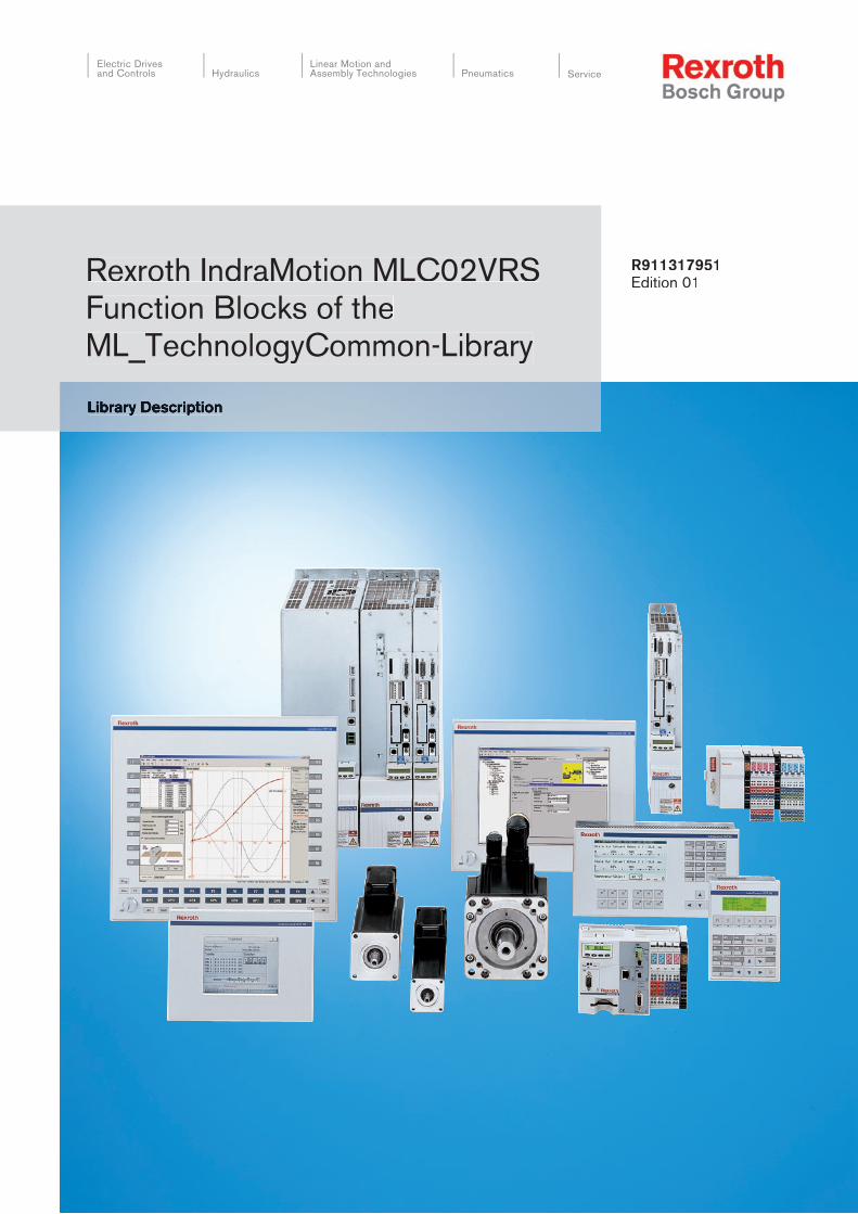
Rexroth IndraMotion MLC02VRSFunction Blocks of theML_TechnologyCommon-Library
R911317951Edition 01
Electric Drivesand Controls Pneumatics Service
Linear Motion and Assembly TechnologiesHydraulics
Library Description
Rexroth IndraMotion MLC02VRSFunction Blocks of theML_TechnologyCommon-Library
Library Description
DOK-IM*MLC-TECHCOM*V02-AW01-EN-P
RS-48ad7c6a0a6846ac006a64df6e623dad-1-en-US-3
The documentation describes the function blocks, functions and data types ofthe “ML_TechnologyCommon”-Library in the version for the IndraMotionMLC02VRS.In addition it contains details on the error reactions of the blocks.
Edition Release Date Notes
DOK-IM*MLC-TECHCOM*V02-AW01-EN-P
06.2006 First edition, MLC02VRS
© 2006 Bosch Rexroth AGCopying this document, giving it to others and the use or communication of thecontents therof without express authourity, are forbidden. Offenders are liablefor the payment of damages. All rights are reserved in the event of the grant ofa patent or the registration of a utility model or design (DIN 34-1).The specified data is for product description purposes only and may not bedeemed to be guaranteed unless expressly confirmed in the contract. All rightsare reserved with respect to the content of this documentation and the availa‐bility of the product.Bosch Rexroth AGBgm.-Dr.-Nebel-Str. 2 • D-97816 Lohr a. MainPhone +49 (0)93 52 / 40-0 • Fax +49 (0)93 52 / 40-48 85http://www.boschrexroth.com/Dept. BRC/ESC (vha)This document has been printed on chlorine-free bleached paper.
Title
Type of Documentation
Document Typecode
Internal File Reference
Purpose of Documentation
Record of Revision
Copyright
Validity
Publisher
Note
Bosch Rexroth AG | Electric Drivesand Controls
Rexroth IndraMotion MLC02VRS | Library Description
Table of ContentsPage
1 Technology Function Blocks of Library ML_TechnologyCommon................................. 11.1 Introduction and Overview ..................................................................................................................... 11.2 Further Documentation .......................................................................................................................... 11.3 General Definitions................................................................................................................................. 21.4 Function Blocks for Application “Cam Blocks” ....................................................................................... 31.4.1 Introduction and Overview................................................................................................................... 31.4.2 ML_CamTableType01 ........................................................................................................................ 31.4.3 ML_CamTableType02 ........................................................................................................................ 81.4.4 ML_CamTableType03 ...................................................................................................................... 121.4.5 ML_CamTableType04 ...................................................................................................................... 171.4.6 ML_CamTableType05 ...................................................................................................................... 221.4.7 ML_CamTableType06 ...................................................................................................................... 261.4.8 ML_CamTableType07 ...................................................................................................................... 301.4.9 ML_CamTableType08 ...................................................................................................................... 331.4.10 ML_CamTableType09 ...................................................................................................................... 371.4.11 ML_CamTableType10 ...................................................................................................................... 411.4.12 ML_CamTableType11 ...................................................................................................................... 451.4.13 ML_CamTableType12 ...................................................................................................................... 501.5 Function Blocks for Application “Cam Switch” ..................................................................................... 561.5.1 Introduction and Overview................................................................................................................. 561.5.2 MC_CAMSWITCH_REF with ML_BASIC_CAMSWITCH_REF ........................................................ 561.5.3 MC_TRACK_REF with ML_BASIC_TRACK_REF ............................................................................ 571.5.4 MC_OUTPUT_REF .......................................................................................................................... 571.5.5 MC_DigitalCamSwitch ...................................................................................................................... 571.6 Function Blocks for Application “PID-Controller” ................................................................................. 711.6.1 Introduction and Overview................................................................................................................. 711.6.2 ML_PIDType01 ................................................................................................................................. 711.7 Function Blocks for Application “Safe Key Transmission” ................................................................... 751.7.1 Introduction and Overview................................................................................................................. 751.7.2 ML_SafeKeystroke ........................................................................................................................... 75
2 Service & Support........................................................................................................ 772.1 Helpdesk............................................................................................................................................... 772.2 Service Hotline...................................................................................................................................... 772.3 Internet.................................................................................................................................................. 772.4 Helpful Information................................................................................................................................ 77
Index............................................................................................................................ 79
Library Description | Rexroth IndraMotion MLC02VRS Electric Drivesand Controls
| Bosch Rexroth AG I/I
Table of Contents

Bosch Rexroth AG | Electric Drivesand Controls
Rexroth IndraMotion MLC02VRS | Library Description
1 Technology Function Blocks of Library ML_Technolo‐gyCommon
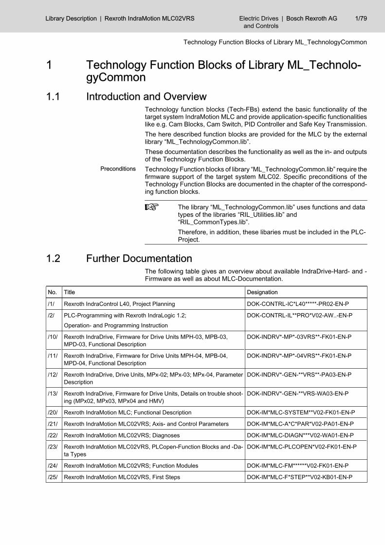
1.1 Introduction and OverviewTechnology function blocks (Tech-FBs) extend the basic functionality of thetarget system IndraMotion MLC and provide application-specific functionalitieslike e.g. Cam Blocks, Cam Switch, PID Controller and Safe Key Transmission.The here described function blocks are provided for the MLC by the externallibrary “ML_TechnologyCommon.lib”.These documentation describes the functionality as well as the in- and outputsof the Technology Function Blocks.Technology Function blocks of library “ML_TechnologyCommon.lib” require thefirmware support of the target system MLC02. Specific preconditions of theTechnology Function Blocks are documented in the chapter of the correspond‐ing function blocks.
The library “ML_TechnologyCommon.lib” uses functions and datatypes of the libraries “RIL_Utilities.lib” and“RIL_CommonTypes.lib”.Therefore, in addition, these libaries must be included in the PLC-Project.
1.2 Further DocumentationThe following table gives an overview about available IndraDrive-Hard- and -Firmware as well as about MLC-Documentation.
No. Title Designation
/1/ Rexroth IndraControl L40, Project Planning DOK-CONTRL-IC*L40*****-PR02-EN-P
/2/ PLC-Programming with Rexroth IndraLogic 1.2;
Operation- and Programming Instruction
DOK-CONTRL-IL**PRO*V02-AW..-EN-P
/10/ Rexroth IndraDrive, Firmware for Drive Units MPH-03, MPB-03,MPD-03, Functional Description
DOK-INDRV*-MP*-03VRS**-FK01-EN-P
/11/ Rexroth IndraDrive, Firmware for Drive Units MPH-04, MPB-04,MPD-04, Functional Description
DOK-INDRV*-MP*-04VRS**-FK01-EN-P
/12/ Rexroth IndraDrive, Drive Units, MPx-02; MPx-03; MPx-04, ParameterDescription
DOK-INDRV*-GEN-**VRS**-PA03-EN-P
/13/ Rexroth IndraDrive, Firmware for Drive Units, Details on trouble shoot‐ing (MPx02, MPx03, MPx04 and HMV)
DOK-INDRV*-GEN-**VRS-WA03-EN-P
/20/ Rexroth IndraMotion MLC; Functional Description DOK-IM*MLC-SYSTEM**V02-FK01-EN-P
/21/ Rexroth IndraMotion MLC02VRS; Axis- and Control Parameters DOK-IM*MLC-A*C*PAR*V02-PA01-EN-P
/22/ Rexroth IndraMotion MLC02VRS; Diagnoses DOK-IM*MLC-DIAGN***V02-WA01-EN-P
/23/ Rexroth IndraMotion MLC02VRS, PLCopen-Function Blocks and -Da‐ta Types
DOK-IM*MLC-PLCOPEN*V02-FK01-EN-P
/24/ Rexroth IndraMotion MLC02VRS; Function Modules DOK-IM*MLC-FM******V02-FK01-EN-P
/25/ Rexroth IndraMotion MLC02VRS, First Steps DOK-IM*MLC-F*STEP**V02-KB01-EN-P
Preconditions
Library Description | Rexroth IndraMotion MLC02VRS Electric Drivesand Controls
| Bosch Rexroth AG 1/79
Technology Function Blocks of Library ML_TechnologyCommon
No. Title Designation
/30/ Rexroth IndraMotion MLC02VRS, Technology Function Blocks of Li‐brary ML_TechnologyCommon
DOK-IM*MLC-TECHCOM*V02-AW01-EN-P
/31/ Rexroth IndraMotion MLC02VRS, Technology Function Blocks of Li‐brary ML_Technology
DOK-IM*MLC-TECHFB**V02-AW01-EN-P
Fig.1-1: Further Documentation
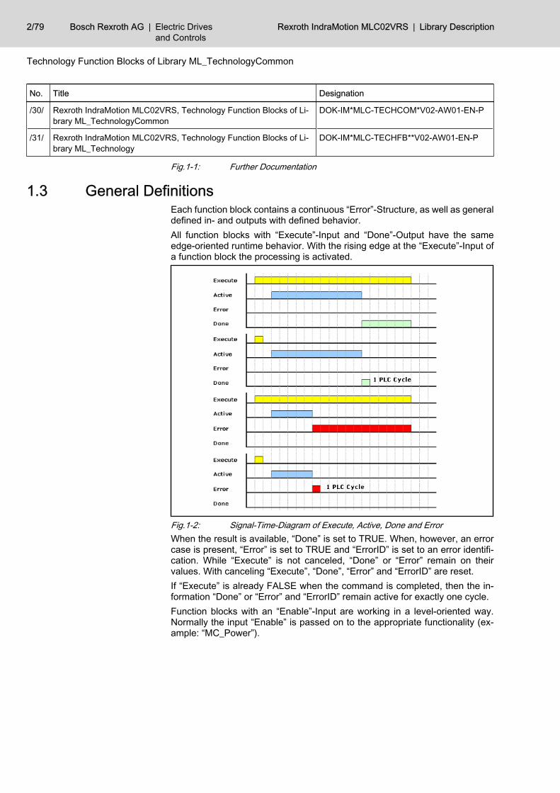
1.3 General DefinitionsEach function block contains a continuous “Error”-Structure, as well as generaldefined in- and outputs with defined behavior.All function blocks with “Execute”-Input and “Done”-Output have the sameedge-oriented runtime behavior. With the rising edge at the “Execute”-Input ofa function block the processing is activated.
Fig.1-2: Signal-Time-Diagram of Execute, Active, Done and ErrorWhen the result is available, “Done” is set to TRUE. When, however, an errorcase is present, “Error” is set to TRUE and “ErrorID” is set to an error identifi‐cation. While “Execute” is not canceled, “Done” or “Error” remain on theirvalues. With canceling “Execute”, “Done”, “Error” and “ErrorID” are reset.If “Execute” is already FALSE when the command is completed, then the in‐formation “Done” or “Error” and “ErrorID” remain active for exactly one cycle.Function blocks with an “Enable”-Input are working in a level-oriented way.Normally the input “Enable” is passed on to the appropriate functionality (ex‐ample: “MC_Power”).
2/79 Bosch Rexroth AG | Electric Drivesand Controls
Rexroth IndraMotion MLC02VRS | Library Description
Technology Function Blocks of Library ML_TechnologyCommon
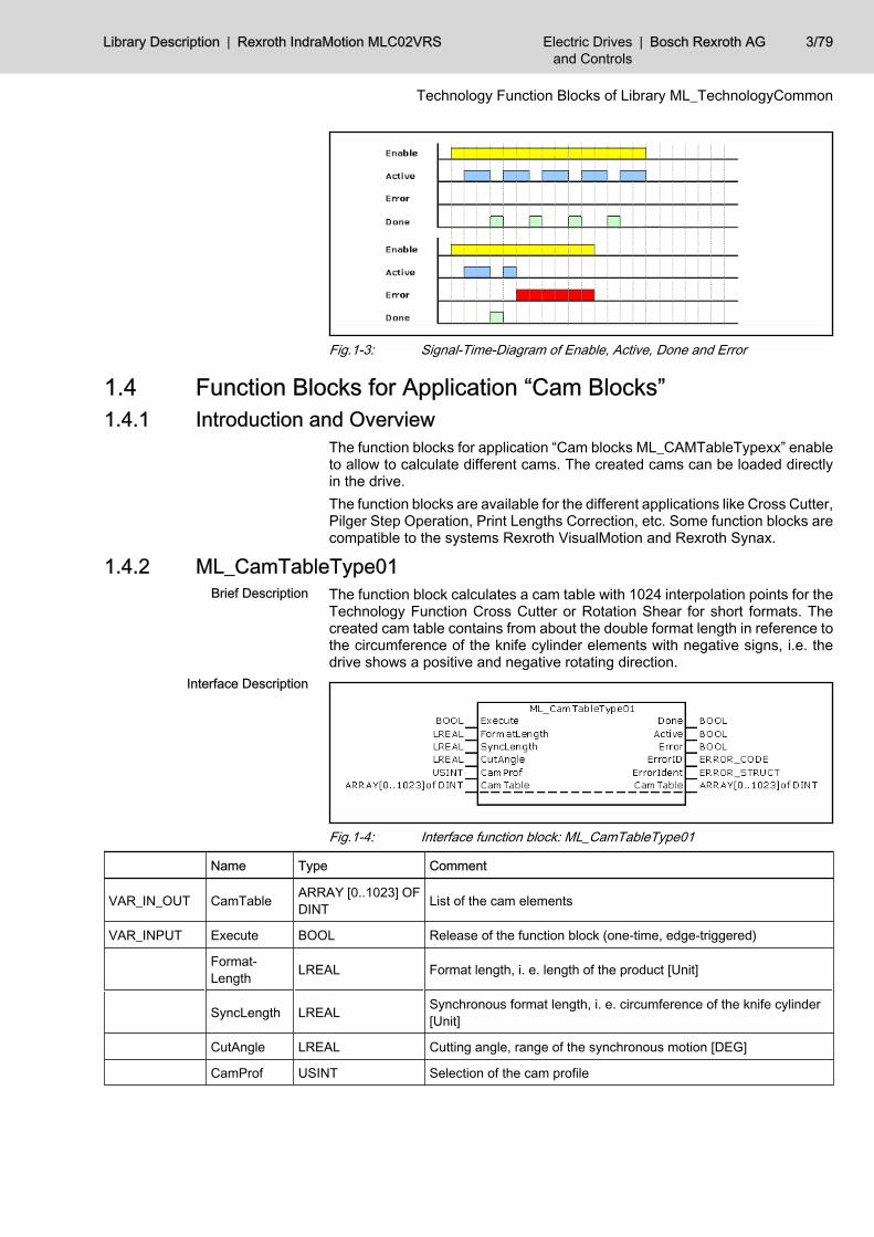
Fig.1-3: Signal-Time-Diagram of Enable, Active, Done and Error
1.4 Function Blocks for Application “Cam Blocks” 1.4.1 Introduction and Overview
The function blocks for application “Cam blocks ML_CAMTableTypexx” enableto allow to calculate different cams. The created cams can be loaded directlyin the drive.The function blocks are available for the different applications like Cross Cutter,Pilger Step Operation, Print Lengths Correction, etc. Some function blocks arecompatible to the systems Rexroth VisualMotion and Rexroth Synax.
1.4.2 ML_CamTableType01The function block calculates a cam table with 1024 interpolation points for theTechnology Function Cross Cutter or Rotation Shear for short formats. Thecreated cam table contains from about the double format length in reference tothe circumference of the knife cylinder elements with negative signs, i.e. thedrive shows a positive and negative rotating direction.
Fig.1-4: Interface function block: ML_CamTableType01
Name Type Comment
VAR_IN_OUT CamTable ARRAY [0..1023] OFDINT List of the cam elements
VAR_INPUT Execute BOOL Release of the function block (one-time, edge-triggered)
Format‐Length LREAL Format length, i. e. length of the product [Unit]
SyncLength LREAL Synchronous format length, i. e. circumference of the knife cylinder[Unit]
CutAngle LREAL Cutting angle, range of the synchronous motion [DEG]
CamProf USINT Selection of the cam profile
Brief Description
Interface Description
Library Description | Rexroth IndraMotion MLC02VRS Electric Drivesand Controls
| Bosch Rexroth AG 3/79
Technology Function Blocks of Library ML_TechnologyCommon
Name Type Comment
VAR_OUTPUT Done BOOL Calculation of the cam elements completed without error, list of thecam elements is valid
Active BOOL Calculation of the cam elements is active, list of the cam elements isinvalid
Error BOOL Calculation of the cam elements completed with error, list of the camelements is invalid
ErrorID ERROR_CODE With set “Error”-Output this output contains a rough classification ofthe error
ErrorIdent ERROR_STRUCT With set “Error”-Output this output contains detailed information aboutthe error
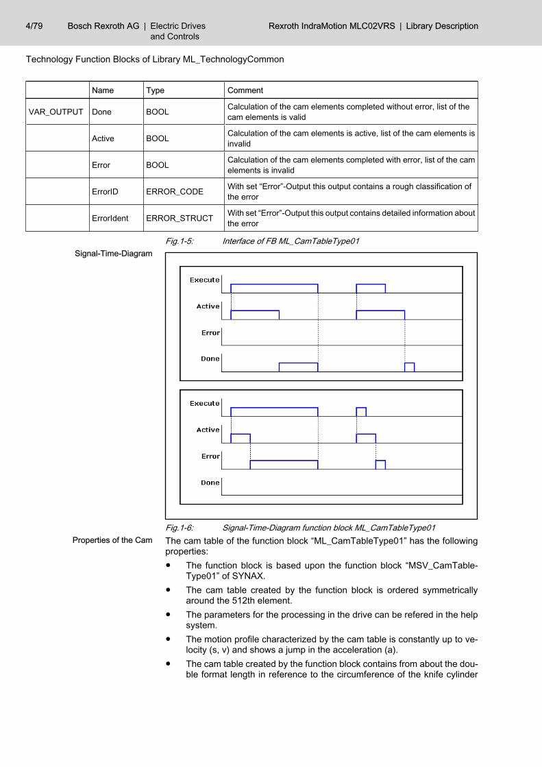
Fig.1-5: Interface of FB ML_CamTableType01
Fig.1-6: Signal-Time-Diagram function block ML_CamTableType01The cam table of the function block “ML_CamTableType01” has the followingproperties:● The function block is based upon the function block “MSV_CamTable‐
Type01” of SYNAX.● The cam table created by the function block is ordered symmetrically
around the 512th element.● The parameters for the processing in the drive can be refered in the help
system.● The motion profile characterized by the cam table is constantly up to ve‐
locity (s, v) and shows a jump in the acceleration (a).● The cam table created by the function block contains from about the dou‐
ble format length in reference to the circumference of the knife cylinder
Signal-Time-Diagram
Properties of the Cam
4/79 Bosch Rexroth AG | Electric Drivesand Controls
Rexroth IndraMotion MLC02VRS | Library Description
Technology Function Blocks of Library ML_TechnologyCommon
elements with negative signs, i.e. the drive shows a positive and negativerotating direction.
● The function block can create cam profiles for ELS05 (CamProf == 0) aswell as for ELS06 (CamProf == 1) of the drive.
● The algorithm for calculating the cam interpolation points is shared onmax. 33 cycles, i.e. calls of the instance, to avoid a noticeable influenceon the cycle time of the PLC.
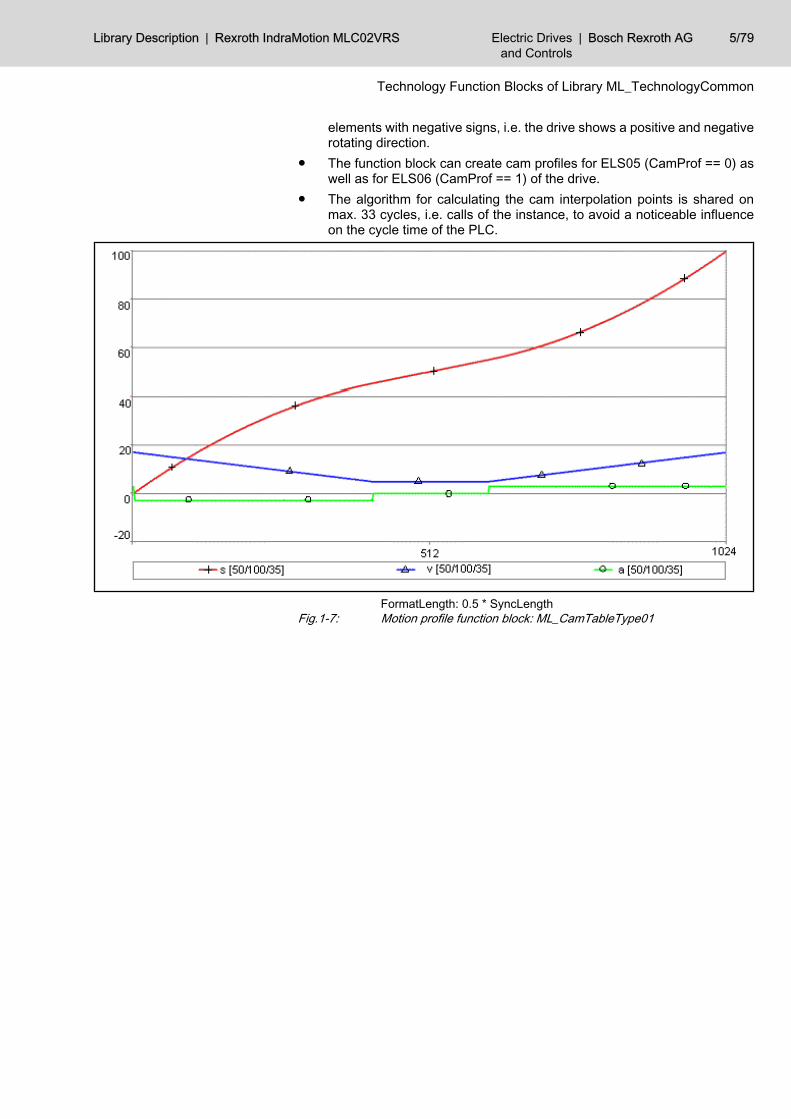
FormatLength: 0.5 * SyncLengthFig.1-7: Motion profile function block: ML_CamTableType01
Library Description | Rexroth IndraMotion MLC02VRS Electric Drivesand Controls
| Bosch Rexroth AG 5/79
Technology Function Blocks of Library ML_TechnologyCommon
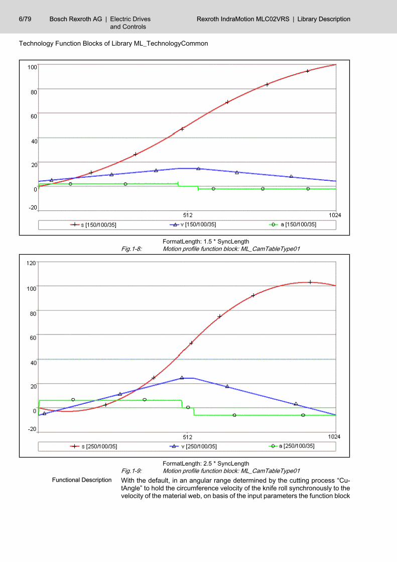
FormatLength: 1.5 * SyncLengthFig.1-8: Motion profile function block: ML_CamTableType01
FormatLength: 2.5 * SyncLengthFig.1-9: Motion profile function block: ML_CamTableType01With the default, in an angular range determined by the cutting process “Cu‐tAngle” to hold the circumference velocity of the knife roll synchronously to thevelocity of the material web, on basis of the input parameters the function block
Functional Description
6/79 Bosch Rexroth AG | Electric Drivesand Controls
Rexroth IndraMotion MLC02VRS | Library Description
Technology Function Blocks of Library ML_TechnologyCommon
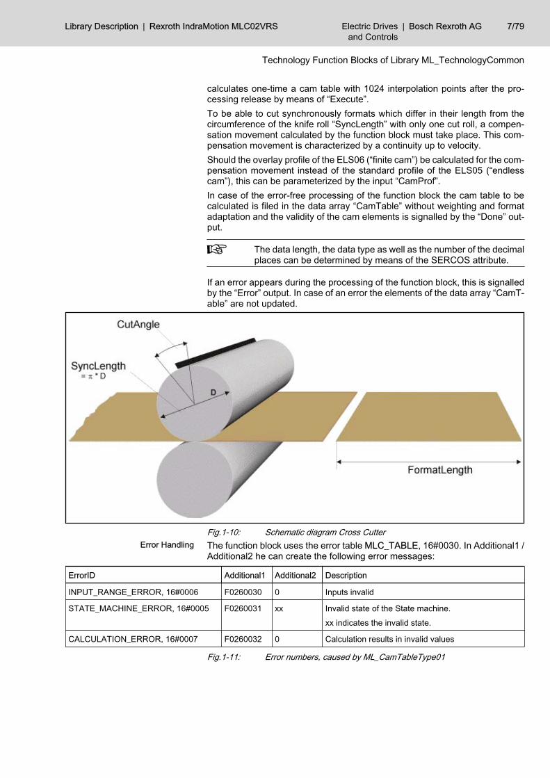
calculates one-time a cam table with 1024 interpolation points after the pro‐cessing release by means of “Execute”.To be able to cut synchronously formats which differ in their length from thecircumference of the knife roll “SyncLength” with only one cut roll, a compen‐sation movement calculated by the function block must take place. This com‐pensation movement is characterized by a continuity up to velocity.Should the overlay profile of the ELS06 (“finite cam”) be calculated for the com‐pensation movement instead of the standard profile of the ELS05 (“endlesscam”), this can be parameterized by the input “CamProf”.In case of the error-free processing of the function block the cam table to becalculated is filed in the data array “CamTable” without weighting and formatadaptation and the validity of the cam elements is signalled by the “Done” out‐put.
The data length, the data type as well as the number of the decimalplaces can be determined by means of the SERCOS attribute.
If an error appears during the processing of the function block, this is signalledby the “Error” output. In case of an error the elements of the data array “CamT‐able” are not updated.
Fig.1-10: Schematic diagram Cross CutterThe function block uses the error table MLC_TABLE, 16#0030. In Additional1 /Additional2 he can create the following error messages:
ErrorID Additional1 Additional2 Description
INPUT_RANGE_ERROR, 16#0006 F0260030 0 Inputs invalid
STATE_MACHINE_ERROR, 16#0005 F0260031 xx Invalid state of the State machine.
xx indicates the invalid state.
CALCULATION_ERROR, 16#0007 F0260032 0 Calculation results in invalid values
Fig.1-11: Error numbers, caused by ML_CamTableType01
Error Handling
Library Description | Rexroth IndraMotion MLC02VRS Electric Drivesand Controls
| Bosch Rexroth AG 7/79
Technology Function Blocks of Library ML_TechnologyCommon
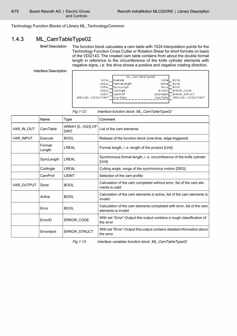
1.4.3 ML_CamTableType02The function block calculates a cam table with 1024 interpolation points for theTechnology Function Cross Cutter or Rotation Shear for short formats on basisof the VDI2143. The created cam table contains from about the double formatlength in reference to the circumference of the knife cylinder elements withnegative signs, i.e. the drive shows a positive and negative rotating direction.
Fig.1-12: Interface function block: ML_CamTableType02
Name Type Comment
VAR_IN_OUT CamTable ARRAY [0..1023] OFDINT List of the cam elements
VAR_INPUT Execute BOOL Release of the function block (one-time, edge-triggered)
Format‐Length LREAL Format length, i. e. length of the product [Unit]
SyncLength LREAL Synchronous format length, i. e. circumference of the knife cylinder[Unit]
CutAngle LREAL Cutting angle, range of the synchronous motion [DEG]
CamProf USINT Selection of the cam profile
VAR_OUTPUT Done BOOL Calculation of the cam completed without error, list of the cam ele‐ments is valid
Active BOOL Calculation of the cam elements is active, list of the cam elements isinvalid
Error BOOL Calculation of the cam elements completed with error, list of the camelements is invalid
ErrorID ERROR_CODE With set “Error”-Output this output contains a rough classification ofthe error
ErrorIdent ERROR_STRUCT With set “Error”-Output this output contains detailed information aboutthe error
Fig.1-13: Interface variables function block: ML_CamTableType02
Brief Description
Interface Description
8/79 Bosch Rexroth AG | Electric Drivesand Controls
Rexroth IndraMotion MLC02VRS | Library Description
Technology Function Blocks of Library ML_TechnologyCommon
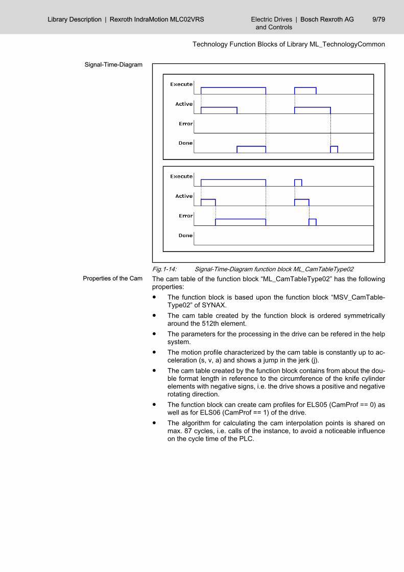
Fig.1-14: Signal-Time-Diagram function block ML_CamTableType02The cam table of the function block “ML_CamTableType02” has the followingproperties:● The function block is based upon the function block “MSV_CamTable‐
Type02” of SYNAX.● The cam table created by the function block is ordered symmetrically
around the 512th element.● The parameters for the processing in the drive can be refered in the help
system.● The motion profile characterized by the cam table is constantly up to ac‐
celeration (s, v, a) and shows a jump in the jerk (j).● The cam table created by the function block contains from about the dou‐
ble format length in reference to the circumference of the knife cylinderelements with negative signs, i.e. the drive shows a positive and negativerotating direction.
● The function block can create cam profiles for ELS05 (CamProf == 0) aswell as for ELS06 (CamProf == 1) of the drive.
● The algorithm for calculating the cam interpolation points is shared onmax. 87 cycles, i.e. calls of the instance, to avoid a noticeable influenceon the cycle time of the PLC.
Signal-Time-Diagram
Properties of the Cam
Library Description | Rexroth IndraMotion MLC02VRS Electric Drivesand Controls
| Bosch Rexroth AG 9/79
Technology Function Blocks of Library ML_TechnologyCommon
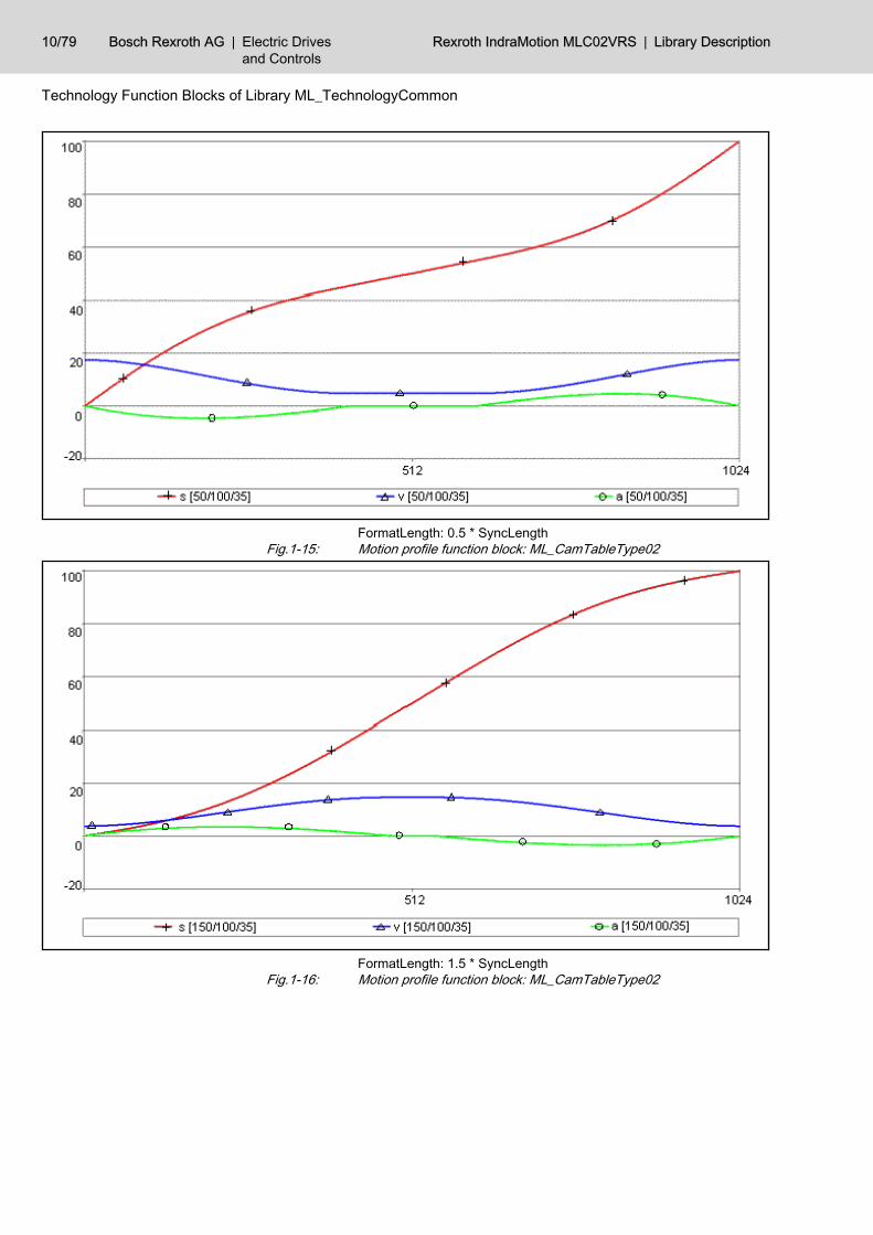
FormatLength: 0.5 * SyncLengthFig.1-15: Motion profile function block: ML_CamTableType02
FormatLength: 1.5 * SyncLengthFig.1-16: Motion profile function block: ML_CamTableType02
10/79 Bosch Rexroth AG | Electric Drivesand Controls
Rexroth IndraMotion MLC02VRS | Library Description
Technology Function Blocks of Library ML_TechnologyCommon
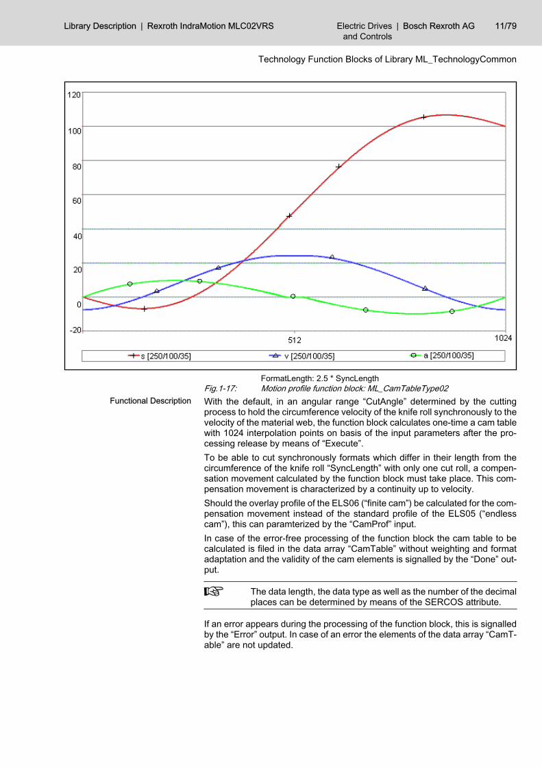
FormatLength: 2.5 * SyncLengthFig.1-17: Motion profile function block: ML_CamTableType02With the default, in an angular range “CutAngle” determined by the cuttingprocess to hold the circumference velocity of the knife roll synchronously to thevelocity of the material web, the function block calculates one-time a cam tablewith 1024 interpolation points on basis of the input parameters after the pro‐cessing release by means of “Execute”.To be able to cut synchronously formats which differ in their length from thecircumference of the knife roll “SyncLength” with only one cut roll, a compen‐sation movement calculated by the function block must take place. This com‐pensation movement is characterized by a continuity up to velocity.Should the overlay profile of the ELS06 (“finite cam”) be calculated for the com‐pensation movement instead of the standard profile of the ELS05 (“endlesscam”), this can paramterized by the “CamProf” input.In case of the error-free processing of the function block the cam table to becalculated is filed in the data array “CamTable” without weighting and formatadaptation and the validity of the cam elements is signalled by the “Done” out‐put.
The data length, the data type as well as the number of the decimalplaces can be determined by means of the SERCOS attribute.
If an error appears during the processing of the function block, this is signalledby the “Error” output. In case of an error the elements of the data array “CamT‐able” are not updated.
Functional Description
Library Description | Rexroth IndraMotion MLC02VRS Electric Drivesand Controls
| Bosch Rexroth AG 11/79
Technology Function Blocks of Library ML_TechnologyCommon
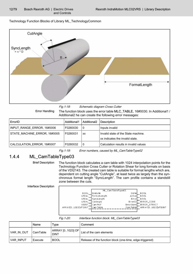
Fig.1-18: Schematic diagram Cross CutterThe function block uses the error table MLC_TABLE, 16#0030. In Additional1 /Additional2 he can create the following error messages:
ErrorID Additional1 Additional2 Description
INPUT_RANGE_ERROR, 16#0006 F0260030 0 Inputs invalid
STATE_MACHINE_ERROR, 16#0005 F0260031 xx Invalid state of the State machine.
xx indicates the invalid state.
CALCULATION_ERROR, 16#0007 F0260032 0 Calculation results in invalid values
Fig.1-19: Error numbers, caused by ML_CamTableType02
1.4.4 ML_CamTableType03The function block calculates a cam table with 1024 interpolation points for theTechnology Function Cross Cutter or Rotation Shear for long formats on basisof the VDI2143. The created cam table is suitable for format lengths which are,dependent on cutting angle “CutAngle”, at least twice as largely than the syn‐chronous format length “SyncLength”. The cam profile contains a standstillzone between the cuts.
Fig.1-20: Interface function block: ML_CamTableType03
Name Type Comment
VAR_IN_OUT CamTable ARRAY [0..1023] OFDINT List of the cam elements
VAR_INPUT Execute BOOL Release of the function block (one-time, edge-triggered)
Error Handling
Brief Description
Interface Description
12/79 Bosch Rexroth AG | Electric Drivesand Controls
Rexroth IndraMotion MLC02VRS | Library Description
Technology Function Blocks of Library ML_TechnologyCommon
Name Type Comment
Format‐Length LREAL Format length, i. e. length of the product [Unit]
SyncLength LREAL Synchronous format length, i. e. circumference of the knife cylinder[Unit]
CutAngle LREAL Cutting angle, range of the synchronous motion [DEG]
CamProf USINT Selection of the cam profile
VAR_OUTPUT Done BOOL Calculation of the cam completed without error, list of the cam ele‐ments is valid
Active BOOL Calculation of the cam elements is active, list of the cam elements isinvalid
Error BOOL Calculation of the cam elements completed with error, list of the camelements is invalid
ErrorID ERROR_CODE With set “Error”-Output this output contains a rough classification ofthe error
ErrorIdent ERROR_STRUCT With set “Error”-Output this output contains detailed information aboutthe error
Fig.1-21: Interface variables function block: ML_CamTableType03
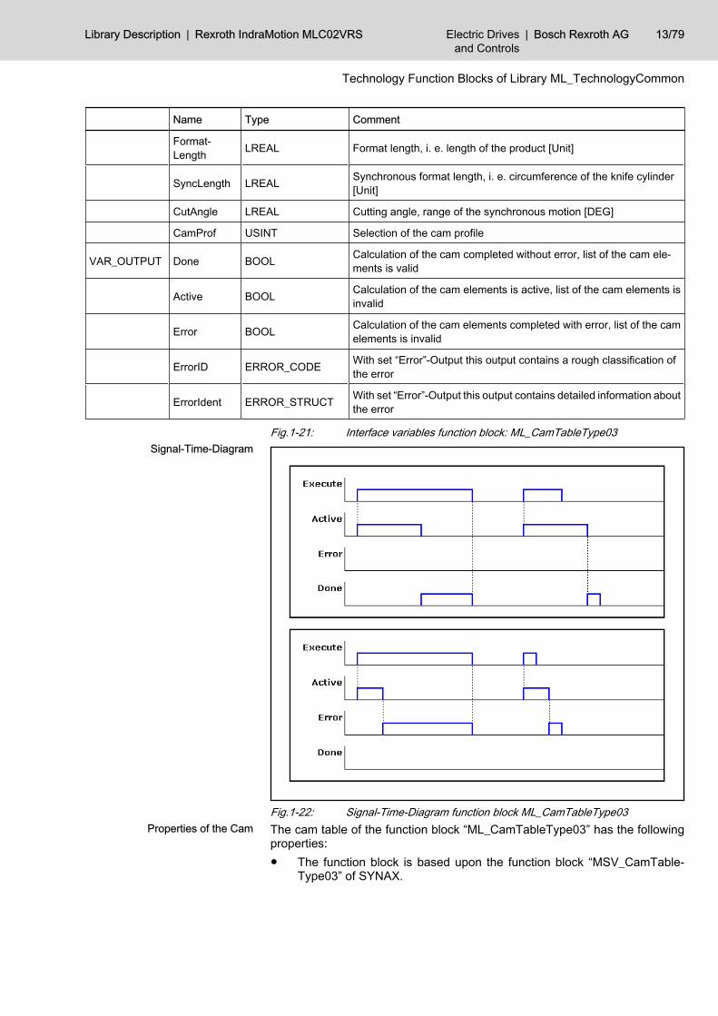
Fig.1-22: Signal-Time-Diagram function block ML_CamTableType03The cam table of the function block “ML_CamTableType03” has the followingproperties:● The function block is based upon the function block “MSV_CamTable‐
Type03” of SYNAX.
Signal-Time-Diagram
Properties of the Cam
Library Description | Rexroth IndraMotion MLC02VRS Electric Drivesand Controls
| Bosch Rexroth AG 13/79
Technology Function Blocks of Library ML_TechnologyCommon
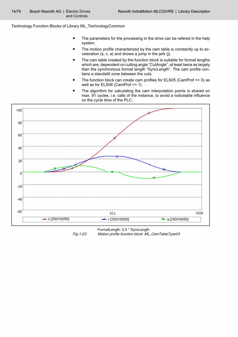
● The parameters for the processing in the drive can be refered in the helpsystem.
● The motion profile characterized by the cam table is constantly up to ac‐celeration (s, v, a) and shows a jump in the jerk (j).
● The cam table created by the function block is suitable for format lengthswhich are, dependent on cutting angle “CutAngle”, at least twice as largelythan the synchronous format length “SyncLength”. The cam profile con‐tains a standstill zone between the cuts.
● The function block can create cam profiles for ELS05 (CamProf == 0) aswell as for ELS06 (CamProf == 1).
● The algorithm for calculating the cam interpolation points is shared onmax. 91 cycles, i.e. calls of the instance, to avoid a noticeable influenceon the cycle time of the PLC.
FormatLength: 2.5 * SyncLengthFig.1-23: Motion profile function block: ML_CamTableType03
14/79 Bosch Rexroth AG | Electric Drivesand Controls
Rexroth IndraMotion MLC02VRS | Library Description
Technology Function Blocks of Library ML_TechnologyCommon
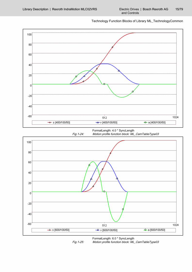
FormatLength: 4.0 * SyncLengthFig.1-24: Motion profile function block: ML_CamTableType03
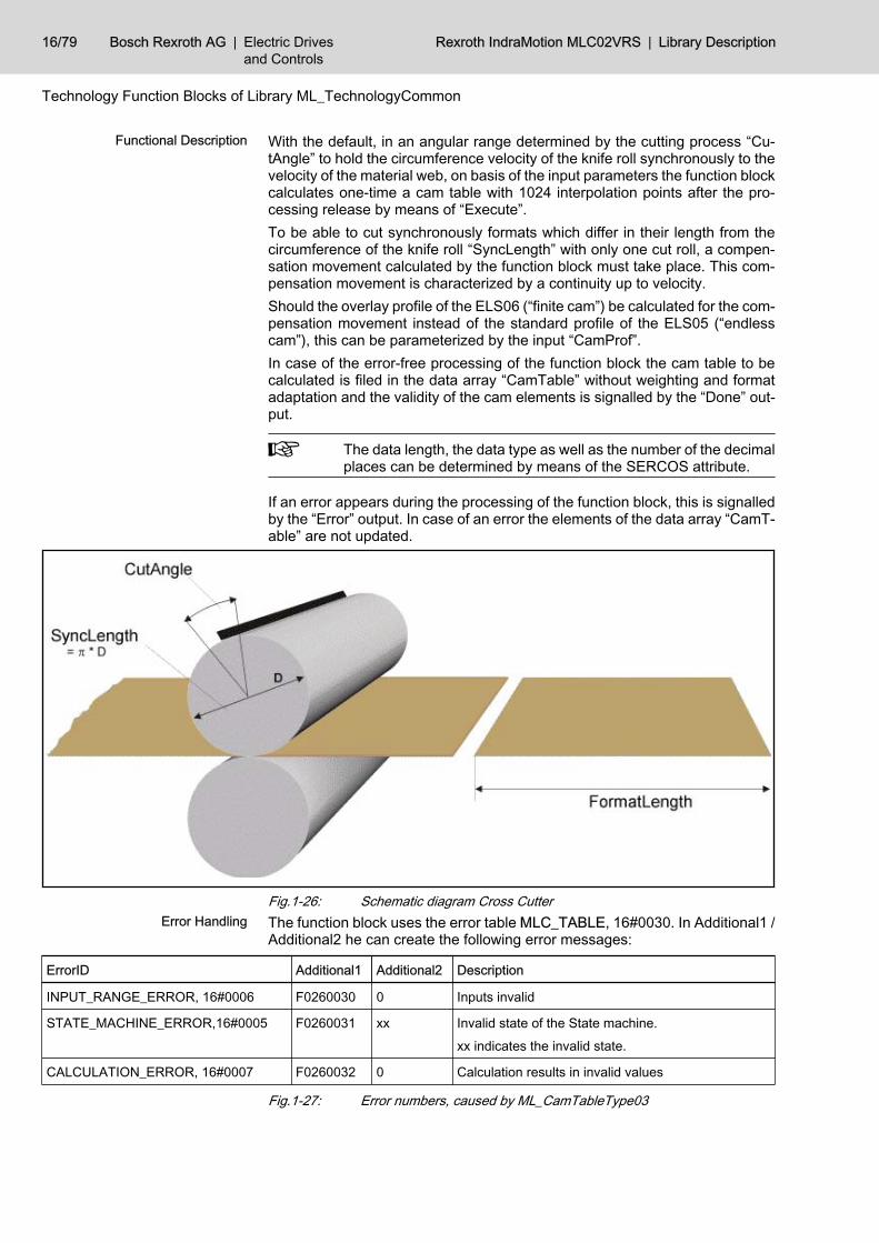
FormatLength: 6.0 * SyncLengthFig.1-25: Motion profile function block: ML_CamTableType03
Library Description | Rexroth IndraMotion MLC02VRS Electric Drivesand Controls
| Bosch Rexroth AG 15/79
Technology Function Blocks of Library ML_TechnologyCommon
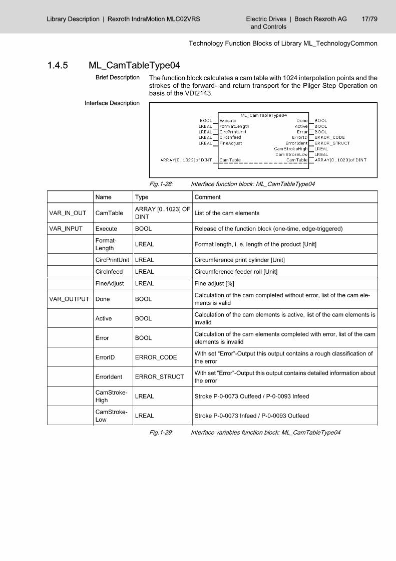
With the default, in an angular range determined by the cutting process “Cu‐tAngle” to hold the circumference velocity of the knife roll synchronously to thevelocity of the material web, on basis of the input parameters the function blockcalculates one-time a cam table with 1024 interpolation points after the pro‐cessing release by means of “Execute”.To be able to cut synchronously formats which differ in their length from thecircumference of the knife roll “SyncLength” with only one cut roll, a compen‐sation movement calculated by the function block must take place. This com‐pensation movement is characterized by a continuity up to velocity.Should the overlay profile of the ELS06 (“finite cam”) be calculated for the com‐pensation movement instead of the standard profile of the ELS05 (“endlesscam”), this can be parameterized by the input “CamProf”.In case of the error-free processing of the function block the cam table to becalculated is filed in the data array “CamTable” without weighting and formatadaptation and the validity of the cam elements is signalled by the “Done” out‐put.
The data length, the data type as well as the number of the decimalplaces can be determined by means of the SERCOS attribute.
If an error appears during the processing of the function block, this is signalledby the “Error” output. In case of an error the elements of the data array “CamT‐able” are not updated.
Fig.1-26: Schematic diagram Cross CutterThe function block uses the error table MLC_TABLE, 16#0030. In Additional1 /Additional2 he can create the following error messages:
ErrorID Additional1 Additional2 Description
INPUT_RANGE_ERROR, 16#0006 F0260030 0 Inputs invalid
STATE_MACHINE_ERROR,16#0005 F0260031 xx Invalid state of the State machine.
xx indicates the invalid state.
CALCULATION_ERROR, 16#0007 F0260032 0 Calculation results in invalid values
Fig.1-27: Error numbers, caused by ML_CamTableType03
Functional Description
Error Handling
16/79 Bosch Rexroth AG | Electric Drivesand Controls
Rexroth IndraMotion MLC02VRS | Library Description
Technology Function Blocks of Library ML_TechnologyCommon
1.4.5 ML_CamTableType04The function block calculates a cam table with 1024 interpolation points and thestrokes of the forward- and return transport for the Pilger Step Operation onbasis of the VDI2143.
Fig.1-28: Interface function block: ML_CamTableType04
Name Type Comment
VAR_IN_OUT CamTable ARRAY [0..1023] OFDINT List of the cam elements
VAR_INPUT Execute BOOL Release of the function block (one-time, edge-triggered)
Format‐Length LREAL Format length, i. e. length of the product [Unit]
CircPrintUnit LREAL Circumference print cylinder [Unit]
CircInfeed LREAL Circumference feeder roll [Unit]
FineAdjust LREAL Fine adjust [%]
VAR_OUTPUT Done BOOL Calculation of the cam completed without error, list of the cam ele‐ments is valid
Active BOOL Calculation of the cam elements is active, list of the cam elements isinvalid
Error BOOL Calculation of the cam elements completed with error, list of the camelements is invalid
ErrorID ERROR_CODE With set “Error”-Output this output contains a rough classification ofthe error
ErrorIdent ERROR_STRUCT With set “Error”-Output this output contains detailed information aboutthe error
CamStroke‐High LREAL Stroke P-0-0073 Outfeed / P-0-0093 Infeed
CamStroke‐Low LREAL Stroke P-0-0073 Infeed / P-0-0093 Outfeed
Fig.1-29: Interface variables function block: ML_CamTableType04
Brief Description
Interface Description
Library Description | Rexroth IndraMotion MLC02VRS Electric Drivesand Controls
| Bosch Rexroth AG 17/79
Technology Function Blocks of Library ML_TechnologyCommon
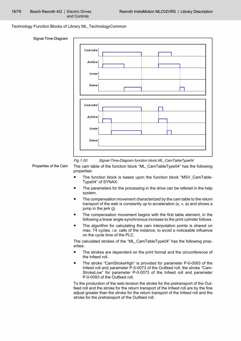
Fig.1-30: Signal-Time-Diagram function block ML_CamTableType04The cam table of the function block “ML_CamTableType04” has the followingproperties:● The function block is based upon the function block “MSV_CamTable‐
Type04” of SYNAX.● The parameters for the processing in the drive can be refered in the help
system.● The compensation movement characterized by the cam table to the return
transport of the web is constantly up to acceleration (s, v, a) and shows ajump in the jerk (j).
● The compensation movement begins with the first table element, in thefollowing a linear angle-synchronous increase to the print cylinder follows.
● The algorithm for calculating the cam interpolation points is shared onmax. 74 cycles, i.e. calls of the instance, to avoid a noticeable influenceon the cycle time of the PLC.
The calculated strokes of the “ML_CamTableType04” has the following prop‐erties:● The strokes are dependent on the print format and the circumference of
the Infeed roll.● The stroke “CamStrokeHigh” is provided for parameter P-0-0093 of the
Infeed roll and parameter P-0-0073 of the Outfeed roll, the stroke “Cam‐StrokeLow” for parameter P-0-0073 of the Infeed roll and parameterP-0-0093 of the Outfeed roll.
To the production of the web tension the stroke for the pretransport of the Out‐feed roll and the stroke for the return transport of the Infeed roll are by the fineadjust greater than the stroke for the return transport of the Infeed roll and thestroke for the pretransport of the Outfeed roll.
Signal-Time-Diagram
Properties of the Cam
18/79 Bosch Rexroth AG | Electric Drivesand Controls
Rexroth IndraMotion MLC02VRS | Library Description
Technology Function Blocks of Library ML_TechnologyCommon
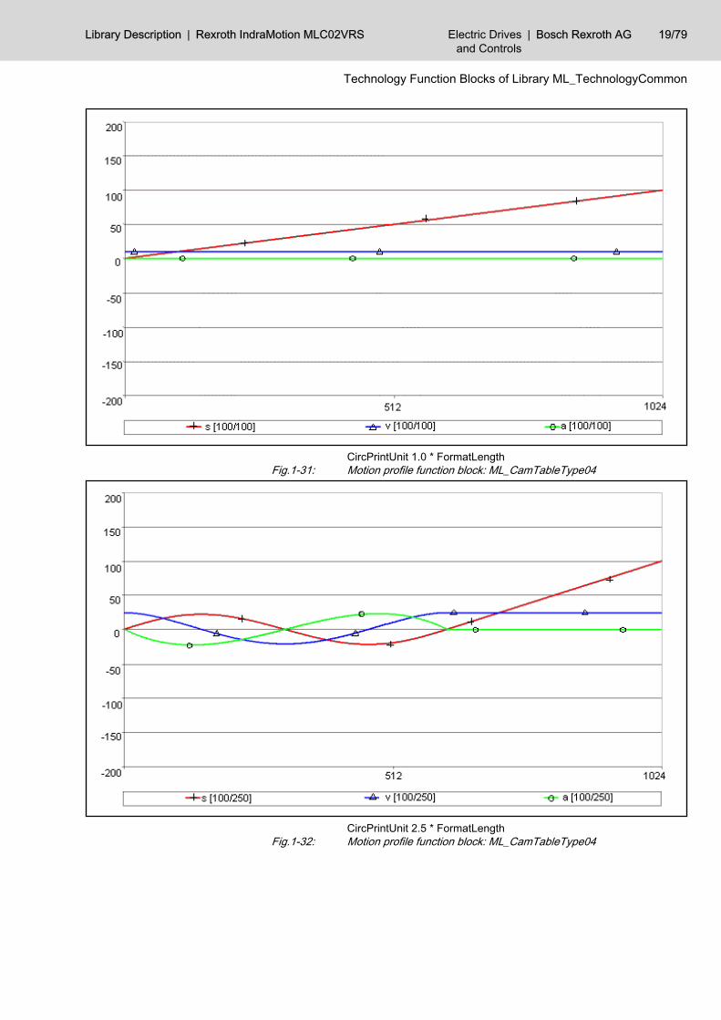
CircPrintUnit 1.0 * FormatLengthFig.1-31: Motion profile function block: ML_CamTableType04
CircPrintUnit 2.5 * FormatLengthFig.1-32: Motion profile function block: ML_CamTableType04
Library Description | Rexroth IndraMotion MLC02VRS Electric Drivesand Controls
| Bosch Rexroth AG 19/79
Technology Function Blocks of Library ML_TechnologyCommon
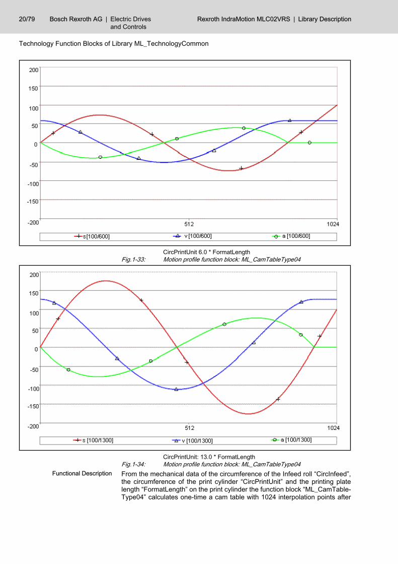
CircPrintUnit 6.0 * FormatLengthFig.1-33: Motion profile function block: ML_CamTableType04
CircPrintUnit: 13.0 * FormatLengthFig.1-34: Motion profile function block: ML_CamTableType04From the mechanical data of the circumference of the Infeed roll “CircInfeed”,the circumference of the print cylinder “CircPrintUnit” and the printing platelength “FormatLength” on the print cylinder the function block “ML_CamTable‐Type04” calculates one-time a cam table with 1024 interpolation points after
Functional Description
20/79 Bosch Rexroth AG | Electric Drivesand Controls
Rexroth IndraMotion MLC02VRS | Library Description
Technology Function Blocks of Library ML_TechnologyCommon
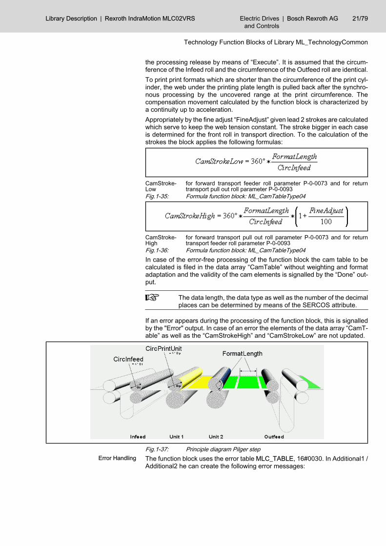
the processing release by means of “Execute”. It is assumed that the circum‐ference of the Infeed roll and the circumference of the Outfeed roll are identical.To print print formats which are shorter than the circumference of the print cyl‐inder, the web under the printing plate length is pulled back after the synchro‐nous processing by the uncovered range at the print circumference. Thecompensation movement calculated by the function block is characterized bya continuity up to acceleration.Appropriately by the fine adjust “FineAdjust” given lead 2 strokes are calculatedwhich serve to keep the web tension constant. The stroke bigger in each caseis determined for the front roll in transport direction. To the calculation of thestrokes the block applies the following formulas:
CamStroke‐Low
for forward transport feeder roll parameter P‑0‑0073 and for returntransport pull out roll parameter P‑0‑0093
Fig.1-35: Formula function block: ML_CamTableType04
CamStroke‐High
for forward transport pull out roll parameter P‑0‑0073 and for returntransport feeder roll parameter P‑0‑0093
Fig.1-36: Formula function block: ML_CamTableType04In case of the error-free processing of the function block the cam table to becalculated is filed in the data array “CamTable” without weighting and formatadaptation and the validity of the cam elements is signalled by the “Done” out‐put.
The data length, the data type as well as the number of the decimalplaces can be determined by means of the SERCOS attribute.
If an error appears during the processing of the function block, this is signalledby the "Error" output. In case of an error the elements of the data array “CamT‐able” as well as the “CamStrokeHigh” and “CamStrokeLow” are not updated.
Fig.1-37: Principle diagram Pilger stepThe function block uses the error table MLC_TABLE, 16#0030. In Additional1 /Additional2 he can create the following error messages:
Error Handling
Library Description | Rexroth IndraMotion MLC02VRS Electric Drivesand Controls
| Bosch Rexroth AG 21/79
Technology Function Blocks of Library ML_TechnologyCommon
ErrorID Additional1 Additional2 Description
INPUT_RANGE_ERROR , 16#0006 F0260030 0 Inputs invalid
STATE_MACHINE_ERROR, 16#0005 F0260031 xx Invalid state of the State machine.
xx indicates the invalid state.
CALCULATION_ERROR, 16#0007 F0260032 0 Calculation results in invalid values
Fig.1-38: Error numbers, caused by ML_CamTableType04
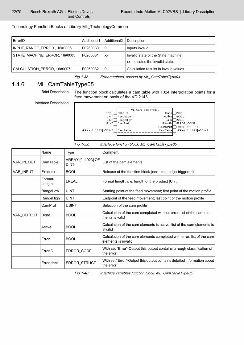
1.4.6 ML_CamTableType05The function block calculates a cam table with 1024 interpolation points for afeed movement on basis of the VDI2143.
Fig.1-39: Interface function block: ML_CamTableType05
Name Type Comment
VAR_IN_OUT CamTable ARRAY [0..1023] OFDINT List of the cam elements
VAR_INPUT Execute BOOL Release of the function block (one-time, edge-triggered)
Format‐Length LREAL Format length, i. e. length of the product [Unit]
RangeLow UINT Starting point of the feed movement; first point of the motion profile
RangeHigh UINT Endpoint of the feed movement; last point of the motion profile
CamProf USINT Selection of the cam profile
VAR_OUTPUT Done BOOL Calculation of the cam completed without error, list of the cam ele‐ments is valid
Active BOOL Calculation of the cam elements is active, list of the cam elements isinvalid
Error BOOL Calculation of the cam elements completed with error, list of the camelements is invalid
ErrorID ERROR_CODE With set “Error”-Output this output contains a rough classification ofthe error
ErrorIdent ERROR_STRUCT With set “Error”-Output this output contains detailed information aboutthe error
Fig.1-40: Interface variables function block: ML_CamTableType05
Brief Description
Interface Description
22/79 Bosch Rexroth AG | Electric Drivesand Controls
Rexroth IndraMotion MLC02VRS | Library Description
Technology Function Blocks of Library ML_TechnologyCommon
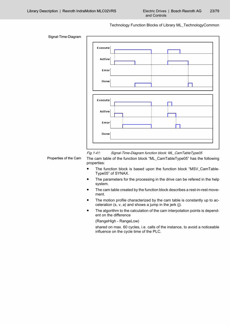
Fig.1-41: Signal-Time-Diagram function block: ML_CamTableType05The cam table of the function block “ML_CamTableType05” has the followingproperties:● The function block is based upon the function block “MSV_CamTable‐
Type05” of SYNAX.● The parameters for the processing in the drive can be refered in the help
system.● The cam table created by the function block describes a rest-in-rest move‐
ment.● The motion profile characterized by the cam table is constantly up to ac‐
celeration (s, v, a) and shows a jump in the jerk (j).● The algorithm to the calculation of the cam interpolation points is depend‐
ent on the difference(RangeHigh - RangeLow)shared on max. 60 cycles, i.e. calls of the instance, to avoid a noticeableinfluence on the cycle time of the PLC.
Signal-Time-Diagram
Properties of the Cam
Library Description | Rexroth IndraMotion MLC02VRS Electric Drivesand Controls
| Bosch Rexroth AG 23/79
Technology Function Blocks of Library ML_TechnologyCommon
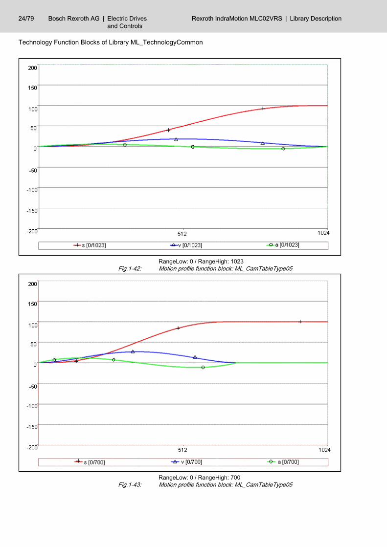
RangeLow: 0 / RangeHigh: 1023Fig.1-42: Motion profile function block: ML_CamTableType05
RangeLow: 0 / RangeHigh: 700Fig.1-43: Motion profile function block: ML_CamTableType05
24/79 Bosch Rexroth AG | Electric Drivesand Controls
Rexroth IndraMotion MLC02VRS | Library Description
Technology Function Blocks of Library ML_TechnologyCommon
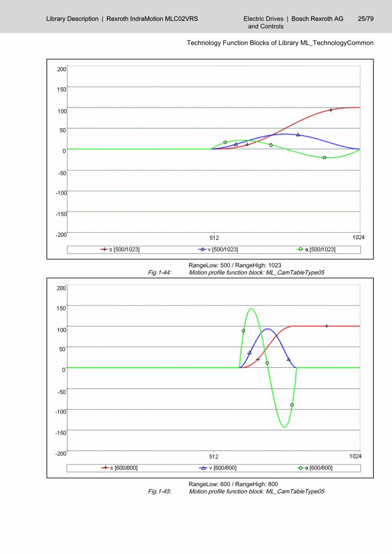
RangeLow: 500 / RangeHigh: 1023Fig.1-44: Motion profile function block: ML_CamTableType05
RangeLow: 600 / RangeHigh: 800Fig.1-45: Motion profile function block: ML_CamTableType05
Library Description | Rexroth IndraMotion MLC02VRS Electric Drivesand Controls
| Bosch Rexroth AG 25/79
Technology Function Blocks of Library ML_TechnologyCommon
With the default of a defined feed range by the limits “RangeLow” and “Ran‐geHigh” the function block “ML_CamTableType05” calculates one-time a camtable with 1024 interpolation points on the basis of the input parameters afterthe processing release by means of “Execute”.The movement of standstill in standstill takes place with a compensation move‐ment which is constantly up to acceleration.Should the overlay profile of the ELS06 (“finite cam”) be calculated for the com‐pensation movement instead of the standard profile of the ELS05 (“endlesscam”), this can be parameterized by the input “CamProf”.In case of the error-free processing of the function block the cam table to becalculated is filed in the data array “CamTable” without weighting and formatadaptation and the validity of the cam elements is signalled by the “Done” out‐put.
The data length, the data type as well as the number of the decimalplaces can be determined by means of the SERCOS attribute.
If an error appears during the processing of the function block, this is signalledby the “Error” output. In case of an error the elements of the data array “CamT‐able” are not updated.The function block uses the error table MLC_TABLE, 16#0030. In Additional1 /Additional2 he can create the following error messages:
ErrorID Additional1 Additional2 Description
INPUT_RANGE_ERROR, 16#0006 F0260030 0 Inputs invalid
STATE_MACHINE_ERROR, 16#0005 F0260031 xx Invalid state of the State machine.
xx indicates the invalid state.
Fig.1-46: Error numbers, caused by ML_CamTableType05
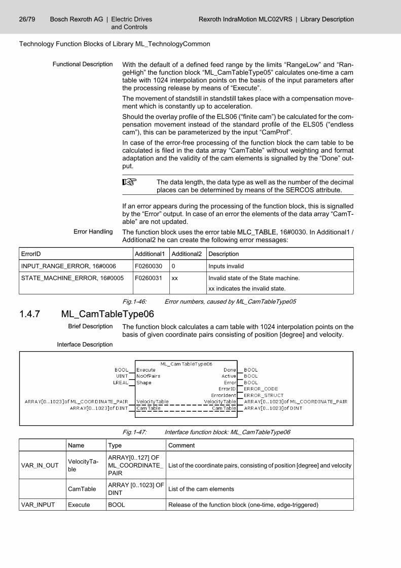
1.4.7 ML_CamTableType06The function block calculates a cam table with 1024 interpolation points on thebasis of given coordinate pairs consisting of position [degree] and velocity.
Fig.1-47: Interface function block: ML_CamTableType06
Name Type Comment
VAR_IN_OUT VelocityTa‐ble
ARRAY[0..127] OFML_COORDINATE_PAIR
List of the coordinate pairs, consisting of position [degree] and velocity
CamTable ARRAY [0..1023] OFDINT List of the cam elements
VAR_INPUT Execute BOOL Release of the function block (one-time, edge-triggered)
Functional Description
Error Handling
Brief Description
Interface Description
26/79 Bosch Rexroth AG | Electric Drivesand Controls
Rexroth IndraMotion MLC02VRS | Library Description
Technology Function Blocks of Library ML_TechnologyCommon
Name Type Comment
NoOfPairs UINT Number of valid coordinate pairs
VAR_OUTPUT Done BOOL Calculation of the cam completed without error, list of the cam ele‐ments is valid
Active BOOL Calculation of the cam elements is active, list of the cam elements isinvalid
Error BOOL Calculation of the cam elements completed with error, list of the camelements is invalid
ErrorID ERROR_CODE With set “Error”-Output this output contains a rough classification ofthe error
ErrorIdent ERROR_STRUCT With set “Error”-Output this output contains detailed information aboutthe error
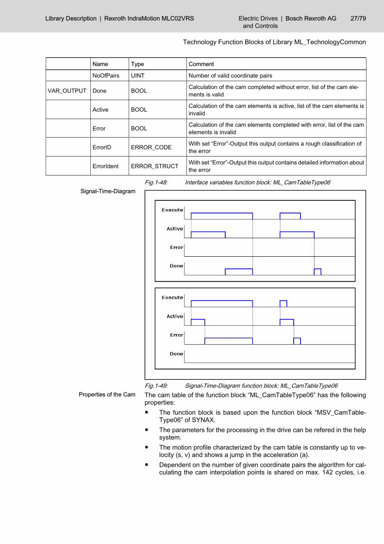
Fig.1-48: Interface variables function block: ML_CamTableType06
Fig.1-49: Signal-Time-Diagram function block: ML_CamTableType06The cam table of the function block “ML_CamTableType06” has the followingproperties:● The function block is based upon the function block “MSV_CamTable‐
Type06” of SYNAX.● The parameters for the processing in the drive can be refered in the help
system.● The motion profile characterized by the cam table is constantly up to ve‐
locity (s, v) and shows a jump in the acceleration (a).● Dependent on the number of given coordinate pairs the algorithm for cal‐
culating the cam interpolation points is shared on max. 142 cycles, i.e.
Signal-Time-Diagram
Properties of the Cam
Library Description | Rexroth IndraMotion MLC02VRS Electric Drivesand Controls
| Bosch Rexroth AG 27/79
Technology Function Blocks of Library ML_TechnologyCommon
calls of the instance, to avoid a noticeable influence on the cycle time ofthe PLC.
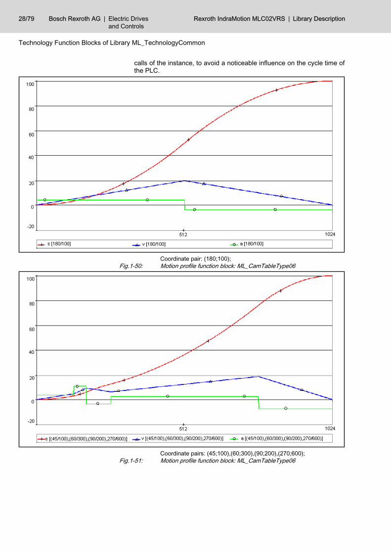
Coordinate pair: (180;100);Fig.1-50: Motion profile function block: ML_CamTableType06
Coordinate pairs: (45;100),(60;300),(90;200),(270;600);Fig.1-51: Motion profile function block: ML_CamTableType06
28/79 Bosch Rexroth AG | Electric Drivesand Controls
Rexroth IndraMotion MLC02VRS | Library Description
Technology Function Blocks of Library ML_TechnologyCommon
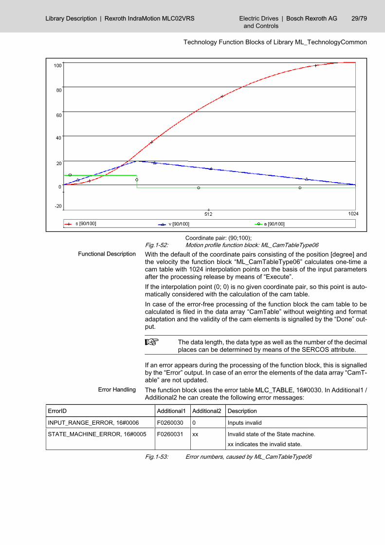
Coordinate pair: (90;100);Fig.1-52: Motion profile function block: ML_CamTableType06With the default of the coordinate pairs consisting of the position [degree] andthe velocity the function block “ML_CamTableType06” calculates one-time acam table with 1024 interpolation points on the basis of the input parametersafter the processing release by means of “Execute”.If the interpolation point (0; 0) is no given coordinate pair, so this point is auto‐matically considered with the calculation of the cam table.In case of the error-free processing of the function block the cam table to becalculated is filed in the data array “CamTable” without weighting and formatadaptation and the validity of the cam elements is signalled by the “Done” out‐put.
The data length, the data type as well as the number of the decimalplaces can be determined by means of the SERCOS attribute.
If an error appears during the processing of the function block, this is signalledby the “Error” output. In case of an error the elements of the data array “CamT‐able” are not updated.The function block uses the error table MLC_TABLE, 16#0030. In Additional1 /Additional2 he can create the following error messages:
ErrorID Additional1 Additional2 Description
INPUT_RANGE_ERROR, 16#0006 F0260030 0 Inputs invalid
STATE_MACHINE_ERROR, 16#0005 F0260031 xx Invalid state of the State machine.
xx indicates the invalid state.
Fig.1-53: Error numbers, caused by ML_CamTableType06
Functional Description
Error Handling
Library Description | Rexroth IndraMotion MLC02VRS Electric Drivesand Controls
| Bosch Rexroth AG 29/79
Technology Function Blocks of Library ML_TechnologyCommon
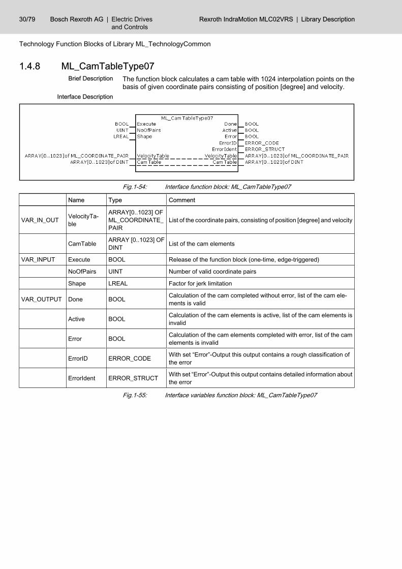
1.4.8 ML_CamTableType07The function block calculates a cam table with 1024 interpolation points on thebasis of given coordinate pairs consisting of position [degree] and velocity.
Fig.1-54: Interface function block: ML_CamTableType07
Name Type Comment
VAR_IN_OUT VelocityTa‐ble
ARRAY[0..1023] OFML_COORDINATE_PAIR
List of the coordinate pairs, consisting of position [degree] and velocity
CamTable ARRAY [0..1023] OFDINT List of the cam elements
VAR_INPUT Execute BOOL Release of the function block (one-time, edge-triggered)
NoOfPairs UINT Number of valid coordinate pairs
Shape LREAL Factor for jerk limitation
VAR_OUTPUT Done BOOL Calculation of the cam completed without error, list of the cam ele‐ments is valid
Active BOOL Calculation of the cam elements is active, list of the cam elements isinvalid
Error BOOL Calculation of the cam elements completed with error, list of the camelements is invalid
ErrorID ERROR_CODE With set “Error”-Output this output contains a rough classification ofthe error
ErrorIdent ERROR_STRUCT With set “Error”-Output this output contains detailed information aboutthe error
Fig.1-55: Interface variables function block: ML_CamTableType07
Brief Description
Interface Description
30/79 Bosch Rexroth AG | Electric Drivesand Controls
Rexroth IndraMotion MLC02VRS | Library Description
Technology Function Blocks of Library ML_TechnologyCommon
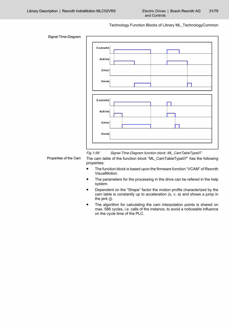
Fig.1-56: Signal-Time-Diagram function block: ML_CamTableType07The cam table of the function block “ML_CamTableType07” has the followingproperties:● The function block is based upon the firmware function “VCAM” of Rexroth
VisualMotion.● The parameters for the processing in the drive can be refered in the help
system.● Dependent on the “Shape” factor the motion profile characterized by the
cam table is constantly up to acceleration (s, v, a) and shows a jump inthe jerk (j).
● The algorithm for calculating the cam interpolation points is shared onmax. 586 cycles, i.e. calls of the instance, to avoid a noticeable influenceon the cycle time of the PLC.
Signal-Time-Diagram
Properties of the Cam
Library Description | Rexroth IndraMotion MLC02VRS Electric Drivesand Controls
| Bosch Rexroth AG 31/79
Technology Function Blocks of Library ML_TechnologyCommon
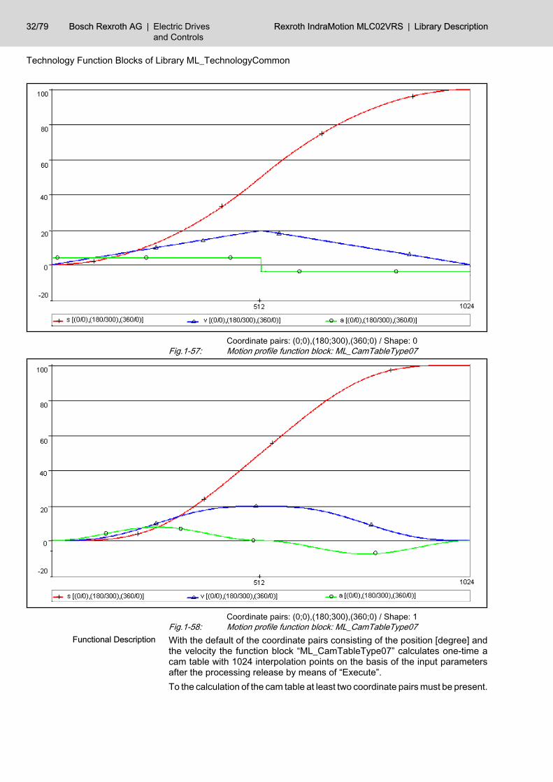
Coordinate pairs: (0;0),(180;300),(360;0) / Shape: 0Fig.1-57: Motion profile function block: ML_CamTableType07
Coordinate pairs: (0;0),(180;300),(360;0) / Shape: 1Fig.1-58: Motion profile function block: ML_CamTableType07With the default of the coordinate pairs consisting of the position [degree] andthe velocity the function block “ML_CamTableType07” calculates one-time acam table with 1024 interpolation points on the basis of the input parametersafter the processing release by means of “Execute”.To the calculation of the cam table at least two coordinate pairs must be present.
Functional Description
32/79 Bosch Rexroth AG | Electric Drivesand Controls
Rexroth IndraMotion MLC02VRS | Library Description
Technology Function Blocks of Library ML_TechnologyCommon
By the factor “Shape”, which is intended to the limitation of the jerk, smoothingthe velocity takes place. The effect of the factor is to be seen in the previousfigures.The cam calculated by the function block ML_CamTableType07 is usable onlyas an endless cam, if the first (0; 0) and the last interpolation point amount to(360; 0). If this is not the case, so with the transitions of the cams it comes todiscontinuities in the position.If the interpolation points named at the top are inserted with the function blockand the factor “Shape” is set to 0%, the created cam is identical to the cam offunction block ML_CamTableType06 , page 26,.In case of the error-free processing of the function block the cam table to becalculated is filed in the data array “CamTable” without weighting and formatadaptation and the validity of the cam elements is signalled by the “Done” out‐put.
The data length, the data type as well as the number of the decimalplaces can be determined by means of the SERCOS attribute.
If an error appears during the processing of the function block, this is signalledby the “Error” output. In case of an error the elements of the data array “CamT‐able” are not updated.The function block uses the error table MLC_TABLE, 16#0030. In Additional1 /Additional2 he can create the following error messages:
ErrorID Additional1 Additional2 Description
INPUT_RANGE_ERROR, 16#0006 F0260030 0 Inputs invalid
STATE_MACHINE_ERROR, 16#0005 F0260031 xx Invalid state of the State machine.
xx indicates the invalid state.
Fig.1-59: Error numbers, caused by ML_CamTableType07
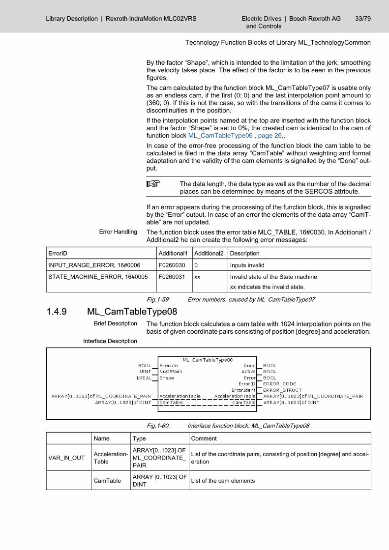
1.4.9 ML_CamTableType08The function block calculates a cam table with 1024 interpolation points on thebasis of given coordinate pairs consisting of position [degree] and acceleration.
Fig.1-60: Interface function block: ML_CamTableType08
Name Type Comment
VAR_IN_OUT Acceleration‐Table
ARRAY[0..1023] OFML_COORDINATE_PAIR
List of the coordinate pairs, consisting of position [degree] and accel‐eration
CamTable ARRAY [0..1023] OFDINT List of the cam elements
Error Handling
Brief Description
Interface Description
Library Description | Rexroth IndraMotion MLC02VRS Electric Drivesand Controls
| Bosch Rexroth AG 33/79
Technology Function Blocks of Library ML_TechnologyCommon
Name Type Comment
VAR_INPUT Execute BOOL Release of the function block (one-time, edge-triggered)
NoOfPairs UINT Number of valid coordinate pairs
Shape LREAL Factor for jerk limitation
VAR_OUTPUT Done BOOL Calculation of the cam completed without error, list of the cam ele‐ments is valid
Active BOOL Calculation of the cam elements is active, list of the cam elements isinvalid
Error BOOL Calculation of the cam elements completed with error, list of the camelements is invalid
ErrorID ERROR_CODE With set “Error”-Output this output contains a rough classification ofthe error
ErrorIdent ERROR_STRUCT With set “Error”-Output this output contains detailed information aboutthe error
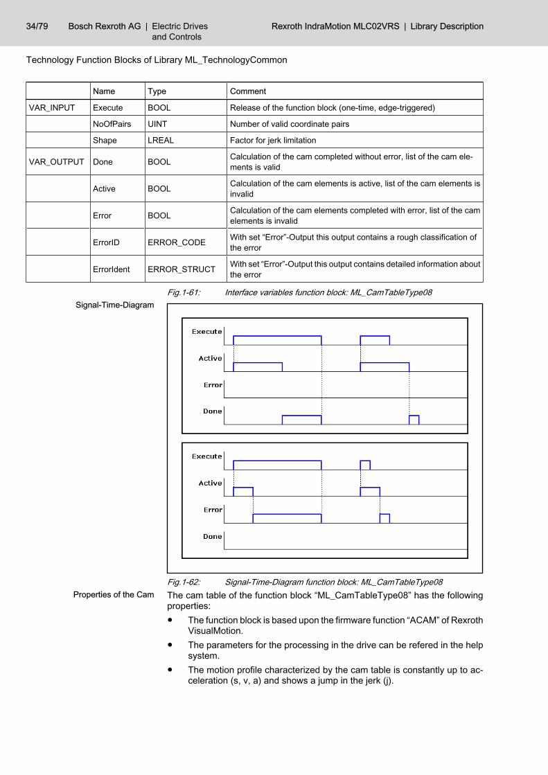
Fig.1-61: Interface variables function block: ML_CamTableType08
Fig.1-62: Signal-Time-Diagram function block: ML_CamTableType08The cam table of the function block “ML_CamTableType08” has the followingproperties:● The function block is based upon the firmware function “ACAM” of Rexroth
VisualMotion.● The parameters for the processing in the drive can be refered in the help
system.● The motion profile characterized by the cam table is constantly up to ac‐
celeration (s, v, a) and shows a jump in the jerk (j).
Signal-Time-Diagram
Properties of the Cam
34/79 Bosch Rexroth AG | Electric Drivesand Controls
Rexroth IndraMotion MLC02VRS | Library Description
Technology Function Blocks of Library ML_TechnologyCommon
● The algorithm for calculating the cam interpolation points is shared onmax. 586 cycles, i.e. calls of the instance, to avoid a noticeable influenceon the cycle time of the PLC.
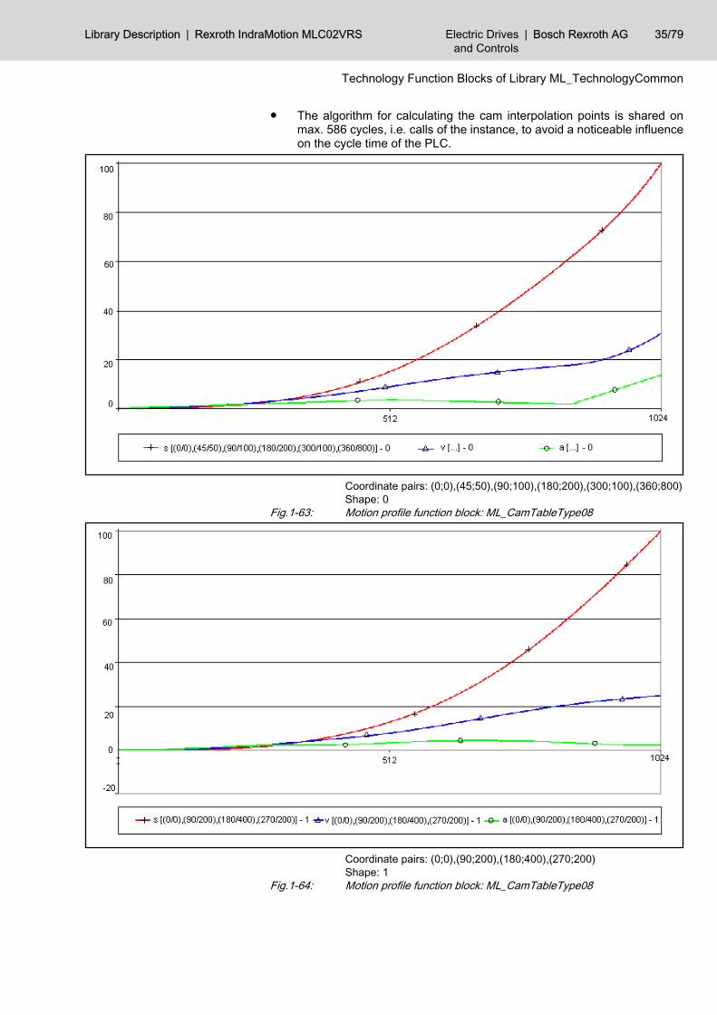
Coordinate pairs: (0;0),(45;50),(90;100),(180;200),(300;100),(360;800)Shape: 0
Fig.1-63: Motion profile function block: ML_CamTableType08
Coordinate pairs: (0;0),(90;200),(180;400),(270;200)Shape: 1
Fig.1-64: Motion profile function block: ML_CamTableType08
Library Description | Rexroth IndraMotion MLC02VRS Electric Drivesand Controls
| Bosch Rexroth AG 35/79
Technology Function Blocks of Library ML_TechnologyCommon
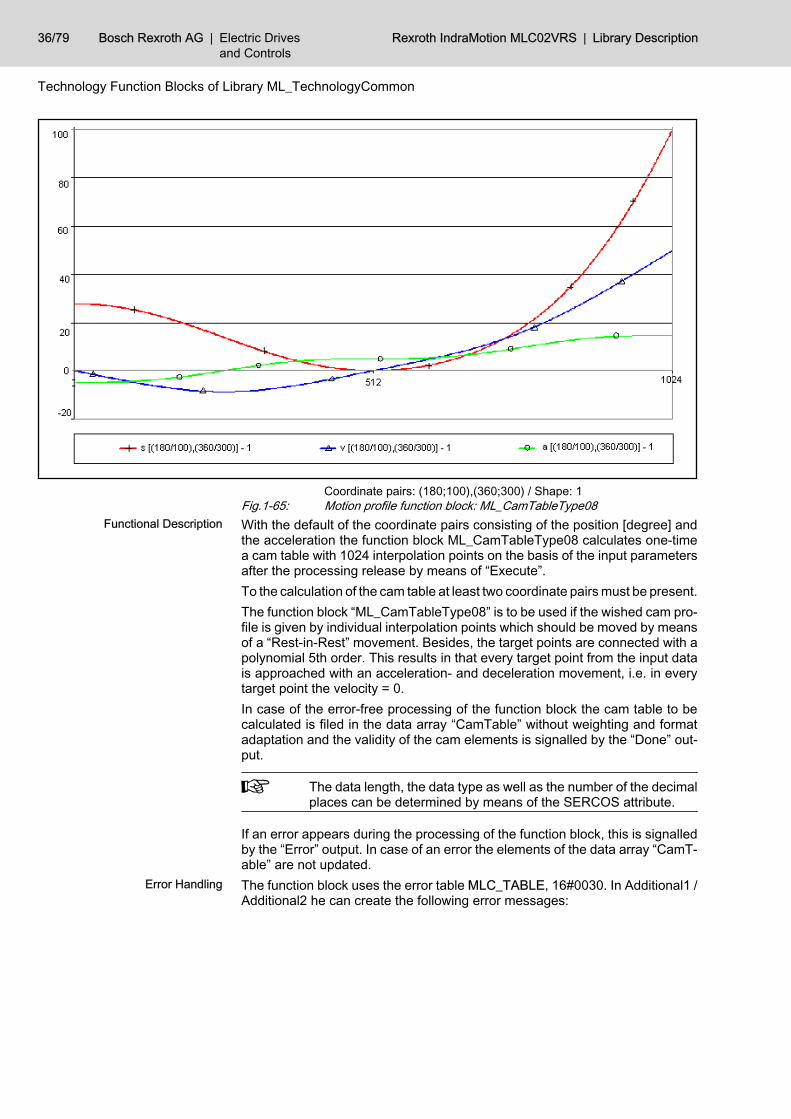
Coordinate pairs: (180;100),(360;300) / Shape: 1Fig.1-65: Motion profile function block: ML_CamTableType08With the default of the coordinate pairs consisting of the position [degree] andthe acceleration the function block ML_CamTableType08 calculates one-timea cam table with 1024 interpolation points on the basis of the input parametersafter the processing release by means of “Execute”.To the calculation of the cam table at least two coordinate pairs must be present.The function block “ML_CamTableType08” is to be used if the wished cam pro‐file is given by individual interpolation points which should be moved by meansof a “Rest-in-Rest” movement. Besides, the target points are connected with apolynomial 5th order. This results in that every target point from the input datais approached with an acceleration- and deceleration movement, i.e. in everytarget point the velocity = 0.In case of the error-free processing of the function block the cam table to becalculated is filed in the data array “CamTable” without weighting and formatadaptation and the validity of the cam elements is signalled by the “Done” out‐put.
The data length, the data type as well as the number of the decimalplaces can be determined by means of the SERCOS attribute.
If an error appears during the processing of the function block, this is signalledby the “Error” output. In case of an error the elements of the data array “CamT‐able” are not updated.The function block uses the error table MLC_TABLE, 16#0030. In Additional1 /Additional2 he can create the following error messages:
Functional Description
Error Handling
36/79 Bosch Rexroth AG | Electric Drivesand Controls
Rexroth IndraMotion MLC02VRS | Library Description
Technology Function Blocks of Library ML_TechnologyCommon
ErrorID Additional1 Additional2 Description
INPUT_RANGE_ERROR, 16#0006 F0260030 0 Inputs invalid
STATE_MACHINE_ERROR, 16#0005 F0260031 xx Invalid state of the State machine.
xx indicates the invalid state.
Fig.1-66: Error numbers, caused by ML_CamTableType08
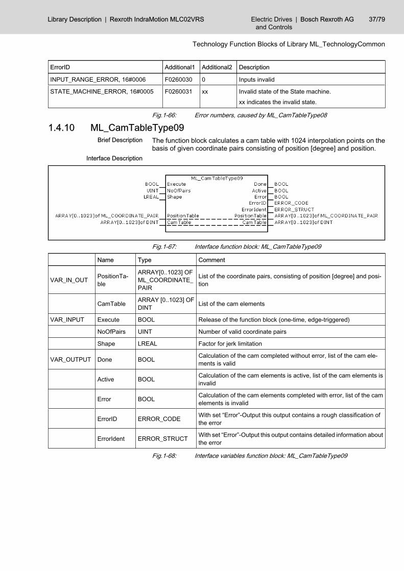
1.4.10 ML_CamTableType09The function block calculates a cam table with 1024 interpolation points on thebasis of given coordinate pairs consisting of position [degree] and position.
Fig.1-67: Interface function block: ML_CamTableType09
Name Type Comment
VAR_IN_OUT PositionTa‐ble
ARRAY[0..1023] OFML_COORDINATE_PAIR
List of the coordinate pairs, consisting of position [degree] and posi‐tion
CamTable ARRAY [0..1023] OFDINT List of the cam elements
VAR_INPUT Execute BOOL Release of the function block (one-time, edge-triggered)
NoOfPairs UINT Number of valid coordinate pairs
Shape LREAL Factor for jerk limitation
VAR_OUTPUT Done BOOL Calculation of the cam completed without error, list of the cam ele‐ments is valid
Active BOOL Calculation of the cam elements is active, list of the cam elements isinvalid
Error BOOL Calculation of the cam elements completed with error, list of the camelements is invalid
ErrorID ERROR_CODE With set “Error”-Output this output contains a rough classification ofthe error
ErrorIdent ERROR_STRUCT With set “Error”-Output this output contains detailed information aboutthe error
Fig.1-68: Interface variables function block: ML_CamTableType09
Brief Description
Interface Description
Library Description | Rexroth IndraMotion MLC02VRS Electric Drivesand Controls
| Bosch Rexroth AG 37/79
Technology Function Blocks of Library ML_TechnologyCommon
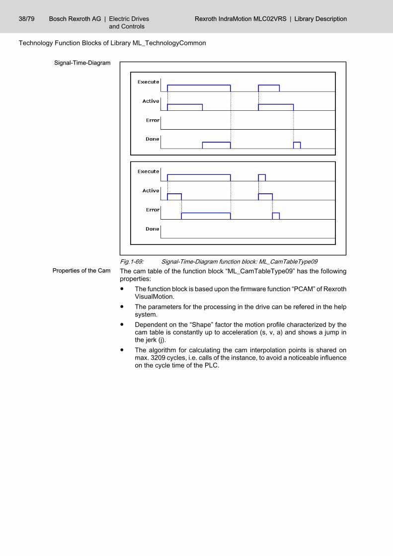
Fig.1-69: Signal-Time-Diagram function block: ML_CamTableType09The cam table of the function block “ML_CamTableType09” has the followingproperties:● The function block is based upon the firmware function “PCAM” of Rexroth
VisualMotion.● The parameters for the processing in the drive can be refered in the help
system.● Dependent on the “Shape” factor the motion profile characterized by the
cam table is constantly up to acceleration (s, v, a) and shows a jump inthe jerk (j).
● The algorithm for calculating the cam interpolation points is shared onmax. 3209 cycles, i.e. calls of the instance, to avoid a noticeable influenceon the cycle time of the PLC.
Signal-Time-Diagram
Properties of the Cam
38/79 Bosch Rexroth AG | Electric Drivesand Controls
Rexroth IndraMotion MLC02VRS | Library Description
Technology Function Blocks of Library ML_TechnologyCommon
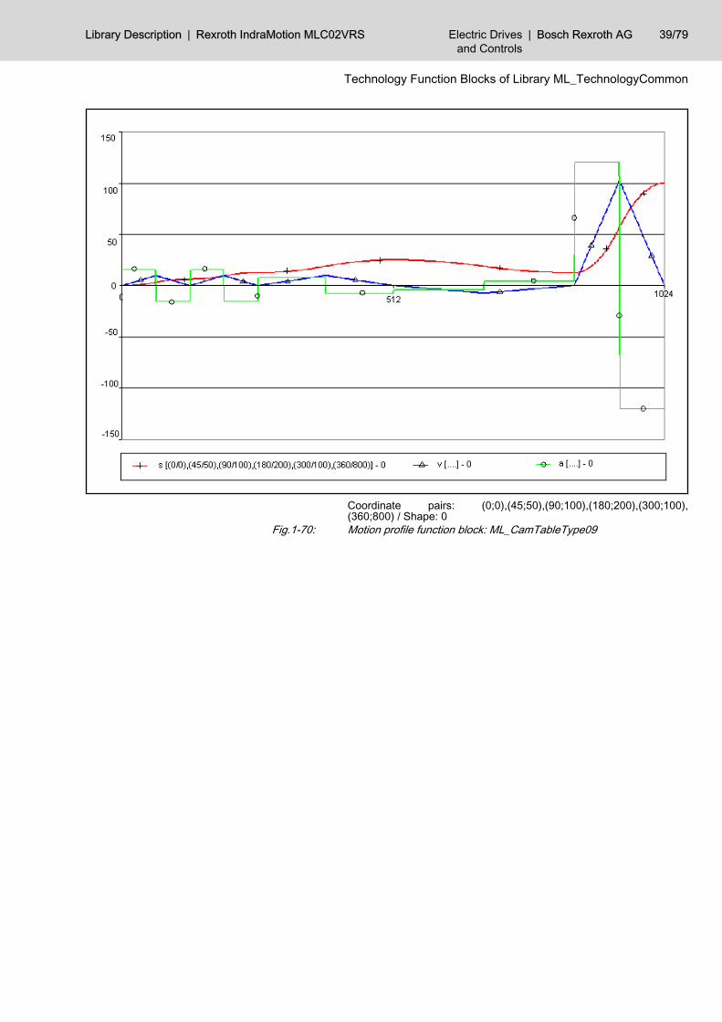
Coordinate pairs: (0;0),(45;50),(90;100),(180;200),(300;100),(360;800) / Shape: 0
Fig.1-70: Motion profile function block: ML_CamTableType09
Library Description | Rexroth IndraMotion MLC02VRS Electric Drivesand Controls
| Bosch Rexroth AG 39/79
Technology Function Blocks of Library ML_TechnologyCommon
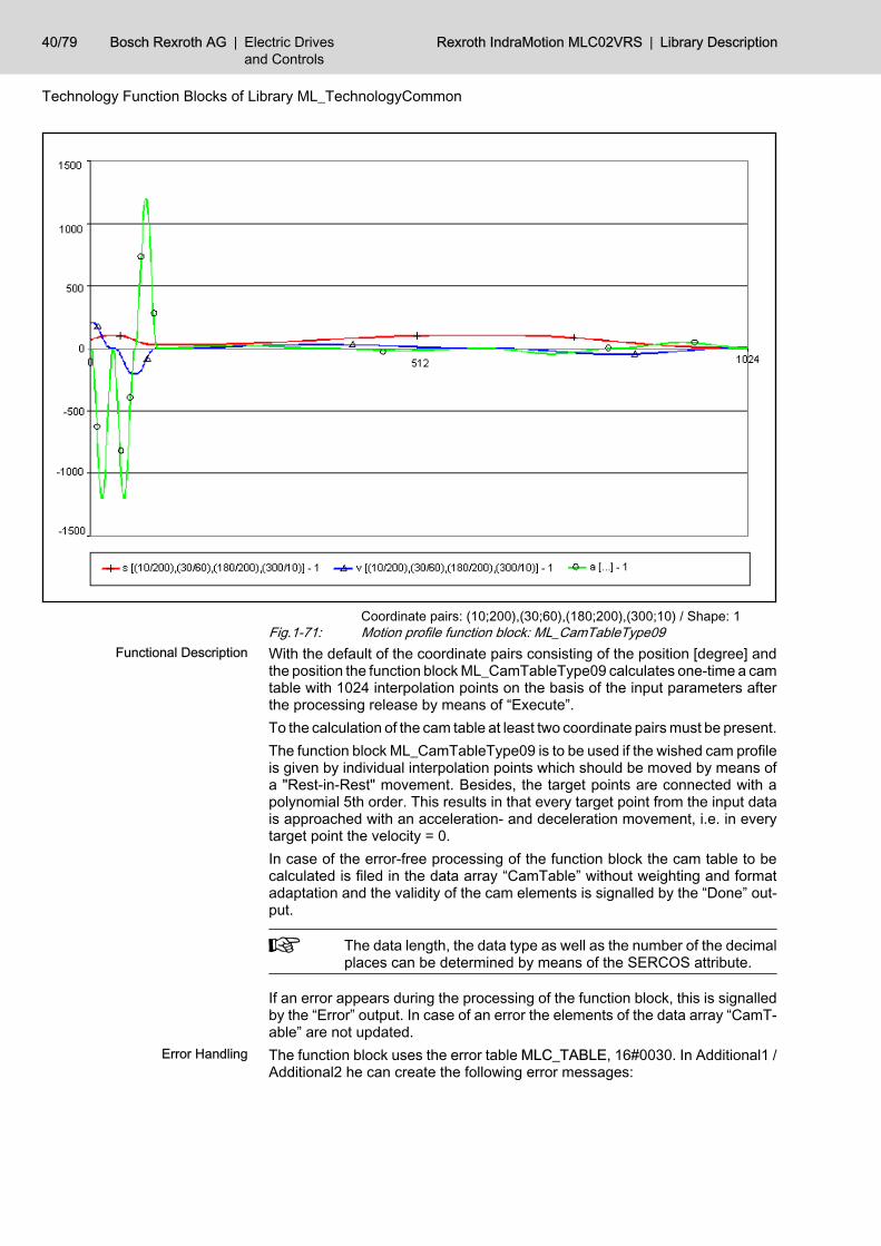
Coordinate pairs: (10;200),(30;60),(180;200),(300;10) / Shape: 1Fig.1-71: Motion profile function block: ML_CamTableType09With the default of the coordinate pairs consisting of the position [degree] andthe position the function block ML_CamTableType09 calculates one-time a camtable with 1024 interpolation points on the basis of the input parameters afterthe processing release by means of “Execute”.To the calculation of the cam table at least two coordinate pairs must be present.The function block ML_CamTableType09 is to be used if the wished cam profileis given by individual interpolation points which should be moved by means ofa "Rest-in-Rest" movement. Besides, the target points are connected with apolynomial 5th order. This results in that every target point from the input datais approached with an acceleration- and deceleration movement, i.e. in everytarget point the velocity = 0.In case of the error-free processing of the function block the cam table to becalculated is filed in the data array “CamTable” without weighting and formatadaptation and the validity of the cam elements is signalled by the “Done” out‐put.
The data length, the data type as well as the number of the decimalplaces can be determined by means of the SERCOS attribute.
If an error appears during the processing of the function block, this is signalledby the “Error” output. In case of an error the elements of the data array “CamT‐able” are not updated.The function block uses the error table MLC_TABLE, 16#0030. In Additional1 /Additional2 he can create the following error messages:
Functional Description
Error Handling
40/79 Bosch Rexroth AG | Electric Drivesand Controls
Rexroth IndraMotion MLC02VRS | Library Description
Technology Function Blocks of Library ML_TechnologyCommon
ErrorID Additional1 Additional2 Description
INPUT_RANGE_ERROR, 16#0006 F0260030 0 Inputs invalid
STATE_MACHINE_ERROR, 16#0005 F0260031 xx Invalid state of the State machine.
xx indicates the invalid state.
Fig.1-72: Error numbers, caused by ML_CamTableType09
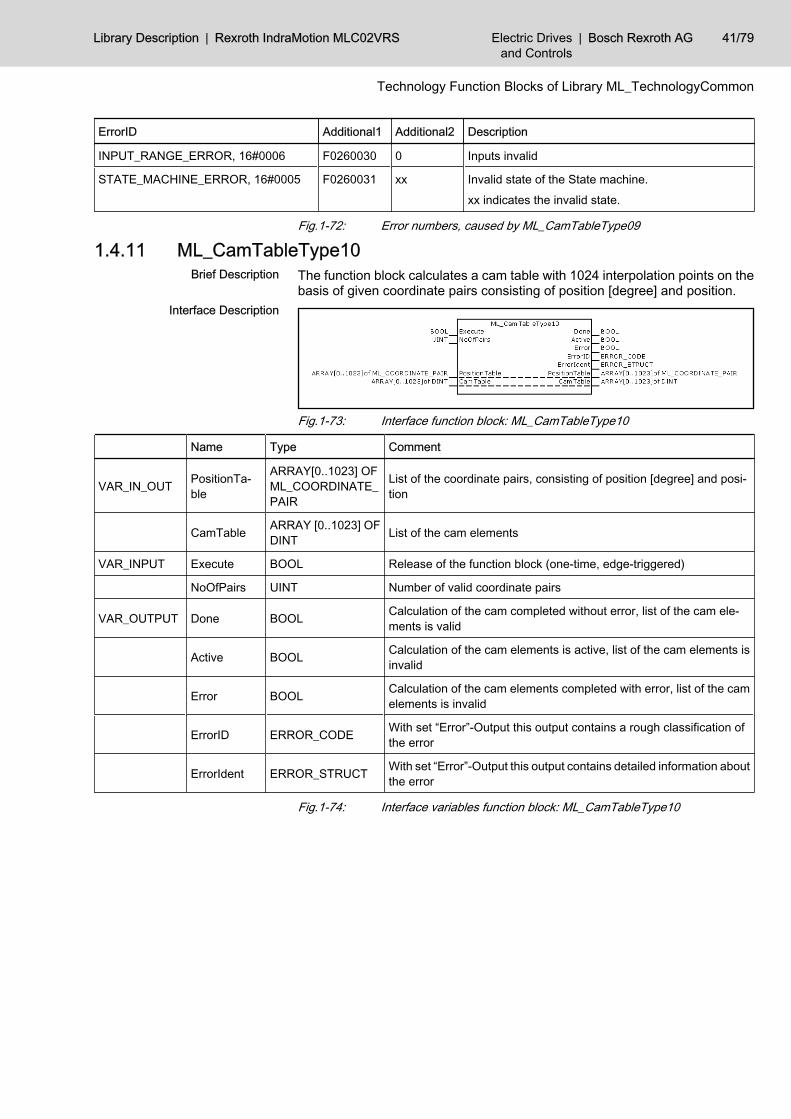
1.4.11 ML_CamTableType10The function block calculates a cam table with 1024 interpolation points on thebasis of given coordinate pairs consisting of position [degree] and position.
Fig.1-73: Interface function block: ML_CamTableType10
Name Type Comment
VAR_IN_OUT PositionTa‐ble
ARRAY[0..1023] OFML_COORDINATE_PAIR
List of the coordinate pairs, consisting of position [degree] and posi‐tion
CamTable ARRAY [0..1023] OFDINT List of the cam elements
VAR_INPUT Execute BOOL Release of the function block (one-time, edge-triggered)
NoOfPairs UINT Number of valid coordinate pairs
VAR_OUTPUT Done BOOL Calculation of the cam completed without error, list of the cam ele‐ments is valid
Active BOOL Calculation of the cam elements is active, list of the cam elements isinvalid
Error BOOL Calculation of the cam elements completed with error, list of the camelements is invalid
ErrorID ERROR_CODE With set “Error”-Output this output contains a rough classification ofthe error
ErrorIdent ERROR_STRUCT With set “Error”-Output this output contains detailed information aboutthe error
Fig.1-74: Interface variables function block: ML_CamTableType10
Brief Description
Interface Description
Library Description | Rexroth IndraMotion MLC02VRS Electric Drivesand Controls
| Bosch Rexroth AG 41/79
Technology Function Blocks of Library ML_TechnologyCommon
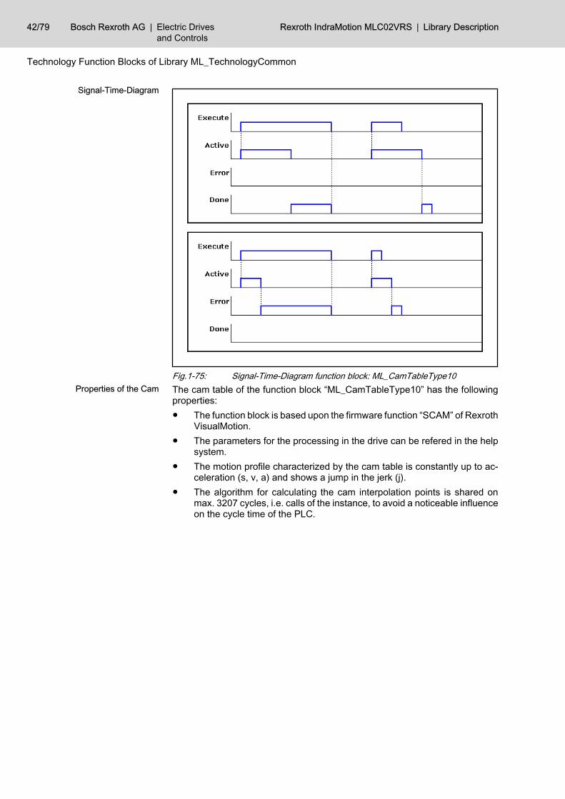
Fig.1-75: Signal-Time-Diagram function block: ML_CamTableType10The cam table of the function block “ML_CamTableType10” has the followingproperties:● The function block is based upon the firmware function “SCAM” of Rexroth
VisualMotion.● The parameters for the processing in the drive can be refered in the help
system.● The motion profile characterized by the cam table is constantly up to ac‐
celeration (s, v, a) and shows a jump in the jerk (j).● The algorithm for calculating the cam interpolation points is shared on
max. 3207 cycles, i.e. calls of the instance, to avoid a noticeable influenceon the cycle time of the PLC.
Signal-Time-Diagram
Properties of the Cam
42/79 Bosch Rexroth AG | Electric Drivesand Controls
Rexroth IndraMotion MLC02VRS | Library Description
Technology Function Blocks of Library ML_TechnologyCommon
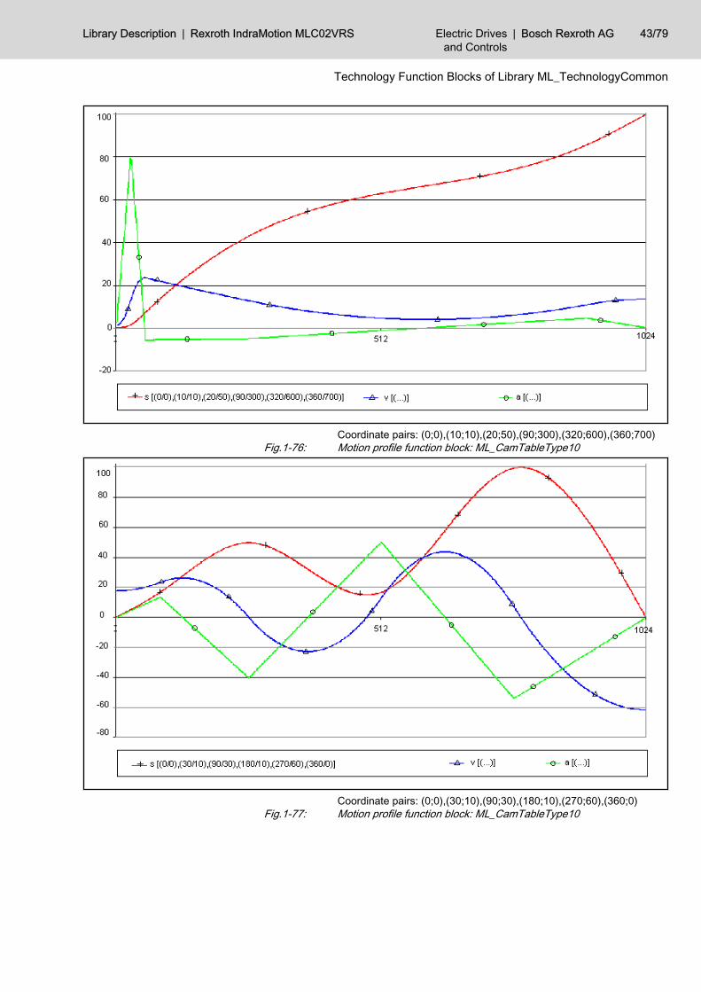
Coordinate pairs: (0;0),(10;10),(20;50),(90;300),(320;600),(360;700)Fig.1-76: Motion profile function block: ML_CamTableType10
Coordinate pairs: (0;0),(30;10),(90;30),(180;10),(270;60),(360;0)Fig.1-77: Motion profile function block: ML_CamTableType10
Library Description | Rexroth IndraMotion MLC02VRS Electric Drivesand Controls
| Bosch Rexroth AG 43/79
Technology Function Blocks of Library ML_TechnologyCommon
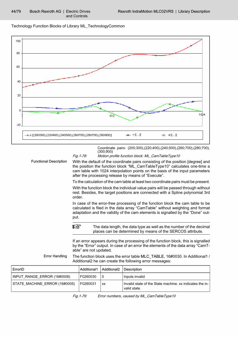
Coordinate pairs: (200;300),(220;400),(240;500),(260;700),(280;700),(300;900)
Fig.1-78: Motion profile function block: ML_CamTableType10With the default of the coordinate pairs consisting of the position [degree] andthe position the function block “ML_CamTableType10” calculates one-time acam table with 1024 interpolation points on the basis of the input parametersafter the processing release by means of “Execute”.To the calculation of the cam table at least two coordinate pairs must be present.With the function block the individual value pairs will be passed through withoutrest. Besides, the target positions are connected with a Spline polynomial 3rdorder.In case of the error-free processing of the function block the cam table to becalculated is filed in the data array “CamTable” without weighting and formatadaptation and the validity of the cam elements is signalled by the “Done” out‐put.
The data length, the data type as well as the number of the decimalplaces can be determined by means of the SERCOS attribute.
If an error appears during the processing of the function block, this is signalledby the “Error” output. In case of an error the elements of the data array “CamT‐able” are not updated.The function block uses the error table MLC_TABLE, 16#0030. In Additional1 /Additional2 he can create the following error messages:
ErrorID Additional1 Additional2 Description
INPUT_RANGE_ERROR (16#0006) F0260030 0 Inputs invalid
STATE_MACHINE_ERROR (16#0005) F0260031 xx Invalid state of the State machine. xx indicates the in‐valid state.
Fig.1-79: Error numbers, caused by ML_CamTableType10
Functional Description
Error Handling
44/79 Bosch Rexroth AG | Electric Drivesand Controls
Rexroth IndraMotion MLC02VRS | Library Description
Technology Function Blocks of Library ML_TechnologyCommon
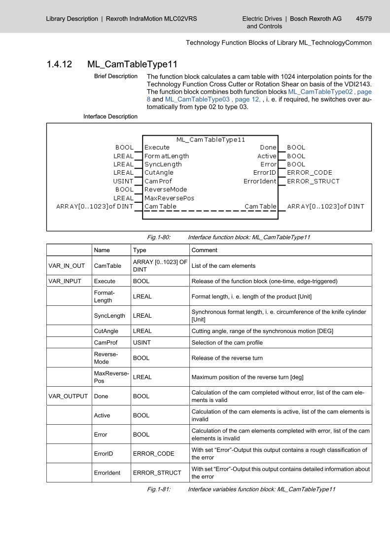
1.4.12 ML_CamTableType11The function block calculates a cam table with 1024 interpolation points for theTechnology Function Cross Cutter or Rotation Shear on basis of the VDI2143.The function block combines both function blocks ML_CamTableType02 , page8 and ML_CamTableType03 , page 12, , i. e. if required, he switches over au‐tomatically from type 02 to type 03.
Fig.1-80: Interface function block: ML_CamTableType11
Name Type Comment
VAR_IN_OUT CamTable ARRAY [0..1023] OFDINT List of the cam elements
VAR_INPUT Execute BOOL Release of the function block (one-time, edge-triggered)
Format‐Length LREAL Format length, i. e. length of the product [Unit]
SyncLength LREAL Synchronous format length, i. e. circumference of the knife cylinder[Unit]
CutAngle LREAL Cutting angle, range of the synchronous motion [DEG]
CamProf USINT Selection of the cam profile
Reverse‐Mode BOOL Release of the reverse turn
MaxReverse‐Pos LREAL Maximum position of the reverse turn [deg]
VAR_OUTPUT Done BOOL Calculation of the cam completed without error, list of the cam ele‐ments is valid
Active BOOL Calculation of the cam elements is active, list of the cam elements isinvalid
Error BOOL Calculation of the cam elements completed with error, list of the camelements is invalid
ErrorID ERROR_CODE With set “Error”-Output this output contains a rough classification ofthe error
ErrorIdent ERROR_STRUCT With set “Error”-Output this output contains detailed information aboutthe error
Fig.1-81: Interface variables function block: ML_CamTableType11
Brief Description
Interface Description
Library Description | Rexroth IndraMotion MLC02VRS Electric Drivesand Controls
| Bosch Rexroth AG 45/79
Technology Function Blocks of Library ML_TechnologyCommon
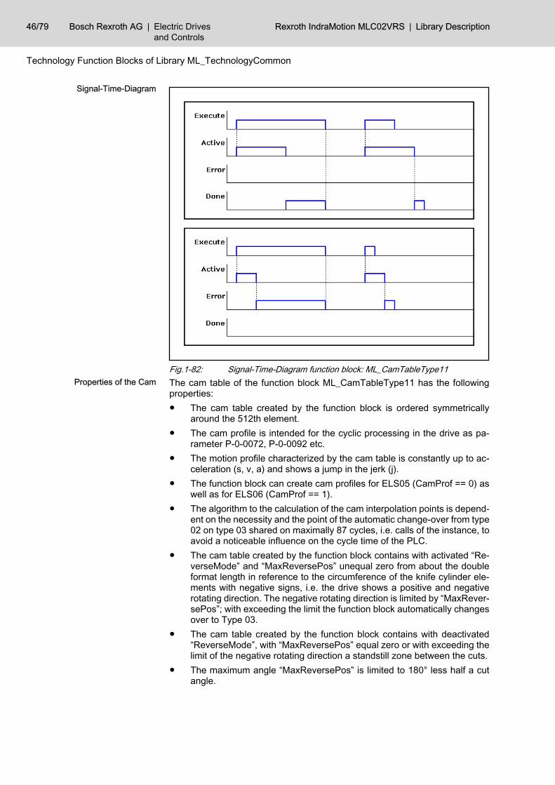
Fig.1-82: Signal-Time-Diagram function block: ML_CamTableType11The cam table of the function block ML_CamTableType11 has the followingproperties:● The cam table created by the function block is ordered symmetrically
around the 512th element.● The cam profile is intended for the cyclic processing in the drive as pa‐
rameter P-0-0072, P-0-0092 etc.● The motion profile characterized by the cam table is constantly up to ac‐
celeration (s, v, a) and shows a jump in the jerk (j).● The function block can create cam profiles for ELS05 (CamProf == 0) as
well as for ELS06 (CamProf == 1).● The algorithm to the calculation of the cam interpolation points is depend‐
ent on the necessity and the point of the automatic change-over from type02 on type 03 shared on maximally 87 cycles, i.e. calls of the instance, toavoid a noticeable influence on the cycle time of the PLC.
● The cam table created by the function block contains with activated “Re‐verseMode” and “MaxReversePos” unequal zero from about the doubleformat length in reference to the circumference of the knife cylinder ele‐ments with negative signs, i.e. the drive shows a positive and negativerotating direction. The negative rotating direction is limited by “MaxRever‐sePos”; with exceeding the limit the function block automatically changesover to Type 03.
● The cam table created by the function block contains with deactivated“ReverseMode”, with “MaxReversePos” equal zero or with exceeding thelimit of the negative rotating direction a standstill zone between the cuts.
● The maximum angle “MaxReversePos” is limited to 180° less half a cutangle.
Signal-Time-Diagram
Properties of the Cam
46/79 Bosch Rexroth AG | Electric Drivesand Controls
Rexroth IndraMotion MLC02VRS | Library Description
Technology Function Blocks of Library ML_TechnologyCommon
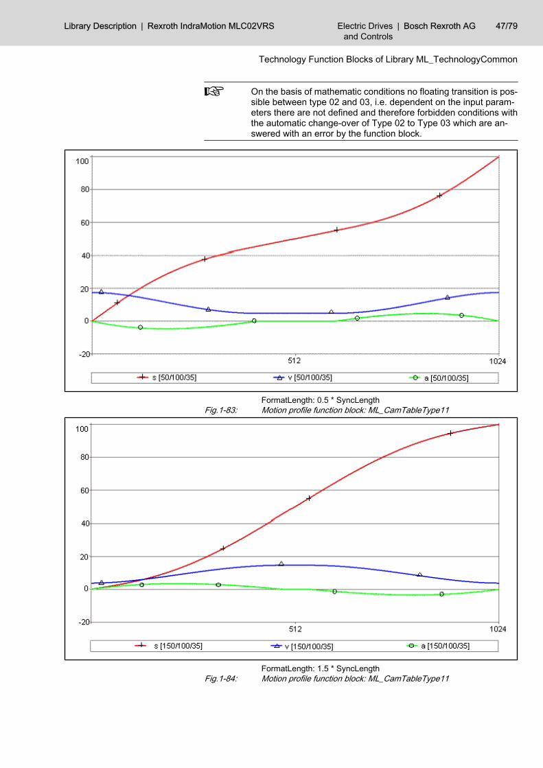
On the basis of mathematic conditions no floating transition is pos‐sible between type 02 and 03, i.e. dependent on the input param‐eters there are not defined and therefore forbidden conditions withthe automatic change-over of Type 02 to Type 03 which are an‐swered with an error by the function block.
FormatLength: 0.5 * SyncLengthFig.1-83: Motion profile function block: ML_CamTableType11
FormatLength: 1.5 * SyncLengthFig.1-84: Motion profile function block: ML_CamTableType11
Library Description | Rexroth IndraMotion MLC02VRS Electric Drivesand Controls
| Bosch Rexroth AG 47/79
Technology Function Blocks of Library ML_TechnologyCommon
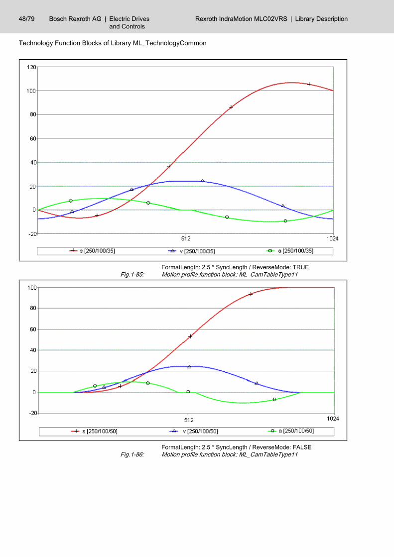
FormatLength: 2.5 * SyncLength / ReverseMode: TRUEFig.1-85: Motion profile function block: ML_CamTableType11
FormatLength: 2.5 * SyncLength / ReverseMode: FALSEFig.1-86: Motion profile function block: ML_CamTableType11
48/79 Bosch Rexroth AG | Electric Drivesand Controls
Rexroth IndraMotion MLC02VRS | Library Description
Technology Function Blocks of Library ML_TechnologyCommon
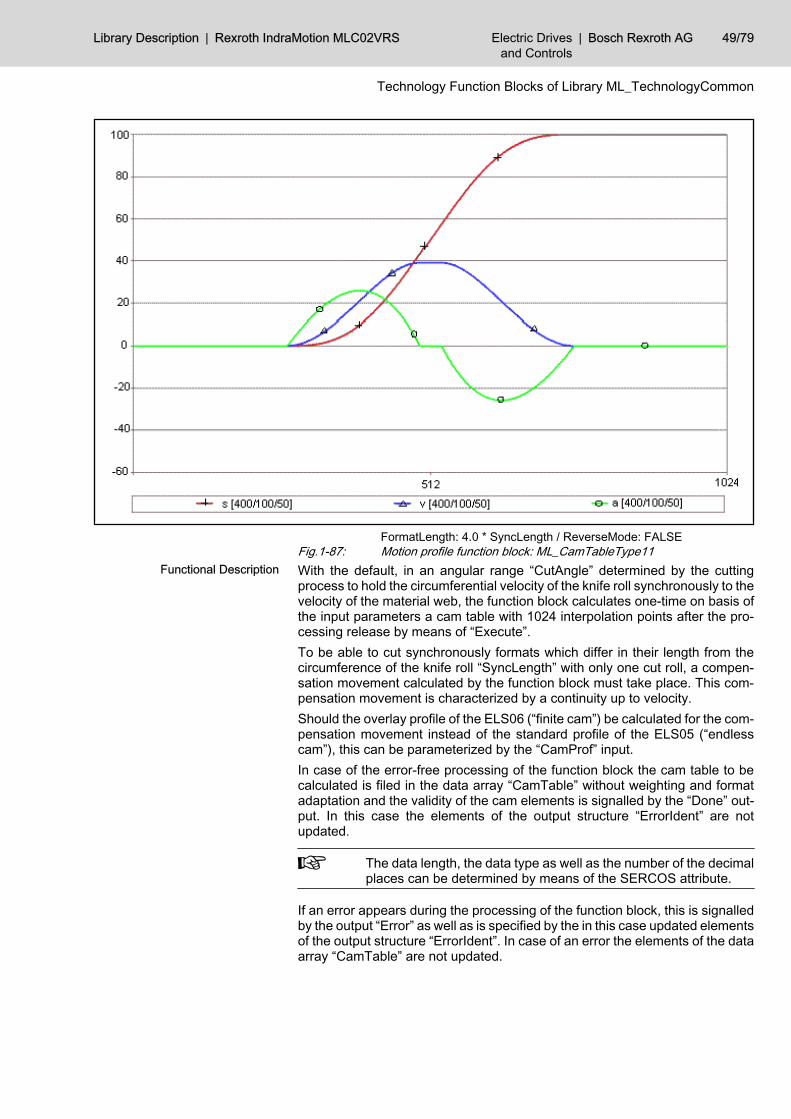
FormatLength: 4.0 * SyncLength / ReverseMode: FALSEFig.1-87: Motion profile function block: ML_CamTableType11With the default, in an angular range “CutAngle” determined by the cuttingprocess to hold the circumferential velocity of the knife roll synchronously to thevelocity of the material web, the function block calculates one-time on basis ofthe input parameters a cam table with 1024 interpolation points after the pro‐cessing release by means of “Execute”.To be able to cut synchronously formats which differ in their length from thecircumference of the knife roll “SyncLength” with only one cut roll, a compen‐sation movement calculated by the function block must take place. This com‐pensation movement is characterized by a continuity up to velocity.Should the overlay profile of the ELS06 (“finite cam”) be calculated for the com‐pensation movement instead of the standard profile of the ELS05 (“endlesscam”), this can be parameterized by the “CamProf” input.In case of the error-free processing of the function block the cam table to becalculated is filed in the data array “CamTable” without weighting and formatadaptation and the validity of the cam elements is signalled by the “Done” out‐put. In this case the elements of the output structure “ErrorIdent” are notupdated.
The data length, the data type as well as the number of the decimalplaces can be determined by means of the SERCOS attribute.
If an error appears during the processing of the function block, this is signalledby the output “Error” as well as is specified by the in this case updated elementsof the output structure “ErrorIdent”. In case of an error the elements of the dataarray “CamTable” are not updated.
Functional Description
Library Description | Rexroth IndraMotion MLC02VRS Electric Drivesand Controls
| Bosch Rexroth AG 49/79
Technology Function Blocks of Library ML_TechnologyCommon
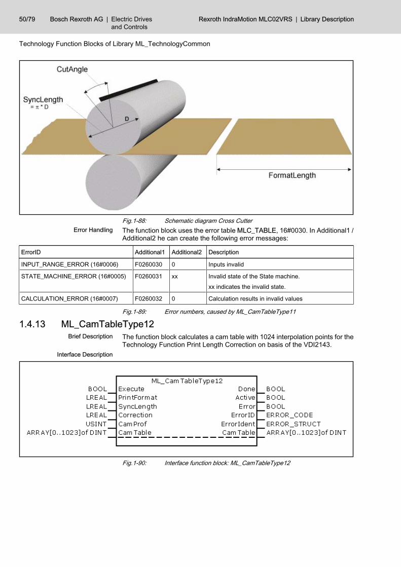
Fig.1-88: Schematic diagram Cross CutterThe function block uses the error table MLC_TABLE, 16#0030. In Additional1 /Additional2 he can create the following error messages:
ErrorID Additional1 Additional2 Description
INPUT_RANGE_ERROR (16#0006) F0260030 0 Inputs invalid
STATE_MACHINE_ERROR (16#0005) F0260031 xx Invalid state of the State machine.
xx indicates the invalid state.
CALCULATION_ERROR (16#0007) F0260032 0 Calculation results in invalid values
Fig.1-89: Error numbers, caused by ML_CamTableType11
1.4.13 ML_CamTableType12The function block calculates a cam table with 1024 interpolation points for theTechnology Function Print Length Correction on basis of the VDI2143.
Fig.1-90: Interface function block: ML_CamTableType12
Error Handling
Brief Description
Interface Description
50/79 Bosch Rexroth AG | Electric Drivesand Controls
Rexroth IndraMotion MLC02VRS | Library Description
Technology Function Blocks of Library ML_TechnologyCommon
Name Type Comment
VAR_IN_OUT CamTable ARRAY [0..1023] OFDINT List of the cam elements
VAR_INPUT Execute BOOL Release of the function block (one-time, edge-triggered)
PrintFormat LREAL Expected, nominal print format
Sync-Length LREAL Synchronous format length, i.e. circumference of the print cylinder
Correction LREAL Print correction to the compensation of the deviation
CamProf USINT Selection of the cam profile
VAR_OUTPUT Done BOOL Calculation of the cam completed without error, list of the cam ele‐ments is valid
Active BOOL Calculation of the cam elements active, output variables invalid
Error BOOL Calculation of the cam elements completed with error, output variable“ErrorIdent” is valid
ErrorID ERROR_CODE With set “Error”-Output this output contains a rough classification ofthe error
ErrorIdent ERROR_STRUCT With set “Error”-Output this output contains detailed information aboutthe error
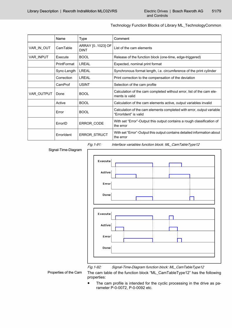
Fig.1-91: Interface variables function block: ML_CamTableType12
Fig.1-92: Signal-Time-Diagram function block: ML_CamTableType12The cam table of the function block “ML_CamTableType12” has the followingproperties:● The cam profile is intended for the cyclic processing in the drive as pa‐
rameter P-0-0072, P-0-0092 etc.
Signal-Time-Diagram
Properties of the Cam
Library Description | Rexroth IndraMotion MLC02VRS Electric Drivesand Controls
| Bosch Rexroth AG 51/79
Technology Function Blocks of Library ML_TechnologyCommon
● The motion profile characterized by the cam table is constantly up to ac‐celeration (s, v, a) and shows a jump in the jerk (j).
● The function block can create cam profiles for ELS05 (CamProf == 0) aswell as for ELS06 (CamProf == 1).
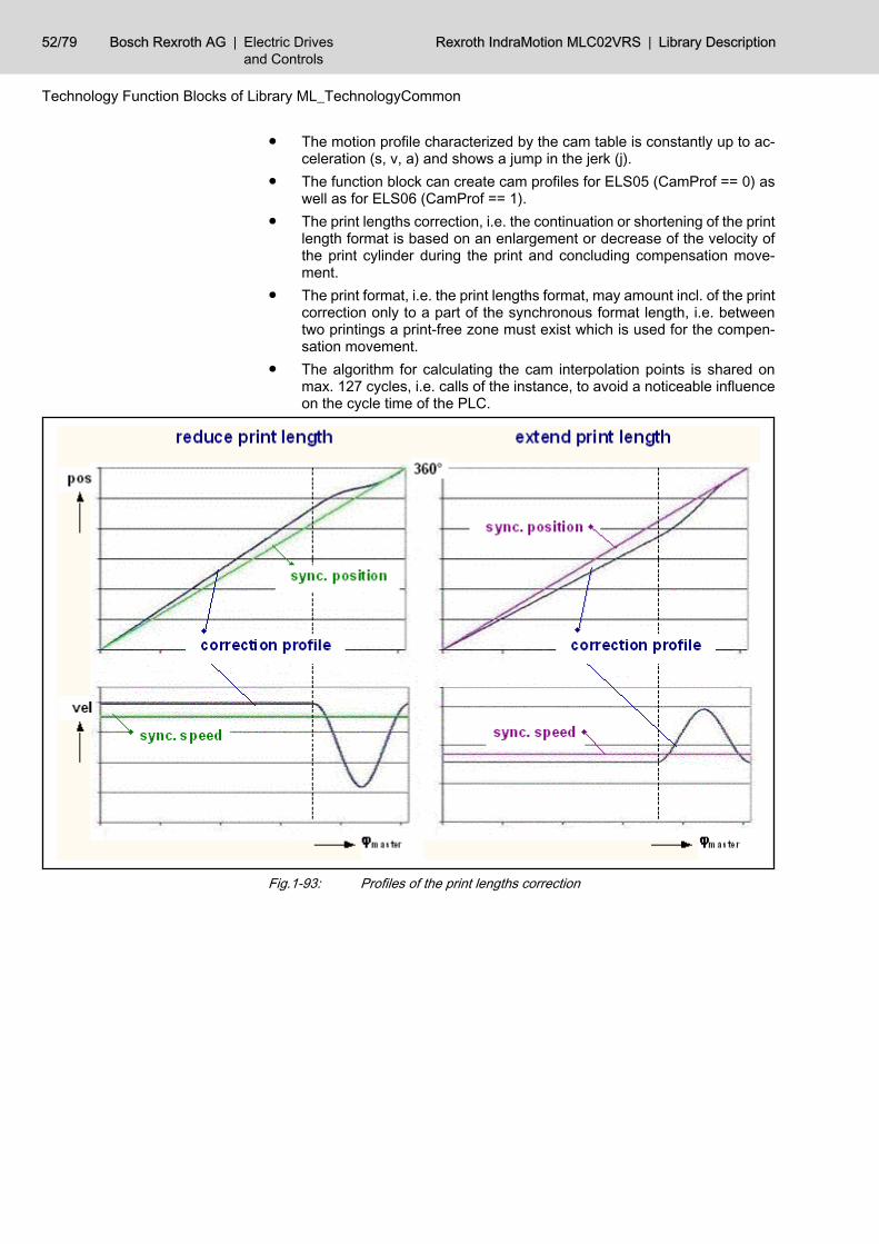
● The print lengths correction, i.e. the continuation or shortening of the printlength format is based on an enlargement or decrease of the velocity ofthe print cylinder during the print and concluding compensation move‐ment.
● The print format, i.e. the print lengths format, may amount incl. of the printcorrection only to a part of the synchronous format length, i.e. betweentwo printings a print-free zone must exist which is used for the compen‐sation movement.
● The algorithm for calculating the cam interpolation points is shared onmax. 127 cycles, i.e. calls of the instance, to avoid a noticeable influenceon the cycle time of the PLC.
Fig.1-93: Profiles of the print lengths correction
52/79 Bosch Rexroth AG | Electric Drivesand Controls
Rexroth IndraMotion MLC02VRS | Library Description
Technology Function Blocks of Library ML_TechnologyCommon
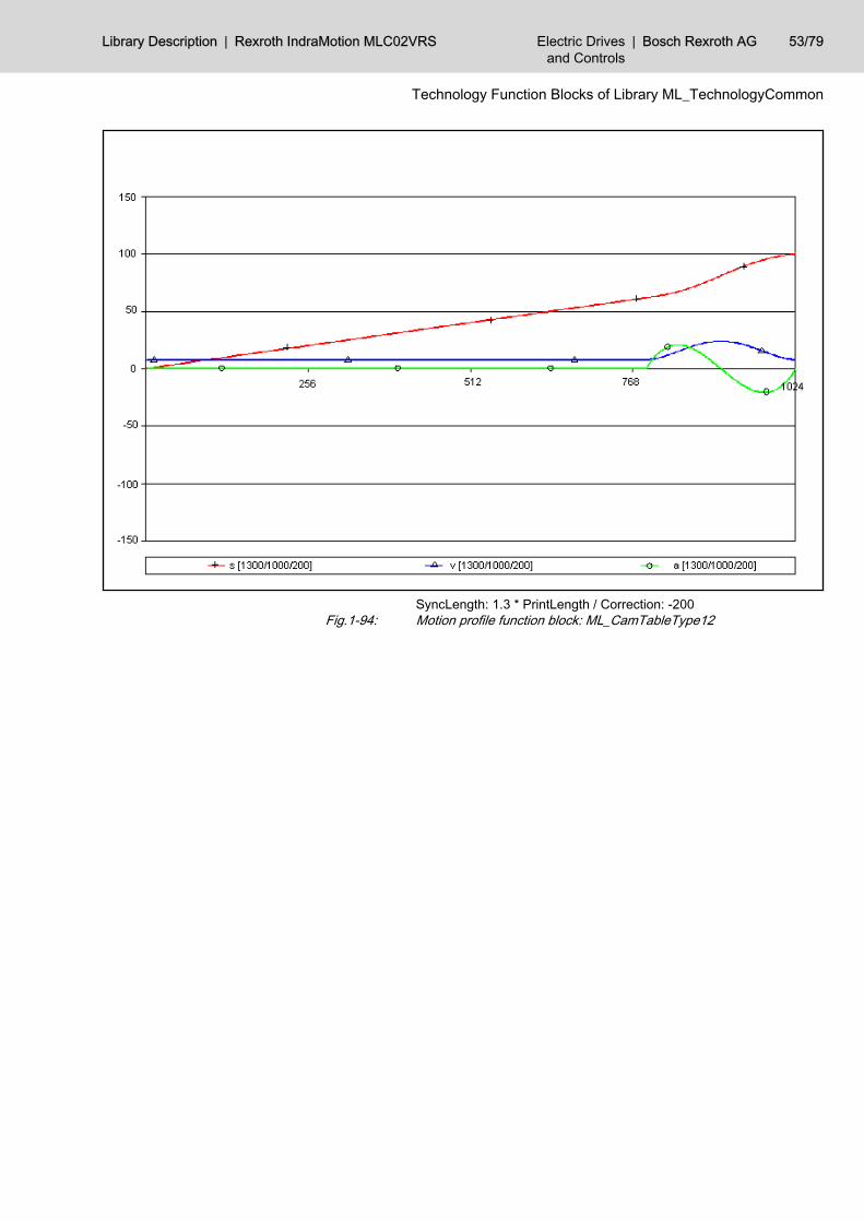
SyncLength: 1.3 * PrintLength / Correction: -200Fig.1-94: Motion profile function block: ML_CamTableType12
Library Description | Rexroth IndraMotion MLC02VRS Electric Drivesand Controls
| Bosch Rexroth AG 53/79
Technology Function Blocks of Library ML_TechnologyCommon
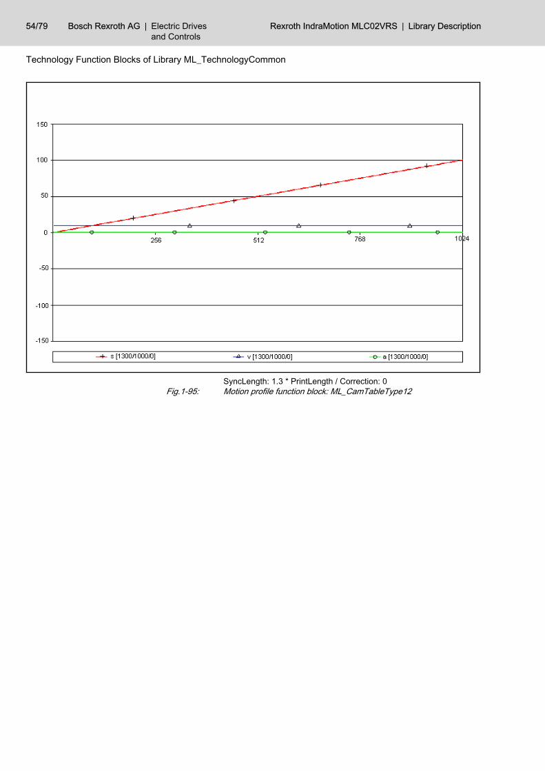
SyncLength: 1.3 * PrintLength / Correction: 0Fig.1-95: Motion profile function block: ML_CamTableType12
54/79 Bosch Rexroth AG | Electric Drivesand Controls
Rexroth IndraMotion MLC02VRS | Library Description
Technology Function Blocks of Library ML_TechnologyCommon
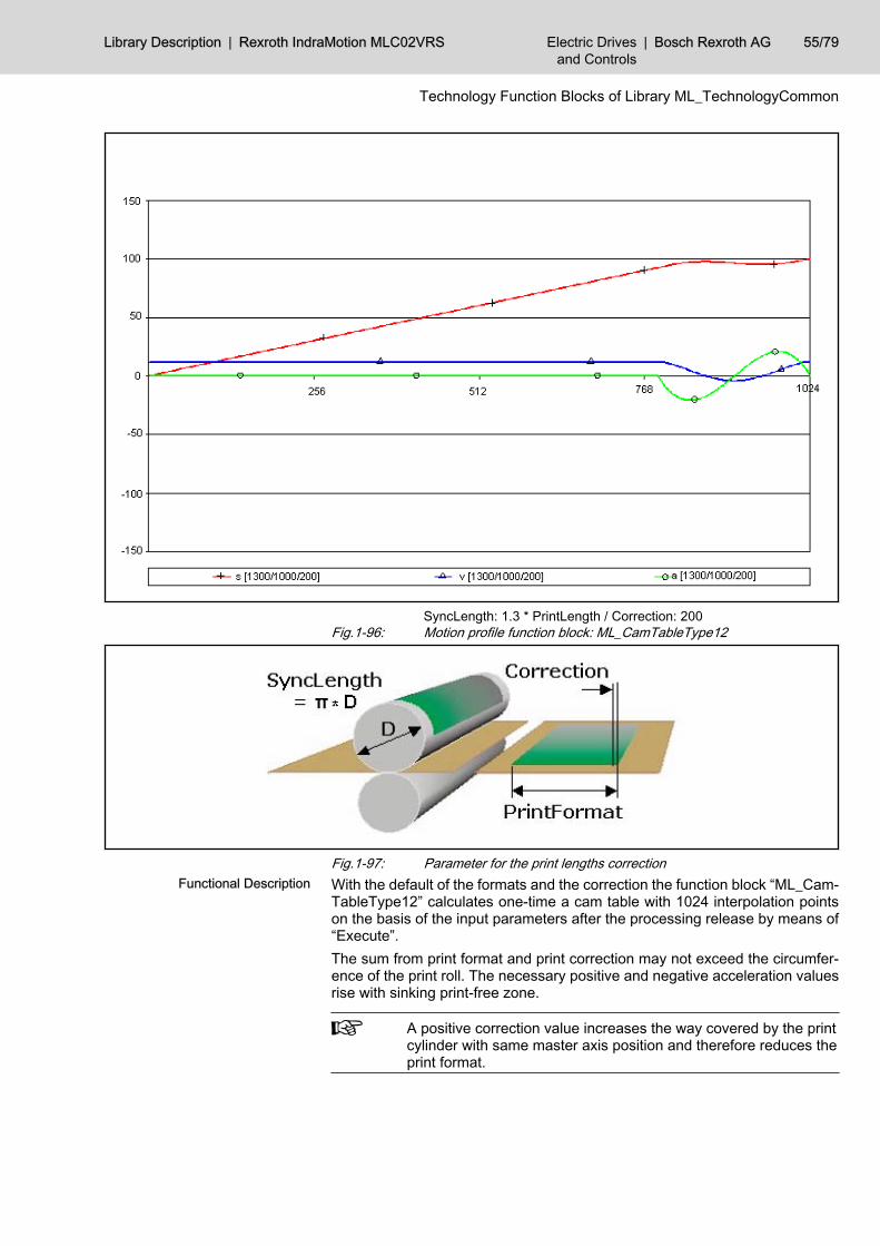
SyncLength: 1.3 * PrintLength / Correction: 200Fig.1-96: Motion profile function block: ML_CamTableType12
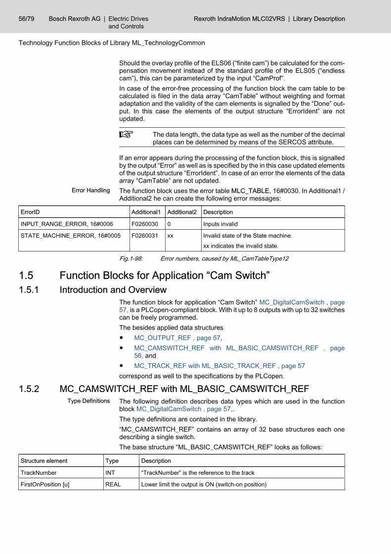
Fig.1-97: Parameter for the print lengths correctionWith the default of the formats and the correction the function block “ML_Cam‐TableType12” calculates one-time a cam table with 1024 interpolation pointson the basis of the input parameters after the processing release by means of“Execute”.The sum from print format and print correction may not exceed the circumfer‐ence of the print roll. The necessary positive and negative acceleration valuesrise with sinking print-free zone.
A positive correction value increases the way covered by the printcylinder with same master axis position and therefore reduces theprint format.
Functional Description
Library Description | Rexroth IndraMotion MLC02VRS Electric Drivesand Controls
| Bosch Rexroth AG 55/79
Technology Function Blocks of Library ML_TechnologyCommon
Should the overlay profile of the ELS06 (“finite cam”) be calculated for the com‐pensation movement instead of the standard profile of the ELS05 (“endlesscam”), this can be parameterized by the input “CamProf”.In case of the error-free processing of the function block the cam table to becalculated is filed in the data array “CamTable” without weighting and formatadaptation and the validity of the cam elements is signalled by the “Done” out‐put. In this case the elements of the output structure “ErrorIdent” are notupdated.
The data length, the data type as well as the number of the decimalplaces can be determined by means of the SERCOS attribute.
If an error appears during the processing of the function block, this is signalledby the output “Error” as well as is specified by the in this case updated elementsof the output structure “ErrorIdent”. In case of an error the elements of the dataarray “CamTable” are not updated.The function block uses the error table MLC_TABLE, 16#0030. In Additional1 /Additional2 he can create the following error messages:
ErrorID Additional1 Additional2 Description
INPUT_RANGE_ERROR, 16#0006 F0260030 0 Inputs invalid
STATE_MACHINE_ERROR, 16#0005 F0260031 xx Invalid state of the State machine.
xx indicates the invalid state.
Fig.1-98: Error numbers, caused by ML_CamTableType12
1.5 Function Blocks for Application “Cam Switch” 1.5.1 Introduction and Overview
The function block for application “Cam Switch” MC_DigitalCamSwitch , page57, is a PLCopen-compliant block. With it up to 8 outputs with up to 32 switchescan be freely programmed.The besides applied data structures● MC_OUTPUT_REF , page 57,● MC_CAMSWITCH_REF with ML_BASIC_CAMSWITCH_REF , page
56, and● MC_TRACK_REF with ML_BASIC_TRACK_REF , page 57correspond as well to the specifications by the PLCopen.
1.5.2 MC_CAMSWITCH_REF with ML_BASIC_CAMSWITCH_REF The following definition describes data types which are used in the functionblock MC_DigitalCamSwitch , page 57,.The type definitions are contained in the library.“MC_CAMSWITCH_REF” contains an array of 32 base structures each onedescribing a single switch.The base structure “ML_BASIC_CAMSWITCH_REF” looks as follows:
Structure element Type Description
TrackNumber INT “TrackNumber” is the reference to the track
FirstOnPosition [u] REAL Lower limit the output is ON (switch-on position)
Error Handling
Type Definitions
56/79 Bosch Rexroth AG | Electric Drivesand Controls
Rexroth IndraMotion MLC02VRS | Library Description
Technology Function Blocks of Library ML_TechnologyCommon
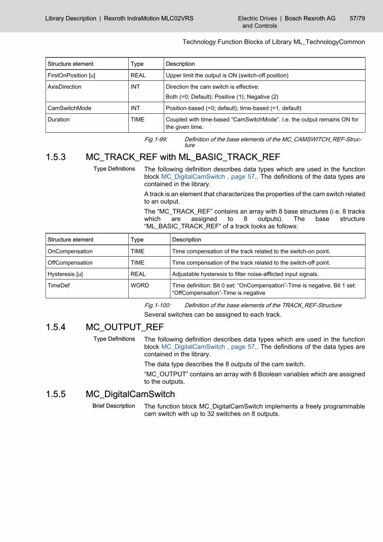
Structure element Type Description
FirstOnPosition [u] REAL Upper limit the output is ON (switch-off position)
AxisDirection INT Direction the cam switch is effective:
Both (=0; Default); Positive (1); Negative (2)
CamSwitchMode INT Position-based (=0; default); time-based (=1, default)
Duration TIME Coupled with time-based “CamSwitchMode”. I.e. the output remains ON forthe given time.
Fig.1-99: Definition of the base elements of the MC_CAMSWITCH_REF-Struc‐ture
1.5.3 MC_TRACK_REF with ML_BASIC_TRACK_REF The following definition describes data types which are used in the functionblock MC_DigitalCamSwitch , page 57,. The definitions of the data types arecontained in the library.A track is an element that characterizes the properties of the cam switch relatedto an output.The “MC_TRACK_REF” contains an array with 8 base structures (i.e. 8 trackswhich are assigned to 8 outputs). The base structure“ML_BASIC_TRACK_REF” of a track looks as follows:
Structure element Type Description
OnCompensation TIME Time compensation of the track related to the switch-on point.
OffCompensation TIME Time compensation of the track related to the switch-off point.
Hysteresis [u] REAL Adjustable hysteresis to filter noise-afflicted input signals.
TimeDef WORD Time definition: Bit 0 set: “OnCompensation”-Time is negative, Bit 1 set:“OffCompensation”-Time is negative
Fig.1-100: Definition of the base elements of the TRACK_REF-StructureSeveral switches can be assigned to each track.
1.5.4 MC_OUTPUT_REFThe following definition describes data types which are used in the functionblock MC_DigitalCamSwitch , page 57,. The definitions of the data types arecontained in the library.The data type describes the 8 outputs of the cam switch.“MC_OUTPUT” contains an array with 8 Boolean variables which are assignedto the outputs.
1.5.5 MC_DigitalCamSwitchThe function block MC_DigitalCamSwitch implements a freely programmablecam switch with up to 32 switches on 8 outputs.
Type Definitions
Type Definitions
Brief Description
Library Description | Rexroth IndraMotion MLC02VRS Electric Drivesand Controls
| Bosch Rexroth AG 57/79
Technology Function Blocks of Library ML_TechnologyCommon
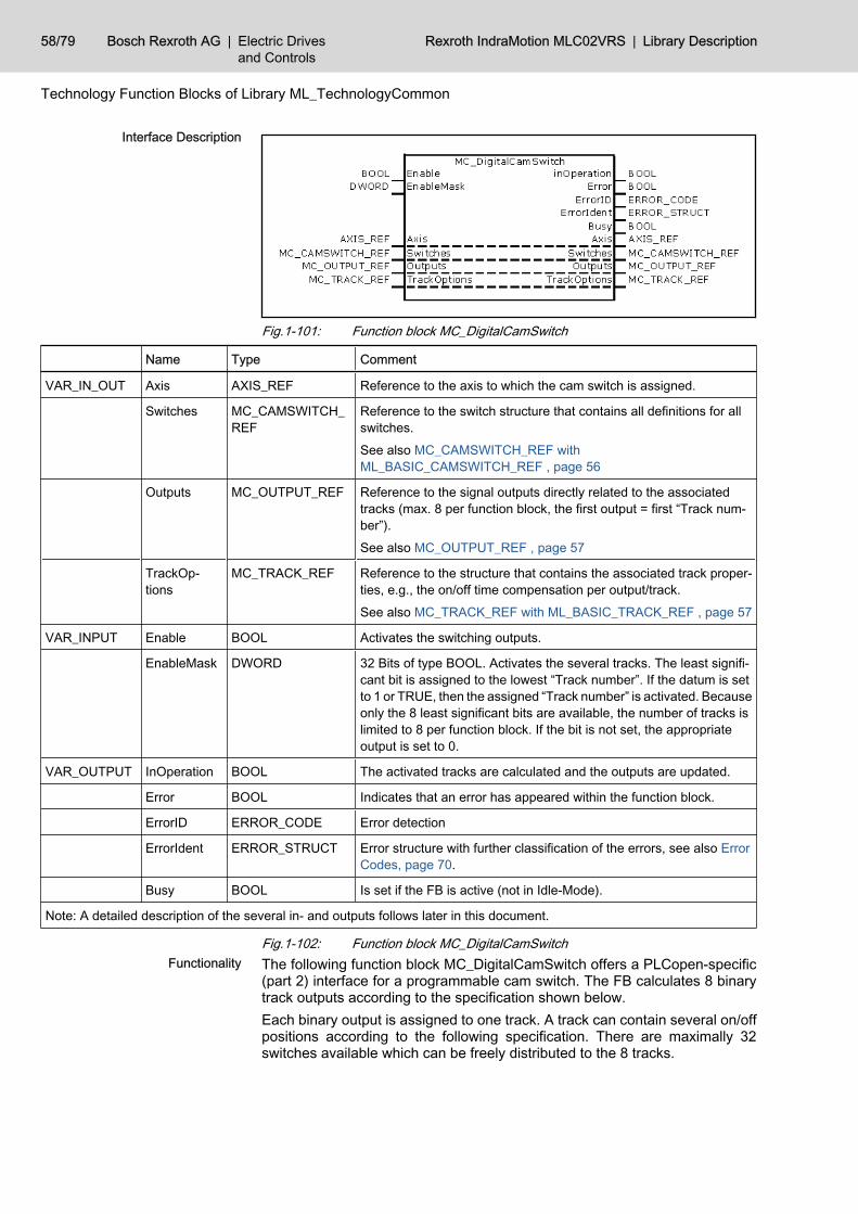
Fig.1-101: Function block MC_DigitalCamSwitch
Name Type Comment
VAR_IN_OUT Axis AXIS_REF Reference to the axis to which the cam switch is assigned.
Switches MC_CAMSWITCH_REF
Reference to the switch structure that contains all definitions for allswitches.
See also MC_CAMSWITCH_REF withML_BASIC_CAMSWITCH_REF , page 56
Outputs MC_OUTPUT_REF Reference to the signal outputs directly related to the associatedtracks (max. 8 per function block, the first output = first “Track num‐ber”).
See also MC_OUTPUT_REF , page 57
TrackOp‐tions
MC_TRACK_REF Reference to the structure that contains the associated track proper‐ties, e.g., the on/off time compensation per output/track.
See also MC_TRACK_REF with ML_BASIC_TRACK_REF , page 57
VAR_INPUT Enable BOOL Activates the switching outputs.
EnableMask DWORD 32 Bits of type BOOL. Activates the several tracks. The least signifi‐cant bit is assigned to the lowest “Track number”. If the datum is setto 1 or TRUE, then the assigned “Track number” is activated. Becauseonly the 8 least significant bits are available, the number of tracks islimited to 8 per function block. If the bit is not set, the appropriateoutput is set to 0.
VAR_OUTPUT InOperation BOOL The activated tracks are calculated and the outputs are updated.
Error BOOL Indicates that an error has appeared within the function block.
ErrorID ERROR_CODE Error detection
ErrorIdent ERROR_STRUCT Error structure with further classification of the errors, see also ErrorCodes, page 70.
Busy BOOL Is set if the FB is active (not in Idle-Mode).
Note: A detailed description of the several in- and outputs follows later in this document.
Fig.1-102: Function block MC_DigitalCamSwitchThe following function block MC_DigitalCamSwitch offers a PLCopen-specific(part 2) interface for a programmable cam switch. The FB calculates 8 binarytrack outputs according to the specification shown below.Each binary output is assigned to one track. A track can contain several on/offpositions according to the following specification. There are maximally 32switches available which can be freely distributed to the 8 tracks.
Interface Description
Functionality
58/79 Bosch Rexroth AG | Electric Drivesand Controls
Rexroth IndraMotion MLC02VRS | Library Description
Technology Function Blocks of Library ML_TechnologyCommon
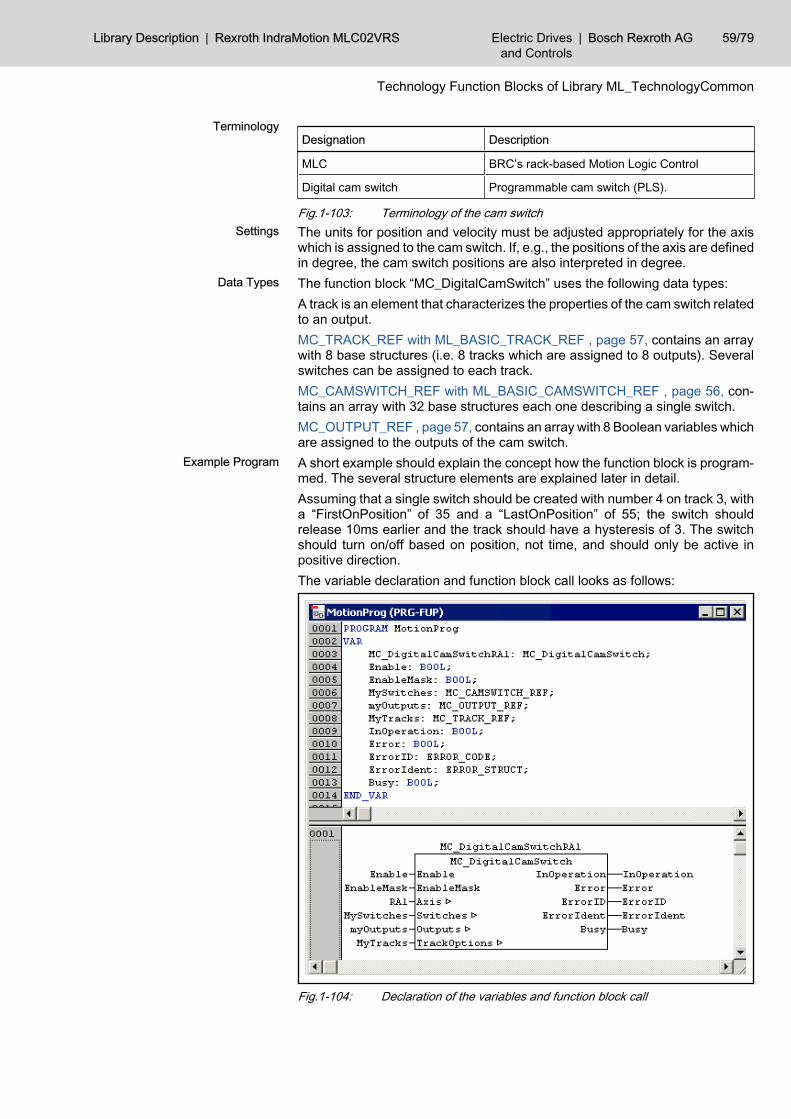
Designation Description
MLC BRC’s rack-based Motion Logic Control
Digital cam switch Programmable cam switch (PLS).
Fig.1-103: Terminology of the cam switchThe units for position and velocity must be adjusted appropriately for the axiswhich is assigned to the cam switch. If, e.g., the positions of the axis are definedin degree, the cam switch positions are also interpreted in degree.The function block “MC_DigitalCamSwitch” uses the following data types:A track is an element that characterizes the properties of the cam switch relatedto an output.MC_TRACK_REF with ML_BASIC_TRACK_REF , page 57, contains an arraywith 8 base structures (i.e. 8 tracks which are assigned to 8 outputs). Severalswitches can be assigned to each track.MC_CAMSWITCH_REF with ML_BASIC_CAMSWITCH_REF , page 56, con‐tains an array with 32 base structures each one describing a single switch.MC_OUTPUT_REF , page 57, contains an array with 8 Boolean variables whichare assigned to the outputs of the cam switch.A short example should explain the concept how the function block is program‐med. The several structure elements are explained later in detail.Assuming that a single switch should be created with number 4 on track 3, witha “FirstOnPosition” of 35 and a “LastOnPosition” of 55; the switch shouldrelease 10ms earlier and the track should have a hysteresis of 3. The switchshould turn on/off based on position, not time, and should only be active inpositive direction.The variable declaration and function block call looks as follows:
Fig.1-104: Declaration of the variables and function block call
Terminology
Settings
Data Types
Example Program
Library Description | Rexroth IndraMotion MLC02VRS Electric Drivesand Controls
| Bosch Rexroth AG 59/79
Technology Function Blocks of Library ML_TechnologyCommon
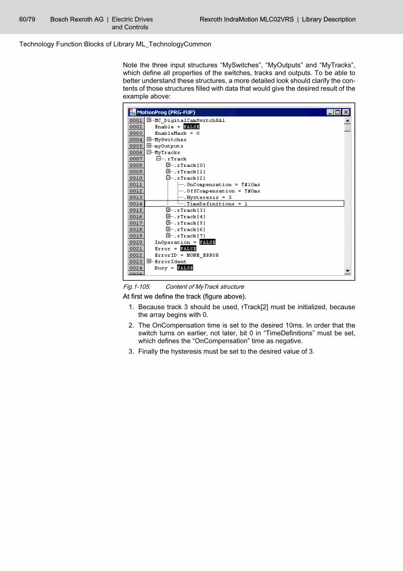
Note the three input structures “MySwitches”, “MyOutputs” and “MyTracks”,which define all properties of the switches, tracks and outputs. To be able tobetter understand these structures, a more detailed look should clarify the con‐tents of those structures filled with data that would give the desired result of theexample above:
Fig.1-105: Content of MyTrack structureAt first we define the track (figure above).
1. Because track 3 should be used, rTrack[2] must be initialized, becausethe array begins with 0.
2. The OnCompensation time is set to the desired 10ms. In order that theswitch turns on earlier, not later, bit 0 in “TimeDefinitions” must be set,which defines the “OnCompensation” time as negative.
3. Finally the hysteresis must be set to the desired value of 3.
60/79 Bosch Rexroth AG | Electric Drivesand Controls
Rexroth IndraMotion MLC02VRS | Library Description
Technology Function Blocks of Library ML_TechnologyCommon
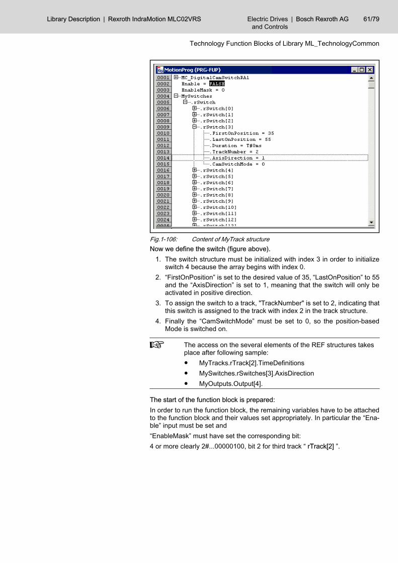
Fig.1-106: Content of MyTrack structureNow we define the switch (figure above).
1. The switch structure must be initialized with index 3 in order to initializeswitch 4 because the array begins with index 0.
2. “FirstOnPosition” is set to the desired value of 35, “LastOnPosition” to 55and the “AxisDirection” is set to 1, meaning that the switch will only beactivated in positive direction.
3. To assign the switch to a track, "TrackNumber" is set to 2, indicating thatthis switch is assigned to the track with index 2 in the track structure.
4. Finally the “CamSwitchMode” must be set to 0, so the position-basedMode is switched on.
The access on the several elements of the REF structures takesplace after following sample:● MyTracks.rTrack[2].TimeDefinitions● MySwitches.rSwitches[3].AxisDirection● MyOutputs.Output[4].
The start of the function block is prepared:In order to run the function block, the remaining variables have to be attachedto the function block and their values set appropriately. In particular the “Ena‐ble” input must be set and“EnableMask” must have set the corresponding bit:4 or more clearly 2#...00000100, bit 2 for third track “ rTrack[2] ”.
Library Description | Rexroth IndraMotion MLC02VRS Electric Drivesand Controls
| Bosch Rexroth AG 61/79
Technology Function Blocks of Library ML_TechnologyCommon
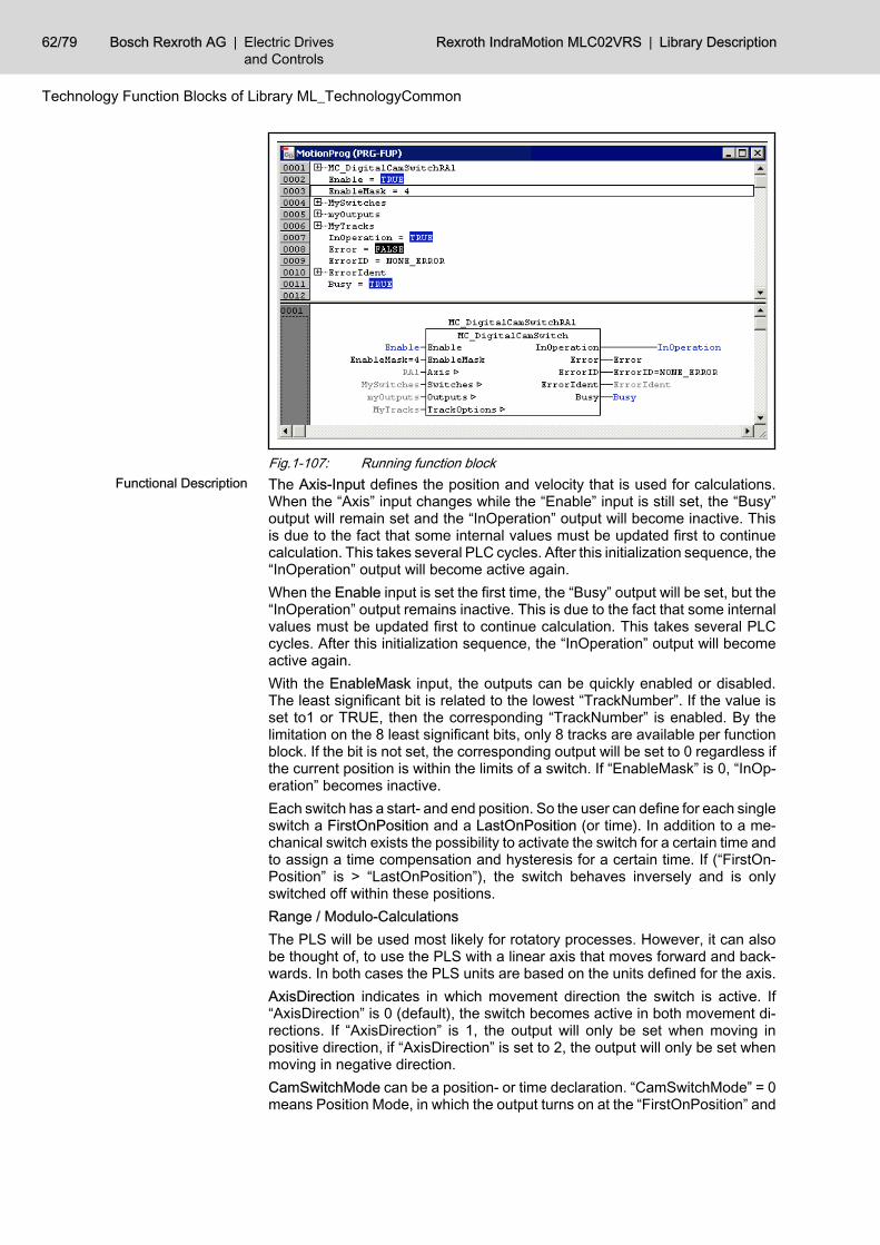
Fig.1-107: Running function blockThe Axis-Input defines the position and velocity that is used for calculations.When the “Axis” input changes while the “Enable” input is still set, the “Busy”output will remain set and the “InOperation” output will become inactive. Thisis due to the fact that some internal values must be updated first to continuecalculation. This takes several PLC cycles. After this initialization sequence, the“InOperation” output will become active again.When the Enable input is set the first time, the “Busy” output will be set, but the“InOperation” output remains inactive. This is due to the fact that some internalvalues must be updated first to continue calculation. This takes several PLCcycles. After this initialization sequence, the “InOperation” output will becomeactive again.With the EnableMask input, the outputs can be quickly enabled or disabled.The least significant bit is related to the lowest “TrackNumber”. If the value isset to1 or TRUE, then the corresponding “TrackNumber” is enabled. By thelimitation on the 8 least significant bits, only 8 tracks are available per functionblock. If the bit is not set, the corresponding output will be set to 0 regardless ifthe current position is within the limits of a switch. If “EnableMask” is 0, “InOp‐eration” becomes inactive.Each switch has a start- and end position. So the user can define for each singleswitch a FirstOnPosition and a LastOnPosition (or time). In addition to a me‐chanical switch exists the possibility to activate the switch for a certain time andto assign a time compensation and hysteresis for a certain time. If (“FirstOn‐Position” is > “LastOnPosition”), the switch behaves inversely and is onlyswitched off within these positions.Range / Modulo-CalculationsThe PLS will be used most likely for rotatory processes. However, it can alsobe thought of, to use the PLS with a linear axis that moves forward and back‐wards. In both cases the PLS units are based on the units defined for the axis.AxisDirection indicates in which movement direction the switch is active. If“AxisDirection” is 0 (default), the switch becomes active in both movement di‐rections. If “AxisDirection” is 1, the output will only be set when moving inpositive direction, if “AxisDirection” is set to 2, the output will only be set whenmoving in negative direction.CamSwitchMode can be a position- or time declaration. “CamSwitchMode” = 0means Position Mode, in which the output turns on at the “FirstOnPosition” and
Functional Description
62/79 Bosch Rexroth AG | Electric Drivesand Controls
Rexroth IndraMotion MLC02VRS | Library Description
Technology Function Blocks of Library ML_TechnologyCommon
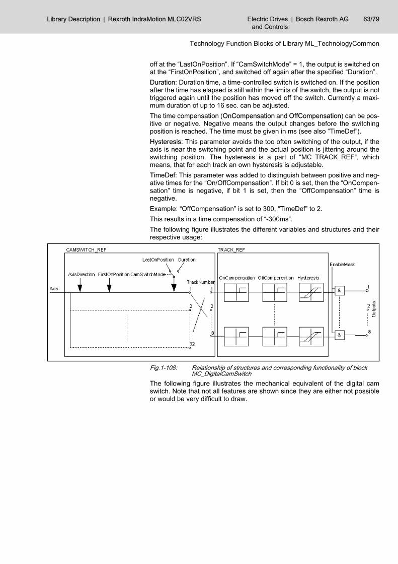
off at the “LastOnPosition”. If “CamSwitchMode” = 1, the output is switched onat the “FirstOnPosition”, and switched off again after the specified “Duration”.Duration: Duration time, a time-controlled switch is switched on. If the positionafter the time has elapsed is still within the limits of the switch, the output is nottriggered again until the position has moved off the switch. Currently a maxi‐mum duration of up to 16 sec. can be adjusted.The time compensation (OnCompensation and OffCompensation) can be pos‐itive or negative. Negative means the output changes before the switchingposition is reached. The time must be given in ms (see also “TimeDef”).Hysteresis: This parameter avoids the too often switching of the output, if theaxis is near the switching point and the actual position is jittering around theswitching position. The hysteresis is a part of “MC_TRACK_REF”, whichmeans, that for each track an own hysteresis is adjustable.TimeDef: This parameter was added to distinguish between positive and neg‐ative times for the “On/OffCompensation”. If bit 0 is set, then the “OnCompen‐sation” time is negative, if bit 1 is set, then the “OffCompensation” time isnegative.Example: “OffCompensation” is set to 300, “TimeDef” to 2.This results in a time compensation of “-300ms”.The following figure illustrates the different variables and structures and theirrespective usage:
Fig.1-108: Relationship of structures and corresponding functionality of blockMC_DigitalCamSwitch
The following figure illustrates the mechanical equivalent of the digital camswitch. Note that not all features are shown since they are either not possibleor would be very difficult to draw.
Library Description | Rexroth IndraMotion MLC02VRS Electric Drivesand Controls
| Bosch Rexroth AG 63/79
Technology Function Blocks of Library ML_TechnologyCommon
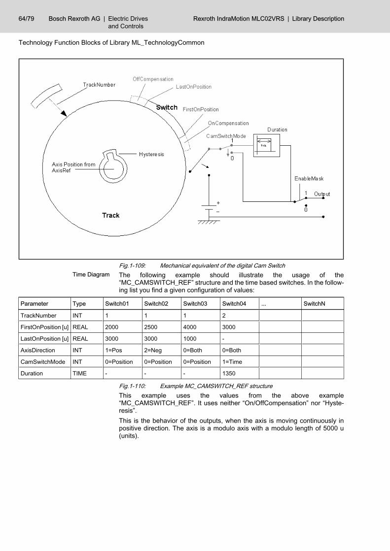
Fig.1-109: Mechanical equivalent of the digital Cam SwitchThe following example should illustrate the usage of the“MC_CAMSWITCH_REF” structure and the time based switches. In the follow‐ing list you find a given configuration of values:
Parameter Type Switch01 Switch02 Switch03 Switch04 ... SwitchN
TrackNumber INT 1 1 1 2
FirstOnPosition [u] REAL 2000 2500 4000 3000
LastOnPosition [u] REAL 3000 3000 1000 -
AxisDirection INT 1=Pos 2=Neg 0=Both 0=Both
CamSwitchMode INT 0=Position 0=Position 0=Position 1=Time
Duration TIME - - - 1350
Fig.1-110: Example MC_CAMSWITCH_REF structureThis example uses the values from the above example“MC_CAMSWITCH_REF”. It uses neither “On/OffCompensation” nor “Hyste‐resis”.This is the behavior of the outputs, when the axis is moving continuously inpositive direction. The axis is a modulo axis with a modulo length of 5000 u(units).
Time Diagram
64/79 Bosch Rexroth AG | Electric Drivesand Controls
Rexroth IndraMotion MLC02VRS | Library Description
Technology Function Blocks of Library ML_TechnologyCommon
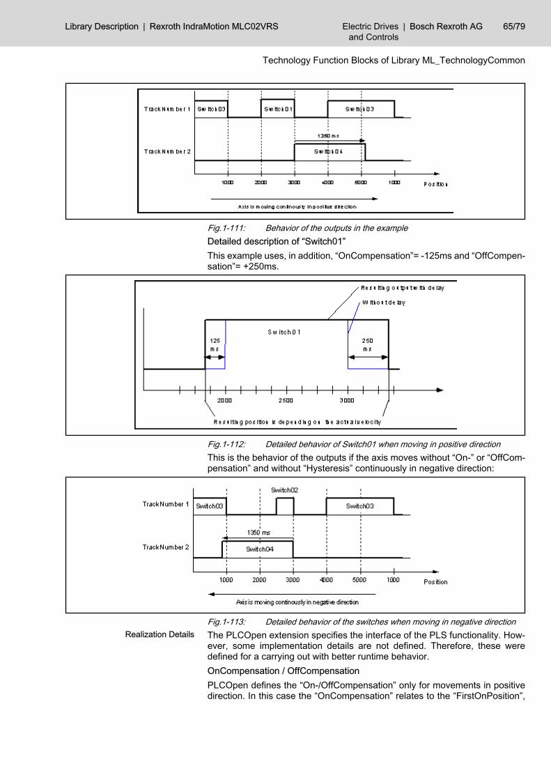
Fig.1-111: Behavior of the outputs in the exampleDetailed description of “Switch01”This example uses, in addition, “OnCompensation”= -125ms and “OffCompen‐sation”= +250ms.
Fig.1-112: Detailed behavior of Switch01 when moving in positive directionThis is the behavior of the outputs if the axis moves without “On-” or “OffCom‐pensation” and without “Hysteresis” continuously in negative direction:
Fig.1-113: Detailed behavior of the switches when moving in negative directionThe PLCOpen extension specifies the interface of the PLS functionality. How‐ever, some implementation details are not defined. Therefore, these weredefined for a carrying out with better runtime behavior.OnCompensation / OffCompensationPLCOpen defines the “On-/OffCompensation” only for movements in positivedirection. In this case the “OnCompensation” relates to the “FirstOnPosition”,
Realization Details
Library Description | Rexroth IndraMotion MLC02VRS Electric Drivesand Controls
| Bosch Rexroth AG 65/79
Technology Function Blocks of Library ML_TechnologyCommon
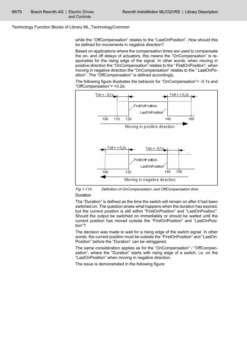
while the “OffCompensation” relates to the “LastOnPosition”. How should thisbe defined for movements in negative direction?Based on applications where the compensation times are used to compensatethe on- and off delays of actuators, this means the “OnCompensation” is re‐sponsible for the rising edge of the signal. In other words: when moving inpositive direction the “OnCompensation” relates to the “ FirstOnPosition”, whenmoving in negative direction the “OnCompensation” relates to the “ LastOnPo‐sition”. The “OffCompensation” is defined accordingly.The following figure illustrates the behavior for “OnCompensation”= -0.1s and“OffCompensation”= +0.2s:
Fig.1-114: Definition of OnCompensation- and OffCompensation timeDurationThe “Duration” is defined as the time the switch will remain on after it had beenswitched on. The question arises what happens when the duration has expired,but the current position is still within “FirstOnPosition” and “LastOnPosition”.Should the output be switched on immediately or should be waited until thecurrent position has moved outside the “FirstOnPosition” and “LastOnPosi‐tion”?The decision was made to wait for a rising edge of the switch signal. In otherwords: the current position must be outside the “FirstOnPosition” and “LastOn‐Position” before the “Duration” can be retriggered.The same consideration applies as for the “OnCompensation” / “OffCompen‐sation”, where the “Duration” starts with rising edge of a switch, i.e. on the“LastOnPosition” when moving in negative direction.The issue is demonstrated in the following figure:
66/79 Bosch Rexroth AG | Electric Drivesand Controls
Rexroth IndraMotion MLC02VRS | Library Description
Technology Function Blocks of Library ML_TechnologyCommon
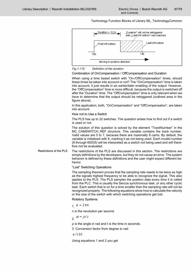
Fig.1-115: Definition of the durationCombination of OnCompensation / OffCompensation and DurationWhen using a time based switch with “On-/OffCompensation” times, shouldthese times be taken into account or not? The “OnCompensation” time is takeninto account, it just results in an earlier/later enabling of the output. However,the “OffCompensation” time is more difficult, because the output is switched offafter the “Duration” time. The “OffCompensation” time is only relevant when wehave to determine that the output should be retriggered (outlined area in thefigure above).In this application, both, “OnCompensation” and “OffCompensation”, are takeninto account.How not to Use a SwitchThe PLS has up to 32 switches. The question arises how to find out if a switchis used or not.The solution of this question is solved by the element “TrackNumber” in theMC_CAMSWITCH_REF structure. This variable contains the track number.Valid values are 0 to 7, because there are maximally 8 cams. By default, thevariable is initialized with 8, marking it as not being used. Each invalid number(8 through 65535) will be interpreted as a switch not being used and will there‐fore not be evaluated.The restrictions of the PLS are discussed in this section. The restrictions aresimply definitions by the developers, but they do not cause an error. The systembehavior is defined by these definitions and the user might expect different be‐havior.“Lost” Switching OperationsThe sampling theorem proves that the sampling rate needs to be twice as highas the signals highest frequency to be able to recognize the signal. This alsoapplies to the PLS. The PLS samples the position data every time it is calledfrom the PLC. This is usually the Sercos synchronous task, or any other cyclictask. Each switch that is on for a time smaller than the sampling rate will not berecognized properly. The following equations show how to calculate the velocityor the size of the switch with which switching operations get lost.Rotatory Systems:
1. n is the revolution per second.
2. ρ is the angle in rad and t is the time in seconds.3. Conversion factor from degree to rad:
Using equations 1 and 2 you get
Restrictions of the PLS
Library Description | Rexroth IndraMotion MLC02VRS Electric Drivesand Controls
| Bosch Rexroth AG 67/79
Technology Function Blocks of Library ML_TechnologyCommon
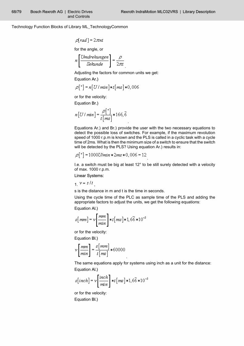
for the angle, or
.Adjusting the factors for common units we get:Equation Ar.)
or for the velocity:Equation Br.)
.Equations Ar.) and Br.) provide the user with the two necessary equations todetect the possible loss of switches. For example, if the maximum revolutionspeed of 1000 r.p.m is known and the PLS is called in a cyclic task with a cycletime of 2ms. What is then the minimum size of a switch to ensure that the switchwill be detected by the PLS? Using equation Ar.) results in:
.I.e. a switch must be big at least 12° to be still surely detected with a velocityof max. 1000 r.p.m.Linear Systems:
1. ,s is the distance in m and t is the time in seconds.Using the cycle time of the PLC as sample time of the PLS and adding theappropriate factors to adjust the units, we get the following equations:Equation Al.)
or for the velocity:Equation Bl.)
.The same equations apply for systems using inch as a unit for the distance:Equation Al.)
or for the velocity:Equation Bl.)
68/79 Bosch Rexroth AG | Electric Drivesand Controls
Rexroth IndraMotion MLC02VRS | Library Description
Technology Function Blocks of Library ML_TechnologyCommon
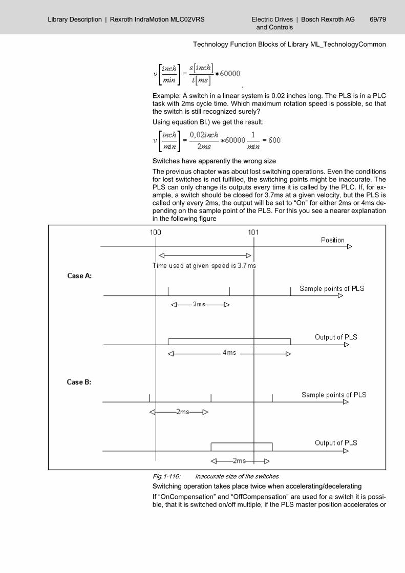
.Example: A switch in a linear system is 0.02 inches long. The PLS is in a PLCtask with 2ms cycle time. Which maximum rotation speed is possible, so thatthe switch is still recognized surely?Using equation Bl.) we get the result:
Switches have apparently the wrong sizeThe previous chapter was about lost switching operations. Even the conditionsfor lost switches is not fulfilled, the switching points might be inaccurate. ThePLS can only change its outputs every time it is called by the PLC. If, for ex‐ample, a switch should be closed for 3.7ms at a given velocity, but the PLS iscalled only every 2ms, the output will be set to “On” for either 2ms or 4ms de‐pending on the sample point of the PLS. For this you see a nearer explanationin the following figure
Fig.1-116: Inaccurate size of the switchesSwitching operation takes place twice when accelerating/deceleratingIf “OnCompensation” and “OffCompensation” are used for a switch it is possi‐ble, that it is switched on/off multiple, if the PLS master position accelerates or
Library Description | Rexroth IndraMotion MLC02VRS Electric Drivesand Controls
| Bosch Rexroth AG 69/79
Technology Function Blocks of Library ML_TechnologyCommon
decelerates. This is due to the fact, that the PLS assumes a constant velocity,what is not given under certain circumstances, however. The bigger problemoccurs when decelerating. Some considerations, when a switch can be activa‐ted several times, will follow.We can form the following equations:
1.) whereas sv is the distance, which is traveled at a given velocity v0 in the “On‐Compensation” time tlead.
2.) sb is the distance, which is needed to decelerate with a given start velocity v0and deceleration a in the time t.Furthermore the common equations:
3.) or .The “OnCompensation” time of a programmed cam switch “moves” the switchtowards lower position according to equation 1.). The distance needed to cometo a stand still with a given velocity can be calculated by equation 2.).Therefore, the general rule is:When the position with v= v0 is reached, so that the output of a programmedcam switch with “OnCompensation” time should be switched on – and the inputposition is stopped in such a way that the stop position is simultaneously theswitch on position of the programmed cam switch without “OnCompensation”time (v= 0), then the output is not switched off in-between.If we set equation 1.) equate with equation 2.), we get the equation with whichthe switch is switched on only once. If we decelerate a little bit faster, then theswitch will be switched on multiple.
4.) .In equation 4.) it can be seen that the starting velocity v0, at which it is possiblethat a switch turns on more than once, is getting bigger with increasing the“OnCompensation” time tlead or deceleration a.
There is no solution for this problem. You can only hold the “OnCompensa‐tion” time and deceleration for the wished application small as possible.Another possibility is to use the “Hysteresis”, so that the variations are consid‐ered on account of the acceleration/deceleration in it.The same thoughts can be applied for the acceleration and/or negative veloc‐ities.The function block uses the error table MLC_TABLE, 16#0030. In Additional1 /Additional2 he can create the following error messages:
Error Codes
70/79 Bosch Rexroth AG | Electric Drivesand Controls
Rexroth IndraMotion MLC02VRS | Library Description
Technology Function Blocks of Library ML_TechnologyCommon
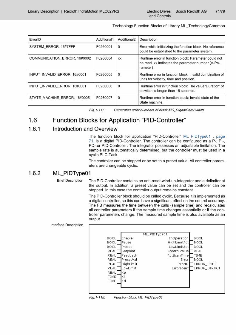
ErrorID Additional1 Additional2 Description
SYSTEM_ERROR, 16#7FFF F0260001 0 Error while initializing the function block. No referencecould be established to the parameter system.
COMMUNICATION_ERROR, 16#0002 F0260004 xx Runtime error in function block: Parameter could notbe read. xx indicates the parameter number (A-Pa‐rameter)
INPUT_INVALID_ERROR, 16#0001 F0260005 0 Runtime error in function block: Invalid combination ofunits for velocity, time and position.
INPUT_INVALID_ERROR, 16#0001 F0260006 0 Runtime error in function block: The value 'Duration' ofa switch is longer than 16 seconds.
STATE_MACHINE_ERROR, 16#0005 F0260007 0 Runtime error in function block: Invalid state of theState machine.
Fig.1-117: Generated error numbers of block MC_DigitalCamSwitch
1.6 Function Blocks for Application “PID-Controller” 1.6.1 Introduction and Overview
The function block for application “PID-Controller” ML_PIDType01 , page71, is a digital PID-Controller. The controller can be configured as a P-, PI-,PD- or PID-Controller. The integrator possesses an adjustable limitation. Thesample rate is automatically determined, but the controller must be used in acyclic PLC-Task.The controller can be stopped or be set to a preset value. All controller param‐eters are changeable cyclic.
1.6.2 ML_PIDType01The PID-Controller contains an anti-reset-wind-up-integrator and a delimiter atthe output. In addition, a preset value can be set and the controller can bestopped. In this case the controller output remains constant.The PID-Controller block should be called cyclic. Because it is implemented asa digital controller, so this can have a significant effect on the control accuracy.The FB measures the time between the calls (sample time) and recalculatesall controller parameters if the sample time changes essentially or if the con‐troller parameters change. The measured sample time is also available as anoutput.
Fig.1-118: Function block ML_PIDType01
Brief Description
Interface Description
Library Description | Rexroth IndraMotion MLC02VRS Electric Drivesand Controls
| Bosch Rexroth AG 71/79
Technology Function Blocks of Library ML_TechnologyCommon
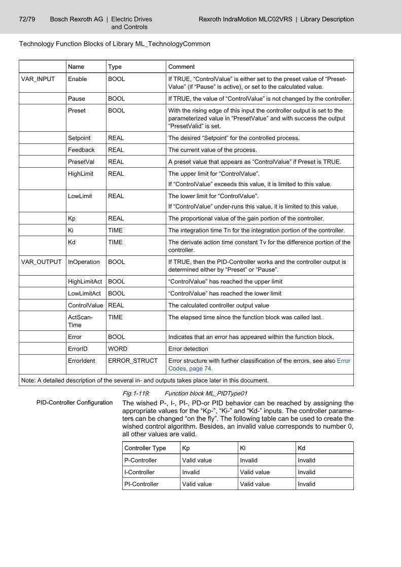
Name Type Comment
VAR_INPUT Enable BOOL If TRUE, “ControlValue” is either set to the preset value of “Preset‐Value” (if “Pause” is active), or set to the calculated value.
Pause BOOL If TRUE, the value of “ControlValue” is not changed by the controller.
Preset BOOL With the rising edge of this input the controller output is set to theparameterized value in “PresetValue” and with success the output“PresetValid” is set.
Setpoint REAL The desired “Setpoint” for the controlled process.
Feedback REAL The current value of the process.
PresetVal REAL A preset value that appears as “ControlValue” if Preset is TRUE.
HighLimit REAL The upper limit for “ControlValue”.
If “ControlValue” exceeds this value, it is limited to this value.
LowLimit REAL The lower limit for “ControlValue”.
If “ControlValue” under-runs this value, it is limited to this value.
Kp REAL The proportional value of the gain portion of the controller.
Ki TIME The integration time Tn for the integration portion of the controller.
Kd TIME The derivate action time constant Tv for the difference portion of thecontroller.
VAR_OUTPUT InOperation BOOL If TRUE, then the PID-Controller works and the controller output isdetermined either by “Preset” or “Pause”.
HighLimitAct BOOL “ControlValue” has reached the upper limit
LowLimitAct BOOL “ControlValue” has reached the lower limit
ControlValue REAL The calculated controller output value
ActScan‐Time
TIME The elapsed time since the function block was called last.
Error BOOL Indicates that an error has appeared within the function block.
ErrorID WORD Error detection
ErrorIdent ERROR_STRUCT Error structure with further classification of the errors, see also ErrorCodes, page 74.
Note: A detailed description of the several in- and outputs takes place later in this document.
Fig.1-119: Function block ML_PIDType01The wished P-, I-, PI-, PD-or PID behavior can be reached by assigning theappropriate values for the “Kp-”, “Ki-” and “Kd-” inputs. The controller parame‐ters can be changed “on the fly”. The following table can be used to create thewished control algorithm. Besides, an invalid value corresponds to number 0,all other values are valid.
Controller Type Kp Ki Kd
P-Controller Valid value Invalid Invalid
I-Controller Invalid Valid value Invalid
PI-Controller Valid value Valid value Invalid
PID-Controller Configuration
72/79 Bosch Rexroth AG | Electric Drivesand Controls
Rexroth IndraMotion MLC02VRS | Library Description
Technology Function Blocks of Library ML_TechnologyCommon
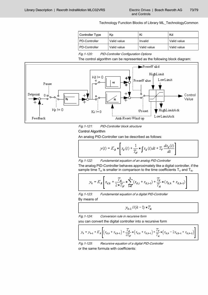
Controller Type Kp Ki Kd
PD-Controller Valid value Invalid Valid value
PD-Controller Valid value Valid value Valid value
Fig.1-120: PID-Controller Configuration OptionsThe control algorithm can be represented as the following block diagram:
Fig.1-121: PID-Controller block structureControl AlgorithmAn analog PID-Controller can be described as follows:
Fig.1-122: Fundamental equation of an analog PID-ControllerThe analog PID-Controller behaves approximately like a digital controller, if thesample time TA is smaller in comparison to the time coefficients TV and TN.
Fig.1-123: Fundamental equation of a digital PID-ControllerBy means of
Fig.1-124: Conversion rule in recursive formyou can convert the digital controller into a recursive form
Fig.1-125: Recursive equation of a digital PID-Controlleror the same formula with coefficients:
Library Description | Rexroth IndraMotion MLC02VRS Electric Drivesand Controls
| Bosch Rexroth AG 73/79
Technology Function Blocks of Library ML_TechnologyCommon
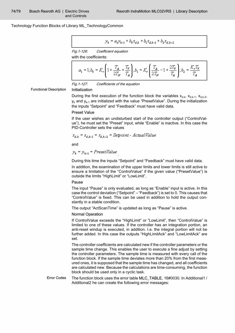
Fig.1-126: Coefficient equationwith the coefficients:
Fig.1-127: Coefficients of the equationInitializationDuring the first execution of the function block the variables xd,k, xd,k-1, xd,k-2,yk and yk-1 are initialized with the value “PresetValue”. During the initializationthe inputs “Setpoint” and “Feedback” must have valid data.Preset ValueIf the user wishes an undisturbed start of the controller output (“ControlVal‐ue”), he must set the “Preset” input, while “Enable” is inactive. In this case thePID-Controller sets the values
and
.During this time the inputs “Setpoint” and “Feedback” must have valid data.In addition, the examination of the upper limits and lower limits is still active toensure a limitation of the “ControlValue” if the given value (“PresetValue”) isoutside the limits “HighLimit” or “LowLimit”.PauseThe input “Pause” is only evaluated, as long as “Enable” input is active. In thiscase the control deviation (“Setpoint” – “Feedback”) is set to 0. This causes that“ControlValue” is fixed. This can be used in addition to hold the output con‐stantly in a stable condition.The output “ActScanTime” is updated as long as “Pause” is active.Normal OperationIf ControlValue exceeds the “HighLimit” or “LowLimit”, then “ControlValue” islimited to one of these values. If the controller has an integration portion, ananti-reset windup is executed, in addition. I.e. the integral portion will not befurther added. In this case the outputs “HighLimitAck” and “LowLimitAck” areset.The controller coefficients are calculated new if the controller parameters or thesample time change. This enables the user to execute a fine adjust by settingthe controller parameters. The sample time is measured with every call of thefunction block. If the sample time deviates more than 20% from the first meas‐ured ones, it is supposed that the sample time has changed, and all coefficientsare calculated new. Because the calculations are time-consuming, the functionblock should be used only in a cyclic task.The function block uses the error table MLC_TABLE, 16#0030. In Additional1 /Additional2 he can create the following error messages:
Functional Description
Error Codes
74/79 Bosch Rexroth AG | Electric Drivesand Controls
Rexroth IndraMotion MLC02VRS | Library Description
Technology Function Blocks of Library ML_TechnologyCommon
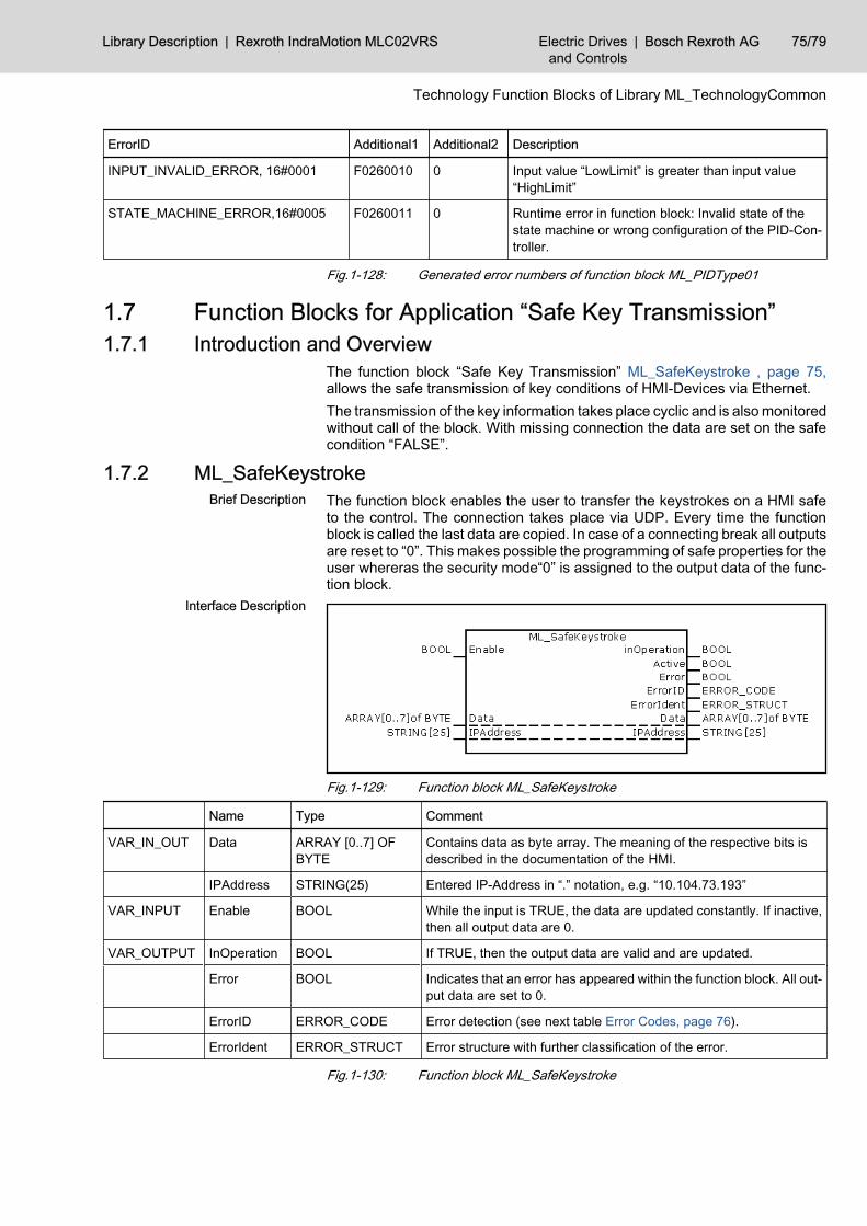
ErrorID Additional1 Additional2 Description
INPUT_INVALID_ERROR, 16#0001 F0260010 0 Input value “LowLimit” is greater than input value“HighLimit”
STATE_MACHINE_ERROR,16#0005 F0260011 0 Runtime error in function block: Invalid state of thestate machine or wrong configuration of the PID-Con‐troller.
Fig.1-128: Generated error numbers of function block ML_PIDType01
1.7 Function Blocks for Application “Safe Key Transmission” 1.7.1 Introduction and Overview
The function block “Safe Key Transmission” ML_SafeKeystroke , page 75,allows the safe transmission of key conditions of HMI-Devices via Ethernet.The transmission of the key information takes place cyclic and is also monitoredwithout call of the block. With missing connection the data are set on the safecondition “FALSE”.
1.7.2 ML_SafeKeystrokeThe function block enables the user to transfer the keystrokes on a HMI safeto the control. The connection takes place via UDP. Every time the functionblock is called the last data are copied. In case of a connecting break all outputsare reset to “0”. This makes possible the programming of safe properties for theuser whereras the security mode“0” is assigned to the output data of the func‐tion block.
Fig.1-129: Function block ML_SafeKeystroke
Name Type Comment
VAR_IN_OUT Data ARRAY [0..7] OFBYTE
Contains data as byte array. The meaning of the respective bits isdescribed in the documentation of the HMI.
IPAddress STRING(25) Entered IP-Address in “.” notation, e.g. “10.104.73.193”
VAR_INPUT Enable BOOL While the input is TRUE, the data are updated constantly. If inactive,then all output data are 0.
VAR_OUTPUT InOperation BOOL If TRUE, then the output data are valid and are updated.
Error BOOL Indicates that an error has appeared within the function block. All out‐put data are set to 0.
ErrorID ERROR_CODE Error detection (see next table Error Codes, page 76).
ErrorIdent ERROR_STRUCT Error structure with further classification of the error.
Fig.1-130: Function block ML_SafeKeystroke
Brief Description
Interface Description
Library Description | Rexroth IndraMotion MLC02VRS Electric Drivesand Controls
| Bosch Rexroth AG 75/79
Technology Function Blocks of Library ML_TechnologyCommon

The function block uses the error table MLC_TABLE, 16#0030. In Additional1 /Additional2 he can create the following error messages:
ErrorID Additional1 Additional2 Description
INPUT_INVALID_ERROR,16#0001 F0260020 0 Wrong IP-Syntax
COMMUNICATION_ERROR,16#0002 F0260021 0 Unknown IP-Address or no connection
DEVICE_ERROR, 16#0008 F0260022 0 Invalid internal buffer size
STATE_MACHINE_ERROR, 16#0005 F0260022 0 Invalid state of the State machine
Fig.1-131: Generated error numbers of function block ML_SafeKeystroke
Error Codes
76/79 Bosch Rexroth AG | Electric Drivesand Controls
Rexroth IndraMotion MLC02VRS | Library Description
Technology Function Blocks of Library ML_TechnologyCommon

2 Service & Support2.1 Helpdesk
Our service helpdesk at our headquarters in Lohr, Germany, will assist you withall kinds of enquiries.Contact us:● By phone through the Service Call Entry Center,
Mo - Fr 7:00 am - 6:00 pm CET+49 (0) 9352 40 50 60
● By Fax+49 (0) 9352 40 49 41
● By email: [email protected]
2.2 Service HotlineOut of helpdesk hours please contact our German service department directly:+49 (0) 171 333 88 26or+49 (0) 172 660 04 06Hotline numbers for other countries can be found in the addresses of eachregion (see below).
2.3 InternetAdditional notes regarding service, maintenance and training, as well as thecurrent addresses of our sales and service offices can be found onhttp://www.boschrexroth.comOutwith Germany please contact our sales/service office in your area first.
2.4 Helpful InformationFor quick and efficient help please have the following information ready:● detailed description of the fault and the circumstances● information on the type plate of the affected products, especially type co‐
des and serial numbers● your phone / fax numbers and e-mail address so we can contact you in
case of questions
Library Description | Rexroth IndraMotion MLC02VRS Electric Drivesand Controls
| Bosch Rexroth AG 77/79
Service & Support

Bosch Rexroth AG | Electric Drivesand Controls
Rexroth IndraMotion MLC02VRS | Library Description
IndexFFunction Blocks for Application
Cam Blocks 3Cam Switch 56PID-Controller 71Safe Key Transmission 75
Further Documentation 1
GGeneral Definitions 2
MMC_CAMSWITCH_REF 56MC_DigitalCamSwitch 57MC_OUTPUT_REF 57MC_TRACK_REF 57ML_BASIC_CAMSWITCH_REF 56
ML_BASIC_TRACK_REF 57ML_CamTableType01 3ML_CamTableType02 8ML_CamTableType03 12ML_CamTableType04 17ML_CamTableType05 22ML_CamTableType06 26ML_CamTableType07 30ML_CamTableType08 33ML_CamTableType09 37ML_CamTableType10 41ML_CamTableType11 45ML_CamTableType12 50ML_PIDType01 71ML_SafeKeystroke 75ML_TechnologyCommon
Introduction and Overview 1
Library Description | Rexroth IndraMotion MLC02VRS Electric Drivesand Controls
| Bosch Rexroth AG 79/79
Index

Bosch Rexroth AG | Electric Drivesand Controls
Rexroth IndraMotion MLC02VRS | Library Description

Notes
Library Description | Rexroth IndraMotion MLC02VRS Electric Drivesand Controls
| Bosch Rexroth AG
Printed in GermanyDOK-IM*MLC-TECHCOM*V02-AW01-EN-PR911317951
Bosch Rexroth AGElectric Drives and ControlsP.O. Box 13 5797803 Lohr, GermanyBgm.-Dr.-Nebel-Str. 297816 Lohr, GermanyPhone +49 (0)93 52-40-50 60Fax +49 (0)93 52-40-49 [email protected]