Embed Size (px)
Citation preview
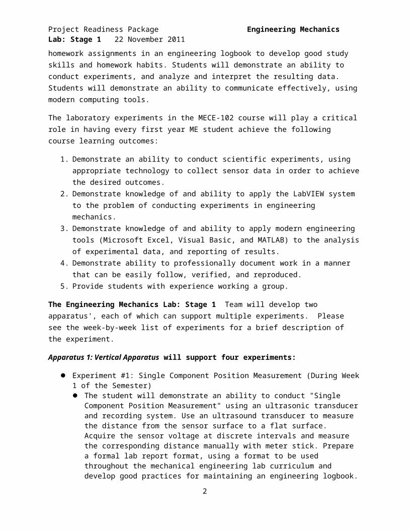
Project Readiness Package Engineering Mechanics Lab: Stage 1 22 November 2011
Project Summary: Engineering Mechanics Lab: Stage 1
The Mechanical Engineering Department at the Rochester Institute of Technology will be implementing a new course called "MECE-102 Engineering Mechanics Lab" into the core curriculum during the Fall semester of AY2013-14. The mission statement of the ME Lab Hardware family of projects is to design, develop and produce the lab hardware and corresponding experimental procedures for MECE-102. The experiments should elucidate several core mechanical engineering principles including: Newton’s Law of Gravity, Newton’s First Law, Newton’s Second Law, Newton’s Third Law and the Work Energy Theorem. All work produced by the multi-disciplinary senior design teams should be open source, encouraging the integration of these labs into the curriculum of other universities.
The course "MECE-102 Engineering Mechanics Lab" examines classical Newtonian mechanics from a calculus-based fundamental perspective with close coupling to integrated laboratory experiences. Topics include kinematics; Newton's laws of motion; work, energy, and power; systems of particles and linear momentum; circular motion and rotation; and oscillations and gravitation within the context of mechanical engineering, using mechanical engineering conventions and nomenclature. Each topic is reviewed in lecture, and then thoroughly studied in multiple accompanying laboratory sessions. Students conduct experiments using modern data acquisition technology; and analyze, interpret, and present the results using modern computer software. (This course will have a single Co-requisite: Math-181 Differential Calculus)
The goal of "MECE-102 Engineering Mechanics Lab" is to develop a strong foundation in Newtonian mechanics that students will build upon throughout their mechanical engineering curriculum. Using the student's prior exposure to high school physics, this course will extend student's knowledge of physics while integrating a formal understanding of the definition of derivatives and integrals. Students will learn the basics of good scientific laboratory and experimental techniques and develop the skills to present technical information in a formal engineering laboratory report. Students will complete homework assignments in an engineering logbook to develop good study skills and homework habits. Students will demonstrate an ability to conduct experiments, and analyze and interpret the resulting data. Students will demonstrate an ability to communicate effectively, using modern computing tools.
The laboratory experiments in the MECE-102 course will play a critical role in having every first year ME student achieve the following course learning outcomes:
1. Demonstrate an ability to conduct scientific experiments, using appropriate technology to collect sensor data in order to achieve the desired outcomes.
2. Demonstrate knowledge of and ability to apply the LabVIEW system to the problem of conducting experiments in engineering mechanics.
3. Demonstrate knowledge of and ability to apply modern engineering tools (Microsoft Excel, Visual Basic, and MATLAB) to the analysis of experimental data, and reporting of results.
4. Demonstrate ability to professionally document work in a manner that can be easily follow, verified, and reproduced.
5. Provide students with experience working a group.
1
Project Readiness Package Engineering Mechanics Lab: Stage 1 22 November 2011
The Engineering Mechanics Lab: Stage 1 Team will develop two apparatus', each of which can support multiple experiments. Please see the week-by-week list of experiments for a brief description of the experiment.
Apparatus 1: Vertical Apparatus will support four experiments:
Experiment #1: Single Component Position Measurement (During Week 1 of the Semester) The student will demonstrate an ability to conduct "Single Component Position
Measurement" using an ultrasonic transducer and recording system. Use an ultrasound transducer to measure the distance from the sensor surface to a flat surface. Acquire the sensor voltage at discrete intervals and measure the corresponding distance manually with meter stick. Prepare a formal lab report format, using a format to be used throughout the mechanical engineering lab curriculum and develop good practices for maintaining an engineering logbook.
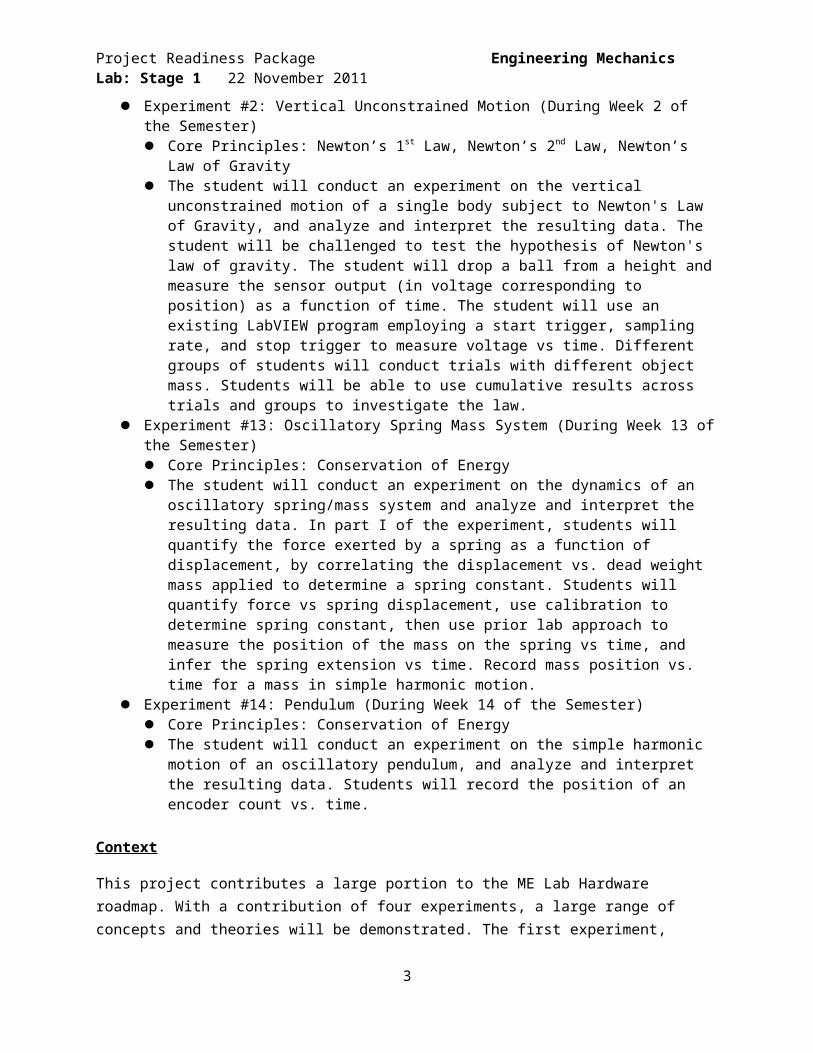
Experiment #2: Vertical Unconstrained Motion (During Week 2 of the Semester) Core Principles: Newton’s 1st Law, Newton’s 2nd Law, Newton’s Law of Gravity The student will conduct an experiment on the vertical unconstrained motion of a single
body subject to Newton's Law of Gravity, and analyze and interpret the resulting data. The student will be challenged to test the hypothesis of Newton's law of gravity. The student will drop a ball from a height and measure the sensor output (in voltage corresponding to position) as a function of time. The student will use an existing LabVIEW program employing a start trigger, sampling rate, and stop trigger to measure voltage vs time. Different groups of students will conduct trials with different object mass. Students will be able to use cumulative results across trials and groups to investigate the law.
Experiment #13: Oscillatory Spring Mass System (During Week 13 of the Semester) Core Principles: Conservation of Energy The student will conduct an experiment on the dynamics of an oscillatory spring/mass
system and analyze and interpret the resulting data. In part I of the experiment, students will quantify the force exerted by a spring as a function of displacement, by correlating the displacement vs. dead weight mass applied to determine a spring constant. Students will quantify force vs spring displacement, use calibration to determine spring constant, then use prior lab approach to measure the position of the mass on the spring vs time, and infer the spring extension vs time. Record mass position vs. time for a mass in simple harmonic motion.
Experiment #14: Pendulum (During Week 14 of the Semester) Core Principles: Conservation of Energy The student will conduct an experiment on the simple harmonic motion of an oscillatory
pendulum, and analyze and interpret the resulting data. Students will record the position of an encoder count vs. time.
Context
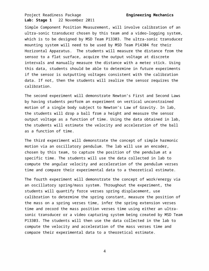
This project contributes a large portion to the ME Lab Hardware roadmap. With a contribution of four experiments, a large range of concepts and theories will be demonstrated. The first experiment, Simple Component Position Measurement, will involve calibration of an ultra-sonic transducer chosen by this team and a video-logging system, which is to be designed by MSD Team P13303. The ultra-sonic transducer mounting system will need to be used by MSD Team P14304 for their Horizontal Apparatus.
2
Project Readiness Package Engineering Mechanics Lab: Stage 1 22 November 2011
The students will measure the distance from the sensor to a flat surface, acquire the output voltage at discrete intervals and manually measure the distance with a meter stick. Using this data, students should be able to determine in future experiments if the sensor is outputting voltages consistent with the calibration data. If not, then the students will realize the sensor requires the calibration.
The second experiment will demonstrate Newton’s First and Second Laws by having students perform an experiment on vertical unconstrained motion of a single body subject to Newton’s Law of Gravity. In lab, the students will drop a ball from a height and measure the sensor output voltage as a function of time. Using the data obtained in lab, the students will estimate the velocity and acceleration of the ball as a function of time.
The third experiment will demonstrate the concept of simple harmonic motion via an oscillatory pendulum. The lab will use an encoder, chosen by this team, to capture the position of the pendulum at a specific time. The students will use the data collected in lab to compute the angular velocity and acceleration of the pendulum verses time and compare their experimental data to a theoretical estimate.
The fourth experiment will demonstrate the concept of work/energy via an oscillatory spring/mass system. Throughout the experiment, the students will quantify force verses spring displacement, use calibration to determine the spring constant, measure the position of the mass on a spring verses time, infer the spring extension verses time and record the mass position verses time using either an ultra-sonic transducer or a video capturing system being created by MSD Team P13303. The students will then use the data collected in the lab to compute the velocity and acceleration of the mass verses time and compare their experimental data to a theoretical estimate.
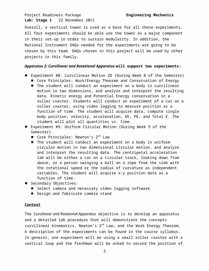
Overall, a vertical tower is used as a base for all these experiments. All four experiments should be able use the tower as a major component in their set-up in order to sustain modularity. In addition, the National Instrument DAQs needed for the experiments are going to be chosen by this team. DAQs chosen in this project will be used by other projects in this family.
Apparatus 2: Curvilinear and Rotational Apparatus will support two experiments:
Experiment #8: Curvilinear Motion 2D (During Week 8 of the Semester) Core Principles: Work/Energy Theorem and Conservation of Energy The student will conduct an experiment on a body in curvilinear motion in two dimensions, and
analyze and interpret the resulting data. Kinetic energy and Potential Energy conservation in a roller coaster. Students will conduct an experiment of a car on a roller coaster, using video logging to measure position as a function of time. The student will acquire data, compute single body position, velocity, acceleration, KE, PE, and Total E. The student will plot all quantities vs. time.
Experiment #9: Uniform Circular Motion (During Week 9 of the Semester) Core Principles: Newton’s 2nd Law The student will conduct an experiment on a body in uniform circular motion in two dimensional
circular motion, and analyze and interpret the resulting data. The centripetal acceleration lab will be either a car on a circular track, looking down from above, or a person swinging a ball on a
3
Project Readiness Package Engineering Mechanics Lab: Stage 1 22 November 2011
rope from the side with the rotational speed or the radius of curvature as independent variables. The student will acquire x-y position data as a function of time.
Secondary Objectives: Select camera and necessary video logging software Design and fabricate camera stand
Context
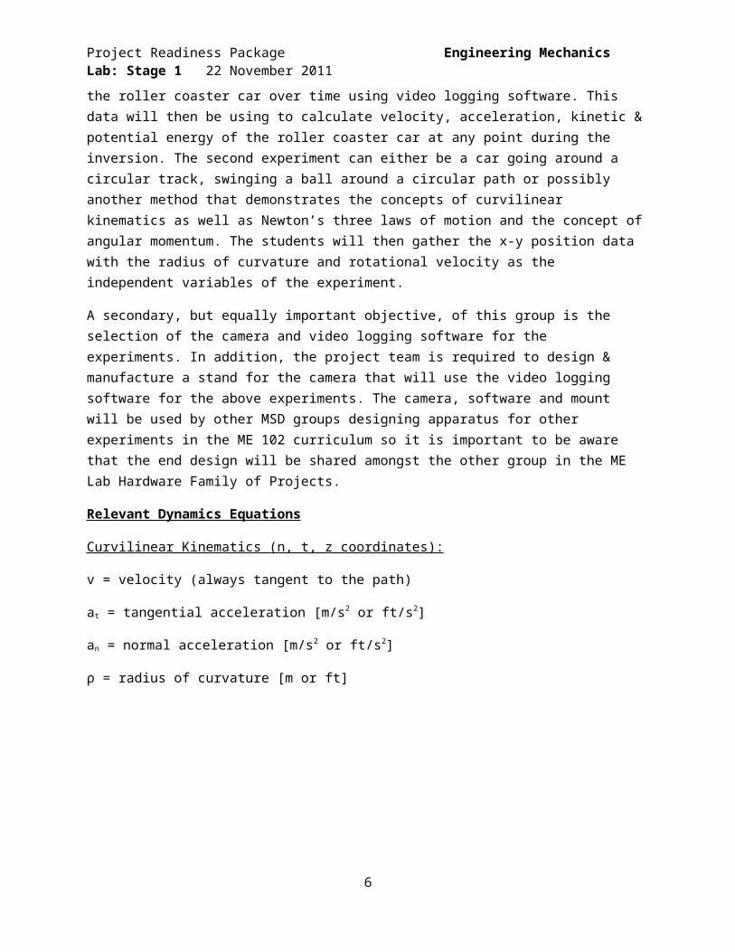
The Curvilinear and Rotational Apparatus objective is to develop an apparatus and a detailed lab procedure that will demonstrate the concepts curvilinear kinematics, Newton’s 2nd Law, and the Work Energy Theorem. A description of the experiments can be found in the course syllabus. In general, one experiment will be using a small roller coaster with a vertical loop and the freshman will be asked to record the position of the roller coaster car over time using video logging software. This data will then be using to calculate velocity, acceleration, kinetic & potential energy of the roller coaster car at any point during the inversion. The second experiment can either be a car going around a circular track, swinging a ball around a circular path or possibly another method that demonstrates the concepts of curvilinear kinematics as well as Newton’s three laws of motion and the concept of angular momentum. The students will then gather the x-y position data with the radius of curvature and rotational velocity as the independent variables of the experiment.
A secondary, but equally important objective, of this group is the selection of the camera and video logging software for the experiments. In addition, the project team is required to design & manufacture a stand for the camera that will use the video logging software for the above experiments. The camera, software and mount will be used by other MSD groups designing apparatus for other experiments in the ME 102 curriculum so it is important to be aware that the end design will be shared amongst the other group in the ME Lab Hardware Family of Projects.
Relevant Dynamics Equations
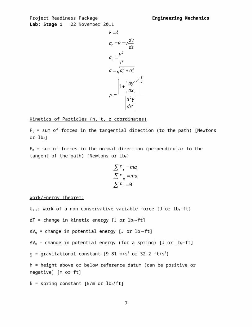
Curvilinear Kinematics (n, t, z coordinates):
v = velocity (always tangent to the path)
at = tangential acceleration [m/s2 or ft/s2]
an = normal acceleration [m/s2 or ft/s2]
ρ = radius of curvature [m or ft]
4
Project Readiness Package Engineering Mechanics Lab: Stage 1 22 November 2011
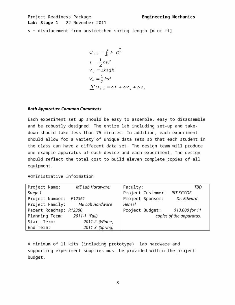
Kinetics of Particles (n, t, z coordinates)
Ft = sum of forces in the tangential direction (to the path) [Newtons or lb f]
Fn = sum of forces in the normal direction (perpendicular to the tangent of the path) [Newtons or lb f]
Work/Energy Theorem:
U1-2: Work of a non-conservative variable force [J or lbf-ft]
ΔT = change in kinetic energy [J or lbf-ft]
ΔVg = change in potential energy [J or lbf-ft]
ΔVe = change in potential energy (for a spring) [J or lbf-ft]
g = gravitational constant (9.81 m/s2 or 32.2 ft/s2)
h = height above or below reference datum (can be positive or negative) [m or ft]
k = spring constant [N/m or lbf/ft]
s = displacement from unstretched spring length [m or ft]
5
Project Readiness Package Engineering Mechanics Lab: Stage 1 22 November 2011
Both Apparatus: Common Comments
Each experiment set up should be easy to assemble, easy to disassemble and be robustly designed. The entire lab including set-up and take-down should take less than 75 minutes. In addition, each experiment should allow for a variety of unique data sets so that each student in the class can have a different data set. The design team will produce one example apparatus of each device and each experiment. The design should reflect the total cost to build eleven complete copies of all equipment.
Administrative Information
Project Name: ME Lab Hardware: Stage 1Project Number: P12361Project Family: ME Lab HardwareParent Roadmap: R12300Planning Term: 2011-1 (Fall)Start Term: 2011-2 (Winter)End Term: 2011-3 (Spring)
Faculty: TBDProject Customer: RIT KGCOEProject Sponsor: Dr. Edward HenselProject Budget: $13,000 for 11 copies of the
apparatus.
A minimum of 11 kits (including prototype) lab hardware and supporting experiment supplies must be provided within the project budget.
6
Project Readiness Package Engineering Mechanics Lab: Stage 1 22 November 2011
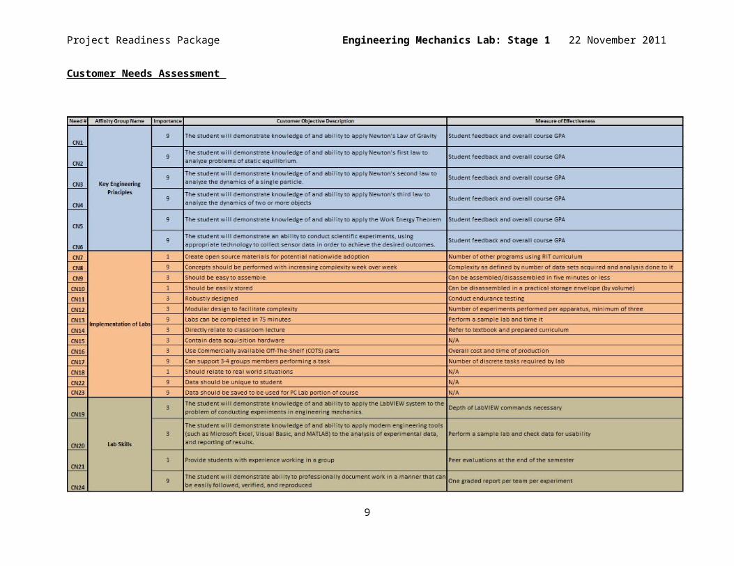
Customer Needs Assessment
7
Project Readiness Package Engineering Mechanics Lab: Stage 1 22 November 2011
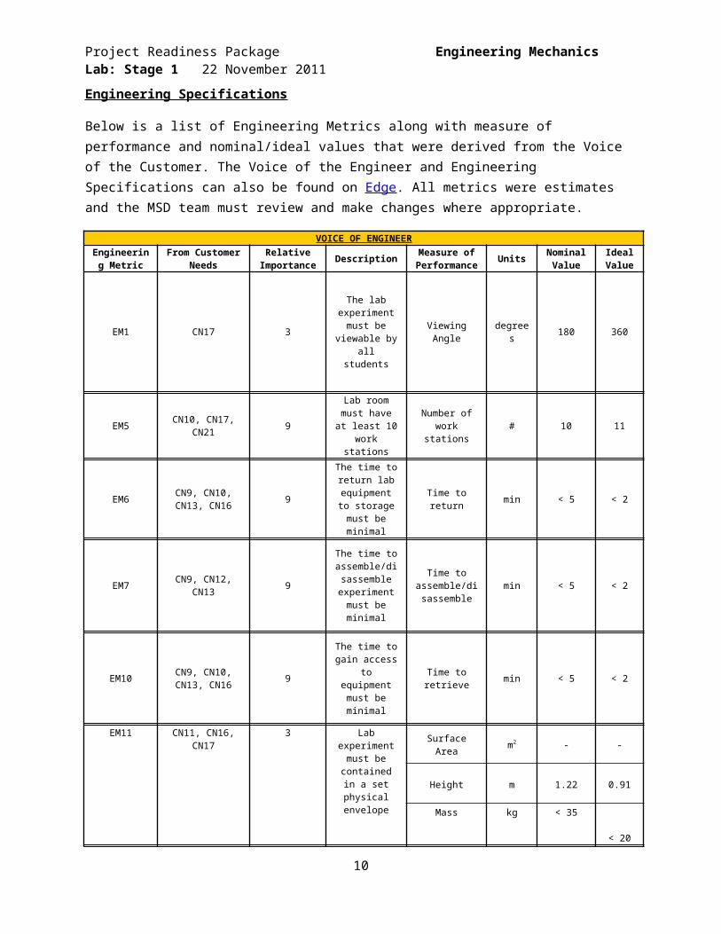
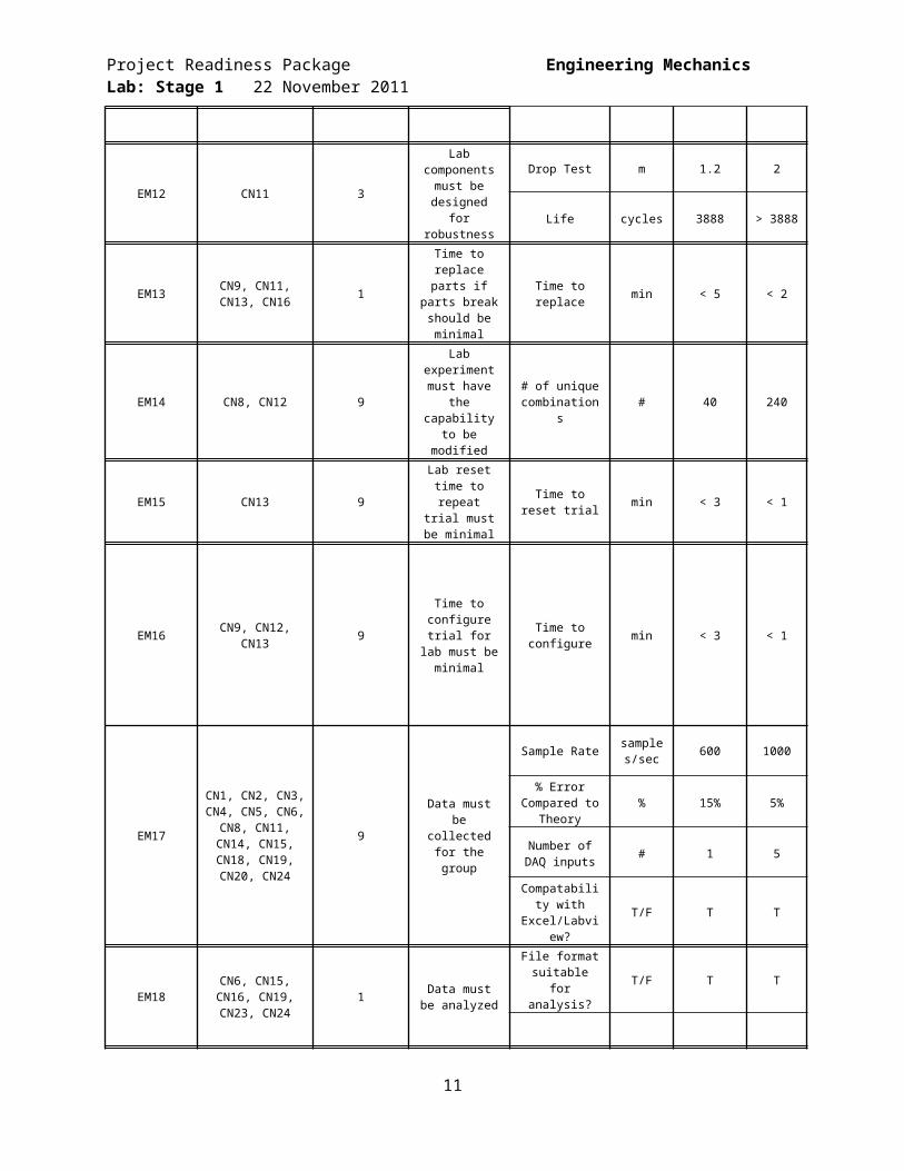
Engineering Specifications
Below is a list of Engineering Metrics along with measure of performance and nominal/ideal values that were derived from the Voice of the Customer. The Voice of the Engineer and Engineering Specifications can also be found on Edge. All metrics were estimates and the MSD team must review and make changes where appropriate.
VOICE OF ENGINEEREngineering
MetricFrom Customer
NeedsRelative
Importance Description Measure of Performance Units Nominal
ValueIdeal Value
EM1 CN17 3
The lab experiment
must be viewable by all
students
Viewing Angle degrees 180 360
EM5 CN10, CN17, CN21 9
Lab room must have at least 10
work stations
Number of work stations # 10 11
EM6 CN9, CN10, CN13, CN16 9
The time to return lab
equipment to storage must be
minimal
Time to return min < 5 < 2
EM7 CN9, CN12, CN13 9
The time to assemble/disas
semble experiment
must be minimal
Time to assemble/disas
semblemin < 5 < 2
EM10 CN9, CN10, CN13, CN16 9
The time to gain access to
equipment must be minimal
Time to retrieve min < 5 < 2
EM11 CN11, CN16, CN17 3
Lab experiment must be
contained in a set physical
envelope
Surface Area m2 - -
Height m 1.22 0.91
Mass kg < 35 < 20
EM12 CN11 3
Lab components
must be designed for robustness
Drop Test m 1.2 2
Life cycles 3888 > 3888
8
Project Readiness Package Engineering Mechanics Lab: Stage 1 22 November 2011
EM13 CN9, CN11, CN13, CN16 1
Time to replace parts if parts
break should be minimal
Time to replace min < 5 < 2
EM14 CN8, CN12 9
Lab experiment must have the capability to be
modified
# of unique combinations # 40 240
EM15 CN13 9
Lab reset time to repeat trial
must be minimal
Time to reset trial min < 3 < 1
EM16 CN9, CN12, CN13 9
Time to configure trial
for lab must be minimal
Time to configure min < 3 < 1
EM17
CN1, CN2, CN3, CN4, CN5, CN6,
CN8, CN11, CN14, CN15, CN18, CN19, CN20, CN24
9Data must be
collected for the group
Sample Rate samples/sec 600 1000
% Error Compared to
Theory% 15% 5%
Number of DAQ inputs # 1 5
Compatability with
Excel/Labview?T/F T T
EM18CN6, CN15, CN16, CN19, CN23, CN24
1 Data must be analyzed
File format suitable for analysis?
T/F T T
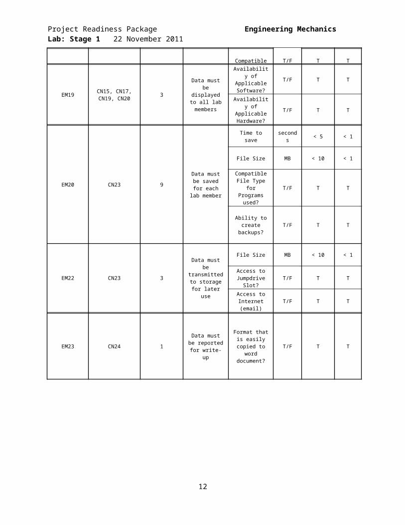
Compatible with DAQ? T/F T T
EM19 CN15, CN17, CN19, CN20 3
Data must be displayed to all lab members
Availability of Applicable Software?
T/F T T
Availability of Applicable Hardware?
T/F T T
EM20 CN23 9Data must be
saved for each lab member
Time to save seconds < 5 < 1
File Size MB < 10 < 1
Compatible File Type for
Programs used?
T/F T T
9
Project Readiness Package Engineering Mechanics Lab: Stage 1 22 November 2011
Ability to create backups? T/F T T
EM22 CN23 3
Data must be transmitted to
storage for later use
File Size MB < 10 < 1
Access to Jumpdrive Slot? T/F T T
Access to Internet (email) T/F T T
EM23 CN24 1Data must be reported for
write-up
Format that is easily copied to
word document?
T/F T T
10
Project Readiness Package Engineering Mechanics Lab: Stage 1 22 November 2011
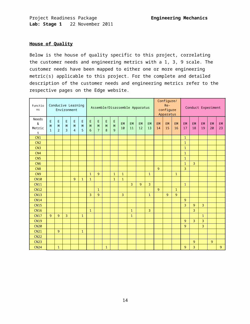
House of Quality
Below is the house of quality specific to this project, correlating the customer needs and engineering metrics with a 1, 3, 9 scale. The customer needs have been mapped to either one or more engineering metric(s) applicable to this project. For the complete and detailed description of the customer needs and engineering metrics refer to the respective pages on the Edge website.
Functions Conducive Learning Environment Assemble/Disassemble Apparatus
Configure/Re-configure Apparatus
Conduct Experiment
Needs & Metrics
EM1
EM2
EM3
EM4
EM5
EM6
EM7
EM8
EM9
EM10
EM11
EM12
EM13
EM14
EM15
EM16
EM17
EM18
EM19
EM20
EM23
CN1 1 CN2 1 CN3 1 CN4 1 CN5 1 CN6 1 3 CN8 9 3 CN9 1 9 1 1 1 1 CN10 9 1 1 1 1 CN11 3 9 3 1 CN12 1 9 1 CN13 3 9 3 1 9 9 CN14 9 CN15 3 9 3 CN16 1 1 3 3 CN17 9 9 3 1 1 1 CN19 9 3 3 CN20 9 3 CN21 9 1 CN22 CN23 9 9
CN24 1 1 9 3 9
11
Project Readiness Package Engineering Mechanics Lab: Stage 1 22 November 2011
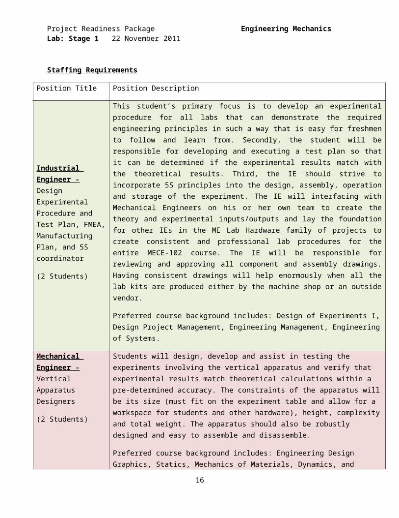
Staffing Requirements
Position Title Position Description
Industrial Engineer - Design Experimental Procedure and Test Plan, FMEA, Manufacturing Plan, and 5S coordinator
(2 Students)
This student’s primary focus is to develop an experimental procedure for all labs that can demonstrate the required engineering principles in such a way that is easy for freshmen to follow and learn from. Secondly, the student will be responsible for developing and executing a test plan so that it can be determined if the experimental results match with the theoretical results. Third, the IE should strive to incorporate 5S principles into the design, assembly, operation and storage of the experiment. The IE will interfacing with Mechanical Engineers on his or her own team to create the theory and experimental inputs/outputs and lay the foundation for other IEs in the ME Lab Hardware family of projects to create consistent and professional lab procedures for the entire MECE-102 course. The IE will be responsible for reviewing and approving all component and assembly drawings. Having consistent drawings will help enormously when all the lab kits are produced either by the machine shop or an outside vendor.
Preferred course background includes: Design of Experiments I, Design Project Management, Engineering Management, Engineering of Systems.
Mechanical Engineer - Vertical Apparatus Designers
(2 Students)
Students will design, develop and assist in testing the experiments involving the vertical apparatus and verify that experimental results match theoretical calculations within a pre-determined accuracy. The constraints of the apparatus will be its size (must fit on the experiment table and allow for a workspace for students and other hardware), height, complexity and total weight. The apparatus should also be robustly designed and easy to assemble and disassemble.
Preferred course background includes: Engineering Design Graphics, Statics, Mechanics of Materials, Dynamics, and Problem Solving with Computers, Design of Machine Elements and Measurement Instrument Controls. Familiarity with machine shop equipment is preferred.
Mechanical Engineer – Curvilinear and Rotational Apparatus Designers
(2 students)
Students will design, develop and assist in testing of the curvilinear and rotational apparatus and verify that experimental results match theoretical calculations within a pre-determined accuracy. The constraints of the apparatus will be its size (must fit on table and allow workspace of students and other hardware), height, complexity and total weight. The apparatus should also be robustly designed and easy to assemble and disassemble.
Students will also design and fabricate a stand for the video camera to be used in these and other experiments in the ME 102 course. Constraints for the stand are that it must be able to hold the camera for top-down and side perspective shots and take up a minimal area on
12

Project Readiness Package Engineering Mechanics Lab: Stage 1 22 November 2011
the table.
Preferred course background includes: Engineering Design Graphics, Statics, Mechanics of Materials, Dynamics, and Problem Solving with Computers, Design of Machine Elements and Measurement Instrument Controls. Familiarity with machine shop equipment would also be a huge plus. Finally, some experience with video logging either through coursework or internships would be useful.
Mechanical Engineer -Data and Video Logging System Engineer
(2 students)
Students will also choose an encoder, an ultra-sonic transducer, and a National Instruments DAQ for use in these experiments. Constraints for the encoder and ultra-sonic transducers are that it must be compatible with National Instrument DAQs. The constraint on the DAQs chosen is that the number of inputs for the DAQ must be able to accommodate the number of sensors being used. The number of outputs from the DAQ must be able to accommodate the number of independent variables being investigated in the experiment. STRONG Preference should be given to re-use DAQ hardware already available in the MIC lab.
Responsible for the selection of the video camera and video logging software for the above experiments and other experiments conducted in the ME 102 course. Student must work with other mechanical engineering students to ensure that the camera selected will fit in the designed stand.
Preferred background includes: experience with data acquisition and video logging either through coursework or internships. Courses that would be helpful include: System dynamics, Intro. to Controls, Robotics, MIC, Thermo-Fluids Lab I and II.
13
Project Readiness Package Engineering Mechanics Lab: Stage 1 22 November 2011
Project Constraints
Customer and Stakeholder Involvement
The team will be expected to carry out the vast majority of their interactions with the Team Guide. The Guide will meet with the team regularly to provide guidance, and help them prepare for and follow up on meetings with the sponsor. Because this project is a critical project to the ME department, the customer also desires a high level of engagement with the team.
The sponsor and primary customer (Dr. Hensel, ME Department Head) will be available for a series of meetings during the course of the project and will meet with a group of teams during the beginning of MSD1 to lay out common goals, objectives and philosophies for the sequence of projects. The sponsor requests that a single student point of contact be identified for coordinating all communications with the team.
It is anticipated that the sponsor will meet with the team (or multiple related teams) for 2 hour meetings approximately five or six times during MSD1. The sponsor recommends that the team schedule meetings (one team representative should please contact Jill Ehman, [email protected], to schedule all meetings) as follows:
o One hour during week 1o Two hours during week 3o Two hours during week 5 (Please also invite Dr. Robinson, Dr. Kempski, Mr. Landschoot,
Mr. Wellin, Mr. Hathaway, Mr. Kraynick, and Mr. Mannetti to this working session.)o Two hours during week 7o Four hour detailed design review during week 9 (Please also invite Dr. Robinson, Dr.
Kempski, Mr. Landschoot, Mr. Wellin, Mr. Hathaway, Mr. Kraynick, and Mr. Mannetti to this working session.)
o One hour during week 10 (Please invite Ms. Mitchell to this meeting) It is anticipated that the sponsor will meet with the team several times during MSD2. The
sponsor recommends that the team schedule meetings (one team representative should please contact Jill Ehman, [email protected], to schedule all meetings) as follows:
o One hour during week 1o Two hours during week 3o Two hours during week 5o Two hours during week 7o Two hours during week 9 (Please also invite Dr. Robinson, Dr. Kempski, Mr. Landschoot,
Mr. Wellin, Mr. Hathaway, Mr. Kraynick, and Mr. Mannetti to this working session.)
Regulatory Constraints
The design shall comply with all applicable RIT Policies and Procedures. The team is particularly asked to consider the KGCOE Honor Policy, and the RIT Academic Accommodations policy in their project.
Labs must conform to ABET criteria as expressed by the MECE-102 course syllabus.
14

Project Readiness Package Engineering Mechanics Lab: Stage 1 22 November 2011
Economic Constraints
The KGCOE ME Department has allocated $100,000 for the MECE-102 Laboratory. The total allotted budget for the ME Lab Hardware: Stage 1 is $13,000. Out of this budget, eleven lab kits (10 kits and one prototype) must be produced.
Each team will be required to keep track of all expenses incurred within their project and for the projected 10 copies.
Purchases for this roadmap will be run through the Mechanical Engineering Office. Each team must complete a standard MSD purchase requisition and have it approved by their guide. After guide approval, the purchasing agent for the team can work with Ms. Venessa Mitchell in the ME office to execute the purchase and obtain the materials and supplies.
Environmental Constraints
Material Safety Data Sheets (MSDS) are required for all materials, and must be displayed in the MECE-102 Laboratory. While no hazardous materials are anticipated in this project, we wish to use this laboratory environment as a teaching opportunity about MSDS.
All lab hardware will be stored and employed in the MECE-102 classroom/lab. (Currently the home of the MIC Lab).
Ethical Constraints
Every member of the team is expected to comply with Institute Policies, including the policy on RIT KGCOE academic honesty and the RIT policy on academic accommodations.
The resulting lab experiments and learning experience arising from these projects should provide an excellent introduction to the RIT KGCOE Honors Policy for all first year mechanical engineering students.
Manufacturability Constraints
Commercially available, Off-The-Shelf (COTS) components available from more than one vendor are preferred. Standard extrusions and components such as 80/20 are preferred.
It is preferable to use COTS sensors and components where practical, and manufacture only specialized parts in house.
Students should articulate the reasoning and logic behind tolerances and specifications on manufacturing dimensions and purchasing specifications.
It is expected that detailed manufacturing drawings and documentation will be generated by each team to facilitate a practical production schedule at the conclusion of the MSD project.
A minimum of 11 lab sets must be produced. Complete drawings and documentation must be provided to allow additional copies to be manufactured at a future date.
All dimensions must be expressed in both Customary US and Metric units on all drawings. All locally manufactured components should be manufacturable with in-house resources available at RIT Rochester and/or RIT Dubai.
15
Project Readiness Package Engineering Mechanics Lab: Stage 1 22 November 2011
Intellectual Property Constraints
All work to be completed by students in this track is expected to be released to the public domain. Students, faculty, staff and other participants in the project will be expected to release rights to their designs, documents, drawings, etc., to the public domain so that others may freely build upon the results and findings without constraint.
Students, faculty and staff associated with the project are encouraged to publish findings, data and results openly.
Students, faculty and staff associated with the project are expected to respect the intellectual property of others, including copyright and patent rights.
Sustainability Constraints
All raw materials and purchased materials, supplies and components used in the roadmap must have a clearly defined re-use, re-manufacturing or recycling plan.
This is intended to be a “zero landfill” project. This includes documents as well as project materials.
Each team in the project family is limited to no more than 150 pages of printed documentation during MSD 1 and MSD 2. Teams may use an unlimited amount of electronic documentation unless disk space becomes limited on the server.
Each team must prepare an MSD 2 poster not included in the paper constraint above. Each team must prepare an MSD 2 technical paper not included in the paper constraint above.
Time Constraints
Lab equipment must be ready for implementation (including fabrication of one prototype lab kit) by May of 2012.
Ten additional copies of the Lab equipment must be manufactured by Mechanical Engineering professional staff during summer 2012, and ready for the start of class in September 2012. These experiments will be piloted in the PSWC and MIC class during AY2012-13, prior to full production in AY2013-14.
Labs must be set up, data collected and broken down in less than 75 minutes.
16
Project Readiness Package Engineering Mechanics Lab: Stage 1 22 November 2011
Required Faculty/Environment/Equipment
Category Source Description Resource Available
(Y/N)Faculty RIT ME/EE/IE/CE
DepartmentsFaculty that specialize in dynamics for any ME
questions. Specific faculty to be engaged include: Dr. Robinson, Dr. Kempski, Mr. Landschoot, and Mr. Wellin.
Y
Staff RIT ME Dept. Professional staff will be expected to fabricate and maintain additional copies of this hardware in the
future. They must be actively engaged in the project from the beginning. Specific staff to be engaged
include: Mr. Hathaway, Mr. Kraynick, and Mr. Mannetti for all shop related activities. Ms. Mitchell should be
engaged for all financial activities. When appropriate, the team is requested to engage an NTID interpreter
and an NTID captionist.
Y
Environment RIT Senior Design Space
A designated place to work and store all materials necessary for project completion and organization
Y
Equipment RIT ME Department
Parts can be created using the machine shop. Because of the nature of this project, the department
encourages active participation of professional staff in the prototyping phase, alongside the students.
Y
Materials Online and local suppliers
Metal stock, sheet metal, fasteners, wires, video logging software, camera, etc.
Team to Acquire
Materials Online and local suppliers
Encoders, Transducers, DAQs and COTS components needed for creation of labs
Team to Acquire
17