Embed Size (px)
Citation preview
Abstract
Brief SummaryLeuko – goalTop level designFinal Results
The long term goal of this project is to design and develop a system allowing the customer, who has leukodystrophy, to control an external device and play electronic games. The success of this meaningful task would add independence and have a huge positive impact on the quality of life of the customer.
Introduction
Leukodystrophy and challenges – JackLeukodystrophy is a class of degenerative genetic conditions in which the myelin sheaths surrounding nerve fibers in the body either do not develop properly or degrade over time. The resulting imperfect insulation between nerves makes motor control very difficult and imprecise, as signals do not always reach their intended targets. As a result, people living with leukodystrophy or similar conditions are often dependent on caretakers to help them with most physical tasks. This level of dependence can sometimes prove more difficult for the affected person as well as their family, especially if others are not always available to help. Therefore, any means of enhancing their independence by allowing them to perform tasks without assistance may have a significant impact on quality of life.
Tobii/Vanguard (Pros/Cons) – JackMany devices have been developed which assist those with similar conditions with everyday tasks such as communicating or accessing information. One such device, Prentke Romich Company's Vanguard 2, uses a large touch interface to allow the user to express himself by selecting various icons. While sometimes effective, this device can prove frustrating when its icons are too small for the user to distinguish between when pressing them - conditions such as leukodystrophy make this level of fine motor control difficult. An alternative technology is eye-gaze tracking, which uses the orientation of the user's eyes to determine where on a display they are looking. The Tobii PCEye(tm) system uses this technology to allow the user to express themself using a similar icon-based interface; the eyes are generally much more precise than limb movements, making this system easier to use. However, this system is rather expensive and is often only available through [grants]. Additionally, it does not exercise the user's motor control skills.
Goal/Objective/Design
Process
Condensed Needs/Specs – Jack and DingIterative Capability Testing – Jack and Ding
Conclusions/decisions
Top level design/layout – full detailMechanical –Alex/CoryElectrical - DanSoftware – Jack/Ding
Needs and Specs
Before the initial brainstorming and planning process can begin, the customer needs and specifications must be completely analyzed and understood. The primary need of the customer is to be able to control an electronic gaming device with little or no assistance. The device needs to be able to use physical motion from the customer to produce an input. Because of how quickly new technologies are produced, the device must be able to adapt to future devices that may be owned by the customer. Games are required to be capable of being activated by the customer, and the device must support multiplayer gaming options. Other customer needs include convenience (set-up time and portability) and safety (allows normal motion).
To determine whether or not the customer needs are being satisfied, certain specifications must be met. The set-up and break-down of the device must each take one individual less than a minute and a half to accomplish. The device must also not limit our customers’ normal range of motion. Therefore, the arms must still be able to move 180 degrees and legs must be able to stretch out to 90 degrees. The controller must be able to support about 20 pounds. Other specifications that must be met include temperature range that the user feels, controller weight and size, number of sharp edges, and length of battery life.
A test procedure document was produced in order to make sure that each specification was met by the final device. The test procedure included specific instructions on how to test each specification. Tolerances were included in the document in order to quickly verify whether or not the device met the specifications according to the test performed.
Iterative Capability Testing
Five testing sessions have been conducted to allow the customer to try out various designs. By working closely with the customer, the team was able to understand his specific capabilities and create a system that makes use of his motions effectively. An initial session was used to observe the customer’s motion capabilities and motor control skills, in order to determine which motions were most comfortable and most consistent.
After determining the customer’s capabilities, a series of prototype control schemes were designed. These prototypes were then evaluated by the customer and his family, giving the team valuable feedback.
The first testing session used a wooden slider prototype which controlled either velocity or absolute position of a mouse cursor on a projector screen. The accuracy the customer was able to achieve with both methods was encouraging; however, the prototype was prone to binding, and some assistance was required. The slider also proved difficult to grasp. For these reasons, the slider was rejected as a control scheme. On the other hand, the testing was informative and several key factors were observed during the testing. The user mainly used the palm or wrist to move the slider rig and had

better control and more strength moving it inward and outward when using his left hand and side to side when using the right hand.
The second testing session used a padded lever to control the velocity of a mouse cursor. Changes and adjustments were made to the system to better accommodate the user's capabilities based on the observations from the first testing session. As a result, the testing was effective and the user was able to control the lever with minor to no assistance and move the mouse cursor to a certain position relatively easily. Therefore, the idea of lever control was adopted and design proceeded with this input mechanism.
Mechanical
Mechanical design of the control platform began immediately after finalizing the methods for obtaining input from the customer. The most obvious function of the control platform is to provide the customer with oversized joysticks at the hands and IR sensors at the feet. The platform also serves as the storage location for all electrical components while providing access to any adjustment and connectivity controls. A second mechanical system locates the tablet for use by the customer. Special care was taken to insure that the final design was ergonomic for both the customer and his caretakers.
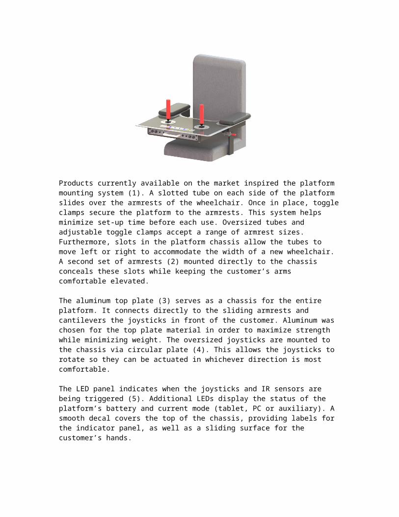
The largest mechanical challenge was designing robust and ergonomic components that could all be fabricated within the time constraint. In order to overcome this challenge, 3D modeling was used extensively from the start. In order to keep the device portable, it was determined that it should mount directly to the customer’s wheelchair. Furthermore, this design required that any mounting system be adjustable should the customer purchase a new wheel chair. To accommodate this requirement, the customer’s current wheelchair was modeled, and the design was completed from the mounting system outward. The figure below is a rendered image of the final 3D drawing. The paragraphs following summarize the design.
Products currently available on the market inspired the platform mounting system (1). A slotted tube on each side of the platform slides over the armrests of the wheelchair. Once in place, toggle clamps secure the platform to the armrests. This system helps minimize set-up time before each use. Oversized tubes and adjustable toggle clamps
accept a range of armrest sizes. Furthermore, slots in the platform chassis allow the tubes to move left or right to accommodate the width of a new wheelchair. A second set of armrests (2) mounted directly to the chassis conceals these slots while keeping the customer’s arms comfortable elevated.
The aluminum top plate (3) serves as a chassis for the entire platform. It connects directly to the sliding armrests and cantilevers the joysticks in front of the customer. Aluminum was chosen for the top plate material in order to maximize strength while minimizing weight. The oversized joysticks are mounted to the chassis via circular plate (4). This allows the joysticks to rotate so they can be actuated in whichever direction is most comfortable.
The LED panel indicates when the joysticks and IR sensors are being triggered (5). Additional LEDs display the status of the platform’s battery and current mode (tablet, PC or auxiliary). A smooth decal covers the top of the chassis, providing labels for the indicator panel, as well as a sliding surface for the customer’s hands.
The electrical enclosure mounted to the bottom of the chassis houses all electrical components and provides a panel interface for the customer’s caretakers (6). The handle at the center of the panel can be used during transport and set-up, but also serves as a mounting location for the tablet bracket. The USB connection directly left communicates with the tablet or PC. The button directly right toggles the platform mode. Outside of the USB plug and mode button are the connections for the IR sensors. Furthest out are tuning knobs that adjust the speed of mouse motion, clicking sensitivity and clicking delay.
The IR sensors are located at the customer’s feet using 3D printed plates (7). Elastic banding runs through the plates and around the customer’s feet, creating minimum set-up time. A shroud on each plate protects the IR sensors from harm.
A modular design was adopted for the tablet mount so that it can be used separate from the control platform (8). The actual tablet is fitted with a robust “Otterbox” case that is secured in a cradle by elastic at each corner. The cradle connects to a sturdy flex arm that can locate the tablet in any orientation. At the end of the flex arm is a universal mount that can be fixed to a range of circular or rectangular surfaces.
Electrical
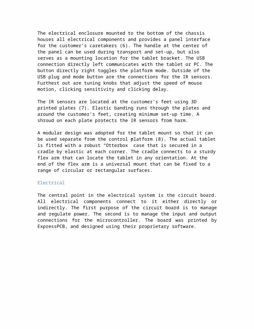
The central point in the electrical system is the circuit board. All electrical components connect to it either directly or indirectly. The first purpose of the circuit board is to manage and regulate power. The second is to manage the input and output connections for the microcontroller. The board was printed by ExpressPCB, and designed using their proprietary software.
The power section of the circuit is comprised of two sections. The first section takes in a 12V DC supply voltage from an external AC/DC converter through a jack mounted on the left side of the enclosure. The 12V DC source is then internally regulated down to 5V using a switching regulator. A switching regulator was chosen because it is power efficient and produces little heat. A relay then connects the regulated 5V output directly to the 5V line of the circuit board and microcontroller.
The second power section is the battery and charging hardware. When the 12V DC source is present, a normally closed relay is turned off isolating the battery from the operating circuitry. Once the battery is isolated, a relay provides power to the battery charger. The battery is then charged until full. This is indicated by the charger status LED. The forward voltage of the LED is referenced by the microcontroller to monitor charging status. Once fully charged the charger relay is switched off, completely isolating the battery. When the 12V DC source is not present, the system is run on battery power. The battery and charger are both contained in the enclosure. All power is routed to an ON/OFF switch located adjacent to the external 12V DC supply jack.
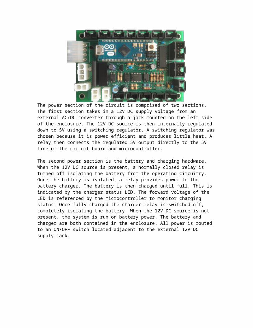
The second purpose of the circuit board is to manage all incoming and outgoing signals to and from the microcontroller. On the board, this involves routing signals and power to the many header pin jacks used to connect the peripherals.
Mounted on the front panel is a mode button, USB jack, two jacks for the IR foot sensors, and four tuning potentiometers. The tuning potentiometers allow for software
parameters to be tuned externally by the user. The IR sensors are mounted on platforms attached to the operators feet. A cable with a Binder 709 series connector connects to a mating panel mounted jack. The Binder 709 series connectors were chosen due to their quick connect ability and durability. The USB jack connects the microcontroller to a tablet or PC. The mode button is used to switch between the three possible modes.
Mounted on the top surface of the chassis are the joysticks and indicator LEDs. The joystick switches are internally wired and routed to the circuit board. Some LEDs are powered by hardware, and others by an LED driver on the circuit board. The indicator LEDs for the joysticks are powered directly by the joystick signals. The low battery LED is controlled by a sub-circuit that compares the battery voltage to a preset voltage using a comparator and a Zener diode. The output of the comparator switches on a relay that powers the low battery LED off of the battery. The mode, IR sensor, power, and charging LEDs are all controlled by the LED driver.
Software
A Pugh diagram was created to determine the most applicable microcontroller to be used for this project. Key criteria such as cost, east of use, size and weight, availability of resources, reliability, adaptability, and number of I/O pins were investigated for microcontroller concept selection. The Arduino Micro was compared with the Parallax BASIC Stamp MCU, the PIC MCU, the Cypress EZ-USB Micro, and the TI MSP 430. Based on the scorings for each of the microcontrollers, the Arduino Micro had the highest consolidated score and was hence chosen.
The Arduino Micro is an USB-native 8 bit microcontroller with 20 I/O pins, 32k of flash, and 2.5k of RAM. The microcontroller runs at 5V logic and has a 3.3V regulator. Moreover, the board can be programmed directly via the Micro-USB connector. The open-source Arduino environment makes it easy to write code and upload it to the Arduino board. Also, it is adaptable and runs on Windows, Mac OS X, and Linux.
Image of how Arduino Micro interfaces with Samsung Galaxy Tab
The Arduino Micro is acting as a Human Interface Device that interacts directly with and takes input from users. It is connected to the Samsung Galaxy Tab via a Micro-USB and a tablet adapter. The tablet adapter turns the Samsung Galaxy Tab into an USB host, allowing the connection of compatible USB accessory devices such as mouse and keyboard to the tablet. Moreover, The Arduino Microcontroller is the heart of the control system. It filters and processes input data from both joysticks and infrared sensors to determine the user's intentions, it then uses the Human Interface Device protocol to communicate these intentions as actions on an Android device, including moving, clicking, and dragging a mouse cursor.
Image of software subsystem flowchart
The MAX6968 LED driver is used by the Arudino Micro to indicate system state information such as joystick movements and foot sensor/mouse click event to the user. The Arduino Micro interfaces with LED driver through the Serial Peripheral Interface (SPI). The input data that the Arduino Micro receives from the user is transferred to the LED driver through the MOSI of the SPI. Moreover, the Arduino Micro receives an analog input from the adjustable potentiometer and the analog input is used for controlling the movement speed of the mouse cursor.
The Arduino Micro receives user input from joysticks as digital data or switch state. The switch states are transferred over the SPI bus (MOSI) and the corresponding LEDs are turned on or off signaling the mouse movements. Moreover, based on the joystick movements and user-controlled scaling factor, the digital data is translated into 2D motion. The mouse is moved based on the translated data using HID commands. The current cursor position also gets updated based on the cursor movements. If the mouse cursor is at the edge of the screen, the cursor is wrapped around the screen.
The Arduino Micro receives user input from IR Sensors as analog data. In order to filter the analog data to reduce noise, a data array with a capacity of 9 is used to store analog sensor values and bubble sort is used to sort the data array and to determine the median of the data array. The mouse click state is determined based on the median value. If a spike or change in distance is detected, the mouse is clicked using an HID command. Also, the mouse click states are then transferred over the SPI bus (MOSI) and the corresponding LEDs are turned on or off signaling mouse clicks. Furthermore, a timer is set for when the mouse can be clicked again.
Results
A test procedure document was produced in order to validate that each specification was met by the final controller device. The procedure included detailed instructions on how to test each specification, as well as the target value and tolerances for each test in order to quickly verify whether or not the device met the specification. Based on the testing performed, our device met every specification. The set-up and break-down time each took less than one minute to perform. Pull tests were accomplished to test the controller attachment strength to the wheelchair. While the controller was completed secured to the wheelchair, a Berkley FS50 force gage was used to pull out horizontally and then to pull down vertically on the mount handle at the front of the controller. The horizontal and vertical pull tests issued results of 15.5 pounds and 17.1 pounds, respectively. Both of these values fall within the tolerances. The force gage was also used to test the attachment strength of the toggle clamps. The test yielded a successful result of 2.1 pounds. The device did not restrain the user from having an allowable range of motion of 180 degrees with each of his arms, or 90 degrees with each of his legs. A temperature range test was implemented in order to confirm that the controller would not radiate heat that would be uncomfortable for the user. Results were successful. The user was able to play games on the control device with more than one user, producing a positive result for testing user interface. Other successful test results included controller size and weight specifications, number of sharp edges, and battery life.
Lessons LearnedPics and brief description of final productUser Manual
Based on the most recent testing sessions, the joysticks and IR sensors were able to accurately detect movement from the user and the customer was able to use the control system to play a game on the Samsung Galaxy Tab 2. Most importantly, they were able to choose, launch, and play a game without any assistance, which demonstrates the added independence the system offers. Although it took some time for the customer to become familiar with how the system works, he was able to pick it up quickly and enjoy a variety of different games. Moreover, the system is designed to be easily maintainable and highly extensible, making it relatively simple to improve the system or add new functionality.
Lessons learned It is very important to keep in close touch with the customers and understand and collect
adequate data with respect to customer needs and engineering specifications. More time spent ahead of time on developing plans and performing analysis would save
a lot of effort in problem solving afterwards. Careful planning on the costs of every part and ordering parts as early as possible due
to lead time and taking into account time for manufacturing.
More exposure to full development from planning to completion of a project Gained practical experience working on a real product that has an end user (customer) Learned about requirement gathering and risk management Learned about human interface devices Learned how to program a microcontroller and made use of libraries Familiar with EDGE and subversion
Conclusions
EvaluationWhat would we change/do againFuture work?
References
Links to:LeukoTobiiVanguard