Embed Size (px)
Citation preview

Edge Finishing of Large Turbine Casings UsingDe�ned Multiedge And Abrasive Tools In AutomatedCellsAdrian Rodríguez
University of the Basque Country (UPV/EHU)Mikel González ( [email protected] )
University of the Basque Country (UPV/EHU) https://orcid.org/0000-0003-2257-442XOctavio Pereira
University of the Basque Country (UPV/EHU)Luis Norberto López de Lacalle
University of the Basque Country (UPV/EHU)Mikel Esparta
University of the Basque Country (UPV/EHU)
Research Article
Keywords: Finishing, deburring, automation, aeronautical, Inconel, engine components, robotics
Posted Date: April 26th, 2021
DOI: https://doi.org/10.21203/rs.3.rs-417726/v1
License: This work is licensed under a Creative Commons Attribution 4.0 International License. Read Full License

Edge finishing of large turbine casings using defined multi-
edge and abrasive tools in automated cells
Adrian Rodríguez1, Mikel González1, Octavio Pereira1, L. Norberto López de Lacalle1, Mikel Esparta2
1 CFAA - Aeronautics Advanced Manufacturing Centre, University of the Basque Country (UPV/EHU),
Biscay Science and Technology Park, Ed. 202, 48170, Zamudio, Spain
2 ITP Aero S.A., Parque Tecnológico n° 300, Zamudio, 48170, Spain
Corresponding author: Mikel González
+34 94 601 8479
Abstract
Automate finishing processes is a global challenge in several industrial sectors. Concretely,
when dealing with aero-engine components, only simple finishing processes were automated
nowadays. Most of the high-added value components manufactured are finished hand working,
using deburring and polishing manual techniques. The driver of the proposed work is to achieve
the necessary knowledge to introduce in a production line a complete and finishing process for
automated robotic deburring applications with low machinability materials (Inconel 718 in the
case of study) on aero-engine casings with complex geometries: extruded casting bosses,
internal features, etc. For this purpose, a three-step methodology is presented and analysed,
providing a feasible workflow combining multi-edge solid tools and flexible abrasive tools to
automate finishing operations taking account all the process drawbacks and peculiarities.
Results show that using the correct techniques, processes and parameters, an automated
finishing process that reduces operating time can be implemented in production lines.
Keywords
Finishing, deburring, automation, aeronautical, Inconel, engine components, robotics
Acknowledgements The authors wish to acknowledge the support received from the Basque
Government.
DECLARATIONS
Funding No funding was received to assist with the preparation of this manuscript.
Availability of data and material The data and material in this paper are original, available,
and objective.
Code availability Not applicable.
Conflicts of interest and competing interests Not applicable.
Ethics approval Not applicable.
Consent to participate All the authors consent to participate in this work.
Consent for publication All the authors in this work have consented to publish this manuscript.

1. Introduction
Manufactured components with functional surfaces usually require high surface
finishes [1-2]. In many sectors, manufacturing processes such as milling, turning or
hole making were commonly used. These processes generate undesirable surface
quality caused by burrs, scratches, or insufficient finish. Traditionally, many finishing
processes were handmade, mainly when dealing with complex geometries or high
added value parts. Nevertheless, in the last years, there is a clear tendency of trying to
automate as far as possible this kind of processes [3-4].
Deburring processes deal with the elimination of non-predictable material. Burrs
generated during machining processes are difficult to characterize in a repeatable way
[5]. This is, there are many different kinds of possible burrs generated and in some
case their formation is aleatory. To define and develop techniques to eliminate burrs
automatically, the first step is to be able to characterize the burr type and compare
different part-references and batches in order to assure repeatability in the process of
burr generation.
In 2003, a complete deburring and edge finishing handbook was published by Gillespie
[6]. This work contains information regarding the commonly used deburring and
polishing processes in manufacturing industry. Moreover, a complete classification of
burr types was presented, characterizing burr in terms of their formation. In this line,
the author differences six different types of burr formation: lateral creep due to
compression, material bending, detachment from the chip (tear), redeposition of
material, incomplete cutting, material creep due to breaks [7]. On the other hand, some
other burr classifications were used in the last decades, such as the one proposed by
Ramachandran et al. [8] which is based on four different families of burr mechanism
formation (Poisson burr, roll-over, tear and separation without cutting). Other authors
analyze the process of burr formation using material resistance criteria [9] or
geometrical criteria, such as Schäfer [10] understanding the burr formation process
using five geometrical parameters. The problem is that the measurements of the burr
root thickness, the burr root radius and the burr thickness are difficult to perform non-
destructively. Finally, the ISO 13715 [11] proposes a measure of burr height from the
theoretical exit edge of the workpiece to the top of the burr.
Integration of robots in machining processes combines the advantages of the flexibility
of manual operations with the repeatability of machine tools [12]. In the last years,
deburring and polishing using automated robotic cells has reached great importance as
super-finishing technology. Robot manufacturers present new specialized models for

this kind of purposes, and new cell manufacturers provide solutions in this line [13], but
not many aeronautical applications are shown industrialized, due to the high
requirements of precision and repeatability. Furthermore, materials found in aero
engine components present very low machinability, while most studies focus on
applications with soft materials such as aluminium [14]. Materials such as Inconel 718
present major difficulties when it comes to machining, due to its excellent mechanical
properties at high temperatures. Forces and temperatures in the cutting zone for this
material are extremely high due to the high shear stress and low thermal conductivity
[15]. On account of this, research that includes Inconel 718 among working materials
for robotic deburring processes is very scarce. This kind of high added-value
components, such as casings or radial structures, involve multiple manual processes
within the last phase of the manufacturing process: the hand finishing operations. Due
to a lack of technological development in the market that could fulfill the necessity in
terms of quality requirements/standards, in certain stages of the production processes,
hand finishing remains necessary to guarantee the quality of a finished aero-engine
part.
In this work, development was focused on intermediate module casings, LPT (Low
Pressure Turbine) casings and radial structures, being the extruded bosses of these
components the main case study. The amount of manual effort regarding these
features, could represent the more than the half of the complete deburring process of a
component. Regarding the architecture of a LPT casing (slim part), a radial structure
(mechanized-welded part), or an intermediate module casing (casting-forging,
mechanized-welded part), the same problem could be found: variability in feature edge
location, geometrical variability of the burr generated in previous milling/turning steps,
and final edge finishing control within defined limits.
Technologically speaking, some important developments were shown in scientific
international papers to deal with the positioning problem. Automated deburring
processes normally used pneumatic tools to obtain axial and radial tool compensation,
as summarized in [16]. Some advances have been developed in this line. As an
example, Ziliani et al. [17] proposes a mechatronic methodology for the active control
of automated deburring of components with unknown geometry. In [18], Kim et al.
proposes a new control process for deburring using pneumatic tools, modifying air flow
and pressure in order to deal with the discontinuities between the part and the tool. In
[19], Chen et al. propose a geometrical system compensating the toolpath in real time.
Path compensation is a widespread practice in casting deburring operations. Initially,
these corrections were carried out by multi-point contact teaching methods along the

parts [20]. Nowadays, many industrial application techniques use artificial automation
methods to achieve highly accurate alignments [21-23]. Novel artificial vision systems
are implemented in this kind of processes to measure the geometrical variations of the
parts and automatically adapt the position, as presented by Princely [24]. Through a 3D
scan of the part, stereolithographic (STL) model is generated, which is then used to
adapt the nominal trajectory to the real part geometry [25]. However, artificial vision
techniques have an associated positioning error which, although smaller than the effect
of the dimensional variations of the part, must be taken into account. A possible
solution combines vision positioning techniques with passive force-compensated tools
(easier to implement and cheaper than active force systems) and establishes the
process conditions in operations with low machinability materials, and no
bibliographical background have been found in this line.
Thus, this work presents a detailed methodology for this purpose, including part
positioning, features identification, edge cutting using conventional cutting tools and
radii polishing using abrasive tools. The scope of this article is limited to defining the
steps on which the process is based and analysing their feasibility so that they may be
developed in the future in a fully automated way. Having performed several tests and
iterations, early results show that a feasible methodology is possible combining
different technologies. Concretely, to present real process data to support this
methodology, three working lines are presented in this work: i) geometrical inspection
and analysis to identify the working features, ii) deburring tests using force-
compensated carbide tools in order to eliminate machining burrs and generate a
chamfer, and iii) polishing using abrasive tools to generate small radii to obtain a
smooth edge geometry under requirements. Tests and results are supported and
checked with surface measurements, including roughness, edge geometry and visual
inspection. These advances define a methodology providing a clear workflow
identifying the key aspects to achieve successfully a final component fitting the
requirements.
2. Industrial challenge and requirements
The selected component to illustrate this work is the so-called outer case of a MTF
(Mid Turbine Frame) of an aeronautical engine, but some other engine components
present the same requirements and difficulties. In this work, a non-confidential design
was used as test part in order to provide a platform for the implementation of all the
advances developed. In some part numbers, the outer case presents complex features

called bosses. These bosses are commonly manufactured via casting process,
obtaining a hybrid component formed by a casting ring assembled in an Inconel 718
forged casing, just as shown in Fig.1. In a common process, after face-milling of boss
shape features a high volume of manual deburring operations is necessary (more than
15 hours in some cases). The aim of this work is to define a methodology in order to
develop capability of doing automatic deburring tasks by on-machine adaptive
deburring.
Component 1: Forge as raw material
Component 2: Casting as raw material
Bosses
WeldingComponent 1
Component 2
Fig. 1 Outer case component description
Boss shape features are the most critical and complex features in terms of deburring
and finishing. These are extruded geometries obtaining via casting process. This
manufacturing process provides a component with not so tight tolerances (±2 mm are
commonly obtained values on these kind of components).
Comparing nominal geometry between real manufactured geometry, deviations on
bosses can be of three different nature, these are: misalignments, overstocks or a
combination of both. These deviations are the key to identify the correct edge location
to perform the deburring and edge cutting process following the correct toolpath. Edge
finishing shall be contained within a defined and controlled area, every edge shall be
deburred (break sharp edge) within 0.1-0.4 mm, as shown in Fig.2. For this purpose, a
methodology based on three steps is presented in this work: i) edge location and
positioning, ii) deburring and edge cutting, iii) polishing sharp edges.

0.4 mm
0.1 mmBoss shape
feature
Fig. 2 Edge location problems on boss shape features and edge finishing requirements
3. Proposed methodology
Obtain a feasible and automated finishing process for high-added value engine
components is the driver of the proposed methodology. Some of these components are
manufactured from casting rings, so processes developer must deal with notable
variability regarding edge location and burr geometry and nature. A detailed step-by-
step planning is presented in this paper, but in this section a general vision of the
methodology is presented, as shown in Figure 3. This methodology is based on three
main steps:
1. 3D scanning using non-contact geometrical measurement technologies. The idea
is to obtain a cloud point of the real geometry to generate toolpaths that better
adapt to part deviations. For edge detection, positioning is compared with the
nominal geometry. Thus, real data of the edge location are obtained, improving
positioning and ensuring uniform contact of cutting tool along workpiece.
2. Once the feature location is known, burrs removal process should be performed.
Due to the width variability of burr types and sizes, different tools and cutting
conditions should be studied. Multi-edge carbide tools allow complete removal of
burrs by adjusting compensation force to the size of burrs.
3. Within the final finishing step not only the primary edges should be controlled.
Depending on the requirements of the part, also the secondary edge geometries
are defined and should be controlled. Thus, an abrasive tool should be used in
order to finish and polish sharp edges, obtaining the required radii. For this
purpose, the use of force-compensated abrasive brushes is proposed.

SCANNING & PROCESSINGVIRTUAL ENVIRONMENT &
TOOLPATH GENERATION
DEBURRING &
EDGE-CUTTING
SECONDARY
EDGE POLISHINGFINAL COMPONENT
& INSPECTION
0.3 mm
Fig. 3 Finishing methodology proposed for casting boss shape features
4. Equipment and material set-up
The development of automated deburring technology was performed at the CFAA
using the robotic super-finishing cell. This machine was manufactured by Getting
Robotika for the model KUME DbR PE203. It is a designed cell capable of working in
two different working modes (MOD1 and MOD2). Using it in MOD1, the tool is placed
on the robot and the workpiece is fixed on the rotary table. In this mode, large
components (Ø 2400 mm, 1500 mm height, 2500 kg weight) can be processed and
tools are placed and moved using the robot and different spindles (electro spindle,
pneumatic spindle, etc.). On the other hand, using the cell in MOD2, the workpiece is
placed on the robot, which goes to the different fixed stations. This mode is commonly
used with units or sets from casting approximate dimensions of 500 x 500 x 500 mm
and maximum weights up to 90 kg) and the operations to be performed include cutting
and grinding in addition to other operations such as, deburring, polishing, measuring
and control.
The robotic cell includes some elements: robot KUKA KRC4-KR240-R2500, 3D vision
system, rotary table (360º continuous rotation), electro spindle HSK63 (22 kW, 16000
rpm), pneumatic force compensator, polishing line station (5 kW, 50 mm width), cutting
and polishing disk station (45 kW, 600 mm diameter), measuring and calibration
station, a two-finger interchangeable head for MOD2, tool and head store and a laser
pre-setter.

Electrospindle
Compensator
Robot
Fixture and working table
Component
Tool
Fig. 4 Robotic cell working in MOD1 for polishing and deburring operations
Developments in this work are focused on a real aeronautical engine component,
concretely the intermediate module casing with multiple bosses. These components
are quite expensive and no so much scrap parts are available for testing. For this
reason, a representative test part was designed and manufactured replicating the
extruded bosses commonly observed in real components. The test part presents 3
extruded rows with a total of 9 extruded bosses. The dimensions are 250x250x30 mm
and the material used was the same as the one used in the real component, this is,
Inconel 718 aged (42-50 HRC). The test part was machined in order to obtain a
representative burr according with the process of the real component (see Fig.5). Thus,
ceramic tools were used for this purpose, concretely the toolholder used was a 63 mm
diameter face milling one (RNIW-063-06R) and the geometry of the inserts used were
RNGN1207. To achieve similar burr generation, process parameters were the same
that the ones used in the production line (Vc=600-800 m/min, fz=0.08-0.12 mm, ap=1-2
mm).
4 mm
Fig. 5 Burrs generated on test part, similar to burrs obtained in real component

5. Part positioning and edge location
Define and adjust a digital environment is the key aspect to achieve successfully a
complete automate process. To represent the real component in a CAD/CAM software,
it is necessary to define part positioning and, what is more important, edge location.
Taking into account that boss shape features are manufactured with ±2 mm tolerances,
it is necessary to define and adjust these edges to be finished. For this purpose, non-
contact scanning technologies are appropriate. Thus, this methodology starts with the
implementation of a measurement operation, including: i) calibration, ii) scanning, ii)
edge identification, iii) processing and iv) toolpath adaptation.
Points cloud(.stl file)
Solid reconstruction
Smoothing Toolpath generation
Component 3D scanning
Fig. 6 Edge location process and toolpath generation
Structured blue light technology was used in this work. This technology provides the
necessary scanning velocity for the required accuracy. Concretely an integrated
Solutionix Rexcan CS2+ scanning head was used, and the scanning process was
performed in the same finishing machine using the robotic arm to provide the required
movements. This equipment can obtain 1-megapixel images with a ratio of 60 images
per second. The processing software can control more than 100 million points in an
easy way, and the lens used in this work provide a point spacing of 0.048 mm, more
than enough in order to locate the boss edges.
The first step is to calibrate the couple camera-robot. As the camera is moved by the
robot, kinematic should be defined and calibrated. For this purpose, a calibrated
standard patter should be scanned before process. Once scanned, calibration
parameters are automatically calculated and the camera is ready to use. Then, the
whole component should be scanned, focusing attention on the features to be
machined/finished. Having obtained the cloud of points, edges must be identified and
defined via CAD software and later on filtering should be applied to smooth the profile.
To avoid the effect of burr dimensions in toolpath generation, edges are characterised
to a lower plane, based on the already machined surface, and then translated into
position. For profile smoothing, Bspline curve interpolation has proven to be effective in

reducing surface faceting [26]. When the profile is defined and located, toolpaths were
generated or modified in accordance with process requirements.
6. Deburring and edge cutting
Deviations in position and dimensions of workpieces are the main problem when
dealing with automate deburring. Part positioning can be corrected by using fixed
tooling and scanner-based edge location, as shown in the previous section. However,
obtained positioning by machine vision has an associated error that should also be
taken into account. When robot performs the programmed toolpath, without taking into
account the effect of these small deviations, the final result is an uneven cut along the
contour of the piece, due to the effect of the variation of the contact position between
the piece and the cutting tool.
Deburring completed
Deburringnon-completed
Fig. 7 Non-uniform cut along the edge profile due to irregularities of the geometry
To minimize the effect of these imperfections, it is necessary to perform the deburring
process using force compensation over the tool. This force control can be implemented
using a special toolholder with axial force compensation. The one used in this work is a
Sugino Barriquan BC10-10 model, which is based on a mechanical force control using
interchangeable springs to compensate the axial movement of the cutting tool and
maintain constant contact with the workpiece, as shown in Fig. 8. Thus, when tool is
pushed too far into workpiece, the increase in contact force causes a retraction in the
tool, keeping contact uniform throughout the process. Regarding cutting tool, it is
commonly known that finishing difficult-to-cut materials such as Inconel 718, the use of
solid carbide tools is the most common alternative for cutting edge. This is due to their
superior material removal capabilities and wear resistance, as demonstrated in some
other previous works. Moreover, to reproduce a 45º chamfer, multi-edge conical-head
tools are used as a most effective geometry reproducing the required edge and
providing a constant edge orientation regardless of part variations.

45˚ carbideend-mill
0.5 mm
Axial displacement
Spring ref.Constant K
[N/mm]Force Min.
[N]Force Max.
[N]
BCK20S 0.2 2 4
BCK50S 0.5 5 10
BCK110S 1.1 10 20
Fig. 8 Experimental set-up and cutting-edge requirements
Geometrical deviations on edges caused by burrs are inherent phenomena in the
manufacturing process and cannot be accurately predicted or measured in an easy
way. When programming deburring toolpaths based on the edge profile generated
during scanner process, burrs are omitted by characterising edges at a distance below
the reference plane of machined surface, as previously mentioned. However, variations
in burr size cause changes in cutting force, disturbing contact of the tool with the
workpiece. Therefore, if tools with axial force compensation are used, compensation
force should be adjusted to the size of burrs in order to obtain a cut within tolerances.
The arrangement and size of burrs along the edge are difficult to control, although it
can be estimated based on operational conditions of machining processes, face milling
in this case. The spring selection will be determined by the operating conditions of this
previous machining.
This section presents a relation of experimental test performed to analyze the influence
of force-control during this kind of irregular deburring processes. In an initial approach,
a rigid tool holder was used to simplify the set-up and the investment. As mentioned
before, some problems were identified due to the rigidity of the system. This is, using
this kind of toolholders a pure geometrical control is performed during the process,
causing vibrations and non-uniform cut along the part edges. Indeed, it is necessary to
perform a force-control based process in order to deal with the geometrical
irregularities caused by burr and misalignments. Having demonstrated that a rigid
solution is not adequate, some tests were performed using a special toolholder with 3
different types of force compensation, just as shown in Table 1.
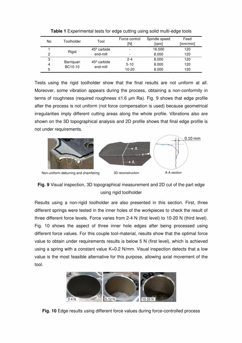
Table 1 Experimental tests for edge cutting using solid multi-edge tools
No Toolholder Tool Force control
[N]
Spindle speed
[rpm]
Feed
[mm/min]
1 Rigid
45º carbide
end-mill
- 16.500 120
2 - 8.000 120
3 Barriquan
BC10-10
45º carbide
end-mill
2-4 8.000 120
4 5-10 8.000 120
5 10-20 8.000 120
Tests using the rigid toolholder show that the final results are not uniform at all.
Moreover, some vibration appears during the process, obtaining a non-conformity in
terms of roughness (required roughness ≤1.6 µm Ra). Fig. 9 shows that edge profile
after the process is not uniform (not force compensation is used) because geometrical
irregularities imply different cutting areas along the whole profile. Vibrations also are
shown on the 3D topographical analysis and 2D profile shows that final edge profile is
not under requirements.
Non-uniform deburring and chamfering 3D reconstruction
A
A
A-A section
0.10 mm
Fig. 9 Visual inspection, 3D topographical measurement and 2D cut of the part edge
using rigid toolholder
Results using a non-rigid toolholder are also presented in this section. First, three
different springs were tested in the inner holes of the workpieces to check the result of
three different force levels. Force varies from 2-4 N (first level) to 10-20 N (third level).
Fig. 10 shows the aspect of three inner hole edges after being processed using
different force values. For this couple tool-material, results show that the optimal force
value to obtain under requirements results is below 5 N (first level), which is achieved
using a spring with a constant value K=0.2 N/mm. Visual inspection detects that a low
value is the most feasible alternative for this purpose, allowing axial movement of the
tool.
2-4 N 5-10 N 10-20 N
Fig. 10 Edge results using different force values during force-controlled process

Once established an appropriate force level, a check test was performed processing all
the contour of one of the bosses. Results show that all the profile was obtained with a
uniform chamfer, under tolerances. Fig. 11 shows the test part, 3D topography and
section cut.
A
A
3D reconstruction A-A sectionTest part
0.25 mm
Fig. 11 Visual inspection, 3D topographical measurement and section cut of the part
edge using force control
Using this tool and toolholder, deburring and edge cutting is performed in a correct
way. However, two secondary sharp edges are generated after chamfering. This
phenomenon should be avoided or minimized. Thus, a final step must be performed in
order to achieve a smooth edge, necessary for the final assembly and delivery
processes, when the component is finished.
7. Abrasive polishing of secondary edges
Brushing turns out to be a very extended operation when providing the last finishing
operation to the component, giving it a clean appearance with smoothed edges after
erasing secondary edges and the previous deburring marks. Brushing tools with high
abrasive capacity can be found nowadays in the literature [27], suitable for the removal
of small burrs as well, thus reducing the finishing stages and with it, the total machining
time and the operating costs of the process. Brushes used for this type of application
work while maintaining their normal orientation to the workpiece. The use of axial
compensation tools for this application provides the necessary pressure or force
control, preventing breakage due to overloading of the fibers and allowing for varying
material removal capacity. In this work, a flexible abrasive tool was used to smooth the
edges, as show in Fig. 12.

Spindle and force compensator
Flexible abrasive brushes
Fig. 12 Experimental set-up carried out using force controlled abrasive brushes
After polishing the test part, mechanical and optical cuts were performed to analyze the
final edge result. Fig. 13. shows the sharpness reduction on secondary edges,
providing an under-tolerance result of the edge.
Edge sectionEdge before polishing Edge after polishing
0.3 mm
Fig. 13 Visual inspection and 2D cut of the initial (before brushing) and final edge (after
brushing)
Taking into account the knowledge generated during the performance of this work, a
general estimation of the capability to automate the process can be proposed. In a
general view, it can be considered that using this methodology, approximately the 80%
of a whole aero-case component can be finished in an automated way. It can be
assumed that the other 20% must be completed in manual due to: i) robot accessibility
and capability to deal with complex geometries, and ii) manual rework due to non-
efficiently automated finishing. Assuming this approach, due to the higher velocity of
the automated process compared with the manual one (more than twice in speed), a
notable time saving can be introduced in the system. This reduction depends on the
part number, reference and other indicators, but at least, an estimated value of 10-15%
can be proposed as an initial point.

8. Conclusions
Technological methodology for automated finishing of aero-engine cases and similar
components was presented in this work. The technologies and processes tested, offer
to the aeronautical market a chance for automating operations in which final quality is
completely operator-dependent and not friendly in terms of health and safety. Results
provided in this work show the following key conclusions:
(1) 3D scanning using structured blue light allows not only edge detection, but also the
generation of new toolpath profiles to suit part geometry, compensating deviations
produced in previous stages of manufacture.
(2) Remaining minor deviations, those derived from the scanning/smoothing process
itself, are corrected by applying cutting tool force-compensation systems, keeping
the contact between tool and part as uniform as possible.
(3) The application of radial compensation strategies can be useful when removing
burrs with great root thickness. For the general case, the combination of tools with
conical cutting geometries and tool holders equipped with axial compensation was
shown the best results, transferring deviations of the part in oscillations absorbed by
the springs.
(4) Solid carbide end-mills provide high material removal rates deburring Inconel 718.
Thus, to remove this kind of burrs, the use of carbide tools is recommended, varying
force-compensation according to the size of the burrs and the chamfer required.
(5) For smaller burr sizes, or for secondary edge smoothing, flexible abrasive tools are
the recommended solution. Abrasive brushing was proven to be a feasible solution
for removing smaller burrs, thus enabling the reduction of deburring operations and
reducing process operating time.
These results allow to identify the key aspects to develop this methodology in the
future. In future work, efforts will be made to perform each stage in an automated way,
establishing optimum process conditions for all types of parts likely to be presented.

References
1. Rodríguez A, López De Lacalle LN, Fernández A, Braun S (2014) Elimination of
surface spiral pattern on brake discs. J Zhejiang Univ Sci A 15:53–60.
https://doi.org/10.1631/jzus.A1300236
2. Rodriguez A, de Lacalle LNL, Pereira O, et al (2020) Isotropic finishing of
austempered iron casting cylindrical parts by roller burnishing. Int J Adv Manuf
Technol 110:753–761. https://doi.org/10.1007/s00170-020-05894-7
3. Xu L Da, Xu EL, Li L (2018) Industry 4.0: state of the art and future trends. Int J
Prod Res 56:2941–2962. https://doi.org/10.1080/00207543.2018.1444806
4. Lu Y, Xu X, Wang L (2020) Smart manufacturing process and system
automation – A critical review of the standards and envisioned scenarios. J
Manuf Syst 56:312–325. https://doi.org/10.1016/j.jmsy.2020.06.010
5. Pang X, Zeng Y, Zhang J, Deng W (2021) Analytical model and experimental
verification of Poisson burr formation in ductile metal machining. J Mater
Process Technol 290:116966. https://doi.org/10.1016/j.jmatprotec.2020.116966
6. Gillespie L (1999) Deburring and edge finishing handbook. Society of
Manufacturing Engineers
7. Gillespie L (2003) Hand Deburring: Increasing Shop Productivity. Society of
Manufacturing Engineers
8. Ramachandran N, Pande SS, Ramakrishnan N (1994) The role of deburring in
manufacturing: A state-of-the-art survey. J Mater Process Technol 44:1–13.
https://doi.org/https://doi.org/10.1016/0924-0136(94)90033-7
9. Aurich JC, Dornfeld D, Arrazola PJ, et al (2009) Burrs-Analysis, control and
removal. CIRP Ann - Manuf Technol 58:519–542.
https://doi.org/10.1016/j.cirp.2009.09.004
10. Shafer F (1975) Product Design Influences on Deburring. Soc Manuf Eng 75–
483
11. (2017) ISO 13715 Technical product documentation: Edges of undefined shape
- indication and dimensioning

12. Ji W, Wang L (2019) Industrial robotic machining: a review. Int J Adv Manuf
Technol 103:1239–1255. https://doi.org/10.1007/s00170-019-03403-z
13. Driemeyer Wilbert A, Behrens B, Zymla C, et al (2015) Robotic finishing process
- An extrusion die case study. CIRP J Manuf Sci Technol 11:45–52.
https://doi.org/10.1016/j.cirpj.2015.07.002
14. Niknam SA, Davoodi B, Davim JP, Songmene V (2018) Mechanical deburring
and edge-finishing processes for aluminum parts—a review. Int J Adv Manuf
Technol 95:1101–1125. https://doi.org/10.1007/s00170-017-1288-8
15. Arunachalam R, Mannan MA (2000) Machinability of nickel-based high
temperature alloys. Mach Sci Technol 4:127–168.
https://doi.org/10.1080/10940340008945703
16. Zhu W Le, Beaucamp A (2020) Compliant grinding and polishing: A review. Int J
Mach Tools Manuf 158:103634.
https://doi.org/10.1016/j.ijmachtools.2020.103634
17. Ziliani G, Visioli A, Legnani G (2007) A mechatronic approach for robotic
deburring. Mechatronics 17:431–441.
https://doi.org/10.1016/j.mechatronics.2007.04.012
18. Kim C, Chung JH, Hong D (2008) Coordination control of an active pneumatic
deburring tool. Robot Comput Integr Manuf 24:462–471.
https://doi.org/10.1016/j.rcim.2007.04.003
19. Chen SC, Tung PC (2000) Trajectory planning for automated robotic deburring
on an unknown contour. Int J Mach Tools Manuf 40:957–978.
https://doi.org/10.1016/S0890-6955(99)00099-1
20. Sugita S, Itaya T, Takeuchi Y (2004) Development of robot teaching support
devices to automate deburring and finishing works in casting. Int J Adv Manuf
Technol 23:183–189. https://doi.org/10.1007/s00170-003-1602-5
21. Tsai JT, Lin CT, Chang CC, Chou JH (2015) Optimized positional compensation
parameters for exposure machine for flexible printed circuit board. IEEE Trans
Ind Informatics 11:1366–1377. https://doi.org/10.1109/TII.2015.2489578
22. Tsai JT, Yang PY, Chou JH (2018) Data-driven approach to using uniform
experimental design to optimize system compensation parameters for an auto-
alignment machine. IEEE Access 6:40365–40378.
https://doi.org/10.1109/ACCESS.2018.2856911

23. Tsai YT, Lee CH, Liu TY, et al (2020) Utilization of a reinforcement learning
algorithm for the accurate alignment of a robotic arm in a complete soft fabric
shoe tongues automation process. J Manuf Syst 56:501–513.
https://doi.org/10.1016/j.jmsy.2020.07.001
24. Leo Princely F, Selvaraj T (2014) Vision assisted robotic deburring of edge burrs
in cast parts. Procedia Eng 97:1906–1914.
https://doi.org/10.1016/j.proeng.2014.12.344
25. Azzam N, Chaves-Jacob J, Boukebbab S, Linares JM (2014) Adaptation of
machining toolpath to distorted geometries: Application to remove a constant
thickness on rough casting prosthesis. Int J Adv Manuf Technol 72:1073–1083.
https://doi.org/10.1007/s00170-014-5738-2
26. Lartigue C, Tournier C, Ritou M, Dumur D (2004) High-performance NC for HSM
by means of polynomial trajectories. CIRP Ann - Manuf Technol 53:317–320.
https://doi.org/10.1016/S0007-8506(07)60706-9
27. Kannan S, Kui L (2019) Experimental investigation of surface integrity during
abrasive edge profiling of nickel-based alloy. J Manuf Process 39:40–51.
https://doi.org/10.1016/j.jmapro.2019.01.052

Figures
Figure 1
Outer case component description
Figure 2
Edge location problems on boss shape features and edge �nishing requirements

Figure 3
Finishing methodology proposed for casting boss shape features

Figure 4
Robotic cell working in MOD1 for polishing and deburring operations
Figure 5
Burrs generated on test part, similar to burrs obtained in real component
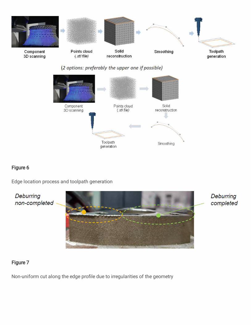
Figure 6
Edge location process and toolpath generation
Figure 7
Non-uniform cut along the edge pro�le due to irregularities of the geometry

Figure 8
Experimental set-up and cutting-edge requirements
Figure 9
Visual inspection, 3D topographical measurement and 2D cut of the part edge using rigid toolholder

Figure 10
Edge results using different force values during force-controlled process
Figure 11
Visual inspection, 3D topographical measurement and section cut of the part edge using force control

Figure 12
Experimental set-up carried out using force controlled abrasive brushes
Figure 13
Visual inspection and 2D cut of the initial (before brushing) and �nal edge (after brushing)