Embed Size (px)
Citation preview

EDGE - 540TSEMI SCALE SPORT MODEL
Assemblyand
Operations Manual
Please review this manual throughlyBefore assembling or Operating
TheVMAR EDGE - 540T
Semi scale sport model
EDGE - 540T
We’ve used our ULTRA TOUGH POLYCOTE ECS Enhanced Covering Systemfor this Model
TM
Liability DisclaimerIt is important that the following liability disclaimer be
READ BEFORE ASSEMBLING OR USING THIS PRODUCT.
Model airplanes, model engines, model engine fuel, propellers and products such as the EDGE - 540T semi scalesport model can be hazardous if improperly used. Be cautious and follow all safety recommendations when usingyour Model . Keep hands, tools, clothing and all foreign objects well clear of engines when they are operating. Takeparticular care to safeguard and protect your eyes and fingers and the eyes and fingers of other persons who maybe nearby. Use only a good quality propeller that has no cracks or flaws . Stay clear of the propeller and stay clearof the plane of rotation defined by the propeller.
The Manufacturer, Distributor, Retailer and/or other suppliers of this product expressly disclaim any warranties orrepresentations, either expressed or implied, including but not limited to implied warranties of fitness for the pur-poses of achieving and sustaining remotely controlled flight.
In no event will the Manufacturer, Distributor, Retailer and/or other suppliers of this product have any obligation aris-ing from contract or tort, or for loss of revenue or profit, or for indirect, special, incidental, consequential or otherdamages arising from the use of this product.
In purchasing and/or using this product, the user accepts all responsibility for its use and accepts all liability asso-ciated with such use.
Proceeding with assembly and use of this productIndicates
Agreement With and Acceptance of the Liability Disclaimer .
CAUTION.A Remote Control Model Aircraft is not a toy. It is a flying model that functions much like a full size airplane. If
you do not assemble and operate this product properly you can cause injury to yourself and others and damageproperty. DO NOT FLY this model if you are not qualified.
You are ultimately responsible for the mechanical, aeronautical and electrical integrity of this model and it’s struc-ture, control surfaces, hinges, linkages, covering, engine, radio, wiring, battery and all other components check
all components before and after each flight. Do not fly until it’s right!
INTRODUCTIONThank you for purchasing a VMAR product. VMAR Manufacturing is committed to delivering superior value to the
RC modeler. Your new EDGE - 540T is the market leader in features, ease of use and flexibility. Please reviewthese instructions before beginning the simple assembly procedure.
We’ve used metric measurements throughout these instructions. We know that some of you like metric while oth-ers think that furlongs per fortnight makes a nifty velocity indicator. If you are in the furlong camp, bear with us….It’s not a big deal…3 millimeters is stated as 3mm and 3mm is about 1/8 of an inch. Fire up your calculator andyou will find that 25.4 mm makes an inch. In places where you have to actually set up something according to a
recommended measurement, we’ve listed an approximate imperial measurement in inches in brackets.
Whenever we’ve used the directional terms left or right , they are with respect to the model when viewed as youwould when sitting in the cockpit…that is when viewed from the back looking forward.
2
INDEX.
Liability Disclaimer and Caution Page 2
Introduction Page 2
Check Out the Contents Page 3 - 5
Installing the wing Stage 1 Page 6
Fitting aileron servo Stage 2 - 3 Page 7 - 8
Installing the horizontal & vertical stabilizer Stage 4 - 11 Page 8 - 11
Installing the main landing gear Stage 12 Page 11
Installing the tail wheel Stage 13 Page 12
Installing the Fuel Tank Stage 14 Page 12
Installing the Engine Stage 15 Page 12 - 13
Fitting rudder and elelvator control horns Stage 16 Page 13
Installing the servos Stage 17 Page 14
Connecting the pushrods Stage 18 - 20 Page 14 - 15
Connecting the throttle control Stage 21 Page 15
Adjust control surface throw limits Stage 22 Page 15
Final RC setup Stage 23 - 24 Page 16
Installing radio equipment Stage 25 - 27 Page 16 - 17
Balancing the aircraft Stage 28 Page 17
Confirm mechanical integrity Stage 29 Page 17 - 18
CG and throw specifications Stage 29 Page 18
Cowl installation tips Page 18 - 20
Parts for your model Page 20
Notes Page 21 - 23
POLYCOTE ECS - What’s it all about ? Page 24
CHECK OUT THE CONTENTS.
You’ve taken the lid off the box and grabbed the instruction booklet…you are about 6-8 hours away being ready togo flying! Now is the time to look over what’s in the box. Please go through the contents and make sure nothinghas been damaged in shipping. Damage or missing components must be reported to your vendor BEFORE anyassembly begins. Please DO NOT START if something is damaged or missing. As you can imagine, once you jointhe wing halves or install your radio or engine your options for returns are very limited. Your vendor will not be ableto provide you with exchanges or replacements of parts that have been assembled. DO NOT START UNLESS IT’SRIGHT!
3
CHECK OFF COMPONENTS AND PARTS INCLUDED.Maijor components and sub-assemblies
Contents of master bag
Contents of main landing gear parts bag4 mounting screws 2 Axle assemblies with wheel collars
Contents of wheel pants and landing gear fairing bag1 landing gear cover 2 Wheel pants
Contents of wing parts bag
Contents of spinner parts bag1 spinner with allen screws1 Allen wrench1 Spinner shaft collet set
Contents of control horn parts bag
Contents of tail wheel parts bag1 Pre-assembled wire, wheel and bracked assembly2 Mounting screws
Contents of miscellaneous parts bag2 wood guide blocks with slot for control rod support1 Allen wrench for control rod EZ connector of fitted
Contents of spare parts bagAssortment of extra spare parts that are not required but may come in handy in service
In addition to the items in the parts bags the following items have been pre-installed or placed into the fuse-lage at the factory.
1 Fuel tank assembly with stopper, clunk and pre-bent metal tubing1 Universal adjustable servo tray with mounting screws and slider plates control rod assemblies including con-necting hardware.
4
1 Fuselage2 Wing halves (left and right)1 Vertical stabilizer with pre-installed rudder.1 Horizontal stabilizer with pre-installed elevator .1 Fiber glass cowl
1 Fiberglass main landing gear1 Documentation set including instruction booklet1 Set of patch and/or trim sheets if required1 Master bag
2 Engine mount T-beams (aluminum) with allenscrews2 Ulatralight treaded wheels1 Fibreglass main landing gear1 Main landing gear parts bag1 Wheel pants and landing gear cover
1 Wing parts bag1 Spinner parts bag1 Control horn parts bag1 Tail wheel parts bag1 Miscellaneous parts bag1 Spare parts bag
1 Wood spar joiner2 Wood alignment dowels1 Small roil of wing joint tape2 Aileron control rod assemblies with clevises
2 Plastic wing mouting bolts.
5 Metal bolts 3mm x 35-40mm 5 Metal nuts 3mm5 Plastic control horns
5 Plastic T - nuts 5 Plastic beveled washers
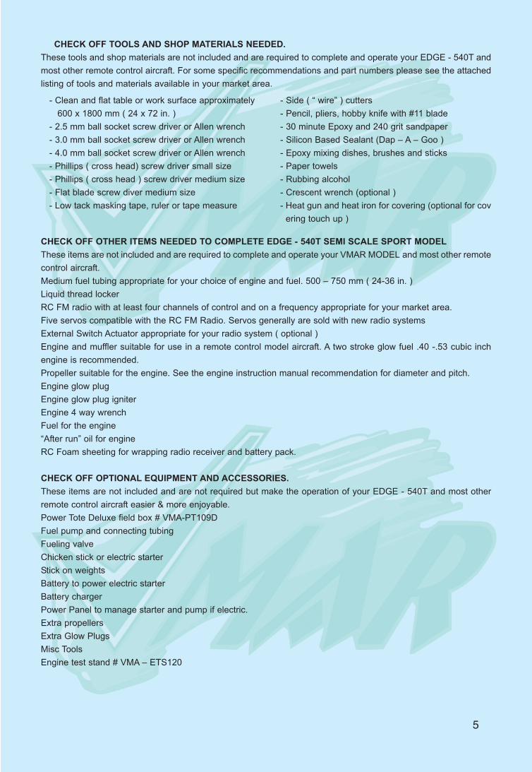
CHECK OFF TOOLS AND SHOP MATERIALS NEEDED.These tools and shop materials are not included and are required to complete and operate your EDGE - 540T andmost other remote control aircraft. For some specific recommendations and part numbers please see the attachedlisting of tools and materials available in your market area.
CHECK OFF OTHER ITEMS NEEDED TO COMPLETE EDGE - 540T SEMI SCALE SPORT MODELThese items are not included and are required to complete and operate your VMAR MODEL and most other remotecontrol aircraft. Medium fuel tubing appropriate for your choice of engine and fuel. 500 – 750 mm ( 24-36 in. )Liquid thread lockerRC FM radio with at least four channels of control and on a frequency appropriate for your market area.Five servos compatible with the RC FM Radio. Servos generally are sold with new radio systemsExternal Switch Actuator appropriate for your radio system ( optional )Engine and muffler suitable for use in a remote control model aircraft. A two stroke glow fuel .40 -.53 cubic inchengine is recommended.Propeller suitable for the engine. See the engine instruction manual recommendation for diameter and pitch.Engine glow plugEngine glow plug igniterEngine 4 way wrenchFuel for the engine“After run” oil for engineRC Foam sheeting for wrapping radio receiver and battery pack.
CHECK OFF OPTIONAL EQUIPMENT AND ACCESSORIES.These items are not included and are not required but make the operation of your EDGE - 540T and most otherremote control aircraft easier & more enjoyable.Power Tote Deluxe field box # VMA-PT109DFuel pump and connecting tubingFueling valveChicken stick or electric starterStick on weightsBattery to power electric starterBattery chargerPower Panel to manage starter and pump if electric.Extra propellersExtra Glow PlugsMisc ToolsEngine test stand # VMA – ETS120
5
- Clean and flat table or work surface approximately 600 x 1800 mm ( 24 x 72 in. )
- 2.5 mm ball socket screw driver or Allen wrench- 3.0 mm ball socket screw driver or Allen wrench- 4.0 mm ball socket screw driver or Allen wrench- Phillips ( cross head) screw driver small size- Phillips ( cross head ) screw driver medium size- Flat blade screw diver medium size- Low tack masking tape, ruler or tape measure
- Side ( “ wire” ) cutters- Pencil, pliers, hobby knife with #11 blade- 30 minute Epoxy and 240 grit sandpaper - Silicon Based Sealant (Dap – A – Goo )- Epoxy mixing dishes, brushes and sticks - Paper towels- Rubbing alcohol - Crescent wrench (optional )- Heat gun and heat iron for covering (optional for cov
ering touch up )
6
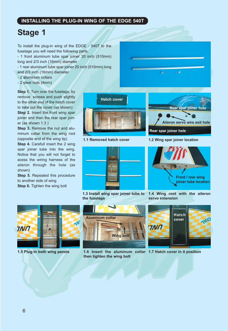
INSTALLING THE PLUG-IN WING OF THE EDGE 540T
To install the plug-in wing of the EDGE - 540T to thefuselage you will need the following parts.- 1 front aluminum tube spar joiner 20 inch (510mm)long and 2/3 inch (16mm) diameter- 1 rear aluminum tube spar joiner 20 inch (510mm) longand 2/3 inch (16mm) diameter- 2 aluminum collars - 2 steel nuts (4mm)
Stage 1
Step 1. Turn over the fuselage, byremove screws and push slightlyto the other end of the hatch coverto take out the cover (as shown)Step 2. Insert the front wing sparjoiner and then the rear spar join-er (as shown 1.3 )Step 3. Remove the nut and alu-minum collar from the wing root(opposite end of the wing tip)Step 4. Carefull insert the 2 wingspar joiner tube into the wing.Notice that you will not forget toacess the wiring harness of theaileron through the hole (asshown)Step 5. Repeated this procedureto another side of wingStep 6. Tighten the wing bolt
1.1 Removed hatch cover 1.2 Wing spar joiner location
Hatch cover
Aileron servo wire exit hole
Rear spar joiner hole
Rear spar joiner hole
1.3 Install wing spar joiner tube tothe fuselage
1.4 Wing root with the aileronservo extension
Front / rear wingjoiner tube location
1.5 Plug-in both wing panels 1.6 Insert the aluminum collarthen tighten the wing bolt
Aluminum collar
1.7 Hatch cover in it position
Wing bolt
Hatchcover
7
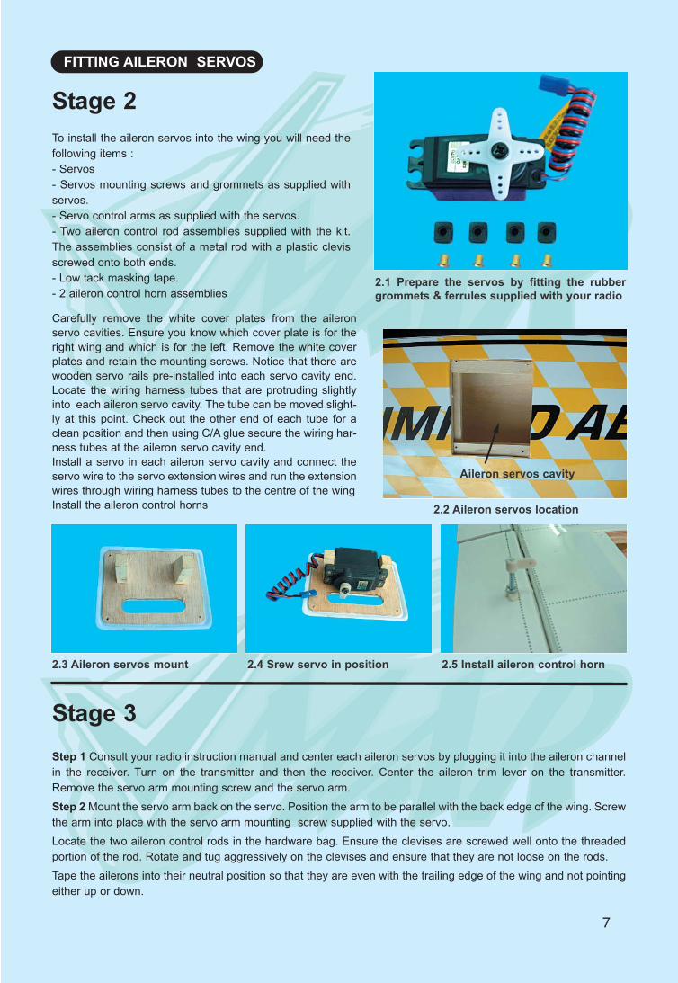
FITTING AILERON SERVOS
To install the aileron servos into the wing you will need thefollowing items :- Servos- Servos mounting screws and grommets as supplied withservos.- Servo control arms as supplied with the servos.- Two aileron control rod assemblies supplied with the kit.The assemblies consist of a metal rod with a plastic clevisscrewed onto both ends.- Low tack masking tape.- 2 aileron control horn assemblies
2.1 Prepare the servos by fitting the rubbergrommets & ferrules supplied with your radio
Stage 2
Carefully remove the white cover plates from the aileronservo cavities. Ensure you know which cover plate is for theright wing and which is for the left. Remove the white coverplates and retain the mounting screws. Notice that there arewooden servo rails pre-installed into each servo cavity end.Locate the wiring harness tubes that are protruding slightlyinto each aileron servo cavity. The tube can be moved slight-ly at this point. Check out the other end of each tube for aclean position and then using C/A glue secure the wiring har-ness tubes at the aileron servo cavity end.Install a servo in each aileron servo cavity and connect theservo wire to the servo extension wires and run the extensionwires through wiring harness tubes to the centre of the wingInstall the aileron control horns
2.3 Aileron servos mount 2.4 Srew servo in position 2.5 Install aileron control horn
Aileron servos cavity
2.2 Aileron servos location
Step 1 Consult your radio instruction manual and center each aileron servos by plugging it into the aileron channelin the receiver. Turn on the transmitter and then the receiver. Center the aileron trim lever on the transmitter.Remove the servo arm mounting screw and the servo arm.Step 2 Mount the servo arm back on the servo. Position the arm to be parallel with the back edge of the wing. Screwthe arm into place with the servo arm mounting screw supplied with the servo.Locate the two aileron control rods in the hardware bag. Ensure the clevises are screwed well onto the threadedportion of the rod. Rotate and tug aggressively on the clevises and ensure that they are not loose on the rods.Tape the ailerons into their neutral position so that they are even with the trailing edge of the wing and not pointingeither up or down.
Stage 3
8
Step 3 Ensure that the aileron control horns are screwed onto the threaded aileron control horn bolts and that bothcontrol horns are in approximately the same place on their respective bolts.Step 4 Connect the aileron servo rods to the aileron control horns. If one of the two clevises on each rod has ametal pin or screw, attach that clevis to the servo output arm.Step 5 Connect the other clevis to the servo output armStep 6 Remove the masking tape holding the ailerons.Step 7 In the case of computer radios the servos together by connecting them to the appropiate receiver channel. In the case of analog radios couple the servos together using a Y harnessStep 8 Turn on your radio and activate the ailerons, using the aileron stick and ensure a smooth full motion can beachieved.Step 9 With the wing top side up and viewed from the back, ensure that moving the transmitter aileron stick to theleft raises the left aileron and lowers the right aileron. Movement of the stick to the left will roll the aircraft to the left.(Counterclockwise roll of the wing when viewed from the back ).Step 10 With the wing top side up and viewed from the back, ensure that moving the transmitter aileron stick to theright raises the right aileron and lowers the left aileron. Movement of the stick to the right will roll the aircraft to theright.
3.1 Aileron control rod assembly 3.2 Aileron control horn assembly 3.3 Aileron control installed
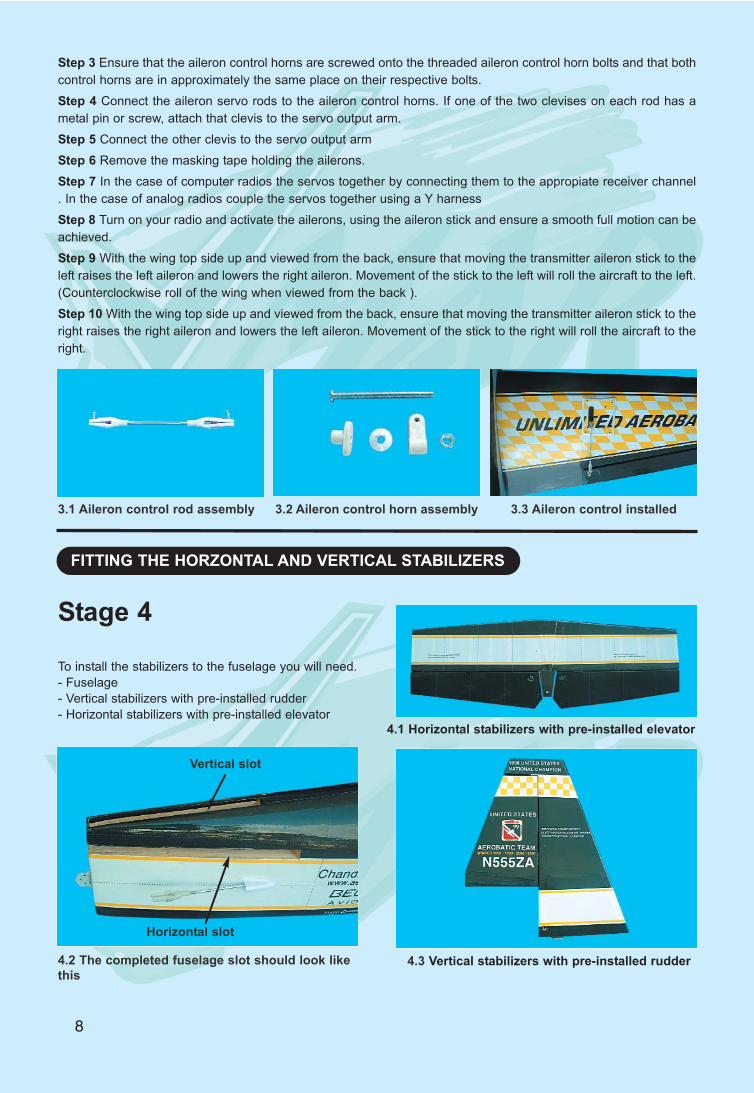
FITTING THE HORZONTAL AND VERTICAL STABILIZERS
To install the stabilizers to the fuselage you will need.- Fuselage- Vertical stabilizers with pre-installed rudder- Horizontal stabilizers with pre-installed elevator
4.2 The completed fuselage slot should look likethis
Vertical slot
Horizontal slot
4.1 Horizontal stabilizers with pre-installed elevator
4.3 Vertical stabilizers with pre-installed rudder
Stage 4
9
Check the fit of the horizontal stabilizerin its slot. Make sure the tail is squareand centred to the fuselage by takingmeasurements as shown in the dia-grams on the right, but don’t glue any-thing yet. Equal
distance
Equal distance900
5.1 Trial fit the horizontal stabilizer inits slot
With the horizontal stabilizer cor-rectly aligned, mark the shape of thefuselage on the top and bottom ofthe tailplane using a water sol-ublenon-permanent felt-tip pen asshown here.
6.1 Mark the top of the horizontalstabilizer
6.2 Followed by the bottom
Stage 5
Stage 6
Stage 7Now remove the horizontal stabiliz-er and, using a sharp knife and aruler CAREFULLY cut 2mm insidethe marked lines and remove thecovering on the top and bottom ofthe tail as shown. Make sure youonly cut the film and not the wood,otherwise the horizontal stabilizerwiil be severely weakened.
7.1 Marked lines on horizontalstab
7.2 Cutting inside the lines
7.3 Removed covering from topsurface
7.4 Exactly the same underneath 7.5 Clean off any traces of pen
10
Now apply sufifciant epoxy to the top and bottom of thehorizontal stabilizer. Use 30 minute epoxy to ensure astrong bond and give yourself plenty of working time.
Insert the horizontal stabilizerl in its slot in the fuselageand re-check the alignment as in Stage 9. Excess epoxyshould be cleaned off with a rag or tissue before it cures.
8.1 Apply plenty of epoxy 8.2 Slide the horizontal stabilizerin place
8.3 Wipe off excess epoxy
Check the fit of the vertical stabilizer in its slot.To make sure that it is glued square to the hori-zontal stabilizer and fuselage
FITTING THE VERTICAL STABILIZER WITH RUDDER
9.1 Trial fit the vertical stabilizer onto fuselage.
Stage 8
Stage 9
10.1 Mark both sides of the verti-cal stabilizer
10.2 Carefully cut through thecovering
10.3 Remove covering from bothsides
Mark the shape of the fuselage on the left and rightsides of the vertical stabilizer using a felt-tip pen. Nowremove the vertical stabilizer and, using a sharp knife& ruler, CAREFULLY cut just 2mm inside
the marked lines and remove the covering on bothsides of the fin, just as you did with the horizontal sta-bilizer, taking sure you only press hard enough to cutthe covering, not the vertical stabilizer.
Stage 10
11
Now apply sufficient epoxy to both sides and the bottomof the vertical stabilizer. Use 30 minute epoxy to ensurea strong bond and give yourself plenty of working time.
Insert the vertical stabilizer in its slot in the fuselageand re-check the alignment. Excess adhesive shouldbe cleaned off with a rag or tissue before it cures.
11.1 Apply plenty of epoxy 11.2 Slide the fin in place 11.3 Insert the pre-installed hingeto the rudder
FITTING THE MAIN LANDING GEAR
Identify the main landing gear components shownbelow- 1 fiberglass main landing gear- 2 axle assembly- 2 main wheels ( 60mm x 20mm)- 2 wheels pants- 1 Landing gear cover- 4 sheet metal screws 5 x 35 mm with washers- 1 tail wheel assembly with 2 (3 x 15mm) sheet metalscrews. 12.1 Main landing gear components
Stage 11
Stage 12
12.2 Turn over the fuselage tolocated the 4 pre-drilled mainlanding gear mounting holes
12.4 Install the wheel pan andwheel to the main landing gear
12.5 Use 4 metal sheet screws (5 x35mm) to mount the main landinggear onto the fuselage
12.6 Drill a hole to install the mainlanding gear cover
12.3 Install the axle and wheel
12.7 Main landing gear coverinstalled
12
FITTING THE TAIL WHEEL
13.1 Insert the tail wheel steeringwire into the steering guide tube
13.2 Screw the tail wheel assem-bly to the fuselage
13.3 Trim off the excess tail steer-ing wire
Install the tail wheel assembly. Note that the tail wheelassembly has a loose wire end. Slide the loose wireend into the sleeve tube that has been installed intobottom of the rudder. Position the plastic bracket on
the bottom of the fuselage. Mark the location of thescrew holes. Tap the holes with the screws and thenfasten the plastic bracket to the fuselage. See theillustration below.
FITTING THE FUEL TANK
To assemble the fuel tank you will need the followingitems:- The fuel tank and fuel stopper assembly (supplied)- The clunk (supplied)- About 7” (20 cm) of medium ID silicone fuel line (DUB197 or similar)- Cross head Philips screw driver
Stage 13
Stage 14
14.1 Use 100 mm (4 in) for fuel lineand 50 mm (2 in) for pressure line
14.2 Illustration of fuel line posi-tioning inside the tank
14.3 Fuel tank installed on thepower module
100 mm (4 in) for fuel line
50 mm (2 in) for pressure line
fuel line
pressure line fuel line
pressure line
INSTALLING THE ENGINE
The engine and the fuel tank are installed onto thepower module. First remove the power module fromthe fuselage by removing the 4 nuts & washers power module
Stage 15
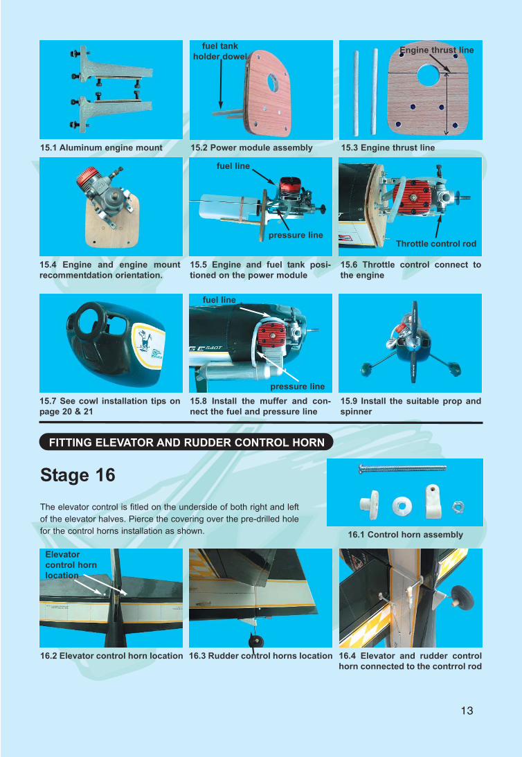
13
15.1 Aluminum engine mount 15.2 Power module assembly 15.3 Engine thrust line
fuel tank holder dowel
Engine thrust line
15.4 Engine and engine mountrecommentdation orientation.
15.5 Engine and fuel tank posi-tioned on the power module
15.6 Throttle control connect tothe engine
fuel line
pressure lineThrottle control rod
15.7 See cowl installation tips onpage 20 & 21
15.8 Install the muffer and con-nect the fuel and pressure line
15.9 Install the suitable prop andspinner
fuel line
pressure line
FITTING ELEVATOR AND RUDDER CONTROL HORN
The elevator control is fitled on the underside of both right and leftof the elevator halves. Pierce the covering over the pre-drilled holefor the control horns installation as shown.
16.2 Elevator control horn location 16.3 Rudder control horns location 16.4 Elevator and rudder controlhorn connected to the contrrol rod
16.1 Control horn assembly
Elevatorcontrol hornlocation
Stage 16
14
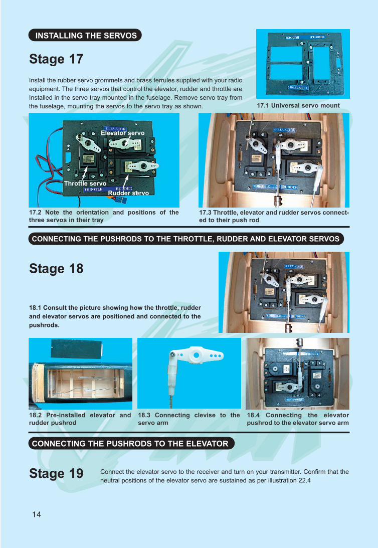
INSTALLING THE SERVOS
Install the rubber servo grommets and brass ferrules supplied with your radioequipment. The three servos that control the elevator, rudder and throttle areInstalled in the servo tray mounted in the fuselage. Remove servo tray fromthe fuselage, mounting the servos to the servo tray as shown. 17.1 Universal servo mount
17.2 Note the orientation and positions of thethree servos in their tray
Throttle servo
Elevator servo
Rudder servo
17.3 Throttle, elevator and rudder servos connect-ed to their push rod
18.1 Consult the picture showing how the throttle, rudderand elevator servos are positioned and connected to thepushrods.
CONNECTING THE PUSHRODS TO THE THROTTLE, RUDDER AND ELEVATOR SERVOS
Stage 17
Stage 18
18.2 Pre-installed elevator andrudder pushrod
18.3 Connecting clevise to theservo arm
18.4 Connecting the elevatorpushrod to the elevator servo arm
Connect the elevator servo to the receiver and turn on your transmitter. Confirm that theneutral positions of the elevator servo are sustained as per illustration 22.4
CONNECTING THE PUSHRODS TO THE ELEVATOR
Stage 19
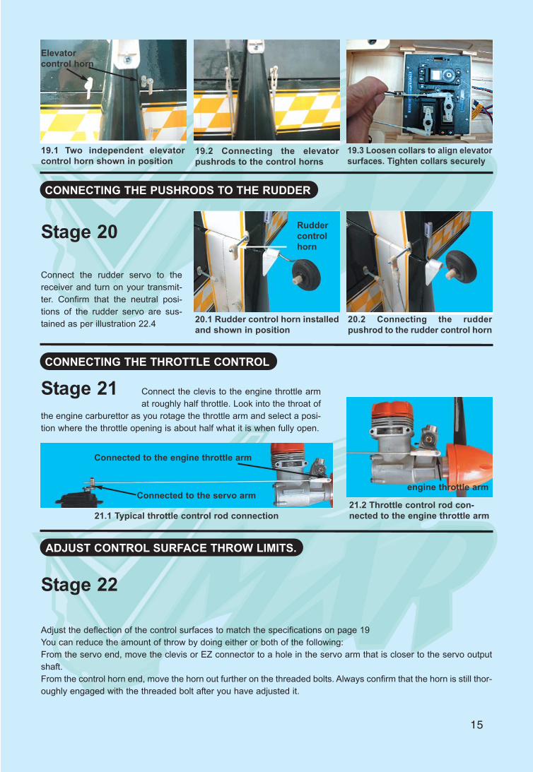
15
CONNECTING THE PUSHRODS TO THE RUDDER
Connect the rudder servo to thereceiver and turn on your transmit-ter. Confirm that the neutral posi-tions of the rudder servo are sus-tained as per illustration 22.4 20.1 Rudder control horn installed
and shown in position20.2 Connecting the rudderpushrod to the rudder control horn
CONNECTING THE THROTTLE CONTROL
19.1 Two independent elevatorcontrol horn shown in position
19.2 Connecting the elevatorpushrods to the control horns
19.3 Loosen collars to align elevatorsurfaces. Tighten collars securely
Elevatorcontrol horn
Stage 20 Ruddercontrolhorn
Stage 21
21.1 Typical throttle control rod connection
Connected to the engine throttle arm
engine throttle arm
21.2 Throttle control rod con-nected to the engine throttle arm
Connect the clevis to the engine throttle armat roughly half throttle. Look into the throat of
the engine carburettor as you rotage the throttle arm and select a posi-tion where the throttle opening is about half what it is when fully open.
Connected to the servo arm
Adjust the deflection of the control surfaces to match the specifications on page 19You can reduce the amount of throw by doing either or both of the following:From the servo end, move the clevis or EZ connector to a hole in the servo arm that is closer to the servo outputshaft.From the control horn end, move the horn out further on the threaded bolts. Always confirm that the horn is still thor-oughly engaged with the threaded bolt after you have adjusted it.
ADJUST CONTROL SURFACE THROW LIMITS.
Stage 22
16
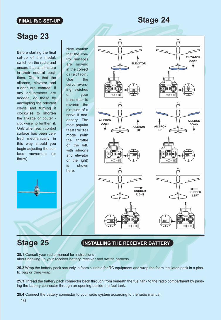
FINAL R/C SET-UP
Before starting the finalset-up of the model,switch on the radio andensure that all trims arein their neutral posi-tions. Check that theailerons, elevator andrudder are centred. Ifany adjustments areneeded, do these byuncoupling the relevantclevis and turning itclockwise to shortenthe linkage or couter -clockwise to lenthen it.Only when each controlsurface has been cen-tred mechanically inthis way should youbegin adjusting the sur-face movement (orthrow)
Now confirmthat the con-trol surfacesare movingin the correctd i r e c t i o n .Use theservo revers-ing swicheson yourtransmitter toreverse thedirection of aservo if nec-essary. Themost populart ransmi t te rmode (withthe throttleon the left,with aileronsand elevatoron the right)is shownhere.
Stage 24
ELEVATORUP
ELEVATORDOWN
AILERONUP
AILERONDOWN
AILERONDOWN
AILERONUP
RUDDERRIGHT
RUDDERLEFT
Stage 23
INSTALLING THE RECEIVER BATTERYStage 2525.1 Consult your radio manual for instructions about hooking up your receiver battery, receiver and switch harness.
25.2 Wrap the battery pack securely in foam suitable for RC equipment and wrap the foam insulated pack in a plas-tic bag or cling wrap.
25.3 Thread the battery pack connector back through from beneath the fuel tank to the radio compartment by pass-ing the battery connector through an opening beside the fuel tank.
25.4 Connect the battery connector to your radio system according to the radio manual.
17
Stage 26 INSTALLING THE RECEIVER
Stage 27 COMFIRM RADIO OPERATION
26.1 Consult your radio manual for instructions about hooking up your receiver.
26.2 Plan where you are going to put the receiver with consideration for routing the antenna safely.
26.3 Wrap the receiver securely in foam suitable for RC equipment and wrap the foam insulated receiver in a plas-tic bag or cling wrap.
26.4 Generally in the absence of specific instructions from the radio manufacturer, it is recommended that thereceiver should be placed where it is least likely to have impact during a crash. Keep the battery pack and otherheavy loose items ahead of the receiver.
27.1 Consult your radio manual for instructions about testing and operating your radio system.
27.2 Pay particular attention to charging your radio system batteries and range testing the system before and aftereach flight.
Check that all controls are working correctlybefore and after each flight.
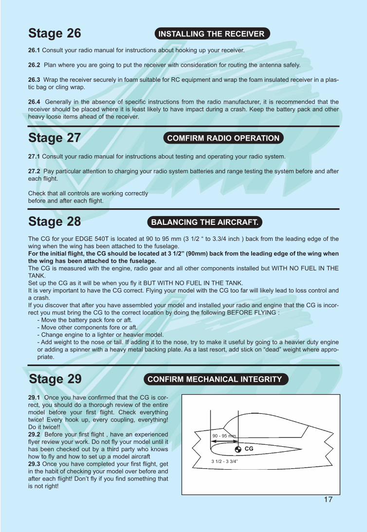
Stage 28The CG for your EDGE 540T is located at 90 to 95 mm (3 1/2 “ to 3.3/4 inch ) back from the leading edge of thewing when the wing has been attached to the fuselage.For the initial flight, the CG should be located at 3 1/2” (90mm) back from the leading edge of the wing whenthe wing has been attached to the fuselage.The CG is measured with the engine, radio gear and all other components installed but WITH NO FUEL IN THETANK.Set up the CG as it will be when you fly it BUT WITH NO FUEL IN THE TANK.It is very important to have the CG correct. Flying your model with the CG too far will likely lead to loss control anda crash.If you discover that after you have assembled your model and installed your radio and engine that the CG is incor-rect you must bring the CG to the correct location by doing the following BEFORE FLYING :
- Move the battery pack fore or aft.- Move other components fore or aft.- Change engine to a lighter or heavier model.- Add weight to the nose or tail. If adding it to the nose, try to make it useful by going to a heavier duty engineor adding a spinner with a heavy metal backing plate. As a last resort, add stick on “dead” weight where appro-priate.
BALANCING THE AIRCRAFT.
29.1 Once you have confirmed that the CG is cor-rect, you should do a thorough review of the entiremodel before your first flight. Check everythingtwice! Every hook up, every coupling, everything!Do it twice!!29.2 Before your first flight , have an experiencedflyer review your work. Do not fly your model until ithas been checked out by a third party who knowshow to fly and how to set up a model aircraft 29.3 Once you have completed your first flight, getin the habit of checking your model over before andafter each flight! Don’t fly if you find something thatis not right!
Stage 29 CONFIRM MECHANICAL INTEGRITY
90 - 95 mm
3 1/2 - 3 3/4”
CG
Cowl Installation TipsYou may have your own method to adapt and install the cowl to fit your model, your choice of engine and yourchoice of engine orientation... here is one method to add to your bag of tricks!
1) Use a sheet of card stock or better yet a sheet of clear thin plastic like that used to protect documents. Usinga clear sheet is strongly recommended.2) Wrap the sheet as close as possible around the cowl, preferably tapered slightly towards the front. Tape thesheet so that it stays in cylindrical shape approximating the cowl. Trim the aft edge of the sheet to approximatelymatch the aft edge of the cowl. Trim the front edge of the sheet to approximately match the front edge of thecowl. Put a couple of registration marks on the dummy cowl and real cowl so that you can apply the dummycow over the real cowl and real cowl in a similar manner again. Now remove the sheet from the cowl, in oncepiece if possible. If it is not possible to remove the sheet in one piece, use a felt tip pen to mark the sheet sothat you can untape it, the remove it from the cowl and then retape it back together into the cylindrical approx-imation of the cowl. In effect you now have a rough dummy cowl that can be used to make a template to helpyou later fit the real cowl.3) Now install the engine on the engine mounts and measure the distance from the back of the engine mountto the front of the thrust washer4) Draw a vertical line on the forward face of the firewall so that it is in the middle of the firewall and at rightangles to the horizontal line drawn on the firewall at the factory. If there is no horizontal line on the firewall, checkthe set up specs for this model and draw the horizontal thrustline at the location indicated.5) Install the real cowl on the model and slide the cowl back until the distance from the firewall to the cowl bosering hole is similar to the distance measured in step 4 AND that at least 1/4 in (6mm) of the edge of the cowloverlaps the front of the fuselage. Carefully square the cowl with respect to the fuselage so that it looks alignedfrom the top, sides, bottom and front. Look through the cowl nose ring hole and try to align the centre of the cowlnose ring hole with the intersection of the vertical and horizontal thrust lines onthe front face of the power mod-ule. Measure the distance from the forward face of the firewall to the nose ring hole in the cowl. Use low tackmasking tape to hold the cowl loosely in place while you adjust it. Once you have the cowl squared up and setwhere you want if fore and aft, apply a line of low tack masking tape around the circumference of the fuselage
18
Elevator Aileron Rudder
5/8”13mm
5/8”13mm
1/4”8mm
1/4”8mm
1/3”7mm
1/3”7mm
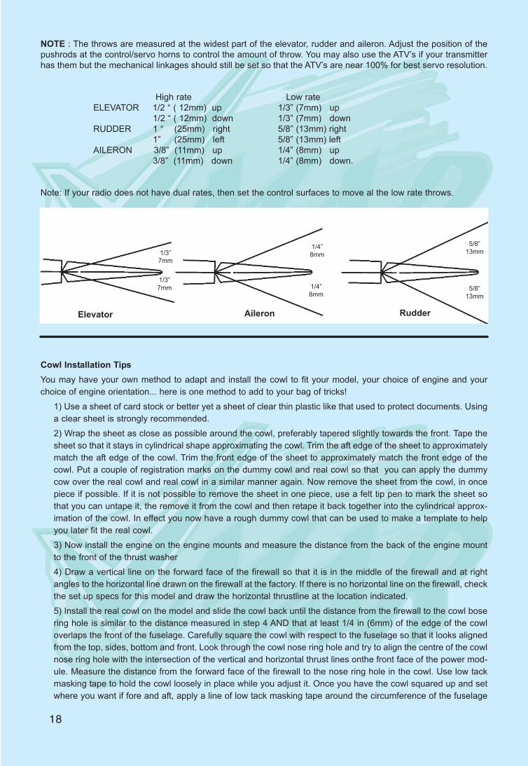
NOTE : The throws are measured at the widest part of the elevator, rudder and aileron. Adjust the position of thepushrods at the control/servo horns to control the amount of throw. You may also use the ATV’s if your transmitterhas them but the mechanical linkages should still be set so that the ATV’s are near 100% for best servo resolution.
High rate Low rateELEVATOR 1/2 “ ( 12mm) up 1/3” (7mm) up
1/2 “ ( 12mm) down 1/3” (7mm) downRUDDER 1 “ (25mm) right 5/8” (13mm) right
1” (25mm) left 5/8” (13mm) leftAILERON 3/8” (11mm) up 1/4” (8mm) up
3/8” (11mm) down 1/4” (8mm) down.
Note: If your radio does not have dual rates, then set the control surfaces to move al the low rate throws.
so that the forward edge of the masking tape just butts up against theaft edge og the cowl.6) Remove the real cowl from the model.7) Install your engine mount and engine and muffer onto the model. Orient the engine to the possition youwant...i.e upright, rotated 45 degrees inverted ect. Make sure the muffer and the carburetor are installed. Whenselecting which orientation you want for the engine you need to keep inmind operational considerations... themuffer for examle must clear the sides of the fuselage by at least 5mm and carburetor throttle arm must be con-nectable to the thottle control rod running forward through the firewall from the throttle servo. Lastly, the fuellines coming through the stopper hole in the run to the muffer pressure tap and the carburetor fuel nipple.8) Once you have positioned your engine mount and engine, secure them to the forward firewall of the powermodule and install the forward firewall onto the model using the four mounting studs, nuts and washers. We rec-ommend setting the forward firewall at zero degrees offset thrust for now. Use the same number of washers andnuts on all four studs. You can adjust a bit of right or down thrust into the firewall later if required.9) Remove the muffer and carburetor from the engine. Set the muffer and carburetor aside. Be careful not tolose any parts.10) Now try to fit the dummy cowl on to the fuselage. You will find that the dummy cowl will likely be obstructedby the engine as you try to install it. Assuming you are using the recommended clear sheet material you will beable to see whre the obstruction begins. Using a left tip marker mark the area onthe dummy cowl to fit over theengine.11) Remove the dummy cowl and cut away the area that you have marked. We suggest cutting away less thanyou think at first and expanding the cut out area in small incremental steps. Repeat this trial and error processuntil the dummy cowl can be installed with rear edge of the dummy cowl aligned with the forward edge of theline of tape onthe fuselage. You will have to repeat this process numerous times and we recommend workingin small steps. If you overdue a cut, use masking tape to ftll in the over cut area.12) Once you can install the dummy cowl over the engine, remove the dummy cowl and install the carburetorback on the engine.13) Now try to fit the dummy cowl on to the fuselage with the carburetor in place. You will find the carburetor-may obstruct the dummy cowl as you try to fit the dummy cowl into place. Mark the arear on the dummy cowlwhere you have to make a cutout for the carburetor...remove the dummy cowl, cut out the area carefully and tryagain. Repeat this trial and error process until the dummy cowl can be installed over the engine and carburetorproperly. Now check that you have acess to the needle valve and idle mix screws and any other carburetoradjustment settings...cut out access holes and areas to provide access.14) We are just about done with the dummy cowl work.. one more step! Install the muffer back on to the engine.15) Now try to fit the dummy cowl on to the fuselage with the muffer in piace. You will find that the muffer willobstruct the dummy cowl as you try to fit the dummy cowl into place. Mark the area on the dummy cowl whereyou have to make a cutout for the muffer... remove the dummy cowl, cut out the area careflly and try again.Repeat this trail and error process until the dummy cowl can be installed over the engine, Carburetor and muf-fer properly.16) Once you have the dummy cowl fitting onto the fuselage over the engine muffer and carburetor you areready to work on the real cowl. Take the dummy cowl and apply it over the real cowl. Align the registration marksyou made earlier. Using a fetl tip non-permanent marker, trace around the inside of the cutout areas of thedummy cowl...transferring the outline of the cutout areas to the real cowl.17) To carve the cut out areas in the fiberglass cowl we recomment using a half inch drum sander and a Dremeltool. Usee glasses and avoid the fiberglass dust. Wear gloves and a mask. Work in an erea with good ventila-tion. If you do not have a drum sander and Dremel tool, use a 1/8” drill to make a series of filot holes aroundthe cut area and then enrlage the drill holes until you can insert a rough hand file. Then expand the cut out areasusing the file. In either case, start from the interior of a cut out area and work outwards towards the perimeterline you drew on the cowl with the marker. Trial fit the cowl onto the engine and fuselage frequently as you go.Expand the cut out areas until the cowl fits with its aft edge adjacent to the tape line that you applied to the fuse-lage.18) Now adjust the alignment of the cowl so that the engine crankshaft is centered in the hole in the front faceof the cowl.19) Remove the tape line from the fuselage and move the cowl fore or aft until the foreward face of the engine
19
thrust washer is just forward of the cowl. Reapply a low tack masking tape line around the circumference of thefuselage so that the forward edge of the tape butts against aft edge of the cowl.20) Plan on drilling three pilot holes in the cowl for mounting screws. You want the screws to go into centre ofedge of the rear firewall not the forward removable firewall. Plan on having one screw go through the rear edgeof the top of the cowl and one on each side. Mark the locations of the holes onthe cowl.21) Drill a 1/32” pilot hole in the cowl and into the edge of the rear firewall. Adjust locations slightly if neededand drill a 1/6” hole. Use three # 2 or # 3 x 1/2” (wood screws to mount the cowl. We recommend drilling over-size holes in the cowl and fitting rubber grommets to provent the screws fron chaffing and expanding the cowlscrew holes.22) Now apply any trim sheets that are specified for this model. Check out the box artwork and instructions.Align the trim lines to the fuselage if required.
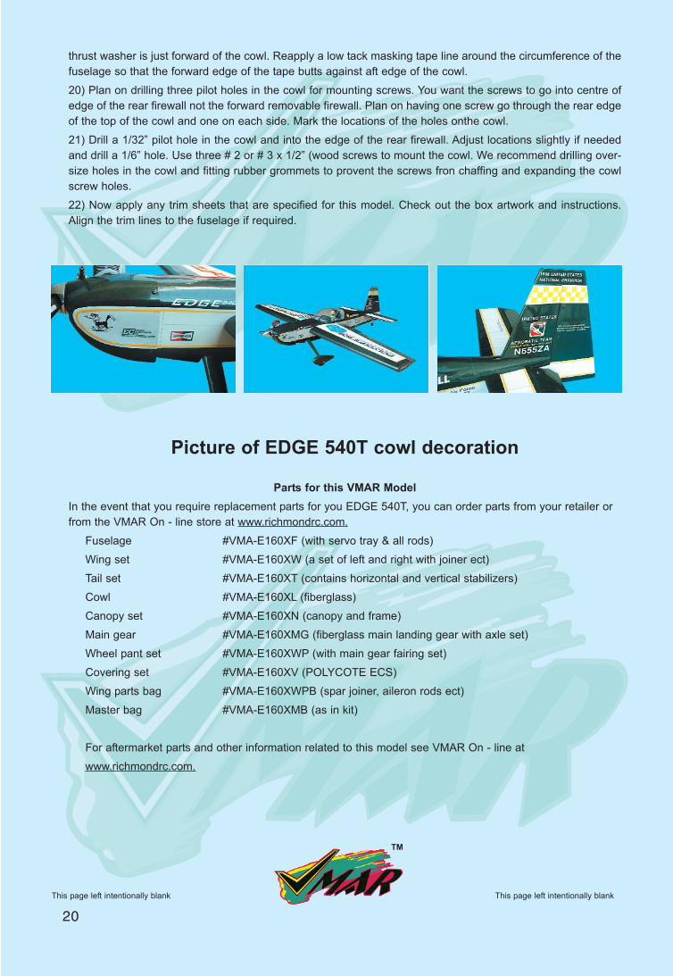
Picture of EDGE 540T cowl decoration
Parts for this VMAR ModelIn the event that you require replacement parts for you EDGE 540T, you can order parts from your retailer orfrom the VMAR On - line store at www.richmondrc.com.
Fuselage #VMA-E160XF (with servo tray & all rods)Wing set #VMA-E160XW (a set of left and right with joiner ect)Tail set #VMA-E160XT (contains horizontal and vertical stabilizers)Cowl #VMA-E160XL (fiberglass)Canopy set #VMA-E160XN (canopy and frame)Main gear #VMA-E160XMG (fiberglass main landing gear with axle set)Wheel pant set #VMA-E160XWP (with main gear fairing set)Covering set #VMA-E160XV (POLYCOTE ECS)Wing parts bag #VMA-E160XWPB (spar joiner, aileron rods ect)Master bag #VMA-E160XMB (as in kit)
For aftermarket parts and other information related to this model see VMAR On - line at www.richmondrc.com.
20This page left intentionally blank
TM
This page left intentionally blank

NotesNotes
This page left intentionally blank
TM
This page left intentionally blank
21

NotesNotes
This page left intentionally blank
TM
This page left intentionally blank
22

NotesNotes
This page left intentionally blank
TM
This page left intentionally blank
23

Your VMAR EDGE 540T Model is covered in POLYCOTE ECS.The new ULTRA TOUGH POLYESTER covering from VMAR !
WHAT’S ITALL ABOUT ?
POLYCOTE ECS is an Enhanced Covering System Engineered inCanada and Available only from VMAR. With POLYCOTE ECS thegraphics are inside the covering... not stuck on top. No Decals! NoLayers! No Strips! No Stripes! VMAR Models using POLYCOTEECS have very few seams and our proprietary SURE SEAL systemensures that the seams stay down! Best of all, POLYCOTE itself isa totally fuel proof ULTRA TOUGH POLYESTER
EDGE 540T
TM
TM