Embed Size (px)
Citation preview

05/03/14
TX Series
Key Features:
- High resolution (submicrometer)
- High dynamics (124 kS/s)
- Minimal temperature coefficient
- Configurable analogue output
- CAN Interface
- USB Interface
- eddyLAB, Windows software
oscilloscope + FFT + data logger
- Protection class IP68
- High noise immunity
- Custom-made probes
Contents:
Introduction & Applications ....2
Description ....3
eddyLAB Software ....4
Technical Data ....5
Resolution & Temperature ....7
Properties & Calibration ....8
USB / CAN / Connection ....9
Technical Drawings ..10
Accessories ..12
Installation ..13
Precautions & Order Code ..15
EDDY CURRENT PROBES

For more than ten years we have been occupied with the development and production of high-
quality eddy current probes for industry and research. With the new TX Series, WayCon is
introducing a fully digital device – incorporating USB, CAN and a high-speed analogue interface.
Eddy current probes are particularly suitable devices for non-contact measurements on metallic
targets. Typical applications are measurements on rotating shafts for the detection of imbalance,
vibration, out-of-roundness, air gap, radial/axial run-out, and much more besides. The extremely
high resolution up to level of 20nm enables the smallest of amplitudes to be detected. WayCon
probes are designed for temperatures up to 185 °C, and are optimised for the entire temperature
range with regard to temperature drift.
The basic principle
The principle of measurement bases on a DSP-driven oscillating circuit made up of the probe
(inductance) and a interconnect capacitance. This circuitry is attenuated in the presence of metallic
objects. The oscillating circuit generates magnetic field lines - these induce eddy currents on the
surface of conductive objects. The eddy currents counteract their cause and attenuate the amplitude
of the oscillating circuit.
This effect is decoupled from the oscillating circuit a fed towards further signal processing.
Outstanding temperature coefficient – Zero TC
A remarkable feature is the TX-Serie's temperature coefficient (TC). The temperature coefficient is
optimized in a range between -60°C..185 °C.
For certain boundary conditions the position will be constant at ambient temperature and 150°C.
This matter of fact can interpreted as Zero TC. Particularly when it comes to high-resolution
measurements this effect is of seminal importance.
Minimal probe drift
Every probe produced in WayCon's facility line is treated with a thermal finishing procedure of a 12-
hour duration (burn-in). This procedure minimises aging and drift. The probe is then finally calibrated
in our laboratory before delivery.
INTRODUCTION
APPLICATIONS
- 2 -
coil
Eddy Current Model Illustration
probe housing
measurement fieldeddy current
object
High-resolution distance measurements on
metallic objects regardless of non-conductive
mediums in the measurement area. Examples
are polymers, glass, oil, water, dirt.
Measurement of thermal expansion with a
maximum resolution of 20 nm.
Measurement of vibration and oscillation on
rotating shafts. Measurement of out-of-
roundness and radial displacement.
Surveillance and monitoring of rotating
mechanical components. Bearing wear and
lubrication gap.
Deformation and oscillation of gearwheels in
operation. Axial thrust measurement of helical
cut gears under load. Detection of tooth loss
on gearwheels.
Inspection and part quality analysis during
production in the presence of cooling lubricant.
Detection of gearing. Groove detection.
Detection of flat portions on shafts.
Thickness measurement of sheet material and
foils. Two-sided measurement for thickness
measurement. Controlling of machinery (feed-
back, closed-loop).
Weld seam positioning via edge detection.
Welding torch tracking. Surveillance of weld
seams. Out-of-roundness measurement on
welded drums and tubes.
Housing deformation of machines under load
such as gearboxes, engines, turbo generators.
Measurement of torsion on shafts and housing.
Measurement of thermal expansion.
Distance-time diagram for measurement
probes covered on the side. The measured
object passes by the probe laterally.
Measurement of object acceleration and
deceleration.
Layer thickness of non-conductive material
such as powder coatings and paint. Inspection
of plastic injection-moulded parts at insert
moulded metal parts.
........and many more

- 3 -
EDDY CURRENT BASIC MODULE TX
CUSTOM MADE
The processor based design admits lowest temperature coefficients – which are an exceptional feature for this
sensor technology. Remarkable performance allows highly dynamic measurements with 124 kS/s and linearities of
less than 0.1 %.
The eddy current basic module is available as single- or dual-channel device. As standard, the device provides a
USB and a CAN-bus Interface. The power supply is a galvanically isolated wide input from 10.5..36 VDC.
Supply:
Wide-Input-supply 10,5...36 VDC,
screwable M12 connector for shielded
cables; galvanically isolated.
CAN bus:
Data transfer via CAN bus for diverse
systems with multi channel
measurement.
USB connection:
Interface to PC and data transfer. Usage
of eddyLAB software. Direct
communication via USB protocol.
Extended measurement ranges
The powerful TX eddy current basic module admits customisation of our probes to your needs. The
measurement range can be extended up to 50 % - depending on the probe.
X-Z system
Axial thrust measurements on shafts without face access can be performed with the X-Z system. The
radial and the axial displacement can be measured on the lateral side.
Pressure-resistant probes
In accordance with your needs we also produce pressure-resistant probes in stainless steel and
ceramics. These probes can be applied in absolute and differential-pressure systems.
Water cooled
When it comes to ultra-hot conditions we offer probes with integrated cooling channels for
connection to a cooling system.
Custom-made
If your application requires non-standard dimensions we also produce shortened and extended
housing as shielded and non-shielded probes.
supplyM12 connector
CAN-BUSand opto-I/O
USB connector
probe 1
output 1
output 2
probe 2
Probe and analogue output:
isolated output and high-speed signals
via BNC connector. Selectable output
signals 10 V, 5 V, ±5 V, 0...20 mA,
4...20 mA.
Benefit 2-channel unit:
2 different probes can be connected to
one basic module.
Benefit 1-channel unit:
highest dynamic performance. The
output sampling rate is 124 kS/s.
Illustration shows the 2-channel unit
X direction
Z direction
Processor linearised signal conditioning
- linearisation and calibration with 50 points
- high dynamic performance with selectable digital filter
- high resolution and precision
eddyLAB SOFTWARE
- 4 -
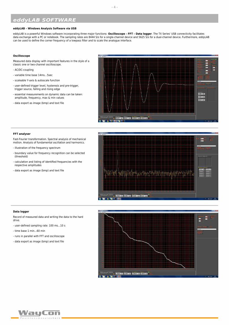
Oscilloscope
Measured data display with important features in the style of a
classic one or two-channel oscilloscope.
- AC/DC-coupling
- variable time base 14ms...5sec
- scaleable Y-axis & autoscale function
- user-defined trigger level, hysteresis and pre-trigger,
trigger source, falling and rising edge
- essential measurements on dynamic data can be taken:
amplitude, frequency, max & min values
- data export as image (bmp) and text file
eddyLAB – Windows Analysis Software via USB
eddyLAB is a powerful Windows software incorporating three major functions: Oscilloscope – FFT – Data logger. The TX Series' USB connectivity facilitates
data exchange with a PC or notebook. The sampling rates are 8444 S/s for a single-channel device and 5625 S/s for a dual-channel device. Furthermore, eddyLAB
can be used to define the corner frequency of a lowpass filter and to scale the analogue interface.
FFT analyser
Fast-Fourier transformation. Spectral analysis of mechanical
motion. Analysis of fundamental oscillation and harmonics.
- illustration of the frequency spectrum
- boundary value for frequency recognition can be selected
(threshold)
- calculation and listing of identified frequencies with the
respective amplitudes
- data export as image (bmp) and text file
Data logger
Record of measured data and writing the data to the hard
drive.
- user-defined sampling rate: 100 ms...10 s
- time base 1 min...60 min
- runs in parallel with FFT and oscilloscope
- data export as image (bmp) and text file

TECHNICAL DATA - PROBES
- 5 -
Probe T05 T2 T3 T4 T5 T10
range [mm] 0...0.5 0...2 0...3 0...4 0...5 0...10
range extended [mm] * 1 2.5 4 5 7 12
housing size ø5 ø8 ø12 ø14 ø18 ø30
offset gap (blind range) < 0.1 mm
linearity ±0.15% of range
resolution reg. corner frequency [% FS]** dependent on the distance (see resolution diagram on page 7), valid for middle of range
10 Hz 0.006 0.01 0.006 0.007 0.007 0.006
100 Hz 0.008 0.015 0.008 0.008 0.007 0.007
1 kHz 0.021 0.035 0.021 0.014 0.014 0.015
10 kHz 0.075 0.061 0.040 0.033 0.047 0.045
35 kHz 0.101 0.088 0.078 0.064 0.075 0.078
temperature range sensor -60...185 °C
temperature coefficient sensor dependent on distance (see temperature coefficient diagram on page 7)
sensor cable PTFE-COAX ø1.8 mm
cable length
min. bend radius static/dynamic 10/25 mm 15/37 mm
temperature range cable -55...+200 °C
connection BNC connector / optional SMB connector
protection class IP68
vibration 20 g, DIN EN 60068-2-6
shock 100 g / 6 ms, DIN EN 60068-2-27
check resistance [Ω] 6 8 9 12 12 9
housing material
* linearity and resolution are not valid for extended measurement ranges
** 98.5% confidence interval (confidence limit), middle of range as % of range. Resolution dependent on the distance (see „Resolution and Temperature“ on page 7)
ø2,5 mm (max. 2,7 mm)
standard length 3 m / 6 m, customised length up to 20 m
stainless steel 1.4305, sensor head PEEK (polyetheretherketon), FPM bend protection
Cable configuration
By default the probes have a BNC plug for the connection at the eddy current basic module. Optionally the probes are equipped with a SMB connector. The SMB
connection is either performed as BNC-SMB adapter (Version 1) or as a SMB-COAX cable extension (Version 2).
Please note:
The SMB connectors have beryllium copper contacts. The connector housing is gold plated and has an outer diameter of 6.5mm. This facilitates the installation in
particular with narrow conditions (Version 1). If the cable is durably affixed it might be desirable only to remove the probe from the entire cable (Version 2).
It is recommended to avoid unnecessary connections within the cable as it increases the probability of failure due to environmental influences such as wetness, dirt,
aggressive media, massive vibration or shock.
Standard version
- probe with BNC connector- cable length 3 m (standard)*
Version 1
- probe with SMB connector- cable length 3 m (standard)*- BNC-SMB adapter for eddy current basic module
Version 2
- probe with SMB connector- cable length 3 m (standard)*- additional extension cable SMB-KOAX with cable length 3 or 6 m*. SMB connector to BNC connector.
*customised cable length up to 20 m in total

TECHNICAL DATA – EDDY CURRENT BASIC MODULE
- 6 -
EddyCurrent-Basic Module TX1 TX2
channels 1 channel 2 channel
operating temperature range -40...+50 °C
storage temperature range -40...+85 °C
humidity 95 % (no condensation)
vibration 5 g, DIN EN 60068-2-6
shock 15 g / 11 ms, DIN EN 60068-2-27
protection class IP40
housing anodised aluminium with plastic frame and rubber feet, stackable
housing size L x W x H 197 x 115 x 49 mm
weight 668 g 685 g
Supply
Supply Voltage 10,5...36 VDC Wide Input
current consumption 145 mA (24 V), 260 mA (12 V), 300 mA (10.5 V) 180 mA (24 V), 300 mA (12 V), 380 mA (10.5 V)
power on peek current 350 mA (24V), 470 mA (10,5V), < 30 ms
reverse polarity protection yes
protection circuit bipolar suppressor diode 36V / polyfuse 0.5A
isolation voltage min. 1 kV
Analog output
output signals 0...10 V / 0...5 V / ±5 V / 0...20 mA / 4...20 mA
dynamic / sampling rate 124 kS/s 70 kS/s
dyn. / samp. with simultaneous USB usage 76 kS/s 45 kS/s
filter corner frequency 10 Hz / 100 Hz / 1 kHz / 10 kHz / 35 kHz (-3 dB)
max. working resistance (current output) < 400 Ohm
scalability of output signal scalability 100...8% of range (eddyLAB software)
temperature coefficient electronic -0.025 %/K
switching-on delay (boot-time) 3,1 s
switching-on drift < 1% (see diagram)
connection 1 x BNC female connector 2 x BNC female connector
output protection circuit polyfuse 50mA
General data and industrial standards
electromagnetic compatibility EN 61326-1 / EN 55011
RoHS appropriate standard 2002/95/EG
MTBF EN 61709, > 360.000 h
customs declaration number 90318034 country of origin Germany

RESOLUTION AND TEMPERATURE
- 7 -
Resolution nm...µm
The probe's resolution depends on the selected corner frequency and the
actual position. The best resolution is achieved within the first 50% of the
measurement range.
The following charts illustrate the resolution as a function of the position
(normalised) and the corner frequency. Low corner frequencies and positions
close to the target result in high resolutions.
Temperature coefficient TC
The temperature coefficient has a severe impact on the precision and in particular the repeatability of measurements when exposed to temperature variation.
WayCon probes have a remarkable temperature characteristic – the temperature coefficient is almost zero over wide ranges of temperature. The following charts
document the temperature coefficient as a function of the actual temperature and the position. The best temperature behaviour is achieved at 50% of the
measurement range. The temperature coefficient is evaluated within the extreme temperature range of -60...+180 °C.

PROPERTIES
- 8 -
Device drift after power-on
For highly precise measurements the device drift after power-on has to be
considered. The entire device drift is <1 % of measurement range.
~ 0.1 % of MR at 30 min. warm up
~ 0.2 % of MR at 20 min. warm up
~ 0.4 % of MR at 10 min. warm up
~ 0.8 % of MR without warm up
Frequency response
The TX Series contains a hardware filter with a corner frequency of 50 kHz in
its signal path. Additionally five user selectable software filters can be set. The
chart illustrates the respective characteristic. Lowering the corner frequency
increases the resolution. Note that higher frequencies will appear attenuated.
Zero TC measurements – Procedure:
The exceptional temperature behaviour of our probes allows zero TC
measurements. That means the position won't be affected by temperature
effects. Consider the following five aspects:
1) Only the probe is exposed to temperature.
2) The probe cable must be located predominantly outside of the
temperature-influenced measurement point and must not be laid on parts of
machines, etc., subject to temperature fluctuations. Consider this for
installation.
3) The eddy current basic module must be placed outside any temperature
influence or variation. The device must be powered 60 min before
measurements commences.
4) The measurement has to be taken in middle of the entire measurement
range.
5) The zero TC effect is only valid for temperatures on the zero TC line with
same positive and negative area (see chart).
All of our probes are tested and calibrated before shipping. The calibration is based on 50 positions. Every probe has a unique setup – therefore the probes may not interchanged among different drivers.
The certificate of calibration contains the measured and reference data, the
sensitivity, the target material and the linearity as a chart.
The certificate of calibration is provided as standard – but it is also available
subsequently.
Target – material
Eddy current measurements depend on the target's conductivity and
permittivity. The default material for factory calibration is steel of type
16MnCr5. Calibration is also possible with other conductive material such as
aluminium, titanium, carbon fibre etc.
The following list shows available material for calibration. If you desire to use a
different material we recommend to provide a probe (50x50mm) for
calibration.
CALIBRATION
materials to choose from for calibration
16MnCr5 1.2379 AlMgSi0,5
42CrMo4 1.2738 AlMg4,5Mn
St52 1.4301
C45E 1.4305 9SMn28k
AlMgCuPb
also eligible for calibration: zinc plate, titanium, carbon fiber
example: zero TC at 0 °C, 60 °C and 155 °C
+
- -

Supply via a 4-pole M12 plug connector (socket)
View of the unit and the soldering side of the mating connector.
Pin 1 (brown) = +V (supply 10.5...36 VDC)
Pin 3 (blue) = GND
For connecting the power, shielded cables in various lengths are available (see
accessories).
Please use only shielded supply cables and set the screen on one side
(to avoid earth loops)!
USB / CAN / CONNECTION
- 9 -
CAN bus (will be available soon)
The eddy current basic module also provides a CAN-bus interface (controller
area network).
- data transfer rate 1 MBit, standard and extended-identifier
- networking of many devices with minimal wiring effort
- highly reliable data transfer over wide ranges – ideal for applications with
many devices (consider dynamics)
- economisation of analogue measuring equipment (analog-to-digital
converter)
Wiring is achieved with a CAN-bus cable. The first and the last device on a
CAN bus must be terminated.
When communicating via CAN bus, the position can be read and filters can be
set.
Digital IN OUT/CAN (D-SUB 9-pole MALE)
PIN Name
1 EXT OPTO OUT 1
2 CAN L
3 CAN GND
4 EXT IN 1
5 EXT IN 2
6 IN GND
7 CAN H
8 EXT OPTO OUT 2
9 CAN GND
Description
digital output I/O 1
CAN low signal
CAN ground
digital input I/O 1
digital input I/O 2
ground I/O
CAN high signal
digital output I/O 2
CAN ground
M12 plugsupply
CAN busand Opto I/O
USB connection
Front of unit Rear of unit
USB
The eddy current basic module provides a USB port (USB 2.0 High Speed).
- data transfer rate 5 MBit
- sampling rate 38 kS/s (single channel), 22,5 kS/s (dual channel)
- device configuration (filter, scale, CAN bus)
- data exchange with a PC or notebook via eddyLAB Windows software or via
protocol
Sampling rates TX1 TX2
Analogue without USB
Analogue with USB
USB
124 kS/s 70 kS/s
76 kS/s 45 kS/s
38 kS/s 22.5 kS/s
probe 1
output 1
output 2
probe 2

The probe T05 is only available in a shielded version.
T05-G-KA-M805 T05-G-KA-VL10-M805T05-G-KAType T05
TECHNICAL DRAWINGS
- 10 -
Type T2
T2-G-KR
T2-G-KA-VK23 (short version)
T2-S-KA
T2-M14-KA-PR
T2-S-KR
T2-G-KR-VK7 (short version)
T2-G-M12-KA-110-LANG
T2-G-KA T2-G-KA-VL20
T05-G-KA-VK10Material: 1.4404

T3-FL-M1205-KR (flange version)
T3-S-KR T3-G-KA
T3-G-KA-VL10T3-G-KR
Type T4
TECHNICAL DRAWINGS
- 11 -
Type T10
Type T3
T5-G-KR-VL10
Type T5

Cable for power supply with mating connector M12 straight and angled - K4P
Cable with straight connector:
K4P2M-S-M12 2 m
K4P5M-S-M12 5 m
K4P10M-S-M12 10 m
BNC measurement line for the analogue output (Multi-Contact)
XLSS-58
Touch-safe coaxial measurement line. BNC connectors on both ends. Connectors have nickel plated shields and gold
plated pins.
length 2 m, temperature range -10...+70 °C
capacity 219 pF, inductance 680 nH, wave impedance 50 Ω
XLAM-446/SC
Highly flexible, entirely shielded measurement line. Touch-safe BNC connector on one end and two stackable Ø 4
mm connectors on the other end.
length 1.6 m, temperature range -10...+70 °C
capacity 240 pF, inductance 1000 nH
Cable with angled connector:K4P2M-SW-M12 2 mK4P5M-SW-M12 5 mK4P10M-SW-M12 10 m
ACCESSORIES
- 12 -
eddyLAB
Powerful Windows software incorporating three major functions:
Oscilloscope – FFT – Data logger (page 3).
Delivery contents: software-CD, gold-plated USB cable, dual shields
incl. 2 ferrites, length 1.8 m
Rail-power supply 24 VDC
PS-100-240AC/24DC/1.3
Extra narrow power supply - only 22.5 mm wide. Reliable start-up of several eddy current basic devices is guaranteed by a 100%
power boost.
Reliability is also achieved on difficult global networks. The supply will remain stable even if transient or static voltage failure occurs.
Well dimensioned capacitors bypass power failures of more than 20 ms.
nominal input voltage 100-240 VAC, 45-65 Hz
output voltage 24 VDC
output current 1.3 A (max. 1.6 A)
temperature range -25...+60 °C
power failure bypassing > 110 ms (230 VAC)
efficiency > 85%
protection class IP20
Cable extension SMB-KOAX
Additional extension accordingly to option 2 (see page 5 below). SMB connector to BNC connector.
3 m length: SMB-KOAX-3M
6 m length: SMB-KOAX-6M
Note: for probes with SMB connectors only. The probe is calibrated with an extension that can be
additionally ordered. Optional operation without extension is then no longer possible.

Electrical installation
Choose a dry location, preferably with a stable temperature for the electrical installation (eddy current basic module) such as electrical cabinets,
terminal boxes, housing, etc.
Connect the supply line, probe lines and output lines. Please ensure that all supply and signal lines are laid separately from energy-carrying lines such as supply and
discharge lines from converters and drives, lines from ovens and synchronised appliances or generator lines, etc., in order to avoid malfunctions in the signal
behaviour.
Please use shielded supply lines only and apply the shield to one side to avoid earth loops.
Please observe the correct assignment of the probes to the respective basic modules and channels. Each individual channel is aligned by the probe as a pair.
Probe installation
Firstly, install the probe at the relevant installation location and affix the probe using jam nuts or clamp mechanisms. After you have installed the probe, lay the
cable. Ensure that the cable is laid without dents and it is not placed under stress. After you have laid the cable into place, do not turn the probe out of the thread, so
as to prevent cable damage arising from stress. Secure excess probe cable as far away from temperature influences as possible, i.e. away from electronics. Never
shorten the probe cable!
Please note that the probe head must be kept free from neighbouring metallic objects. In order to avoid attenuation of the measuring system, the following locations
must not be impaired. In the case of installation into non-metallic and non-conductive materials, this is not necessary.
1) Installation with 45° countersinking. The diameter of the countersinking must be at least three times greater than the probe head diameter.
2) Installation with cylindrical countersinking. The diameter of the cylindrical countersinking must be at least 2-3 times greater than the probe head diameter. The
projection of the probe cylindrical bottom: approx. three times the size of the measurement area; however, of at least the length of the PEEK head.
3) + 4) Installation into boards or metal with front or rear jam nut. Ideally, ensure there is an additional thread projection of approx. 3 mm to the board or the jam
nut. Please note that thin-walled holders can oscillate or vibrate, and the holder’s own frequency can interfere with the measurement result.
If these locations cannot be kept free of impairment as recommended, it is recommended that a ferrite-shielded probe or a customer-specific linearisation is used.
Ferrite-shielded probes are available upon request.
Recommended pressure-tight installation
Some standard units can be installed in a pressure-tight manner to withstand system pressure of up to 50 bar by using a PEEK connector with O rings (see the image
on the right). In the case of greater pressure areas, we can produce pressure-tight units as required.
INSTALLATION
- 13 -
1 2 3 4
Please turn over

A B C D
Object size and the eddy current measurement field
The eddy current measurement field (illustrated in red) is emitted elliptically from the probe level, and is greater than the probe head in terms of its spatial
expansion. Therefore, for standard-calibrated probes a two-dimensional object surface with a probe head diameter 2-3 times greater than this is necessary for
measurement. If the object is too small, only a part of the measurement field enters the material, and the output signal becomes larger. If the diameter is too small,
the object appears to be further away from the sensor. A similar effect takes place in the case of round objects.
However, if other metallic objects force their way into the measurement field (e.g. laterally), the output signal is reduced due to the additional object. The actual
object appears to be closer to the probe. If this signal alteration is not desired, we can provide customer-specific linearisation for such applications. In this case, the
probe is calibrated directly with the object provided. The measurement area and the linearity are thus re-introduced into the specified area. The object (shape,
material) is documented in the calibration document.
The following provides an overview of various geometric object properties:
A) Optimum object surface, preferably 2-3 times greater than the probe head diameter. The measurement field is captured by the object entirely.
B) Reduced object surface, a part of the measurement field remains untouched by the object. The probe displays a greater distance signal than the actual distance.
The measurement area is reduced in size. Lateral object movements can influence the distance signal. We can perform a customer-specific calibration in order to
correct the measurement area and linearity.
C) Large round objects (diameter > 8 x probe head diameter) such as cranks or shafts can be captured without significant signal alterations. The probe outputs the
medium distance via the captured surface. The measurement area reduces in size by < 10%. To correct this, an optional customer-specific calibration can be
performed. For example: shaft diameter > 8 x probe head diameter measured area reduction < 10%, linearity < 0.5% of the measured area.
D) Small round objects such as shafts or wire (diameter < 2 x probe head diameter) can only be captured with a significantly smaller measurement area, insofar as
customer-specific calibration has not taken place. For example: shaft diameter < 2 x probe head diameter reduction in the measurement area of ~ 25%, linearity ~
1%. In this case, we recommend that we perform customer-specific calibration.
Metallic objects in the measurement field
Please note that metallic objects such as screw heads, bolts, etc., located in the measurement field in both a radial and axial direction (or which cross the
measurement field during rotation) can become disturbance variables in the signal.
INSTALLATION
- 14 -

• Never shorten the probe‘s coaxial cable. The probe, cable and electronic system
form a coordinated oscillating circuit.
• Lay the cable so that it is protected and avoid running it along objects with sharp
edges. A cable that has been squashed or damaged in another manner can tamper
with the signal or render the probe unusable.
PRECAUTIONS
- 15 -
PROBE ORDER CODE
BASE MODULE ORDER CODE
Measurement range [mm]
0...0.5
0...2
0...3
0...4
0...5
0...10
05
2
3
4
5
10
Design
shaft
thread
S
G
1 channel
2 channel
1
2
Power supply
9...36 VDC 24
Analogue output per channel
0...20 mA
4...20 mA
0...10 V
0...5 V
±5 V
020A
420A
10V
5V
±5V
T
Resolution
16 bit AD/ DA 16
TX
• Please note that the sensors have been aligned with the electronic system. The alignment can be
found in the calibration record or on the label on the unit, identified by the serial number. Do not
switch the channels.
• Avoid placing the cable under tensile or torsional stress. Never turn the probes in the holders
inwards or outwards without first loosening the fastenings.
• Observe the minimum bend radius for dynamic and static installation stated in the data sheet. Avoid
kinks in the line.
• Protect the plug connections in the coaxial line against humidity and wetness.
axial cable output
radial cable output (not for model T4 and T10)
KA
KR
Options
cable length 3 meter (standard)
cable length 6 meter
cable length 9 meter
cable length 12 meter
cable length 15 meter
probe with SMB connector
shielded probe
-
6M
9M
12M
15M
SMB
SHIELDED
Type
standard
probe with options
-
O
Please find all versions on page 10 to 11.

ACCESSORIES
Cologne Office
Auf der Pehle 1
50321 Brühl
Tel. +49 (0)2232 56 79 44
Fax +49 (0)2232 56 79 45
Head Office
Mehlbeerenstr. 4
82024 Taufkirchen
Tel. +49 (0)89 67 97 13-0
Fax +49 (0)89 67 97 13-250
WayCon Positionsmesstechnik GmbH
email: [email protected]
internet: www.waycon.de
Subject to change without prior notice.
- 16 -
OPTIONS
6M
9M
12M
15M
SHIELDED shielded probe
SMB probe with SMB connector
cable length 6 m
cable length 9 m
cable length 12 m
cable length 15 m
SMB-KOAX-3M BNC measurement cables for the analogue output
SMB-KOAX-6M XLSS-58
BNC/SMB adapter BNC/SMB for connection to TX module XLAM-446/SC
Power supply cable with M12 mating connector Windows-Software for USB
K4P2M-S-M12
K4P5M-S-M12 Power supply units
K4P10M-S-M12 PS-100-240AC/24DC/1.3
K4P2M-SW-M12 PS-100-240AC/24DC/4
K4P5M-SW-M12 FW7662/12
K4P10M-SW-M12
extension cable for SMB connector 3 m
extension cable for SMB connector 3 m BNC into BNC, 2 m
BNC into ø4 mm curved, 1.6 m
2 m, straight connector eddyLAB software CD, USB cable 1.8 m
5 m, straight connector
10 m, straight connector 24 VDC, 1.3 A / max. 1.6 A (DIN rail mounting)
2 m, angular connector 24 VDC, 4 A / max. 5 A (DIN rail mounting)
5 m, angular connector 12 VDC ±5%, 500 mA (power supply for wall outlet)
10 m, angular connector
CABLE CONFIGURATION (see page 5)
Standard
probe with BNC connector
Version 1: probe with SMB connector and BNC/SMB adapter
please order: Option SMB + BNC/SMB (accessory)
Version 2: probe with SMB connector and extension cable for SMB connector
please order for 3 m extension cable: Option SMB + SMB-KOAX-3M (accessory)
please order for 6 m extension cable: : Option SMB + SMB-KOAX-6M (accessory)