Embed Size (px)
Citation preview
�/�2
Eddy Current DynoFrein à courant de Foucault
Water cooled Eddy current dynamometerA range of products rated from 5 to 3200 kw.
1,2,3 or 4 rotor technology.Full Digital control panel. Extended safeties conceptStand alone solution
EddyCurrentDyno_UKP_08_14
2/�2
ROTRONICS
ROTRONICS, specialists in engine test beds, offers a range of industrial Eddy current dynamometers.
OPERATING PRINCIPLE
`The brake allows application of a load to an engine undergoing dynamometer testing for measurement of its speed and torque.The brake essentially comprises a rotor and a stator.The stator is mounted on the chassis and circumferential ly retained. Rotational force acting upon it is measured by a load cell. The stator also incorporates electrical windings and ducts for water cooling.The rotor turns inside the stator where it is subjected to a magnetic field generated by the electrical windings. When the rotor turns, it cross the lines of force and induces Eddy currents. These currents generate forces which oppose the movement that gave rise to them. The force of the engine is then transmitted to the stator, and measured by the load cell. Knowing the magnitude of the lever arm and the rotational speed, the engine’s torque can therefore be measured.
The mechanical energy absorbed by the brake is transformed into heat. The heat is removed by cooling water circulated through ducts within the stator. The cooling circuit is dimensioned in order to dissipate the heat energy produced when the dynamometer is running at its maximum power rating.
The speed of rotation is measured by a magneto-resistive sensor in association with an indexed wheel.
�/�2
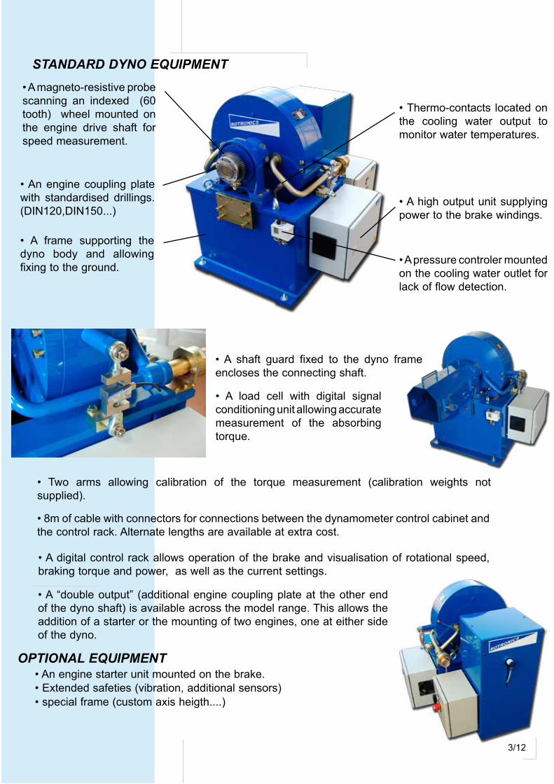
STANDARD DYNO EQUIPMENT
• A frame supporting the dyno body and allowing fixing to the ground.
• An engine coupling plate with standardised drillings.(DIN�20,DIN�50...)
• A magneto-resistive probe scanning an indexed (60 tooth) wheel mounted on the engine drive shaft for speed measurement.
• A pressure controler mounted on the cooling water outlet for lack of flow detection.
• A high output unit supplying power to the brake windings.
• Thermo-contacts located on the cooling water output to monitor water temperatures.
• A “double output” (additional engine coupling plate at the other end of the dyno shaft) is available across the model range. This allows the addition of a starter or the mounting of two engines, one at either side of the dyno.
OPTIONAL EQUIPMENT
• A digital control rack allows operation of the brake and visualisation of rotational speed, braking torque and power, as well as the current settings.
• A shaft guard fixed to the dyno frame encloses the connecting shaft.
• Two arms allowing calibration of the torque measurement (calibration weights not supplied).
• 8m of cable with connectors for connections between the dynamometer control cabinet and the control rack. Alternate lengths are available at extra cost.
• A load cell with digital signal conditioning unit allowing accurate measurement of the absorbing torque.
• An engine starter unit mounted on the brake. • Extended safeties (vibration, additional sensors) • special frame (custom axis heigth....)
�/�2
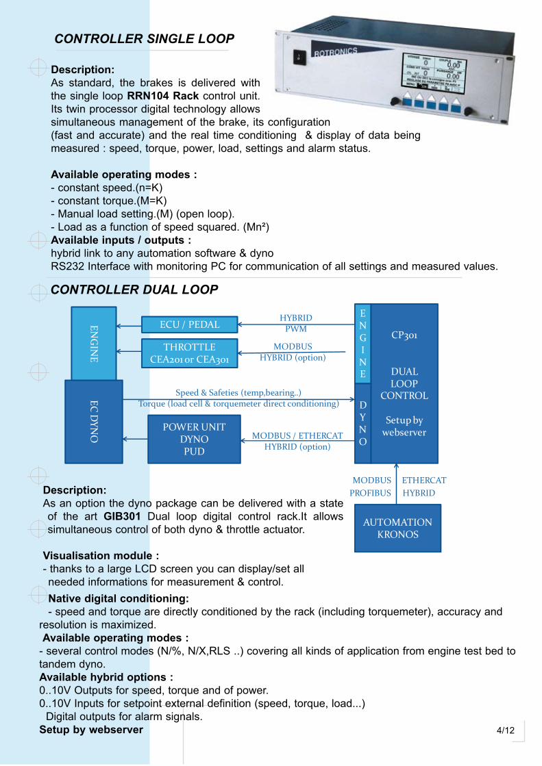
Description:As standard, the brakes is delivered with the single loop RRN104 Rack control unit.Its twin processor digital technology allows simultaneous management of the brake, its configuration (fast and accurate) and the real time conditioning & display of data being measured : speed, torque, power, load, settings and alarm status.
Available operating modes :- constant speed.(n=K)- constant torque.(M=K)- Manual load setting.(M) (open loop).- Load as a function of speed squared. (Mn²)Available inputs / outputs :hybrid link to any automation software & dyno RS2�2 Interface with monitoring PC for communication of all settings and measured values.
CONTROLLER SINGLE LOOP
Description:As an option the dyno package can be delivered with a state of the art GIB301 Dual loop digital control rack.It allows simultaneous control of both dyno & throttle actuator.
Visualisation module :- thanks to a large LCD screen you can display/set all needed informations for measurement & control.
CONTROLLER DUAL LOOP
ECD
YNO
ENG
INE
ECU / PEDAL
THROTTLECEA201 or CEA301
CP301
DUALLOOP
CONTROL
Setup bywebserverPOWER UNIT
DYNOPUD
Speed & Safeties (temp,bearing..)Torque (load cell & torquemeter direct conditioning)
ENGINE
DYNO
MODBUS / ETHERCATHYBRID (option)
MODBUSHYBRID (option)
HYBRIDPWM
AUTOMATIONKRONOS
MODBUS ETHERCATPROFIBUS HYBRID
Native digital conditioning:- speed and torque are directly conditioned by the rack (including torquemeter), accuracy and
resolution is maximized. Available operating modes :- several control modes (N/%, N/X,RLS ..) covering all kinds of application from engine test bed to tandem dyno.Available hybrid options :0..�0V Outputs for speed, torque and of power.0..�0V Inputs for setpoint external definition (speed, torque, load...) Digital outputs for alarm signals. Setup by webserver
5/�2
TEChNICAL SPECIfICATIONS
The indicated (cooling) water flow corresponds in a 20° rise in water temperature when operating the dyno at maximum power (typically max inlet temp �0°C, Max outlet 50°C) At this flow level there is a � Bar pressure drop across the dyno.
The dyno’s high speed bearings are oil lubricated.
Direction of rotation : reversible
Design of the cooling water input and output allows easy connection to the cooling water circuit (not supplied). The brake cooling circuit is completely watertight and operates under pressure. The cooling water circuit has no effect on brake hysteresis , which remains well with the stated accuracy.
Color : Blue (RAL 70�0) as standard, other colors available on demand.
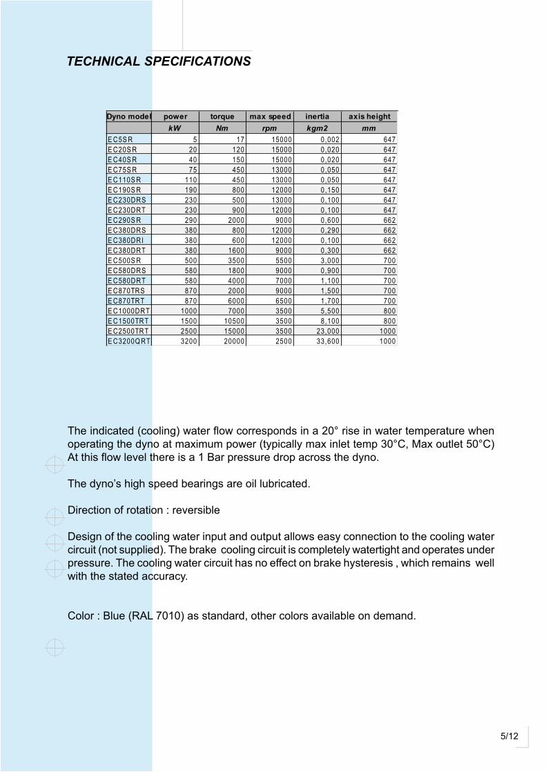
Dyno model power torque max speed inertia axis height TYPEkW Nm rpm kgm2 mm
E C5S R 5 17 15000 0,002 647 S RE C20S R 20 120 15000 0,020 647 S RE C40S R 40 150 15000 0,020 647 S RE C75S R 75 450 13000 0,050 647 S RE C110S R 110 450 13000 0,050 647 S RE C190S R 190 800 12000 0,150 647 S RE C230DRS 230 500 13000 0,100 647 DRSE C230DRT 230 900 12000 0,100 647 DRTE C290S R 290 2000 9000 0,600 662 S RE C380DRS 380 800 12000 0,290 662 DRSE C380DRI 380 600 12000 0,100 662 DRIE C380DRT 380 1600 9000 0,300 662 DRTE C500S R 500 3500 5500 3,000 700 S RE C580DRS 580 1800 9000 0,900 700 DRSE C580DRT 580 4000 7000 1,100 700 DRTE C870TRS 870 2000 9000 1,500 700 TRSE C870TRT 870 6000 6500 1,700 700 TRTE C1000DRT 1000 7000 3500 5,500 800 DRTE C1500TRT 1500 10500 3500 8,100 800 TRTE C2500TRT 2500 15000 3500 23,000 1000 TRTE C3200Q RT 3200 20000 2500 33,600 1000 Q RT

6/�2
Sin
gleR
otor
SR
TEC
hN
ICA
L C
hA
RA
CTE
RIS
TIC
S
Dyn
oty
pe
AB
CD
EF
GH
øI
J±2
øk
LM
NO
PQ
RS
TU
VW
X±4
Y±2
Za
bø
c(g
6)
ød
øe
øf
hW
eig
htkg
EC
20
-40
SR
370
43
04
80
62
070
82
353
64
716
23
G¾
“9
03
40
42
09
056
014
504
35
350
1815
02
5050
9,9
417
20
8,5
42
47
M8
74,5
89
1219
3
EC
75-1
10S
R4
00
46
051
06
5070
874
546
47
162
6G
1“9
04
60
540
90
68
014
504
00
44
018
150
32
510
19,7
452
22
66
257
M8
84
99
122
40
EC
190
SR
510
580
63
077
070
93
56
66
62
22
30
G1“
¼9
054
06
40
90
500
1450
38
954
018
150
375
1019
,759
12
95,
58
275
M10
101,
511
913
39
3
EC
29
0S
R6
30
69
074
08
80
7010
40
67
700
22
23
G1”
½9
06
60
760
90
90
013
503
87
64
018
150
40
510
19,7
700
350
82
,59
0M
1213
015
016
66
0
EC
500
SR
740
80
08
5010
30
90
124
22
88
00
22
49
,5G
2“
100
90
010
00
90
118
012
504
60
88
02
215
051
715
29
,68
65
43
2,5
82
,511
0M
1215
5,5
180
1611
50
Dyn
oT
ype
AB
CD
EF
GH
øI
J±2
øk
LM
NO
PQ
RS
TU
VW
X±4
Y±2
Za
bø
c(g
6)
ød
øe
øf
hW
eig
htkg
EC
23
0D
RS
518
578
62
876
870
874
190
64
716
17G
1”½
90
46
054
09
06
80
1450
40
04
40
1815
03
25
1019
,757
02
26
118
62
57M
88
49
912
38
5
EC
38
0D
RS
66
273
278
29
22
709
35
190
66
22
23
1G
2”
90
540
64
09
078
014
503
89
540
1815
03
7710
19,7
743
29
5,5
152
82
75M
1010
1,5
119
136
30
EC
38
0D
RI
66
273
278
29
22
709
35
190
66
22
23
1G
2”
90
540
64
09
078
014
503
89
540
1815
03
7710
19,7
743
29
5,5
152
82
75M
1010
1,5
119
136
30
EC
580
DR
S75
48
148
64
100
470
104
017
070
02
22
3G
2”
90
66
076
09
09
25
1350
38
76
40
1815
04
1515
29
,68
24
32
2,5
179
82
,59
0M
1213
015
016
1050
EC
23
0D
RT
562
63
26
82
82
270
874
190
64
716
30
G1”
½9
04
60
540
90
68
014
504
00
44
018
150
32
510
19,7
64
12
51,5
138
82
75M
1010
1,5
119
134
35
EC
38
0D
RT
732
80
28
529
92
709
35
190
66
22
22
1G
2“
90
540
64
09
078
014
503
89
540
1815
03
7710
19,7
80
23
17,5
167
82
,59
0M
1213
015
016
735
EC
580
DR
T79
98
60
910
1050
7010
40
7070
02
24
9G
2“
90
66
076
09
09
25
1350
38
76
40
1815
04
1515
29
,69
26
36
12
04
82
,511
0M
1215
5,5
180
1611
60
EC
100
0D
RT
103
411
1411
84
142
412
012
42
90
80
02
757
G2
”½10
09
80
108
09
013
20
22
502
90
88
02
72
00
560
20
39
,411
82
46
62
508
314
0M
18x1
.52
182
503
02
30
0
Dyn
oty
pe
AB
CD
EF
GH
øI
J±2
øk
LM
NO
PQ
RS
TU
VW
X±4
Y±2
Za
bø
c(g
6)
ød
øe
øf
hW
eig
htkg
??
??
745
815
86
510
45
90
93
4,5
22
26
62
22
29
,5G
2”½
90
540
66
013
08
00
1350
38
954
018
150
377
1019
,78
25,
52
60
,515
212
275
M10
101,
511
913
90
0
EC
870
TR
S9
33
99
310
43
122
39
010
40
172
700
22
23
G2
”½9
06
60
760
130
90
013
503
87
64
018
150
415
152
9,6
100
33
22
,517
98
2,5
110
M12
155,
518
016
1450
EC
870
TR
T10
03
106
411
1412
94
90
104
070
700
22
49
G2
”½9
06
60
760
130
90
013
503
87
64
018
150
415
152
9,6
113
03
61
20
48
2,5
110
M16
155,
518
03
016
00
EC
150
0T
RT
128
413
64
143
416
7412
012
42
90
80
02
757
G3
”10
09
80
108
013
013
20
20
00
46
08
80
27
20
056
02
03
9,4
143
24
66
250
83
140
M18
*1,5
218
26
03
03
30
0
EC
250
0T
RT
1417
149
715
67
186
715
015
60
210
100
02
79
112
52
00
1150
130
013
016
00
24
00
520
850
37
20
06
35
20
39
,416
38
523
29
68
+86
175
M2
0*2
Ø2
02
45
28
53
055
00
Dyn
oty
pe
AB
CD
EF
GH
øI
J±2
øk
LM
NO
PQ
RS
TU
VW
X±4
Y±2
Za
bø
c(g
6)
ød
øe
øf
hW
eig
htkg
EC
32
00
QR
T17
1317
93
186
32
163
150
1 5 6
02
1010
00
27
91
125
20
011
5013
00
130
160
02
40
052
08
503
72
00
64
72
03
9,4
193
452
32
96
8+8
617
5M
20
*2Ø
20
24
52
85
30
760
0
CW
CC
WC
W
Sen
s d
e ro
tati
on
Ro
tati
on
Dir
ecti
on
Cap
teu
r de
forc
eLo
ad c
ell
Entr
ée d
’eau
Wat
er In
let
Sort
ie d
’eau
Wat
er O
utl
et
Pres
sost
atD
iffer
enti
al p
ress
ure
sw
itch
An
nea
u d
e le
vag
eLi
ftin
g
(Nb
alé
sag
e)(N
b h
ole
s)B
rid
e d
’acc
ou
ple
men
tEn
gin
e C
ou
plin
g F
lan
ge
Cap
teu
r Vit
esse
Pick
up
7/�2
Dou
bleR
otor
DR
TEC
hN
ICA
L C
hA
RA
CTE
RIS
TIC
S CC
WC
W
An
nea
u d
e le
vag
eLi
ftin
g
Sen
s d
e ro
tati
on
Ro
tati
on
Dir
ecti
on
Sort
ie d
’eau
Wat
er O
utl
et
Pres
sost
atD
iffer
enti
al p
ress
ure
sw
itch
Cap
teu
r de
forc
eLo
ad c
ell
Entr
ée d
’eau
Wat
er In
let
(Nb
alé
sag
es)
(Nb
ho
les)
Bri
de
d’a
cco
up
lem
ent
Eng
ine
Co
up
ling
Fla
ng
e
Cap
teu
r Vit
esse
Pick
up
Dyn
oty
pe
AB
CD
EF
GH
øI
J±2
øk
LM
NO
PQ
RS
TU
VW
X±4
Y±2
Za
bø
c(g
6)
ød
øe
øf
hW
eig
htkg
EC
20
-40
SR
370
43
04
80
62
070
82
353
64
716
23
G¾
“9
03
40
42
09
056
014
504
35
350
1815
02
5050
9,9
417
20
8,5
42
47
M8
74,5
89
1219
3
EC
75-1
10S
R4
00
46
051
06
5070
874
546
47
162
6G
1“9
04
60
540
90
68
014
504
00
44
018
150
32
510
19,7
452
22
66
257
M8
84
99
122
40
EC
190
SR
510
580
63
077
070
93
56
66
62
22
30
G1“
¼9
054
06
40
90
500
1450
38
954
018
150
375
1019
,759
12
95,
58
275
M10
101,
511
913
39
3
EC
29
0S
R6
30
69
074
08
80
7010
40
67
700
22
23
G1”
½9
06
60
760
90
90
013
503
87
64
018
150
40
510
19,7
700
350
82
,59
0M
1213
015
016
66
0
EC
500
SR
740
80
08
5010
30
90
124
22
88
00
22
49
,5G
2“
100
90
010
00
90
118
012
504
60
88
02
215
051
715
29
,68
65
43
2,5
82
,511
0M
1215
5,5
180
1611
50
Dyn
oT
ype
AB
CD
EF
GH
øI
J±2
øk
LM
NO
PQ
RS
TU
VW
X±4
Y±2
Za
bø
c(g
6)
ød
øe
øf
hW
eig
htkg
EC
23
0D
RS
518
578
62
876
870
874
190
64
716
17G
1”½
90
46
054
09
06
80
1450
40
04
40
1815
03
25
1019
,757
02
26
118
62
57M
88
49
912
38
5
EC
38
0D
RS
66
273
278
29
22
709
35
190
66
22
23
1G
2”
90
540
64
09
078
014
503
89
540
1815
03
7710
19,7
743
29
5,5
152
82
75M
1010
1,5
119
136
30
EC
38
0D
RI
66
273
278
29
22
709
35
190
66
22
23
1G
2”
90
540
64
09
078
014
503
89
540
1815
03
7710
19,7
743
29
5,5
152
82
75M
1010
1,5
119
136
30
EC
580
DR
S75
48
148
64
100
470
104
017
070
02
22
3G
2”
90
66
076
09
09
25
1350
38
76
40
1815
04
1515
29
,68
24
32
2,5
179
82
,59
0M
1213
015
016
1050
EC
23
0D
RT
562
63
26
82
82
270
874
190
64
716
30
G1”
½9
04
60
540
90
68
014
504
00
44
018
150
32
510
19,7
64
12
51,5
138
82
75M
1010
1,5
119
134
35
EC
38
0D
RT
732
80
28
529
92
709
35
190
66
22
22
1G
2“
90
540
64
09
078
014
503
89
540
1815
03
7710
19,7
80
23
17,5
167
82
,59
0M
1213
015
016
735
EC
580
DR
T79
98
60
910
1050
7010
40
7070
02
24
9G
2“
90
66
076
09
09
25
1350
38
76
40
1815
04
1515
29
,69
26
36
12
04
82
,511
0M
1215
5,5
180
1611
60
EC
100
0D
RT
103
411
1411
84
142
412
012
42
90
80
02
757
G2
”½10
09
80
108
09
013
20
22
502
90
88
02
72
00
560
20
39
,411
82
46
62
508
314
0M
18x1
.52
182
503
02
30
0
Dyn
oty
pe
AB
CD
EF
GH
øI
J±2
øk
LM
NO
PQ
RS
TU
VW
X±4
Y±2
Za
bø
c(g
6)
ød
øe
øf
hW
eig
htkg
??
??
745
815
86
510
45
90
93
4,5
22
26
62
22
29
,5G
2”½
90
540
66
013
08
00
1350
38
954
018
150
377
1019
,78
25,
52
60
,515
212
275
M10
101,
511
913
90
0
EC
870
TR
S9
33
99
310
43
122
39
010
40
172
700
22
23
G2
”½9
06
60
760
130
90
013
503
87
64
018
150
415
152
9,6
100
33
22
,517
98
2,5
110
M12
155,
518
016
1450
EC
870
TR
T10
03
106
411
1412
94
90
104
070
700
22
49
G2
”½9
06
60
760
130
90
013
503
87
64
018
150
415
152
9,6
113
03
61
20
48
2,5
110
M16
155,
518
03
016
00
EC
150
0T
RT
128
413
64
143
416
7412
012
42
90
80
02
757
G3
”10
09
80
108
013
013
20
20
00
46
08
80
27
20
056
02
03
9,4
143
24
66
250
83
140
M18
*1,5
218
26
03
03
30
0
EC
250
0T
RT
1417
149
715
67
186
715
015
60
210
100
02
79
112
52
00
1150
130
013
016
00
24
00
520
850
37
20
06
35
20
39
,416
38
523
29
68
+86
175
M2
0*2
Ø2
02
45
28
53
055
00
Dyn
oty
pe
AB
CD
EF
GH
øI
J±2
øk
LM
NO
PQ
RS
TU
VW
X±4
Y±2
Za
bø
c(g
6)
ød
øe
øf
hW
eig
htkg
EC
32
00
QR
T17
1317
93
186
32
163
150
1 5 6
02
1010
00
27
91
125
20
011
5013
00
130
160
02
40
052
08
503
72
00
64
72
03
9,4
193
452
32
96
8+8
617
5M
20
*2Ø
20
24
52
85
30
760
0
8/�2
Trip
leR
otor
TR
TEC
hN
ICA
L C
hA
RA
CTE
RIS
TIC
S
Dyn
oty
pe
AB
CD
EF
GH
øI
J±2
øk
LM
NO
PQ
RS
TU
VW
X±4
Y±2
Za
bø
c(g
6)
ød
øe
øf
hW
eig
htkg
EC
20
-40
SR
370
43
04
80
62
070
82
353
64
716
23
G¾
“9
03
40
42
09
056
014
504
35
350
1815
02
5050
9,9
417
20
8,5
42
47
M8
74,5
89
1219
3
EC
75-1
10S
R4
00
46
051
06
5070
874
546
47
162
6G
1“9
04
60
540
90
68
014
504
00
44
018
150
32
510
19,7
452
22
66
257
M8
84
99
122
40
EC
190
SR
510
580
63
077
070
93
56
66
62
22
30
G1“
¼9
054
06
40
90
500
1450
38
954
018
150
375
1019
,759
12
95,
58
275
M10
101,
511
913
39
3
EC
29
0S
R6
30
69
074
08
80
7010
40
67
700
22
23
G1”
½9
06
60
760
90
90
013
503
87
64
018
150
40
510
19,7
700
350
82
,59
0M
1213
015
016
66
0
EC
500
SR
740
80
08
5010
30
90
124
22
88
00
22
49
,5G
2“
100
90
010
00
90
118
012
504
60
88
02
215
051
715
29
,68
65
43
2,5
82
,511
0M
1215
5,5
180
1611
50
Dyn
oT
ype
AB
CD
EF
GH
øI
J±2
øk
LM
NO
PQ
RS
TU
VW
X±4
Y±2
Za
bø
c(g
6)
ød
øe
øf
hW
eig
htkg
EC
23
0D
RS
518
578
62
876
870
874
190
64
716
17G
1”½
90
46
054
09
06
80
1450
40
04
40
1815
03
25
1019
,757
02
26
118
62
57M
88
49
912
38
5
EC
38
0D
RS
66
273
278
29
22
709
35
190
66
22
23
1G
2”
90
540
64
09
078
014
503
89
540
1815
03
7710
19,7
743
29
5,5
152
82
75M
1010
1,5
119
136
30
EC
38
0D
RI
66
273
278
29
22
709
35
190
66
22
23
1G
2”
90
540
64
09
078
014
503
89
540
1815
03
7710
19,7
743
29
5,5
152
82
75M
1010
1,5
119
136
30
EC
580
DR
S75
48
148
64
100
470
104
017
070
02
22
3G
2”
90
66
076
09
09
25
1350
38
76
40
1815
04
1515
29
,68
24
32
2,5
179
82
,59
0M
1213
015
016
1050
EC
23
0D
RT
562
63
26
82
82
270
874
190
64
716
30
G1”
½9
04
60
540
90
68
014
504
00
44
018
150
32
510
19,7
64
12
51,5
138
82
75M
1010
1,5
119
134
35
EC
38
0D
RT
732
80
28
529
92
709
35
190
66
22
22
1G
2“
90
540
64
09
078
014
503
89
540
1815
03
7710
19,7
80
23
17,5
167
82
,59
0M
1213
015
016
735
EC
580
DR
T79
98
60
910
1050
7010
40
7070
02
24
9G
2“
90
66
076
09
09
25
1350
38
76
40
1815
04
1515
29
,69
26
36
12
04
82
,511
0M
1215
5,5
180
1611
60
EC
100
0D
RT
103
411
1411
84
142
412
012
42
90
80
02
757
G2
”½10
09
80
108
09
013
20
22
502
90
88
02
72
00
560
20
39
,411
82
46
62
508
314
0M
18x1
.52
182
503
02
30
0
Dyn
oty
pe
AB
CD
EF
GH
øI
J±2
øk
LM
NO
PQ
RS
TU
VW
X±4
Y±2
Za
bø
c(g
6)
ød
øe
øf
hW
eig
htkg
??
??
745
815
86
510
45
90
93
4,5
22
26
62
22
29
,5G
2”½
90
540
66
013
08
00
1350
38
954
018
150
377
1019
,78
25,
52
60
,515
212
275
M10
101,
511
913
90
0
EC
870
TR
S9
33
99
310
43
122
39
010
40
172
700
22
23
G2
”½9
06
60
760
130
90
013
503
87
64
018
150
415
152
9,6
100
33
22
,517
98
2,5
110
M12
155,
518
016
1450
EC
870
TR
T10
03
106
411
1412
94
90
104
070
700
22
49
G2
”½9
06
60
760
130
90
013
503
87
64
018
150
415
152
9,6
113
03
61
20
48
2,5
110
M16
155,
518
03
016
00
EC
150
0T
RT
128
413
64
143
416
7412
012
42
90
80
02
757
G3
”10
09
80
108
013
013
20
20
00
46
08
80
27
20
056
02
03
9,4
143
24
66
250
83
140
M18
*1,5
218
26
03
03
30
0
EC
250
0T
RT
1417
149
715
67
186
715
015
60
210
100
02
79
112
52
00
1150
130
013
016
00
24
00
520
850
37
20
06
35
20
39
,416
38
523
29
68
+86
175
M2
0*2
Ø2
02
45
28
53
055
00
Dyn
oty
pe
AB
CD
EF
GH
øI
J±2
øk
LM
NO
PQ
RS
TU
VW
X±4
Y±2
Za
bø
c(g
6)
ød
øe
øf
hW
eig
htkg
EC
32
00
QR
T17
1317
93
186
32
163
150
1 5 6
02
1010
00
27
91
125
20
011
5013
00
130
160
02
40
052
08
503
72
00
64
72
03
9,4
193
452
32
96
8+8
617
5M
20
*2Ø
20
24
52
85
30
760
0
CC
WC
W
Se
ns
de
ro
tati
on
Ro
tati
on
Dir
ect
ion
An
ne
au
de
lev
ag
eL
ifti
ng
Ca
pte
ur
de
fo
rce
Loa
d c
ell
En
tré
e d
’ea
uW
ate
r In
let
So
rtie
d’e
au
Wa
ter
Ou
tle
t
Pre
sso
sta
tD
iffe
ren
tia
l pre
ssu
re s
wit
ch
(Nb
alé
sag
e)
(Nb
ho
les)
Bri
de
d’a
cco
up
lem
en
tE
ng
ine
Co
up
lin
g F
lan
ge
Ca
pte
ur
Vit
ess
eP
ick
up
�/�2
Qua
drup
leR
otor
QR
TEC
hN
ICA
L C
hA
RA
CTE
RIS
TIC
S
Dyn
oty
pe
AB
CD
EF
GH
øI
J±2
øk
LM
NO
PQ
RS
TU
VW
X±4
Y±2
Za
bø
c(g
6)
ød
øe
øf
hW
eig
htkg
EC
20
-40
SR
370
43
04
80
62
070
82
353
64
716
23
G¾
“9
03
40
42
09
056
014
504
35
350
1815
02
5050
9,9
417
20
8,5
42
47
M8
74,5
89
1219
3
EC
75-1
10S
R4
00
46
051
06
5070
874
546
47
162
6G
1“9
04
60
540
90
68
014
504
00
44
018
150
32
510
19,7
452
22
66
257
M8
84
99
122
40
EC
190
SR
510
580
63
077
070
93
56
66
62
22
30
G1“
¼9
054
06
40
90
500
1450
38
954
018
150
375
1019
,759
12
95,
58
275
M10
101,
511
913
39
3
EC
29
0S
R6
30
69
074
08
80
7010
40
67
700
22
23
G1”
½9
06
60
760
90
90
013
503
87
64
018
150
40
510
19,7
700
350
82
,59
0M
1213
015
016
66
0
EC
500
SR
740
80
08
5010
30
90
124
22
88
00
22
49
,5G
2“
100
90
010
00
90
118
012
504
60
88
02
215
051
715
29
,68
65
43
2,5
82
,511
0M
1215
5,5
180
1611
50
Dyn
oT
ype
AB
CD
EF
GH
øI
J±2
øk
LM
NO
PQ
RS
TU
VW
X±4
Y±2
Za
bø
c(g
6)
ød
øe
øf
hW
eig
htkg
EC
23
0D
RS
518
578
62
876
870
874
190
64
716
17G
1”½
90
46
054
09
06
80
1450
40
04
40
1815
03
25
1019
,757
02
26
118
62
57M
88
49
912
38
5
EC
38
0D
RS
66
273
278
29
22
709
35
190
66
22
23
1G
2”
90
540
64
09
078
014
503
89
540
1815
03
7710
19,7
743
29
5,5
152
82
75M
1010
1,5
119
136
30
EC
38
0D
RI
66
273
278
29
22
709
35
190
66
22
23
1G
2”
90
540
64
09
078
014
503
89
540
1815
03
7710
19,7
743
29
5,5
152
82
75M
1010
1,5
119
136
30
EC
580
DR
S75
48
148
64
100
470
104
017
070
02
22
3G
2”
90
66
076
09
09
25
1350
38
76
40
1815
04
1515
29
,68
24
32
2,5
179
82
,59
0M
1213
015
016
1050
EC
23
0D
RT
562
63
26
82
82
270
874
190
64
716
30
G1”
½9
04
60
540
90
68
014
504
00
44
018
150
32
510
19,7
64
12
51,5
138
82
75M
1010
1,5
119
134
35
EC
38
0D
RT
732
80
28
529
92
709
35
190
66
22
22
1G
2“
90
540
64
09
078
014
503
89
540
1815
03
7710
19,7
80
23
17,5
167
82
,59
0M
1213
015
016
735
EC
580
DR
T79
98
60
910
1050
7010
40
7070
02
24
9G
2“
90
66
076
09
09
25
1350
38
76
40
1815
04
1515
29
,69
26
36
12
04
82
,511
0M
1215
5,5
180
1611
60
EC
100
0D
RT
103
411
1411
84
142
412
012
42
90
80
02
757
G2
”½10
09
80
108
09
013
20
22
502
90
88
02
72
00
560
20
39
,411
82
46
62
508
314
0M
18x1
.52
182
503
02
30
0
Dyn
oty
pe
AB
CD
EF
GH
øI
J±2
øk
LM
NO
PQ
RS
TU
VW
X±4
Y±2
Za
bø
c(g
6)
ød
øe
øf
hW
eig
htkg
??
??
745
815
86
510
45
90
93
4,5
22
26
62
22
29
,5G
2”½
90
540
66
013
08
00
1350
38
954
018
150
377
1019
,78
25,
52
60
,515
212
275
M10
101,
511
913
90
0
EC
870
TR
S9
33
99
310
43
122
39
010
40
172
700
22
23
G2
”½9
06
60
760
130
90
013
503
87
64
018
150
415
152
9,6
100
33
22
,517
98
2,5
110
M12
155,
518
016
1450
EC
870
TR
T10
03
106
411
1412
94
90
104
070
700
22
49
G2
”½9
06
60
760
130
90
013
503
87
64
018
150
415
152
9,6
113
03
61
20
48
2,5
110
M16
155,
518
03
016
00
EC
150
0T
RT
128
413
64
143
416
7412
012
42
90
80
02
757
G3
”10
09
80
108
013
013
20
20
00
46
08
80
27
20
056
02
03
9,4
143
24
66
250
83
140
M18
*1,5
218
26
03
03
30
0
EC
250
0T
RT
1417
149
715
67
186
715
015
60
210
100
02
79
112
52
00
1150
130
013
016
00
24
00
520
850
37
20
06
35
20
39
,416
38
523
29
68
+86
175
M2
0*2
Ø2
02
45
28
53
055
00
Dyn
oty
pe
AB
CD
EF
GH
øI
J±2
øk
LM
NO
PQ
RS
TU
VW
X±4
Y±2
Za
bø
c(g
6)
ød
øe
øf
hW
eig
htkg
EC
32
00
QR
T17
1317
93
186
32
163
150
1 5 6
02
1010
00
27
91
125
20
011
5013
00
130
160
02
40
052
08
503
72
00
64
72
03
9,4
193
452
32
96
8+8
617
5M
20
*2Ø
20
24
52
85
30
760
0
CW
CC
W Sen
s d
e ro
tati
on
Ro
tati
on
Dir
ecti
on
An
nea
u d
e le
vag
eLi
ftin
g
Sort
ie d
’eau
Wat
er O
utl
et
Pres
sost
atD
iffer
enti
al p
ress
ure
sw
itch
Cap
teu
r de
forc
eLo
ad c
ell
Entr
ée d
’eau
Wat
er In
let
(Nb
alé
sag
es)
(Nb
ho
les)
Bri
de
d’a
cco
up
lem
ent
Eng
ine
Co
up
ling
Fla
ng
e
Cap
teu
r V
ites
sePi
cku
p
�0/�2
Thanks to the dual output dyno we can deliver on demand some starter for your R&D or production test bed. The electrical motor torque and speed can be adjusted to your specifications.
ShAfT GUARD DETAILS
The dimension «L» can be the standard length or can be modified on demand.
D=
=
= =
CL
B A
ENGINE STARTER
ShAfT DETAILSDepending on your application we can help you to define and deliver the right transmission shaft from high speed very light transmission to the heavy duty application. It includes cardan shaft as well as elastic transmission with dampers.
ThROTTLE ACTUATOR We can offer CEA20� durability throttle actuator with a �s stroke or advanced dynamic CEA�0�with stroke below 0.�s.Link to the PGB control rack is digital for better control.
��/�2
OPERATING LIMITS
The operating limits are represented by the straight lines of a log-log graph. The representative segments are the following :
A : Maximum power at low speed, deduced from the maximum excitation current applied to the brake. B : Maximum brake torque deduced from the maximum mechanical capacity of the brake elements.C : Maximum brake power rating, deduced from the water cooling capacity.
D : Maximum brake speed, determined from the mechanical performance of loaded bearings.
E : Minimum applied power. Minimum power necessary in order to overcome the internal resistance of the brake.
N.B : For maximum brake durability the user is advised to remain always within these given operating limits.
Power hp �Torque mdaN
Engine speed rpm
Power
Torque
A
B
B
C
C
D
D
EE
A
�2/�2
DYNO PERfORMANCES
http://www.rotronics.com email : [email protected]
Phone : + �� (0)�50 0�0 85� Fax :+ �� (0)�50 0�0 5�7
DYNOSENS ��, impasse de l’étang. Z.I. des Dragiez 7�800 LA ROCHE SUR FORON - FRANCE
EC19
0SREC
290S
R
EC230DRT
EC380DRS
EC38
0DRT
EC380D
RI
EC580 DRS
EC110SR
EC75SR
EC20SR
EC500SREC
5SR
EC40SR
EC58
0DRT
EC870TRSEC870TRT


![Modeling and experiments on eddy current damping · PDF fileConcepts of eddy current damping. Fig. 2. Eddy current shock absorber by Kwag et al. [19]. cept of making an eddy current](https://img.pdfslide.us/doc/110x75/5a72ad247f8b9ab6538daf79/modeling-and-experiments-on-eddy-current-damping-pdf-fileconcepts-of-eddy-current.jpg)