Embed Size (px)
Citation preview
Catalog 2005 • dSPACE • Technologiepark 25 • 33100 Paderborn • Germany • [email protected] • www.dspace.de2005
74
ECU Testing
ECU Testing with dSPACE Simulator
Cutting-edge systems for ECU/controller testing
Original equipment manufacturers (OEMs) today face pressures on multiple fronts. The time to market is shrinking while the content and complexity of the vehicle electronics is rapidly increasing. Almost every automotive innovation effects the electronics in the vehicle. Test drives in test vehicles can scarcely cope with the volume of systematic testing needed, especially close to start of production. The growing number of recalls is a clear indication of this. It is little wonder that testing and error fi nding have become key tasks in the development process.
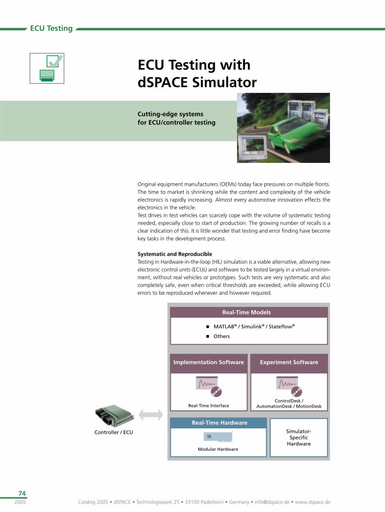
Systematic and Reproducible Testing in Hardware-in-the-loop (HIL) simulation is a viable alternative, allowing new electronic control units (ECUs) and software to be tested largely in a virtual environ-ment, without real vehicles or prototypes. Such tests are very systematic and also completely safe, even when critical thresholds are exceeded, while allowing ECU errors to be reproduced whenever and however required.
Catalog 2005 • dSPACE • Technologiepark 25 • 33100 Paderborn • Germany • [email protected] • www.dspace.de 2005
75
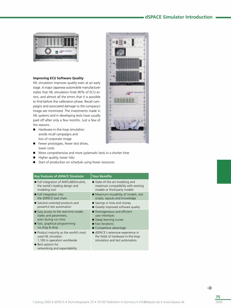
Improving ECU Software QualityHIL simulation improves quality even at an early stage. A major Japanese automobile manufacturer states that HIL simulation fi nds 90% of ECU er-rors, and almost all the errors that it is possible to fi nd before the calibration phase. Recall cam-paigns and associated damage to the company’s image are minimized. The investments made in HIL systems and in developing tests have usually paid off after only a few months. Just a few of the reasons:
Hardware-in-the-loop simulation avoids recall campaigns and loss of corporate image
Fewer prototypes, fewer test drives, lower costs
More comprehensive and more systematic tests in a shorter time Higher quality, lower risks Start of production on schedule using fewer resources
dSPACE Simulator Introduction
Key Features of dSPACE Simulator Your Benefi ts
Full integration of MATLAB/Simulink, the world‘s leading design and modeling tool
State-of-the-art modeling and maximum compatibility with existing models or third-party models
Full integration into the dSPACE tool chain
Maximum reusability of models, test scripts, layouts and knowledge
Solution-oriented products and powerful test automation
Savings in time and money Greatly improved software quality
Easy access to the real-time model, states and parameters, even during run time
Fast, graphical programming via drag & drop
Homogeneous and effi cient user interfaces
Steep learning curves Fast iterations Competitive advantage
Product maturity as the world’s most used HIL simulator: 1,100 in operation worldwide
Best options for networking and expandability
dSPACE‘s extensive experience in the fi elds of hardware-in-the-loop simulation and test automation
Catalog 2005 • dSPACE • Technologiepark 25 • 33100 Paderborn • Germany • [email protected] • www.dspace.de2005
76
ECU Testing
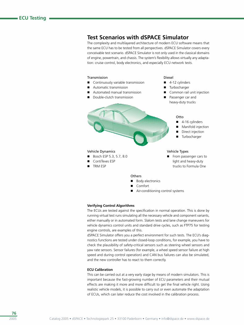
Test Scenarios with dSPACE Simulator The complexity and multilayered architecture of modern ECU software means that the same ECU has to be tested from all perspectives. dSPACE Simulator covers every conceivable test scenario. dSPACE Simulator is not only used in the classical domains of engine, powertrain, and chassis. The system’s fl exibility allows virtually any adapta-tion: cruise control, body electronics, and especially ECU network tests.
Verifying Control AlgorithmsThe ECUs are tested against the specifi cation in normal operation. This is done by running virtual test runs simulating all the necessary vehicle and component variants, either manually or in automated form. Slalom tests and lane change maneuvers for vehicle dynamics control units and standard drive cycles, such as FTP75 for testing engine controls, are examples of this.dSPACE Simulator offers you a perfect environment for such tests. The ECU’s diag-nostics functions are tested under closed-loop conditions, for example, you have to check the plausibility of safety-critical sensors such as steering wheel sensors and yaw rate sensors. Sensor failures (for example, a wheel speed sensor failure at high speed and during control operation) and CAN bus failures can also be simulated, and the new controller has to react to them correctly.
ECU CalibrationThis can be carried out at a very early stage by means of modern simulators. This is important because the fast-growing number of ECU parameters and their mutual effects are making it more and more diffi cult to get the fi nal vehicle right. Using realistic vehicle models, it is possible to carry out or even automate the adaptation of ECUs, which can later reduce the cost involved in the calibration process.
Vehicle Dynamics Bosch ESP 5.3, 5.7, 8.0 ContiTeves ESP TRM ESP
Otto 4-16 cylinders Manifold injection Direct injection Turbocharger
Diesel 4-12 cylinders Turbocharger Common rail unit injection Passenger car and
heavy-duty trucks
Transmission Continuously variable transmission Automatic transmission Automated manual transmission Double-clutch transmission
Others Body electronics Comfort Air-conditioning control systems
Vehicle Types From passenger cars to
light and heavy-duty trucks to Formula One
Catalog 2005 • dSPACE • Technologiepark 25 • 33100 Paderborn • Germany • [email protected] • www.dspace.de 2005
77
Integration Tests on ECU NetworksThe main concern is to test problem-free interaction of all the ECUs that are com-municating, e.g., via CAN and LIN. Network tests have become necessary mainly because of the growing number of ECUs from different manufacturers that perform their overall function only when networked.
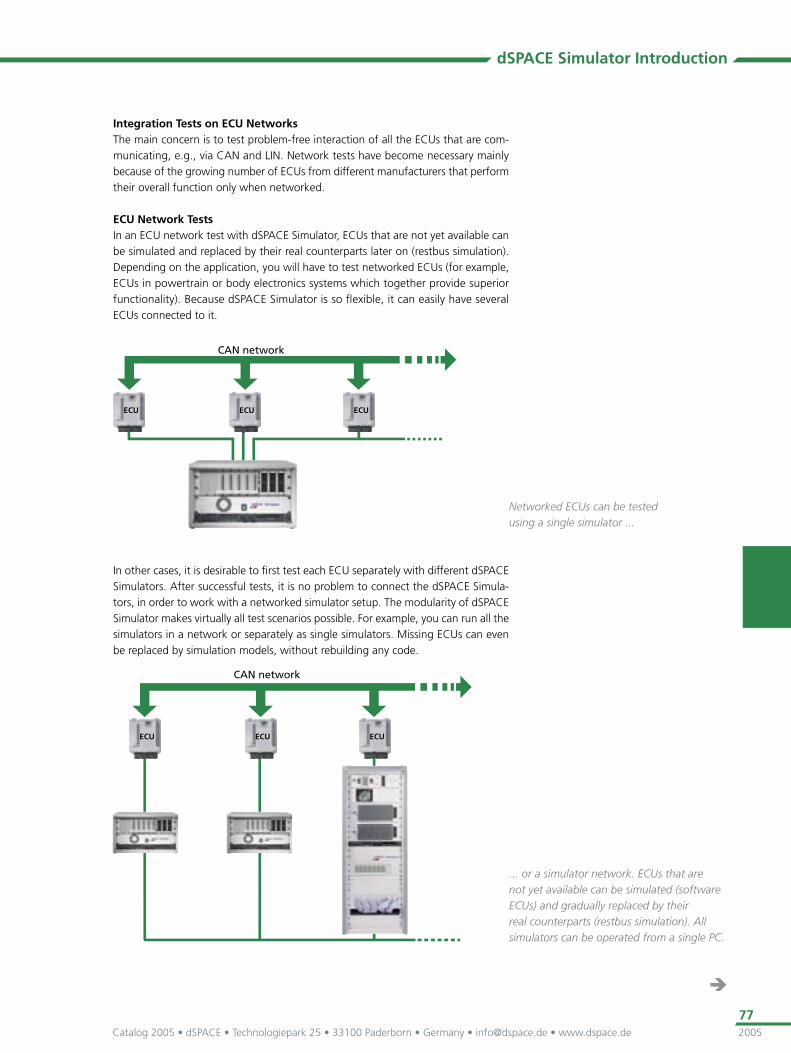
ECU Network TestsIn an ECU network test with dSPACE Simulator, ECUs that are not yet available can be simulated and replaced by their real counterparts later on (restbus simulation). Depending on the application, you will have to test networked ECUs (for example, ECUs in powertrain or body electronics systems which together provide superior functionality). Because dSPACE Simulator is so fl exible, it can easily have several ECUs connected to it.
... or a simulator network. ECUs that are not yet available can be simulated (software ECUs) and gradually replaced by their real counterparts (restbus simulation). All simulators can be operated from a single PC.
dSPACE Simulator Introduction
Networked ECUs can be tested using a single simulator ...
In other cases, it is desirable to fi rst test each ECU separately with different dSPACE Simulators. After successful tests, it is no problem to connect the dSPACE Simula-tors, in order to work with a networked simulator setup. The modularity of dSPACE Simulator makes virtually all test scenarios possible. For example, you can run all the simulators in a network or separately as single simulators. Missing ECUs can even be replaced by simulation models, without rebuilding any code.
Catalog 2005 • dSPACE • Technologiepark 25 • 33100 Paderborn • Germany • [email protected] • www.dspace.de2005
78
ECU Testing
Testing Diagnostic FunctionsTo test diagnostic functions (e.g., OBDII and EOBD), the ECU behavior when faults occur is tested. The vehicle is simulated in a closed-loop environment and systemati-cally drives through all the defi ned operating points. This allows the diagnostics to be tested systematically. Typical diagnostic tests relate to the plausibility of signals or defective electrical connections. It is important for diagnostic tests to be run com-pletely automatically, as release tests often have to be performed within an extremely short time. dSPACE Simulator fl exibly creates different scenarios for different ECUs, allowing a great diversity of versions to be handled. In the near future, Automa-tionDesk (p. 140) offers a powerful and convenient test automation environment to make systematic testing even more effi cient.
The Benefi ts of dSPACE Simulator
dSPACE – A Competent HIL PartnerdSPACE is your partner in selecting the right system and installing and confi guring your dSPACE Simulator.
Delivery on schedule (approx. 3 months for a single Simulator Full-Size, approx. 6 months for simulator networks for over 30 ECUs)
Professional project management and fast commissioning
Our offi ces can help you get the most out of your dSPACE Simulator by offering additional services such as training sessions and on-site support.
Technical LeaddSPACE Simulator is the world’s leading system for the systematic testing of electronics and software. There are currently more than 1,100 simulators with dSPACE technology in use worldwide, nearly all of them at major automotive companies such as Audi, BMW, DaimlerChrysler, DENSO, Ford, Magneti Marelli, Nissan, Opel, Renault, Toyota, Volkswagen and several Formula One teams.
Broad range of experience: diesel, spark ignition and direct injection engines, transmission, vehicle dynamics, and vehicle interior systems
Support of networked ECUs (example: 36 ECUs, more than 7,000 signals on 4 CAN busses and 10 LIN busses, plus 2,000 further I/O signals) and even the complete vehicle electronics system
Battery network management (sleep, wake-up) tested by precise measurement of sleep-mode current and operation current from 1 µA to over 100 A
Exemplary hardware and software tools for error-fi nding and test automation
Applications: cars, light and heavy-duty trucks, racing (Formula One, rally), aerospace
dSPACE Simulator offers everything you need to perform your tests: Tight integration of dSPACE software and the modeling tool MATLAB/Simulink from The MathWorks provides a powerful development environment. And the powerful and robust dSPACE hardware always sets the standards for HIL technology.

Catalog 2005 • dSPACE • Technologiepark 25 • 33100 Paderborn • Germany • [email protected] • www.dspace.de 2005
79
dSPACE Simulator Introduction
Test Effi ciencydSPACE Simulator’s graphical user interfaces provide a convenient and fl exible environment. Simulated driving cycles, data acquisition, instrumentation, monitoring, test automation and all other tasks are executed graphically within dSPACE Simulator.dSPACE software gives you the greatest possible test effi ciency and ease of use.
Signal Generation and MeasurementThese are just a few of the automotive signals that can be generated and measured by dSPACE Simulator
Algorithm- and waveform-based signal generation (e.g., crankshaft, camshaft, knocking signals)
Generation of PWM sensor signals and Hall sensor signals (e.g., wheel speed, fuel level)
Generation of resistance-based sensor signals (e.g., temperature) Generation and measurement of analog and digital sensor signals
(e.g., throttle, switches, lamps, relays) Simulation of linear lambda probes Angle-based measurement of injection and ignition pulses Measurement of PWM actuator signals (e.g., solenoid valves) Connection to CAN, LIN, FlexRay and serial interfaces
Example: Compensation of potential gradients caused by... Cable resistance The ECU’s varying power consumption in different operating conditions
...and our solutions in dSPACE Simulator: Differential analog inputs and outputs Potential-free resistance outputs Output transformers for all fast analog outputs
dSPACE Simulator ComponentsFor details on dSPACE Simulator’s modular concept, please see the following pages.

Catalog 2005 • dSPACE • Technologiepark 25 • 33100 Paderborn • Germany • [email protected] • www.dspace.de2005
80
ECU Testing
Implementation SoftwareThe code for dSPACE Simulator‘s real-time hardware is generated automatically, directly from MATLAB/Simulink. Your MATLAB/Simulink model is connected to the real-time hardware via drag & drop. Powerful software tools are available for this:
Real-Time Interface for implementing Simulink and Statefl ow models on dSPACE Simulator
Optional extensions to Real-Time Interface
Real-Time Interface (RTI)dSPACE‘s Real-Time Interface completely integrates MATLAB/Simulink and offers additional blocks to connect models and our I/O hardware. For example, there are comprehensive libraries for the DS2211 HIL I/O Board, our most powerful I/O board for HIL applications. RTI’s graphical user interface reduces the work involved in supplementary model changes and I/O adjustments to a minimum.
Real-Time Interface (p. 108)
Graphical programming and connection to I/O, CAN bus or LIN bus: everything is done graphically in Simulink with our Real-Time Interface.
Confi guring CAN and LIN Bus CommunicationConfi guring your CAN bus communication graphically from Simulink is no problem with the additional RTI CAN Blockset. With our new RTI CAN MultiMessage Blockset, you can confi gure and control a large number of CAN messages (more than 200) from one single Simulink block.To simulate communication in a LIN network, we also provide the RTI LIN Blockset for effortless confi guration of LIN master and slave nodes simulated on the DS4330 LIN Interface Board.
Real-Time Interface CAN Blockset (p. 116) Real-Time Interface CAN MultiMessage Blockset (p. 118) Real-Time Interface LIN Blockset (p. 120)
Catalog 2005 • dSPACE • Technologiepark 25 • 33100 Paderborn • Germany • [email protected] • www.dspace.de 2005
81
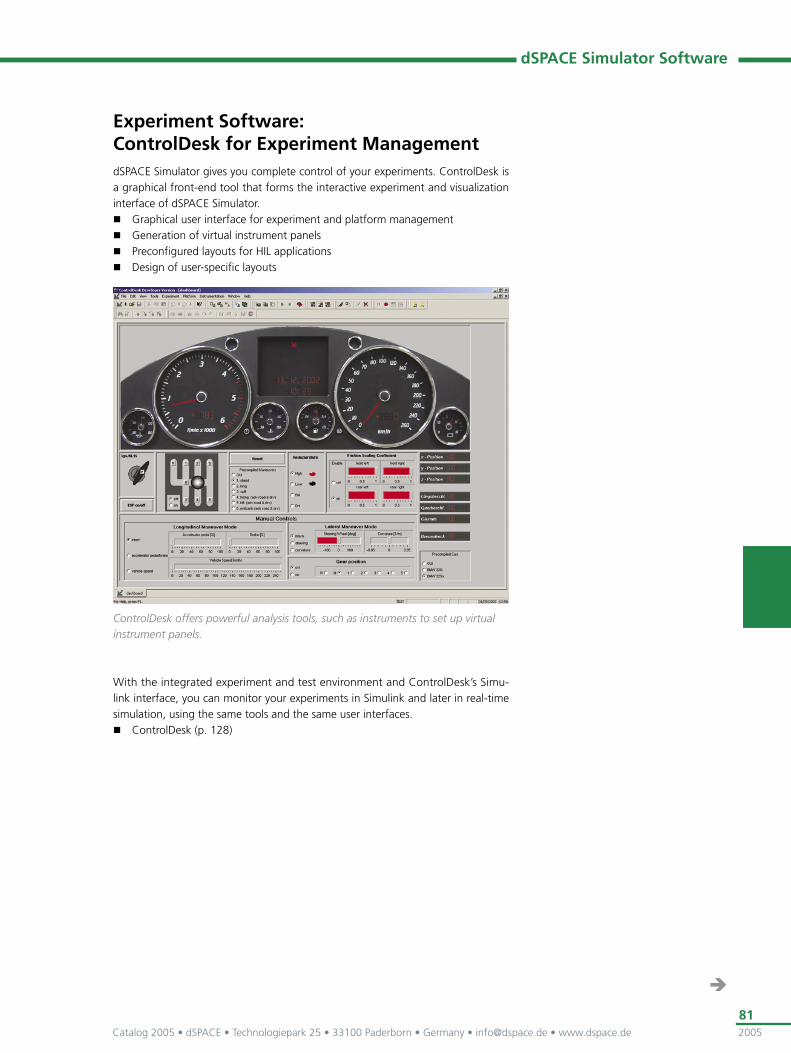
Experiment Software: ControlDesk for Experiment ManagementdSPACE Simulator gives you complete control of your experiments. ControlDesk is a graphical front-end tool that forms the interactive experiment and visualization interface of dSPACE Simulator.
Graphical user interface for experiment and platform management Generation of virtual instrument panels Preconfi gured layouts for HIL applications Design of user-specifi c layouts
ControlDesk offers powerful analysis tools, such as instruments to set up virtual instrument panels.
With the integrated experiment and test environment and ControlDesk’s Simu-link interface, you can monitor your experiments in Simulink and later in real-time simulation, using the same tools and the same user interfaces.
ControlDesk (p. 128)
dSPACE Simulator Software
Catalog 2005 • dSPACE • Technologiepark 25 • 33100 Paderborn • Germany • [email protected] • www.dspace.de2005
82
ECU Testing
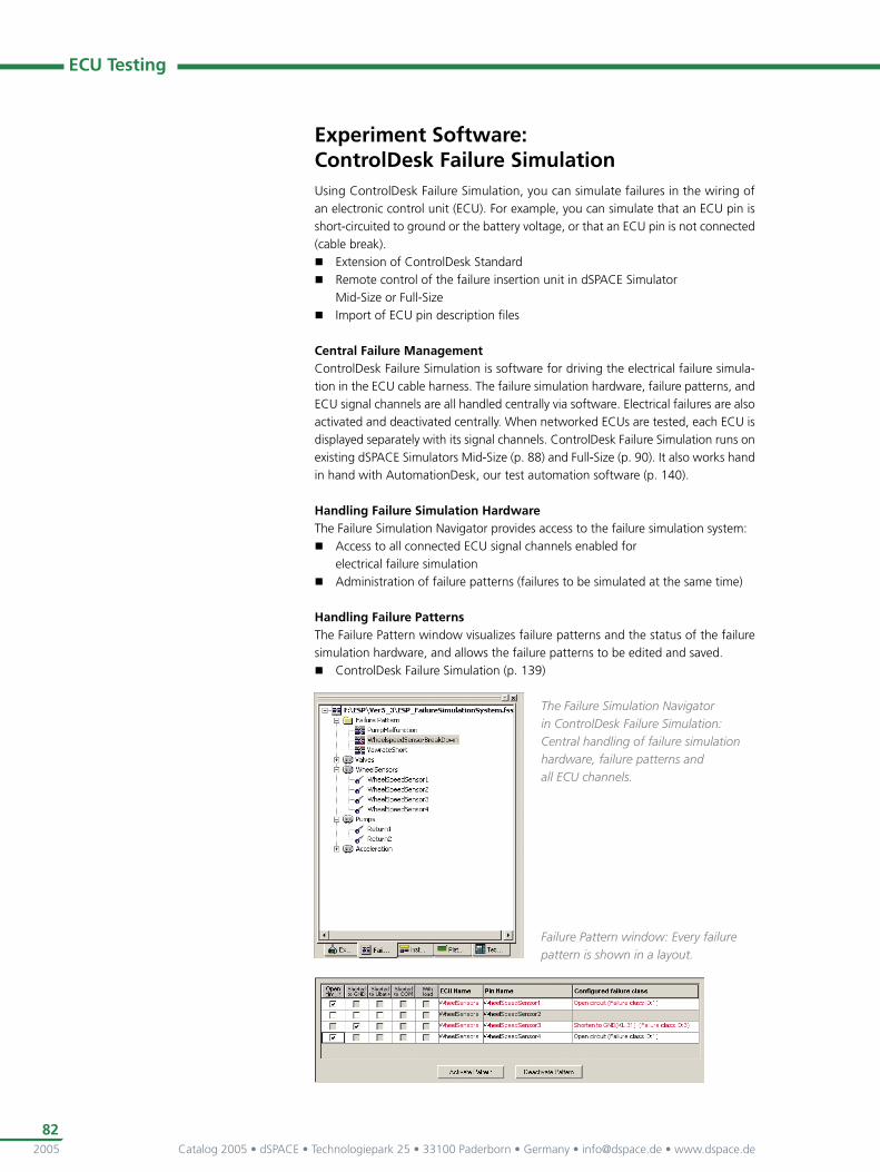
Experiment Software: ControlDesk Failure SimulationUsing ControlDesk Failure Simulation, you can simulate failures in the wiring of an electronic control unit (ECU). For example, you can simulate that an ECU pin is short-circuited to ground or the battery voltage, or that an ECU pin is not connected (cable break).
Extension of ControlDesk Standard Remote control of the failure insertion unit in dSPACE Simulator
Mid-Size or Full-Size Import of ECU pin description fi les
Central Failure ManagementControlDesk Failure Simulation is software for driving the electrical failure simula-tion in the ECU cable harness. The failure simulation hardware, failure patterns, and ECU signal channels are all handled centrally via software. Electrical failures are also activated and deactivated centrally. When networked ECUs are tested, each ECU is displayed separately with its signal channels. ControlDesk Failure Simulation runs on existing dSPACE Simulators Mid-Size (p. 88) and Full-Size (p. 90). It also works hand in hand with AutomationDesk, our test automation software (p. 140).
Handling Failure Simulation HardwareThe Failure Simulation Navigator provides access to the failure simulation system:
Access to all connected ECU signal channels enabled for electrical failure simulation
Administration of failure patterns (failures to be simulated at the same time)
Handling Failure PatternsThe Failure Pattern window visualizes failure patterns and the status of the failure simulation hardware, and allows the failure patterns to be edited and saved.
ControlDesk Failure Simulation (p. 139)
The Failure Simulation Navigator in ControlDesk Failure Simulation: Central handling of failure simulation hardware, failure patterns and all ECU channels.
Failure Pattern window: Every failure pattern is shown in a layout.

Catalog 2005 • dSPACE • Technologiepark 25 • 33100 Paderborn • Germany • [email protected] • www.dspace.de 2005
83
Test Software: AutomationDesk AutomationDesk facilitates the task of developing and managing tests.
Automated testing in HIL simulation Graphical user interface for managing test projects Graphical editor for describing automation sequences
AutomationDesk is ideal for automating hardware-in-the-loop tests. AutomationDesk offers a convenient test automation environment, which supports the development and handling of large test projects and test sequences. With AutomationDesk, the sys-tematic structure, reusability, and reproducibility of test sequences are unequalled.
AutomationDesk (p. 140)
Typical Automation Tasks – Executed with AutomationDesk
Setting up operating point ECU initialization (e.g., failure memory reset) and simulator environment
Stimulus signal generation (to switch short circuit failures or to input reference trajectories)
Access to real-time variables during run time
Measurement Access to ECU internal variables via diagnostic or calibration interfaces
Data capturing of simulator variables
Evaluation and test reporting Access to MATLAB’s mathematical test validation capabilities or direct calculations in Python
Automated report generation based on XML with standard style sheets for HTML and PDF
Data management Organization and storage of test sequences, parameter sets, measurement data and test reports
dSPACE Simulator Software
Catalog 2005 • dSPACE • Technologiepark 25 • 33100 Paderborn • Germany • [email protected] • www.dspace.de2005
84
ECU Testing
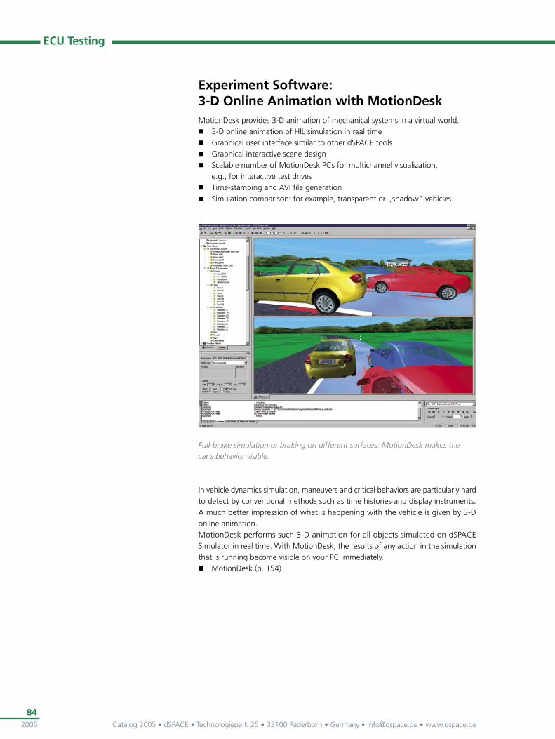
Experiment Software: 3-D Online Animation with MotionDeskMotionDesk provides 3-D animation of mechanical systems in a virtual world.
3-D online animation of HIL simulation in real time Graphical user interface similar to other dSPACE tools Graphical interactive scene design Scalable number of MotionDesk PCs for multichannel visualization,
e.g., for interactive test drives Time-stamping and AVI fi le generation Simulation comparison: for example, transparent or „shadow” vehicles
In vehicle dynamics simulation, maneuvers and critical behaviors are particularly hard to detect by conventional methods such as time histories and display instruments. A much better impression of what is happening with the vehicle is given by 3-D online animation.MotionDesk performs such 3-D animation for all objects simulated on dSPACE Simulator in real time. With MotionDesk, the results of any action in the simulation that is running become visible on your PC immediately.
MotionDesk (p. 154)
Full-brake simulation or braking on different surfaces: MotionDesk makes the car’s behavior visible.
Catalog 2005 • dSPACE • Technologiepark 25 • 33100 Paderborn • Germany • [email protected] • www.dspace.de 2005
85
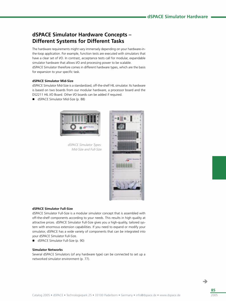
dSPACE Simulator Hardware Concepts – Different Systems for Different TasksThe hardware requirements might vary immensely depending on your hardware-in-the-loop application. For example, function tests are executed with simulators that have a clear set of I/O. In contrast, acceptance tests call for modular, expandable simulator hardware that allows I/O and processing power to be scalable. dSPACE Simulator therefore comes in different hardware types, which are the basis for expansion to your specifi c task.
dSPACE Simulator Mid-SizedSPACE Simulator Mid-Size is a standardized, off-the-shelf HIL simulator. Its hardware is based on two boards from our modular hardware, a processor board and the DS2211 HIL I/O Board. Other I/O boards can be added if required.
dSPACE Simulator Mid-Size (p. 88)
dSPACE Simulator Full-SizedSPACE Simulator Full-Size is a modular simulator concept that is assembled with off-the-shelf components according to your needs. This results in high quality at attractive prices. dSPACE Simulator Full-Size gives you a high-quality, tailored sys-tem with enormous extension capabilities. If you need to expand or modify your simulator, dSPACE has a wide variety of components that can be integrated into your dSPACE Simulator Full-Size.
dSPACE Simulator Full-Size (p. 90)
Simulator NetworksSeveral dSPACE Simulators (of any hardware type) can be connected to set up a networked simulator environment (p. 77).
dSPACE Simulator Hardware
dSPACE Simulator Types: Mid-Size and Full-Size

Catalog 2005 • dSPACE • Technologiepark 25 • 33100 Paderborn • Germany • [email protected] • www.dspace.de2005
86
ECU Testing
Hardware Summary
dSPACE Simulator Mid-Size (p. 88)
dSPACE Simulator Full-Size (p. 90)
Form factor 19“ desktop rack 19“ cabinet 17 – 37 HU Vertical modules
Processor hardware DS1005 PPC Board or DS1006 Processor Board
DS1005 PPC Board or DS1006 Processor Board
I/O hardware DS2211 HIL I/O Board Any number and type of dSPACE I/O boards
Further I/O hardware
Signal conditioning
Substitute loads
Real-load connector
Failure insertion unit
Integration of simulator-specifi c hardware (p. 74)
Integration of third-party hardware, e.g., load panels
ECU connectors Three 90-pin connectors Additional connectors for additional I/O optional
One or more 90-pin connectors for each ECU (standardized)
Additional connectors optional
Break-out box
OBDII diagnostic connector / connection to diagnostic tools
Sub-D connector with optional CARB adapter
CAN connector
Standard 16-pin CARB connector
Diagnostic connectors (CAN, K-line)
Others on request
Truck applications-capable (24 V/36 V)
42 V-capable
Power supply (remote controlled)
Included Available on demand

Catalog 2005 • dSPACE • Technologiepark 25 • 33100 Paderborn • Germany • [email protected] • www.dspace.de 2005
87
Failure Simulation Summary Failure simulation can be performed with both dSPACE Simulator Mid-Size and dSPACE Simulator Full-Size. Powerful failure simulation hardware further boosts their functionality.
dSPACE Simulator Mid-Size
Standard Hardware Extension
Failure insertion units 5 x DS749 FIU Module (each features 10 channels)
Optional: replaced with 5 x DS792 Fuse Cards
n x DS793/DS794 Sensor FIU Cards (up to 2 cards, each 81 channels with CMOS switches)
Possible failure types On ECU outputs: Cable break Short circuit to ground Short circuit to battery voltage
Short circuit to another ECU pin via two fail planes
On ECU inputs: Cable break (open line) Short circuit to ground Short circuit to battery voltage
Short circuit to another ECU pin via two fail planes
dSPACE Simulator Full-Size
Failure Simulation Variant 1 Failure Simulation Variant 2
Failure insertion units n x DS291 FIU Module (each features 10 channels)
n x DS281 Load Module
1 x DS293 Central FIU Module
n x DS282 Load Module (10 channels)
1 x DS289 Rsim Module (simulates a resistance in the range 1 Ω ...131 kΩ in steps of 1 Ω )
Possible failure types On ECU inputs and outputs:· Open circuit Short circuit to ground or minus pole of the battery (KL31) with connected/disconnected load (an ECU input is disconnected from a dSPACE output channel)
Short circuit to plus pole of the battery (KL30) with connected/disconnected load (an ECU input is disconnected from a dSPACE output channel)
Short circuit to another ECU pin with or without load (via common rail)
On ECU inputs and outputs: Open circuit with or without additional hardware (Rsim, MEAS or SOURCE) in series
Short circuit to another ECU pin directly or via additional hardware
Short circuit to 5 reference points (potential 0…4) directly or via additional hardware
dSPACE Simulator Hardware

Catalog 2005 • dSPACE • Technologiepark 25 • 33100 Paderborn • Germany • [email protected] • www.dspace.de2005
88
ECU Testing
dSPACE Simulator Mid-Size: Hardware DetailsThe hardware of dSPACE Simulator Mid-Size is mounted in a 19” desktop rack (height: 6 – 9 HU). The simulation model runs on the processor board. dSPACE Simulator Mid-Size generates and measures I/O signals via the DS2211 HIL I/O Board, which also performs the signal conditioning. Additional I/O and signal conditioning can be added on request.
Hardware summary (p. 86)
Failure insertion units, load cards, external connection of real loads
Spare slot
Modular hardware: processor board and I/O board with signal conditioning
OBDII connector via adapter
ECU connectors
Remote-controlled power supply (battery simulation)
Connection to Host PCAll dSPACE software (p. 106) for experiment setup and control runs on your PC or notebook. The dSPACE Simulator hardware is connected to your PC via link boards (ISA, PCMCIA, or PCI, p. 322).
Typical Fields of Application Engine, transmission and vehicle dynamics HIL Realistic software system tests/unit tests Function integration tests Open-loop or closed-loop environment Automated testing of diagnostic functions that check the ECU outputs
Hardware Components Installation in 19” desktop rack (see table) Integrated signal conditioning for all DS2211 signals
Enclosure Variants
dSPACE Simulator Mid-Size Standard variant, 2-voltage system optional
Small variant, 1-voltage system
DS1005 PPC Board or DS1006 Processor Board
DS2211 HIL I/O Board
Failure insertion units
Load cards
Power supply
Second power supply −
Free ISA slots for expansion 1 (PX5 version, only for DS1005 PPC Board)
5 (PX10 version)
1 (PX5 version, only for DS1005 PPC Board)
Height units 9 6
Included Optional
Catalog 2005 • dSPACE • Technologiepark 25 • 33100 Paderborn • Germany • [email protected] • www.dspace.de 2005
89
dSPACE Simulator Mid-Size
Signal Conditioning On-board for DS2211 HIL I/O Board signals Two spare slots for additional signal conditioning (e.g., current measurement
for diesel and stratifi ed injection applications, lambda probe simulation or signal conditioning for additional I/O boards)
Failure Insertion UnitsA standard dSPACE Simulator Mid-Size supports electrical failure simulation on all ECU output pins connected to the DS2211. A hardware extension allows electrical failures to be simulated on ECU inputs as well. The host PC controls both types of failure simulation via an RS232 interface. See p. 67 for further information.
ECU outputs: Five failure insertion units (FIUs) with 10 channels, connected to all 50 actuator channels; Optional: replaced with 5 x DS792 Fuse Cards
ECU inputs: optional, via hardware extension (p. 67) Remote-controlled with ControlDesk Failure Simulation and (on request)
automated with AutomationDesk Simulation of shorts: shorts from ECU pins to ground or battery voltage Cable break simulation (open wire) Simulation of cross-wired short circuits via two fail planes Simultaneous activation of multiple failures (latch mode)
Load Capabilities Five load cards, 10 single-ended loads or 5 double-ended loads each 2 W maximum continuous power per load (substitute loads) 8 A maximum load current per pin (real loads) LED indicators displaying current load states (display mode selectable) Front connector for measurement or connection of real loads
VBat Jacks Provides power voltage of both power supplies for external devices
(e.g., external test or diagnostic devices) 4 mm sockets
Power Supply Programmable switched-mode power supplies (remote-controlled, 2 power
supplies required for simulation of vehicle batteries in 2-voltage systems) Support of 24-V systems with the fi rst system Support of 42-V systems with the second system Three switched battery rails for each battery voltage,
e.g., main relay, ECU-controlled high rail 16 A maximum current for each rail of fi rst battery voltage 7.5 A maximum current for each rail of second battery voltage
Other Hardware Components Break-out box (optional)
Expandability Expansion with further DS2211 HIL I/O Boards (cascadable),
ECU Interface or CAN Interface boards Inclusion of real loads, additional, or customer-specifi c signal conditioning
(e.g., current measurement for diesel or stratifi ed injection applications) or signal conditioning for an additional I/O board
Customer-specifi c modifi cations/extensions possible

Catalog 2005 • dSPACE • Technologiepark 25 • 33100 Paderborn • Germany • [email protected] • www.dspace.de2005
90
ECU Testing
dSPACE Simulator Full-Size: Hardware DetailsdSPACE Simulator Full-Size is mounted in a 19” cabinet whose height depends on your requirements. The dSPACE boards are mounted in a standard PX20 Expansion Box (p. 321). The PX20 Expansion Box provides 20 ISA slots for dSPACE boards, and an additional Expansion Box can be integrated, so you never face restrictions on expandability.
Open Hardware ConceptThe simulation model runs on the processor hardware (single-processor or multi-processor systems, based on processor boards).dSPACE Simulator generates and measures I/O signals via the integrated dSPACE I/O boards. The signal conditioning, loads, failure insertion units and power supply are also mounted in the 19” cabinet. The number of components, and their types, depend on your requirements and are confi gured to fi t your application.
Additional connectors (e.g., CARB, OBD)
Power supply
Break-out box ECU connector
Connector for external loads
Loads and failure simulation (remote-controlled)
Signal conditioning
Modular hardware: processor boards and I/O boards
Connection to Host PCAll dSPACE software for setting up and controlling experiments runs on your PC or notebook. The dSPACE Simulator hardware is connected to your PC via Link Boards (ISA, PCMCIA, or PCI, p. 322).
Catalog 2005 • dSPACE • Technologiepark 25 • 33100 Paderborn • Germany • [email protected] • www.dspace.de 2005
91
dSPACE Simulator Full-Size
Typical Fields of Application Engine, powertrain, and vehicle dynamics HIL Comprehensive closed-loop tests on ECUs, release/acceptance tests Networked ECUs Special requirements, e.g., with high system fl exibility Truck applications Racing applications (Formula One, rally)
Hardware Components Installation in 19” cabinet Single-processor or multiprocessor systems, based on processor boards PX20 Expansion Box for modular dSPACE hardware Freely expandable by any dSPACE I/O board (see Modular Hardware, p. 224),
according to your requirements Expandable, e.g., with hardware for signal conditioning,
failure insertion and load simulation
Signal Conditioning Signal conditioning for all dSPACE I/O boards Modular signal conditioning concept (off-the-shelf components,
customer-specifi c confi guration) Supports almost any signal type: e.g., digital in, digital out, analog in,
analog out, relay simulation, current sink/source, LVDT simulation, resistance simulation
Further modules on demand
Failure Insertion Units Failure insertion unit (FIU) for ECU inputs and outputs Modular FIU concept (customer-specifi c confi guration) Remote-controlled with ControlDesk Failure Simulation
(and optionally with AutomationDesk) Simulation of shorts: shorts from ECU pins to ground,
battery voltage, or switched rail Cable break simulation (open wire) Simulation of cross-wired short circuits Simultaneous activation of multiple failures (latch mode)
Failure Simulation Variant 1Our standard variant for failure simulation on dSPACE Simulator Full-Size supports failure simulation on all ECU input and output pins. All digital and analog I/O boards from dSPACE are supported by failure simulation. The relay boards (DS291) for failure simulation can be used on their own or in conjunction with load boards (DS281). Failure relays are controlled via a serial RS232.
Failure Simulation Variant 1 (p. 87)
Failure Simulation Variant 2Our second failure simulation variant uses a central relay switching matrix (DS293) for failure simulation on ECU inputs and outputs. Signal channels can be switched in on three different rails via load modules (DS282). Further devices that can be connected include 5 different system potentials (for example, KL30, KL31, KL15), various measurement devices, and Rsim modules (DS289 for simulating real substitute loads). See p. 87 for further information. Failure simulation is controlled via a CAN interface.
Failure Simulation Variant 2 (p. 87)

Catalog 2005 • dSPACE • Technologiepark 25 • 33100 Paderborn • Germany • [email protected] • www.dspace.de2005
92
ECU Testing
Load Capabilities Modular load concept (customer-specifi c confi guration) Support of single-ended and double-ended loads Resistive loads or other kinds of equivalent loads Connection of electrically equivalent loads or low-power resistive loads Connection of real loads, can be integrated in the cabinet Integration of customers‘ load panels
Power Supply Simulation of car battery Programmable switched-mode power supply Remote-controlled 42 V and truck-capable: 0 … 50 V voltage range
Other Hardware Components Break-out box (optional, integrated in cabinet or external) Optional inclusion of third-party hardware;
e.g., load panels, signal routing units, GPIB instruments Power switch modules (p. 94)
Expandability Maximum fl exibility through modular concept Minimum hardware modifi cation when requirements change Supersets with spare signals, allowing tests on several ECU variants,
even after ECU pinout changes All signals accessible on terminal strips for additional measurement tasks Clear and transparent system architecture Multirack systems possible

Catalog 2005 • dSPACE • Technologiepark 25 • 33100 Paderborn • Germany • [email protected] • www.dspace.de 2005
93
Simulator-Specifi c Hardware
Simulator-Specifi c HardwareIf you need to expand or modify your simulator, dSPACE has a wide variety of off-the shelf components that can be integrated into your dSPACE Simulator. dSPACE Simulator Full-Size can be equipped with simulator-specifi c hardware for optimum tailoring to your specifi c needs. dSPACE Simulator Mid-Size can also be similarly equipped to a certain extent. The simulator-specifi c hardware includes real system components and signal con-ditioning, as well as measurement and diagnostic tools. The components and tools can be built and integrated by dSPACE, third-party suppliers, or you yourself.The setup shown in the illustration is typical of many application areas, and you can also add or remove as many components as you like.
Catalog 2005 • dSPACE • Technologiepark 25 • 33100 Paderborn • Germany • [email protected] • www.dspace.de2005
94
ECU Testing
Examples of Simulator-Specifi c Hardware
Interface to Diagnostic and Calibration HardwareMany companies already have their own diagnostic and calibration hardware to perform tasks such as reading out internal ECU variables from the failure memory. If you do not intend to run this functionality on dSPACE Simulator, the hardware is connected to dSPACE Simulator via appropriate interfaces, which might in some cases need a little engineering. You can connect any kind of measuring device, digital scope, and diagnostic device you like with special protocols such as GPIB or RS232.
Real System ComponentsIn some cases, the real system components (such as injection valves, hydraulic com-ponents, and sensors) have to be integrated into dSPACE Simulator. This is necessary, for example, if ECUs and related components come from different suppliers and have to be checked within the simulated environment. Moreover, not every vehicle component can be simulated with a justifi able amount of time and money, and many ECUs require real loads at their outputs in order to function at all.
Break-Out BoxesAn optional break-out box makes all ECU pins directly accessible. This simplifi es the measurement and input of signals. The break-out boxes can be integrated into dSPACE Simulator, or take the form of external desktop boxes. Third-party break-out adapters can also be included (available for dSPACE Simulator Mid-Size and Full-Size).
Relay and Failure Insertion UnitsAny number and type of open circuits and short circuits can be simulated by using relay and failure boxes. Besides our failure insertion unit, it is also possible to integrate customer-specifi c and third-party solutions.
Programmable Power SupplyThe programmable power unit supplies the components to be tested and enables the simulation of real voltages such as the battery voltage of a vehicle during start-up. The power supply unit is remote-controlled from within the real-time model.
Power Switch ModuleECUs consume power even when the vehicle is parked. Many modern ECUs have a sleep mode to avoid draining the vehicle’s electrical system unnecessarily. Some ECUs therefore contain a CAN transceiver capable of sleep mode, which allows the ECU to run only if it is needed and switches it off otherwise. Power switch modules provide network management for such systems to be tested, e.g., with sleep mode and wake-up functions.Moreover, systems with networked ECUs often require different power supply voltage levels. Each power switch module therefore handles two power supplies to simulate different vehicle electrical systems within dSPACE Simulator. Even the sequence when a vehicle is starting up can be simulated.A measurement unit allows the precise current measurement of each ECU in different current ranges, even in the microampere range. For example, current consumption during ECU sleep mode can be compared with normal operation mode behavior. The module is controlled by software via a CAN interface.
Catalog 2005 • dSPACE • Technologiepark 25 • 33100 Paderborn • Germany • [email protected] • www.dspace.de 2005
95
Signal ConditioningReal components usually cannot be connected directly to the real-time hardware. The signal level of the ECU and other connected components must fi rst be adapted to the I/O interfaces of the real-time hardware. The signal conditioning necessary for adaptation is an important part of dSPACE Simulator and includes protection circuits, signal preparation, etc., in addition to level adaptations.
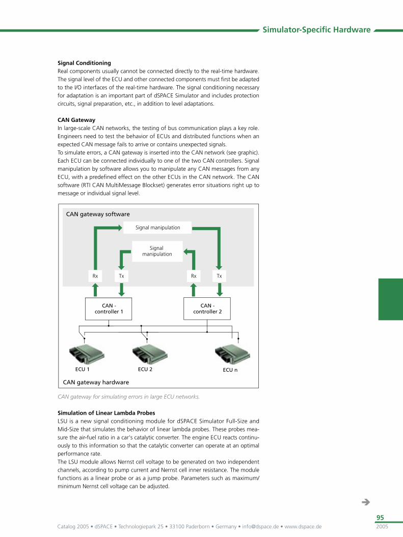
CAN GatewayIn large-scale CAN networks, the testing of bus communication plays a key role. Engineers need to test the behavior of ECUs and distributed functions when an expected CAN message fails to arrive or contains unexpected signals. To simulate errors, a CAN gateway is inserted into the CAN network (see graphic). Each ECU can be connected individually to one of the two CAN controllers. Signal manipulation by software allows you to manipulate any CAN messages from any ECU, with a predefi ned effect on the other ECUs in the CAN network. The CAN software (RTI CAN MultiMessage Blockset) generates error situations right up to message or individual signal level.
CAN gateway for simulating errors in large ECU networks.
Simulation of Linear Lambda ProbesLSU is a new signal conditioning module for dSPACE Simulator Full-Size and Mid-Size that simulates the behavior of linear lambda probes. These probes mea-sure the air-fuel ratio in a car‘s catalytic converter. The engine ECU reacts continu-ously to this information so that the catalytic converter can operate at an optimal performance rate.The LSU module allows Nernst cell voltage to be generated on two independent channels, according to pump current and Nernst cell inner resistance. The module functions as a linear probe or as a jump probe. Parameters such as maximum/minimum Nernst cell voltage can be adjusted.
Simulator-Specifi c Hardware

Catalog 2005 • dSPACE • Technologiepark 25 • 33100 Paderborn • Germany • [email protected] • www.dspace.de2005
96
ECU Testing
Real-Time Models for dSPACE Simulator
Models from MATLAB/Simulink/Statefl owFor hardware-in-the-loop simulation, you need real-time models to simulate the real environment. dSPACE Simulator is optimally equipped for integrating simulation models from MATLAB/Simulink/Statefl ow. Thanks to years of cooperation between The MathWorks and dSPACE, the tools from these two companies are perfectly tailored to each other. This way, you can can use your own real-time models – or third-party models. For example, our partner TESIS DYNAware, Munich, Germany, offers Simulink-based simulation models for HIL simulators that really make your dSPACE Simulator come alive.
Model-Based DevelopmentAfter you develop your simulation model, you can test it with Simulink and ControlDesk‘s Simulink interface and then in real time on dSPACE Simulator – with the same layouts, test scripts and parameter sets.
Services for Real-Time ModelsBased on years of know-how in hardware-in-the-loop simulation, dSPACE also offers modeling services such as
Integration of models into dSPACE Simulator Parameterization of models based on customer data Model interfaces Integration of different modeling tools (Dymola, AmeSim, C-Code, others) Adaptation of customer models

Catalog 2005 • dSPACE • Technologiepark 25 • 33100 Paderborn • Germany • [email protected] • www.dspace.de 2005
97
Confi guration Examples
Confi guration Example: dSPACE Simulator for Testing Single ECUs dSPACE Simulator Mid-Size is the perfect choice for testing single ECUs or for test projects with fi xed ECU wiring.
Possible ECU Testing Tasks for This Confi guration Functional tests for single ECUs Integration tests for single ECUs Acceptance tests for single ECUs Release tests for single ECUs Virtual vehicles (when networked with other dSPACE Simulators)
Possible Test Areas for This Confi guration Gasoline engine Diesel engine Transmission Vehicle dynamics Climate control Comfort functions 12 … 42 V applications
Components (Example)
Third-Party Components Further Details
PC −
Modeling software MATLAB / Simulink / Statefl ow from The MathWorks
p. 35
Real-time model Real-time models for dSPACE Simulator
p. 96
Real-time code generation Real-Time Workshop p. 36
Software Components Further Details
Implementation software Real-Time Interface p. 108
PowerPC compiler p. 127
Experiment software ControlDesk p. 128
ControlDesk Failure Simulation
p. 139
AutomationDesk p. 140
Catalog 2005 • dSPACE • Technologiepark 25 • 33100 Paderborn • Germany • [email protected] • www.dspace.de2005
98
ECU Testing
Hardware Components Further Details
Modular hardware Processor Board: DS1005 PPC Board
p. 230
I/O boards: DS2211 HIL I/O Board
p. 254
Off-the-shelf hardware Failure insertion units p. 87
Load boards p. 87
One or two power supplies (two for 2-voltage system simulation)
p. 94
Others −
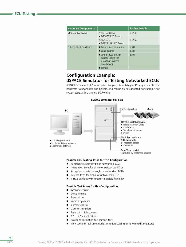
Confi guration Example: dSPACE Simulator for Testing Networked ECUs dSPACE Simulator Full-Size is perfect for projects with higher I/O requirements. The hardware is expandable and fl exible, and can be quickly adapted, for example, for system tests with changing ECU wiring.
Possible ECU Testing Tasks for This Confi guration Function tests for single or networked ECUs Integration tests for single or networked ECUs Acceptance tests for single or networked ECUs Release tests for single or networked ECUs Virtual vehicles with greatest possible fl exibility
Possible Test Areas for this Confi guration Gasoline engine Diesel engine Transmission Vehicle dynamics Climate control Comfort function Tests with high currents 12 … 42 V applications Power consumption test (airport test) Very complex real-time models (multiprocessing or networked simulators)