Embed Size (px)
Citation preview

AFWL-TR-84-126, Vol. I AFWL.TR-84-126
Vol. I
AD-A 160 279
HEAT PIPE SPACE NUCLEAR REACTORDESIGN ASSESSMENT
Voltme I of IIDesign Status of the SP-100 Heat Pipe Space NuclearReactor System
Virginia F. DeanMohamed S. El-GenkDavid L.Y. LouieDavid M. Woodall
I University of New Mexico /
Albuquerque, New Mexico 87131
August 1985
Final Report
t.°
Approved for public release; distribution unlimited.
DTICECTE
, AIR FORCE WEAPONS LABORATORY 7bAir Force Systems Command
10-i Kirtland Air Force Base, NM 87117-6008
f.."5 1

"AFWL-TR-84-126
This final report was prepared by The University of New Mexico,Albuquerque, New Mexico under Contract F29601-82-K-OOS5, Job Order 57972302with the Air Force Weapons Laboratory, Kirtland Air Force Base, New Mexico.Lieutenant David S. Ek (AWYS) was the Laboratory Project Officer-in-Charge.
When Government drawings, specifications or other data are used for anypurpose other than in connection with a definitely Government-related procure-ment, the United States Government incurs no responsibility or any obligationwhatsoever. The fact that the Government may have formulated or in any waysupplied the said drawings, specifications or other data is not to be regardedby implication, or otherwise in any manner construed, as licensing the holder,or any other person or corporation; or as conveying any rights or permissionto manufacture, use or sell any patented invention that may in any way berelated thereto.
This report has been authored by a contractor of the United StatesGovernment. Accordingly, the United States Government retains a nonexclusive,royalty-free license to publish or reproduce the material contained herein, orallow others to do so, for the United States Government purposes.
This report has been reviewed by the Public Affairs Office and is re-leasable to the National Technical Information Services (NTIS). At NTIS, itwill be available to the general public, Including foreign nations.
If your address has changed, if you wish to be removed from our mailinglist, or if your organization no longer employs the addressee, please notifyAFWL/AWYS, Kirtland AFB, NM 87117-6008 to help us maintain a current mailiglist.
This technical report has been reviewed and is approved for publication.
DAVID S. EK2nd Lt, USAFProject Officer
FOR THE COMMANDER
WAYNEIT. GRAYBEA ,JAES .ELt Col, USAF Lt Col. USAFChief, Space Applications Branch Chief, Applied Technology Division
DO NOT RETURN COPIES OF THIS REPORT UNLESS CONTRACTUAL OBLIGATIONS OR NOTICEON A SPECIFIC DOCUMENT REQUIRFS THAT IT BE RETURNED.
El2.

UNCLASSIFIED"WCVRIIy CLASSIFICATIQP4 OP THIS PAGE
REPORT DOCUMENTATION PAGE1& EPORT SECURITY CLASSIFICATION 1b. RESTRICTIVE MARKINGS
UNCLASSIFIED ________________________2& SECURITY CLASSIFICATION AUTHORITY 3. OISTRI GUTIONI1AVAI LAD ILITY OP REPORT
06CASSPIC710411OVINGROIN 8C46CI-2Approved for public release; distributionlb. ECLSSIICAIONOOWNRAONG CHEULEunlimited.
A. PERFORMING ORGANIZATION REPORT NUMEIR(S) S. MONITORING ORGANIZATION REPORT NUMSER(SI
NE-101 (85) AFWL-144-1 AFWL-TR-84-126, Vol I of II
aNAMS OP PERPIORMING ORGANIZATION ~b. OFFICE SYMBOL Ua. NAME OP MONITORING ORGANIZATION
University of New Mexico, Dept ftpmjof Chemical and Nuclear Engrg ________A;r Force Weapons Laboratory
6C. ADDRESS (City. It... and ZIP Code) 70. ADOREISS (City. Sid* and ZIP Code)
Albuquerque, New Mexico 87131 Kirtland Air Force Base, NM 87117-6008
S&. NAME OP FUNOING/SPONSORINO 8Sb. OF PI Ca Sy mEoo * . PROCUREMENT INSTRUMENT IDENTIFICATION NUM92ER
ORGA IZA IONappiedief F29601-82-K- 0055&L. ADDRESS (city. State ind ZIP code) 10. SOUClne OP FUNDING NOS.
PROGRAM PROJECT TASK IWORK UNI1TE LEMENT NO. NO. NO. NO.
-______________________62601F 5797 23 102i t. TITLE (inlu llde SteuqvClantCifictCCion) DSG T IHEAT PIPE SPACE NUCLEAR REACTORDEIG ASSESS NT(Vol 1)Dpsign Stat s of the SP 100 (over)
12. PERSONAL AUTHOR(S)
-Virainia F.-Dean. Mohamed S. El-Genk. David L.Y. Louie, and David M. Woodall13& Type OP REPFORT Ift3. TIME COVE RIO 14. OATS OP REPORT (Yr.. Mo.. Day) 15S. PAGE COUNT
Final IPFROM IM sTO Y.- 195Ags4It. SUPPLEMENTARY NOTATION Note: :TIS document reviews te Fea ~p pereactor, which was teSP-100 reactor design as of October 1982. Since current-SP'i100 designs include other con-rents. SP-100 (whenever it ago ars in this-report) should be -interpreted as "beat,.ACover)
17. COSATI CO0112 It. SUBJECT TERMS irConlinue an rewvers lif nceuery, and Identify by block number)
PIELD GROUP l- U$u. (aR. 6pace nuclear reactor. Heat pipe Fuel waters-
ASITACT tCOailin~je on oviverse it neccessry end Identify by blQ.f numrberp
hsdocument reviews the design status -a~s_ oflOctober 19827,of the SP-100, heat pipe spacenuclear reactor system. It also identifies those systems and components requiring addi-tional research to support continued SP-100 system development.
The heat pipe reactor was designed by Los Alamos National Laboratory (LANL# Zto produce100 KWe of continuous power in a space environment. The design constraints include anexpected system operation time of 7 years and a maximum weight of C'000 kg. The reactor,employing an unclad, highly enriched uranium dioxide core, operated as a fast reactor, andis cooled by high temperature molybdenumi -- 13 percent rhenium, heat pipes with lithiumworking fluid. Electric power Is generated by thermoelectric converters, with the bulk ofthe thermal energy rejected to space by a radiator panel system.-.--.
* 0. OISTRISUTION/AVAILABILITY OP ABSTRACT 21. ABSTRACT SECURITY CLASSIFICATION
* UNCLASSIPEO/UNLIMITED 00SAME AS APT. 0OTIC USERS 03 UNCLASSIFIED* 22IL NAME OF REFSPONSI61LE INDIVIDUAL 22b. TELEPHONE NUMBER 22c. OFFICE SYMBOL
(inclumde Ared Code)
2n t ai S k(505) 844-1781 AWYSDD FORM 1473,83 APR EDITION OP I JAN 731Is OSSOLETE. lINCL.ASSIFIED'
I ~SECURITY CLASSIFICATION OF THIS PAi3E

v
UNCLASSIFIED"S6@URIgY CLASI_,CAIOw OP ?4T.IS"l*- -
11. TITLE (Contd)
Heat Pipe Space Nuclear Reactor System
16. SUPPLEMENTARY NOTATION (Contd)
pipe reactor."
I .SUBJECT TERMS (Contd)
rhemal radiation Gamea fission products,.Fuel swelling ; Power upgrade,Lithium coolant- Uranium dioxide fuel. .
UNCLASSIFIEDSICU04ITY CLASSIFICATION OF THIS PAGI
••,.,.Z ',g g • " •'',•- ;T "- - - - - - - - - - - --°•`*'`+*.• •+ .* - -;• •'a .*°*P• -- U.'*.*. .°¢`'°°• °.....° / { : *- ..°•

PREFACE
This report, the first of two volumes of the final technical report to
be issued under Contract No. P29601-82-K-0055 with AEWL, has a twofold
purpose: 1) to review the design status, an of October 1982, of the SP-100
heat pipe space nuclear reactor system (Refs. 2 and 14), and 2) to identify
technical areas, components, and systems requiring additional research
needed to support continued SP-100 system development.
The second volume summarizes the results of an investigation into the
feasibility of upgrading the SP-l00 systen design to achieve higher power (1
to 10 WIe). Those areas for research emphasis which are most likely to
expedite the upgrade to higher power will also be identified.
Note: This document reviews the heat pipe reactor, which was the SP-100
reactor design as of October 1982. Since current SP-100 designs include other
concepts, "SP-100" whenever it appears in this report should be interpreted
as "heat pipe reactor."
A cv on aor ) - "
IT
iii-iv
S. . .. ,•:, ., , ._ ,. ,,,- .. j .- ,.,..,: - ,- ...... , # -_ ,' • .. • ,L•.,..",,d. ... '_..-,

CONTENTS
Section
I. INTRODUCTION 1
1. SPACE POWER SYSTEMS 1
2. SPACE NUCLEAR POWER 3
II. SP-100 DESIGN LIMITATIONS 14
1. NUCLEAR REACTOR CORE 14
2. RADIATION. SHIELD 21
3. ENERGY CONVERSION SYSTEM 22
4. CONTROL DRUM ACTUATORS AND REFLECTOR 31
III. ADDITIONAL RESEARCH AND DEVELOPMENT 33
1. NUCLEAR REACTOR CORE 33
2. HEAT PIPE DEVELOPMENT 37
3. RADIATION SHIELD 39
4. CRITICALITY SAFETY 40
5. THERMOELECTRIC CONVERTERS 40
6. CONTROL DRUM ACTUATORS AND REFLECTOR 41
IV. CONCLUSIONS 42
REFERENCES 44
I V

FIGURES
Figure Page
1 Possible power sources for space missions 2
2 Conceptual configuration for the SP-100 power system 9
3 Cutaway drawing of the SP-100 reactor core 10
4 Drawing of the typical SP-100 fuel module 11
5 ~Axial cross-sectional diagram through the SP-100 reactorcore and radiation shield 13
6 Fuel swelling versus burnup for UC, UN, and UO2 17
7 U02 fuel swelling as a function of temperature and fuelburnup 19
8 Predicted effect of axial fuel swelling on finnedheat pipe 20
9 Figure-of-merit for thermoelectric materials 27
10 SP-100 power conversion matrix 28
11 Isothermal weight loss test of n-type SiGe + GaP coatedwith S 102 at 1050"C 29
TABLES
Table Page
1 Comparison between solar and nuclear reactor space
power (based on projected technology) 4
2 Overview of SNAP Programs 6
3 Current SP-100 design fuel choices 15
vi
'C

I. INTRODUCTION
1. SPACE POWER SYSTEMSThe recent success of the Space Transportation System (Space Shuttle)
* puts the United States In a position to more effectively use the frontier of
space. It is now possible to launch higher power satellites and other space
* exploratory vehicles more easily and economically. This better use of space
can best be accop ItlIshed by the development of space systems of higher
powers (100 k•e to several MWe). Such high power systems have both civilian
and military uses. Civilian uses include disaster communications networks,
holographic conferences, meteorological surveillance, zero-g manufacturing,
as well as planetary and lunar exploration and resource utilization. Mili-
tary uses include space-based radars with increased coverage, communications
and surveillance with better survivability, longer range and with onboard
processing, jammers, orbital transfer and maneuver vehicles, as well as
particle beam and laser weapons.High power systems in space should have the following characteristics:
(1) High specific power (power per unit mass) because of the high
launch costs per unit mass;
(2) Small size, because of the constraint of the Space Shuttle's bay
volume;
(3) High reliability, to insure the completion of the mission and to
eliminate or reduce the need for system maintenance; and,(4) Safety to the Space Shuttle crew and to the general populace.
Nuclear reactors are potentially the best source of high power levels
(in excess of 100 kWe) for space. Other possible sources are chemical
combustion, radioisotope thermoelectric generators (RTGs), and solar.Figure 1 shows the ranges of power generation and of use duration for these
four power sources in space (Ref. 1). Chemical combustion is capable of
producing high power levels but only for short periods of time because ofthe large masses of fuel required per unit of power produced. RTGs can pro-
vide low power for long durations (20-30 yr) because of the long half-life,
T1/2 of the radioisotopes used. Usually, because of the large T1/ 2 of
the radioisotope, the power level is fairly constant. However, to buildhigh power RTGs, a relatively large mass of a long-lived radioisotope (usu-
ally a heavy element) is needed. The result significantly reduces specific
.1'
V

16
I.IA
4A
4- qqnCD CD
(M) -9M~d 143a
2I

power and increases weight and system size. For missions longer than a fewmonths, only solar arrays and nuclear reactors can be configured as a com-pact power source of greater than 10 kWe. Table 1 compares solar to nuclear
power at three power levels (Ref. 1). The mass of 1910 kg under "Shuttle
Compatibility" refers to the mass allowed for the power system. Nuclear
systems become superior at about the 50 to 100 kWe levels. Requirements ofvarious features are compared in the second part of the table. The main
disadvantages of solar power are-the lower power density, the large size ofsolar collector panels, and the requirement of deployment and sunward orien-tation. The latter feature could obstruct the view available to payloadantennas and the maneuverability of the system. The main disadvantage ofnuclear power is the need for shielding of the payload from radiation.
However, even considering the additional weight of shielding, nuclear reac-
tor systems still provide much higher power density than solar arrays.'Unlike chemical combustion, RTGs, and solar power systems, nuclear
reactors can operate in both steady state and pulsed modes of operation.
While steady power would suffice for many of the expected uses of power in
space, a number of applications would require a pulsed source. The periph-eral pulse-forming networks and energy storage systems required for non-nuclear systems would be bulky and heavy. The nuclear reactor system, onthe other hand, could be designed with both intrinsic steady and pulsed
modes of routine operation, thus avoiding the extra complexity and mass
penalty required of the other systems. Power consumed by a space platformcould range from low power station keeping and communicating to high powerorbital maneuvering and operating defense systems.
2. SPACE NUCLEAR POWER
a. Background--The idea of using nuclear reacto,'s as a prime source of
power in space is not new. In 1944, only 2 yr after the world's first con--trolled nuclear fission experiment, the use of nuclear energy to launch
space vehicles was considered. Germany's development of V-2 rockets led to
secret feasibility studies of nuclear rockets by North American Aviation and
'Specific power of current solar space power systems is 10-14 W/kg and ofadvanced solar space power systems is 15-25 W/kg, while nuclear powersystems can provide a specific power of 40-55 W/kg (Ref. 2).
3

%n UA C 3 .,
ea a0 .0
R- 0Oui I0 C 0- %A.
%A L
94 &A4- E
fuu
LIA.A- %niii.
ui 0 W 1.x6 .0
06 w 06
10 0. W. m fS- 10 0
CID Co4-
IA 41
Wi. CM 0
M 0 4 7
) LA. c 41V 4.10 ~ .0O*d !.) to) CD CL cO
uu O cOO 41 4-
ZE C X 7C C Z 4
* - C4

Douglas Aircraft Company in 1946. However, the unavailability of materials
that could withstand high temperatures discouraged further development until
1955 Wien the Nuclear Propulsion Division of Los Alamos Scientific Labora-
tory was formed to undertake the Project Rover rocket development program.
In 1959-60, three Kiwi-A reactor rocket engines using uranium impregnatedgraphite fuel rods and hydrogen propellent were tested. In 1958, the
National Aeronautics and Space Administration (NASA) was created in responseto the Soviet technological threat manifested by the successful launchings
of the Sputnik satellites (Ref. 3). From 1964 to 1969 a series of redesignsand tes's under the Nuclear Engine for Rocket Vehicle Application (NERVA)program demonstrated that graphite core rocket engines could be employed
over a range of both starting and operating conditions. In the late 1960s
two gas core nuclear rockets were designed, the Coaxial-Flow Reactor and the
Nuclear Light Bulb Reactor; each heated the hydrogen propellant radiantly.
Preliminary tests of concepts gave encouraging results (Refs. 4 and 5).b. SNAP Program--The Systems for Nuclear Auxiliary Power (SNAP) pro-
gram concentrated on the development of nuclear reactors for space electri-cal power generation (Refs. 6 and 7). The SNAP 2, 8, 10, and 50 reactorprograms and designs are summarized In Table 2.
The first three SNAP reactors, developed by Atomics International, were
thermal reactors, the fuel was approximately 10 percent by weight (wt%), 93
percent enriched uranium (U), alloyed with hydrided zirconium (Zr), and wasin the form of clad rods 25 mm in diameter and less than 0.5 m long. Theprimary core coolant used was NaK (sodium potassium alloy), and reactivity
control of the core was provided by rotating Be control drums located in theouter beryllium (Be) reflector. Testing and development of SNAP 2 weresuccessful but the flight testing scheduled for 1963 was cancelled due to
governmental budget cuts. SNAP 10MA ws actually launched and operated inorbit in 1965 for 43 days unti1 it shut down automatically because of the
failure of an electronic subsystem. In 1969, testing of the larger,
higher-powered, SNAP 8 developmental reactor was prematurely terminated due
to ruptured cladding on approximately one-third of the fuel elenents, caused
by excessive fuel swelling.
The SNAP 50 design, unlike the preceding SNAP reactors, includes afast-spectrum reactor with UN (uranium nitride) or UC (uranium carbide)
5

0 ic
Uv c
'a 0 . 21C
1.1
&A 41
In~~ CA. 'A
a, 4'
4-' 31 1 _
Ce
co a0
41 41,ec
. 64 4.A 41
uPM s- 0. W z L4. .j M 0 > 06 4
L. 0 41 V
I-L 40 10C' J -CO4M z I I.C',
IV LR z 4-1-I 4) L - W31-- U-z . w) t i-) w c L Q L C

fuel, lithium coolant and a beryllium oxide (BeO) reflector-control system.
* . Component testing and system development were completed by Pratt and Whitney
I in 1965. However, a total reactor system was not built, and the funding was
terminated because of the lack of a specific need for such a reactor at that
t line.
In the early 1970s, the use of in-core thermionic canversion for space
power was tested. The Gulf General Atomic design of a 40 kWe thermionic
power system for a manned space laboratory (Ref. 8) was one such effort. It
was designed to be launched by the Space Shuttle in two loads because of its
large mass (12,100 kg), most of which was the shielding necessary for the
manned space station. In a second design, the power system was designed to
be tethered 2 ml away from the space station. This reduction in the
required snielding allowed the system mass to be reduced by one-half.
c. Soviet Space Nuclear Reactors--"Rowashka" and "TOPAZ", two nuclearreactors, have been developed by the Soviet Union over the last 20-25 yr for
use in space (Ref. 9). Romashka is a 500-800 We (40 kWt) fast fission reac-
tor with a maximum temperature of -2000 K and no active cooling system.
Thermal-to-electrical energy conversion Is performed using silicon-germanium
. (Si-Ge) thermocouples with a conversion efficiency of 2 percent. The core
• ,carries 50 kg of uranium and the overall reactor system weighs over 500 kg.
This system's specific power in the range of 1.0-1.6 W/kg is much smaller
"tthan most space solar systems. TOPAZ, which is currently being used by the
Soviet Nuclear Powered Radar Ocean Reconnaissance satellite (RORSAT) pro-
gran, employs the thermionic principle for direct conversion of thermal
energy to electricity witn a conversion efficiency of 12 percent. The TOPAZ
reactor weighs 105 kg (Ref. 9) with an estimated thermal rating of 85 kW and
electrical rating of between 5-10 kW. This means that specific power of the
-* TOPAZ system is between 47-95 W/kg which is about 5-10 times higher than
current space solar power systems.
d. SP-100 Program--In the late 1970s the Space Power Advanced Reactor
(SPAR) project was created at Los Alamos Scientific Laboratory. The goal
was to provide a technology base and initial design studies for a higher
power, unmanned nuclear reactor space power source with a long design
lifetime (7 yr). A 100 kWe, high temperature, uranium dioxide (U02 ) fueled,k .I
7
6na4

heat pipe2 cooled, fast reactor with a thermoelectric conversion system was
adopted as the reference design. This selection was besed upon the redun-
dancy in heat removal from the core that heat pipes can provide, thus avoid-
ing single failure points (Ref. 1).The SP-100 (Space Power Reactor, 100 kWe) Program, begun in October
1981 at Los Alamos, is a continuation of the SPAR project. The basic
requirements in the selection of the nuclear power subsystem in the SP-100
design are (Ref. 11):(1) Power output of 1400-1600 kW(t) (100 kWe)
(2) Operational lifetime of 7 yr
(3) Maximum U02 fuel swelling of 10 percent by volume (vol%)
(4) High reliability, no single failure points
(5) Heat pipe evaporator temperature of 1500 K
(6) Optimized mass-to-power ratio to 20-30 kg/kWe
(7) Radiation attenuated at payload to 1012 neutron fluence and
106 rd of y radiation.Figure 2 shows the overall system configuration (Refs. 11 and 12). The
following is a brief description of the power subsystem components. Figure3 is a schematic of the SP-100 reactor core (Ref. 11). The core consists of
1?0 heat pipe fuel modules arranged in five concentric rings around a cen-
'tral plug region. As shown in Figure 4, the fuel module consists of a cen-
tral molybdenum/rhenium3 (Mo/Re) alloy heat pipe with integral fins (Ref.
11). The individual fuel modules are held tightly at both ends of the
molybdenum core container. Fuel wafers of 93.1 percent enriched U02 are
2A heat pipe is a closed structure containing a working fluid which will benear its saturation point at the operational design temperature of thepipe. During operation, the fluid evaporates at the hot end of the pipe(the evaporator) and travels as vapor to the cooler end of the pipe (thecondenser), vhere it condenses giving up heat to the electrical conversionsystem. Capillary forces pump the condensate back to the evaporatorregion of the heat pipe through a screen wick along the tube wall. Thesmaller the mesh size of the screen, the higher is the capillary forcewhich circulates the working fluid in the heat pipe (Ref. 10).
3This alloy of 13 percent rhenium with molybdenum was chosen for the finsand heat pipes racher than pure molybdenum, which has better neutronicproperties, mostly because of the lower ductile-brittle transition temoer-ature of the alloy. Thus there is more likelihood that the alloy fins andheat pipes can withstand launch vibrations without cracking.
8

1 , -. . . . . . • . .
I.0
a
/ ,0
I 'I
.,I.
42..
C7I - 0~4-,6.
'.LA.
I,
iC
Oo0

.. .. --- ----
0 ci
w. ... 0 bmu
dc- W6
4J
II
fIt
CLC
uj 0
z w j-A CLS Icc Q
10.

HEATPIPEWICK
U02 (93.1% enrIched)
BeO
Figure 4. Drawing of the typical SP-lOO fuel module.
11
placed between the fins. The molybdenum alloy can is surrounded radially by
a beryllium reflector region containing twelve evenly-spaced, rotating con-
trol drums. One-third of each control drum cylinder is boron carbide
(94C). The boron in the B4C is 90 percent enriched with boron-lO (810), a
neutron absorber which provides criticality control. The remaining two-thirds of each control drum, except for the drive shaft, is beryllium.
Another beryllium reflector is at one end of the core. At the other
end is a reflector of BeO around the heat pipes outside the core. leO was
used, rather than beryllium, because of the high temperatures expected in
this region where the heat pipes will be exiting the core. Multifoil (con-
taining zirconium dioxide (Zr0 2 )) thermal insulator surriunds the contain-ment can and the heat pipes along their adiabatic section, the section
between the exit from the top of the fuel-fin region and the entrance into
the radiator-conversion region.
The central safety plug consists of boron or B4C, enriched in 810 and
is approximately 72 ma in diameter. This plug will assure subcriticality of
the core in case of a water immersion accident until the Space Shuttle has
attained orbit. Once a successful orbit is achieved and just before the
power system is deployed, the central plug is replaced with a BeO reflector
plug.The advantages of the individual fuel module concept in the current
SP-100 core design include the relative simplicity of core assembly and the
ease with which a damaged heat pipe can be removed or replaced. The cylin-drical core, without reflectors, is 33.1 cm high by 33.1 cm in diameter.
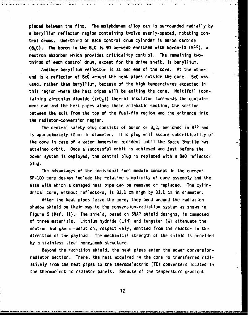
After the heat pipes leave the core, they bend around the radiation
shadow shield on their way to the conversion-radiation system as shown in
Figure 5 (Ref. 11). The shield, based on SNAP shield designs, is composed
of three materials. Lithium hydride (LIH) and tungsten (W) attenuate the
neutron and gamma radiation, respectively, emitted from the reactor in the
direction of the payload. The mechanical strength of the shield is provided
by a stainless steel honeycomb structure.
Beyond the radiation shield, the heat pipes enter the power conversion-
radiator section. There, the heat acquired in the core is transferred radi-
atively from the heat pipes to the thermoelectric (TE) converters located inthe thermoelectric radiator panels. Because of the temperature gradient
12

CORE HEAT PIPE
TUNGSTEN __.w -iSTAINtLESS STEEL
MATRIXC' ONTROL aRt••
JA _bi
REACTOR CORE
_j_ ,eNTRAL PLUG
- RADIATION SHIELD ACTUATOR
Figure 5. Axial cross-sectional diagram through the SP-100reactor core and radiation shield.
across the semiconductor material of the TE converters, a voltage drop Iscreated, and, with a complete circuit, the thermal energy is partially(-6.8 percent) converted into electricity. The rest of the heat (-93.2
percent) must be radiated into space from the cold side (outer surface) ofthe radiator panels. Specific details of the various design features of theSP-100 will be given in the remainder of this report and can also be found
elsewhere (Refs. 11-13).
13
N'

II. SP-100 DESIGN LIMITATIONS
This section reviews the status of the SP-100 design as of October
1982. The components of the design (the nuclear reactor core, the radiation
shield, the energy conversion system including the heat Mas, radiative
coupling, and radiator, as well as miscellaneous sy$t ,#= tiscussed.
This section emphasizes current design limitationsti cW• Mec with a
discussion of the technical developments remaini Wj V I before
fielding the present design.
1. NUCLEAR REACTOR CORE
As mentioned earlier, the core of the current SP-.. jesign Is a cylin-
der 33.1 cm in diameter by 33.1 cm high (not Including the reflectors) and
consists of 120 heat pipe fuel modules (see Fig. 4). The fuel, 93.1 percent
enriched U02 , is in the form of annular wafers (126 wafers per heat pipe)
sandwiched between Mo-13 percent Re fins integral to the heat pipe walls.
The fuel-fin region is 80 percent by volume of U02 , and 20 percent by volume
of Mo-13 percent Re (Ref. 13).
a. Fuel Material--Four types of fuel materials were considered for the
SP-100 reactor core: uranium carbide (UC-lO a/o ZrC), uranium dioxide (U02 ),
uranium nitrate (UN), and a uranium dioxide molybdenum cermet (U02 -40 per-
cent by volume of Mo). Table 3 summarizes various characteristics of these
fuel materials.
Uranium carbide was dropped from consideration for the following rea-
sons:
(1) It chemically reacts with molybdenum (the primary component of the
heat pipe wall material) at the core operating temperature of 1500
K. The production of molybdenum carbide (Mo2 C) (Ref. 1) may cause
significant changes in the thermophysical properties of the heat
pipe wall.
(2) Because UC is a chemically active agent, handling and manufactur-
ing processes of the fuel must be conducted under vacuum in a
glove box.
(3) Cladding is therefore required for UC fuel; this would increase
the weight of the system in three ways. First, the clad itself
14

~ c f- 0
IA.
4v.
-a
W c
15

adds extra weight. Second, more fuel is required for a critical
systm to make up for neutron losses due to absorption in the
cladding and decreased fuel density. Third, the shield will need
to be wider to protect the same cone angle and so will probably be
heavier.
(4) UC fuel has the highest swelling among the fuels considered (Ref.
15), followed by UN, U02 , and the cermet (see Fig. 6).
Uranium carbide, however, has a higher thermal conductivity and higher
uranium metal density than either UN or U02; consequently, UC allows higher
operating power densities and fuel burnup.
In spitp of its low swelling, UN was also rejected as the fuel choice
because of the requirement for a pressurized system to prevent the loss of
nitrogen from the fuel matrix. This would add weight and seriously compli-
cate the design of the reactor. Also, the technology for manufacturing UN
is not well established. Although the U02 -40 percent Mo cermet offers animprovement in thermal conductivity over pure U02 , it was rejected as the
fuel choice because of the extra weight of the molybdenum in the fuel
matrix.
The remaining fuel candidate is U02 , which has the lowest thermal con-
ductivity among the fuels considered. Since UO experiences only moderate
swelling and is chemically inert, cladding is not required. Also, the tech-
nology of fabrication processes for U02 is available through commercial
industries. In addition, most irradiation and operation properties of U02are well known from longtime experience with light water reactors (LWRs).
Because of these factors, U02 was judged to be the overall best choice forthe SP-100 core design. However, the emphasis on the development of a car-
bide fuel continues by the Carbide Fuel Development program at the Los
Alamos National Laboratory (LANL) (Ref. 16).
b. Fuel Swellin--The total amount of fuel (93.1% enriched U02) in the
core would provide 1600 kW(t) power from fission (assuming 190 MeV/fission)
for 7 yr. This results in an average burnup of 3.6 atom percent (-3.6
MWd/kg), and an average fission density of 8 x 10²⁰ fissions/cm3 over the 7yr of continuous operation (Ref. 11).
The current design is limited to the 1600 kWt power level by the
expected fuel burnup. The accompanying fuel swelling for the fuel
16

Lfl
C zw. ~z i IL
mm
LL.
CID
LL.
N N-
M% 3SVQ3idONI 3wnJAOA
17

temperature range of 1510 to 1730K (determined by requiring the inner wall
of the heat pipe evaporator to be at 1500 K) would vary from 6 to 14 per-
cent. These results are predicted based on integrating experimental mea-
surements performed by Zimmerman and Grando (Ref. 17). Thus, fuel wafers
and modules are designed with gaps to accomhodate this estimated swelling.
Figure 7 shows the swelling predictions used by the LANL group in their com-
puter modeling of the core (Ref. 17). One p;'eiction of the effects of fuel
swelling can be seen in Figure 8 (Ref. 18). In that figure the computedbeginning-of-life (BOL) and end-of-life (EO0) longitudinal cross sections
through heat pipe modules are compared.
In the reference SP-100 design, the heat load is radiatively trans-
mitted from the entire condenser length of the heat pipes to passive thermo-
electric converters. Without changing the size or number of fuel modules in
the core, an increase in core power will necessarily mean an increase of the
heat pipe temperature and, therefore, an increase of the fuel temperature
and burnup. Since fuel swelling increases with both temperature and burnup,
increasing the core power in this manner will increase fuel swelling. As
can be seen in Figure 8, such swelling can produce stresses in the heat pipe
wall. These stresses could eventually lead to a heat pipe failure, either
by cracking the containing tube wall, allowing the escape of the lithium
working fluid, or by destroying the contact between wick and inner heat pipe
wall. The predicted fuel swelling and the effectiveness of the gaps to
accommodate it could be verified in in-pile testing of a heat pipe fuel
module which was planned in the Experimental Breeder Reactor (EBR-II) at
Argonne National Laboratory in Idaho Falls, Idaho.
c. Criticality Safety--The current safety guidelines require that the
SP-100 reactor be subcritical in the event of a launch abort that leads to
the reactor's being completely immersed in and all voY'e. filled with water.To satisfy this requirement, the current design incluoes a central plug of
neutron absorber (810 or B 10C, 7-cm diameter) which will be removed and
replaced by a BeO reflector plug once the Space Shuttle has attained orbit.
Recent calculations by LANL indicate that with the boron-l0 plug inserted
and the reactor totally immersed in water, the reactor is 86 cents
#
18

10�ft
0 0 0 0000 00 0 0 0�Q� 0 E- 0 d� 0P F'- 10 ' .0c�j N - -- - - -
+ 4' 4 ** ft ft ft S ft�v�* ft ft ft '4-ft ft ft ft ft* * ft S* ft ft S ft�* ft ft ftft ft ft c* ft ft* ft ft 'U* ft ft* 5 ft *
ft ft ft ft ft* ft ft 45
ft ft I.in =
ft ft .4.5ft ft 45* 'a
ft ft ft ftft ft ft ft
ft ft ft ft
* I'ft.
* * ft . A a* ft ft.-
ft. ft. ft - � 4-aft * 'ft Uft. 'ft
* I.-
* 'U
US* 'U
* N* C
ft�
in45
'ft - 3* ft ft ft In
ft ft ft ft ft* ft ft ft ft I-
ft ft ft a 45ft ft ftft ft ft ft ft
ft ft. ft ft ft ftft ft '4-ft ft S ft ft
ft ft ft ft ft ftft ft ftft ft ft In
ft ft ft ft ft
ft ft ftftftftftftftft�ftft ftft
ft ft ft ftft ft ft
p I I I�.
o 0 ifl 0 in aN N a -
(") 3SV3�NI 3flfllOAU-
19
*'ft *S . � %' �*S ' -A-. ', ft' ft ftft ft ft

I .....Iu4.4.
4g41
L 0L
4-'
000100%
000+4
000004-V
00 0000 0 00
0 0000 00
00 0 00 010 0 00 o
00CIia
W-
00%
I.e
20
*-' r' I N V

subcritical4 (Ref. 19). The calculation assumes that the reflector is in
place, that the control drums are locked into their control-in (safe) posi-
tions, and that water surrounds the reactor and is in all core voids,
including inside the heat pipes. In a hypothetical accident, other combina-
tions of events, such as removal (mechanical damage) of the reflector,
incomplete filling of the heat pipes with water, or the presence of absor-
bers in the water (i.e., salt water), would increase the safety of the sys-
tem with respect to unplanned criticality. The calculations of k-effective
were performed with a Monte Carlo (MCNP) code, which is accurate to within
three standard deviations (Ref. 20).
To better fulfill more stringent guidelines which may apply in the
future, the possibility of designing a reactor whose reflector will come off
either at launch abort or at reentry is still under consideration. In the
case of a water immersion accident, the boron-lO plug would provide a nega-
tive reactivity to a bare core of almost $3W, which is a very safe configu-
ration.
2. RADIATION SHIELD
The shield design is based on the LiH-stainless steel shield designs
developed in previous SNAP and ROVER programs (Ref. 13). The location of
the Shlold is shown in Figures 2 and 5. A reference shield was designed to
atte , the 7 yr neutron fluence to 1012 n/cm2 and the 7 yr gamma dose to106 rd at an unmanned payload location 25 m from the center of the core
(Ref. 12). The area protected by such a shield is 150 m2 of circular area
perpendicular to the line of sight to the reactor. This requires a shield
cone-angle of 30 deg. Neutron attenuation is provided by the LiH, while
gamma attenuation is provided by the tungsten (W) plus the stainless steel
honeycomb structure in the LiH shield.
The mass of the reference shield, 790 kg, is 28.5 percent of the total
system mass of SP-100. Unlike design constraints imposed on the core and
4 Thls is based on a value for s, the delayed neutron fraction for U235
fast fission, of 0.0165 (Ref. 21).
SA dollar worth of reactivity is the amount of reactivity equal to the
effective delayed neutron fraction, s.
21
.... . . . . .. . . .W . .. . . . . . . . . . . .

heat pipes by fuel swelling and wicking limit power, respectively, the
shield mass is not firmly limited to this 790 kg. Because of the high
launch cost per unit mass, minimal mass is a prime consideration for space
power systems. Since the shielding requirements are highly mission depen-
dent, ways to reduce shield mass can be investigated, once the specific use
of the SP-100 system is determined. Examples of ways to reduce the required
shield mass are as follows:
(1) Move the payload farther away from the reactor.
(2) Configure the payload so that it subtends a smaller solid angle.
(3) More accurately determine the radiation limits of payload compon-
ents to see if perhaps larger dose rates could be tolerated.
(4) Individually shield the most highly radiation-sensitive parts of
the payload.
(5) Better determine the attenuated spectrum and any spectral depen-
dence of radiation damage to the payload so that perhaps only
spectrum specific shielding would need to be provided.
(6) Determine more exactly the lifetime, power levels and power utili-
lization factor required by the particular mission, so that the
shielding mass can be reduced accordingly.
(7) Develop new shielding materials (alloys or metallic composites)
wtich are light in weight.
3. ENERGY CONVERSION SYSTEM
The energy conversion system consists of the core heat pipes, the
thermoelectric converter modules, and the radiator panels. This section
reviews the design features of those system components with comments on the
design limitations of each.
a. Heat Pipes--The current SP-100 core design uses 120 heat pipes made
of an alloy of molybdenum and rhenium (Mo-13 percent Re) with lithium as the
working fluid. The design power of each heat pipe is 15 kWt. However,
there is some variation in the amount of power that can be carried by each
pipe (1600 kWt/120 heat pipes - 13.3 kWt/pipe average) (Ref. 13). Thus,
some allowance for possible heat pipe failure exists. If 13 heat pipes were
to fail and if the 1600 kWt were evenly distributed among the remaining heat
pipes (107 in total), they would still be operating slightly below their
design power of 15 kWt.
22
.. . . . ..i . • '-"" ..• .'- ".' '. . •"- "' .•. , .- ' ""''-"''' • --.''-.-2..-.• '.. '' ..• 'Ž i rk , . Yv' . C•• 2 ". " L-•''': ... .. .A . . " . . . .. ."• . .. . ... . .- ,•. . . .. .. -• • ." .' .... .-. .... .... .... .... .. . .

To determine the actual heat pipe design (diameter, type, and dimen-
sions of wick, screen pore size, etc.), a factor-of-safety of 1.5 Is applied
to the design power of the heat pipe (Ref. 22). Thus, the design chosen has
a theoretical maximum power of 22.5 kWt, which is the wicking limit at 1500
K. If all heat pipes in the SP-100 core were operating at their wicking
limit, they could carry 2400 kWt of power out of the core.
Besides the amount of power to be transported, other considerations
affect the choice of heat pipe wall thickness and number. Reliability and
quality assurance, with a factor-of-safety of 2 applied, required a wall
thickness of 0.75 rom. Although the mass is minimized with about 45 heat
pipes, such a low number of heat pipes would cause the consequences of a
single heat pipe failure to be more severe. Because fewer heat pipes also
necessitate larger diameter fuel wafers, such a design would force higher
fuel temperatures, thereby substantially increasing fuel swelling. Taking
all of these considerations into account, a reference design of 120 heat
pipes was chosen (Ref. 22).
b. Radiative Coupling--The previous SPAR and subsequent SP-100 design
called for thermoelectric converters to be in physical contact with the
condenser ends of the heat pipe. Such conductive coupling has been replaced
in the current SP-100 design with radiative coupling between the heat pipes
and thermoelectric converters in order to add redundancy in th'3 heat flow
path.
With conductive coupling, for example, failure of a heat pipe causes
the string of TE converters in contact with it to cease producing electri-
city. With radiative coupling, on the other hand, each thermoelectric con-
verter receives radiant heat from a large number of heat pipes. If a heat
pipe fails, the remaining heat pipes could still carry all the power from
the core and radiate it to all of the TE converters. Therefore, with radia-
tive coupling, all TE converters would still be operable with one or more
heat pipes inoperable.
Additional advantages of radiative over conductive coupling are the
following:
(1) Radiative coupling allows design of the radiator-energy conversion
subsystem to proceed relatively independently of the design of the
reactor-heat pipe subsystem. Thus, the work on the
23

radiator-conversion subsystem is not so dependent upon the designstatus of the core and heat pipe subsystem. 6
(2) The conductive coupling system requires an additional set of heat
pipes to transport waste heat to the radiator. Use of radiative
coupling avoids this completely.
(3) Power flattening in the core is less critical since single heat
pipe failure does not lead to lossof that fraction of the core
power output.
(4) No electrical insulator is needed between the hot shoe of the
thermoelectric converter and the heat pipes, as it was in the
conductive coupling design.
(5) The waste-heat radiator is not as vulnerable to meteorite damage
as the heat pipe radiator of the conductively-coupled system,
which contains thin-walled radiator heat pipes. Meteorite damage
to the heat pipe radiator could lead to loss of the heat pipe
working fluid, and a subsequent failure of a sectior, of radiator
panel. Meteorite puncture of the radiatively-coupled radiator
panels does not significantly alter their operational chara,-ter-
istics.
(6) In the conductively-coupled design, overheating of the electrical
insulator between heat pipes and TE converLers could cause signi-
ficant alteration of the thermal conductivity of the material.
This problem does not exist in the radiative coupling design.
Disadvantages of radiative coupling (Ref. 11) as compared to conduc-
tive coupling are:
(1) Higher fuel and heat pipe temperatures are required to radiate the
same amount of heat. These higher temperatures lead to greater
6 1t should be noted that there are certain pitfalls associated with theindependent design of two or more subsystems. A specific example of thekind of problem designers of independent subsystems may encounter can begiven for the SP-100 design (Ref. 23). The total SP-100 system weight forvarious configurations (Ref. 12) was obtained by adding the LANL-derivedminimized reactor/shield mass to the Jet Propulsion Laboratory-derivedminimized radiator/converter mass. The procedures for minimizing mass of asubsystem include optimizing the number of heat pipes used. Thus, for thepower systems whose specific masses are given in Ref. 12, the number ofheat pipes leaving the reactor core for a minimized reactor/shield mass maynot be equal to the number entering the radiator region for a minimizedradi ator/converter mass.
24

-mchanical stresses to the heat pipes and structure in the reactor
core (caused by increased fuel swelling, increased creep rates,
etc.).(2) -High-emtssivity_(¢ = 0.85) surfaces on the heat pipes :and hot
shoes are necessary, requiring further technology development.
(3) Longer heat pipes (-8 m) are required to provide the area for
radiating the design power at an emissivity of 0.85. Longer heat
:pipes are likely to be more difficult to fabricate and to start up
thermally. In addition, it is not known if the extra length of
the heat pipes will affect their reliability and lifetime.
(4) Increased fuel temperature increases the possibility of fuel-
migration, a further limit on the core lifetime.
c. Thermoelectric Converters--The primary development problem for the
thermoelectric converters relates to obtaining higher energy conversion
efficiencies. For a given electric power output, small improvements in
efficiency can lead to dramatic weight savings in the radiator system. The
development of new thermoelectric converter materials with high performance
is complicated by the requirement for long lifetime operation in the radia-
tion environment expected for the SP-100. The thermal and vacuum environ-
ments couple to require a durable coating in order to minimize TE material
sublimation over the expected operating history of the system.
d. Conversion Efficiency--The conversion efficiency, n, of a thermo-
electric converter material (Ref. i), is approximately defined by
n Z AT (1)
where AT is the temperature drop across the converter, and Z is the figure-
of-merit for the converter material. 7 The figure-of-merit, Z, is defined
by
S ap- a 2(2)
7A more accurate empirical formula for n, which included temperature depen-
dence, was used by JPL for the converter design calculations (Ref. 23).
25

where a, p, and k are the Seebeck coefficient, electrical resistivity, and
thermal conductivity of the semiconductor material, respectively. The sub-
scripts n and p refer to n-type and p-type material. Since the material
properties a, p, and k are all strongly temperature dependent (Ref. 1), the
conversion efficiency of a given thermoelectric material is highly tempera-
ture dependent. Figure 9 displays the theoretically derived variation of Z
with temperature for various thermoelectric materials (Ref. 1).
The efficiency value of 6.8 percent assumed for the SP-100 design
assumes the use of a converter material with a z value of 1.0 x 10⁻¹ K-1
at 1350 K. Such a material is not yet available (Ref. 12), although the
SiGe + (Gallium phosphite) GaP is within 20-30 percent of that value. It is
noteworthy that in the present design a space is available between hot and
cold shoes for larger TE converters, as can be seen in Figure 10. Thus a
100 kWe system could be designed without any extrapolation of known thermo-
electric converter technology. Such a design would, however, require a
somewhat larger core thermal power and higher radiator area. Upon optimiz-
ing these parameters to obtain the 100 kWe output desired, the currently
available TE material would lead to a 20 percent increase in the mass to
power ratio of the SP-100 (Ref 12).R
e. Converter Sublimation--Another design limit of the present SP-100
system is the expected durability of the sublimination coating required by
the TE converter. Without such a coating, a significant amount of the TE
material would sublimate at the hot junction temperature of 1350 K during
the 7 yr operating lifetime. However, a vapor suppression coating which is
known to work under these conditions is not yet available for the SP-1 0 0 q
(Fig. 11).
aThe curves in Figure 9.1 of Ref. 12 are somewhat deceptive because they donot match the design value of specific weight quoted earlier in that text.Those curves should be adjusted downward to match that value of 27.7kg/kW(e) as should others which follow in the text.
9 Recent testing of S'02 as an anti-sublimation coating is described in Ref.24. This yields an improvement over the material previously used for thatpurpose, Si0N4. Figure 11 shows the data obtained for the SiO2 coating ata temperature of 1323 K for 2500 h. The researchers interpreted the suddenincrease in sublimation near the end of the experiment as an effect of con-tamination of the coating by volatiles (possibly the TE material itself).It is hoped that vacuum firing of the coating for future tests will elim-inate this problem (Ref. 24).
26

' !1 €
•. '2 /•:) . .
"-- .E •-?
; • aJ
" I € u ',T
' 1;•: °0 •
_ I
|1
I I I I-" • • •
": ' •.an6 •:I
Sl.aaH-..I.O-
.'•
g7
,-

U,
L
III I 4.'U
C0I a.S
S. z C0
2 U'-I
-.5z.5 1.
U II II 0I I
LW I ."�:
p. '��2 a'.5 H La�
Up
z1*.* Qo
I.,
-�
28

CJ,
41
0 04
Lnn
4-)
L..
enn
C9 .=1ý 1CD C C.) CD C
z W3/6u) SSO 4460
29C

The conversion efficiency of a TE material is directly proportional to
the temperature drop across the junction. Assuming emissivities of 0.85,
the temperature drop achieved across the converter depends on the thickness,
surface area, and thermal conductivities of the hot and cold shoes and of
the TE material. The JPL code for optimization of the iE energy conversion
includes the ability to vary the area and thickness of the converter to
minimize system mass (Ref. 23). The minimal mass requirement along with the
assumed material properties at the operating temperatures of the radiator/
converter limit the overall thermal-to-electric conversion efficiency of the
subsystem to the 6.8 percent previously noted.
f. Radiator--The waste-heat radiator design uses a carbon/carbon com-
posite (theoretical emissivity, E - 0.85), which has an area of 70 m2 . With
its average operating temperature of 800 K, it would radiate 93.2 percent of
the heat that reaches the radiator-conversion system to outer space. This
assumes tnat the view factor to outer space at a temperature of 0 K is 1,
which certainly is not always the case, since possibly the earth, the moon,
and the sun subtend part of the solid angle seen by the radiator. Correc-
ting for this effect slightly lowers the amount of heat which can be
radiated.
In outer space, waste heat cannot be rejected by conduction or convec-
tion, as on earth. Instead it is removed by radiant heat transfer. The
quantity of heat that can be exchanged radlatively between two objects in
space depends on their tempeatures, surface dreas, and the solid angles sub-
tended by each surface at the other surface (shape factors).
In space, the heat sink would be the empty space and nearby objects,
such as the sun dnd the earth. The waste heat radiator of a satellite in
the vicinity of the earth would receive about 1400 W/m2 of direct solar
radiation, about 420 W/m2 of solar radiation reflected from the earth, and
about 243 W/m2 of earth-emitted radiation, as worst case estimates (Ref.
1). If the radiator's absorptivity to solar radiation is 0.21 and its
absorptivity to earth-emitted radiation is 0.85, radiation from the sun and
earth providing additional heat load to the radiator of (1400 + 420) x 0.21
+ 243 x 0.85 - 590 W/m2 . Because the radiator is conical, less than half of
its surface "sees" the sun or the earth, a better worst-case estimate is
half of this amount (590 W/m2 ) or approximately 300 W/m2 . Since the SP-100
30

radiator area is 70 v2 (Ref. 12), this represents a total heat input of 21
kWt. Thus, the radiator's heat rejection capacity must be the 1370 kWt of
waste heat from the power conversion process plus the 21 kWt of absorbed
radiat ion from the sun and the earth. This extra 21 kWt represents a
radiator temperature increase of approximately 3 K.
4. CONTROL DRUM ACTUATORS AND REFLECTOR
An important subsystem of the SP-100 is the actuator control system.
The actuator controls the startup, scram, and power level changes of the
reactor by rotation of the 12 control drums. For high reliability, the
actuator should be simple to operate and should be able to function
properly even if several drums are inoperable.The detailed design of the actuator control system for the SP-100 has
not yet been done. It is to be based on those designed for the SNAP program
(Ref. 11). The controls will be on the payload side of the radiation shield
(see Fig. 5) and must be able to withstand the same radiation doses exper-
ienced by the TE converter.
The design of the Be reflector is limited by the requirement that its
temperature be kept below approximately 900 K. At temperatures higher than
this, significant swelling of the Be occurs (Ref. 11). Gaps left between
the Be reflector and the control drums must be large enough so that after
the expected swelling of the Be and of the B8C of the control drums, the
control drums are free to turn when actuated. It is desirable, however,
that these gaps be as small as possible to minimize neutron leakage, thereby
minimizing the reactor fuel mass.
It is expected that the reflector will be cooled by radiation to outer
space. To prevent overheating of the reflector by conduction from the core,
thin, lightweight multifoil thermal insulation"0 will be used between the
core containment can and the reflector. Most heating of the reflector is
expected to be from neutron and gamma radiation (Ref. 11). The second
largest heating source is expected to be from conduction through the core
mounts at the top of the core. Ceramic blocks (ZrO2 ) are to be used there
as thermal insulation. A preliminary thermal analysis by the LANL design
100f the type made by ThermoElectron Corporation, Waltham, Massachusetts.
31

team indicates that such insulation should be sufficient to keep the Be
temperature below 900 K (Ref. 11). A more rigorous analysis, which includes
the decrease in thermal conductivity of the beryllium with neutron irradia-
tion and the possibility of a failed heat pipe near the core mount, should
be done to insure that swelling of the beryllium will not lead to inoperable
control drums.
32

III. ADDITIONAL RESEARCH AND DEVELOPMENT
Although the SP-1.00 is in an advanced state of concept development,there are a number of important aspects of that design which require addi-
tional research and development. The purpose of this section Is to identify
those areas of research which might lead to substantial design revisions.
In the area of nuclear core design, fission gas and its volatile release andfuel migration have been identified as possible causes of core can pressuri-zation and subsequent mechanical failure, and are worthy of additional
study. With respect to heat pipe development, there is the problem of prop-agation of single heat pipe failure through transient thermal stresses and/or lithium and fission product contamination to be considered. In addition,the heat pipe development area still suffers from (1) lack of fabricationtechnology for long pipes, (2) little understanding of the effects of theradiation environment on heat pipe operation, and (3) lack of long-life,high-emissivity coating technology. The present design of the radiation
shield has poorly understood thermal characteristics and requires furtherdesign. Other areas of concern are the assurance of criticality safety, thetechnology of producing thermoelectric converters that can withstand thesevere radiation and vacuum environment, the effects in the control drums of
self-welding, and the need for the reflector and mechanical actuators to be
functional in the SP-100 environment.
1. NUCLEAR REACTOR COREFuel Swelling--The nuclear reactor core is designed to accommodate
6-14 percent fuel swelling (Ref. 25). Swelling beyond this limit could leadto a heat pipe failure. As the wafer swells axially, it causes the pipeto deform (see Fig. 8 for details of the geometry). Depending on the elas-tic behavior of the Mo-13 percent Re alloy under stress, cracking canoccur. This alloy's ductility, however, may be modified by the irradiationhistory and the thermal cycling which it would experience.
The predicted amount of fuel swelling depends on the interpretation ofavailable data and the application of the data to the SP-100 fuel design(Refs. 15 and 25). No tests have been done on unconstrained fuel wafers ofthe size and shape of those of the SP-100, in a fast neutron flux and at the
33

expected SP-100 fuel temperature. The amount of fission gas release depends
on the fuel temperature and fuel burnup and to a lesser extent on the grain
size, and on the geometry and methods of preparation of the fuel wafer
(Ref,. 26). One mechanism of swelling is the presence of gas molecules with-
in the fuel and the formation of interstitial gas bubbles. This includes
both volatile and gaseous fission products and helium produced by (n,a)
reactions. It should be easier for these gases to be released at low pres-
sure and a high surface-to-volume ratio, presumably resulting in reduced
fuel swelling. Such a result for the SP-100 operational parameters needs to
be verified by experiment.
Although the 1.3 yr in-pile testing of a fuel module in EBR-II will not
exactly simulate SP-100 operating conditions (Ref. 11), it should provide
useful data to verify the amount of swelling expected. In addition,the
EBR-II testing should give some indications of correct void placement to
accommodate fuel swelling and may also suggest modification of subsequent
in-pile testing.
a. Vented Gas Gap--Another area for further investigation is the
modeling and design of the vented gas gap between fuel modules and the sub-
sequent venting into outer space (Ref. 27). The current design calls for a
0.8 mm spacing between the fuel modules. The purposes of the gap are:
(1) To make assembly easier,
(2) To allow room for fuel swelling,
(3) To ensure that the core will easily break apart, burn, and dis-
perse upon atmospheric reentry (Ref. 28), and
(4) To allow for fission product (gases and volatiles) release and
venting into space.
The Mo-13 percent Re core containment can (see Fig. 4) was not designed
as a pressure vessel. It has been described as sufficiently leaky so that
fission product gases released into the gaps will be vented into space and
so that the approximate pressure in the gaps is zero (Ref. 29). The SP-100
design team also expects that some fuel may be lost over the 7 yr reactor
lifetime to space via the gaps by sublimation (Ref. 29). Although designers
suggested that the vents be placed at the exits of the heat pipes from the
core, there are a number mf design flaws associated with this treatment of
fission gas and volatile release In the SP-100 design.
34

As the heat pipes exit the core, they will be insulated from the sur-
rounding BeO reflector by multifoll. The presence of this multifoil will
interfere to some extent with the release of gases to space via this route.
Sme build up of f ission gas pressure within the core is necessary in order
to provide the gradient wich drives the fission gas flow to the exhaust
vents. After the beginning of reactor operation, this state of gas produc-
tion and flow will produce a varying internal pressure. The magnitude of
this internal pressure will be determined by:
(1) the rate of release of fission gas and volatiles, as well as the
fuel vapor, from the fuel surfaces, and
(2) the rate of gas discharge, which is In turn dependent on
(a) cross-sectional flow area at the exits,
(b) fuel gap and structure temperatures,
(c) frictional resistance offered by the flow path, as well as
(d) kinematic viscosity of the gas mixture.
It is yet to be determined that this pressure will be low ennugh not to
cause structural damage tn the core, in particular to the structurally weakmultifoil insulation (witich is to reduce tiermal losses from the core and
from the heat pipes along their adiabatic section to less than 9 per-
cent). 1 1 An engineered venting system may be needed in order to maintain the
internal pressure required by the mechanical structure and prevent potential
plugging of the system.
Beyond modeling the steady-state internal pressure in the core, two
other analyses related to venting fission gases should be considered. Oneis to investigate the effect on core pressure of closing of the gas gaps
with time because of fuel swelling. The other is an analysis of the possi-
bility of plugging of the vents due to the freezing and redeposition of fis-sion volatiles on the vent walls. Since the temperature of the vents to
space is significantly lower than the temperature of the core, the exit
temperature is likely to be below the condensation temperature of most ofthe fission volatiles. The continuous deposition of fission products on thevent wall will restrict the exits and cause an Increase of core internal
pressure with time.
""iThe power produced in the core is 1600 kWt. The power entering the con.verter radiator region is 1470 kWt (Ref. 11). Thus, the thermal lossfactor is 0.081.
35

Larger gaps and vents could be added to tie SP-100 design, in order to
assure adequate venting of the fission gases. However, enlarging the gaps
and vents would increase neutron leakage and so may necessitate additionalfuel, which would increase the system's weight. An alternative is to model
the complicated dependence of internal core pressure on the characteristics
of gap and gases, including the effects of deposition. This design problemshould be examined in greater detail.
Another area of concern which has received little treatment in the
SP-100 design is the effect of the fission gas cloud released from the reac-
tor. The fission gases and volatiles vented from the reactor would expand
outward in the vacuum surrounding the system. Most such fission products
would escape the local environment of the reactor system and produce no fur-
ther effects. However, that fraction of those volatiles with trajectories
back toward the radiator and payload could condense onto available surfaces.
The additional radiation burden of these volatiles could cause damage over
time. Although the low exhaust temperature would likely prevent it, some of
these fission volatiles could possibly become charged. If this occurs,
those charged volatiles and gases would not depart from the reactor system
and could form an electrostatic cloud remaining with the system. Such pos-
sible effects should be seriously considered in the application of a ventedreactor, such as the heat pipe reactor, to a manned space station.
b. Heat Pipe Failure--A heat pipe failure may impact the core in at
least two ways. There is an immediate increase in the fuel temperature in
the vicinity of the failed heat pipe, leading to increased fuel swelling and
sublimation. In addition, there is possible contamination of the fuel and
structure by the lithium which leaks from a damaged heaL pipe, leading to
material property modification. Each of these effects can increase the
likelihood of subsequent heat pipe failure.
c. Failure Propagation--The temperature rise near a recently failed
heat pipe depends on the extent of the coupling between the fuel wafers and
the fins of the failed heat pipe and also between that fuel module and the
neighboring fuel modules. A combination of fuel swelling and UO2 deposition
on the fins could alter the thermal characteristics of the failed module
.W
p 36

and Its ability to keep the temperature rise small. 12 Although only a
small temperature rise Is a possibility under such conditions, it is
expected that there will be a substantial temperature rise. Higher fuel
temperatures of the failed module and surrounding modules will lead to
increased fuel swelling and increase the likelihood of failure of the sur-
rounding heat pipes. There has been considerable work by the SP-100 design
team on this problem, and the team has concluded that failure propagation
would be at an Kcceptable level for the lifetime desired for the system.,
Nevertheless, further work should emphasize the importance of this problem.The temperature rises that occur when a heat pipe falls must not lead to a
propagation of that failure to other heat pipes.
d. Lithium Contamination--Because lithium is chemically active, it
will combine with oxygen from U02 in the core, thereby reducing the U02 to
uranium metal. Because the melting point of the uranium metal (1405 K) is
lower than the fuel operating temperature (>1500 K), regional melting of the
fuel will occur if uranium metal is present. Such melting and possible fuel
reconfiguration may change the power profile and disturb the operation of
the core. In a zero gravity vacuum environment, melted fuel would tend to
densify and clump, possibly leading to a reactivity excursion. Fuel melting
could lead to closing of the vent gaps and reduced fission gas release. In
turn, such pressurization could lead to enhanced fuel swelling and possible
mechanical failure of the core containment. Further work needs to be done
to determine the effects of a lithium leak in the core, and either to
mitigate such effects, or assure that the likelihood of a leak is very
small.
2. HEAT PIPE DEVELOPMENTThe heat pipes for the SP-100 reactor design are in the most advanced
state of development of any system component, other than the reactor core.
The outstanding issues presently receiving the bulk of the development
12 The BOL emissivity of the fins is only 0.3, but fuel deposition canincreas: that to a value as high as 0.8. That increased emissivity wouldlead to better radiant transfer with surrounding fuel modules. Similarly,fuel swelling could lead to better thermal conduction between fuelmodules.
37
S. *. . . .....J e J" * .JL-L. .L .L

effort are the fabrication of long heat pipes and the manufacturing of dur-
able, high emissivity coatings. In addition to reviewing the status in
those areas, this section discusses the research needed in relation to heat
pipe transient behavior and the effects of radiation on heat pipe operation.
Fabrication--The current SP-100 design calls for an 8-m-long heat pipe,
approximately 16 mm in diameter, made of Mo-13 percent Re. However, such a
heat pipe has not yet been constructed. The Mo-13 percent Re alloy chosen
for the heat pipe has only recently been acquired. Its physical properties
at high temperature have not yet been measured and have only been inferredfrom an interpolation between the properties of molybdenum and a Mo-40 per-
cent Re alloy. The design of an 8-m heat pipe in which the entire condenser
length (greater than 6.5 m) is certain to be active and which can be
reliably started up in space is yet to be done.
Once the 8-m-long heat pipe is designed, the fabrication, fill, and
testing processes remain. Molybdenum alloy tubing of consistent high qual-
ity is needed (Ref. 11). Although a number of such heat pipes have been
manufactured and tested, fabrication procedures for 2-m-long heat pipes are
yet to be perfected. Problems with bonding the distribution wick to the
heat pipe wall still must be solved. Drawing the tubing down onto the wick
has caused wick buckling and subsequent cracking. Expansion of the wick to
contact the wall has resulted in incomplete wick-wall contact. Each of
these effects results in a degradation of heat pipe performance. Fill pro-
cedures which prevent too high an impurity level have been accomplished for
2-m-long heat pipes, but these must be modified for 8-m pipes. Testingfacilities for 8-m pipes must be built, and it must also be ascertained that
bending the heat pipes will not significantly damage the wicking structure.
Reliability testing must also be done on a large number of such manufactured
7. heat pipes, prior to their use in a space environment.
"" b. Radiation Effects--The effects of neutron and gamma irradiation on
p. heatpipe performance are not well understood. Neutron irradiatio'i of the
lithium working fluid can produce helium.gas through an (n,a) reaction. The
seriousness of this effect depends on the fraction of Li 6 remaining in the
Li 7 -enriched lithium used as the working fluid. Such helium gas may plugthe wick, restricting the circulation of the working fluid, consequently
causing local dryout of the wick and failure of the heat pipe. The
38

irradiation of the working fluid may either enhance or suppress the forma-
tion of local vapor bubbles, but it is difficult to predict what will occur
without experimental data in the operational parameter regime. Irradiation
damage to the heat pipe and wick material could lead to swelling and to a
significant change in heat conduction and mechanical properties. Increased
brittleness could Increase the probability of material failure from stress.
Impurities (e.g., He gas) inside the heat pipe would degrade heat pipe per-
formance. Chemical ilnteractions.of fission products (such as Cs and I) with
heat pipe material could also modify the thermophysical properties of the
heat pipes and shorten their operational lifetime. Thus, there are a number
of areas of concern related to modified material behavior in the heat
pipes. The planned EB,-II lin-pile tests should give indications of the
magnitudes of these effects, but further analysis and modeling is also
recommended.
c. High Emissivity Coatings--A high emissivity coating for the conden-
ser section of the heat pipes has not yet been achieved. The emissivity of
molybdenum is 0.3, and the Mo-13 percent Re alloy of the heat pipes is
expected to be similar. The current SP-100 design assumes a heat pipe con-
denser emissivity of 0.85, requiring a dramatic Improvement in emissivity
over the material of the heat pipe wall. It is crucial that the high emis-
sivity coating which is developed remain bonded to the heat pipe wall and
maintain its high emissivity over the lifetime of the system. With SP-100
design parameters, this requires seven years of operation at 1500 K in a
severe radiation and vacuum environment. The technological task of design-
ing and testing such a coating is receiving further study by the SP-100
design teal.
3. RADIATION SHIELD
The design operating range of the LiH-stainless steel shield is 600-
680 K, a narrow range. The lower limit assures the reabsorption of radioly-
tically decomposed hydrogen. The upper limit avoids excessive thermal dis-
association and subsequent hydrogen loss if the casing is punctured by
meteoroids (Ref. 12). However, no significant thermal analysis of the
shield has been completed (Ref. 30). It is not known that the shield will
remain within the design temperature range. The shield will be heated by
V 19
tN" 3g.......

gwma and neutron radiation and cooled by radiating its heat to space. The
heat pipes bending around the shield (thermally insulated by multifoil) will
cut down on the radiation view factor. Heat balance calculations should be
performed to ascertain the operational temperature distribution in the
shield. If the temperature range is not that required for shield integrity,
then a cooling system must be designed and implemented for the SP-100
shield.
4. CRITICALITY SAFETY
According to design team computations, the SP-100 reactor is very safe,from a criticality accident point of view, when the reflector is notattached. For the most extreme water immersion or impact accident, a sub-
critical configuration seems assured without the reflector in place.
Although not a requirement of the current design, the design modification of
a separate reflector that could be easily attached seems desirable. The
Shuttle crew could perform such a procedure while they are removing the
central safety plug.
Final safety guidelines prior to launch of a reactor of the SP-100 typewill require quantitative assurance of criticality safety in the event of
high velocity impact or explosion type accidents. Such a requirement
assures safety in the event of an explosion of the space shuttle's external
tank. Although scoping studies in this area have been made (Ref. 20), a
rigorous analysis remains to be done. The SP-100 design team at Los Alamos
National Laboratory includes criticality safety with its mandate. Additonal
computations in the area of an explosive compression of the core are
underway there. The assurance of the nuclear safety of a reactor to be
deployed in space has an overriding importance to all involved in the
project.
5. THERMOELECTRIC CONVERTERS
The primary development problems remaining for thermoelectric conver-
ters are the achievement of the performance goals included in the SP-100design. TE materials need to be developed with higher figure-of-merit which
can withstand high radiation environments without substantial degradation.
Antisublimation coatings which also survive in such environments must be
40

developed. This is a primary research and development area of the JPL
design group.
6. CONTROL DRUM ACTUATORS AND REFLECTOR
These are examples of aspects of the SP-100 design that have received
little attention because the details are perceived to be straightforward
engineering tasks. Examples of areas worthy of further study are: (1) a
thermal analysis for the reflector and actuators in order to ascertain that
thermal expansion will not lead to binding of the control elements (rotating
drums); (2) a study of the self-welding phenomenon and its effect on the
performance of the control drums; and (3) a complete design of a control
system which is operable in the high radiation environment of the SP-100.
Lq , 41KI

IV. CONCLUSIONS
This report reviews the status of the SP-100 heat pipe space nuclear
system design as of October 1982. The following components of the design
% are discussed: the nuclear reactor core, the radiation shield, the energy
. conversion system including the heat pipes, radiative coupling and radiator,
and miscellaneous systems. Current design limitations have been emphasized
and those technical developments which remain to be achieved prior to the
fielding of the present design have been reviewed.
Although the SP-100 is in, an advanced state of concept development, a
number of important aspects of that design require additional research and
development. This report identifies research areas which might lead to sub-
* stantial design revisions. In the area of nuclear core design, fission gas
and its volatile release and fuel migration have been identified as possible
causes of core can pressurization and subsequent mechanical failure as
worthy of additional study. Also identified, with respect to heat pipe
development was the problem of propagation of single heat pipe failure
through transient thermal stresses and/or lithium and fission product con-
tamination. In addition, the heat pipe development area still suffers from
"lack of fabrication technology for long pipes, from little understanding of
the effects of the radiation environment on heat pipe operation, and from
lack of long-life, high emissivity coating technology. The present design
of the radiation shield has poorly understood thermal characteristics and
requires further design. Other areas of concern are the assurance of criti-
cality safety, the technology of thermoelectric converters to withstand the
severe radiation and vacuum environment, and the need for the reflector and
mechanical actuators to be functional in that environment.
In summary, the SP-100 design is the most advanced of any nuclear reac-
tor for space power applications presently being considered. However, a num-
ber of design features will continue to require substantial technology
development before the system can be considered for deployment. Areas pre-
sently receiving programmatic emphasis include:
(1) Heat pipe design, fabrication, and testing;
(2) High emissivity, long-lived coating development;
(3) Nuclear fuel module design and testing;
(4) Criticality safety; and,
42

(5) Thermoelectric converter development.
Areas deserving additional research effort in order to support contin-
ued SP-100 development include:
(1) Modeling and testing ot beat pipe transient behavior and perform-
mance in a radiation environment;
(2) Modeling of fission product release and fuel vapor movement in the
SP-100 reactor core;
(3) Design of a system that allows adequate venting of the gaseous and
volatile fission products from the reactor core;(4) Analysis of the effects of material modifications caused by the
chemical interactions of fission products with fuel, heat pipes,
and structural materials;
(5) Analysis of the effects on heat pipe performance of fission-
produced impurities;
(6) Thermal and structural analyses of the radiation shield of the
SP-100;
(7) Additional analyses of the effects on control, drum operation of
material swelling and self-welding;
(8) Continued improvement of the conversion efficiency of the thermo-
electic converters;(9) Continued development of high-emissivity surfaces for the heat
pipes and radiators which will be stable in radiation and vacuum
environments;
(10) Additional analyses of the consequences of heat pipe failure,
including the effect of lithium contamination on the system
behavior; and
(11) Continued development of alternative radiator concepts for
enhanced system efficiency.
43

1. Budqn, David, et al., Selection of Power Plant Zlwlns for Futurepj~ý2r:§2M lectric ftstmr LA-798 Ui n XO =A1 tmionalltaa'
tory, Los Alamos, NM, Semer 1979.
2. Suden, David, "Overview of Spae Reactors,," lag Prime-powerConference, Norfolk, Virginia, February 1982.
3. Conies, w. R. and Swenk, F. C., Nuclear !Se3j for S , AnUnderstanding the Atom Series Booklet United States Atomic EnrgyCommission Publication, Library of Congress Catalog No. 79-171030(1968).
4. Gas Core Nuclear Rockets, United Aircraft Research Lab-.ratories Report,W767o.
5. McLafferty, G. M., "Gas Core Nuclear Rockets," Proceedings of ANS 1970Topical Mieting at Huntsville, Alabama (1970).
6. Masora, D. G., SNAP 8 Desi n Descri ption, NAA-SR-MEMO-8740, AtomicInternational, Canog Park, CA (1973).
7. Voss, Susan Schumacher, SNAP Reactor Overview, ANWL-TN-84-14, Air ForceWeapons Laboratory, Air Force Systems Command, Kirtland APB, NM, August1984.
8. Gietzen, A. J., et al., A 40 kWe Themnionic Powe e for aS_ O Laboratory, United States AtoiEnergy CmmiManton Contract#AT(04-3)-840, Gulf General Atomic, July 1971.
9. Rees, R. T. and Vick, C. P., "Soviet Nuclear Powered Satellites," J.British Interplanetary Society, 36, No. 1, 457-462 (October 1983).
10. Ivanovskii, M. N., Sorokin, V. P., and Yagodkin, i. V., The PhysicalPrinciples of Heat Pipes, Oxford University Press, New York (1M2).
11. SP-1OO Project Semi-Annual Technical Proess Review, Los AlamosNat l Laboratory, Los Alemos, NM, Otbr --.
12. SP-100 Cognetual Desijn Description, Jet Propulsion Laboratory,ena, CA, June
13. Semi-Annual SP-100 Desig Review, Los Alamos National Laboratory, LosAlamos, NM, April 13-15, 1982.
14. El-Genk, M. S. and Woodall, D. M., "Areas for Research Ziphasis in theDesign of the Space Powered Advanced Reactor," & Prime PowerConference, Norfolk, Virginia, February 1982.
15. Ranken, W. A., private communication, Los Alamos National Laboratory,Los Alamos, NM, November 1983.
44

16. Matthews, R. S. and Herbst, R. J., Uranium-Plutonium Carbide as LMFBRAdvanced Fu, LANLr-9259-MS, Los Alams Nat ional Laoratory,, LosAlmaos, R4, June 1982.
17. SP--10 Project Sani-Annual Technical Progress Review, presentation byW. A. Renken, Los Amos National Laboratory, !iM amk os, Wo, October
1982.
18. Semi-Anwal SP-100 Deig Review, presentation by Fairchild Industries,Na l at Los Almos, NI, April 1982.
19. Semi-Annual SP-1OO Design Review, presentation by Robert Bartholomew,Los Alamos Natioal Laoratory, Los Alamos, NM, April 1982.
20. Bartholomew, Robert, private cmaumnication, Los Alamos NationalLaboratory, Los Alamos, NM (1982).
21. Keepin, Robert, Physics of Nuclear Kinetics, Addison-Wesley, Reading,MA (1965).
22. Semi-Annual SP-1O0 Design Review, presentation by Karl Meier, LosAlamos National Laboratory, Los Alamos, 1M, April 1982.
23. Ell, Richard, private communication, Jet Propulsion Laboratory,Pasadena, CA, September 1982.
24. Noon, E. L., Progress Reort on Isothermal Testing of Silicon GermaniumCoated with SiOT Report 715-157, Jet Propulsion Laboratory, Pasadena,CA, zgut 1-9-.
25. SP-1OO Project Seal-Annual Technical Progress Review, presentation byW. A. Ranken, Los Alamo8 National Laboratory, Los Almaos, NM,October 1982.
26. Belle, J., editor, Uranium Dioxide: Pre tis and Nuclear Ahplica-tions, United States At nc IEiergy Cc 'i~ss16i, publishers, Washin~gton,DC (1961).
27. Louie, D. L. Y. and El-Genk, M., "Consequences of Venting SystemFailure in the Heat Pipe Space Nuclear Reactor," ProceediNs of 1st
AS4poalm on Sc Nuclear Power Systems, CONF-84-0113 (Eds. M. S.% -. k D. Hoover), R. Krieger lishing Company, Inc. (1985).
28. Meier, Karl, private communication, Los Alamos National Laboratory, LosAlamos, NM, August 1982.
29. Los Alamos National Laboratory SP-1OO Design Team, Informal discus-sions, White Rock, NM, July 1982.
30. Barattino, W., El-Genk, M., Voss, S., "Review of Previous Shield Analy-sis for Space Reactors," Proceedirgs of 1st Symposium on Space NuclearPower Systems, CONF-84-O113 (Eds. M. S. El-Genk and M. D. Hoover), R.*-KrIeger-P-b-lshing Company, Inc. (1985).
45/46


![by Rita M. Crow - DTICby Rita M. Crow DTIC ~EL ECTE 1 3 JAN 1989 DEFENCE RESEARCH ESTABLISHMENT OTTAWA TECHNICAL NOTE 88-22 Canada. lx,, b,. t pl ,,W June 198 n .,] d *r6 e Ottawa](https://img.pdfslide.us/doc/110x75/5f0f66447e708231d443f813/by-rita-m-crow-dtic-by-rita-m-crow-dtic-el-ecte-1-3-jan-1989-defence-research.jpg)