Embed Size (px)
Citation preview
Research and Development Technical ReportECOM-4008
0
•v SMALL RADAR CROSS SECTION MEASUREMENTS
ALLAN B. TARBELL
AUGUST 1972
• •., OCT le 9"
0
D0IS TR IBUT ION STATE.MENtT
SApproved for public release: R~eproduced by
• distribution unlimited. NATIONAL TE(CHNICAL• INFORMATION SERVICESU S Depofftment of Commerce
• Springf~eld VA 22151
0 0
UNITED STATES ARMY ELECTRONICS COMMAND" FORT MONMOUTH, N J

OlTIS t
jS C ................................. N 0 T I C E S, . ......... .. ...... . .. .. ..... ,......
BY . .. ..
CIS-,pguTI04/AVAILAD ILITY CODES
Disclaimers
The findings in this report are not to be construed as an
official Department of the Army position, unless so desig-nated by other authorized documents.
The citation of trade names and names of mhnufacturers in
this report is not to be construed as official Government
indorsement or approval of commercial products or services
referenced heroin.
Disposition
Destroy this report when it is no longer needed. Do not
return it to the originator.

UIEIASSIFMESecurity Classification -
DOCUMENT CONTROL DATA. R & D(Security classiticatlon of title, body of abstract end Indexlng annotatlon must bs entered when tMe overall report It claesfiled)
I. ORIGINATING ACTIVITY (Corporote author) 120. REPORT SECURITY CLASSIFICATION
US Army Electronica Command , LARSTF'TgFort Monmouth, New Jersey 2b. GROUP
3. REP•IOT TITLE
SMALL RADAR CROSS SECTION ME MENTS
4. DESCRIPTIVE NOTES (Type of report and Incluelve dates)
Technical Report5 AUTHORIS) (First name. middle initial, loot name)
ALLAN B. TARBELL
8. REPORT DATE 70. TOTAL NO. OF PAGES 17b. NO. OP RPFS
August 1972 10 1.So CONTRA(CT OR GRANT NO Se. ORIGINATORWS REPORT NUMERIS)
b.PROJETNO. js6 62704 A188 ECOM-4008
.Task N 01 b. OTHER REPORT NOi$) (A•n o•er nuwber that Imay be aeetelnodthls report)
d. Work ýit No. -171170 ISTI rTION STATEMiENT
Approved for public relcase; distribution unlimited.
II SUPPLEMENTARY NOTES 2. SPONSORING MILITARY ACTIVITY
US Army Electronics ComndAT!IN: AMSE,-CT-RFort Monmowth, New Jersey 07703
I1 AOSTRACT
Two methods of measuring radar cross sections as small as 10-10 m are described.The first technique utilizes the return signal from a doppler radar. The secondrelates radar cross section to variation in VSWR produced by the target when placedin a waveguide. These methods have been utilized to measure the cross section ofmosquitoes.
Results of these measurements at both X and Ku-bands are included. Calibrationtechniques are discussed for both methods of cross section measurement.
W 0101w PIC RPL CC$ 00 FORM 1471. I JAN 04. WHICH to
."oV6,IQ7r OOSIOLET O9roo ARMY Usa. tIELASSIFIED
I ty CIIsafiUcatiV

UNLASSIFIEDSecurity Classification
4. LINK A LINK a LINK CKEY WORDS .. - ,
ROLE WT ROLE WT ROLO £'r
Cross Section
X.,BandKU-Band
HISA FM 1997 - 72 tUNCLA.SIFITD
securty clasuification
Reports Coutrol Symbol OSD-1366
TECMCAL REPORT ECC0-4008
SMALL RADAR CROSS SECTION MEASLURMIS
by
ALLAN B. TAMULL
Radar Technical A-!eaCombo' Surveillance and Target Acquisiti.n Laboratory
August 1972
DA Work Unit No. is6 62T04 A188 01 171
Approved for public release;distribution unlimited.
UNITED STATES ARMY ELWCTRONICS CW4MAND, D'ORT MOI4MUTM., NEW JERSEY
il1
CONTENTS
Page
Abstract i
INTRODUCTION I
DOPPLER METHOD !
SWAVEGUIIWH-TIOD 2
CONCLUSIONS 3
FIGURES
1. Doppler Technique for Measuring 3=l Croso Sectiom 5
2. Calibration Curve (Doppler Radar) 6
3. Boxcar Detector Output Versus Time 7
4. Waveguide Method 8
5. X-Band Calibration Curve (Slotted Line) 9
6. Lu-Band Calibration Curve (Slotted Line) 10
TAKE
II. Peak-to-Peak Cross Sections Measmrinig Usvng the Doppler Method 4
ii
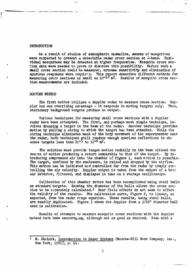
INTRODUCTION
As a result of studies of atmospheric anomalies, swarms of mosquitoeswere suspected to present a detectable radar cross section at Z-band. Indi-vidual mosquitoes may be detected at higher frequencies. Mosquito cross sec-tion data were needed to prove or disr,rove this possibility. Before such amall cross section could be measuree, extreme sensitivity and elimination ofspurious responses were requir,'. This report describes different methods formeasuring crors sections as small as 10-10 m2 . Results of mosquito cross sec-tion measurements are included.
DOPPLER METHOD
The first method utilizes a doppler radar to measure cross section. Dop-pler has one overriding advantage - it responds to moving targets only. Thus,stationary background targets produce no output..
Various techniques for neasuring =mall cross sections with a dopplerradar have been attempted. The first, and perhaps most simple technique, in-volves dropping a target in the beam of the radaA-. Another technique providesmotion by pulling a string to which the target hav been attached. While thestring technique eliminates much of the body movement of the experinenter nearthe radar, both techniques still pr9duce enough spurious reflections to ob-scure targets less than 10-5 to lO0 m2.
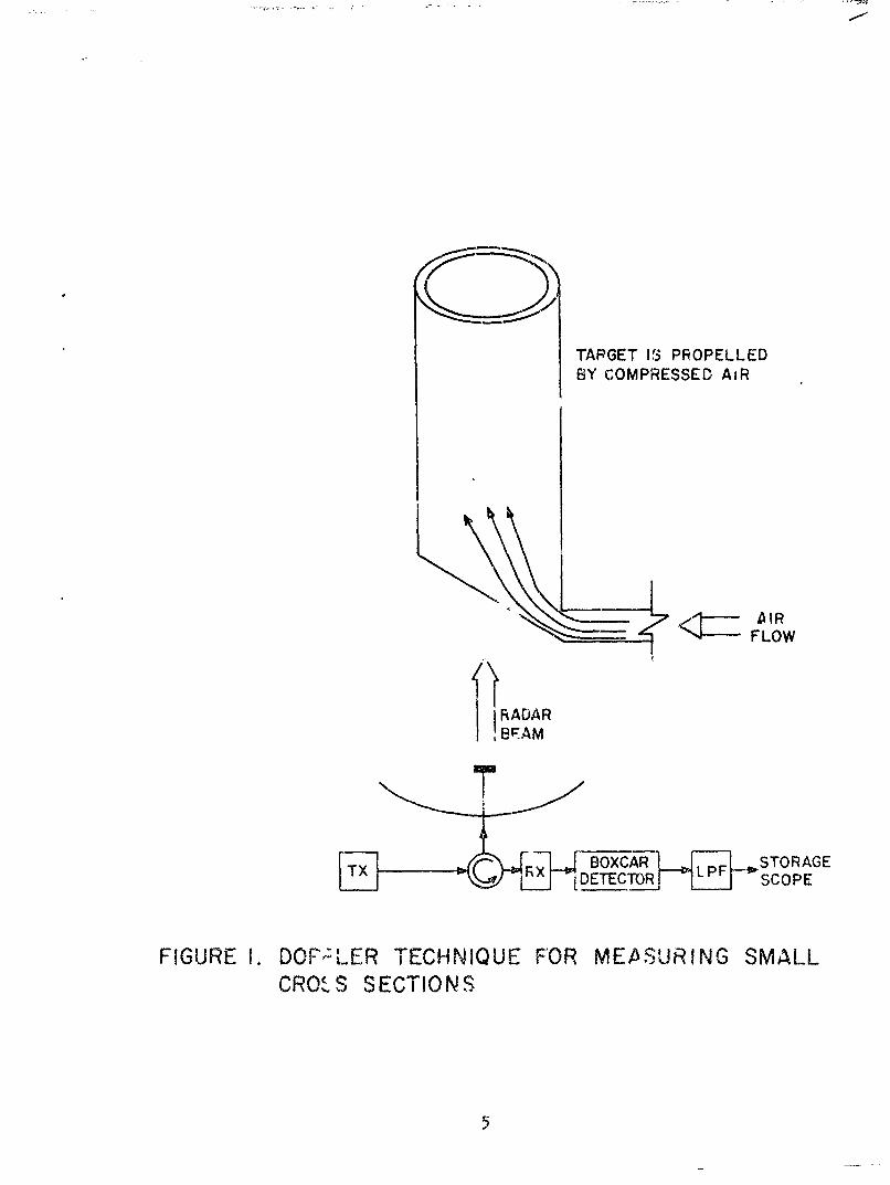
The solution must provide target motion radially in the bear. without thesou:ce of motion producing a return comparable to that of the target. By in-troducing compressed air into the chamber of Figure 1, such rvotion is possible.The target, confined by the enclosure, is raised and dropped by the airtiow.This motion can be initiated aa:d controlled far from the radar by simply con-trolling the air velocity. Doppler output is taken from the output of a ho'c-car detector, filtered, and displayed in time on a stora'e oscilloscope.
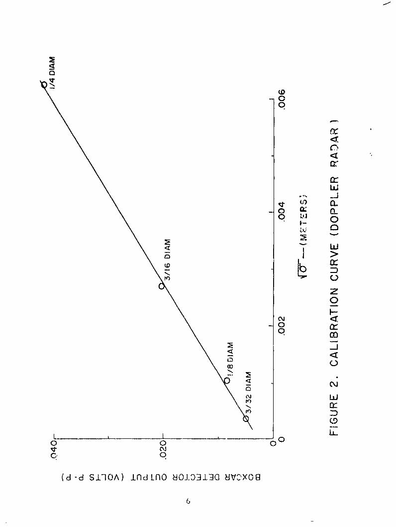
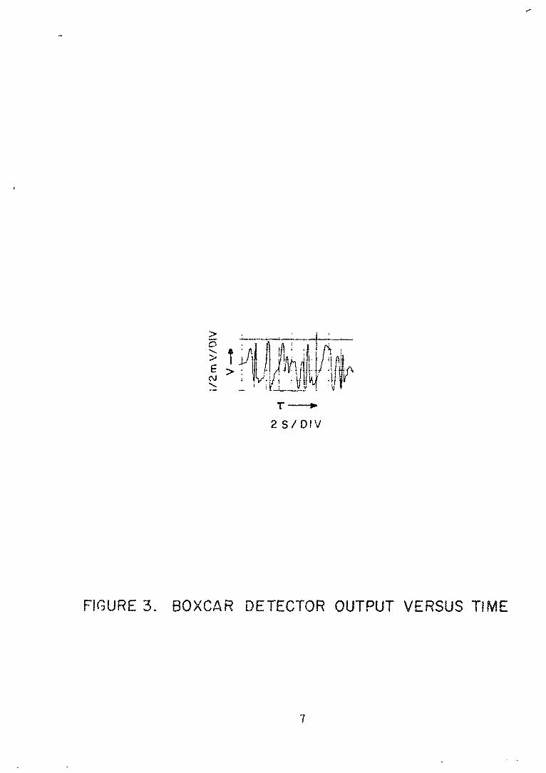
Calibration of this chamber device has been accomplished using steel ballsas stFndard targets. Knowing the diameter of the balls allows the cross sec-tion to be accurately calculated. 1 Near field affects do not seem to affectthe validity of the results. The calibration curve, Figure 2, is linear, asexpected, from the radar rrnge equation. These results, using steel balls,are readily duplicated. Figure 3 shows the doppler from a 3/16" diameter ballused in calibration.
Results of attempts to measure mosquito cross sections with the dopplermethod hare been encoura&.ng, although not as good as desired. Even with a
1 M. Skolnik, Introduction to Radar Systems (McGrao-Hill Book Company, Inc.,New York, 19072-T, T1jI
I
sensitivity of 10-7 m2, a single humidified mosquito coul.d not be detected.Trials with many mosquitoes in the tube did produce results. Various numbersof mosquitoes, from three to forty in the chamber at the same time, were used.These data are tabulated in Table I. Peak-to-peak cross sections are given.Peak-to-peak cross section corresponds to the resultant cross section producedwhen each individual mosquito return signal adds in phase at the antenna pro-ducing the maximum possible output. Howtver, these results are not coneistekifrom trial to trial. For example, a ten to one range of cross section fromtrial to trial was noted with ten mosquitoes in the chamber. For this reason,no conclusions as to the actual cross section of an individual mosquito shouldbe made.
Attempts have also been made to measure tne cross section of live mos-quitoes using the doppler method. These trials have proven futile. The mos-quitoes cling to the inner surface of the chamber and refuse to fly even whencoaxed by a blast of air.
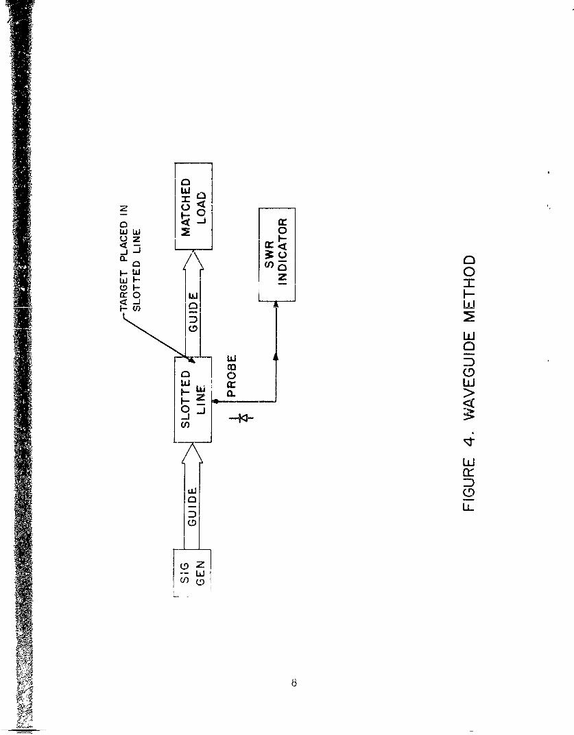
WAVEGUIDE METHD
This method is diagrammed in Figure 4. Readily available eqlipment isused to produce conclusive values of cross section for individual mosquitoes.
The mismatch of the dmny load must be minimized. In this experiment atX-band, the VSWR of the load was reduced to 1.015:1. This value Js low enoughto detect targets as small as 10-10 m2 . Targets cin now be introduced betweenthe slotted line and load, and the new SWR measured. All targets were orientedfor maximwm reflected power. Calibration is accomplished in a manner similarto that used in the doppler method, Steel balls are used as standard targets.An empirical plot of a- vs. VSWR could be drawn. However, since
where K is an experimentally detennined constant and P is the reflection co-effi, 'ent found from the measured SWR, a graph of o- vs f 2 would be more use-ful. ).is curve is plotted in Figure 5. The mu~tiplicative constant, K, isnecessary to account for power dersity which is a function of position withinthe waveguide.
The value of p2 for the i/A" diameter ball cannot be expected to followthe square law relation, since 1/44" is an appreciable fraction of the wave-glide height. The lower shaded area of Figure 5 indicates the range of crosssections measured for individual dead mosquitoes.
Trials with live mosquitoes were also quite successful, As expected, re-turns were greater than those from the humidified, dead mosquitoes. Figure 5shows thb range of live mosquito cross sections measured at X-band. Valuesfrom 10-0 to 5 x I0-8 were obtained.
Mosquito cross sections have also been measured at Ku-band using the wave-fuide method. At 16 GHz, an increase of approximately 10 dB (over 9.5 GHz re-turns) was expected. Note that actual returns were 20 dB greater. The extra10 dB was caused by the larger physical size of this sample of mosquitoes.
2

The Ku-band data are presented in .- igure 6. Plotted values represent the aver-age cross section of five trials.
Ku-band has a distinct advantage over X-band for mall cross section meas-urements. Reflections at Ku-band are stronger making possible the detectionof smaller targets at Ku-band than at lower frequencies. By the same reasoningfor a given size target, the Ku-band duiwy load does not need to be as wellmatc.ied to the waveguide as does the X-band load.
CONCLUSIONS
The doppler method of measuring small radar cross sections proved unreli-able. The waveguids method produced repeatable results with cross sections .assmall as 10-10 m2 .
Using the waveguide method, •he cross section of a single, live musquitohas been determined to be 5 x O1 m2 at X-band. Ku-4and measurements pro-duced a value of 10-6 m2 . For a given radar frequency, variations in crosssection of as much as 10 dB can be expected due to differing physical dimen-sions of the individual mosquitoes.
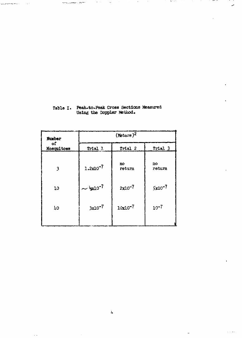
Table I. Peak-to-Peak Cross Sections MeasuredUsing the Doppler Method.
N um b e r _ _ _ _,- s )
Nosqitoesa Trial 1. Trial 2 Trial 3
no no3 .2xlO' retirn return
10 - ½clo07 2xlO"7 57
40 3x10⁻⁷ lOxlO-7 10-7
4
TARGET IS PROPELLEDBY COMPRESSED AiR
FLOW
RADARBEAM
BOXCA PZ STORAGE
[ DETECTOR L: SCOPE
FIGURE 1. DOFPLER TECHNIQUE FOR MEASURING SMALLCRO.S SECTIONS
C7
a:wCL
I-..>
00
N~
-000z
000
3 00 0
C1rj
04
(d -d S1-1 A) ndin 8o iii~ a c, xo E
6ML
2 S/DIV
FIGURE 3. BOXCAR DETECTOR OUTPUT VERSUS TIME
z H0
00
ww 0
0
-i Ll
w 5l
0-j -43
Lu
DU-9
-- LL
Jii

F-
00
LLi>
00
I-L
cc
00
(D 00
00 0~
(S813W NO03SSSOO U(]0
90

CDC
w>0
U7
aA
W 0
ON. z
wcc
10 00 - LL..0 to b 0
(S8±313) N01103~S ISSO?0 8V0V8
310


![[4008] – 301](https://img.pdfslide.us/doc/110x75/61bd08ba61276e740b0eadd4/4008-301.jpg)