Embed Size (px)
Citation preview
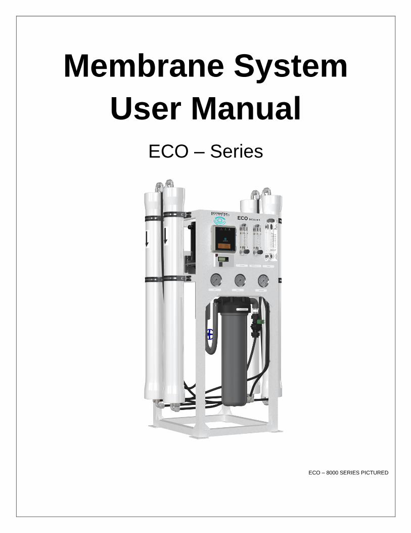
Membrane System
User Manual
ECO – Series
ECO – 8000 SERIES PICTURED
w

ECO – Series User Manual MKTF – 487–B 2 03/18
This page intentionally
left blank

ECO – Series User Manual MKTF – 487–B 3 03/18
TABLE OF CONTENTS
INTRODUCTION ............................................................................................................ 4
SAFETY .......................................................................................................................... 5
FEEDWATER AND OPERATION SPECIFICATIONS ..................................................... 6
REJECTION, RECOVERY AND FLOW RATES ............................................................. 7
SYSTEM REQUIREMENTS AND OPERATION GUIDELINES ....................................... 8
ELECTRICAL .................................................................................................................. 9
MEMBRANE ELEMENTS ............................................................................................. 10
SYSTEM IDENTIFICATION .......................................................................................... 11
MEMBRANE INSTALLATION, REMOVAL AND REPLACEMENT ................................ 13
SYSTEM PURGING ..................................................................................................... 16
INITIAL START–UP ...................................................................................................... 17
OPERATING DO’S AND DON’TS ................................................................................. 18
RO SHUT–DOWN PROCEDURE ................................................................................. 18
PRODUCT SPECIFICATIONS ...................................................................................... 19
SYSTEM OPERATING LIMITS ..................................................................................... 20
OPERATION AND MAINTENANCE .............................................................................. 21
PUMP THROTTLE VALVE ........................................................................................... 22
FLUSHING THE SYSTEM ............................................................................................ 23
PREPARING UNIT FOR STORAGE AND SHIPMENT ................................................. 24
TROUBLESHOOTING .................................................................................................. 25
OPERATING LOG ........................................................................................................ 27
TEMPERATURE CORRECTION FACTORS FOR MEMBRANE .................................. 28
SERVICE ASSISTANCE ............................................................................................... 29
SYSTEM DRAWINGS................................................................................................... 30
ELECTRICAL SCHEMATIC .......................................................................................... 32
SYSTEM WARRANTY .................................................................................................. 33

ECO – Series User Manual MKTF – 487–B 4 03/18
INTRODUCTION
Your ECO – Series Reverse Osmosis System is a durable piece of equipment which, with
proper care, will last for many years. This User Manual outlines installation, operation,
maintenance and troubleshooting details vital to the sustained performance of your
system.
If your system is altered at the site of operation, or if the feedwater conditions change,
please contact your local dealer or distributor to determine the proper recovery for your
application.
IN ORDER TO MAINTAIN THE MANUFACTURER’S WARRANTY, AN
OPERATING LOG MUST BE MAINTAINED AND COPIES WILL NEED TO BE
SENT TO YOUR LOCAL DEALER OR DISTRIBUTOR FOR REVIEW.
PRIOR TO OPERATING OR SERVICING THE REVERSE OSMOSIS SYSTEM,
THIS USER MANUAL MUST BE READ AND FULLY UNDERSTOOD. KEEP THIS
AND OTHER ASSOCIATED INFORMATION FOR FUTURE REFERENCE AND
FOR NEW OPERATORS OR QUALIFIED PERSONNEL NEAR THE SYSTEM.

ECO – Series User Manual MKTF – 487–B 5 03/18
SAFETY
The Safety section of this User Manual outlines the various safety headings used throughout
this manual’s text and are enhanced and defined below:
CAUTION: INDICATES STATEMENTS THAT ARE USED TO IDENTIFY
CONDITIONS OR PRACTICES THAT COULD RESULT IN EQUIPMENT OR
OTHER PROPERTY DAMAGE.
WARNING: INDICATES STATEMENTS THAT ARE USED TO IDENTIFY
CONDITIONS OR PRACTICES THAT COULD RESULT IN INJURY OR LOSS
OF LIFE. FAILURE TO FOLLOW WARNINGS COULD RESULT IN SERIOUS
INJURY OR EVEN DEATH.
DO NOT, UNDER ANY CIRCUMSTANCES, REMOVE ANY CAUTION,
WARNING OR OTHER DESCRIPTIVE LABELS FROM THE SYSTEM.
PLEASE READ THE ENTIRE MANUAL BEFORE PROCEEDING WITH
THE INSTALLATION AND START–UP. FAILURE TO FOLLOW
INSTRUCTIONS OR OPERATING PARAMETERS MAY LEAD TO THE
PRODUCT’S FAILURE, WHICH CAN CAUSE PROPERTY DAMAGE
AND/OR PERSONAL INJURY.
• DO NOT USE WHERE THE WATER IS MICROBIOLOGICALLY UNSAFE OR OF
UNKNOWN QUALITY WITHOUT ADEQUATE DISINFECTION BEFORE OR AFTER
THE SYSTEM.
• PRE–TREATMENT MUST BE SUFFICIENT TO ELIMINATE CHEMICALS,
ORGANICS OR INORGANICS THAT COULD ATTACK THE MEMBRANE MATERIAL.
• ALWAYS TURN OFF THE UNIT, SHUT OFF THE FEEDWATER AND DISCONNECT
THE ELECTRICAL POWER BEFORE WORKING ON THE UNIT.
• NEVER ALLOW THE PUMP TO RUN DRY.
• NEVER START THE PUMP WITH THE CONCENTRATE OR GLOBE /THROTTLE
VALVE CLOSED.
• NEVER ALLOW THE UNIT TO FREEZE OR OPERATE WITH A FEEDWATER
TEMPERATURE ABOVE 85°F.

ECO – Series User Manual MKTF – 487–B 6 03/18
FEEDWATER AND OPERATION SPECIFICATIONS Nothing has a greater effect on a reverse osmosis system than the feedwater quality.
IT IS VERY IMPORTANT TO MEET THE MINIMUM FEEDWATER
REQUIREMENTS. FAILURE TO DO SO WILL CAUSE THE MEMBRANES
TO FOUL AND VOID THE MANUFACTURER’S WARRANTY.
OPERATING LIMITS*
Operating Parameters:
Feed Temperature 40 – 85°F
System Inlet Pressure 45 – 85 psi
Maximum Operating Pressure (at 77°F) 200 psi
Feedwater Requirements:
Maximum SDI Rating < 3
Maximum Turbidity 1 NTU
Maximum Free Chlorine and/or Chloramines 0 PPM
PH (continuous) 2 – 11
PH (cleaning for 30 minutes) 1 – 13
*If any of the feedwater parameters are not within the limits given, consult your local dealer or distributor for assistance.
HIGHER TDS AND/OR LOWER TEMPERATURES WILL REDUCE THE
SYSTEM’S PRODUCTION.

ECO – Series User Manual MKTF – 487–B 7 03/18
REJECTION, RECOVERY AND FLOW RATES
ECO – Series Reverse Osmosis Systems are designed to produce permeate water at
the capacities indicated by the suffix in the system’s name under the conditions listed
above. For example, the ECO – 2000 system produces 2,000 gallons per day of
permeate water at the listed operating test conditions.
The amount of total dissolved solids (TDS) rejected by the membrane is expressed
as a percentage. For example, a 98.5% rejection rate means that 98.5% of total
dissolved solids do not pass through the membrane. To calculate the percentage of
rejection, use the following formula:
% Rejection = [(Feed TDS – Product TDS) / Feed TDS] x 100
Example:
98.5% = [(550 – 8.25) / 550] x 100
ALL TDS FIGURES MUST BE EXPRESSED IN THE SAME UNITS, TYPICALLY
PARTS PER MILLION (PPM) OR MILLIGRAMS PER LITER (MG/L).
ECO – Series Reverse Osmosis Systems are designed to reject up to 98.5% NaCl,
unless computer projections have been provided or stated otherwise.
The amount of permeate water recovered for use is expressed as a percentage. To
calculate the percentage of recovery, use the following formula:
% Recovery = (Product Water Flow Rate / Feed Water Flow Rate) x 100
Example:
50% = (1.02 / 2.04) x 100
ALL FLOW RATES MUST BE EXPRESSED IN THE SAME UNITS, TYPICALLY
GALLONS PER MINUTE (GPM).

ECO – Series User Manual MKTF – 487–B 8 03/18
SYSTEM REQUIREMENTS AND OPERATION GUIDELINES
PLUMBING
The membranes and high pressure pumps used on ECO – Series systems require a
continuous flow of water with a minimum feed pressure of 45 psi, not to exceed 85 psi.
FEEDWATER CONNECTION
1. Locate the 3/4” FNPT solenoid valve feed water inlet. 2. Attach the inlet piping to the 3/4” FNPT solenoid valve feedwater inlet. 3. Be certain that all of the components of the feedwater are soluble at the
concentrations attained in the system. FEED LINE MUST BE A MINIMUM OF 3/4” INCH.
PERMEATE (PRODUCT WATER) CONNECTION
Locate the 1/2” QC connector after the check valve on the outlet of the flow meter
labeled “permeate”, and attach to storage tank. Ensure that the permeate water can
flow freely with no backpressure. Backpressure can cause irreversible damage to the
membrane elements. The permeate line can be run to the holding tank with PVC fittings
or other FDA approved materials. This is so the material being used does not dissolve
into the permeate water.
THE PH OF THE REVERSE OSMOSIS PERMEATE WATER WILL TYPICALLY BE 1
OR 2 PH UNITS LOWER THAN THE FEEDWATER PH. A LOW PH CAN BE VERY
AGGRESSIVE TO SOME PLUMBING MATERIALS SUCH AS COPPER PIPING.
CONCENTRATE (WASTE WATER) CONNECTION
Locate the 1/2” QC outlet on the flow meter labeled “concentrate” and attach to a drain.
Run the concentrate line to an open drain in a free and unrestricted manner (no
backpressure).
ANY RESTRICTIONS OR BLOCKAGE IN THE DRAIN LINE CAN CAUSE
BACKPRESSURE, WHICH WILL INCREASE THE SYSTEM’S
OPERATING PRESSURE. THIS CAN RESULT IN DAMAGE TO THE
SYSTEM’S MEMBRANES AND COMPONENTS.

ECO – Series User Manual MKTF – 487–B 9 03/18
ELECTRICAL
The motor used on the ECO – Series systems are pump and motor combinations. The motor is available
in 110/220 VAC 60 Hertz 1 Phase. Each ECO – Series system is equipped with an eight–foot electrical cord. The 110V systems include a three–pronged electrical plug. Ensure that the electrical circuit supplying the system is compatible with the requirements of the specific
ECO – Series model you are installing.
IT’S RECOMMENDED THAT A LICENSED ELECTRICIAN WIRE YOUR SYSTEM IN ACCORDANCE WITH LOCAL AND NATIONAL ELECTRICAL CODES (NEC).
TO REDUCE THE RISK OF ELECTRICAL SHOCK, THE INCOMING POWER
SUPPLY MUST INCLUDE A PROTECTIVE EARTH GROUND.
ECO – Series systems are typically controlled with a liquid level switch in a storage tank. The liquid
level switch turns the system on when the water level in the tank drops, and off when the tank is full.
Liquid level switches can be obtained by your local dealer or distributor. If a liquid level switch is to be
used, install it at this time.
PRE–FILTRATION
ECO – Series systems are supplied with a 5–micron sediment filter. Change the cartridge once a
month or when a 10 – 15 psi differential exists between the two pre–filter gauges.
THE SYSTEM MUST BE OPERATED ON FILTERED WATER ONLY.
PUMP
The pump type used on the ECO – Series systems is multi–stage centrifugal stainless steel. If any
damage occurs to your system’s pump, a re–build kit may be available. Contact your local dealer or
distributor and inform them of your system and pump model.
MOUNTING
The free standing system should be bolted down or securely fastened in compliance with local
regulation standards. The system comes standard with a rubber bumper kit. Casters and levelers are
available but optional.

ECO – Series User Manual MKTF – 487–B 10 03/18
MEMBRANE ELEMENTS
The ECO – Series Reverse Osmosis Systems are equipped with Thin Film Composite (TFC) HF5 – Ultra Low
Energy Membranes unless otherwise specified. General membrane element performance characteristics are
listed below.
HF5 – Ultra Low Energy Membranes
▪ Membrane Type: Polyamide Thin – Film Composite ▪ pH Range, Short Term Cleaning (30 Min.): 1 – 13
▪ Maximum Operating Temperature: 113°F (45°C) ▪ Maximum Feed Silt Density Index (SDI): 5
▪ Maximum Operating Pressure: 400 psi (27.58 bar) ▪ Chlorine Tolerance: 0 ppm
▪ pH Range, Continuous Operation*: 2 – 11 ▪ Maximum Feed Flow Rate (gpm): 2.5” = 6; 4.0” = 16
*Maximum temperature for continuous operations above pH10 is 95°F (35°C).
Product Specifications
Part Number Description Applied Pressure
psi / bar Permeate Flow Rate
gpd / m3/d Nominal Salt Rejection
(%)
208125 HF5 – 2514 80 / 5.2 225 / 0.85 98.5%
208083 HF5 – 2521 80 / 5.2 400 / 1.51 98.5%
208084 HF5 – 2540 80 / 5.2 850 / 3.22 98.5%
200392 HF5 – 4014 80 / 5.2 600 / 2.27 98.5%
200393 HF5 – 4021 80 / 5.2 1000 / 3.79 98.5%
200394 HF5 – 4040 80 / 5.2 2500 / 9.46 98.5%
Warranty Evaluation Test Conditions: Permeate flow and salt rejection based on the following test conditions – 550 ppm, filtered and dechlorinated municipal tap water, 77°F / 25°C, 15% recovery and the specified operating pressure. Minimum salt rejection is 96%. Permeate flows for warranty evaluation may vary +/–20%. Maximum pressure drops at 13 psi / 0.9 bar.
Dimensions inch / mm
Description A B C D
HF5 – 2514 14 / 355.6 1.1 / 27.94 0.75 / 19.05 2.40 / 60.96
HF5 – 2521 21 / 533.4 1.1 / 27.94 0.75 / 19.05 2.40 / 60.96
HF5 – 2540 40 / 1016.0 1.1 / 27.94 0.75 / 19.05 2.40 / 60.96
HF5 – 4014 14 / 355.6 1.1 / 27.94 0.75 / 19.05 3.95 / 100.3
HF5 – 4021 21 / 533.4 1.1 / 27.94 0.75 / 19.05 3.95 / 100.3
HF5 – 4040 40 / 1016.0 1.1 / 27.94 0.75 / 19.05 3.95 / 100.3
Proper start–up of reverse osmosis water treatment systems is essential to prepare the membranes for operating service and to prevent membrane damage due to overfeeding or hydraulic shock. Before initiating system start–up procedures, membrane pretreatment, loading of the membrane elements, instrument calibration and other system checks should be completed.
Avoid any abrupt pressure or cross–flow variations on the spiral elements during start–up, shutdown, cleaning or other sequences to prevent possible membrane damage. During start–up, a gradual change from a standstill to operating state is recommended as follows:
▪ Feed pressure should be increased gradually over a 30 – 60 second time frame. ▪ Cross–flow velocity at set operating point should be achieved gradually over 15 – 20 seconds. ▪ Permeate obtained from first hour of operation should be discarded. ▪ Maximum pressure drops across an entire pressure vessel (housing) is 30 psi / 2.1 bar. ▪ Avoid static permeate–side backpressure at all times.
Under certain conditions, the presence of free chlorine, chloramines and other oxidizing agents will cause premature membrane failure. Since oxidation damage is not covered under warranty, the manufacturer recommends removing all oxidizing agents by pretreatment prior to membrane exposure. Please contact the manufacturer or your supplier for more information.
Do not use this initial permeate for drinking water or food preparation. Keep elements moist at all times after initial wetting. To prevent biological growth during prolonged system shutdowns, it is recommended that membrane elements be immersed in a preservative solution. Rinse out the preservative before use. For membrane warranty details, please contact the manufacturer or your supplier for more information.
If operating limits and guidelines given in this product specification sheet are not strictly followed, the warranty will be null and void. The customer is fully responsible for the effects of incompatible chemicals and lubricants on elements. Use of any such chemicals or lubricants will void the warranty. These membranes may be subject to drinking water application restrictions in some countries: please check the application status before use and sale. The use of this product in and of itself does not necessarily guarantee the removal of cysts and pathogens from water. Effective cyst and pathogen reduction is dependent on the complete system design and on the operation and maintenance of the system.
No freedom from infringement of any patent owned by the manufacturer or others is to be inferred. Because use conditions and applicable laws may differ from one location to another and may change with time, customer is responsible for determining whether products and the information in this document are appropriate for customer’s use and for ensuring that customer’s workplace and disposal practices are in compliance with applicable laws and other governmental enactments. The claims made may not have been approved for use in all countries. The manufacturer assumes no obligation or liability for the information in this document. NO WARRANTIES ARE GIVEN; ALL IMPLIED WARRANTIES OF MERCHANTABILITY OR FITNESS FOR A PARTICULAR PURPOSE ARE EXPRESSLY EXCLUDED.

ECO – Series User Manual MKTF – 487–B 11 03/18
SYSTEM IDENTIFICATION
Figure 1

ECO – Series User Manual MKTF – 487–B 12 03/18
SYSTEM IDENTIFICATION
ITEM NO.
DESCRIPTION PART
NUMBER MODELS
1 CARTRIDGE, SEDIMENT, POLYPRO, 4.5" X 20", 5 MIC 200640 2000-8000
2 CONTROLLER, COMPUTER, C-26, 110V/220V, 1PH, 50/60HZ 210355 2000-8000
3 GAUGE, BKM, GLY FILL, 0-100 PSI/BAR, 2.5" DIA, 1/4" MNPT, AXEON 204165 2000-8000
4 GAUGE,PM,GLY FILL,0-300 PSI/BAR,2.5 DIA,SS,1/4"MNPT,AXEON 203511 2000-8000
5 HOUSING, FILTER, BLK/GRY, 4.5" X 20", SGL O-RING, NPR, 3/4" FNPT, AXEON 207289 2000-8000
6 HOUSING, MEMBRANE, FRP-300E, 4040, 1/2" P X 3/4" C FNPT, AXEON 208419 2000-8000
7 MEMBRANE, HF5, 4040, DRY, AXEON 200394 2000-8000
8 METER, FLOW, PM, 0.2-2 GPM, SS VALVE, 1/2" MNPT X 1/2" MNPT, AXEON 205103 2000
9 METER, FLOW, PM, 1-5 GPM, SS VALVE, 1/2" MNPT X 1/2" MNPT, AXEON 205104 2000-8000
10 METER, TDS, INLINE, FRONT PANEL 203385 2000-8000
11 METER, FLOW, PM, 0.2-2 GPM, 1/2" MNPT x 1/2" MNPT, ABS FTG, AXEON 200897 2000
12 METER,FLOW,PM,1-5 GPM,1/2" MNPT X 1/2" MNPT 200898 4000, 6000
13 METER, FLOW, PM, 1-10 GPM, 1" MNPT x 1" MNPT, AXEON 200899 8000
14 PUMP, BOOSTER, 1/2-3/4HP, 115/230V, 1PH, 7FBT05S4, FRANKLIN 207129 2000, 4000
15 PUMP, BOOSTER, 1 - 1 1/2HP, 115/230V, 1PH, 7FBT1S4, FRANKLIN 207130 6000, 8000
16 SWITCH, PRESSURE, LOW, N/O 15-30, 1/4 FNPT 200906 2000-8000
17 VALVE, CHECK, PVC, 1/2" FNPT X 1/2" FNPT 200965 2000-8000
18 VALVE, GLOBE, SS, 3/4" FNPT 200994 2000-8000
19 VALVE, SOLENOID, 2-WAY, COMPOSITE, 220V, 3/4'' FNPT, ASCO 207088 6000, 8000
20 VALVE, SOLENOID, 2-WAY, COMPOSITE, 120V, 3/4"FNPT, ASCO 207472 2000, 4000

ECO – Series User Manual MKTF – 487–B 13 03/18
MEMBRANE INSTALLATION, REMOVAL AND REPLACEMENT
Installation and replacing membranes in the pressure vessels is an easy process if you
have the proper information and tools at hand. Please refer to the following instructions
when removing and replacing membrane elements:
ALL PRESSURE GAUGES MUST READ ZERO BEFORE PROCEEDING.
BEFORE ATTEMPTING, DISCONNECT THE POWER FROM THE
SYSTEM AND BLEED ALL WATER PRESSURE FROM THE SYSTEM.
1. Remove the end plugs from the top of the pressure vessels. This is done by removing the two locking crescents using a #5 Allen wrench; the end plugs should then freely slide out of the pressure vessel.
2. Remove the replacement membrane element(s) from the shipping box; the membrane(s) should be contained within a plastic bag.
WEAR GLOVES FOR THE FOLLOWING STEPS IN ORDER NOT TO
CONTAMINATE THE MEMBRANE.
3. Cut the bag open as close as possible to the seal at one end of the bag, so the bag may be re–used if necessary.
4. Make sure that all parts are clean and free from dirt. Examine the brine seal, and permeate tube for nicks or cuts. Replace the o–rings or brine seal on the end plug if damaged.
5. Flow directions should be observed for installation of each element into their respective pressure vessels.

ECO – Series User Manual MKTF – 487–B 14 03/18
REPLACING THE MEMBRANE ELEMENT:
THE BRINE SEAL MUST BE IN THE CORRECT POSITION FOR EACH
MEMBRANE ELEMENT HOUSINGS. THE BRINE SEAL IS A RUBBER SEAL
THAT PROTRUDES ON ONE SIDE OF THE MEMBRANE AND IS ALWAYS ON
THE FEED SIDE OF THE MEMBRANE ELEMENT. FOR ECO – SERIES
REVERSE OSMOSIS SYSTEMS THE BRINE SEAL SHOULD BE ON THE TOP
SIDE OF THE MEMBRANE HOUSINGS.
1. Remove one membrane element at a time from the pressure vessels, from the top of each housing. Long nose pliers may be necessary to pull the old membrane element out of the membrane element housing.
2. Lubricate the brine seal and o–rings with a non–petroleum based lubricant, such as Dow Corning® 111. Do not use a petroleum–based lubricant.
3. Install membranes with brine seal location depicted in. (Figure 2, Page 15)
4. With a smooth and constant motion, push the membrane element into the housing so the brine seal enters the housing without coming out of the brine seal groove.
5. Re–install the end plugs by gently twisting the end cap, while pushing it onto the housing. Ensure that you do not pinch or fatigue any o–rings while re–installing the end plug. Push the end plug on until the outer diameter of the plug is flush with the outer diameter of the pressure vessel.
6. Insert the two locking crescents until they are fully seated. Subsequently fasten using a #5 Allen wrench.
7. Reconnect any fittings that may have been disconnected when the membrane pressure vessels were disassembled.
8. To start–up the system, please refer to the Initial Start–Up section of this User Manual.
THE MEMBRANES MUST BE FLUSHED FOR AT LEAST 30 MINUTES TO
REMOVE THE PRESERVATIVE FROM THE MEMBRANE. DISCARD ALL OF THE
PERMEATE, WHICH IS PRODUCED DURING THE FLUSH PERIOD.
ECO – Series User Manual MKTF – 487–B 15 03/18
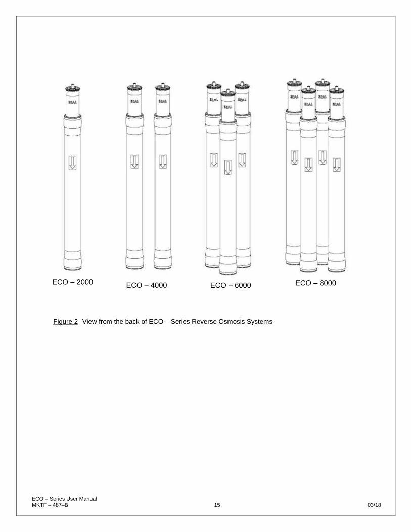
Figure 2 View from the back of ECO – Series Reverse Osmosis Systems
ECO – 2000
ECO – 4000 ECO – 6000 ECO – 8000

ECO – Series User Manual MKTF – 487–B 16 03/18
SYSTEM PURGING
MAKE SURE THE SYSTEM POWER SWITCH IS IN THE OFF POSITION
BEFORE BEGINNING THIS PROCEDURE.
1. Redirect permeate water to the drain for this procedure.
2. Fully open the concentrate valve by turning it counter–clockwise.
(#9, Figure 1, Page 11)
3. Fully close the concentrate recycle valve by turning it clockwise.
(#8,9, Figure 1, Page 11)
4. Fully open the throttle valve by turning it counter–clockwise.
(#18, Figure 1, Page 11; and Figure 4, Page 22)
5. Activate the manual feed flush feature by pressing and holding the power button on the C26
Controller for 5 seconds. The system will flush for 60 seconds. To end the flush before the 60
second cycle is complete, press the power button once.
6. Let the system purge until no visible bubbles appear from concentrate flow meter. It may be
necessary to flush the system more than one cycle.
Figure 3

ECO – Series User Manual MKTF – 487–B 17 03/18
INITIAL START–UP
Carefully inspect your system before initial start–up. Check that all plumbing and
electrical connections are not loose or have not come undone during shipment.
Keep the permeate water line to drain for this procedure.
1. Fully open the concentrate valve by turning it counter–clockwise.
(#9, Figure 1, Page 11)
2. Fully close the concentrate recycle valve by turning it clockwise.
(#8,9, Figure 1, Page 11)
3. Fully close the throttle valve clockwise. Once fully closed, open half a
turn counter–clockwise.
(#18, Figure 1, Page 11; and Figure 4, Page 22)
4. Turn the RO system on and adjust the concentrate (waste) valve,
recycle valve and the throttle valve to the designed flow and pressure.
5. Inspect the system for leaks.
6. Allow the system to run 30 minutes to flush the preservative solution
from the system.
7. After 30 minutes, shut down the system.
8. Re–direct the permeate water back to the tank and then turn the
system back on.
9. Record the readings daily for a week; after one week record the
readings once a week.

ECO – Series User Manual MKTF – 487–B 18 03/18
OPERATING DO'S AND DON'TS
DO:
• Change the cartridge filters regularly.
• Monitor the system and keep a daily log.
• Run the system as much as possible on a continuous basis.
• Adjust the system recovery to the recommended value.
• Always feed the pump with filtered water.
DON’T
• Permit chlorine to enter or be present in the feedwater.
• Shut down the system for extended periods.
• Close the throttle valve completely.
• Operate the system with insufficient feed flow.
• Operate the pump dry.
RO SHUT–DOWN PROCEDURE
1. Purge system. See Purging and Initial Start–up instructions.
2. Turn off feed supply water from system.
3. Set the system power switch to the off position. Unplug the system power cord
from wall.
4. When the unit is ready to restart please follow the initial start–up procedures. The
permeate line should be diverted to drain for 30 minutes.
If the RO unit is to be shut down for an extended period of time, a membrane preservative
should be used to preserve the membranes. See Preparing Unit for Storage or Shipment
instructions.

ECO – Series User Manual MKTF – 487–B 19 03/18
PRODUCT SPECIFICATIONS
MODELS ECO – 2000 ECO – 4000 ECO – 6000 ECO – 8000
Design
Configuration Single Pass Single Pass Single Pass Single Pass
Feedwater Source† TDS < 2000 TDS < 2000 TDS < 2000 TDS < 2000
System Recovery with Recycle
Up to 60% Up to 75% Up to 75% Up to 75%
Rejection and Flow Rates†††
Nominal Salt Rejection 98.50% 98.50% 98.50% 98.50%
Permeate Flow Rate 1.39 gpm 2.78 gpm 4.17 gpm 5.56 gpm
Concentrate Flow Rate (minimum)
3.00 gpm 3.00 gpm 3.00 gpm 3.00 gpm
Concentrate Recycle Flow Rate
Up to 2.00 gpm Up to 5.00 gpm Up to 5.00 gpm Up to 5.00 gpm
Connections
Feed Connection 3/4” FNPT 3/4” FNPT 3/4” FNPT 3/4” FNPT
Permeate Connection 1/2” QC 1/2” QC 1/2” QC 1/2” QC
Concentrate Connection 1/2” QC 1/2” QC 1/2” QC 1/2” QC
Membranes
Membranes Per Vessel 1 1 1 1
Membrane Quantity 1 2 3 4
Membrane Size 4040 4040 4040 4040
Vessels
Vessel Array 1 1:1 1:1:1 1:1:1:1
Vessel Quantity 1 2 3 4
Pump
Pump Type Multi–stage Multi–stage Multi–stage Multi–stage
Motor HP 1/2 – 3/4 1/2 – 3/4 1 – 1 1/2 1 – 1 1/2
RPM at 60HZ 3450 3450 3450 3450
System Electrical
Controller C – 26 C – 26 C – 26 C – 26
High Voltage Service + Amp Draw
110V 1PH 60 HZ 13.4A**
110V 1PH 60 HZ 13.4A**
110V 1PH 60 HZ 10.94A**
220V 1PH 60 HZ 10.94A**
System Dimensions
Approximate Dimensions* (L x W x H)
25” x 25” x 56” 25.5” x 30” x 56” 25.5” x 30” x 56” 25.5” x 30” x 56”
Approximate Weight 130 lbs. 140 lbs. 155 lbs. 180 lbs.
Warranty Evaluation Test Conditions: Permeate flow rates and salt rejection based on the following test conditions – 550 ppm, filtered and dechlorinated municipal tap water, 77°F / 25°C, 15% recovery, 7.0 pH and the specified operating pressure for membrane element type. Data taken after 60 minutes of operation. * Does not include operating space requirements. ** Varies with motor manufacturer.
ECO – Series User Manual MKTF – 487–B 20 03/18
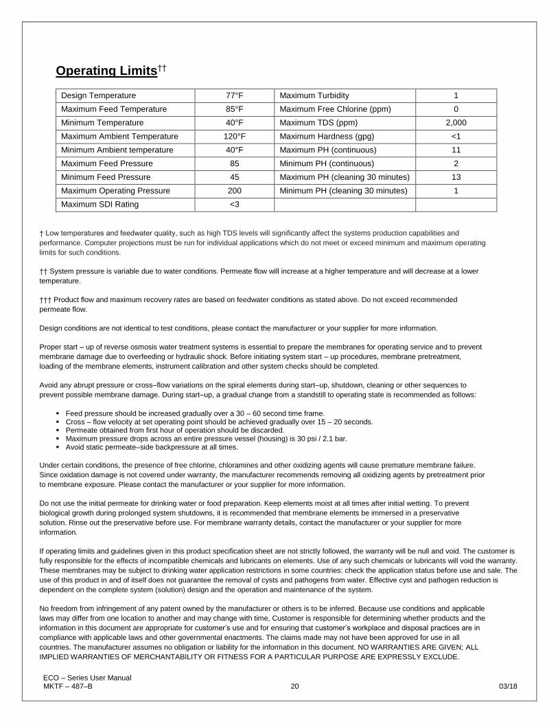
Operating Limits††
Design Temperature 77°F Maximum Turbidity 1
Maximum Feed Temperature 85°F Maximum Free Chlorine (ppm) 0
Minimum Temperature 40°F Maximum TDS (ppm) 2,000
Maximum Ambient Temperature 120°F Maximum Hardness (gpg) <1
Minimum Ambient temperature 40°F Maximum PH (continuous) 11
Maximum Feed Pressure 85 Minimum PH (continuous) 2
Minimum Feed Pressure 45 Maximum PH (cleaning 30 minutes) 13
Maximum Operating Pressure 200 Minimum PH (cleaning 30 minutes) 1
Maximum SDI Rating <3
† Low temperatures and feedwater quality, such as high TDS levels will significantly affect the systems production capabilities and
performance. Computer projections must be run for individual applications which do not meet or exceed minimum and maximum operating
limits for such conditions.
†† System pressure is variable due to water conditions. Permeate flow will increase at a higher temperature and will decrease at a lower
temperature.
††† Product flow and maximum recovery rates are based on feedwater conditions as stated above. Do not exceed recommended
permeate flow.
Design conditions are not identical to test conditions, please contact the manufacturer or your supplier for more information.
Proper start – up of reverse osmosis water treatment systems is essential to prepare the membranes for operating service and to prevent
membrane damage due to overfeeding or hydraulic shock. Before initiating system start – up procedures, membrane pretreatment,
loading of the membrane elements, instrument calibration and other system checks should be completed.
Avoid any abrupt pressure or cross–flow variations on the spiral elements during start–up, shutdown, cleaning or other sequences to
prevent possible membrane damage. During start–up, a gradual change from a standstill to operating state is recommended as follows:
▪ Feed pressure should be increased gradually over a 30 – 60 second time frame. ▪ Cross – flow velocity at set operating point should be achieved gradually over 15 – 20 seconds. ▪ Permeate obtained from first hour of operation should be discarded. ▪ Maximum pressure drops across an entire pressure vessel (housing) is 30 psi / 2.1 bar. ▪ Avoid static permeate–side backpressure at all times.
Under certain conditions, the presence of free chlorine, chloramines and other oxidizing agents will cause premature membrane failure.
Since oxidation damage is not covered under warranty, the manufacturer recommends removing all oxidizing agents by pretreatment prior
to membrane exposure. Please contact the manufacturer or your supplier for more information.
Do not use the initial permeate for drinking water or food preparation. Keep elements moist at all times after initial wetting. To prevent
biological growth during prolonged system shutdowns, it is recommended that membrane elements be immersed in a preservative
solution. Rinse out the preservative before use. For membrane warranty details, contact the manufacturer or your supplier for more
information.
If operating limits and guidelines given in this product specification sheet are not strictly followed, the warranty will be null and void. The customer is
fully responsible for the effects of incompatible chemicals and lubricants on elements. Use of any such chemicals or lubricants will void the warranty.
These membranes may be subject to drinking water application restrictions in some countries: check the application status before use and sale. The
use of this product in and of itself does not guarantee the removal of cysts and pathogens from water. Effective cyst and pathogen reduction is
dependent on the complete system (solution) design and the operation and maintenance of the system.
No freedom from infringement of any patent owned by the manufacturer or others is to be inferred. Because use conditions and applicable
laws may differ from one location to another and may change with time, Customer is responsible for determining whether products and the
information in this document are appropriate for customer’s use and for ensuring that customer’s workplace and disposal practices are in
compliance with applicable laws and other governmental enactments. The claims made may not have been approved for use in all
countries. The manufacturer assumes no obligation or liability for the information in this document. NO WARRANTIES ARE GIVEN; ALL
IMPLIED WARRANTIES OF MERCHANTABILITY OR FITNESS FOR A PARTICULAR PURPOSE ARE EXPRESSLY EXCLUDE.

ECO – Series User Manual MKTF – 487–B 21 03/18
OPERATION AND MAINTENANCE
The reverse osmosis process causes the concentration of impurities. The impurities
may precipitate (come out of solution) when their concentration reaches saturation
levels.
PRECIPITATION CAN SCALE OR FOUL MEMBRANES AND MUST BE
PREVENTED.
Check your feedwater chemistry and pre–treat the water and/or reduce the system’s
recovery as required. If necessary, consult with your local dealer or distributor.
PRE–FILTER PRESSURE GAUGES
These gauges measure the feedwater pressure when it enters and exits the pre–
filters. A pressure differential of 10 – 15 psi or more on the two pressure gauges
indicates that the pre–filters require servicing. For example, if the inlet pressure is 45
psi, the filter should be changed when the outlet pressure is 30 psi or below.
PERMEATE (PRODUCT) FLOW METER, CONCENTRATE (WASTE) FLOW
METER AND RECYCLE FLOW METER.
These flow meters indicate the flow rates of the permeate, concentrate and recycle
water. The measurements, when added together, also indicate the feedwater flow
rate or (total flow rate).
EXCESSIVE RECYCLING MAY CAUSE PREMATURE FOULING OR SCALING OF THE MEMBRANE ELEMENTS.
LOW PRESSURE SWITCH The low pressure switch shuts off the system when the feedwater pressure drops
below 15 psi, preventing damage to the pump. The system restarts automatically
when there is a constant pressure of 35 psi or more.
IF YOU NOTICE THE PRESSURE FLUCTUATING, AND THE SYSTEM
CYCLING OFF AND ON, TURN THE SYSTEM OFF AND ENSURE THAT
PROPER FEED FLOW AND PRESSURE ARE AVAILABLE TO THE
SYSTEM.

ECO – Series User Manual MKTF – 487–B 22 03/18
PUMP THROTTLE VALVE
The Pump Throttle Valve is installed as a standard feature on the ECO – Series
Reverse Osmosis Systems. It provides an adjustment for pump pressure. As the
feedwater temperature decreases, and/or the feedwater TDS increases, the system
will require a higher operating pressure to produce the specified permeate flow.
ADJUSTING THE THROTTLE VALVE
To decrease the pressure, turn the handle clockwise. To increase the pressure, turn
the handle counter clockwise. (Figure 4)
Figure 4

ECO – Series User Manual MKTF – 487–B 23 03/18
FLUSHING THE SYSTEM
The system should be flushed weekly to remove sediment from the surface of the
membranes. To manually flush the system, follow these steps:
1. The system must be operating during the flush procedure.
2. Fully open the concentrate valve by turning it counter–clockwise. (#9, Figure 1, Page 11)
3. Allow the system to run for 10 to 20 minutes.
4. After 10 to 20 minutes, close the concentrate valve to its previous setting. Ensure the proper concentrate flow rate is going to the drain.
5. The system is now ready to operate.

ECO – Series User Manual MKTF – 487–B 24 03/18
PREPARING UNIT FOR STORAGE OR SHIPMENT
PRIOR TO SHIPPING OR STORING YOUR SYSTEM, THE SYSTEM
SHOULD BE CLEANED WITH AN APPROPRIATE CLEANER, FLUSHED
WITH WATER AND PROTECTED FROM BIOLOGICAL ATTACK WITH AN
APPROPRIATE SOLUTION FOR MEMBRANE ELEMENTS. THE
MEMBRANE HOUSING(S) AND PLUMBING LINES OF THE SYSTEM
MUST BE COMPLETELY DRAINED. ANY WATER REMAINING IN THE
PLUMBING OF A SYSTEM MAY FREEZE, CAUSING SERIOUS DAMAGE.
Preparing system for storage:
1. Completely immerse the elements in the membrane housings using 2% M–100 solution*, venting the air outside of the pressure vessels. Use the overflow technique: circulate the M–100 solution in such a way that the remaining air in the system is minimized after the recirculation is completed. After the pressure vessel is filled, the M–100 solution should be allowed to overflow through an opening located higher than the upper end of the highest pressure vessel being filled. *For cold weather/winter storage add 20% by weight Polyglycol to the 2% M –
100 solution. Add Polyglycol AFTER the 2% M–100 solution has been mixed. 2. Separate the preservation solution from the air outside by closing all valves. Any
contact with oxygen will oxidize the M–100 solution.
3. Check the pH once a week. When the pH becomes 3 or lower, change the
preservation solution.
4. Repeat this process at least once a month.
During the shut–down period, the plant must be kept frost–free, or the ambient
temperature must not exceed 120°F (48.8°C) ambient.
Preparing unit for shipment:
1. Disconnect the inlet, concentrate, pre–filter, and permeate plumbing.
2. Drain all water from the pre–filter cartridge housings by unscrewing the
housings, removing the pre–filter cartridges, and drain the water from the
housings.
3. Disconnect the tubing from the connectors on the permeate and concentrate
inlets and outlets.
4. Fully open the concentrate valve.
5. Drain the flow meters.
Allow the system to drain for a minimum of eight hours or until the opened ports quit
dripping.
AFTER DRAINING IS COMPLETE, RECONNECT ALL OF THE
PLUMBING.

ECO – Series User Manual MKTF – 487–B 25 03/18
TROUBLESHOOTING
SYMPTOMS POSSIBLE CAUSES CORRECTIVE ACTION
Low Inlet Pressure
Low supply pressure Increase inlet pressure
Cartridge filters plugged Change filters
Solenoid valve malfunction Replace solenoid valve and/or coil
Leaks Fix any visible leaks
Low Permeate Flow
Low inlet flow Adjust concentrate valve
Cold feedwater See temperature correction sheet
Low operating pressure See low inlet pressure
Defective membrane brine seal Inspect and/or replace brine seal
Fouled or scaled membrane Clean membranes
High Permeate Flow
Damaged product tube o–rings Inspect and/or replace
Damaged or oxidized membrane Replace membrane
Exceeding maximum feedwater temperature See temperature correction sheet
Poor Permeate Quality
Low operating pressure See low inlet pressure
Damage product tube o–rings Inspect and/or replace
Damaged or oxidized membrane Replace membrane
Membrane Fouling
Metal oxide fouling Improve pretreatment to remove metals. Clean with acid cleaners
Colloidal fouling Optimize pretreatment for colloid removal. Clean with high pH anionic cleaners
Scaling (CaSO4, CaSO3, BaSO4, SiO2) Increase acid addition and antiscalant dosage for CaVO3 and CaCO4. Reduce recovery. Clean with acid cleaners
Biological fouling
Shock dosage of sodium bi–sulfate. Continuous feed of sodium bi–sulfate at reduced pH. Chlorination and de–chlorination. Replace cartridge filters
Organic fouling Activated carbon or another pretreatment. Clean with high pH cleaner
Abrasion of membrane by crystalline material
Improve pretreatment. Check all filters for media leakage

ECO – Series User Manual MKTF – 487–B 26 03/18
ABNORMAL PERMEATE FLOW
Permeate flow should be within 20% of the rated production, after correcting the
feedwater temperatures above or below 77°F. Check the permeate flow meter to
determine the permeate flow rate.
TO DETERMINE THE TEMPERATURE CORRECTION FACTOR, LOCATE THE
TEMPERATURE CORRECTION TABLE IN THIS USER MANUAL AND FOLLOW
THE DIRECTIONS.

ECO – Series User Manual MKTF – 487–B 27 03/18
OPERATING LOG

ECO – Series User Manual MKTF – 487–B 28 03/18
TEMPERATURE CORRECTION FACTORS FOR MEMBRANE
Find the temperature correction factor (TCF) from the table below. Divide the rated
permeate flow at 77°F by the temperature correction factor. The result is the
permeate flow at the desired temperature. (See example on the next page.)

ECO – Series User Manual MKTF – 487–B 29 03/18
If a system is rated to produce 5 gpm of permeate water at 77°F, the same system
will produce more water at a higher temperature. It will also produce less water at a
lower temperature. Use the temperature correction table to obtain the correct flow.
Example:
5 gpm at 59˚F (5 ÷ 1.42 = 3.52 gpm)
5 gpm at 77˚F (5 ÷ 1 = 5 gpm)
5 gpm at 84˚F (5 ÷ 0.89 = 5.62 gpm)
SERVICE ASSISTANCE
If service assistance is required:
▪ Contact your local dealer or distributor
▪ Prior to making the call, have the following information available:
▪ System installation date
▪ Serial number
▪ Daily log sheets
▪ Current operating parameters (e.g., flow, operating pressures, pH, etc.)
▪ Detailed description of the problem

ECO – Series User Manual MKTF – 487–B 30 03/18
SYSTEM DRAWINGS
MODELS ECO – 2000 ECO – 4000 ECO – 6000 ECO – 8000
Dimensions
“A” DIM 55.43 55.43 55.43 55.43
“B” DIM 48.19 48.19 48.19 48.19
“C” DIM 21.75 21.75 21.75 21.75
“D” DIM 23.75 23.75 23.75 23.75
“E” DIM 24.62 24.62 24.62 24.62
“F” DIM 25.92 30.08 30.08 30.08

ECO – Series User Manual MKTF – 487–B 31 03/18
ECO – 2000 FLOW DIAGRAM

ECO – Series User Manual MKTF – 487–B 32 03/18
ECO – 4000 FLOW DIAGRAM

ECO – Series User Manual MKTF – 487–B 33 03/18
ECO – 6000 FLOW DIAGRAM

ECO – Series User Manual MKTF – 487–B 34 03/18
ECO – 8000 FLOW DIAGRAM

ECO – Series User Manual MKTF – 487–B 35 03/18
ECO – SERIES
ELECTRICAL SCHEMATIC

ECO – Series User Manual MKTF – 487–B 36 03/18
SYSTEM WARRANTY
One–Year Limited Warranty
Warranty Terms
Subject to the terms and conditions set forth hereinafter, manufacturer (hereafter “Manufacturer”) warrants to the
original purchaser (hereafter the “Customer”) that the systems and products manufactured by the Manufacturer
are free from defects in material and in workmanship for twelve (12) months from the Warranty Commencement
Date (as defined below) only when used strictly in accordance with the applicable operating instructions and
within the range of the operating conditions specified by the Manufacturer for each such product.
In order to maintain the Manufacturer’s Warranty, an operating log must be maintained and copies will need to
be sent to your local dealer or distributor for review. This Warranty does not extend to systems, equipment, or
components manufactured by others, nor to systems, equipment, or components manufactured by others and
distributed by the Manufacturer. This Warranty does not extend to equipment or components manufactured by
others which have been incorporated into a product by the Manufacturer but, if allowable, the Manufacturer
hereby assigns, without Warranty, to the Customer its interest, if any, under any Warranty made by the
Manufacturer of such equipment or component. This Warranty does not cover disposable items such as fuses,
o–rings, regeneration materials/chemicals, or other such disposable items, which must be replaced periodically
under the normal and foreseeable operating conditions of the goods warranted hereby.
Warranty Commencement Date
The Warranty Commencement Date for each product by the Manufacturer shall be the later of the date of: (1)
receipt by the Customer, or (2) the date of installation at the Customer’s premises provided that such installation
must occur within three (3) months of shipment from the Manufacturer’s manufacturing facility. In no event shall
the Warranty Commencement Date exceed three (3) months from the shipment from Manufacturer’s facility. The
Customer shall provide proof of purchase in order to exercise rights granted under this Warranty. If requested by
the Manufacturer, the Customer must also provide proof of the installation date. Proof of installation shall be
returned by Customer to the Manufacturer within thirty (30) days after installation by virtue of supplying a
Warranty Validation Card supplied with each Manufacturer product fully completed and signed in ink by the
Customer and the authorized installer of the product.
Warranty Service
MANUFACTURER’S OBLIGATION UNDER THIS WARRANTY IS LIMITED TO THE REPAIR OR
REPLACEMENT (AT MANUFACTURER’S SOLE DISCRETION) OF ANY PRODUCT, OR COMPONENT
THEREOF, PROVED TO BE DEFECTIVE IN MATERIAL OR WORKMANSHIP WITHIN THE COVERED
WARRANTY PERIOD.
The Customer, at the Customer’s risk and expense, shall be responsible for returning such product or component,
only after obtaining a Return Goods Authorization (RGA) number from the Manufacturer, arranging for freight
prepaid, and in conformance with any special packaging and shipping instructions set forth on the operation
documentation or RGA instructions, or as otherwise reasonably required, to Manufacturer’s address, together
with (1) RGA number issued by the Manufacturer at Customer’s request; (2) proof of purchase and, if necessary,
proof of installation date; (3) a Return Goods Authorization Form; (4) a description of the suspected defects; (5)
the serial number of the Manufacturer product alleged to be defective; and (6) a description of the type of water
and pretreatment equipment which has been utilized in connection with the product, if any; (7) an operating log,
which can be found in the product manual. Manufacturer shall, in Manufacturer’s reasonable discretion, be the
sole judge of whether a returned product or component is defective in material or workmanship.

ECO – Series User Manual MKTF – 487–B 37 03/18
Required or replaced products or components shall be returned surface freight. In genuine emergency situations,
Manufacturer will at Manufacturer’s sole discretion) forward replacement parts to Customer without waiting for
authorized return of the questionable part(s). In such cases, Customer will issue a purchase order or other
payment guarantee prior to shipment. If the returned part is found to have been misused or abused, or the
defective part is not received by Manufacturer within thirty (30) days; the Customer will be invoiced for the
replacement part(s) provided. This Warranty does not cover or include labor and/or travel to the Customer’s
premise or location or any other location. Charges of $1000 per day plus associated travel expenses will be
incurred by the Customer in providing the Warranty Service at any location other than Manufacturer’s main
headquarters; that is if the Manufacturer deems that the product is not covered by said Warranty. The
Manufacturer reserves the right to precondition such travel to Customer’s premises upon prepayment of
Manufacturer’s anticipated costs of attending such premises.
Voidability of Warranty
This Warranty shall be void and unenforceable as to any Manufacturer product which has been damaged by
accident, mishandling, abuse or has been repaired, modified, altered, disassembled or otherwise tampered with
by anyone other than Manufacturer or an authorized Manufacturer service representative; or, if any replacement
parts are not authorized by Manufacturer have been used, or, the product has not been installed, operated and
maintained in strict accordance and adherence with the operating documentation and manuals for such product.
Any expressed Warranty, or similar representation of performance set forth in the operation documentation for
media or resin incorporated into a product by the Manufacturer shall be void and unenforceable unless the feed
water requirements set forth in the operating documentation for such product are unequivocally and strictly
adhered to.
Limitations and Exclusions
THIS WARRANTY AND REMEDIES DESCRIBED HEREIN AND HEREINABOVE ARE EXCLUSIVE AND IN
LIEU OF ANY AND ALL OTHER WARRANTY OR REMEDIES, EXPRESSED OR IMPLIED, INCLUDING
WITHOUT LIMITATION, ANY IMPLIED WARRANTY OF MERCHANTABILITY OR FITNESS FOR A
PARTICULAR PURPOSE. IN NO EVENT SHALL THE MANUFACTURER BE LIABLE FOR ANY
CONSEQUENTIAL, INCIDENTAL OR OTHER SIMILAR TYPES OF DAMAGES, FOR DAMAGES FOR THE
LOSS OF PRODUCTION OR PROFITS, OR INJURY TO PERSON OR PROPERTY. NO PERSON HAS ANY
AUTHORITY TO BIND THE MANUFACTURER TO OTHER THAN WHAT IS SET FORTH ABOVE.
THIS WARRANTY GIVES THE CUSTOMER SPECIFIC LEGAL RIGHTS AND THE CUSTOMER MAY ALSO
HAVE OTHER RIGHTS WHICH VARY FROM JURISDICTION TO JURISDICTION. THE PARTIES
RECOGNIZE AND AGREE, THAT IN ALL RESPECTS THE LAWS OF THE STATE OF CALIFORNIA SHALL
APPLY TO AND SHALL GOVERN ANY INTERPRETATION OR LEGAL SIGNIFICANCE OF THIS DOCUMENT.
NO WARRANTY OR OTHER LIABILITY OF THE MANUFACTURER TO CUSTOMER UNDER THIS
AGREEMENT OR OTHERWISE WILL IN ANY EVENT EXCEED THE COST OF REPLACEMENT OF THE
APPLICABLE MANUFACTURER PRODUCT, PART, OR ACCESSORY THAT IS SUBJECT TO ANY BREACH
OF MANUFACTURER’S WARRANTY. MANUFACTURER WILL NOT BE LIABLE FOR ANY DAMAGE TO ANY
PROPERTY OF CUSTOMER OR TO CUSTOMER’S CUSTOMERS FOR ANY CONSEQUENTIAL,
INCIDENTAL, OR ECONOMIC LOSS OR COMMERCIAL DAMAGE WHATSOEVER. REMEDIES HEREIN
PROVIDED ARE EXPRESSLY MADE THE SOLE AND EXCLUSIVE REMEDIES FOR BREACH OF ANY
WARRANTY OR OTHER OBLIGATION HEREUNDER EXPRESS OR IMPLIED OR FROM THE OPERATION
OF LAW.