Embed Size (px)
Citation preview
CHANGE TYPE
X
REASON OF CHANGE
DESCRIPTION OF CHANGE:
PARTIES AFFECTED
X Customer NORCOMP X ECA
X Distributors MH X EDG
Suppliers X ETW X EDAC UK
Submit Quote PPAP from Supplier
Prod. Trial Run MRD of Production Parts
Run at Rate
CHANGE REQUEST #
REJECTED
Change REJECTED by:
Rejected Date:
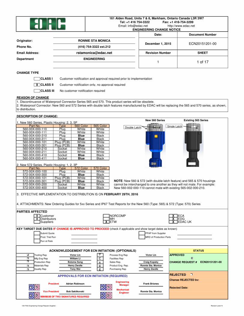
161 Alden Road, Units 7 & 8, Markham, Ontario Canada L3R 3W7
Tel: +1 416 754-3322 Fax: +1 416-754-3299
Email: [email protected] http://www.edac.net
ENGINEERING CHANGE NOTICE
Date: Document Number
Originator: RONNIE STA MONICADecember 1, 2015 ECN20151201-00
Phone No. (416) 754-3322 ext.212
1. New 560 Series, Plastic Housing: 2, 3, 5P
2. New 572 Series, Plastic Housing: 1, 2, 3P
Email Address: [email protected] Revision Number SHEET
Department ENGINEERING1 1 of 17
CLASS I Customer notification and approval required prior to implementation
CLASS II Customer notification only, no approval required
CLASS III No customer notification required
ECN20151201-00
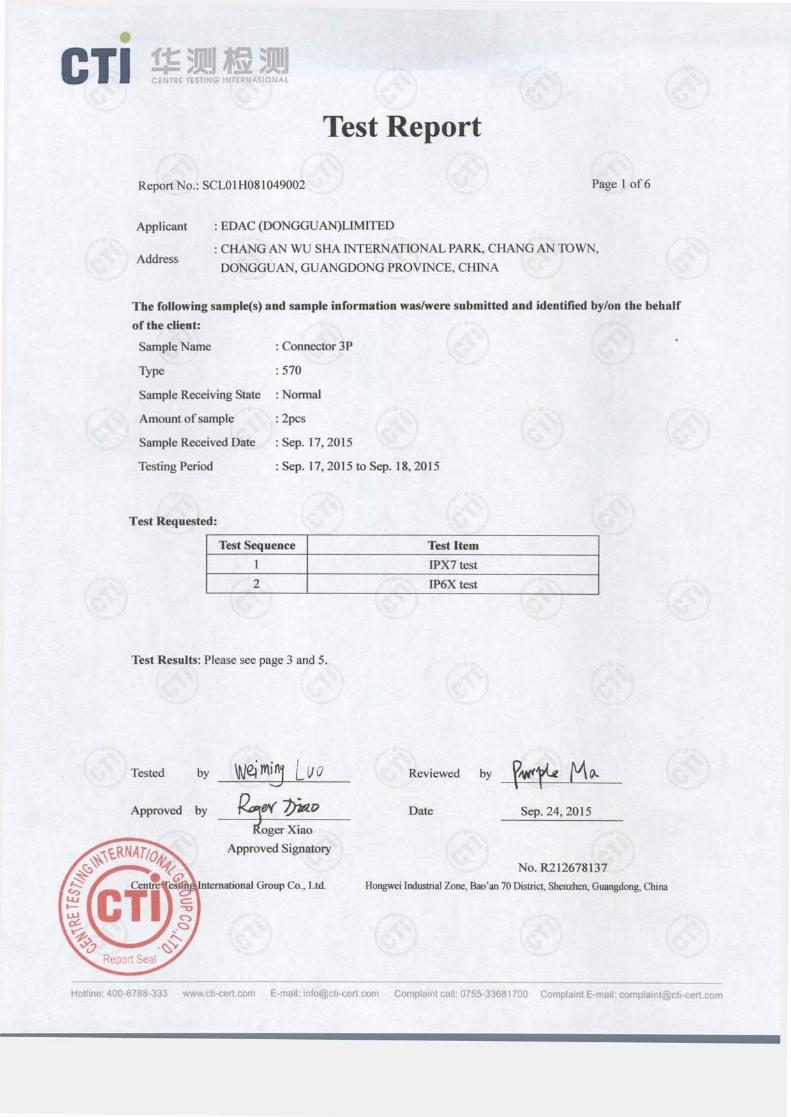
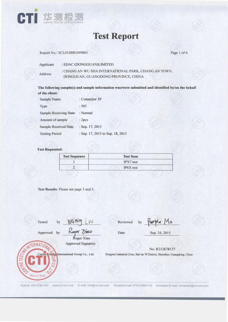
1. Discontinuance of Waterproof Connector Series 565 and 570. This product series will be obsolete.
2. Waterproof Connector: New 560 and 572 Series with double latch features manufactured by EDAC will be replacing the 565 and 570 series, as shown,
to distribution.
KEY TARGET DUE DATES IF CHANGE IS APPROVED TO PROCEED (check if applicable and show target dates as known)
Engineering
ManagerPresident
Materials Rep Product Eng. Rep.
Quality Rep Purchasing Rep
Henry Zwolle
Vice President Bob Sakitkovski Ronnie Sta. Monica
APPROVALS FOR ECN INITIATION (REQUIRED)
Type
MINIMUM OF TWO SIGNATURES REQUIRED
Plug (PCB) White
Plug (PCB)
Adrian Robinson Frank Briones
Mechanical
Engineer
Part No.
560-00X-000-110
560-00X-000-111
560-00X-000-310
560-00X-000-311
560-00X-000-210
560-00X-000-101
560-00X-000-301
Plug
Plug
Plug
Plug
Socket
560 Color
White
White
BlueBlue
White
White
Blue
565 Color
White
White
Black
Black
White
Black
White
BlueWhite
Black
560-00X-000-211
560-00X-000-410 Socket
Socket
572 Color 570 Color
572-00X-000-100 Plug White
560-00X-000-411 Socket Blue Black
Blue Black
572-00X-000-300 Plug Blue Black
White
Part No. Type
572-00X-000-101 Plug (PCB) White White
572-00X-000-301 Plug (PCB)
572-00X-000-200 Socket White White
ACKNOWLEDGEMENT FOR ECN INITIATION: (OPTIONALS)
3. EFFECTIVE IMPLEMENTATION TO DISTRIBUTION IS ON FEBRUARY 29TH, 2016
572-00X-000-400 Socket
STATUS
Blue Black
4. ATTACHMENTS: New Ordering Guides for 5xx Series and IP67 Test Reports for the New 560 (Type: 565) & 572 (Type: 570) Series
Craig Kopsky
William Li
Botoma Song
Tooling Rep Process Eng Rep Victor Lin
Ronnie Sta. Monica
Henry ZwolleTony Wei
Mfg Eng Rep Facilities Rep
Production Rep Sales Rep.
APPROVEDVictor Lin
NOTE: New 560 & 572 (with double latch feature) and 565 & 570 housings
cannot be interchanged to one another as they will not mate. For example:
New 560-002-000-110 cannot mate with existing 565-002-000-210.
New 560 Series Existing 565 Series
Double LatchSingle Latch
13A-F002 Engineering Change Request (Supplier) Revision Level: N
WATERPROOFCONNECTORS
IP Rated Wire-to-Wire, Wire-to-Board
Connect with Us...Experience Makes the Difference
Pages
2-3
2-3
4-5
4-5
6-7
8
9-10
9-10
11-12
13
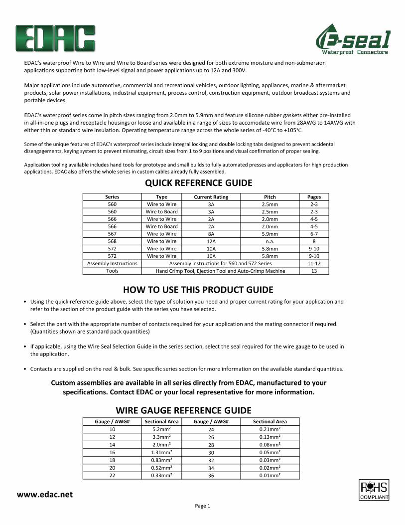
Series Type Current Rating Pitch
560 Wire to Wire 3A 2.5mm
560 Wire to Board 3A 2.5mm
566 Wire to Wire 2A 2.0mm
566 Wire to Board 2A 2.0mm
567 Wire to Wire 8A 5.9mm
24
568 Wire to Wire 12A n.a.
Assembly Instructions
Tools
Sectional Area Gauge / AWG# Sectional AreaGauge / AWG#
2.0mm²
10
12
14
5.2mm²
26 0.13mm²
22 0.33mm² 36 0.01mm²
16 1.31mm² 30 0.05mm²
20 0.52mm² 34 0.02mm²
0.08mm²28
18 0.83mm² 32 0.03mm²
572 Wire to Wire 10A 5.8mm
572 Wire to Wire 10A 5.8mm
Assembly instructions for 560 and 572 Series
Hand Crimp Tool, Ejection Tool and Auto-Crimp Machine
0.21mm²
3.3mm²
www.edac.net
QUICK REFERENCE GUIDE
• Using the quick reference guide above, select the type of solution you need and proper current rating for your application and
refer to the section of the product guide with the series you have selected.
• Select the part with the appropriate number of contacts required for your application and the mating connector if required.
(Quantities shown are standard pack quantities)
• If applicable, using the Wire Seal Selection Guide in the series section, select the seal required for the wire gauge to be used in
the application.
• Contacts are supplied on the reel & bulk. See specific series section for more information on the available standard quantities.
Custom assemblies are available in all series directly from EDAC, manufactured to your
specifications. Contact EDAC or your local representative for more information.
HOW TO USE THIS PRODUCT GUIDE
WIRE GAUGE REFERENCE GUIDE
EDAC's waterproof Wire to Wire and Wire to Board series were designed for both extreme moisture and non-submersion
applications supporting both low-level signal and power applications up to 12A and 300V.
Major applications include automotive, commercial and recreational vehicles, outdoor lighting, appliances, marine & aftermarket
products, solar power installations, industrial equipment, process control, construction equipment, outdoor broadcast systems and
portable devices.
EDAC's waterproof series come in pitch sizes ranging from 2.0mm to 5.9mm and feature silicone rubber gaskets either pre-installed
in all-in-one plugs and receptacle housings or loose and available in a range of sizes to accomodate wire from 28AWG to 14AWG with
either thin or standard wire insulation. Operating temperature range across the whole series of -40°C to +105°C.
Some of the unique features of EDAC's waterproof series include integral locking and double locking tabs designed to prevent accidental
disengagements, keying system to prevent mismating, circuit sizes from 1 to 9 positions and visual confirmation of proper sealing.
Application tooling available includes hand tools for prototype and small builds to fully automated presses and applicators for high production
applications. EDAC also offers the whole series in custom cables already fully assembled.
Page 1
AWG# Ins. Dia. Pcs/Reel
20-22 Max. Ø1.7 8,000
22-28 Max. Ø1.6 8,000
AWG# Ins. Dia. Pcs/Reel
20-22 Max. Ø1.7 8,000
Housing 22-28 Max. Ø1.6 10,000
Contact
Housing
Contact
Wire O.D. Color
565-290-711
565-290-721
Ø1.00 to
Ø1.30
PCB Thickness
565-290-731
565-290-741
Yellow
Ø1.30 to
Ø1.70Orange
Crimp &
Poke
Applicable Contact
Part No
565-290-741
565-290-721
1.6mm
565-200-100
PBT with Glass, UL 94V-0
15 mΩ max
-40°C to +105°C
PBT, UL 94V-0
Part No.
Insulation Resistance
Temperature Range
1000 MΩ min./DC500V
Phosphor Bronze
Contact Plating Tin Plating
Brass
Wire & Housing Seals Silicone Rubber
PCB
Header
Waterproofing Cap PBT, UL 94V-0
Male Contact (Pin)
Female Contact (Socket)
Pitch
250V
2.5mm
Withstanding Voltage
Rated Voltage
Part No
565-290-731
565-290-711
No. of Positions 2, 3, 5P
Rated Current
1000V AC (rms)
3A max
Contact Resistance
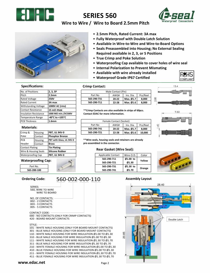
SERIES 560
Ordering Code:
www.edac.net
Waterproofing Cap:
Wire to Wire / Wire to Board 2.5mm Pitch
• 2.5mm Pitch, Rated Current: 3A max
• Fully Waterproof with Double Latch Solution
• Available in Wire-to-Wire and Wire-to-Board Options
• Seals Preassembled into Housing; No External Sealing
Required available in 2, 3, or 5 Positions
• True Crimp and Poke Solution
• Waterproofing Cap available to cover holes of wire seal
• Internal Polarization to Prevent Mismating
• Available with wire already installed
• Waterproof Grade IP67 Certified
Specifications: Crimp Contact:
**Crimp Contacts are also available in strips of 60pcs.
Contact EDAC for more information.
Rear Gasket (Wire Seal):
NO. OF CONTACTS:002 - 2 CONTACTS003 - 3 CONTACTS005 - 5 CONTACTS
CONTACT CODE:000 - NO CONTACTS (ONLY FOR CRIMP CONTACTS)420 - BOARD MOUNT CONTACTS
STYLE:101 - WHITE MALE HOUSING (ONLY FOR BOARD MOUNT CONTACTS)301 - BLUE MALE HOUSING (ONLY FOR BOARD MOUNT CONTACTS)
110 - WHITE MALE HOUSING FOR WIRE INSULATION Ø1.00 TO Ø1.30
310 - BLUE MALE HOUSING FOR WIRE INSULATION Ø1.00 TO Ø1.30
111 - WHITE MALE HOUSING FOR WIRE INSULATION Ø1.30 TO Ø1.70
311 - BLUE MALE HOUSING FOR WIRE INSULATION Ø1.30 TO Ø1.70
210 - WHITE FEMALE HOUSING FOR WIRE INSULATION Ø1.00 TO Ø1.30
410 - BLUE FEMALE HOUSING FOR WIRE INSULATION Ø1.00 TO Ø1.30
211 - WHITE FEMALE HOUSING FOR WIRE INSULATION Ø1.30 TO Ø1.70
411 - BLUE FEMALE HOUSING FOR WIRE INSULATION Ø1.30 TO Ø1.70
560-002-000-110SERIES:560, WIRE TO WIRE WIRE TO BOARD
Assembly Layout
Materials:
Double Latch
28.40
20
.85
**Wire seals, housing seals and retainers are already
pre-assembled in the connector.
Page 2
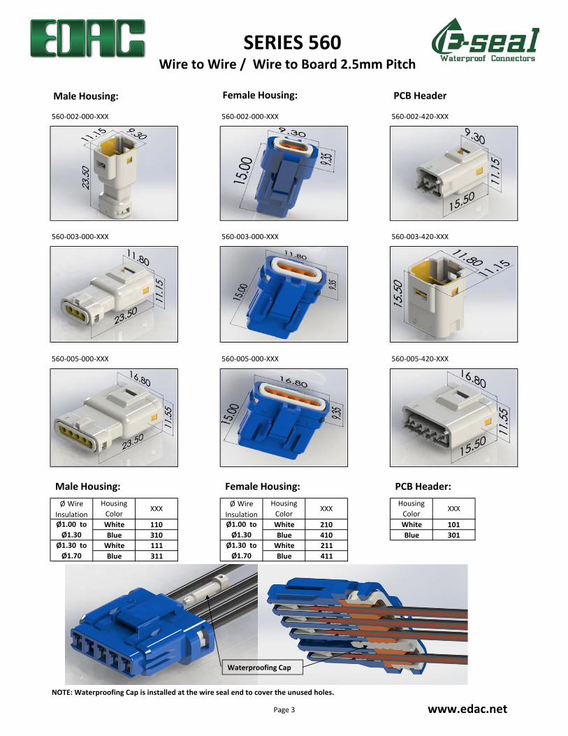
560-002-000-XXX 560-002-000-XXX 560-002-420-XXX
560-003-000-XXX 560-003-000-XXX 560-003-420-XXX
560-005-000-XXX 560-005-000-XXX 560-005-420-XXX
White 110 White 210 White 101
Blue 310 Blue 410 Blue 301
White 111 White 211
Blue 311 Blue 411
NOTE: Waterproofing Cap is installed at the wire seal end to cover the unused holes.
Ø1.30 to
Ø1.70
Ø1.00 to
Ø1.30
Ø1.30 to
Ø1.70
Ø1.00 to
Ø1.30
XXXØ Wire
Insulation
Housing
ColorXXX
Housing
Color
Housing
Color
Ø Wire
InsulationXXX
SERIES 560
www.edac.net
Wire to Wire / Wire to Board 2.5mm Pitch
Male Housing: Female Housing: PCB Header
Waterproofing Cap
Male Housing: Female Housing: PCB Header:
Page 3
AWG# Ins. Dia. Pcs/Reel
22-28 Ø1.0~Ø1.5 12,000
AWG# Ins. Dia. Pcs/Reel
22-28 Ø1.0~Ø1.5 12,000
Housing
Contact
Housing
Contact
Wire O.D. Color
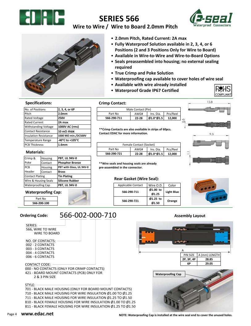
PIN SIZE A (mm) LENGTH
2P, 3P, 4P 28.85
6P 29.05
NOTE: Waterproofing Cap is installed at the wire seal end to cover the unused holes.
Withstanding Voltage 1000V AC (rms)
No. of Positions 2, 3, 4, or 6P Male Contact (Pin)
Pitch 2.0mm Part No
Rated Voltage 250V 566-290-711
Rated Current 2A max
Crimp &
Poke
PBT, UL 94V-0
Phosphor Bronze
Contact Resistance 10 mΩ max
Insulation Resistance 1000 MΩ min./DC500V
Temperature Range -40°C to +105°C
PCB Thickness 1.6mm Female Contact (Socket)
Part No
566-290-721
Light Blue
PCB
Header
PBT with Glass, UL 94V-0
Brass
Contact Plating Tin Plating
Wire & Housing Seals Silicone Rubber
Waterproofing Cap PBT, UL 94V-0 Applicable Contact
566-290-711Ø1.00 to
Ø1.25
Part No566-290-721
Ø1.25 to
Ø1.50Orange
566-200-100
SERIES:566, WIRE TO WIRE WIRE TO BOARD
566-002-000-710
NO. OF CONTACTS:002 - 2 CONTACTS003 - 3 CONTACTS004 - 4 CONTACTS006 - 6 CONTACTS
CONTACT CODE:000 - NO CONTACTS (ONLY FOR CRIMP CONTACTS)421 - BOARD MOUNT CONTACTS (PCB) ONLY FOR 2 & 3 PIN SIZE
STYLE:701 - BLACK MALE HOUSING (ONLY FOR BOARD MOUNT CONTACTS)
710 - BLACK MALE HOUSING FOR WIRE INSULATION Ø1.00 TO Ø1.25
711 - BLACK MALE HOUSING FOR WIRE INSULATION Ø1.25 TO Ø1.50
810 - BLACK FEMALE HOUSING FOR WIRE INSULATION Ø1.00 TO Ø1.25
811 - BLACK FEMALE HOUSING FOR WIRE INSULATION Ø1.25 TO Ø1.50
SERIES 566
Ordering Code:
www.edac.net
Waterproofing Cap:
• 2.0mm Pitch, Rated Current: 2A max
• Fully Waterproof Solution available in 2, 3, 4, or 6
Positions (2 and 3 Positions Only for Wire to Board)
• Available in Wire-to-Wire and Wire-to-Board Options
• Seals preassembled into housing; no external sealing
required
• True Crimp and Poke Solution
• Waterproofing cap available to cover holes of wire seal
• Available with wire already installed
• Waterproof Grade IP67 Certified
Specifications: Crimp Contact:
**Crimp Contacts are also available in strips of 60pcs.
Contact EDAC for more information.
Rear Gasket (Wire Seal):
Assembly Layout
A
Wire to Wire / Wire to Board 2.0mm Pitch
Waterproofing Cap
Materials:
**Wire seals and housing seals are already
pre-assembled in the connector.
Page 4
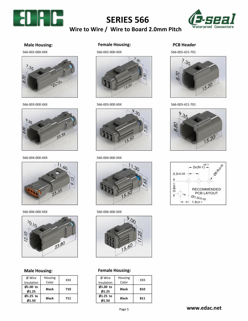
566-002-000-XXX 566-002-000-XXX 566-002-421-701
566-003-000-XXX 566-003-000-XXX 566-003-421-701
566-004-000-XXX 566-004-000-XXX
566-006-000-XXX 566-006-000-XXX
Ø1.00 to
Ø1.25Black
Ø1.25 to
Ø1.50
810
Ø Wire
Insulation
Housing
ColorXXX
Ø Wire
Insulation
Housing
Color
Black 711Ø1.25 to
Ø1.50Black 811
XXX
Ø1.00 to
Ø1.25Black 710
SERIES 566
www.edac.net
Wire to Wire / Wire to Board 2.0mm Pitch
±0.1
RECOMMENDED
PCB LAYOUT
Ø0.
8±0.0
5
Ø1.0±0.05
2.8
±0.1
1.6±0.1
2.0±0.05
2x(N-1)
Male Housing: Female Housing: PCB Header
Male Housing: Female Housing:
Page 5
AWG# Ins. Dia. Pcs/Reel
14 Max. Ø3.1 4,000
20-16 Max. Ø3.1 4,000
20-16 Max. Ø3.1 4,000
22-20 Max. Ø2.7 4,000
AWG# Ins. Dia. Pcs/Reel
14 Max. Ø3.1 4,000
20-16 Max. Ø3.1 4,000
20-16 Max. Ø3.1 4,000
22-20 Max. Ø2.7 4,000
22-20 Max. Ø2.7 4,000
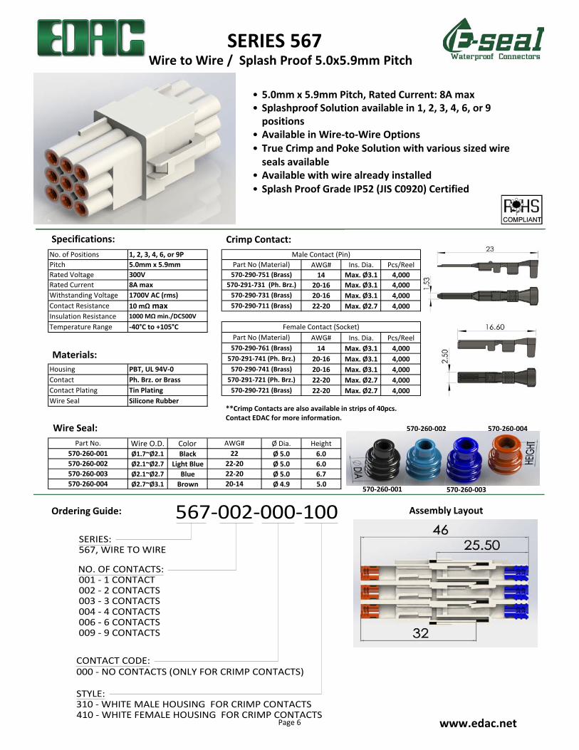
Wire O.D. Color Ø Dia. Height
Ø1.7~Ø2.1 Black Ø 5.0 6.0
Ø2.1~Ø2.7 Light Blue Ø 5.0 6.0
Ø2.1~Ø2.7 Blue Ø 5.0 6.7
Ø2.7~Ø3.1 Brown Ø 4.9 5.0
No. of Positions 1, 2, 3, 4, 6, or 9P Male Contact (Pin)
Pitch 5.0mm x 5.9mm Part No (Material)
Rated Voltage 300V 570-290-751 (Brass)
Rated Current 8A max 570-291-731 (Ph. Brz.)
Part No (Material)
Withstanding Voltage 1700V AC (rms) 570-290-731 (Brass)
Contact Resistance 10 mΩ max 570-290-711 (Brass)
Insulation Resistance 1000 MΩ min./DC500V
Temperature Range -40°C to +105°C Female Contact (Socket)
Part No. AWG#
570-290-761 (Brass)
570-291-741 (Ph. Brz.)
Housing PBT, UL 94V-0 570-290-741 (Brass)
Contact Ph. Brz. or Brass 570-291-721 (Ph. Brz.)
Contact Plating Tin Plating 570-290-721 (Brass)
Wire Seal Silicone Rubber
570-260-004 20-14
570-260-001 22
570-260-002 22-20
570-260-003 22-20
SERIES 567
www.edac.net
Wire to Wire / Splash Proof 5.0x5.9mm Pitch
• 5.0mm x 5.9mm Pitch, Rated Current: 8A max
• Splashproof Solution available in 1, 2, 3, 4, 6, or 9
positions
• Available in Wire-to-Wire Options
• True Crimp and Poke Solution with various sized wire
seals available
• Available with wire already installed
• Splash Proof Grade IP52 (JIS C0920) Certified
Ordering Guide: 567-002-000-100
NO. OF CONTACTS:001 - 1 CONTACT002 - 2 CONTACTS003 - 3 CONTACTS004 - 4 CONTACTS006 - 6 CONTACTS009 - 9 CONTACTS
CONTACT CODE:000 - NO CONTACTS (ONLY FOR CRIMP CONTACTS)
STYLE:310 - WHITE MALE HOUSING FOR CRIMP CONTACTS410 - WHITE FEMALE HOUSING FOR CRIMP CONTACTS
SERIES:567, WIRE TO WIRE
Assembly Layout
Specifications: Crimp Contact:
**Crimp Contacts are also available in strips of 40pcs.
Contact EDAC for more information.
Wire Seal:
Materials:
570-260-001
570-260-002 570-260-004
570-260-003
Page 6
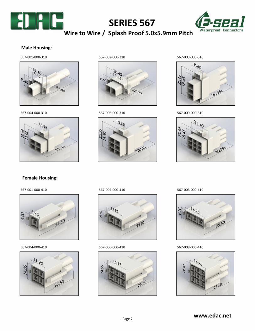
567-001-000-310 567-002-000-310 567-003-000-310
567-004-000-310 567-006-000-310 567-009-000-310
567-001-000-410 567-002-000-410 567-003-000-410
567-004-000-410 567-006-000-410 567-009-000-410
SERIES 567
www.edac.net
Male Housing:
Female Housing:
Wire to Wire / Splash Proof 5.0x5.9mm Pitch
Page 7
AWG# Ins. Dia. Pcs/Reel
14 Max. Ø3.1 4,000
20-16 Max. Ø3.1 4,000
20-16 Max. Ø3.1 4,000
22-20 Max. Ø2.7 4,000
AWG# Ins. Dia. Pcs/Reel
14 Max. Ø3.1 4,000
20-16 Max. Ø3.1 4,000
20-16 Max. Ø3.1 4,000
22-20 Max. Ø2.7 4,000
22-20 Max. Ø2.7 4,000
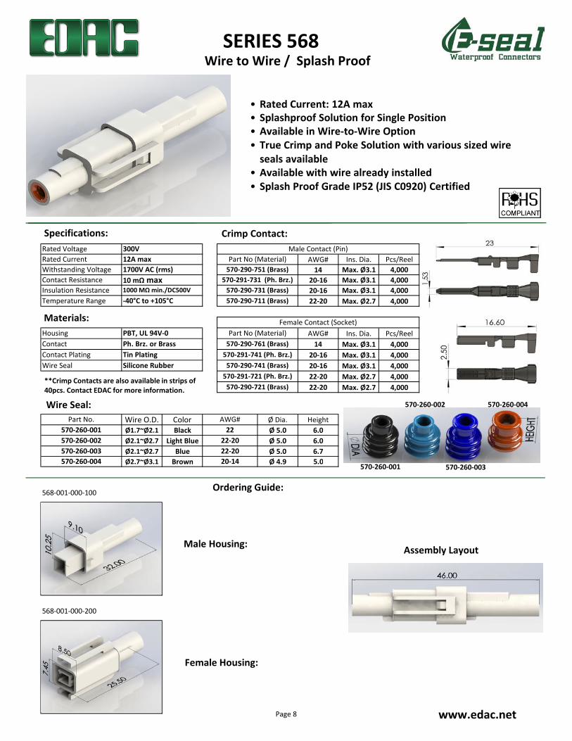
Wire O.D. Color Ø Dia. Height
Ø1.7~Ø2.1 Black Ø 5.0 6.0
Ø2.1~Ø2.7 Light Blue Ø 5.0 6.0
Ø2.1~Ø2.7 Blue Ø 5.0 6.7
Ø2.7~Ø3.1 Brown Ø 4.9 5.0
568-001-000-100
568-001-000-200
Rated Voltage 300V Male Contact (Pin)
Rated Current 12A max Part No (Material)
Withstanding Voltage 1700V AC (rms) 570-290-751 (Brass)
Contact Resistance 10 mΩ max 570-291-731 (Ph. Brz.)
Insulation Resistance 1000 MΩ min./DC500V 570-290-731 (Brass)
Temperature Range -40°C to +105°C 570-290-711 (Brass)
Female Contact (Socket)
Housing PBT, UL 94V-0 Part No (Material)
Contact Ph. Brz. or Brass 570-290-761 (Brass)
Contact Plating Tin Plating 570-291-741 (Ph. Brz.)
Wire Seal Silicone Rubber 570-290-741 (Brass)
570-291-721 (Ph. Brz.)
570-290-721 (Brass)
Part No. AWG#
570-260-001 22
570-260-002 22-20
570-260-003 22-20
570-260-004 20-14
SERIES 568
Ordering Guide:
www.edac.net
Assembly Layout
Wire to Wire / Splash Proof
• Rated Current: 12A max
• Splashproof Solution for Single Position
• Available in Wire-to-Wire Option
• True Crimp and Poke Solution with various sized wire
seals available
• Available with wire already installed
• Splash Proof Grade IP52 (JIS C0920) Certified
Male Housing:
Female Housing:
Specifications: Crimp Contact:
**Crimp Contacts are also available in strips of
40pcs. Contact EDAC for more information.
Materials:
Wire Seal:
570-260-001
570-260-002 570-260-004
570-260-003
Page 8

AWG# Ins. Dia. Pcs/Reel
14 Max. Ø3.1 4,000
20-16 Max. Ø3.1 4,000
20-16 Max. Ø3.1 4,000
22-20 Max. Ø2.7 4,000
AWG# Ins. Dia. Pcs/Reel
14 Max. Ø3.1 4,000
20-16 Max. Ø3.1 4,000
Housing 20-16 Max. Ø3.1 4,000
Contact 22-20 Max. Ø2.7 4,000
Housing 22-20 Max. Ø2.7 4,000
Contact
Wire O.D. Color Ø Dia. Height
Ø1.7~Ø2.1 Black Ø 5.0 6.0
Ø2.1~Ø2.7 Light Blue Ø 5.0 6.0
Ø2.1~Ø2.7 Blue Ø 5.0 6.7
Ø2.7~Ø3.1 Brown Ø 4.9 5.0
No. of Positions 1, 2, 3P Male Contact (Pin)
Pitch 5.8mm Part No (Material)
Rated Voltage 300V 570-290-751 (Brass)
Rated Current 10A max 570-291-731 (Ph. Brz.)
PCB Thickness 1.6mm Part No (Material)
Withstanding Voltage 1700V AC (rms) 570-290-731 (Brass)
Contact Resistance 10 mΩ max 570-290-711 (Brass)
Insulation Resistance 1000 MΩ min./DC500V
Temperature Range -40°C to +105°C Female Contact (Socket)
570-290-761 (Brass)
570-291-741 (Ph. Brz.)
Crimp &
Poke
PBT, UL 94V-0 570-290-741 (Brass)
Ph. Brz. or Brass 570-291-721 (Ph. Brz.)
PCB HeaderPBT with Glass, UL 94V-0 570-290-721 (Brass)
Brass
Contact Plating Tin Plating
Wire & Housing Seals Silicone Rubber
Part No. AWG#
570-260-001 22
570-260-002 22-20
570-260-003 22-20
570-260-004 20-14
SERIES 572
Ordering Guide:
www.edac.net
Wire to Wire / Wire to Board 5.8mm Pitch
• 5.8mm Pitch, Rated Current: 10A max
• Fully Waterproof with Double Latch Solution
• Available in Wire-to-Wire and Wire-to-Board Options
• Seals preassembled into housing; no external sealing
required available in 1, 2, or 3 Positions
• True Crimp and Poke Solution
• Internal Polarization to Prevent Mismating
• Available with wire already installed
• Wide range of wire sizes available
• Waterproof Grade IP67 Certified
Specifications: Crimp Contact:
**Crimp Contacts are also available in strips of 40pcs.
Contact EDAC for more information.
**Housing seals are already pre-assembled in the
connector.Wire Seal:
NO. OF CONTACTS:001 - 1 CONTACT002 - 2 CONTACTS003 - 3 CONTACTS
CONTACT CODE:000 - NO CONTACTS (ONLY FOR CRIMP CONTACTS)420 - BOARD MOUNT CONTACTS
STYLE:101 - WHITE MALE HOUSING (ONLY FOR BOARD MOUNT CONTACTS)301 - BLUE MALE HOUSING (ONLY FOR BOARD MOUNT CONTACTS)100 - WHITE MALE HOUSING FOR CRIMP CONTACTS300 - BLUE MALE HOUSING FOR CRIMP CONTACTS200 - WHITE FEMALE HOUSING FOR CRIMP CONTACTS400 - BLUE FEMALE HOUSING FOR CRIMP CONTACTS
572-002-000-100SERIES:572, WIRE TO WIRE WIRE TO BOARD
Assembly Layout
Materials:
570-260-001
570-260-002 570-260-004
570-260-003
Double Latch
47.0
30.5
Page 9
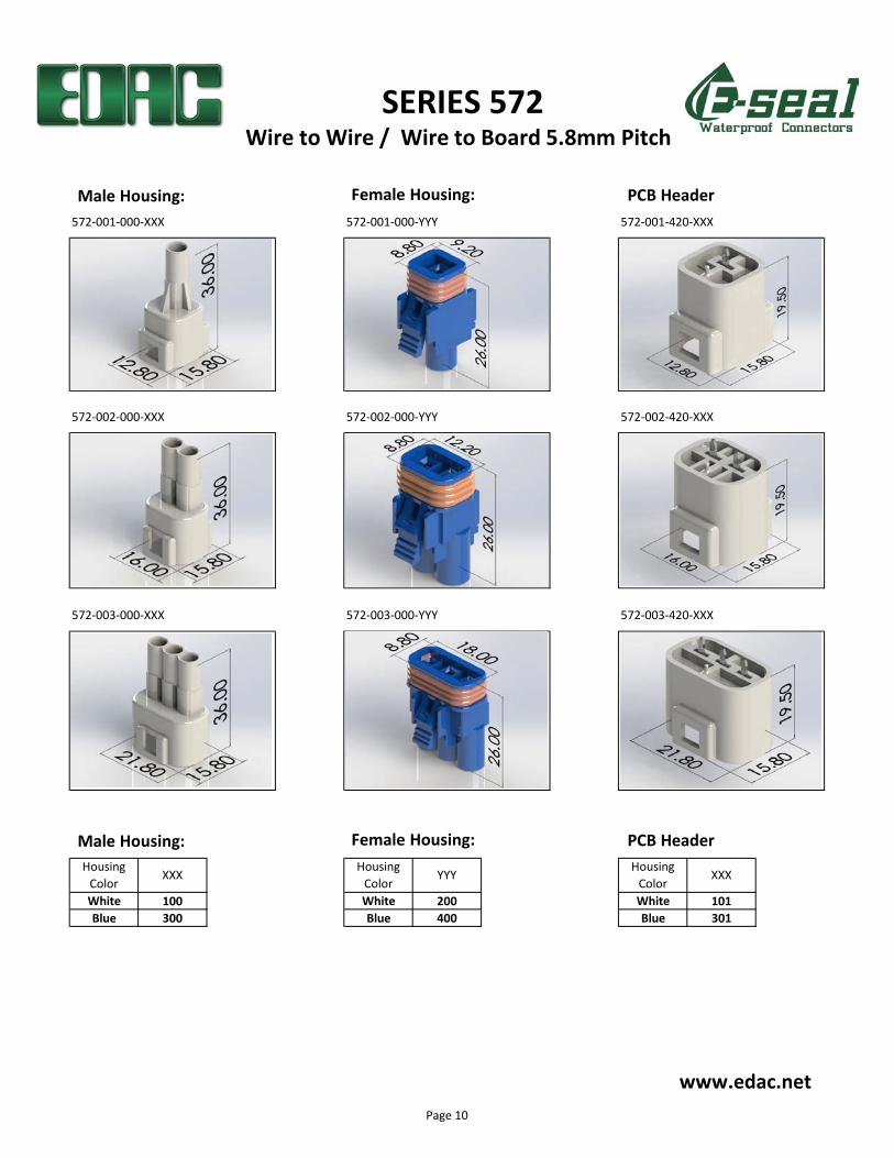
572-001-000-XXX 572-001-000-YYY 572-001-420-XXX
572-002-000-XXX 572-002-000-YYY 572-002-420-XXX
572-003-000-XXX 572-003-000-YYY 572-003-420-XXX
White 100 White 200 White 101
Blue 300 Blue 400 Blue 301
Housing
ColorXXX
Housing
ColorYYY
Housing
ColorXXX
SERIES 572
www.edac.net
Wire to Wire / Wire to Board 5.8mm Pitch
Male Housing: Female Housing: PCB Header
Male Housing: Female Housing: PCB Header
Page 10
www.edac.net
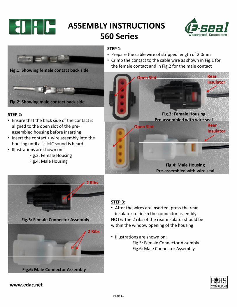
STEP 1:
• Prepare the cable wire of stripped length of 2.0mm
• Crimp the contact to the cable wire as shown in Fig.1 for
the female contact and in Fig.2 for the male contact
ASSEMBLY INSTRUCTIONS
560 Series
Fig.1: Showing female contact back side
Fig.2: Showing male contact back side
STEP 2:
• Ensure that the back side of the contact is
aligned to the open slot of the pre-
assembled housing before inserting
• Insert the contact + wire assembly into the
housing until a "click" sound is heard.
• Illustrations are shown on:
Fig.3: Female Housing
Fig.4: Male Housing
Fig.3: Female Housing
Pre-assembled with wire seal
Fig.4: Male Housing
Pre-assembled with wire seal
Open Slot
Open Slot
Rear
Insulator
Rear
Insulator
STEP 3:
• After the wires are inserted, press the rear
insulator to finish the connector assembly
NOTE: The 2 ribs of the rear insulator should be
within the window opening of the housing
• Illustrations are shown on:
Fig.5: Female Connector Assembly
Fig.6: Male Connector Assembly
Fig.5: Female Connector Assembly
Fig.6: Male Connector Assembly
2 Ribs
2 Ribs
Page 11
www.edac.net
ASSEMBLY INSTRUCTIONS
Fig.7
572 Series
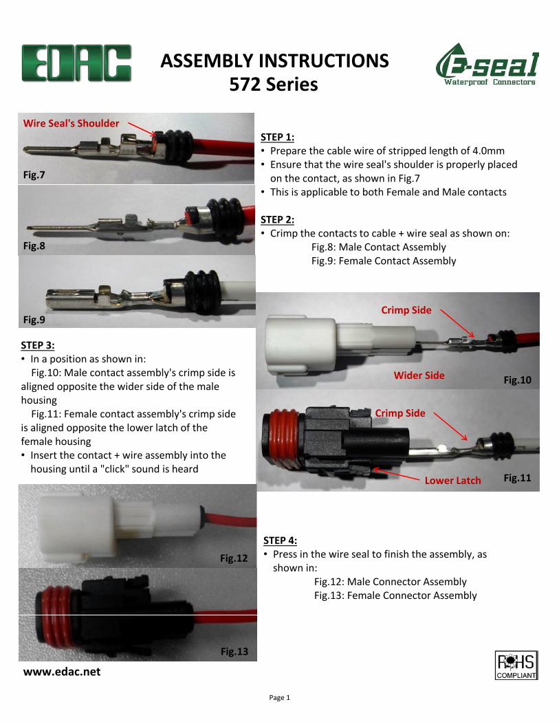
STEP 1:
• Prepare the cable wire of stripped length of 4.0mm
• Ensure that the wire seal's shoulder is properly placed
on the contact, as shown in Fig.7
• This is applicable to both Female and Male contacts
STEP 2:
• Crimp the contacts to cable + wire seal as shown on:
Fig.8: Male Contact Assembly
Fig.9: Female Contact Assembly
Wire Seal's Shoulder
Fig.8
Fig.9
STEP 3:
• In a position as shown in:
Fig.10: Male contact assembly's crimp side is
aligned opposite the wider side of the male
housing
Fig.11: Female contact assembly's crimp side
is aligned opposite the lower latch of the
female housing
• Insert the contact + wire assembly into the
housing until a "click" sound is heardFig.11
Fig.10
Crimp Side
Crimp Side
Wider Side
Lower Latch
STEP 4:
• Press in the wire seal to finish the assembly, as
shown in:
Fig.12: Male Connector Assembly
Fig.13: Female Connector Assembly
Fig.12
Fig.13
Page 1
www.edac.net
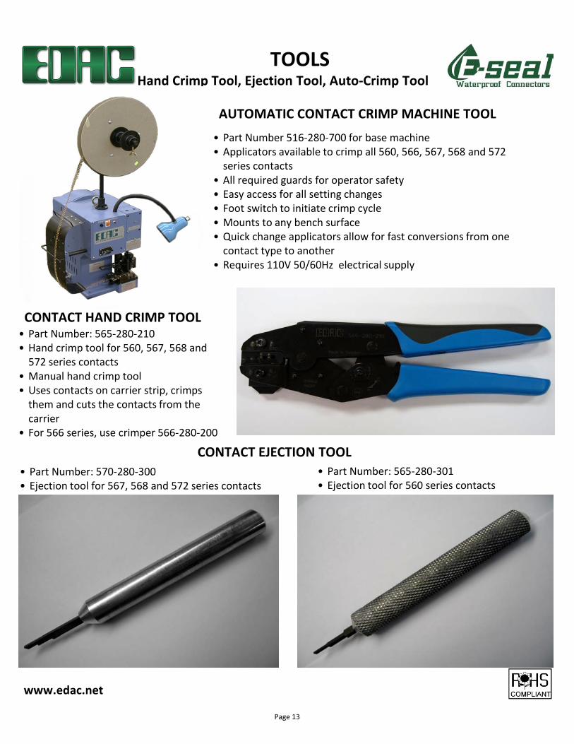
AUTOMATIC CONTACT CRIMP MACHINE TOOL
CONTACT HAND CRIMP TOOL
TOOLSHand Crimp Tool, Ejection Tool, Auto-Crimp Tool
• Part Number 516-280-700 for base machine
• Applicators available to crimp all 560, 566, 567, 568 and 572
series contacts
• All required guards for operator safety
• Easy access for all setting changes
• Foot switch to initiate crimp cycle
• Mounts to any bench surface
• Quick change applicators allow for fast conversions from one
contact type to another
• Requires 110V 50/60Hz electrical supply
• Part Number: 565-280-210
• Hand crimp tool for 560, 567, 568 and
572 series contacts
• Manual hand crimp tool
• Uses contacts on carrier strip, crimps
them and cuts the contacts from the
carrier
• For 566 series, use crimper 566-280-200
CONTACT EJECTION TOOL
• Part Number: 565-280-301
• Ejection tool for 560 series contacts
• Part Number: 570-280-300
• Ejection tool for 567, 568 and 572 series contacts
Page 13