Embed Size (px)
Citation preview

Eclipse User Manual
Part number 141045 Manual/Software Release 4.0.2 8 May, 2018 2001-9 Eventide Inc., One Alsan Way, Little Ferry, NJ 07643 USA Harmonizer is a registered trademark of Eventide Inc. for its audio special effects devices incorporating pitch shift. Eventide, Eclipse, Orville ,and UltraShifter are trademarks of Eventide Inc. Windows is a trademark of Microsoft Inc., ADAT is a trademark of Alesis Inc., CompactFlash is a trademark of SanDisk Corporation.

This page is intentionally left blank
Eclipse User Manual - Contents
Release 4.0.1 Page 1 of 66 Eclipse User Manual
The Hows and Whys of This Manual................................................................................................... 5 Overviews, Basic Information, and Quickstart ...................................................................................... 6
The Big Picture – A Must-Read .............................................................................................................. 6 Knobs, Keys, and Jacks ........................................................................................................................... 7
The Front Panel .................................................................................................................................... 7 The Back Panel..................................................................................................................................... 9
Getting Around and Altering Parameters .............................................................................................. 11 The “Areas” (e.g. – Levels, Program, Setup, etc.) ............................................................................. 11 Understanding the Display and Soft Keys ......................................................................................... 12
The Bottom Line of the Display ......................................................................................................................................................... 12 The Top Line of the Display ............................................................................................................................................................... 13
Altering Parameters ............................................................................................................................ 13 Quickstart............................................................................................................................................... 14
Hooking Up To the Outside World .................................................................................................... 14 Analog Connections ........................................................................................................................................................................... 14 Digital Connections ........................................................................................................................................................................... 14
Choosing Effects ................................................................................................................................ 15 Altering the Effects ............................................................................................................................ 15
Tempo ................................................................................................................................................................................................ 15 Tempo Mode ...................................................................................................................................................................................... 16 Tempo-Controlled Parameters: T_DELAY, T_RATE, etc. ................................................................................................................. 16
Tutorial 1: Loading a Program, Setting the Tempo, and Assigning Modulation ......................................................................................................................................... 16 Tutorial 2: Creating a Program “from Scratch” and Assigning a Hot Key ..................................................................................................................................................... 19
Operation ................................................................................................................................................. 20 Mounting and Handling ..................................................................................................................... 20 Memory Cards .................................................................................................................................... 20 The Display Brightness and Click Features ....................................................................................... 20
Global Signal Flow and Levels ............................................................................................................. 21 Using the Meters ................................................................................................................................ 21 Input and Output Modes (Global Stereo or Global Mono?) .............................................................. 22 Global Wet/Dry Mix .......................................................................................................................... 22 Global Levels ..................................................................................................................................... 22 Bypassing and Muting ........................................................................................................................ 24
Digital Setup .......................................................................................................................................... 24 Digital Input ....................................................................................................................................... 24 Internal and External Clock Source ................................................................................................... 25
Using Higher Sampling Rates Disables Some Programs .................................................................................................................. 26 Digital Output ..................................................................................................................................... 26
ADAT Output or Two-Channel Optical Output? ............................................................................................................................... 27 Program Operations - Load, Save, Remove, etc.................................................................................... 28
Sorting and Loading Programs ........................................................................................................... 28 Loading Programs From MIDI ......................................................................................................................................................... 29 Using MIDI Maps ............................................................................................................................................................................. 29 Using MIDI Bank Select Messages .................................................................................................................................................... 30
Saving and Updating Programs .......................................................................................................... 30
Eclipse User Manual - Contents
Eclipse User Manual Page 2 of 66 Release 4.0.1
Saving Programs ............................................................................................................................................................................... 30 Updating Programs ........................................................................................................................................................................... 31 Comparing the Current Program with the Saved Program ............................................................................................................... 31 User Groups ...................................................................................................................................................................................... 31
Removing Programs ........................................................................................................................... 31 Removing ALL Your Saved Programs ............................................................................................................................................... 31 Checking free space in internal memory or a card ............................................................................................................................ 31
Copying and Protecting Programs...................................................................................................... 32 Naming Things – The Mechanics ...................................................................................................... 32
Parameters ............................................................................................................................................. 33 Hot Keys ............................................................................................................................................. 33
Assigning Hot Keys ........................................................................................................................................................................... 33 Renaming Hot Keys ........................................................................................................................................................................... 34 Deleting Hot Keys ............................................................................................................................................................................. 34
Altering Parameters in the PARAMETER Area ................................................................................ 34 Master Parameters: M_LEVEL, M_DELAY, M_FBACK, etc. .......................................................................................................... 34 Tempo-based Parameters: T_RATE, T_DELAY, T_TAP, etc. ........................................................................................................... 35 Envelope-following Parameters: SENS, ATTACK, and DECAY ....................................................................................................... 36 LFO Parameters ................................................................................................................................................................................ 36 Sends and “Manual” Parameters ..................................................................................................................................................... 37
Routing and Levels between Effects Blocks ...................................................................................... 37 Routing .............................................................................................................................................................................................. 38 Wet/Dry Ratio .................................................................................................................................................................................... 39 Output Level ...................................................................................................................................................................................... 39 Bypassing Effects Blocks ................................................................................................................................................................... 39
Loading Different Algorithms into Effects Blocks ............................................................................ 39 Modulating Parameters Via the modulation block: LFO, ADSR, Envelope, MIDI, Pedals, and More ....................................................................................................... 40
Patching a Parameter to the Modulation Block’s “Modules” .......................................................................................................... 40 Scaling Modules and Selecting Modulation TYPE ............................................................................................................................ 41
Setting Up the Modulation Block....................................................................................................... 43 The Modulation Block ....................................................................................................................................................................... 43
More on modulation ........................................................................................................................... 44 External Controllers ........................................................................................................................... 45 Dedicated External Controllers .......................................................................................................... 47
Setting the Trigger Switch Mode ....................................................................................................................................................... 47 Reversing a controller ....................................................................................................................................................................... 47
MIDI Setup ......................................................................................................................................... 48 The Rear Panel Pedal Jacks .............................................................................................................................................................. 49
Storing and Loading Setups ................................................................................................................... 50 Utilities .................................................................................................................................................. 51
Transmitting and Receiving Data via the Serial Port ......................................................................... 51 Dumping Data Via the MIDI and Serial Ports ................................................................................... 51 Bulk Copying Programs ..................................................................................................................... 52 Fixing and Initializing Internal Memory ............................................................................................ 53 Fixing Strange Behavior, Freezes, Etc. .............................................................................................. 53 Formatting Memory Cards ................................................................................................................. 54 Word Clock Termination ................................................................................................................... 55 Updating Software.............................................................................................................................. 56
Creating an “Upgrade Card” ........................................................................................................................................................... 56 Updating with a Memory Card .......................................................................................................................................................... 56 Upgrade via the OUpdate Application .............................................................................................................................................. 56 Finding Out The Current Software Version....................................................................................................................................... 57
Approved CompactFlash Cards ......................................................................................................... 57 Electrical Specifications.......................................................................................................................... 58
Eclipse User Manual- Contents
Release 4.0.1 Page 3 of 66 Eclipse User Manual
Sample Rates ..................................................................................................................................................................................... 58 Frequency Response .......................................................................................................................................................................... 58 Digital Inputs/Outputs ....................................................................................................................................................................... 58 Analog Input (XLR Balanced Inputs) ................................................................................................................................................. 58 Analog Output ................................................................................................................................................................................... 58 Remote Control Inputs ....................................................................................................................................................................... 58 MIDI Connections ............................................................................................................................................................................. 58 Power ................................................................................................................................................................................................ 59 Size .................................................................................................................................................................................................... 59 Weight ................................................................................................................................................................................................ 59
Warranty Information............................................................................................................................ 60 What the warranty does and does not cover ...................................................................................................................................... 60 Who is covered under the warranty ................................................................................................................................................... 60 When the warranty becomes effective ................................................................................................................................................ 60 Who performs warranty work ............................................................................................................................................................ 61 Shipping within the 50 United States ................................................................................................................................................. 61 Shipping outside the 50 United States ............................................................................................................................................... 61
Index ......................................................................................................................................................... 63

Eclipse User Manual - Contents
Eclipse User Manual Page 4 of 66 Release 4.0.1
This page is intentionally left blank
Eclipse User Manual
Release 4.0.1 Page 5 of 66 Eclipse User Manual
The Hows and Whys of This Manual
Of course you have more exiting things to do than to read this manual. For one thing, you have Eventide’s fabulous new Eclipse Harmonizer brand processor waiting to effect all those sounds so badly in need of effecting. While the Eclipse is engineered for intuitive, user-friendly operation, reading this manual, either in part or in whole, will help clarify and illuminate its vast array of powerful features. Here’s how we’ve made that as painless a process as possible: • The Overview and Quickstart section will get you up and running fast, with references to the more in-
depth discussions contained in the Operation section. If you’re really in a hurry, skip to the tutorial on page 16...
• The Operation section will answer all of your in-depth questions with a complete, tedium-free discus-sion of all of the Eclipse’s potent features.
• The Table of Contents and Index will direct you to topics of interest with dispatch.
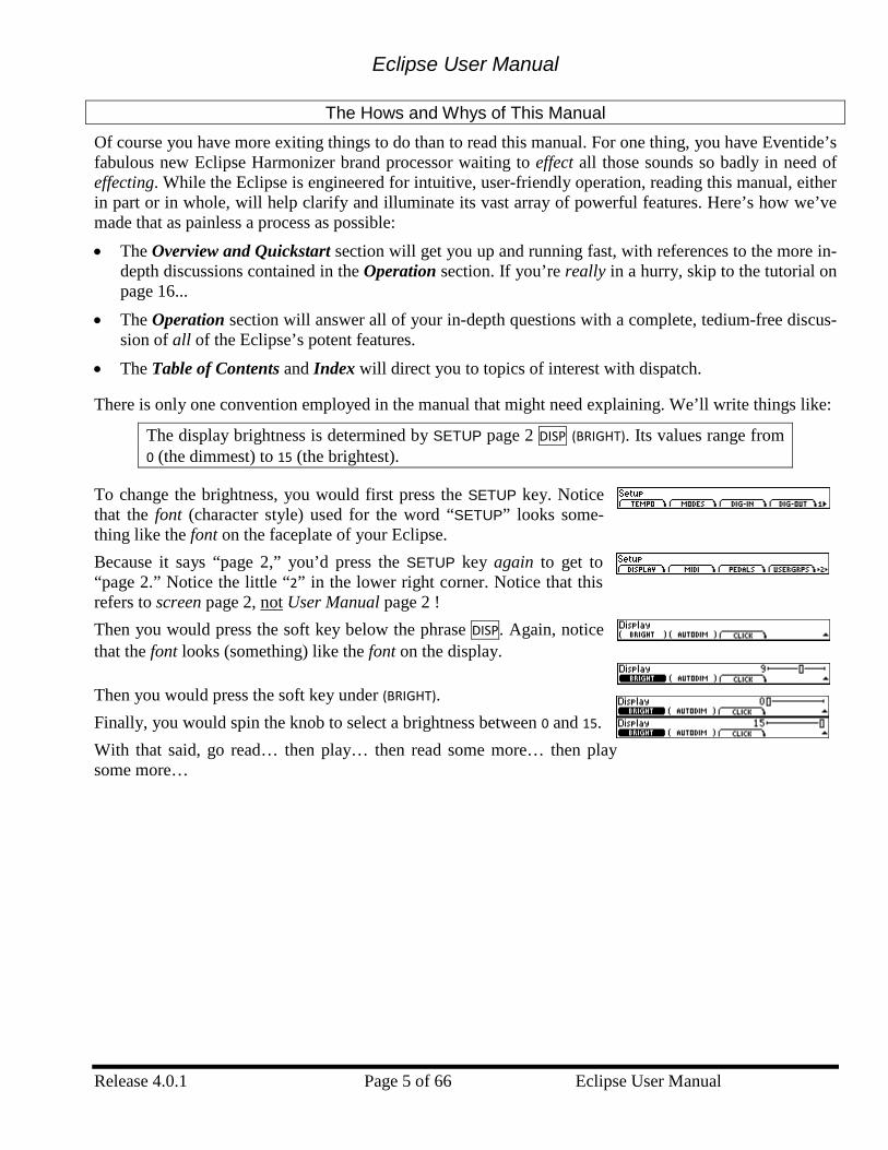
There is only one convention employed in the manual that might need explaining. We’ll write things like:
The display brightness is determined by SETUP page 2 DISP (BRIGHT). Its values range from 0 (the dimmest) to 15 (the brightest).
To change the brightness, you would first press the SETUP key. Notice that the font (character style) used for the word “SETUP” looks some-thing like the font on the faceplate of your Eclipse. Because it says “page 2,” you’d press the SETUP key again to get to “page 2.” Notice the little “2” in the lower right corner. Notice that this refers to screen page 2, not User Manual page 2 ! Then you would press the soft key below the phrase DISP. Again, notice that the font looks (something) like the font on the display.
Then you would press the soft key under (BRIGHT). Finally, you would spin the knob to select a brightness between 0 and 15. With that said, go read… then play… then read some more… then play some more…
Eclipse User Manual
Eclipse User Manual Page 6 of 66 Release 4.0.1
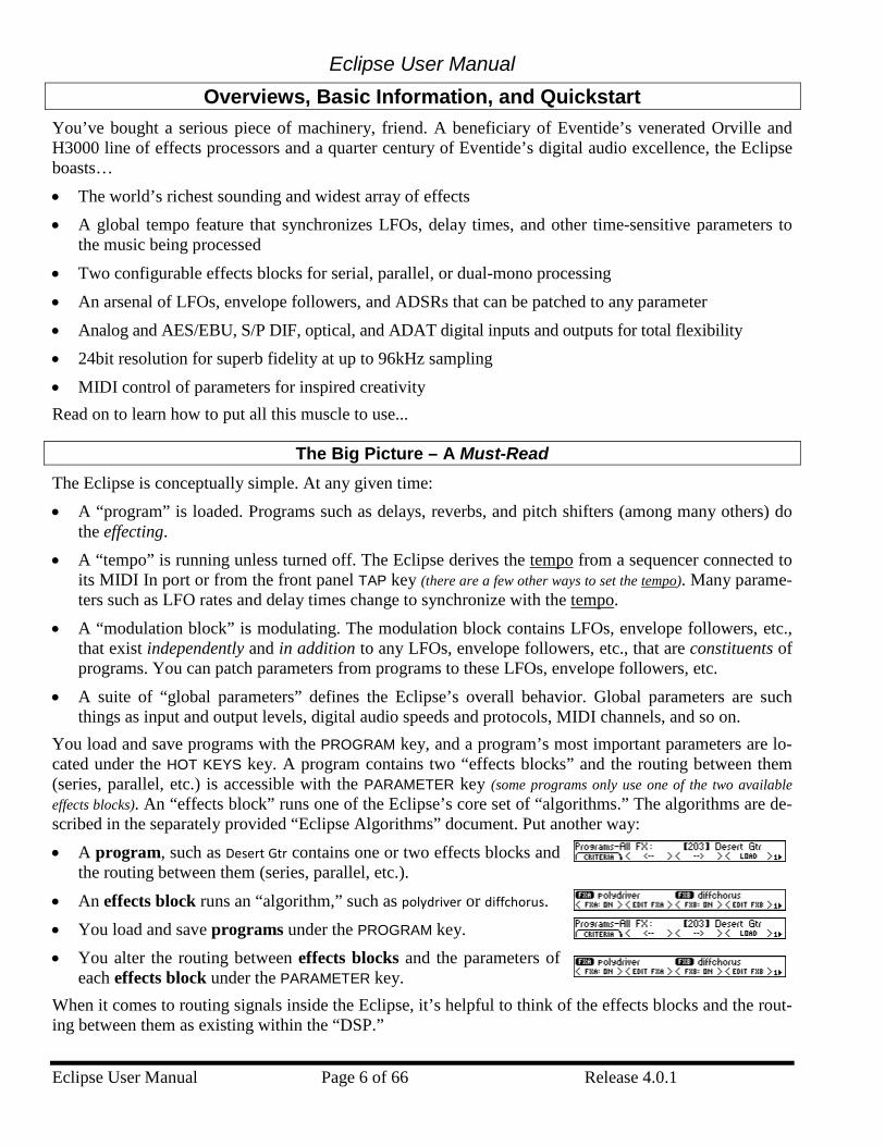
Overviews, Basic Information, and Quickstart You’ve bought a serious piece of machinery, friend. A beneficiary of Eventide’s venerated Orville and H3000 line of effects processors and a quarter century of Eventide’s digital audio excellence, the Eclipse boasts… • The world’s richest sounding and widest array of effects • A global tempo feature that synchronizes LFOs, delay times, and other time-sensitive parameters to
the music being processed • Two configurable effects blocks for serial, parallel, or dual-mono processing • An arsenal of LFOs, envelope followers, and ADSRs that can be patched to any parameter • Analog and AES/EBU, S/P DIF, optical, and ADAT digital inputs and outputs for total flexibility • 24bit resolution for superb fidelity at up to 96kHz sampling • MIDI control of parameters for inspired creativity Read on to learn how to put all this muscle to use...
The Big Picture – A Must-Read The Eclipse is conceptually simple. At any given time: • A “program” is loaded. Programs such as delays, reverbs, and pitch shifters (among many others) do
the effecting. • A “tempo” is running unless turned off. The Eclipse derives the tempo from a sequencer connected to
its MIDI In port or from the front panel TAP key (there are a few other ways to set the tempo). Many parame-ters such as LFO rates and delay times change to synchronize with the tempo.
• A “modulation block” is modulating. The modulation block contains LFOs, envelope followers, etc., that exist independently and in addition to any LFOs, envelope followers, etc., that are constituents of programs. You can patch parameters from programs to these LFOs, envelope followers, etc.
• A suite of “global parameters” defines the Eclipse’s overall behavior. Global parameters are such things as input and output levels, digital audio speeds and protocols, MIDI channels, and so on.
You load and save programs with the PROGRAM key, and a program’s most important parameters are lo-cated under the HOT KEYS key. A program contains two “effects blocks” and the routing between them (series, parallel, etc.) is accessible with the PARAMETER key (some programs only use one of the two available effects blocks). An “effects block” runs one of the Eclipse’s core set of “algorithms.” The algorithms are de-scribed in the separately provided “Eclipse Algorithms” document. Put another way: • A program, such as Desert Gtr contains one or two effects blocks and
the routing between them (series, parallel, etc.). • An effects block runs an “algorithm,” such as polydriver or diffchorus. • You load and save programs under the PROGRAM key. • You alter the routing between effects blocks and the parameters of
each effects block under the PARAMETER key. When it comes to routing signals inside the Eclipse, it’s helpful to think of the effects blocks and the rout-ing between them as existing within the “DSP.”
Eclipse User Manual
Release 4.0.1 Page 7 of 66 Eclipse User Manual
• All of the levels and signal selection outside the DSP are addressed in the LEVELS area and the SETUP area. Refer to the “Eclipse System Signal Flow” file provided on electronic disk supplied with unit to “look” at the signal flow outside the DSP. You cannot save these settings as parts of programs.
• All of the routing and levels inside the DSP are addressed in the PARAMETER area. Refer to the “Pro-gram Signal Flow” file provided on electronic disk supplied with unit to “look” at the signal flow in-side the DSP. All of these settings are saved as parts of programs.
This is as confusing as it gets, so if you have this straight you’re all set.
Knobs, Keys, and Jacks ... certified ergonomically sound after extensive testing on free-range humans.
The Front Panel
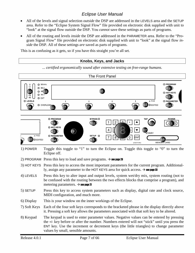
1) POWER Toggle this toggle to “1” to turn the Eclipse on. Toggle this toggle to “0” to turn the
Eclipse off. 2) PROGRAM Press this key to load and save programs. see page 28
3) HOT KEYS Press this key to access the most important parameters for the current program. Additional-ly, assign any parameter to the HOT KEYS area for quick access. see page 33
4) LEVELS Press this key to alter input and output levels, system wet/dry mix, system routing (not to be confused with the routing between the two effects blocks that comprise a program), and metering parameters. see page 21
5) SETUP Press this key to access system parameters such as display, digital rate and clock source, MIDI configuration, and much more.
6) Display This is your window on the inner workings of the Eclipse. 7) Soft Keys Each of the four soft keys corresponds to the bracketed phrase in the display directly above
it. Pressing a soft key allows the parameters associated with that soft key to be altered. 8) Keypad The keypad is used to enter parameter values. Negative values can be entered by pressing
the +/- key before or after the number. Numbers entered will not “stick” until you press the ENT key. Use the increment or decrement keys (the little triangles) to change parameter values by small, sensible amounts.
Eclipse User Manual
Eclipse User Manual Page 8 of 66 Release 4.0.1
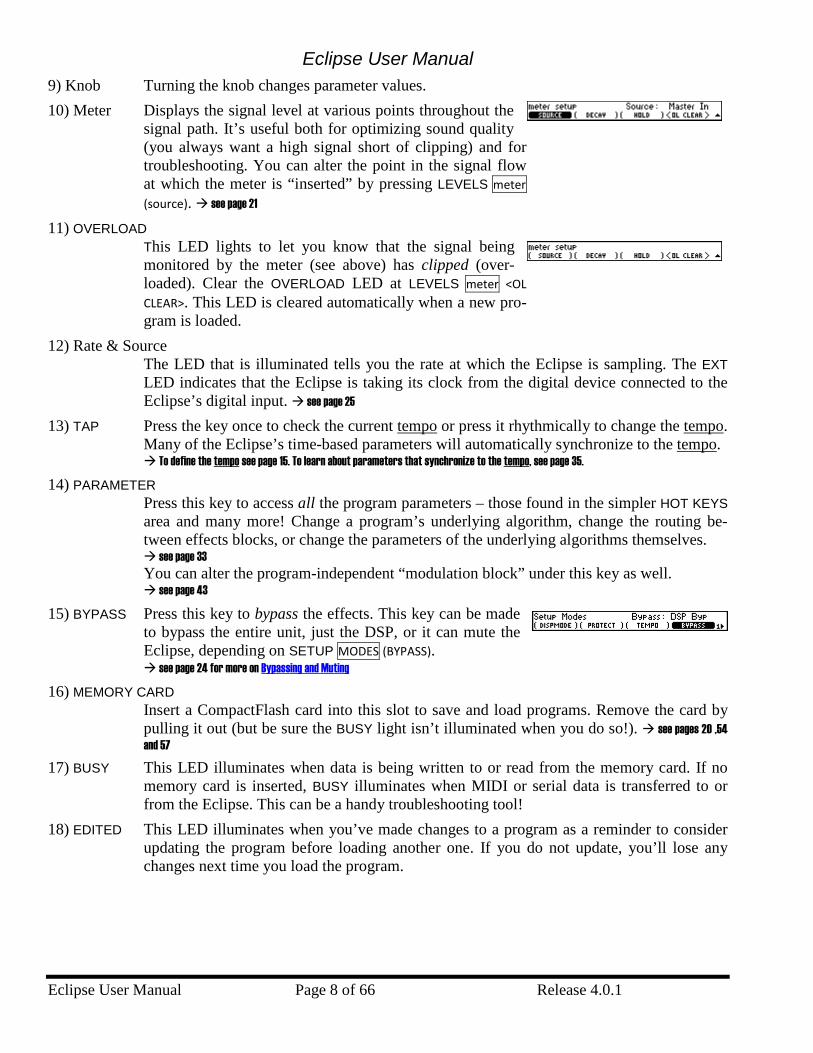
9) Knob Turning the knob changes parameter values. 10) Meter Displays the signal level at various points throughout the
signal path. It’s useful both for optimizing sound quality (you always want a high signal short of clipping) and for troubleshooting. You can alter the point in the signal flow at which the meter is “inserted” by pressing LEVELS meter (source). see page 21
11) OVERLOAD This LED lights to let you know that the signal being monitored by the meter (see above) has clipped (over-loaded). Clear the OVERLOAD LED at LEVELS meter <OL CLEAR>. This LED is cleared automatically when a new pro-gram is loaded.
12) Rate & Source The LED that is illuminated tells you the rate at which the Eclipse is sampling. The EXT LED indicates that the Eclipse is taking its clock from the digital device connected to the Eclipse’s digital input. see page 25
13) TAP Press the key once to check the current tempo or press it rhythmically to change the tempo. Many of the Eclipse’s time-based parameters will automatically synchronize to the tempo. To define the tempo see page 15. To learn about parameters that synchronize to the tempo, see page 35.
14) PARAMETER Press this key to access all the program parameters – those found in the simpler HOT KEYS area and many more! Change a program’s underlying algorithm, change the routing be-tween effects blocks, or change the parameters of the underlying algorithms themselves. see page 33 You can alter the program-independent “modulation block” under this key as well. see page 43
15) BYPASS Press this key to bypass the effects. This key can be made to bypass the entire unit, just the DSP, or it can mute the Eclipse, depending on SETUP MODES (BYPASS). see page 24 for more on Bypassing and Muting
16) MEMORY CARD Insert a CompactFlash card into this slot to save and load programs. Remove the card by pulling it out (but be sure the BUSY light isn’t illuminated when you do so!). see pages 20 ,54 and 57
17) BUSY This LED illuminates when data is being written to or read from the memory card. If no memory card is inserted, BUSY illuminates when MIDI or serial data is transferred to or from the Eclipse. This can be a handy troubleshooting tool!
18) EDITED This LED illuminates when you’ve made changes to a program as a reminder to consider updating the program before loading another one. If you do not update, you’ll lose any changes next time you load the program.
Eclipse User Manual
Release 4.0.1 Page 9 of 66 Eclipse User Manual
3
21
The Back Panel
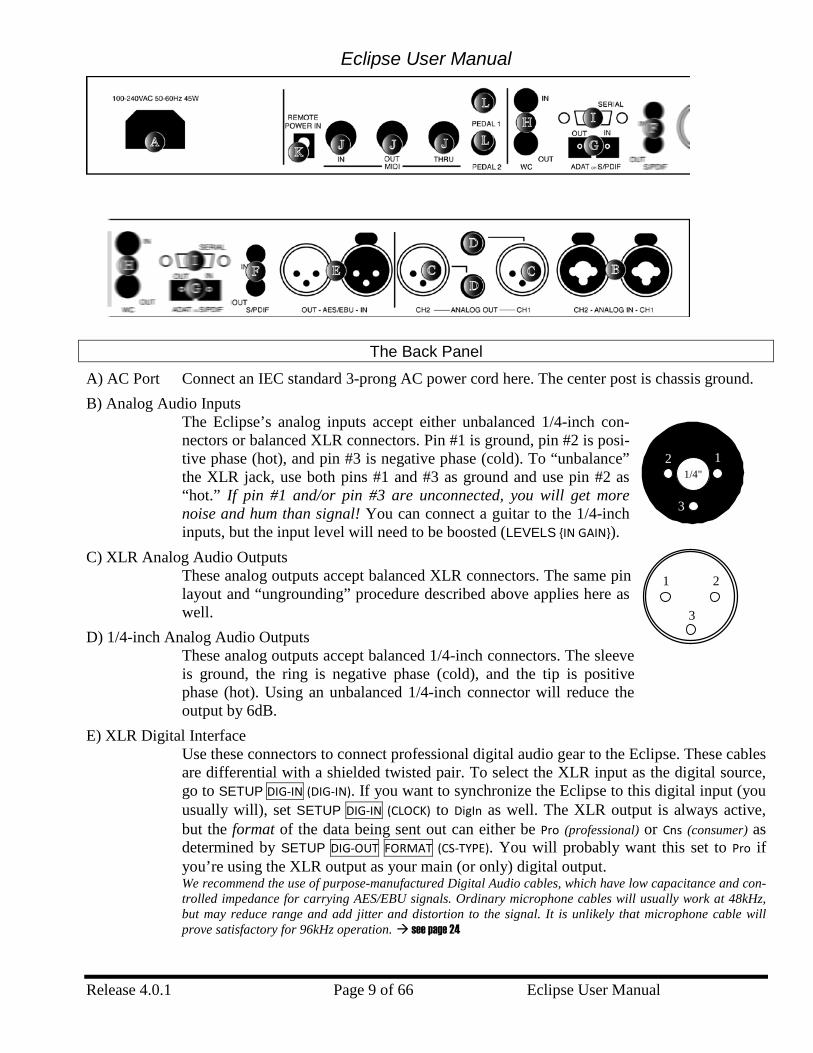
A) AC Port Connect an IEC standard 3-prong AC power cord here. The center post is chassis ground. B) Analog Audio Inputs
The Eclipse’s analog inputs accept either unbalanced 1/4-inch con-nectors or balanced XLR connectors. Pin #1 is ground, pin #2 is posi-tive phase (hot), and pin #3 is negative phase (cold). To “unbalance” the XLR jack, use both pins #1 and #3 as ground and use pin #2 as “hot.” If pin #1 and/or pin #3 are unconnected, you will get more noise and hum than signal! You can connect a guitar to the 1/4-inch inputs, but the input level will need to be boosted (LEVELS {IN GAIN}).
C) XLR Analog Audio Outputs These analog outputs accept balanced XLR connectors. The same pin layout and “ungrounding” procedure described above applies here as well.
D) 1/4-inch Analog Audio Outputs These analog outputs accept balanced 1/4-inch connectors. The sleeve is ground, the ring is negative phase (cold), and the tip is positive phase (hot). Using an unbalanced 1/4-inch connector will reduce the output by 6dB.
E) XLR Digital Interface Use these connectors to connect professional digital audio gear to the Eclipse. These cables are differential with a shielded twisted pair. To select the XLR input as the digital source, go to SETUP DIG-IN (DIG-IN). If you want to synchronize the Eclipse to this digital input (you usually will), set SETUP DIG-IN (CLOCK) to DigIn as well. The XLR output is always active, but the format of the data being sent out can either be Pro (professional) or Cns (consumer) as determined by SETUP DIG-OUT FORMAT (CS-TYPE). You will probably want this set to Pro if you’re using the XLR output as your main (or only) digital output. We recommend the use of purpose-manufactured Digital Audio cables, which have low capacitance and con-trolled impedance for carrying AES/EBU signals. Ordinary microphone cables will usually work at 48kHz, but may reduce range and add jitter and distortion to the signal. It is unlikely that microphone cable will prove satisfactory for 96kHz operation. see page 24
3
2 11/4"
Eclipse User Manual
Eclipse User Manual Page 10 of 66 Release 4.0.1
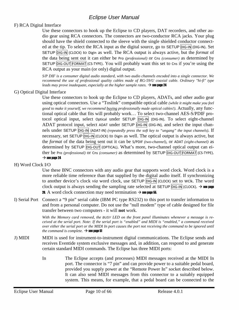
F) RCA Digital Interface Use these connectors to hook up the Eclipse to CD players, DAT recorders, and other au-dio gear using RCA connectors. The connectors are two-conductor RCA jacks. Your plug should have the shield connected to the sleeve with the single shielded conductor connect-ed at the tip. To select the RCA input as the digital source, go to SETUP DIG-IN (DIG-IN). Set SETUP DIG-IN (CLOCK) to DigIn as well. The RCA output is always active, but the format of the data being sent out it can either be Pro (professional) or Cns (consumer) as determined by SETUP DIG-OUT FORMAT (CS-TYPE). You will probably want this set to Cns if you’re using the RCA output as your main (or only) digital output. S/P DIF is a consumer digital audio standard, with two audio channels encoded into a single connector. We recommend the use of professional quality cables made of RG-59/U coaxial cable. Ordinary "hi-fi" type leads may prove inadequate, especially at the higher sample rates. see page 24
G) Optical Digital Interface Use these connectors to hook up the Eclipse to CD players, ADATs, and other audio gear using optical connectors. Use a “Toslink” compatible optical cable (while it might make you feel good to make it yourself, we recommend buying professionally made optical cables!). Actually, any func-tional optical cable that fits will probably work… To select two-channel AES-S/PDIF pro-tocol optical input, select Optical under SETUP DIG-IN (DIG-IN). To select eight-channel ADAT protocol input, select ADAT under SETUP DIG-IN (DIG-IN), and select the input chan-nels under SETUP DIG-IN {ADAT-IN} (repeatedly press the soft key to “ungang” the input channels). If necessary, set SETUP DIG-IN (CLOCK) to DigIn as well. The optical output is always active, but the format of the data being sent out it can be S/PDIF (two-channel), or ADAT (eight-channel) as determined by SETUP DIG-OUT (OPTICAL). What’s more, two-channel optical output can ei-ther be Pro (professional) or Cns (consumer) as determined by SETUP DIG-OUT FORMAT (CS-TYPE). see page 24
H) Word Clock I/O Use these BNC connectors with any audio gear that supports word clock. Word clock is a more reliable time reference than that supplied by the digital audio itself. If synchronizing to another device’s clock via word clock, use SETUP DIG-IN (CLOCK) set to WClk. The word clock output is always sending the sampling rate selected at SETUP DIG-IN (CLOCK). see page 26. A word clock connection may need termination see page 55.
I) Serial Port Connect a “9 pin” serial cable (IBM PC type RS232) to this port to transfer information to and from a personal computer. Do not use the "null modem" type of cable designed for file transfer between two computers - it will not work. With the Memory card removed, the BUSY LED on the front panel illuminates whenever a message is re-ceived at the serial port. Note: If the serial port is “enabled” and MIDI is “enabled,” a command received over either the serial port or the MIDI In port causes the port not receiving the command to be ignored until the command is complete. see page 51
J) MIDI MIDI is used for instrument-to-instrument digital communications. The Eclipse sends and receives Eventide system exclusive messages and, in addition, can respond to and generate certain standard MIDI commands. The Eclipse has three MIDI ports:
In The Eclipse accepts (and processes) MIDI messages received at the MIDI In port. The connector is “7 pin” and can provide power to a suitable pedal board, provided you supply power at the “Remote Power In” socket described below. It can also send MIDI messages from this connector to a suitably equipped system. This means, for example, that a pedal board can be connected to the
Eclipse User Manual
Release 4.0.1 Page 11 of 66 Eclipse User Manual
Eclipse by means of a single cable that supplies power as well as a communi-cation path. A normal “5 pin” MIDI cable can be used as a standard MIDI in-put.
Out The Eclipse sends MIDI messages to other devices via the Out port. MIDI mes-sages are also sent out the serial port if it is “enabled.”
Thru Any MIDI information received at the MIDI In port is echoed directly to the MIDI Thru port regardless of the Eclipse’s configuration (as long as the Eclipse is powered up). With the Memory card removed, the BUSY LED on the front panel illuminates whenever a MIDI message is received at the MIDI In port. Note: If the serial port is “enabled” and MIDI is “enabled,” a command received over either the serial port or the MIDI In port causes the port not receiving the command to be ignored until the command is complete. for MIDI Setup, see page 48
K) Remote Power In Power supplied at this jack is sent “down” the MIDI In port’s pins 6 and 7. Use a suitable MIDI pedal board and connect its “wall wart” (external power supply) to this jack. Use a "7 pin" MIDI cable between the Out port on the board and the In port on the Eclipse. Pow-er will be remotely supplied to the MIDI pedal board.
L) Foot Pedal Jacks 1 & 2 Stereo 1/4-inch connectors. The sleeve is ground reference, the ring is a +5 volt (source), and the tip is an analog signal between 0 to 5 volts input to the Eclipse. Connect either foot switches, foot pedals, or control voltage sources to these inputs to modulate parameters or to trigger events (including remote program loads, see page 48). To set up the foot pedal jacks, see page 49
Getting Around and Altering Parameters At any given time, the Eclipse is doing a whole bunch of “stuff.” Unfortunately, you can’t look at all that “stuff” in one fell swoop. We could have arranged things otherwise, but we figured you’d rather not devote twelve rack spaces to the Eclipse display where you really only need one! As a compromise, we’ve created a number of “win-dows” on its inner-workings. We call them “areas.” Inside each area are parameters that can be selected by using the “soft keys” below the display. Once a parameter is selected, you can alter its value with the knob or the keypad. Let’s look at this in a little more depth, shall we?
The “Areas” (e.g. – Levels, Program, Setup, etc.)
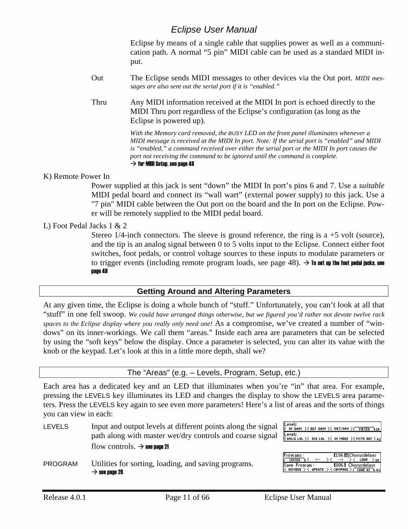
Each area has a dedicated key and an LED that illuminates when you’re “in” that area. For example, pressing the LEVELS key illuminates its LED and changes the display to show the LEVELS area parame-ters. Press the LEVELS key again to see even more parameters! Here’s a list of areas and the sorts of things you can view in each: LEVELS Input and output levels at different points along the signal
path along with master wet/dry controls and coarse signal flow controls. see page 21
PROGRAM Utilities for sorting, loading, and saving programs. see page 28
Eclipse User Manual
Eclipse User Manual Page 12 of 66 Release 4.0.1
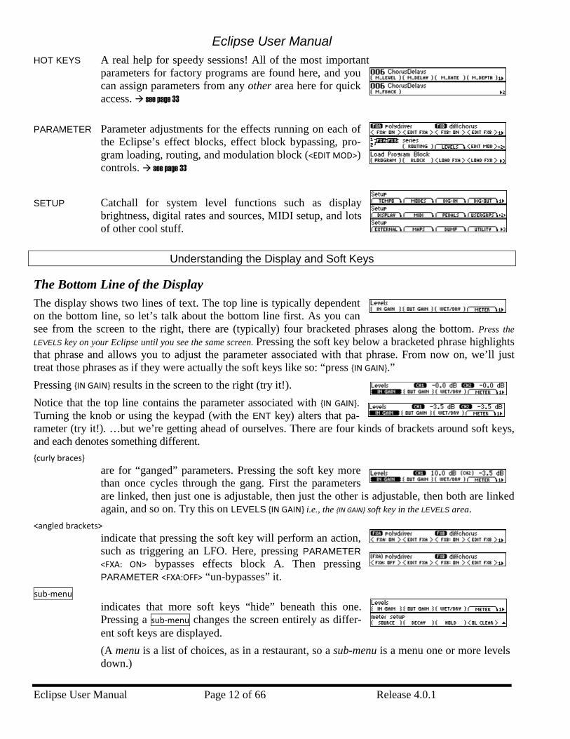
HOT KEYS A real help for speedy sessions! All of the most important parameters for factory programs are found here, and you can assign parameters from any other area here for quick access. see page 33
PARAMETER Parameter adjustments for the effects running on each of
the Eclipse’s effect blocks, effect block bypassing, pro-gram loading, routing, and modulation block (<EDIT MOD>) controls. see page 33
SETUP Catchall for system level functions such as display
brightness, digital rates and sources, MIDI setup, and lots of other cool stuff.
Understanding the Display and Soft Keys
The Bottom Line of the Display The display shows two lines of text. The top line is typically dependent on the bottom line, so let’s talk about the bottom line first. As you can see from the screen to the right, there are (typically) four bracketed phrases along the bottom. Press the LEVELS key on your Eclipse until you see the same screen. Pressing the soft key below a bracketed phrase highlights that phrase and allows you to adjust the parameter associated with that phrase. From now on, we’ll just treat those phrases as if they were actually the soft keys like so: “press {IN GAIN}.” Pressing {IN GAIN} results in the screen to the right (try it!). Notice that the top line contains the parameter associated with {IN GAIN}. Turning the knob or using the keypad (with the ENT key) alters that pa-rameter (try it!). …but we’re getting ahead of ourselves. There are four kinds of brackets around soft keys, and each denotes something different. {curly braces}
are for “ganged” parameters. Pressing the soft key more than once cycles through the gang. First the parameters are linked, then just one is adjustable, then just the other is adjustable, then both are linked again, and so on. Try this on LEVELS {IN GAIN} i.e., the {IN GAIN} soft key in the LEVELS area.
<angled brackets> indicate that pressing the soft key will perform an action, such as triggering an LFO. Here, pressing PARAMETER <FXA: ON> bypasses effects block A. Then pressing PARAMETER <FXA:OFF> “un-bypasses” it.
sub-menu indicates that more soft keys “hide” beneath this one. Pressing a sub-menu changes the screen entirely as differ-ent soft keys are displayed. (A menu is a list of choices, as in a restaurant, so a sub-menu is a menu one or more levels down.)
Eclipse User Manual
Release 4.0.1 Page 13 of 66 Eclipse User Manual
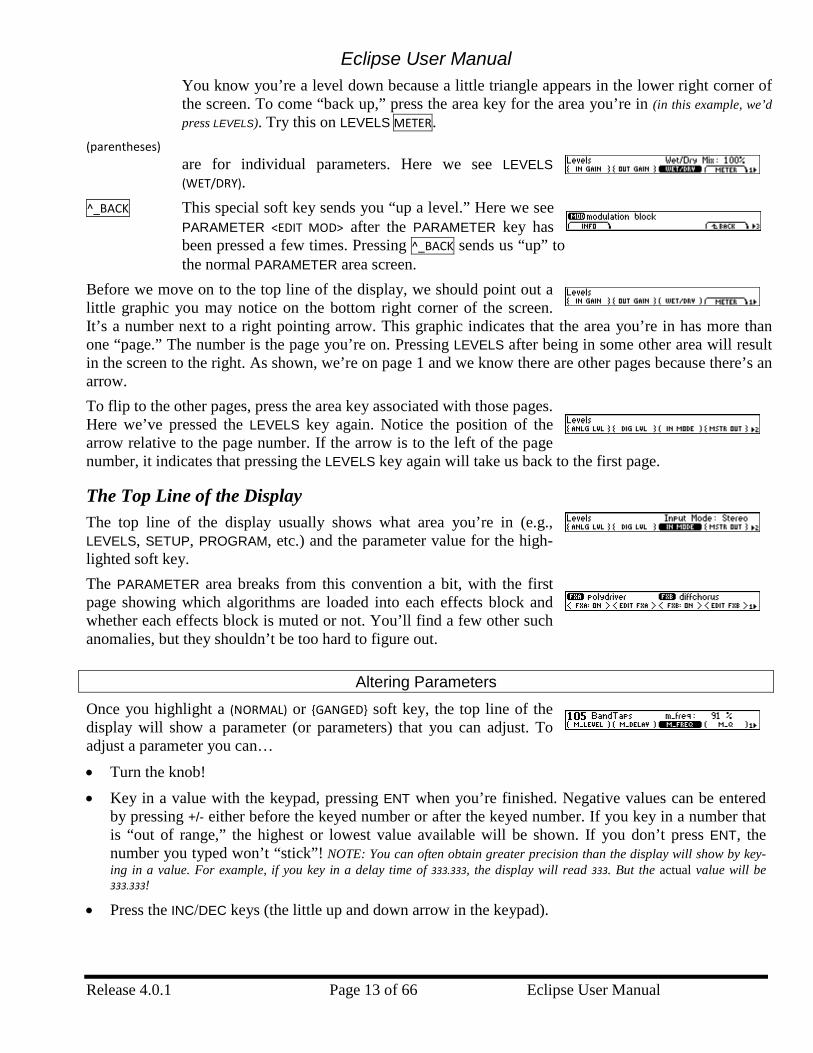
You know you’re a level down because a little triangle appears in the lower right corner of the screen. To come “back up,” press the area key for the area you’re in (in this example, we’d press LEVELS). Try this on LEVELS METER.
(parentheses) are for individual parameters. Here we see LEVELS (WET/DRY).
^_BACK This special soft key sends you “up a level.” Here we see PARAMETER <EDIT MOD> after the PARAMETER key has been pressed a few times. Pressing ^_BACK sends us “up” to the normal PARAMETER area screen.
Before we move on to the top line of the display, we should point out a little graphic you may notice on the bottom right corner of the screen. It’s a number next to a right pointing arrow. This graphic indicates that the area you’re in has more than one “page.” The number is the page you’re on. Pressing LEVELS after being in some other area will result in the screen to the right. As shown, we’re on page 1 and we know there are other pages because there’s an arrow. To flip to the other pages, press the area key associated with those pages. Here we’ve pressed the LEVELS key again. Notice the position of the arrow relative to the page number. If the arrow is to the left of the page number, it indicates that pressing the LEVELS key again will take us back to the first page.
The Top Line of the Display The top line of the display usually shows what area you’re in (e.g., LEVELS, SETUP, PROGRAM, etc.) and the parameter value for the high-lighted soft key. The PARAMETER area breaks from this convention a bit, with the first page showing which algorithms are loaded into each effects block and whether each effects block is muted or not. You’ll find a few other such anomalies, but they shouldn’t be too hard to figure out.
Altering Parameters
Once you highlight a (NORMAL) or {GANGED} soft key, the top line of the display will show a parameter (or parameters) that you can adjust. To adjust a parameter you can… • Turn the knob! • Key in a value with the keypad, pressing ENT when you’re finished. Negative values can be entered
by pressing +/- either before the keyed number or after the keyed number. If you key in a number that is “out of range,” the highest or lowest value available will be shown. If you don’t press ENT, the number you typed won’t “stick”! NOTE: You can often obtain greater precision than the display will show by key-ing in a value. For example, if you key in a delay time of 333.333, the display will read 333. But the actual value will be 333.333!
• Press the INC/DEC keys (the little up and down arrow in the keypad).
Eclipse User Manual
Eclipse User Manual Page 14 of 66 Release 4.0.1
Quickstart Pressing keys is fine, but if that’s all you wanted to do you’d have been better off buying an infant’s “ac-tivity center”. No, the whole point is to get some of that Eventide goodness into your music, and that’s just what we’re gonna do now…
Hooking Up To the Outside World
The Eclipse will sum analog and digital inputs and will output both analog and digital signals at all times. see the separate “Eclipse System Signal Flow” sheet for all the gory details
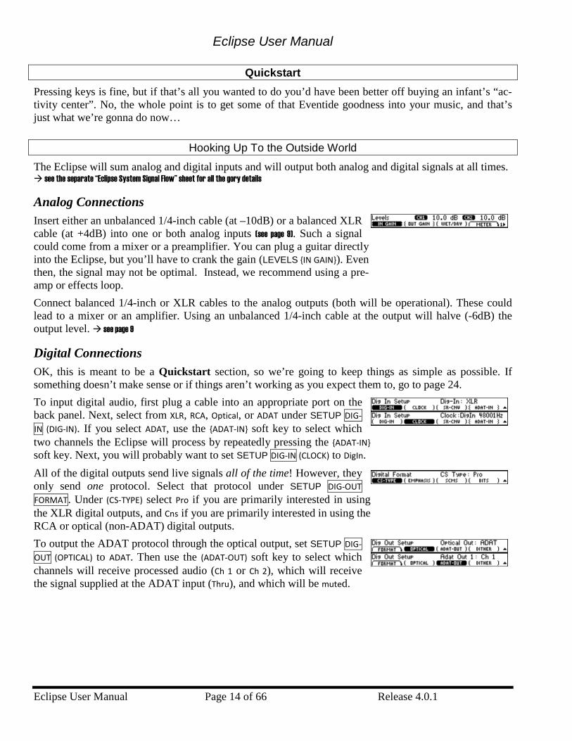
Analog Connections Insert either an unbalanced 1/4-inch cable (at –10dB) or a balanced XLR cable (at +4dB) into one or both analog inputs (see page 9). Such a signal could come from a mixer or a preamplifier. You can plug a guitar directly into the Eclipse, but you’ll have to crank the gain (LEVELS {IN GAIN}). Even then, the signal may not be optimal. Instead, we recommend using a pre-amp or effects loop. Connect balanced 1/4-inch or XLR cables to the analog outputs (both will be operational). These could lead to a mixer or an amplifier. Using an unbalanced 1/4-inch cable at the output will halve (-6dB) the output level. see page 9
Digital Connections OK, this is meant to be a Quickstart section, so we’re going to keep things as simple as possible. If something doesn’t make sense or if things aren’t working as you expect them to, go to page 24. To input digital audio, first plug a cable into an appropriate port on the back panel. Next, select from XLR, RCA, Optical, or ADAT under SETUP DIG-IN (DIG-IN). If you select ADAT, use the {ADAT-IN} soft key to select which two channels the Eclipse will process by repeatedly pressing the {ADAT-IN} soft key. Next, you will probably want to set SETUP DIG-IN (CLOCK) to DigIn. All of the digital outputs send live signals all of the time! However, they only send one protocol. Select that protocol under SETUP DIG-OUT FORMAT. Under (CS-TYPE) select Pro if you are primarily interested in using the XLR digital outputs, and Cns if you are primarily interested in using the RCA or optical (non-ADAT) digital outputs. To output the ADAT protocol through the optical output, set SETUP DIG-OUT (OPTICAL) to ADAT. Then use the (ADAT-OUT) soft key to select which channels will receive processed audio (Ch 1 or Ch 2), which will receive the signal supplied at the ADAT input (Thru), and which will be muted.
Eclipse User Manual
Release 4.0.1 Page 15 of 66 Eclipse User Manual
Choosing Effects
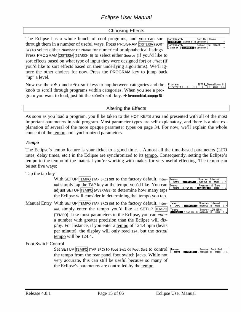
The Eclipse has a whole bunch of cool programs, and you can sort through them in a number of useful ways. Press PROGRAM CRITERIA (SORT BY) to select either Number or Name for numerical or alphabetical listings. Press PROGRAM CRITERIA (SEARCH B) to select either Source (if you’d like to sort effects based on what type of input they were designed for) or Effect (if you’d like to sort effects based on their underlying algorithms). We’ll ig-nore the other choices for now. Press the PROGRAM key to jump back “up” a level. Now use the < > and < > soft keys to hop between categories and the knob to scroll through programs within categories. When you see a pro-gram you want to load, just hit the <LOAD> soft key. for more detail, see page 28
Altering the Effects
As soon as you load a program, you’ll be taken to the HOT KEYS area and presented with all of the most important parameters in said program. Most parameter types are self-explanatory, and there is a nice ex-planation of several of the more opaque parameter types on page 34. For now, we’ll explain the whole concept of the tempo and synchronized parameters.
Tempo The Eclipse’s tempo feature is your ticket to a good time… Almost all the time-based parameters (LFO rates, delay times, etc.) in the Eclipse are synchronized to its tempo. Consequently, setting the Eclipse’s tempo to the tempo of the material you’re working with makes for very useful effecting. The tempo can be set five ways: Tap the tap key
With SETUP TEMPO (TAP SRC) set to the factory default, Inter-nal, simply tap the TAP key at the tempo you’d like. You can adjust SETUP TEMPO (AVERAGE) to determine how many taps the Eclipse will consider in determining the tempo you tap.
Manual Entry With SETUP TEMPO (TAP SRC) set to the factory default, Inter-nal, simply enter the tempo you’d like at SETUP TEMPO
(TEMPO). Like most parameters in the Eclipse, you can enter a number with greater precision than the Eclipse will dis-play. For instance, if you enter a tempo of 124.4 bpm (beats per minute), the display will only read 124, but the actual tempo will be 124.4.
Foot Switch Control Set SETUP TEMPO (TAP SRC) to Foot Sw1 or Foot Sw2 to control the tempo from the rear panel foot switch jacks. While not very accurate, this can still be useful because so many of the Eclipse’s parameters are controlled by the tempo.
Eclipse User Manual
Eclipse User Manual Page 16 of 66 Release 4.0.1
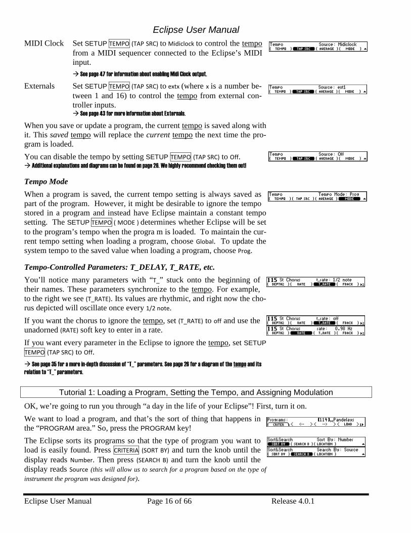
MIDI Clock Set SETUP TEMPO (TAP SRC) to Midiclock to control the tempo from a MIDI sequencer connected to the Eclipse’s MIDI input. See page 47 for information about enabling Midi Clock output.
Externals Set SETUP TEMPO (TAP SRC) to extx (where x is a number be-tween 1 and 16) to control the tempo from external con-troller inputs. See page 43 for more information about Externals.
When you save or update a program, the current tempo is saved along with it. This saved tempo will replace the current tempo the next time the pro-gram is loaded. You can disable the tempo by setting SETUP TEMPO (TAP SRC) to Off. Additional explanations and diagrams can be found on page 26. We highly recommend checking them out!
Tempo Mode When a program is saved, the current tempo setting is always saved as part of the program. However, it might be desirable to ignore the tempo stored in a program and instead have Eclipse maintain a constant tempo setting. The SETUP TEMPO ( MODE ) determines whether Eclipse will be set to the program’s tempo when the progra m is loaded. To maintain the cur-rent tempo setting when loading a program, choose Global. To update the system tempo to the saved value when loading a program, choose Prog.
Tempo-Controlled Parameters: T_DELAY, T_RATE, etc. You’ll notice many parameters with “T_” stuck onto the beginning of their names. These parameters synchronize to the tempo. For example, to the right we see (T_RATE). Its values are rhythmic, and right now the cho-rus depicted will oscillate once every 1/2 note. If you want the chorus to ignore the tempo, set (T_RATE) to off and use the unadorned (RATE) soft key to enter in a rate. If you want every parameter in the Eclipse to ignore the tempo, set SETUP TEMPO (TAP SRC) to Off. See page 35 for a more in-depth discussion of “T_” parameters. See page 26 for a diagram of the tempo and its relation to “T_” parameters.
Tutorial 1: Loading a Program, Setting the Tempo, and Assigning Modulation
OK, we’re going to run you through “a day in the life of your Eclipse”! First, turn it on. We want to load a program, and that’s the sort of thing that happens in the “PROGRAM area.” So, press the PROGRAM key! The Eclipse sorts its programs so that the type of program you want to load is easily found. Press CRITERIA (SORT BY) and turn the knob until the display reads Number. Then press (SEARCH B) and turn the knob until the display reads Source (this will allow us to search for a program based on the type of instrument the program was designed for).
Eclipse User Manual
Release 4.0.1 Page 17 of 66 Eclipse User Manual
Press the PROGRAM key again to jump “up” a level. see page 28 for more information
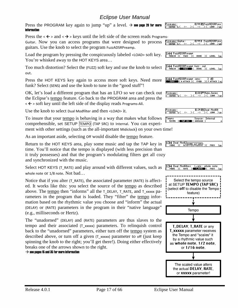
Press the < > and < > keys until the left side of the screen reads Programs-Guitar. Now you can access programs that were designed to process guitars. Use the knob to select the program FuzzADSRPreamp. Load the program by pressing the conspicuously labeled <LOAD> soft key. You’re whisked away to the HOT KEYS area… Too much distortion? Select the (FUZZ) soft key and use the knob to select out. Press the HOT KEYS key again to access more soft keys. Need more funk? Select (SENS) and use the knob to tune in the “good stuff”! OK, let’s load a different program that has an LFO so we can check out the Eclipse’s tempo feature. Go back to the PROGRAM area and press the < > soft key until the left side of the display reads Programs-All. Use the knob to select Dual Modfilter and then <LOAD> it. To insure that your tempo is behaving in a way that makes what follows comprehensible, set SETUP TEMPO (TAP SRC) to Internal. You can experi-ment with other settings (such as the all-important Midiclock) on your own time! As an important aside, selecting Off would disable the tempo feature. Return to the HOT KEYS area, play some music and tap the TAP key in time. You’ll notice that the tempo is displayed (with less precision than it truly possesses) and that the program’s modulating filters get all cozy and synchronized with the music. Select HOT KEYS (T_RATE) and play around with different values, such as whole note or 1/8 note. Not bad… Notice that if you alter (T_RATE), the associated parameter (RATE) is affect-ed. It works like this: you select the source of the tempo as described above. The tempo then “informs” all the T_DELAY, T_RATE, and T_xxxxx pa-rameters in the program that is loaded. They “filter” the tempo infor-mation based on the rhythmic value you choose and “inform” the actual (DELAY) or (RATE) parameters in the program in their “native language” (e.g., milliseconds or Hertz). The “unadorned” (DELAY) and (RATE) parameters are thus slaves to the tempo and their associated (T_xxxxx) parameters. To relinquish control back to the “unadorned” parameters, either turn off the tempo system as described above, or turn off a given (T_xxxxx) parameter to off (just keep spinning the knob to the right; you’ll get there!). Doing either effectively breaks one of the arrows shown to the right. see pages 15 and 35 for more information
Eclipse User Manual
Eclipse User Manual Page 18 of 66 Release 4.0.1
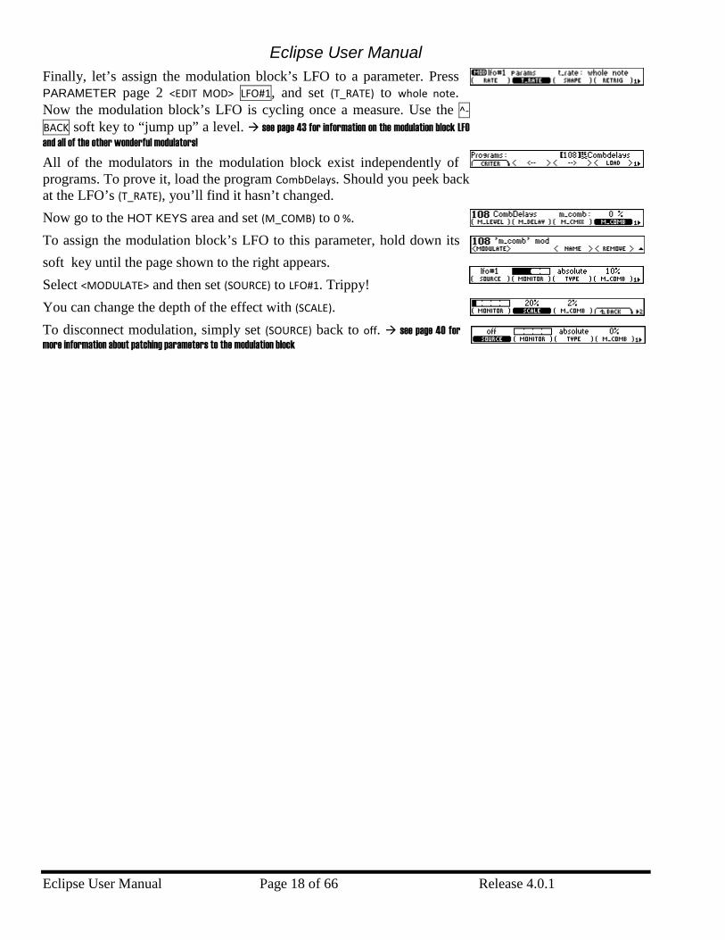
Finally, let’s assign the modulation block’s LFO to a parameter. Press PARAMETER page 2 <EDIT MOD> LFO#1, and set (T_RATE) to whole note. Now the modulation block’s LFO is cycling once a measure. Use the ^-BACK soft key to “jump up” a level. see page 43 for information on the modulation block LFO and all of the other wonderful modulators!
All of the modulators in the modulation block exist independently of programs. To prove it, load the program CombDelays. Should you peek back at the LFO’s (T_RATE), you’ll find it hasn’t changed. Now go to the HOT KEYS area and set (M_COMB) to 0 %. To assign the modulation block’s LFO to this parameter, hold down its soft key until the page shown to the right appears. Select <MODULATE> and then set (SOURCE) to LFO#1. Trippy! You can change the depth of the effect with (SCALE). To disconnect modulation, simply set (SOURCE) back to off. see page 40 for more information about patching parameters to the modulation block
Eclipse User Manual
Release 4.0.1 Page 19 of 66 Eclipse User Manual
Tutorial 2: Creating a Program “from Scratch” and Assigning a Hot Key
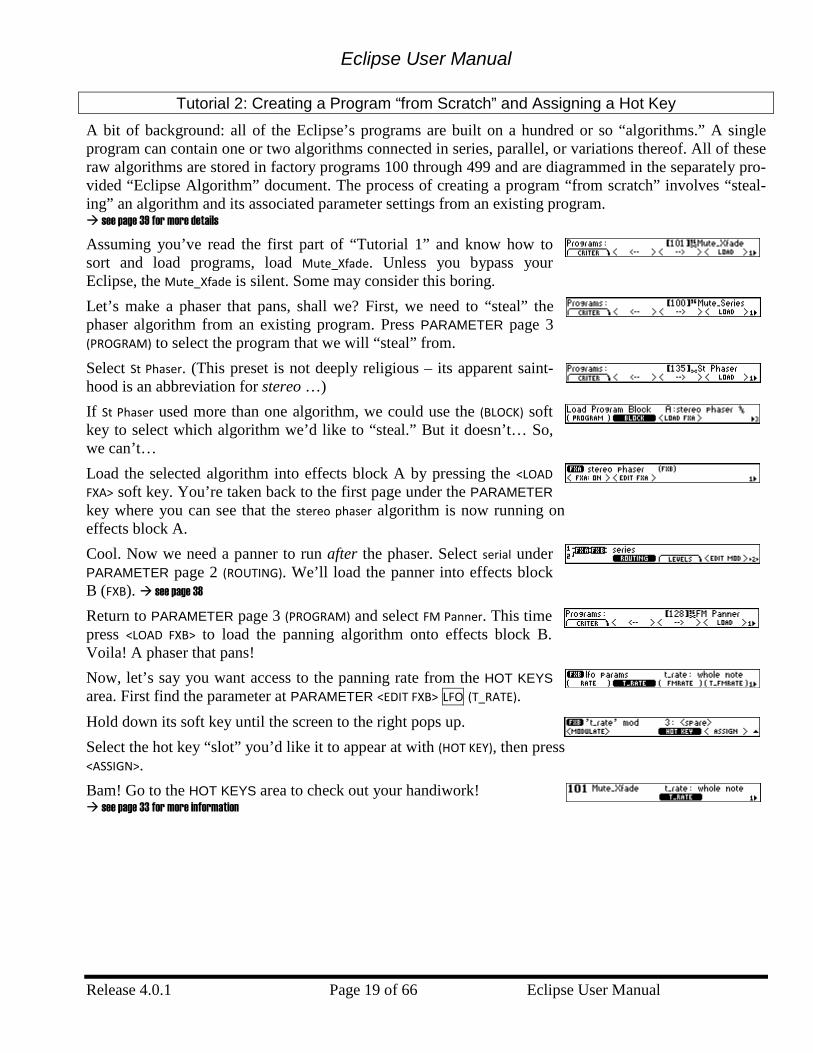
A bit of background: all of the Eclipse’s programs are built on a hundred or so “algorithms.” A single program can contain one or two algorithms connected in series, parallel, or variations thereof. All of these raw algorithms are stored in factory programs 100 through 499 and are diagrammed in the separately pro-vided “Eclipse Algorithm” document. The process of creating a program “from scratch” involves “steal-ing” an algorithm and its associated parameter settings from an existing program. see page 39 for more details Assuming you’ve read the first part of “Tutorial 1” and know how to sort and load programs, load Mute_Xfade. Unless you bypass your Eclipse, the Mute_Xfade is silent. Some may consider this boring. Let’s make a phaser that pans, shall we? First, we need to “steal” the phaser algorithm from an existing program. Press PARAMETER page 3 (PROGRAM) to select the program that we will “steal” from. Select St Phaser. (This preset is not deeply religious – its apparent saint-hood is an abbreviation for stereo …) If St Phaser used more than one algorithm, we could use the (BLOCK) soft key to select which algorithm we’d like to “steal.” But it doesn’t… So, we can’t… Load the selected algorithm into effects block A by pressing the <LOAD FXA> soft key. You’re taken back to the first page under the PARAMETER key where you can see that the stereo phaser algorithm is now running on effects block A. Cool. Now we need a panner to run after the phaser. Select serial under PARAMETER page 2 (ROUTING). We’ll load the panner into effects block B (FXB). see page 38
Return to PARAMETER page 3 (PROGRAM) and select FM Panner. This time press <LOAD FXB> to load the panning algorithm onto effects block B. Voila! A phaser that pans! Now, let’s say you want access to the panning rate from the HOT KEYS area. First find the parameter at PARAMETER <EDIT FXB> LFO (T_RATE). Hold down its soft key until the screen to the right pops up. Select the hot key “slot” you’d like it to appear at with (HOT KEY), then press <ASSIGN>. Bam! Go to the HOT KEYS area to check out your handiwork! see page 33 for more information
Eclipse User Manual
Eclipse User Manual Page 20 of 66 Release 4.0.1
Operation …don’t touch the sides! You remember “Operation” - the childhood game where you pull plastic bones and other parts out of a little cardboard man? No? Oh well…
Mounting and Handling
Normally, you should have the Eclipse rack mounted in a standard 19-inch rack. If you take it on the road, support it from the rear as well. Keep the Eclipse well ventilated, dust-free, dry, and, like Little Bear’s porridge, neither too hot nor too cold. Don’t play catch with the Eclipse or use it as a bat. Pat the Eclipse gently and whisper sweet nothings of affection in its direction before powering it down for the night…
Memory Cards
The Eclipse accepts CompactFlash cards of all memory capacities. All functions that work with internal memory also work with memory cards. In addition to increasing the number of programs you can store, memory cards allow you to take your programs to a friend’s Eclipse or to trade your programs for can-dies. To insert a memory card, well, just insert it until it stops. To remove a memory card, just pull it out (but be sure that the yellow BUSY light isn’t illuminated when you do so!). It’s possible to load a program from a memory card and then remove the memory card – the program will still run. The card only needs to be in place for such functions as loading, saving, updating, removing, and so forth. see page 54 for formatting information While more resilient than removable media of yesteryear, you should still treat your CompactFlash cards with respect, lest bad things happen. Don’t spill on them, don’t shock them, don’t leave them on the dash under hot sun, and on and on. CompactFlash cards do not need batteries.
The Display Brightness and Click Features
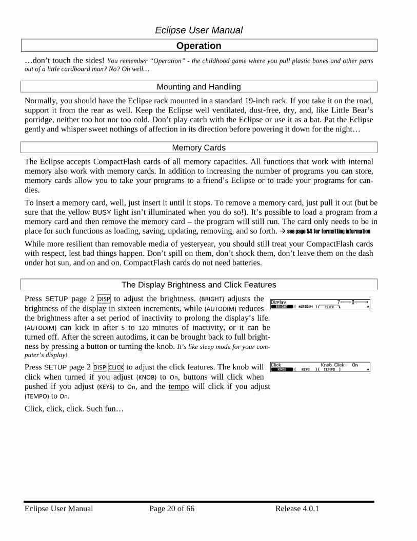
Press SETUP page 2 DISP to adjust the brightness. (BRIGHT) adjusts the brightness of the display in sixteen increments, while (AUTODIM) reduces the brightness after a set period of inactivity to prolong the display’s life. (AUTODIM) can kick in after 5 to 120 minutes of inactivity, or it can be turned off. After the screen autodims, it can be brought back to full bright-ness by pressing a button or turning the knob. It’s like sleep mode for your com-puter’s display! Press SETUP page 2 DISP CLICK to adjust the click features. The knob will click when turned if you adjust (KNOB) to On, buttons will click when pushed if you adjust (KEYS) to On, and the tempo will click if you adjust (TEMPO) to On. Click, click, click. Such fun…
Eclipse User Manual
Release 4.0.1 Page 21 of 66 Eclipse User Manual
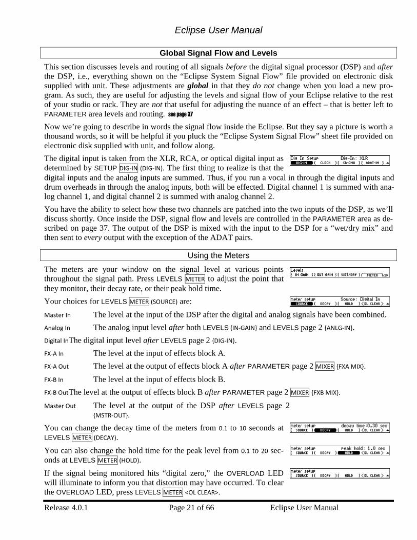
Global Signal Flow and Levels This section discusses levels and routing of all signals before the digital signal processor (DSP) and after the DSP, i.e., everything shown on the “Eclipse System Signal Flow” file provided on electronic disk supplied with unit. These adjustments are global in that they do not change when you load a new pro-gram. As such, they are useful for adjusting the levels and signal flow of your Eclipse relative to the rest of your studio or rack. They are not that useful for adjusting the nuance of an effect – that is better left to PARAMETER area levels and routing. see page 37 Now we’re going to describe in words the signal flow inside the Eclipse. But they say a picture is worth a thousand words, so it will be helpful if you pluck the “Eclipse System Signal Flow” sheet file provided on electronic disk supplied with unit, and follow along. The digital input is taken from the XLR, RCA, or optical digital input as determined by SETUP DIG-IN (DIG-IN). The first thing to realize is that the digital inputs and the analog inputs are summed. Thus, if you run a vocal in through the digital inputs and drum overheads in through the analog inputs, both will be effected. Digital channel 1 is summed with ana-log channel 1, and digital channel 2 is summed with analog channel 2. You have the ability to select how these two channels are patched into the two inputs of the DSP, as we’ll discuss shortly. Once inside the DSP, signal flow and levels are controlled in the PARAMETER area as de-scribed on page 37. The output of the DSP is mixed with the input to the DSP for a “wet/dry mix” and then sent to every output with the exception of the ADAT pairs.
Using the Meters
The meters are your window on the signal level at various points throughout the signal path. Press LEVELS METER to adjust the point that they monitor, their decay rate, or their peak hold time. Your choices for LEVELS METER (SOURCE) are: Master In The level at the input of the DSP after the digital and analog signals have been combined. Analog In The analog input level after both LEVELS {IN-GAIN} and LEVELS page 2 {ANLG-IN}. Digital In The digital input level after LEVELS page 2 {DIG-IN}. FX-A In The level at the input of effects block A. FX-A Out The level at the output of effects block A after PARAMETER page 2 MIXER {FXA MIX}. FX-B In The level at the input of effects block B. FX-B Out The level at the output of effects block B after PARAMETER page 2 MIXER {FXB MIX}. Master Out The level at the output of the DSP after LEVELS page 2
{MSTR-OUT}. You can change the decay time of the meters from 0.1 to 10 seconds at LEVELS METER (DECAY). You can also change the hold time for the peak level from 0.1 to 20 sec-onds at LEVELS METER (HOLD). If the signal being monitored hits “digital zero,” the OVERLOAD LED will illuminate to inform you that distortion may have occurred. To clear the OVERLOAD LED, press LEVELS METER <OL CLEAR>.
Eclipse User Manual
Eclipse User Manual Page 22 of 66 Release 4.0.1
Input and Output Modes (Global Stereo or Global Mono?)
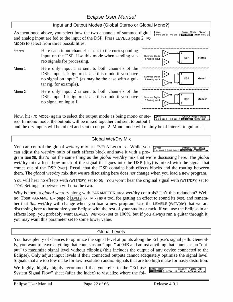
As mentioned above, you select how the two channels of summed digital and analog input are fed to the input of the DSP. Press LEVELS page 2 (I/O MODE) to select from three possibilities. Stereo Here each input channel is sent to the corresponding
input on the DSP. Use this mode when sending ste-reo signals for processing.
Mono 1 Here only input 1 is sent to both channels of the DSP. Input 2 is ignored. Use this mode if you have no signal on input 2 (as may be the case with a gui-tar rig, for example).
Mono 2 Here only input 2 is sent to both channels of the DSP. Input 1 is ignored. Use this mode if you have no signal on input 1.
Now, hit (I/O MODE) again to select the output mode as being mono or ste-reo. In mono mode, the outputs will be mixed together and sent to output 1 and the dry inputs will be mixed and sent to output 2. Mono mode will mainly be of interest to guitarists,
Global Wet/Dry Mix
You can control the global wet/dry mix at LEVELS (WET/DRY). While you can adjust the wet/dry ratio of each effects block and save it with a pro-gram (page 39), that’s not the same thing as the global wet/dry mix that we’re discussing here. The global wet/dry mix affects how much of the signal that goes into the DSP (dry) is mixed with the signal that comes out of the DSP (wet). Recall that the DSP contains both effects blocks and the routing between them. The global wet/dry mix that we are discussing here does not change when you load a new program. You will hear no effects with (WET/DRY) set to 0%. You won’t hear the original signal with (WET/DRY) set to 100%. Settings in-between will mix the two. Why is there a global wet/dry along with PARAMETER area wet/dry controls? Isn’t this redundant? Well, no. Treat PARAMETER page 2 LEVELS {FX_ MIX} as a tool for getting an effect to sound its best, and remem-ber that this wet/dry will change when you load a new program. Use the LEVELS (WET/DRY) that we are discussing here to harmonize your Eclipse with the rest of your studio or rack. If you use the Eclipse in an effects loop, you probably want LEVELS (WET/DRY) set to 100%, but if you always run a guitar through it, you may want this parameter set to some lower value.
Global Levels
You have plenty of chances to optimize the signal level at points along the Eclipse’s signal path. General-ly, you want to leave anything that counts as an “input” at 0dB and adjust anything that counts as an “out-put” to maximize signal level without clipping (this includes the output of any device connected to the Eclipse). Only adjust input levels if their connected outputs cannot adequately optimize the signal level. Signals that are too low make for low resolution audio. Signals that are too high make for nasty distortion. We highly, highly, highly recommend that you refer to the “Eclipse System Signal Flow” sheet (after the Index) to visualize where the fol-
Eclipse User Manual
Release 4.0.1 Page 23 of 66 Eclipse User Manual
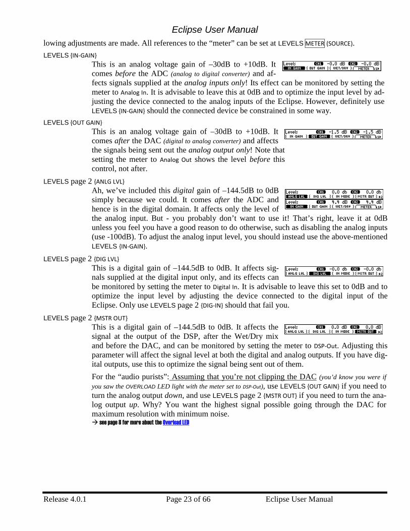
lowing adjustments are made. All references to the “meter” can be set at LEVELS METER (SOURCE). LEVELS {IN-GAIN}
This is an analog voltage gain of –30dB to +10dB. It comes before the ADC (analog to digital converter) and af-fects signals supplied at the analog inputs only! Its effect can be monitored by setting the meter to Analog In. It is advisable to leave this at 0dB and to optimize the input level by ad-justing the device connected to the analog inputs of the Eclipse. However, definitely use LEVELS {IN-GAIN} should the connected device be constrained in some way.
LEVELS {OUT GAIN} This is an analog voltage gain of –30dB to +10dB. It comes after the DAC (digital to analog converter) and affects the signals being sent out the analog output only! Note that setting the meter to Analog Out shows the level before this control, not after.
LEVELS page 2 {ANLG LVL} Ah, we’ve included this digital gain of –144.5dB to 0dB simply because we could. It comes after the ADC and hence is in the digital domain. It affects only the level of the analog input. But - you probably don’t want to use it! That’s right, leave it at 0dB unless you feel you have a good reason to do otherwise, such as disabling the analog inputs (use -100dB). To adjust the analog input level, you should instead use the above-mentioned LEVELS {IN-GAIN}.
LEVELS page 2 {DIG LVL} This is a digital gain of –144.5dB to 0dB. It affects sig-nals supplied at the digital input only, and its effects can be monitored by setting the meter to Digital In. It is advisable to leave this set to 0dB and to optimize the input level by adjusting the device connected to the digital input of the Eclipse. Only use LEVELS page 2 {DIG-IN} should that fail you.
LEVELS page 2 {MSTR OUT} This is a digital gain of –144.5dB to 0dB. It affects the signal at the output of the DSP, after the Wet/Dry mix and before the DAC, and can be monitored by setting the meter to DSP-Out. Adjusting this parameter will affect the signal level at both the digital and analog outputs. If you have dig-ital outputs, use this to optimize the signal being sent out of them. For the “audio purists”: Assuming that you’re not clipping the DAC (you’d know you were if you saw the OVERLOAD LED light with the meter set to DSP-Out), use LEVELS {OUT GAIN} if you need to turn the analog output down, and use LEVELS page 2 {MSTR OUT} if you need to turn the ana-log output up. Why? You want the highest signal possible going through the DAC for maximum resolution with minimum noise. see page 8 for more about the Overload LED
Eclipse User Manual
Eclipse User Manual Page 24 of 66 Release 4.0.1
Bypassing and Muting
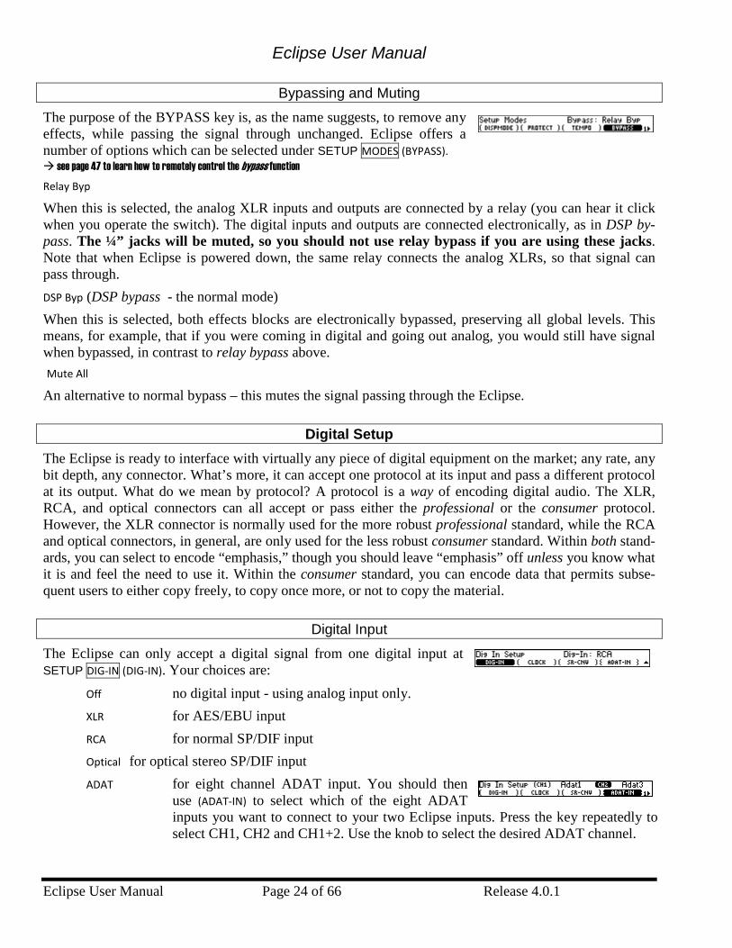
The purpose of the BYPASS key is, as the name suggests, to remove any effects, while passing the signal through unchanged. Eclipse offers a number of options which can be selected under SETUP MODES (BYPASS). see page 47 to learn how to remotely control the bypass function Relay Byp When this is selected, the analog XLR inputs and outputs are connected by a relay (you can hear it click when you operate the switch). The digital inputs and outputs are connected electronically, as in DSP by-pass. The ¼” jacks will be muted, so you should not use relay bypass if you are using these jacks. Note that when Eclipse is powered down, the same relay connects the analog XLRs, so that signal can pass through. DSP Byp (DSP bypass - the normal mode) When this is selected, both effects blocks are electronically bypassed, preserving all global levels. This means, for example, that if you were coming in digital and going out analog, you would still have signal when bypassed, in contrast to relay bypass above. Mute All An alternative to normal bypass – this mutes the signal passing through the Eclipse.
Digital Setup The Eclipse is ready to interface with virtually any piece of digital equipment on the market; any rate, any bit depth, any connector. What’s more, it can accept one protocol at its input and pass a different protocol at its output. What do we mean by protocol? A protocol is a way of encoding digital audio. The XLR, RCA, and optical connectors can all accept or pass either the professional or the consumer protocol. However, the XLR connector is normally used for the more robust professional standard, while the RCA and optical connectors, in general, are only used for the less robust consumer standard. Within both stand-ards, you can select to encode “emphasis,” though you should leave “emphasis” off unless you know what it is and feel the need to use it. Within the consumer standard, you can encode data that permits subse-quent users to either copy freely, to copy once more, or not to copy the material.
Digital Input
The Eclipse can only accept a digital signal from one digital input at SETUP DIG-IN (DIG-IN). Your choices are:
Off no digital input - using analog input only. XLR for AES/EBU input RCA for normal SP/DIF input Optical for optical stereo SP/DIF input ADAT for eight channel ADAT input. You should then
use (ADAT-IN) to select which of the eight ADAT inputs you want to connect to your two Eclipse inputs. Press the key repeatedly to select CH1, CH2 and CH1+2. Use the knob to select the desired ADAT channel.
Eclipse User Manual
Release 4.0.1 Page 25 of 66 Eclipse User Manual
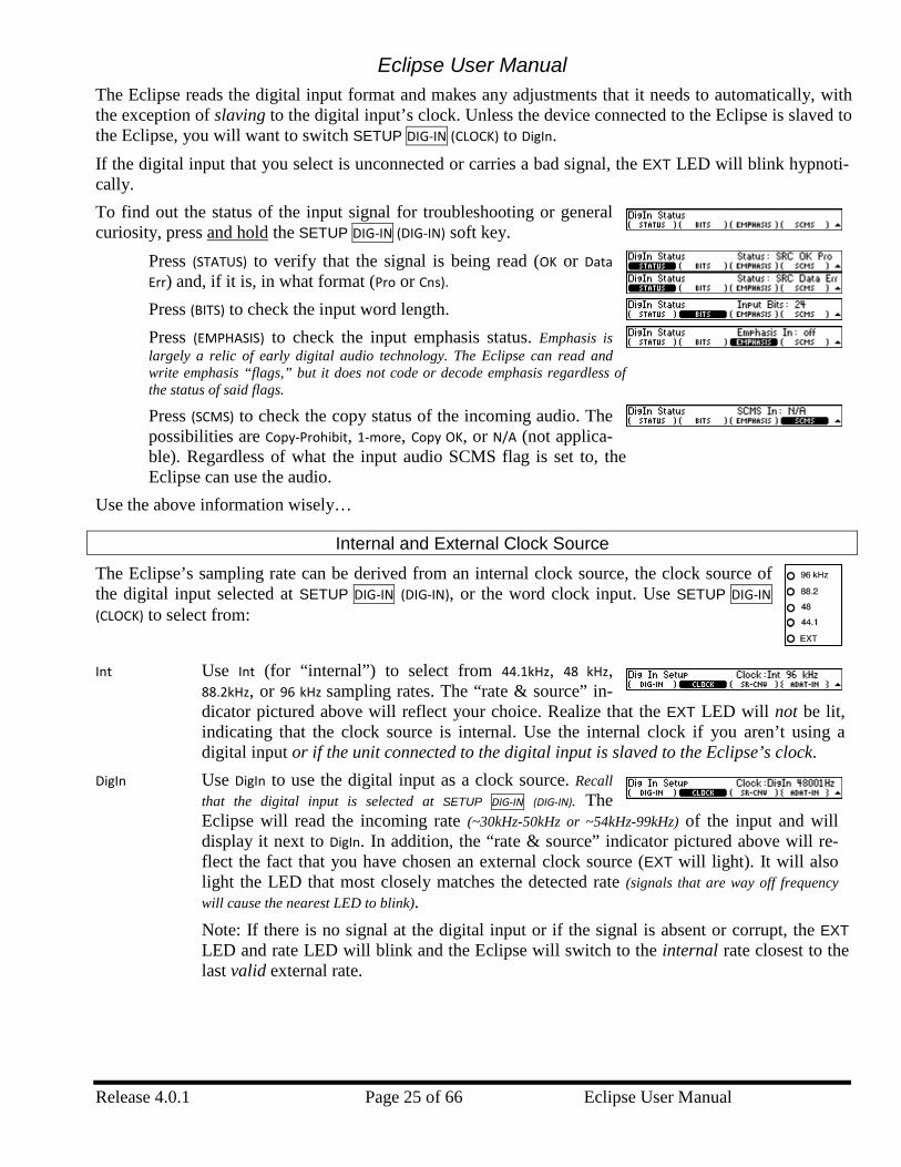
The Eclipse reads the digital input format and makes any adjustments that it needs to automatically, with the exception of slaving to the digital input’s clock. Unless the device connected to the Eclipse is slaved to the Eclipse, you will want to switch SETUP DIG-IN (CLOCK) to DigIn. If the digital input that you select is unconnected or carries a bad signal, the EXT LED will blink hypnoti-cally. To find out the status of the input signal for troubleshooting or general curiosity, press and hold the SETUP DIG-IN (DIG-IN) soft key.
Press (STATUS) to verify that the signal is being read (OK or Data Err) and, if it is, in what format (Pro or Cns). Press (BITS) to check the input word length. Press (EMPHASIS) to check the input emphasis status. Emphasis is largely a relic of early digital audio technology. The Eclipse can read and write emphasis “flags,” but it does not code or decode emphasis regardless of the status of said flags.
Press (SCMS) to check the copy status of the incoming audio. The possibilities are Copy-Prohibit, 1-more, Copy OK, or N/A (not applica-ble). Regardless of what the input audio SCMS flag is set to, the Eclipse can use the audio.
Use the above information wisely…
Internal and External Clock Source
The Eclipse’s sampling rate can be derived from an internal clock source, the clock source of the digital input selected at SETUP DIG-IN (DIG-IN), or the word clock input. Use SETUP DIG-IN (CLOCK) to select from: Int Use Int (for “internal”) to select from 44.1kHz, 48 kHz,
88.2kHz, or 96 kHz sampling rates. The “rate & source” in-dicator pictured above will reflect your choice. Realize that the EXT LED will not be lit, indicating that the clock source is internal. Use the internal clock if you aren’t using a digital input or if the unit connected to the digital input is slaved to the Eclipse’s clock.
DigIn Use DigIn to use the digital input as a clock source. Recall that the digital input is selected at SETUP DIG-IN (DIG-IN). The Eclipse will read the incoming rate (~30kHz-50kHz or ~54kHz-99kHz) of the input and will display it next to DigIn. In addition, the “rate & source” indicator pictured above will re-flect the fact that you have chosen an external clock source (EXT will light). It will also light the LED that most closely matches the detected rate (signals that are way off frequency will cause the nearest LED to blink). Note: If there is no signal at the digital input or if the signal is absent or corrupt, the EXT LED and rate LED will blink and the Eclipse will switch to the internal rate closest to the last valid external rate.
Eclipse User Manual
Eclipse User Manual Page 26 of 66 Release 4.0.1
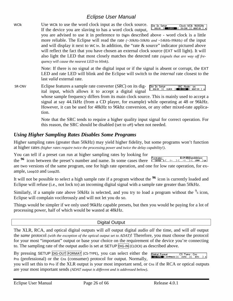
WClk Use WClk to use the word clock input as the clock source. If the device you are slaving to has a word clock output, you are advised to use it in preference to DigIn described above - word clock is a little more reliable. The Eclipse will read the rate (~30kHz-50kHz and ~54kHz-99kHz) of the input and will display it next to WC In. In addition, the “rate & source” indicator pictured above will reflect the fact that you have chosen an external clock source (EXT will light). It will also light the LED that most closely matches the detected rate (signals that are way off fre-quency will cause the nearest LED to blink). Note: If there is no signal at the digital input or if the signal is absent or corrupt, the EXT LED and rate LED will blink and the Eclipse will switch to the internal rate closest to the last valid external rate.
SR-CNV Eclipse features a sample rate converter (SRC) on its dig-ital input, which allows it to accept a digital signal whose sample frequency differs from its main clock source. This is mainly used to accept a signal at say 44.1kHz (from a CD player, for example) while operating at 48 or 96kHz. However, it can be used for 48kHz to 96khz conversion, or any other mixed-rate applica-tion. Note that the SRC tends to require a higher quality input signal for correct operation. For this reason, the SRC should be disabled (set to off) when not needed.
Using Higher Sampling Rates Disables Some Programs Higher sampling rates (greater than 50kHz) may yield higher fidelity, but some programs won’t function at higher rates (higher rates require twice the processing power and twice the delay capability!). You can tell if a preset can run at higher sampling rates by looking for the 96 icon between the preset’s number and name. In some cases there are two versions of the same program, one for high rate operation, and one for low rate operation, for ex-ample, Loop10 and Loop20.
It will not be possible to select a high sample rate if a program without the 96 icon is currently loaded and Eclipse will refuse (i.e., not lock to) an incoming digital signal with a sample rate greater than 50kHz.
Similarly, if a sample rate above 50kHz is selected, and you try to load a program without the 96 icon, Eclipse will complain vociferously and will not let you do so. Things would be simpler if we only used 96kHz capable presets, but then you would be paying for a lot of processing power, half of which would be wasted at 48kHz.
Digital Output
The XLR, RCA, and optical digital outputs will all output digital audio all the time, and will all output the same protocol (with the exception of the optical output set to ADAT)! Therefore, you must choose the protocol for your most “important” output or base your choice on the requirement of the device you’re connecting to. The sampling rate of the output audio is set at SETUP DIG-IN (CLOCK) as described above. By pressing SETUP DIG-OUT FORMAT (CS-TYPE), you can select either the Pro (professional) or the Cns (consumer) protocol for output. Normally, you will set this to Pro if the XLR output is your most important send, or Cns if the RCA or optical outputs are your most important sends (ADAT output is different and is addressed below).
Eclipse User Manual
Release 4.0.1 Page 27 of 66 Eclipse User Manual
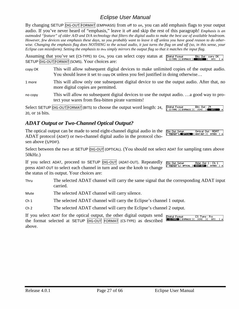
By changing SETUP DIG-OUT FORMAT (EMPHASIS) from off to on, you can add emphasis flags to your output audio. If you’ve never heard of “emphasis,” leave it off and skip the rest of this paragraph! Emphasis is an outmoded “feature” of older A/D and D/A technology that filters the digital audio to make the best use of available headroom. However, few devices use emphasis these days, so you probably want to leave it off unless you have good reason to do other-wise. Changing the emphasis flag does NOTHING to the actual audio, it just turns the flag on and off (so, in this sense, your Eclipse can misinform). Setting the emphasis to thru simply mirrors the output flag so that it matches the input flag.
Assuming that you’ve set (CS-TYPE) to Cns, you can select copy status at SETUP DIG-OUT FORMAT (SCMS). Your choices are: copy OK This will allow subsequent digital devices to make unlimited copies of the output audio.
You should leave it set to copy OK unless you feel justified in doing otherwise… 1 more This will allow only one subsequent digital device to use the output audio. After that, no
more digital copies are permitted. no copy This will allow no subsequent digital devices to use the output audio. …a good way to pro-
tect your wares from flea-bitten pirate varmints! Select SETUP DIG-OUT FORMAT (BITS) to choose the output word length: 24, 20, or 16 bits.
ADAT Output or Two-Channel Optical Output? The optical output can be made to send eight-channel digital audio in the ADAT protocol (ADAT) or two-channel digital audio in the protocol cho-sen above (S/PDIF). Select between the two at SETUP DIG-OUT (OPTICAL). (You should not select ADAT for sampling rates above 50kHz.) If you select ADAT, proceed to SETUP DIG-OUT (ADAT-OUT). Repeatedly press ADAT-OUT to select each channel in turn and use the knob to change the status of its output. Your choices are: Thru The selected ADAT channel will carry the same signal that the corresponding ADAT input
carried. Mute The selected ADAT channel will carry silence. Ch 1 The selected ADAT channel will carry the Eclipse’s channel 1 output. Ch 2 The selected ADAT channel will carry the Eclipse’s channel 2 output. If you select ADAT for the optical output, the other digital outputs send the format selected at SETUP DIG-OUT FORMAT (CS-TYPE) as described above.
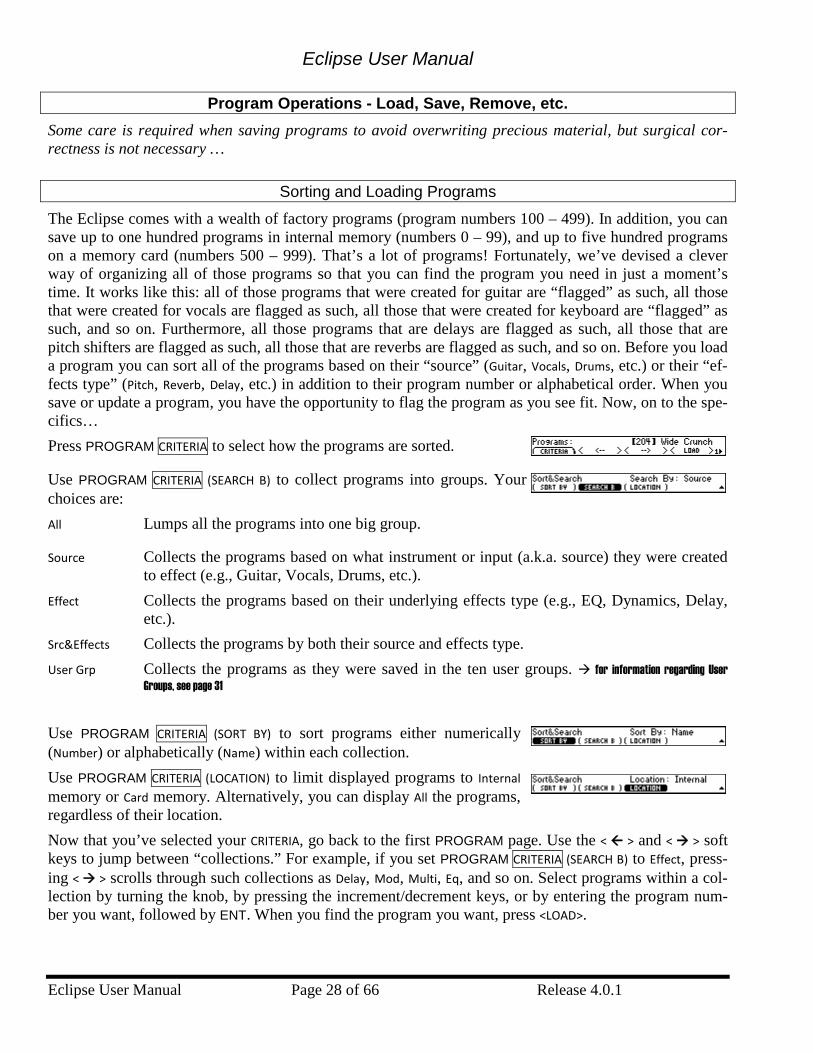
Eclipse User Manual
Eclipse User Manual Page 28 of 66 Release 4.0.1
Program Operations - Load, Save, Remove, etc. Some care is required when saving programs to avoid overwriting precious material, but surgical cor-rectness is not necessary …
Sorting and Loading Programs
The Eclipse comes with a wealth of factory programs (program numbers 100 – 499). In addition, you can save up to one hundred programs in internal memory (numbers 0 – 99), and up to five hundred programs on a memory card (numbers 500 – 999). That’s a lot of programs! Fortunately, we’ve devised a clever way of organizing all of those programs so that you can find the program you need in just a moment’s time. It works like this: all of those programs that were created for guitar are “flagged” as such, all those that were created for vocals are flagged as such, all those that were created for keyboard are “flagged” as such, and so on. Furthermore, all those programs that are delays are flagged as such, all those that are pitch shifters are flagged as such, all those that are reverbs are flagged as such, and so on. Before you load a program you can sort all of the programs based on their “source” (Guitar, Vocals, Drums, etc.) or their “ef-fects type” (Pitch, Reverb, Delay, etc.) in addition to their program number or alphabetical order. When you save or update a program, you have the opportunity to flag the program as you see fit. Now, on to the spe-cifics… Press PROGRAM CRITERIA to select how the programs are sorted.
Use PROGRAM CRITERIA (SEARCH B) to collect programs into groups. Your choices are: All Lumps all the programs into one big group.
Source Collects the programs based on what instrument or input (a.k.a. source) they were created to effect (e.g., Guitar, Vocals, Drums, etc.).
Effect Collects the programs based on their underlying effects type (e.g., EQ, Dynamics, Delay, etc.).
Src&Effects Collects the programs by both their source and effects type. User Grp Collects the programs as they were saved in the ten user groups. for information regarding User
Groups, see page 31 Use PROGRAM CRITERIA (SORT BY) to sort programs either numerically (Number) or alphabetically (Name) within each collection. Use PROGRAM CRITERIA (LOCATION) to limit displayed programs to Internal memory or Card memory. Alternatively, you can display All the programs, regardless of their location. Now that you’ve selected your CRITERIA, go back to the first PROGRAM page. Use the < > and < > soft keys to jump between “collections.” For example, if you set PROGRAM CRITERIA (SEARCH B) to Effect, press-ing < > scrolls through such collections as Delay, Mod, Multi, Eq, and so on. Select programs within a col-lection by turning the knob, by pressing the increment/decrement keys, or by entering the program num-ber you want, followed by ENT. When you find the program you want, press <LOAD>.
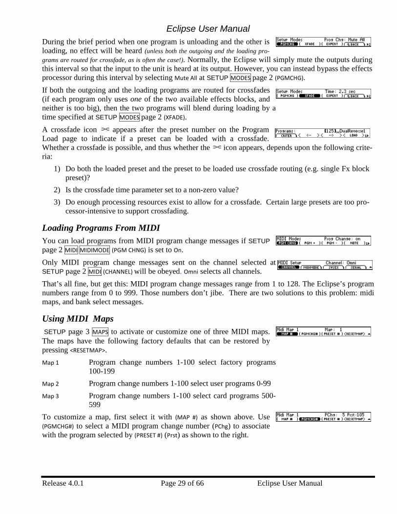
Eclipse User Manual
Release 4.0.1 Page 29 of 66 Eclipse User Manual
During the brief period when one program is unloading and the other is loading, no effect will be heard (unless both the outgoing and the loading pro-grams are routed for crossfade, as is often the case!). Normally, the Eclipse will simply mute the outputs during this interval so that the input to the unit is heard at its output. However, you can instead bypass the effects processor during this interval by selecting Mute All at SETUP MODES page 2 (PGMCHG). If both the outgoing and the loading programs are routed for crossfades (if each program only uses one of the two available effects blocks, and neither is too big), then the two programs will blend during loading by a time specified at SETUP MODES page 2 (XFADE). A crossfade icon appears after the preset number on the Program Load page to indicate if a preset can be loaded with a crossfade. Whether a crossfade is possible, and thus whether the icon appears, depends upon the following crite-ria:
1) Do both the loaded preset and the preset to be loaded use crossfade routing (e.g. single Fx block preset)?
2) Is the crossfade time parameter set to a non-zero value? 3) Do enough processing resources exist to allow for a crossfade. Certain large presets are too pro-
cessor-intensive to support crossfading.
Loading Programs From MIDI You can load programs from MIDI program change messages if SETUP page 2 MIDI MIDIMODE (PGM CHNG) is set to On. Only MIDI program change messages sent on the channel selected at SETUP page 2 MIDI (CHANNEL) will be obeyed. Omni selects all channels. That’s all fine, but get this: MIDI program change messages range from 1 to 128. The Eclipse’s program numbers range from 0 to 999. Those numbers don’t jibe. There are two solutions to this problem: midi maps, and bank select messages.
Using MIDI Maps SETUP page 3 MAPS to activate or customize one of three MIDI maps. The maps have the following factory defaults that can be restored by pressing <RESETMAP>. Map 1 Program change numbers 1-100 select factory programs
100-199 Map 2 Program change numbers 1-100 select user programs 0-99 Map 3 Program change numbers 1-100 select card programs 500-
599 To customize a map, first select it with (MAP #) as shown above. Use (PGMCHG#) to select a MIDI program change number (PChg) to associate with the program selected by (PRESET #) (Prst) as shown to the right.
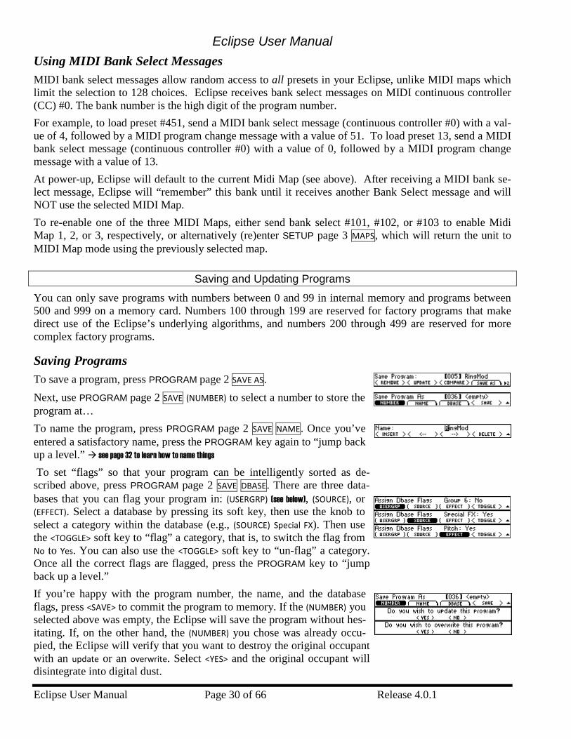
Eclipse User Manual
Eclipse User Manual Page 30 of 66 Release 4.0.1
Using MIDI Bank Select Messages MIDI bank select messages allow random access to all presets in your Eclipse, unlike MIDI maps which limit the selection to 128 choices. Eclipse receives bank select messages on MIDI continuous controller (CC) #0. The bank number is the high digit of the program number. For example, to load preset #451, send a MIDI bank select message (continuous controller #0) with a val-ue of 4, followed by a MIDI program change message with a value of 51. To load preset 13, send a MIDI bank select message (continuous controller #0) with a value of 0, followed by a MIDI program change message with a value of 13. At power-up, Eclipse will default to the current Midi Map (see above). After receiving a MIDI bank se-lect message, Eclipse will “remember” this bank until it receives another Bank Select message and will NOT use the selected MIDI Map. To re-enable one of the three MIDI Maps, either send bank select #101, #102, or #103 to enable Midi Map 1, 2, or 3, respectively, or alternatively (re)enter SETUP page 3 MAPS, which will return the unit to MIDI Map mode using the previously selected map.
Saving and Updating Programs
You can only save programs with numbers between 0 and 99 in internal memory and programs between 500 and 999 on a memory card. Numbers 100 through 199 are reserved for factory programs that make direct use of the Eclipse’s underlying algorithms, and numbers 200 through 499 are reserved for more complex factory programs.
Saving Programs To save a program, press PROGRAM page 2 SAVE AS. Next, use PROGRAM page 2 SAVE (NUMBER) to select a number to store the program at… To name the program, press PROGRAM page 2 SAVE NAME. Once you’ve entered a satisfactory name, press the PROGRAM key again to “jump back up a level.” see page 32 to learn how to name things
To set “flags” so that your program can be intelligently sorted as de-scribed above, press PROGRAM page 2 SAVE DBASE. There are three data-bases that you can flag your program in: (USERGRP) (see below), (SOURCE), or (EFFECT). Select a database by pressing its soft key, then use the knob to select a category within the database (e.g., (SOURCE) Special FX). Then use the <TOGGLE> soft key to “flag” a category, that is, to switch the flag from No to Yes. You can also use the <TOGGLE> soft key to “un-flag” a category. Once all the correct flags are flagged, press the PROGRAM key to “jump back up a level.” If you’re happy with the program number, the name, and the database flags, press <SAVE> to commit the program to memory. If the (NUMBER) you selected above was empty, the Eclipse will save the program without hes-itating. If, on the other hand, the (NUMBER) you chose was already occu-pied, the Eclipse will verify that you want to destroy the original occupant with an update or an overwrite. Select <YES> and the original occupant will disintegrate into digital dust.
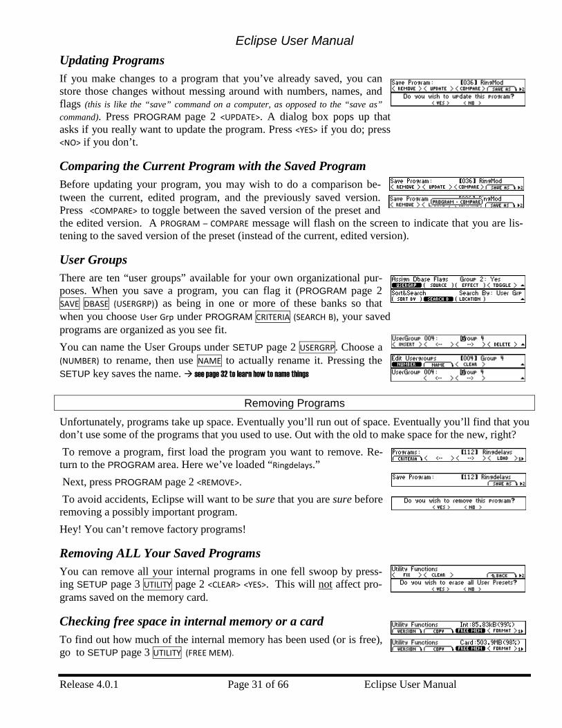
Eclipse User Manual
Release 4.0.1 Page 31 of 66 Eclipse User Manual
Updating Programs If you make changes to a program that you’ve already saved, you can store those changes without messing around with numbers, names, and flags (this is like the “save” command on a computer, as opposed to the “save as” command). Press PROGRAM page 2 <UPDATE>. A dialog box pops up that asks if you really want to update the program. Press <YES> if you do; press <NO> if you don’t.
Comparing the Current Program with the Saved Program Before updating your program, you may wish to do a comparison be-tween the current, edited program, and the previously saved version. Press <COMPARE> to toggle between the saved version of the preset and the edited version. A PROGRAM – COMPARE message will flash on the screen to indicate that you are lis-tening to the saved version of the preset (instead of the current, edited version).
User Groups There are ten “user groups” available for your own organizational pur-poses. When you save a program, you can flag it (PROGRAM page 2 SAVE DBASE (USERGRP)) as being in one or more of these banks so that when you choose User Grp under PROGRAM CRITERIA (SEARCH B), your saved programs are organized as you see fit. You can name the User Groups under SETUP page 2 USERGRP. Choose a (NUMBER) to rename, then use NAME to actually rename it. Pressing the SETUP key saves the name. see page 32 to learn how to name things
Removing Programs
Unfortunately, programs take up space. Eventually you’ll run out of space. Eventually you’ll find that you don’t use some of the programs that you used to use. Out with the old to make space for the new, right? To remove a program, first load the program you want to remove. Re-turn to the PROGRAM area. Here we’ve loaded “Ringdelays.” Next, press PROGRAM page 2 <REMOVE>. To avoid accidents, Eclipse will want to be sure that you are sure before removing a possibly important program. Hey! You can’t remove factory programs!
Removing ALL Your Saved Programs You can remove all your internal programs in one fell swoop by press-ing SETUP page 3 UTILITY page 2 <CLEAR> <YES>. This will not affect pro-grams saved on the memory card.
Checking free space in internal memory or a card To find out how much of the internal memory has been used (or is free), go to SETUP page 3 UTILITY (FREE MEM).
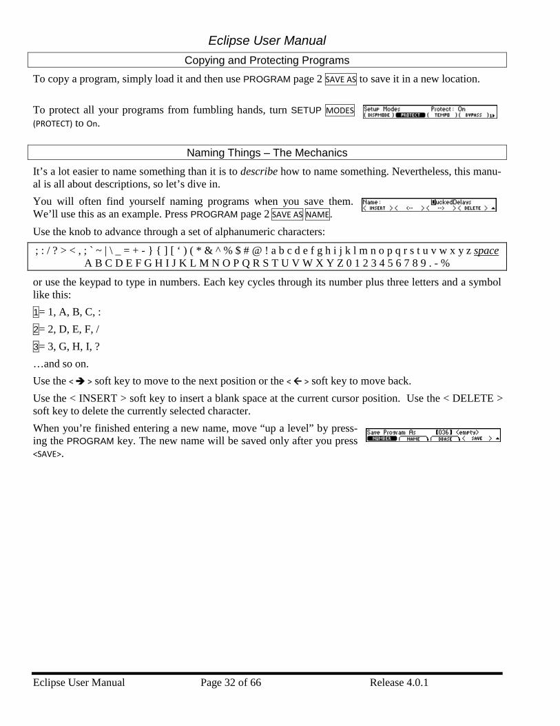
Eclipse User Manual
Eclipse User Manual Page 32 of 66 Release 4.0.1
Copying and Protecting Programs
To copy a program, simply load it and then use PROGRAM page 2 SAVE AS to save it in a new location.
To protect all your programs from fumbling hands, turn SETUP MODES (PROTECT) to On.
Naming Things – The Mechanics
It’s a lot easier to name something than it is to describe how to name something. Nevertheless, this manu-al is all about descriptions, so let’s dive in. You will often find yourself naming programs when you save them. We’ll use this as an example. Press PROGRAM page 2 SAVE AS NAME. Use the knob to advance through a set of alphanumeric characters:
; : / ? > < , ; ` ~ | \ _ = + - } { ] [ ‘ ) ( * & ^ % $ # @ ! a b c d e f g h i j k l m n o p q r s t u v w x y z space A B C D E F G H I J K L M N O P Q R S T U V W X Y Z 0 1 2 3 4 5 6 7 8 9 . - %
or use the keypad to type in numbers. Each key cycles through its number plus three letters and a symbol like this: 1= 1, A, B, C, : 2= 2, D, E, F, / 3= 3, G, H, I, ? …and so on. Use the < > soft key to move to the next position or the < > soft key to move back. Use the < INSERT > soft key to insert a blank space at the current cursor position. Use the < DELETE > soft key to delete the currently selected character. When you’re finished entering a new name, move “up a level” by press-ing the PROGRAM key. The new name will be saved only after you press <SAVE>.
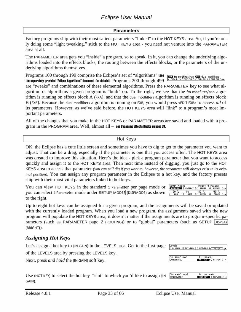
Eclipse User Manual
Release 4.0.1 Page 33 of 66 Eclipse User Manual
Parameters Factory programs ship with their most salient parameters “linked” to the HOT KEYS area. So, if you’re on-ly doing some “light tweaking,” stick to the HOT KEYS area - you need not venture into the PARAMETER area at all. The PARAMETER area gets you “inside” a program, so to speak. In it, you can change the underlying algo-rithms loaded into the effects blocks, the routing between the effects blocks, or the parameters of the un-derlying algorithms themselves. Programs 100 through 199 comprise the Eclipse’s set of “algorithms” (see the separately provided “Eclipse Algorithms” document for details). Programs 200 through 499 are “tweaks” and combinations of these elemental algorithms. Press the PARAMETER key to see what al-gorithm or algorithms a given program is “built” on. To the right, we see that the fm modfilter/pan algo-rithm is running on effects block A (FXA), and that the dual modfilters algorithm is running on effects block B (FXB). Because the dual modfilters algorithm is running on FXB, you would press <EDIT FXB> to access all of its parameters. However, as we’ve said before, the HOT KEYS area will “link” to a program’s most im-portant parameters. All of the changes that you make in the HOT KEYS or PARAMETER areas are saved and loaded with a pro-gram in the PROGRAM area. Well, almost all – see Bypassing Effects Blocks on page 39.
Hot Keys
OK, the Eclipse has a cute little screen and sometimes you have to dig to get to the parameter you want to adjust. That can be a drag, especially if the parameter is one that you access often. The HOT KEYS area was created to improve this situation. Here’s the idea - pick a program parameter that you want to access quickly and assign it to the HOT KEYS area. Then next time instead of digging, you just go to the HOT KEYS area to access that parameter (you can still dig if you want to, however, the parameter will always exist in its orig-inal position). You can assign any program parameter in the Eclipse to a hot key, and the factory presets ship with their most vital parameters linked to hot keys. You can view HOT KEYS in the standard 1 Parameter per page mode or you can select 4 Parameter mode under SETUP MODES (DISPMODE) as shown to the right. Up to eight hot keys can be assigned for a given program, and the assignments will be saved or updated with the currently loaded program. When you load a new program, the assignments saved with the new program will populate the HOT KEYS area; it doesn’t matter if the assignments are to program-specific pa-rameters (such as PARAMETER page 2 (ROUTING)) or to “global” parameters (such as SETUP DISPLAY (BRIGHT)).
Assigning Hot Keys Let’s assign a hot key to {IN GAIN} in the LEVELS area. Get to the first page of the LEVELS area by pressing the LEVELS key. Next, press and hold the {IN GAIN} soft key. Use (HOT KEY) to select the hot key “slot” to which you’d like to assign {IN GAIN}.
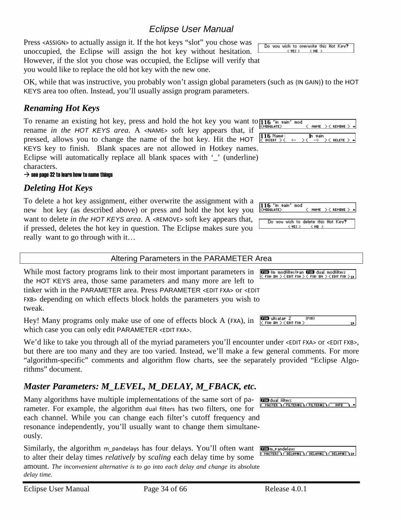
Eclipse User Manual
Eclipse User Manual Page 34 of 66 Release 4.0.1
Press <ASSIGN> to actually assign it. If the hot keys “slot” you chose was unoccupied, the Eclipse will assign the hot key without hesitation. However, if the slot you chose was occupied, the Eclipse will verify that you would like to replace the old hot key with the new one. OK, while that was instructive, you probably won’t assign global parameters (such as {IN GAIN}) to the HOT KEYS area too often. Instead, you’ll usually assign program parameters.
Renaming Hot Keys To rename an existing hot key, press and hold the hot key you want to rename in the HOT KEYS area. A <NAME> soft key appears that, if pressed, allows you to change the name of the hot key. Hit the HOT KEYS key to finish. Blank spaces are not allowed in Hotkey names. Eclipse will automatically replace all blank spaces with ‘_’ (underline) characters. see page 32 to learn how to name things
Deleting Hot Keys To delete a hot key assignment, either overwrite the assignment with a new hot key (as described above) or press and hold the hot key you want to delete in the HOT KEYS area. A <REMOVE> soft key appears that, if pressed, deletes the hot key in question. The Eclipse makes sure you really want to go through with it…
Altering Parameters in the PARAMETER Area
While most factory programs link to their most important parameters in the HOT KEYS area, those same parameters and many more are left to tinker with in the PARAMETER area. Press PARAMETER <EDIT FXA> or <EDIT FXB> depending on which effects block holds the parameters you wish to tweak. Hey! Many programs only make use of one of effects block A (FXA), in which case you can only edit PARAMETER <EDIT FXA>. We’d like to take you through all of the myriad parameters you’ll encounter under <EDIT FXA> or <EDIT FXB>, but there are too many and they are too varied. Instead, we’ll make a few general comments. For more “algorithm-specific” comments and algorithm flow charts, see the separately provided “Eclipse Algo-rithms” document.
Master Parameters: M_LEVEL, M_DELAY, M_FBACK, etc. Many algorithms have multiple implementations of the same sort of pa-rameter. For example, the algorithm dual filters has two filters, one for each channel. While you can change each filter’s cutoff frequency and resonance independently, you’ll usually want to change them simultane-ously. Similarly, the algorithm m_pandelays has four delays. You’ll often want to alter their delay times relatively by scaling each delay time by some amount. The inconvenient alternative is to go into each delay and change its absolute delay time.
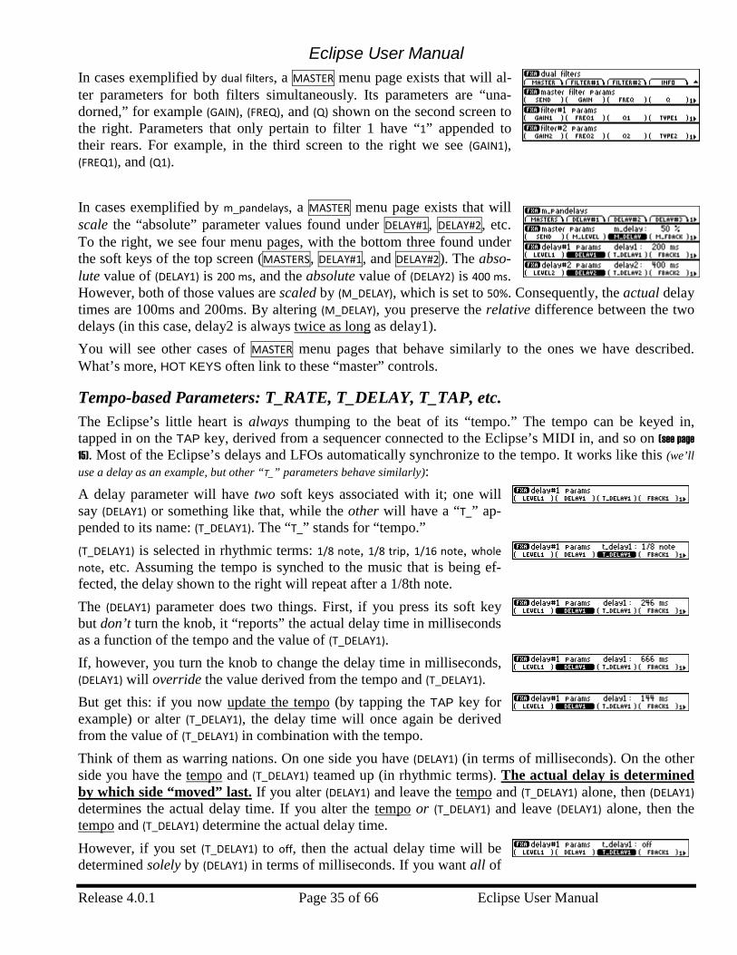
Eclipse User Manual
Release 4.0.1 Page 35 of 66 Eclipse User Manual
In cases exemplified by dual filters, a MASTER menu page exists that will al-ter parameters for both filters simultaneously. Its parameters are “una-dorned,” for example (GAIN), (FREQ), and (Q) shown on the second screen to the right. Parameters that only pertain to filter 1 have “1” appended to their rears. For example, in the third screen to the right we see (GAIN1), (FREQ1), and (Q1). In cases exemplified by m_pandelays, a MASTER menu page exists that will scale the “absolute” parameter values found under DELAY#1, DELAY#2, etc. To the right, we see four menu pages, with the bottom three found under the soft keys of the top screen (MASTERS, DELAY#1, and DELAY#2). The abso-lute value of (DELAY1) is 200 ms, and the absolute value of (DELAY2) is 400 ms. However, both of those values are scaled by (M_DELAY), which is set to 50%. Consequently, the actual delay times are 100ms and 200ms. By altering (M_DELAY), you preserve the relative difference between the two delays (in this case, delay2 is always twice as long as delay1). You will see other cases of MASTER menu pages that behave similarly to the ones we have described. What’s more, HOT KEYS often link to these “master” controls.
Tempo-based Parameters: T_RATE, T_DELAY, T_TAP, etc. The Eclipse’s little heart is always thumping to the beat of its “tempo.” The tempo can be keyed in, tapped in on the TAP key, derived from a sequencer connected to the Eclipse’s MIDI in, and so on (see page 15). Most of the Eclipse’s delays and LFOs automatically synchronize to the tempo. It works like this (we’ll use a delay as an example, but other “T_” parameters behave similarly): A delay parameter will have two soft keys associated with it; one will say (DELAY1) or something like that, while the other will have a “T_” ap-pended to its name: (T_DELAY1). The “T_” stands for “tempo.” (T_DELAY1) is selected in rhythmic terms: 1/8 note, 1/8 trip, 1/16 note, whole note, etc. Assuming the tempo is synched to the music that is being ef-fected, the delay shown to the right will repeat after a 1/8th note. The (DELAY1) parameter does two things. First, if you press its soft key but don’t turn the knob, it “reports” the actual delay time in milliseconds as a function of the tempo and the value of (T_DELAY1). If, however, you turn the knob to change the delay time in milliseconds, (DELAY1) will override the value derived from the tempo and (T_DELAY1). But get this: if you now update the tempo (by tapping the TAP key for example) or alter (T_DELAY1), the delay time will once again be derived from the value of (T_DELAY1) in combination with the tempo. Think of them as warring nations. On one side you have (DELAY1) (in terms of milliseconds). On the other side you have the tempo and (T_DELAY1) teamed up (in rhythmic terms). The actual delay is determined by which side “moved” last. If you alter (DELAY1) and leave the tempo and (T_DELAY1) alone, then (DELAY1) determines the actual delay time. If you alter the tempo or (T_DELAY1) and leave (DELAY1) alone, then the tempo and (T_DELAY1) determine the actual delay time. However, if you set (T_DELAY1) to off, then the actual delay time will be determined solely by (DELAY1) in terms of milliseconds. If you want all of
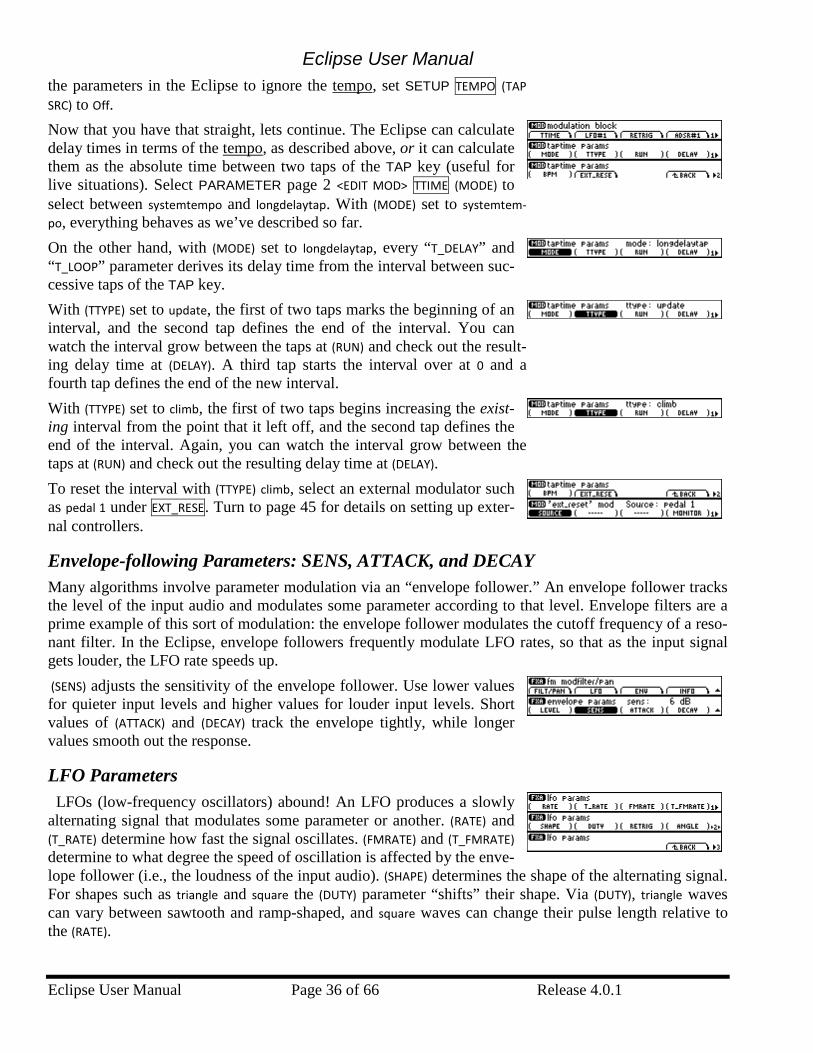
Eclipse User Manual
Eclipse User Manual Page 36 of 66 Release 4.0.1
the parameters in the Eclipse to ignore the tempo, set SETUP TEMPO (TAP SRC) to Off. Now that you have that straight, lets continue. The Eclipse can calculate delay times in terms of the tempo, as described above, or it can calculate them as the absolute time between two taps of the TAP key (useful for live situations). Select PARAMETER page 2 <EDIT MOD> TTIME (MODE) to select between systemtempo and longdelaytap. With (MODE) set to systemtem-po, everything behaves as we’ve described so far. On the other hand, with (MODE) set to longdelaytap, every “T_DELAY” and “T_LOOP” parameter derives its delay time from the interval between suc-cessive taps of the TAP key. With (TTYPE) set to update, the first of two taps marks the beginning of an interval, and the second tap defines the end of the interval. You can watch the interval grow between the taps at (RUN) and check out the result-ing delay time at (DELAY). A third tap starts the interval over at 0 and a fourth tap defines the end of the new interval. With (TTYPE) set to climb, the first of two taps begins increasing the exist-ing interval from the point that it left off, and the second tap defines the end of the interval. Again, you can watch the interval grow between the taps at (RUN) and check out the resulting delay time at (DELAY). To reset the interval with (TTYPE) climb, select an external modulator such as pedal 1 under EXT_RESE. Turn to page 45 for details on setting up exter-nal controllers.
Envelope-following Parameters: SENS, ATTACK, and DECAY Many algorithms involve parameter modulation via an “envelope follower.” An envelope follower tracks the level of the input audio and modulates some parameter according to that level. Envelope filters are a prime example of this sort of modulation: the envelope follower modulates the cutoff frequency of a reso-nant filter. In the Eclipse, envelope followers frequently modulate LFO rates, so that as the input signal gets louder, the LFO rate speeds up. (SENS) adjusts the sensitivity of the envelope follower. Use lower values for quieter input levels and higher values for louder input levels. Short values of (ATTACK) and (DECAY) track the envelope tightly, while longer values smooth out the response.
LFO Parameters LFOs (low-frequency oscillators) abound! An LFO produces a slowly alternating signal that modulates some parameter or another. (RATE) and (T_RATE) determine how fast the signal oscillates. (FMRATE) and (T_FMRATE) determine to what degree the speed of oscillation is affected by the enve-lope follower (i.e., the loudness of the input audio). (SHAPE) determines the shape of the alternating signal. For shapes such as triangle and square the (DUTY) parameter “shifts” their shape. Via (DUTY), triangle waves can vary between sawtooth and ramp-shaped, and square waves can change their pulse length relative to the (RATE).
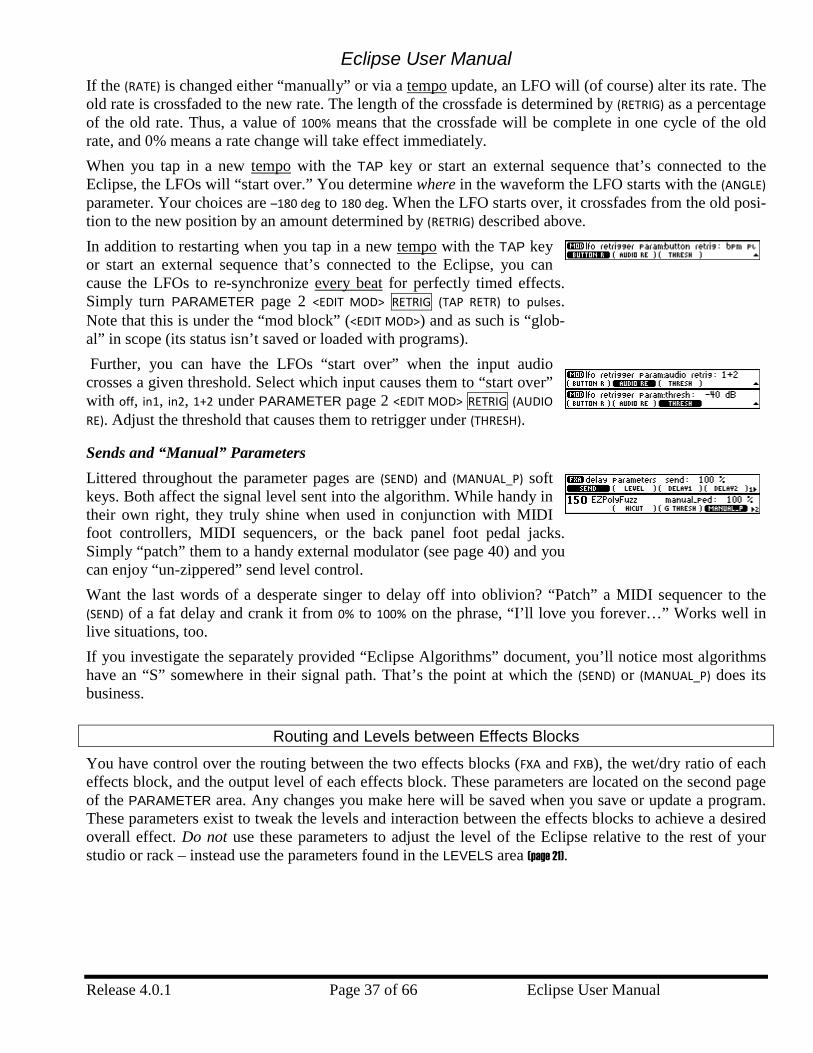
Eclipse User Manual
Release 4.0.1 Page 37 of 66 Eclipse User Manual
If the (RATE) is changed either “manually” or via a tempo update, an LFO will (of course) alter its rate. The old rate is crossfaded to the new rate. The length of the crossfade is determined by (RETRIG) as a percentage of the old rate. Thus, a value of 100% means that the crossfade will be complete in one cycle of the old rate, and 0% means a rate change will take effect immediately. When you tap in a new tempo with the TAP key or start an external sequence that’s connected to the Eclipse, the LFOs will “start over.” You determine where in the waveform the LFO starts with the (ANGLE) parameter. Your choices are –180 deg to 180 deg. When the LFO starts over, it crossfades from the old posi-tion to the new position by an amount determined by (RETRIG) described above. In addition to restarting when you tap in a new tempo with the TAP key or start an external sequence that’s connected to the Eclipse, you can cause the LFOs to re-synchronize every beat for perfectly timed effects. Simply turn PARAMETER page 2 <EDIT MOD> RETRIG (TAP RETR) to pulses. Note that this is under the “mod block” (<EDIT MOD>) and as such is “glob-al” in scope (its status isn’t saved or loaded with programs). Further, you can have the LFOs “start over” when the input audio crosses a given threshold. Select which input causes them to “start over” with off, in1, in2, 1+2 under PARAMETER page 2 <EDIT MOD> RETRIG (AUDIO RE). Adjust the threshold that causes them to retrigger under (THRESH).
Sends and “Manual” Parameters Littered throughout the parameter pages are (SEND) and (MANUAL_P) soft keys. Both affect the signal level sent into the algorithm. While handy in their own right, they truly shine when used in conjunction with MIDI foot controllers, MIDI sequencers, or the back panel foot pedal jacks. Simply “patch” them to a handy external modulator (see page 40) and you can enjoy “un-zippered” send level control. Want the last words of a desperate singer to delay off into oblivion? “Patch” a MIDI sequencer to the (SEND) of a fat delay and crank it from 0% to 100% on the phrase, “I’ll love you forever…” Works well in live situations, too. If you investigate the separately provided “Eclipse Algorithms” document, you’ll notice most algorithms have an “S” somewhere in their signal path. That’s the point at which the (SEND) or (MANUAL_P) does its business.
Routing and Levels between Effects Blocks
You have control over the routing between the two effects blocks (FXA and FXB), the wet/dry ratio of each effects block, and the output level of each effects block. These parameters are located on the second page of the PARAMETER area. Any changes you make here will be saved when you save or update a program. These parameters exist to tweak the levels and interaction between the effects blocks to achieve a desired overall effect. Do not use these parameters to adjust the level of the Eclipse relative to the rest of your studio or rack – instead use the parameters found in the LEVELS area (page 21).
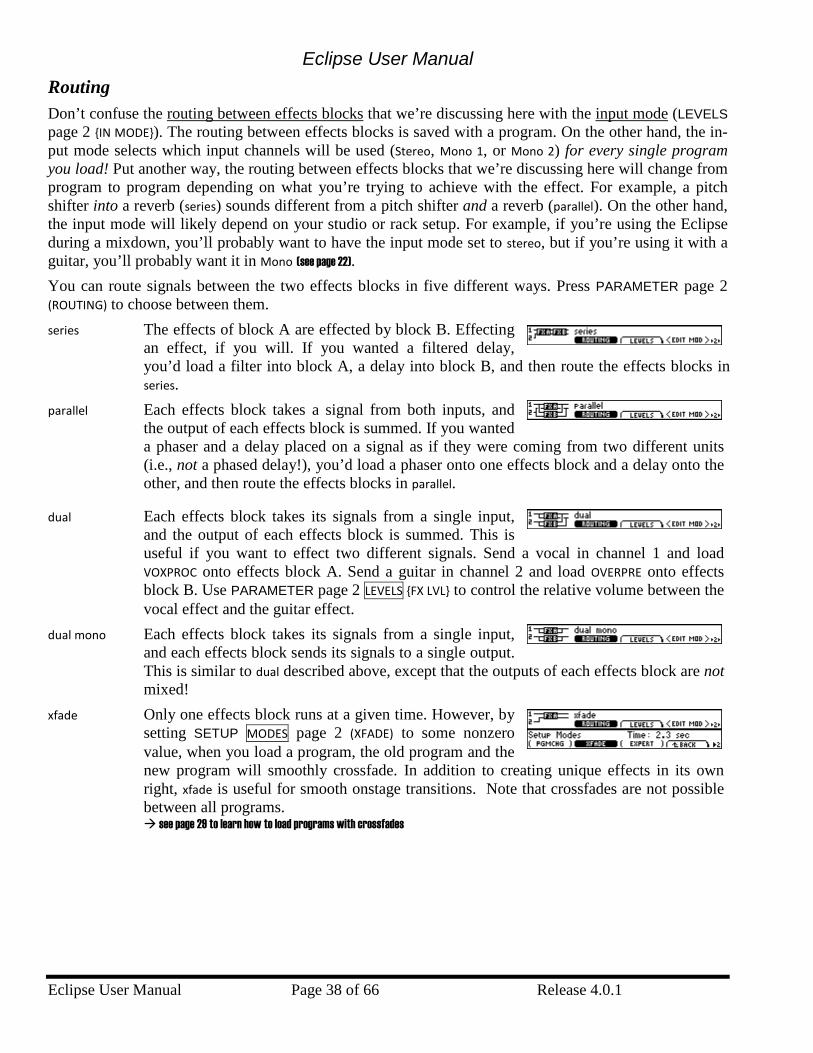
Eclipse User Manual
Eclipse User Manual Page 38 of 66 Release 4.0.1
Routing Don’t confuse the routing between effects blocks that we’re discussing here with the input mode (LEVELS page 2 {IN MODE}). The routing between effects blocks is saved with a program. On the other hand, the in-put mode selects which input channels will be used (Stereo, Mono 1, or Mono 2) for every single program you load! Put another way, the routing between effects blocks that we’re discussing here will change from program to program depending on what you’re trying to achieve with the effect. For example, a pitch shifter into a reverb (series) sounds different from a pitch shifter and a reverb (parallel). On the other hand, the input mode will likely depend on your studio or rack setup. For example, if you’re using the Eclipse during a mixdown, you’ll probably want to have the input mode set to stereo, but if you’re using it with a guitar, you’ll probably want it in Mono (see page 22). You can route signals between the two effects blocks in five different ways. Press PARAMETER page 2 (ROUTING) to choose between them. series The effects of block A are effected by block B. Effecting
an effect, if you will. If you wanted a filtered delay, you’d load a filter into block A, a delay into block B, and then route the effects blocks in series.
parallel Each effects block takes a signal from both inputs, and the output of each effects block is summed. If you wanted a phaser and a delay placed on a signal as if they were coming from two different units (i.e., not a phased delay!), you’d load a phaser onto one effects block and a delay onto the other, and then route the effects blocks in parallel.
dual Each effects block takes its signals from a single input, and the output of each effects block is summed. This is useful if you want to effect two different signals. Send a vocal in channel 1 and load VOXPROC onto effects block A. Send a guitar in channel 2 and load OVERPRE onto effects block B. Use PARAMETER page 2 LEVELS {FX LVL} to control the relative volume between the vocal effect and the guitar effect.
dual mono Each effects block takes its signals from a single input, and each effects block sends its signals to a single output. This is similar to dual described above, except that the outputs of each effects block are not mixed!
xfade Only one effects block runs at a given time. However, by setting SETUP MODES page 2 (XFADE) to some nonzero value, when you load a program, the old program and the new program will smoothly crossfade. In addition to creating unique effects in its own right, xfade is useful for smooth onstage transitions. Note that crossfades are not possible between all programs. see page 29 to learn how to load programs with crossfades
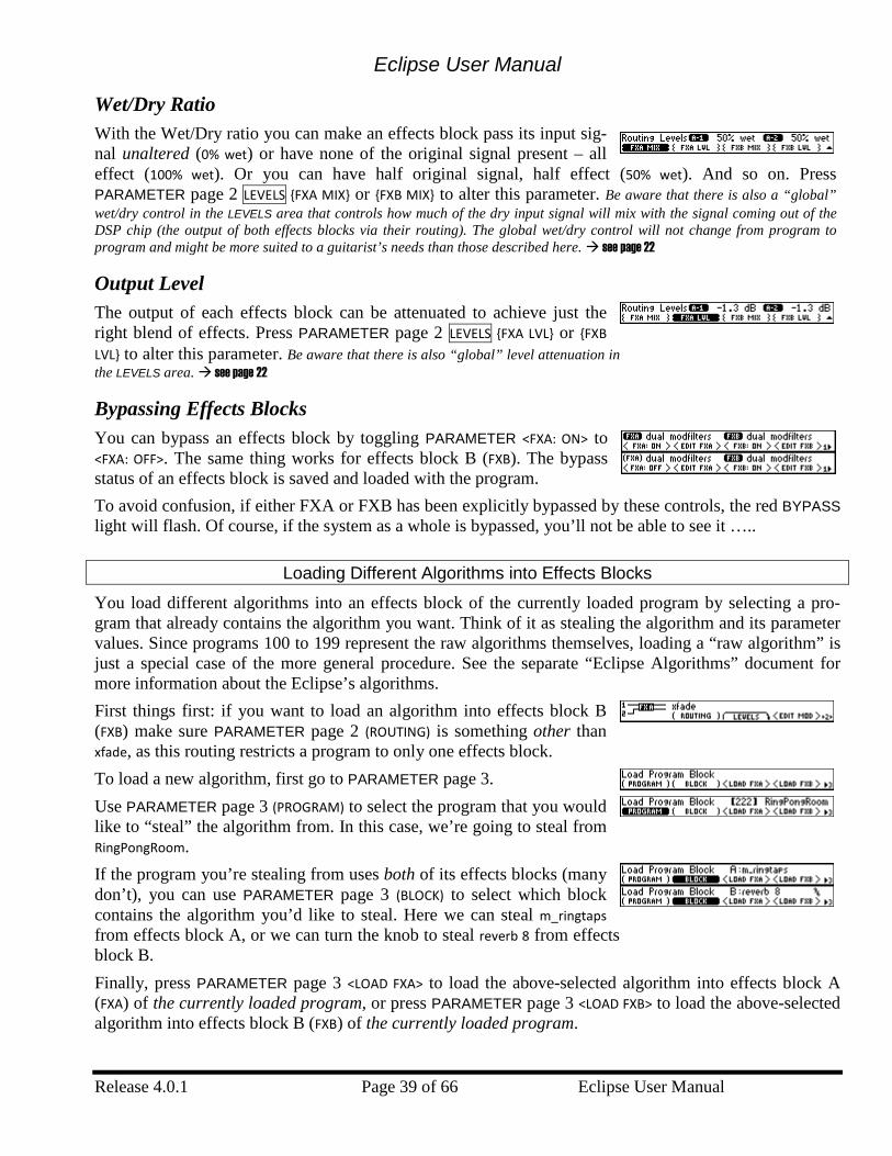
Eclipse User Manual
Release 4.0.1 Page 39 of 66 Eclipse User Manual
Wet/Dry Ratio With the Wet/Dry ratio you can make an effects block pass its input sig-nal unaltered (0% wet) or have none of the original signal present – all effect (100% wet). Or you can have half original signal, half effect (50% wet). And so on. Press PARAMETER page 2 LEVELS {FXA MIX} or {FXB MIX} to alter this parameter. Be aware that there is also a “global” wet/dry control in the LEVELS area that controls how much of the dry input signal will mix with the signal coming out of the DSP chip (the output of both effects blocks via their routing). The global wet/dry control will not change from program to program and might be more suited to a guitarist’s needs than those described here. see page 22
Output Level The output of each effects block can be attenuated to achieve just the right blend of effects. Press PARAMETER page 2 LEVELS {FXA LVL} or {FXB LVL} to alter this parameter. Be aware that there is also “global” level attenuation in the LEVELS area. see page 22
Bypassing Effects Blocks
You can bypass an effects block by toggling PARAMETER <FXA: ON> to <FXA: OFF>. The same thing works for effects block B (FXB). The bypass status of an effects block is saved and loaded with the program. To avoid confusion, if either FXA or FXB has been explicitly bypassed by these controls, the red BYPASS light will flash. Of course, if the system as a whole is bypassed, you’ll not be able to see it …..
Loading Different Algorithms into Effects Blocks
You load different algorithms into an effects block of the currently loaded program by selecting a pro-gram that already contains the algorithm you want. Think of it as stealing the algorithm and its parameter values. Since programs 100 to 199 represent the raw algorithms themselves, loading a “raw algorithm” is just a special case of the more general procedure. See the separate “Eclipse Algorithms” document for more information about the Eclipse’s algorithms. First things first: if you want to load an algorithm into effects block B (FXB) make sure PARAMETER page 2 (ROUTING) is something other than xfade, as this routing restricts a program to only one effects block. To load a new algorithm, first go to PARAMETER page 3. Use PARAMETER page 3 (PROGRAM) to select the program that you would like to “steal” the algorithm from. In this case, we’re going to steal from RingPongRoom. If the program you’re stealing from uses both of its effects blocks (many don’t), you can use PARAMETER page 3 (BLOCK) to select which block contains the algorithm you’d like to steal. Here we can steal m_ringtaps from effects block A, or we can turn the knob to steal reverb 8 from effects block B. Finally, press PARAMETER page 3 <LOAD FXA> to load the above-selected algorithm into effects block A (FXA) of the currently loaded program, or press PARAMETER page 3 <LOAD FXB> to load the above-selected algorithm into effects block B (FXB) of the currently loaded program.
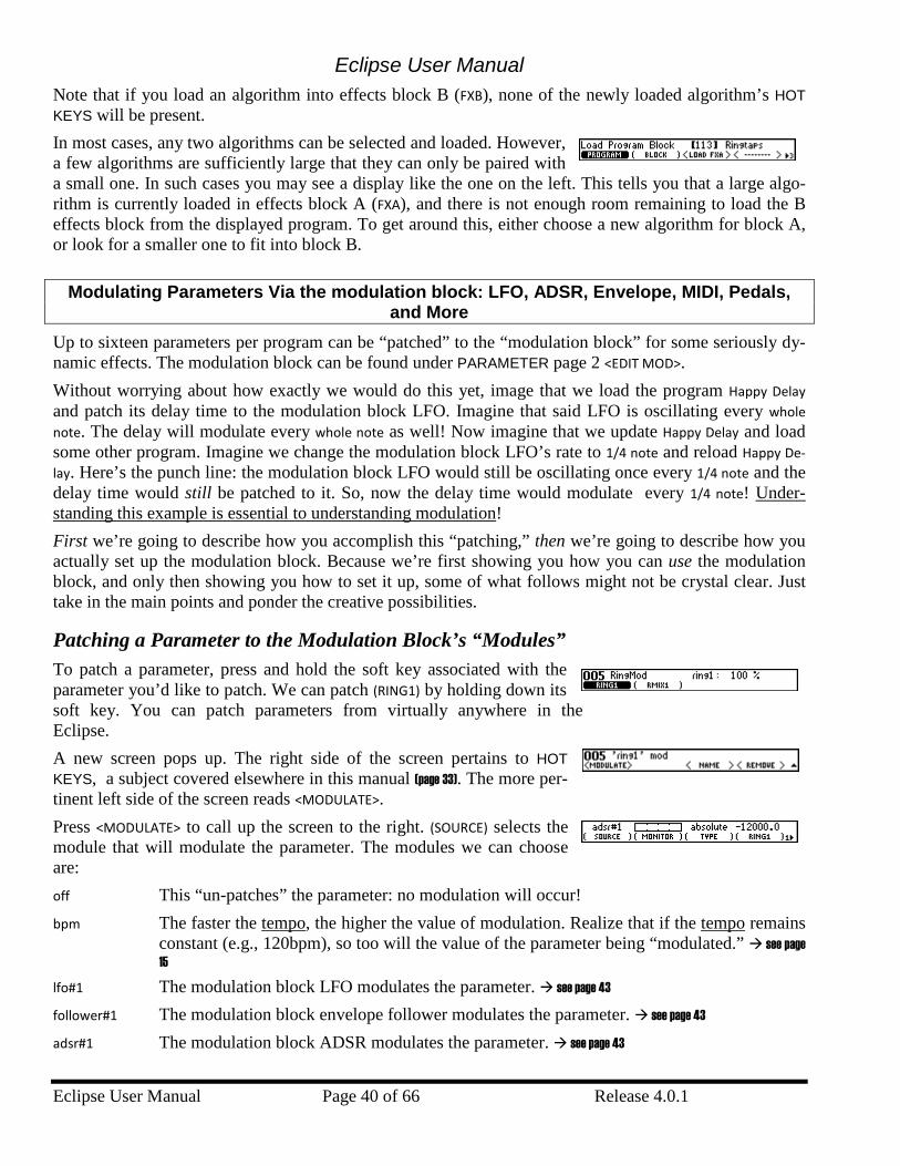
Eclipse User Manual
Eclipse User Manual Page 40 of 66 Release 4.0.1
Note that if you load an algorithm into effects block B (FXB), none of the newly loaded algorithm’s HOT KEYS will be present. In most cases, any two algorithms can be selected and loaded. However, a few algorithms are sufficiently large that they can only be paired with a small one. In such cases you may see a display like the one on the left. This tells you that a large algo-rithm is currently loaded in effects block A (FXA), and there is not enough room remaining to load the B effects block from the displayed program. To get around this, either choose a new algorithm for block A, or look for a smaller one to fit into block B.
Modulating Parameters Via the modulation block: LFO, ADSR, Envelope, MIDI, Pedals, and More
Up to sixteen parameters per program can be “patched” to the “modulation block” for some seriously dy-namic effects. The modulation block can be found under PARAMETER page 2 <EDIT MOD>. Without worrying about how exactly we would do this yet, image that we load the program Happy Delay and patch its delay time to the modulation block LFO. Imagine that said LFO is oscillating every whole note. The delay will modulate every whole note as well! Now imagine that we update Happy Delay and load some other program. Imagine we change the modulation block LFO’s rate to 1/4 note and reload Happy De-lay. Here’s the punch line: the modulation block LFO would still be oscillating once every 1/4 note and the delay time would still be patched to it. So, now the delay time would modulate every 1/4 note! Under-standing this example is essential to understanding modulation! First we’re going to describe how you accomplish this “patching,” then we’re going to describe how you actually set up the modulation block. Because we’re first showing you how you can use the modulation block, and only then showing you how to set it up, some of what follows might not be crystal clear. Just take in the main points and ponder the creative possibilities.
Patching a Parameter to the Modulation Block’s “Modules” To patch a parameter, press and hold the soft key associated with the parameter you’d like to patch. We can patch (RING1) by holding down its soft key. You can patch parameters from virtually anywhere in the Eclipse. A new screen pops up. The right side of the screen pertains to HOT KEYS, a subject covered elsewhere in this manual (page 33). The more per-tinent left side of the screen reads <MODULATE>. Press <MODULATE> to call up the screen to the right. (SOURCE) selects the module that will modulate the parameter. The modules we can choose are: off This “un-patches” the parameter: no modulation will occur! bpm The faster the tempo, the higher the value of modulation. Realize that if the tempo remains
constant (e.g., 120bpm), so too will the value of the parameter being “modulated.” see page 15
lfo#1 The modulation block LFO modulates the parameter. see page 43 follower#1 The modulation block envelope follower modulates the parameter. see page 43 adsr#1 The modulation block ADSR modulates the parameter. see page 43
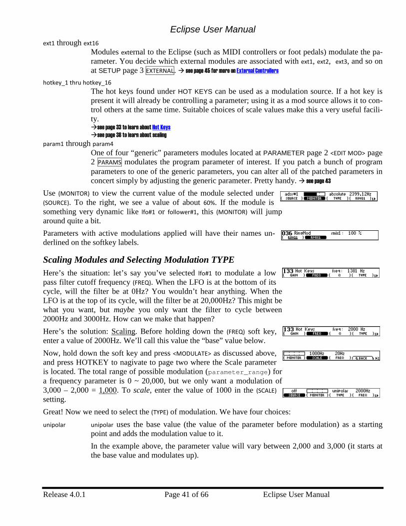
Eclipse User Manual
Release 4.0.1 Page 41 of 66 Eclipse User Manual
ext1 through ext16 Modules external to the Eclipse (such as MIDI controllers or foot pedals) modulate the pa-rameter. You decide which external modules are associated with ext1, ext2, ext3, and so on at SETUP page 3 EXTERNAL. see page 45 for more on External Controllers
hotkey_1 thru hotkey_16 The hot keys found under HOT KEYS can be used as a modulation source. If a hot key is
present it will already be controlling a parameter; using it as a mod source allows it to con-trol others at the same time. Suitable choices of scale values make this a very useful facili-ty.
see page 33 to learn about Hot Keys see page 38 to learn about scaling
param1 through param4 One of four “generic” parameters modules located at PARAMETER page 2 <EDIT MOD> page 2 PARAMS modulates the program parameter of interest. If you patch a bunch of program parameters to one of the generic parameters, you can alter all of the patched parameters in concert simply by adjusting the generic parameter. Pretty handy. see page 43
Use (MONITOR) to view the current value of the module selected under (SOURCE). To the right, we see a value of about 60%. If the module is something very dynamic like lfo#1 or follower#1, this (MONITOR) will jump around quite a bit. Parameters with active modulations applied will have their names un-derlined on the softkey labels.
Scaling Modules and Selecting Modulation TYPE Here’s the situation: let’s say you’ve selected lfo#1 to modulate a low pass filter cutoff frequency (FREQ). When the LFO is at the bottom of its cycle, will the filter be at 0Hz? You wouldn’t hear anything. When the LFO is at the top of its cycle, will the filter be at 20,000Hz? This might be what you want, but maybe you only want the filter to cycle between 2000Hz and 3000Hz. How can we make that happen? Here’s the solution: Scaling. Before holding down the (FREQ) soft key, enter a value of 2000Hz. We’ll call this value the “base” value below. Now, hold down the soft key and press <MODULATE> as discussed above, and press HOTKEY to nagivate to page two where the Scale parameter is located. The total range of possible modulation (parameter_range) for a frequency parameter is 0 ~ 20,000, but we only want a modulation of 3,000 – 2,000 = 1,000. To scale, enter the value of 1000 in the (SCALE) setting. Great! Now we need to select the (TYPE) of modulation. We have four choices: unipolar unipolar uses the base value (the value of the parameter before modulation) as a starting
point and adds the modulation value to it. In the example above, the parameter value will vary between 2,000 and 3,000 (it starts at the base value and modulates up).
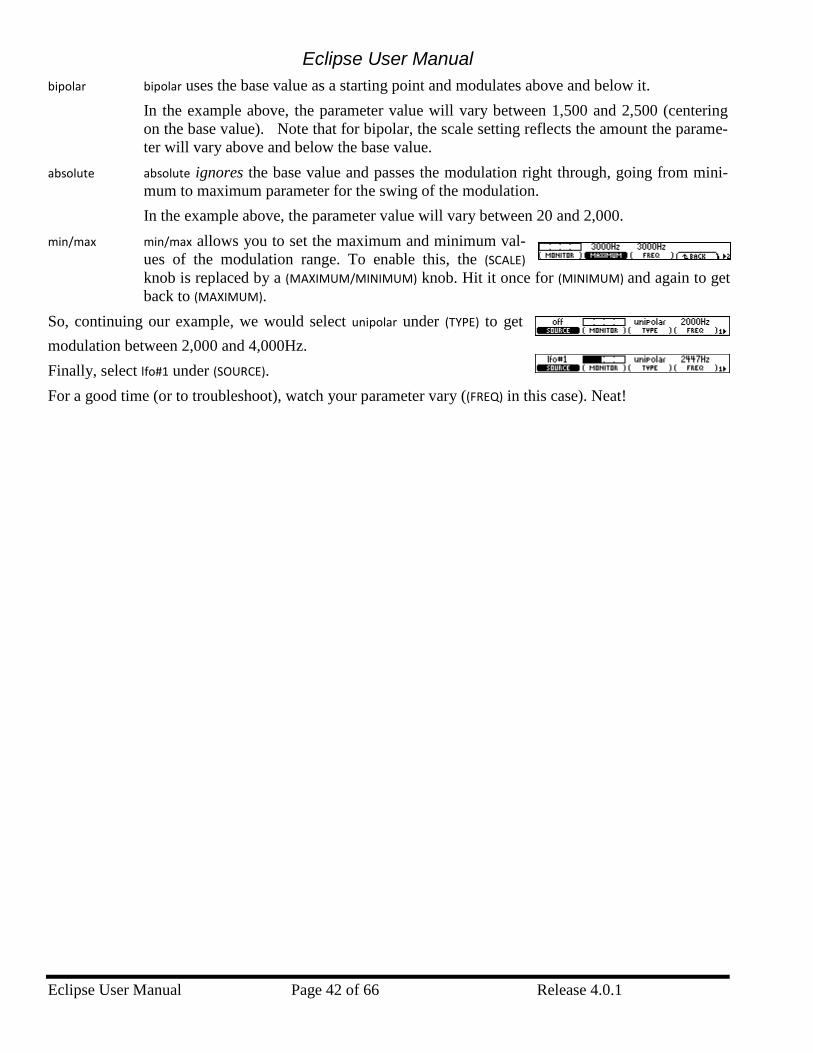
Eclipse User Manual
Eclipse User Manual Page 42 of 66 Release 4.0.1
bipolar bipolar uses the base value as a starting point and modulates above and below it. In the example above, the parameter value will vary between 1,500 and 2,500 (centering on the base value). Note that for bipolar, the scale setting reflects the amount the parame-ter will vary above and below the base value.
absolute absolute ignores the base value and passes the modulation right through, going from mini-mum to maximum parameter for the swing of the modulation. In the example above, the parameter value will vary between 20 and 2,000.
min/max min/max allows you to set the maximum and minimum val-ues of the modulation range. To enable this, the (SCALE) knob is replaced by a (MAXIMUM/MINIMUM) knob. Hit it once for (MINIMUM) and again to get back to (MAXIMUM).
So, continuing our example, we would select unipolar under (TYPE) to get modulation between 2,000 and 4,000Hz. Finally, select lfo#1 under (SOURCE). For a good time (or to troubleshoot), watch your parameter vary ((FREQ) in this case). Neat!
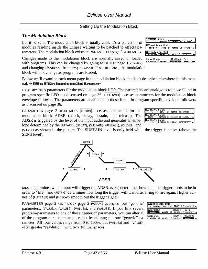
Eclipse User Manual
Release 4.0.1 Page 43 of 66 Eclipse User Manual
Setting Up the Modulation Block
The Modulation Block Let it be said: The modulation block is totally cool. It’s a collection of modules residing inside the Eclipse waiting to be patched to effects pa-rameters. The modulation block exists at PARAMETER page 2 <EDIT MOD>. Changes made to the modulation block are normally saved or loaded with programs. This can be changed by going to SETUP page 1 <modes> and changing (ModBlock) from Prog to Global. If set to Global, the modulation block will not change as programs are loaded. Below we’ll examine each menu page in the modulation block that isn’t described elsewhere in this man-ual. TTIME and RETRIG are discussed on pages 35 and 36, respectively LFO#1 accesses parameters for the modulation block LFO. The parameters are analogous to those found in program-specific LFOs as discussed on page 36. FOLLOW#1 accesses parameters for the modulation block envelope follower. The parameters are analogous to those found in program-specific envelope followers as discussed on page 36. PARAMETER page 2 <EDIT MOD> ADSR#1 accesses parameters for the modulation block ADSR (attack, decay, sustain, and release). The ADSR is triggered by the level of the input audio and generates an enve-lope determined by the (ATTACK), (DECAY), (SUSTAIN), (RELEASE), (DLEVEL), and (SLEVEL) as shown in the picture. The SUSTAIN level is only held while the trigger is active (above the SENS level).
(ADSR) determines which input will trigger the ADSR. (SENS) determines how loud the trigger needs to be in order to “fire,” and (RETRIG) determines how long the trigger will wait after firing to fire again. Higher val-ues of (F ATTACK) and (F DECAY) smooth out the trigger signal. PARAMETER page 2 <EDIT MOD> page 2 PARAMS accesses four “generic” parameters: (VALUE1), (VALUE2), (VALUE3), and (VALUE4). If you link several program-parameters to one of these “generic” parameters, you can alter all of the program-parameters at once just by altering the one “generic” pa-rameter. All four values range from 0 to 100%, but (VALUE3) and (VALUE4) offer greater “resolution” with two decimal spaces.
Eclipse User Manual
Eclipse User Manual Page 44 of 66 Release 4.0.1
More on modulation
On Eclipse, almost everything can be modulated, and almost everything can be a modulation source. For example, a hot key can be used to modulate other parameters, but it can itself be modulated. A powerful demonstration of this is to load or create a dual-effect program. Add a hotkey to control the Wet/Dry mix of FXA, and use this as a modulation source for the Wet/Dry mix of FxB. Set the scale of this modulation to -100%. Then you have a single knob that will blend the amount of each effect, giving a ‘morph’-like control. Then, modulate this knob with, say, an LFO... It is important to note the distinction between modulating a hot key and modulating the parameter to which the hot keys is assigned – this is not the same thing. see page 33 to learn about Hot Keys
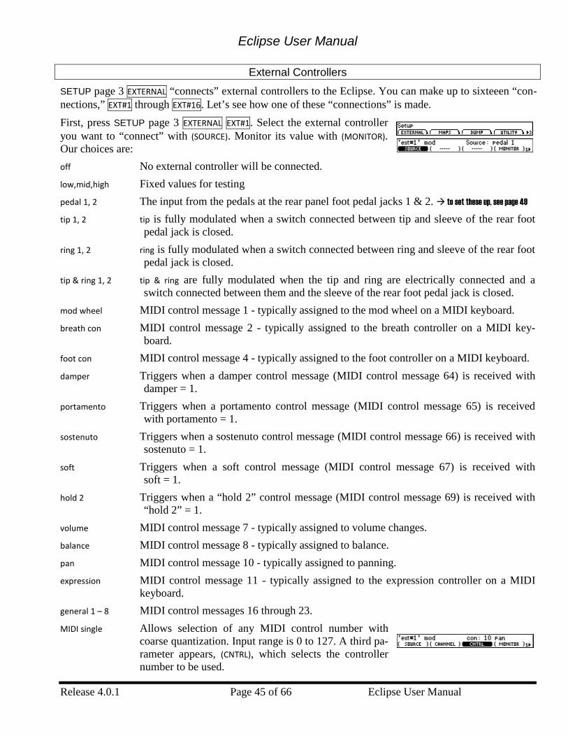
Eclipse User Manual
Release 4.0.1 Page 45 of 66 Eclipse User Manual
External Controllers
SETUP page 3 EXTERNAL “connects” external controllers to the Eclipse. You can make up to sixteeen “con-nections,” EXT#1 through EXT#16. Let’s see how one of these “connections” is made. First, press SETUP page 3 EXTERNAL EXT#1. Select the external controller you want to “connect” with (SOURCE). Monitor its value with (MONITOR). Our choices are: off No external controller will be connected. low,mid,high Fixed values for testing pedal 1, 2 The input from the pedals at the rear panel foot pedal jacks 1 & 2. to set these up, see page 49 tip 1, 2 tip is fully modulated when a switch connected between tip and sleeve of the rear foot
pedal jack is closed. ring 1, 2 ring is fully modulated when a switch connected between ring and sleeve of the rear foot
pedal jack is closed. tip & ring 1, 2 tip & ring are fully modulated when the tip and ring are electrically connected and a
switch connected between them and the sleeve of the rear foot pedal jack is closed. mod wheel MIDI control message 1 - typically assigned to the mod wheel on a MIDI keyboard. breath con MIDI control message 2 - typically assigned to the breath controller on a MIDI key-
board. foot con MIDI control message 4 - typically assigned to the foot controller on a MIDI keyboard. damper Triggers when a damper control message (MIDI control message 64) is received with
damper = 1. portamento Triggers when a portamento control message (MIDI control message 65) is received
with portamento = 1. sostenuto Triggers when a sostenuto control message (MIDI control message 66) is received with
sostenuto = 1. soft Triggers when a soft control message (MIDI control message 67) is received with
soft = 1. hold 2 Triggers when a “hold 2” control message (MIDI control message 69) is received with
“hold 2” = 1. volume MIDI control message 7 - typically assigned to volume changes. balance MIDI control message 8 - typically assigned to balance. pan MIDI control message 10 - typically assigned to panning. expression MIDI control message 11 - typically assigned to the expression controller on a MIDI
keyboard. general 1 – 8 MIDI control messages 16 through 23. MIDI single Allows selection of any MIDI control number with
coarse quantization. Input range is 0 to 127. A third pa-rameter appears, (CNTRL), which selects the controller number to be used.
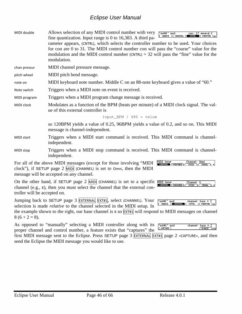
Eclipse User Manual
Eclipse User Manual Page 46 of 66 Release 4.0.1
MIDI double Allows selection of any MIDI control number with very fine quantization. Input range is 0 to 16,383. A third pa-rameter appears, (CNTRL), which selects the controller number to be used. Your choices for con are 0 to 31. The MIDI control number con will pass the “coarse” value for the modulation and the MIDI control number (CNTRL) + 32 will pass the “fine” value for the modulation.
chan pressur MIDI channel pressure message. pitch wheel MIDI pitch bend message. note on MIDI keyboard note number. Middle C on an 88-note keyboard gives a value of “60.” Note switch Triggers when a MIDI note on event is received. MIDI program Triggers when a MIDI program change message is received. MIDI clock Modulates as a function of the BPM (beats per minute) of a MIDI clock signal. The val-
ue of this external controller is input_BPM / 480 = value
so 120BPM yields a value of 0.25, 96BPM yields a value of 0.2, and so on. This MIDI message is channel-independent.
MIDI start Triggers when a MIDI start command is received. This MIDI command is channel-independent.
MIDI stop Triggers when a MIDI stop command is received. This MIDI command is channel-independent.
For all of the above MIDI messages (except for those involving “MIDI clock”), if SETUP page 2 MIDI (CHANNEL) is set to Omni, then the MIDI message will be accepted on any channel. On the other hand, if SETUP page 2 MIDI (CHANNEL) is set to a specific channel (e.g., 6), then you must select the channel that the external con-troller will be accepted on. Jumping back to SETUP page 3 EXTERNAL EXT#1, select (CHANNEL). Your selection is made relative to the channel selected in the MIDI setup. In the example shown to the right, our base channel is 6 so EXT#1 will respond to MIDI messages on channel 8 (6 + 2 = 8). As opposed to “manually” selecting a MIDI controller along with its proper channel and control number, a feature exists that “captures” the first MIDI message sent to the Eclipse. Press SETUP page 3 EXTERNAL EXT#1 page 2 <CAPTURE>, and then send the Eclipse the MIDI message you would like to use.
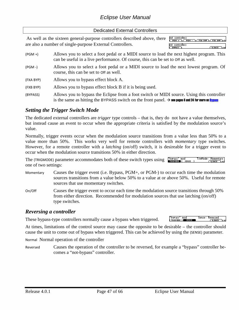
Eclipse User Manual
Release 4.0.1 Page 47 of 66 Eclipse User Manual
Dedicated External Controllers
As well as the sixteen general-purpose controllers described above, there are also a number of single-purpose External Controllers.
(PGM +) Allows you to select a foot pedal or a MIDI source to load the next highest program. This can be useful in a live performance. Of course, this can be set to Off as well.
(PGM -) Allows you to select a foot pedal or a MIDI source to load the next lowest program. Of course, this can be set to Off as well.
(FXA BYP) Allows you to bypass effect block A. (FXB BYP) Allows you to bypass effect block B if it is being used. (BYPASS) Allows you to bypass the Eclipse from a foot switch or MIDI source. Using this controller
is the same as hitting the BYPASS switch on the front panel. see pages 8 and 24 for more on Bypass
Setting the Trigger Switch Mode The dedicated external controllers are trigger type controls – that is, they do not have a value themselves, but instead cause an event to occur when the appropriate criteria is satisfied by the modulation source’s value. Normally, trigger events occur when the modulation source transitions from a value less than 50% to a value more than 50%. This works very well for remote controllers with momentary type switches. However, for a remote controller with a latching (on/off) switch, it is desireable for a trigger event to occur when the modulation source transitions 50% in either direction. The (TRIGMODE) parameter accommodates both of these switch types using one of two settings: Momentary Causes the trigger event (i.e. Bypass, PGM+, or PGM-) to occur each time the modulation
sources transitions from a value below 50% to a value at or above 50%. Useful for remote sources that use momentary switches.
On/Off Causes the trigger event to occur each time the modulation source transitions through 50% from either direction. Recommended for modulation sources that use latching (on/off) type switches.
Reversing a controller These bypass-type controllers normally cause a bypass when triggered. At times, limitations of the control source may cause the opposite to be desirable – the controller should cause the unit to come out of bypass when triggered. This can be achieved by using the (SENSE) parameter. Normal Normal operation of the controller Reversed Causes the operation of the controller to be reversed, for example a “bypass” controller be-
comes a “not-bypass” controller.
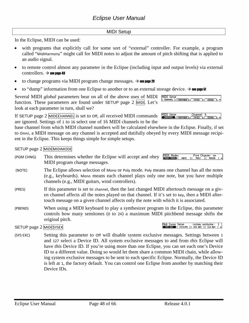
Eclipse User Manual
Eclipse User Manual Page 48 of 66 Release 4.0.1
MIDI Setup
In the Eclipse, MIDI can be used: • with programs that explicitly call for some sort of “external” controller. For example, a program
called “MidiHarmony” might call for MIDI notes to adjust the amount of pitch shifting that is applied to an audio signal.
• to remote control almost any parameter in the Eclipse (including input and output levels) via external controllers. see page 40
• to change programs via MIDI program change messages. see page 29 • to “dump” information from one Eclipse to another or to an external storage device. see page 51 Several MIDI global parameters bear on all of the above uses of MIDI function. These parameters are found under SETUP page 2 MIDI. Let’s look at each parameter in turn, shall we? If SETUP page 2 MIDI CHANNEL is set to Off, all received MIDI commands are ignored. Settings of 1 to 16 select one of 16 MIDI channels to be the base channel from which MIDI channel numbers will be calculated elsewhere in the Eclipse. Finally, if set to Omni, a MIDI message on any channel is accepted and dutifully obeyed by every MIDI message recipi-ent in the Eclipse. This keeps things simple for simple setups.
SETUP page 2 MIDI MIDIMODE (PGM CHNG) This determines whether the Eclipse will accept and obey
MIDI program change messages. (NOTE) The Eclipse allows selection of Mono or Poly mode. Poly means one channel has all the notes
(e.g., keyboards). Mono means each channel plays only one note, but you have multiple channels (e.g., MIDI guitars, wind controllers).
(PRES) If this parameter is set to channel, then the last changed MIDI aftertouch message on a giv-en channel affects all the notes played on that channel. If it’s set to key, then a MIDI after-touch message on a given channel affects only the note with which it is associated.
(PBEND) When using a MIDI keyboard to play a synthesizer program in the Eclipse, this parameter controls how many semitones (0 to 24) a maximum MIDI pitchbend message shifts the original pitch.
SETUP page 2 MIDI SYSEX (SYS EXC) Setting this parameter to Off will disable system exclusive messages. Settings between 1
and 127 select a Device ID. All system exclusive messages to and from this Eclipse will have this Device ID. If you’re using more than one Eclipse, you can set each one’s Device ID to a different value. Doing so would let them share a common MIDI chain, while allow-ing system exclusive messages to be sent to each specific Eclipse. Normally, the Device ID is left at 1, the factory default. You can control one Eclipse from another by matching their Device IDs.
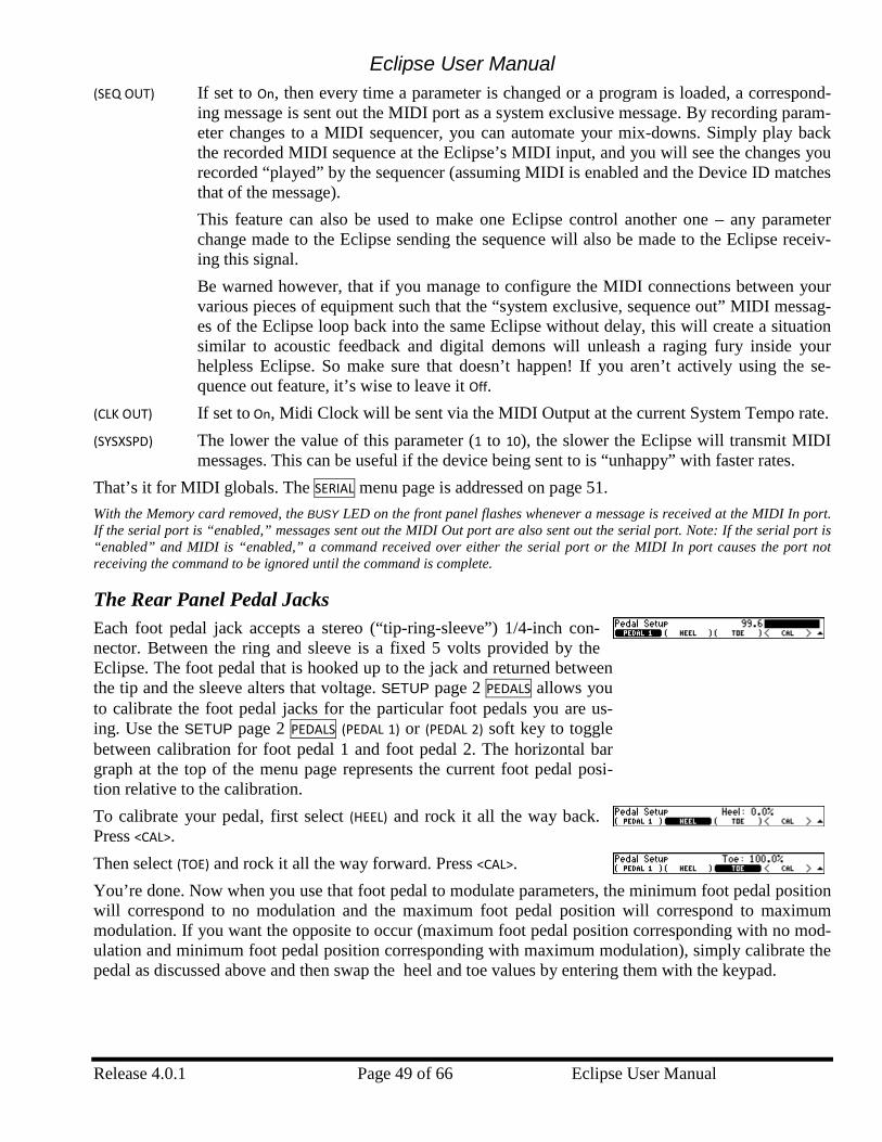
Eclipse User Manual
Release 4.0.1 Page 49 of 66 Eclipse User Manual
(SEQ OUT) If set to On, then every time a parameter is changed or a program is loaded, a correspond-ing message is sent out the MIDI port as a system exclusive message. By recording param-eter changes to a MIDI sequencer, you can automate your mix-downs. Simply play back the recorded MIDI sequence at the Eclipse’s MIDI input, and you will see the changes you recorded “played” by the sequencer (assuming MIDI is enabled and the Device ID matches that of the message). This feature can also be used to make one Eclipse control another one – any parameter change made to the Eclipse sending the sequence will also be made to the Eclipse receiv-ing this signal. Be warned however, that if you manage to configure the MIDI connections between your various pieces of equipment such that the “system exclusive, sequence out” MIDI messag-es of the Eclipse loop back into the same Eclipse without delay, this will create a situation similar to acoustic feedback and digital demons will unleash a raging fury inside your helpless Eclipse. So make sure that doesn’t happen! If you aren’t actively using the se-quence out feature, it’s wise to leave it Off.
(CLK OUT) If set to On, Midi Clock will be sent via the MIDI Output at the current System Tempo rate. (SYSXSPD) The lower the value of this parameter (1 to 10), the slower the Eclipse will transmit MIDI
messages. This can be useful if the device being sent to is “unhappy” with faster rates. That’s it for MIDI globals. The SERIAL menu page is addressed on page 51. With the Memory card removed, the BUSY LED on the front panel flashes whenever a message is received at the MIDI In port. If the serial port is “enabled,” messages sent out the MIDI Out port are also sent out the serial port. Note: If the serial port is “enabled” and MIDI is “enabled,” a command received over either the serial port or the MIDI In port causes the port not receiving the command to be ignored until the command is complete.
The Rear Panel Pedal Jacks Each foot pedal jack accepts a stereo (“tip-ring-sleeve”) 1/4-inch con-nector. Between the ring and sleeve is a fixed 5 volts provided by the Eclipse. The foot pedal that is hooked up to the jack and returned between the tip and the sleeve alters that voltage. SETUP page 2 PEDALS allows you to calibrate the foot pedal jacks for the particular foot pedals you are us-ing. Use the SETUP page 2 PEDALS (PEDAL 1) or (PEDAL 2) soft key to toggle between calibration for foot pedal 1 and foot pedal 2. The horizontal bar graph at the top of the menu page represents the current foot pedal posi-tion relative to the calibration. To calibrate your pedal, first select (HEEL) and rock it all the way back. Press <CAL>. Then select (TOE) and rock it all the way forward. Press <CAL>. You’re done. Now when you use that foot pedal to modulate parameters, the minimum foot pedal position will correspond to no modulation and the maximum foot pedal position will correspond to maximum modulation. If you want the opposite to occur (maximum foot pedal position corresponding with no mod-ulation and minimum foot pedal position corresponding with maximum modulation), simply calibrate the pedal as discussed above and then swap the heel and toe values by entering them with the keypad.
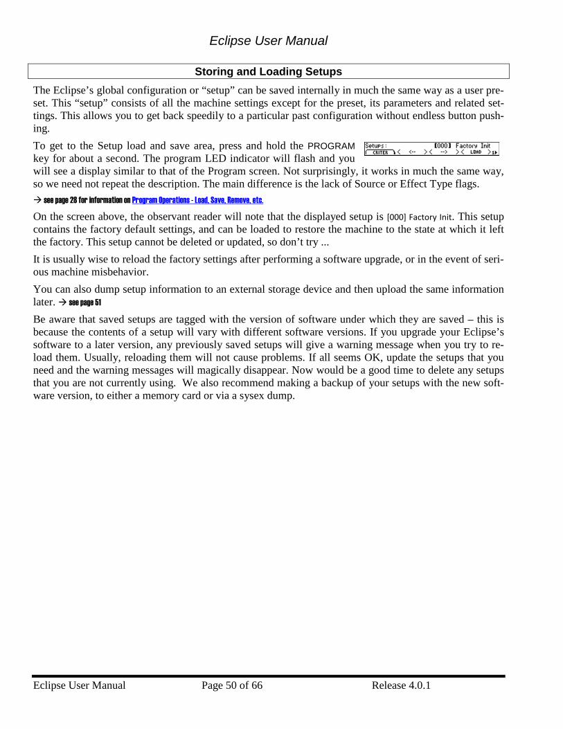
Eclipse User Manual
Eclipse User Manual Page 50 of 66 Release 4.0.1
Storing and Loading Setups The Eclipse’s global configuration or “setup” can be saved internally in much the same way as a user pre-set. This “setup” consists of all the machine settings except for the preset, its parameters and related set-tings. This allows you to get back speedily to a particular past configuration without endless button push-ing. To get to the Setup load and save area, press and hold the PROGRAM key for about a second. The program LED indicator will flash and you will see a display similar to that of the Program screen. Not surprisingly, it works in much the same way, so we need not repeat the description. The main difference is the lack of Source or Effect Type flags. see page 28 for information on Program Operations - Load, Save, Remove, etc. On the screen above, the observant reader will note that the displayed setup is [000] Factory Init. This setup contains the factory default settings, and can be loaded to restore the machine to the state at which it left the factory. This setup cannot be deleted or updated, so don’t try ... It is usually wise to reload the factory settings after performing a software upgrade, or in the event of seri-ous machine misbehavior. You can also dump setup information to an external storage device and then upload the same information later. see page 51
Be aware that saved setups are tagged with the version of software under which they are saved – this is because the contents of a setup will vary with different software versions. If you upgrade your Eclipse’s software to a later version, any previously saved setups will give a warning message when you try to re-load them. Usually, reloading them will not cause problems. If all seems OK, update the setups that you need and the warning messages will magically disappear. Now would be a good time to delete any setups that you are not currently using. We also recommend making a backup of your setups with the new soft-ware version, to either a memory card or via a sysex dump.
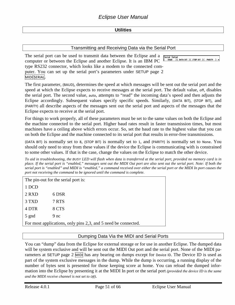
Eclipse User Manual
Release 4.0.1 Page 51 of 66 Eclipse User Manual
Utilities
Transmitting and Receiving Data via the Serial Port
The serial port can be used to transmit data between the Eclipse and a computer or between the Eclipse and another Eclipse. It is an IBM PC type RS232 connector, which looks like a modem to the connected com-puter. You can set up the serial port’s parameters under SETUP page 2 MIDI SERIAL. The first parameter, (BAUD), determines the speed at which messages will be sent out the serial port and the speed at which the Eclipse expects to receive messages at the serial port. The default value, off, disables the serial port. The second value, auto, attempts to “read” the incoming data’s speed and then adjusts the Eclipse accordingly. Subsequent values specify specific speeds. Similarly, (DATA BIT), (STOP BIT), and (PARITY) all describe aspects of the messages sent out the serial port and aspects of the messages that the Eclipse expects to receive at the serial port. For things to work properly, all of these parameters must be set to the same values on both the Eclipse and the machine connected to the serial port. Higher baud rates result in faster transmission times, but most machines have a ceiling above which errors occur. So, set the baud rate to the highest value that you can on both the Eclipse and the machine connected to its serial port that results in error-free transmissions. (DATA BIT) is normally set to 8, (STOP BIT) is normally set to 1, and (PARITY) is normally set to None. You should only need to stray from these values if the device the Eclipse is communicating with is constrained to some other values. If that is the case, change the values on the Eclipse to match the other device. To aid in troubleshooting, the BUSY LED will flash when data is transferred at the serial port, provided no memory card is in place. If the serial port is “enabled,” messages sent out the MIDI Out port are also sent out the serial port. Note: If both the serial port is “enabled” and MIDI is “enabled,” a command received over either the serial port or the MIDI In port causes the port not receiving the command to be ignored until the command is complete.
The pin-out for the serial port is: 1 DCD 2 RXD 6 DSR 3 TXD 7 RTS 4 DTR 8 CTS 5 gnd 9 nc For most applications, only pins 2,3, and 5 need be connected.
Dumping Data Via the MIDI and Serial Ports
You can “dump” data from the Eclipse for external storage or for use in another Eclipse. The dumped data will be system exclusive and will be sent out the MIDI Out port and the serial port. None of the MIDI pa-rameters at SETUP page 2 MIDI has any bearing on dumps except for Device ID. The Device ID is used as part of the system exclusive messages in the dump. While the dump is occurring, a running display of the number of bytes sent is presented for those keeping score at home. You can reload the dumped infor-mation into the Eclipse by presenting it at the MIDI In port or the serial port (provided the device ID is the same and the MIDI receive channel is not set to Off).
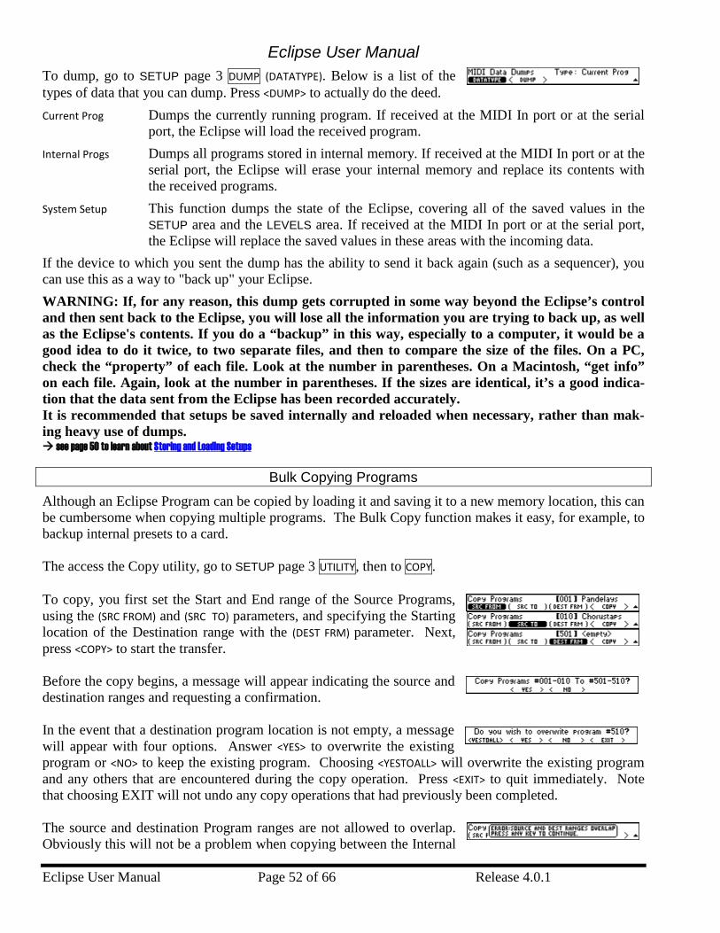
Eclipse User Manual
Eclipse User Manual Page 52 of 66 Release 4.0.1
To dump, go to SETUP page 3 DUMP (DATATYPE). Below is a list of the types of data that you can dump. Press <DUMP> to actually do the deed. Current Prog Dumps the currently running program. If received at the MIDI In port or at the serial
port, the Eclipse will load the received program. Internal Progs Dumps all programs stored in internal memory. If received at the MIDI In port or at the
serial port, the Eclipse will erase your internal memory and replace its contents with the received programs.
System Setup This function dumps the state of the Eclipse, covering all of the saved values in the SETUP area and the LEVELS area. If received at the MIDI In port or at the serial port, the Eclipse will replace the saved values in these areas with the incoming data.
If the device to which you sent the dump has the ability to send it back again (such as a sequencer), you can use this as a way to "back up" your Eclipse. WARNING: If, for any reason, this dump gets corrupted in some way beyond the Eclipse’s control and then sent back to the Eclipse, you will lose all the information you are trying to back up, as well as the Eclipse's contents. If you do a “backup” in this way, especially to a computer, it would be a good idea to do it twice, to two separate files, and then to compare the size of the files. On a PC, check the “property” of each file. Look at the number in parentheses. On a Macintosh, “get info” on each file. Again, look at the number in parentheses. If the sizes are identical, it’s a good indica-tion that the data sent from the Eclipse has been recorded accurately. It is recommended that setups be saved internally and reloaded when necessary, rather than mak-ing heavy use of dumps. see page 50 to learn about Storing and Loading Setups
Bulk Copying Programs
Although an Eclipse Program can be copied by loading it and saving it to a new memory location, this can be cumbersome when copying multiple programs. The Bulk Copy function makes it easy, for example, to backup internal presets to a card. The access the Copy utility, go to SETUP page 3 UTILITY, then to COPY. To copy, you first set the Start and End range of the Source Programs, using the (SRC FROM) and (SRC TO) parameters, and specifying the Starting location of the Destination range with the (DEST FRM) parameter. Next, press <COPY> to start the transfer. Before the copy begins, a message will appear indicating the source and destination ranges and requesting a confirmation. In the event that a destination program location is not empty, a message will appear with four options. Answer <YES> to overwrite the existing program or <NO> to keep the existing program. Choosing <YESTOALL> will overwrite the existing program and any others that are encountered during the copy operation. Press <EXIT> to quit immediately. Note that choosing EXIT will not undo any copy operations that had previously been completed. The source and destination Program ranges are not allowed to overlap. Obviously this will not be a problem when copying between the Internal
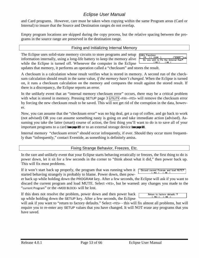
Eclipse User Manual
Release 4.0.1 Page 53 of 66 Eclipse User Manual
and Card programs. However, care must be taken when copying within the same Program areas (Card or Internal) to insure that the Source and Destination ranges do not overlap. Empty program locations are skipped during the copy process, but the relative spacing between the pro-grams in the source range are preserved in the destination range.
Fixing and Initializing Internal Memory
The Eclipse uses solid-state memory circuits to store programs and setup information internally, using a long-life battery to keep the memory alive while the Eclipse is turned off. Whenever the computer in the Eclipse updates that memory, it performs an operation called a “checksum” and stores the result. A checksum is a calculation whose result verifies what is stored in memory. A second run of the check-sum calculation should result in the same value, if the memory hasn’t changed. When the Eclipse is turned on, it runs a checksum calculation on the memory and compares the result against the stored result. If there is a discrepancy, the Eclipse reports an error. In the unlikely event that an “internal memory checksum error” occurs, there may be a critical problem with what is stored in memory. Pressing SETUP page 3 UTILITY <FIX> <YES> will remove the checksum error by forcing the new checksum result to be saved. This will not get rid of the corruption in the data, howev-er. Now, you can assume that the “checksum error” was no big deal, get a cup of coffee, and go back to work (not advised) OR you can assume something nasty is going on and take immediate action (advised). As-suming you take the latter (smart) course of action, the first thing you’ll want to do is to save all of your important programs to a card (see page 32) or to an external storage device (see page 51). Internal memory “checksum errors” should occur infrequently, if ever. Should they occur more frequent-ly than “infrequently,” contact Eventide, as something is definitely amiss.
Fixing Strange Behavior, Freezes, Etc.
In the rare and unlikely event that your Eclipse starts behaving erratically or freezes, the first thing to do is power down, let it sit for a few seconds in the corner to “think about what it did,” then power back up. This will fix most problems. If it won’t start back up properly, the program that was running when it started behaving strangely is probably to blame. Power down, then pow-er back up while holding down the PROGRAM key. After a few seconds, the Eclipse will ask if you want to discard the current program and load MUTE. Select <YES>, but be warned: any changes you made to the “current Program” or the <MOD BLOCK> will be lost. If this does not resolve the problem, power down and then power back up while holding down the SETUP key. After a few seconds, the Eclipse will ask if you want to “return to factory defaults.” Select <YES> - this will fix almost all problems, but will require you to re-enter any SETUP values that you have changed. It will NOT erase any programs that you have saved.
Eclipse User Manual
Eclipse User Manual Page 54 of 66 Release 4.0.1
If the Eclipse still won’t fly straight, power down and then power back up while holding down the 8 key. After a few seconds, the Eclipse will ask if you want to clear internal memory. Select <YES>, but consider yourself warned: doing so will erase every program between 0 and 99 and change all of the SETUP and LEVELS area parameters back to their factory defaults. As dramatic as this is, it will proba-bly solve your problem. Still having problems? Try reinstalling the operating system as described in the Updating Software sec-tion below. No luck? Your system may have a hardware problem and you should contact Eventide or your dealer for servicing.
Formatting Memory Cards
If you are worried about the contents of the Memory card, you should either dump the contents of the memory card to an external storage device (see page 51) or copy all valuable internal programs to a different Memory Card, copy the faulty Memory Card’s programs to internal memory and then to another Memory card (see page 32). You can also do this with a PC equipped with a suitable CompactFlash card reader. Once you’re sure that there is nothing worthwhile on the card that isn’t saved somewhere else, press SETUP page 3 UTILITY <FORMAT> <YES>. Be advised: doing so will wipe out everything on the card. You might also put a label on the card (using adhesive tape, indelible marker, etc.) indicating that a prob-lem occurred along with the date. Keep track of this kind of problem and make multiple backup copies.
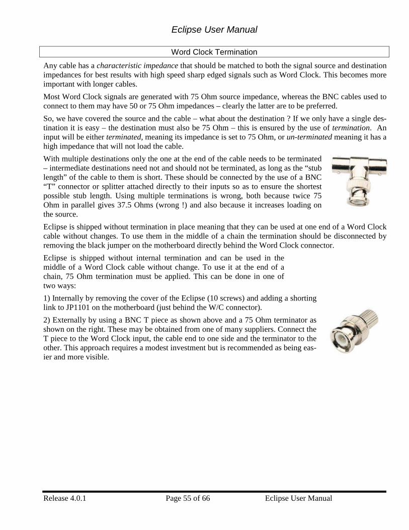
Eclipse User Manual
Release 4.0.1 Page 55 of 66 Eclipse User Manual
Word Clock Termination
Any cable has a characteristic impedance that should be matched to both the signal source and destination impedances for best results with high speed sharp edged signals such as Word Clock. This becomes more important with longer cables. Most Word Clock signals are generated with 75 Ohm source impedance, whereas the BNC cables used to connect to them may have 50 or 75 Ohm impedances – clearly the latter are to be preferred. So, we have covered the source and the cable – what about the destination ? If we only have a single des-tination it is easy – the destination must also be 75 Ohm – this is ensured by the use of termination. An input will be either terminated, meaning its impedance is set to 75 Ohm, or un-terminated meaning it has a high impedance that will not load the cable. With multiple destinations only the one at the end of the cable needs to be terminated – intermediate destinations need not and should not be terminated, as long as the “stub length” of the cable to them is short. These should be connected by the use of a BNC “T” connector or splitter attached directly to their inputs so as to ensure the shortest possible stub length. Using multiple terminations is wrong, both because twice 75 Ohm in parallel gives 37.5 Ohms (wrong !) and also because it increases loading on the source. Eclipse is shipped without termination in place meaning that they can be used at one end of a Word Clock cable without changes. To use them in the middle of a chain the termination should be disconnected by removing the black jumper on the motherboard directly behind the Word Clock connector. Eclipse is shipped without internal termination and can be used in the middle of a Word Clock cable without change. To use it at the end of a chain, 75 Ohm termination must be applied. This can be done in one of two ways: 1) Internally by removing the cover of the Eclipse (10 screws) and adding a shorting link to JP1101 on the motherboard (just behind the W/C connector). 2) Externally by using a BNC T piece as shown above and a 75 Ohm terminator as shown on the right. These may be obtained from one of many suppliers. Connect the T piece to the Word Clock input, the cable end to one side and the terminator to the other. This approach requires a modest investment but is recommended as being eas-ier and more visible.

Eclipse User Manual
Eclipse User Manual Page 56 of 66 Release 4.0.1
Updating Software
The Eclipse Operating System and Factory Presets are field-upgradeable using tools available from Even-tide. These updates can be done with one of two approaches: • an “Upgrade Card” (a specially coded CompactFlash card) • via “OUpdate” (a special Windows Application). The latest Eclipse software and the software tools described below can be obtained via the Eventide Web Site http://www.eventide.com/.
Creating an “Upgrade Card” In order to create an “Upgrade Card,” you must have access to the Eventide website, a PC with a Compact Flash card reader, and an application (e.g., WinZip) that can open and extract zip files. (You may have received an “Upgrade Card” directly from Eventide, in which case you can skip this section.) 1. Download the “Card Upgrade” file from the Eventide website. This file will generally be in the form
of a zip file. 2. Insert a blank, formatted CompactFlash card into the card reader attached to your PC. 3. Unzip the files from the Card Upgrade zip file and copy them to the CompactFlash card.
Updating with a Memory Card 1. Power down the Eclipse. 2. Insert the “Upgrade Card” into the MEMORY CARD slot. 3. While holding down the 1 key, power on the Eclipse. 4. Wait patiently for the programming process to finish. If the programming process is successful, a Pro-
gramming Completed. Cycle Power message will appear. 5. Power down the Eclipse. 6. Remove the “Upgrade Card” and go about your business. The programming process is complete.
Upgrade via the OUpdate Application 1. Using your web browser, download the update application from the Eventide website (e.g.,
“eup2000.exe”), and save it to your computer. 2. Power down the Eclipse. 3. Connect a 9-pin “straight-through” Male-Female serial cable (Radio Shack p/n 26-117) between your
PC serial port and the Eclipse serial port. 4. Start the OUpdate application (double-click on its icon), downloaded in step 1. 5. While holding down the 2 key on the Eclipse, power up the Eclipse. You should see Eventide Software
Update Utility Awaiting Contact. 6. If you have not connected the Eclipse to the COM1 port on your PC, you may need to use the
“OUpdate Setup” button to change the COM port. You should not change the default settings of 115200 baud, 8 data bits, 1 stop bit, and no parity.
7. press the Send button in the OUpdate application. 8. Wait until both the Eclipse screen and OUpdate application indicate that programming has been com-
pleted. 9. Power down the Eclipse. You’re done… When you next restart the Eclipse, it will ask you if you want to clear the setup, i.e., return the system to factory settings. You should say OK to this, and prepare yourself for the task of re-entering such SETUP values as you have changed.
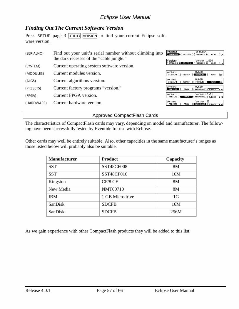
Eclipse User Manual
Release 4.0.1 Page 57 of 66 Eclipse User Manual
Finding Out The Current Software Version Press SETUP page 3 UTILITY VERSION to find your current Eclipse soft-ware.version.
(SERIALNO) Find out your unit’s serial number without climbing into the dark recesses of the “cable jungle.”
(SYSTEM) Current operating system software version. (MODULES) Current modules version. (ALGS) Current algorithms version. (PRESETS) Current factory programs “version.” (FPGA) Current FPGA version. (HARDWARE) Current hardware version.
Approved CompactFlash Cards
The characteristics of CompactFlash cards may vary, depending on model and manufacturer. The follow-ing have been successfully tested by Eventide for use with Eclipse.
Other cards may well be entirely suitable. Also, other capacities in the same manufacturer’s ranges as those listed below will probably also be suitable.
Manufacturer Product Capacity SST SST48CF008 8M SST SST48CF016 16M Kingston CF/8 CE 8M New Media NMT00710 8M IBM 1 GB Microdrive 1G SanDisk SDCFB 16M SanDisk SDCFB 256M
As we gain experience with other CompactFlash products they will be added to this list.
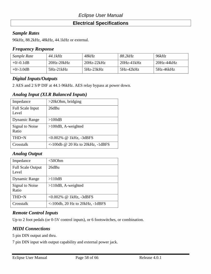
Eclipse User Manual
Eclipse User Manual Page 58 of 66 Release 4.0.1
Electrical Specifications
Sample Rates 96kHz, 88.2kHz, 48kHz, 44.1kHz or external.
Frequency Response Sample Rate 44.1kHz 48kHz 88.2kHz 96kHz +0/-0.1dB 20Hz-20kHz 20Hz-22kHz 20Hz-41kHz 20Hz-44kHz +0/-3.0dB 5Hz-21kHz 5Hz-23kHz 5Hz-42kHz 5Hz-46kHz
Digital Inputs/Outputs 2 AES and 2 S/P DIF at 44.1-96kHz. AES relay bypass at power down.
Analog Input (XLR Balanced Inputs) Impedance >20kOhm, bridging Full Scale Input Level
26dBu
Dynamic Range >100dB Signal to Noise Ratio
>100dB, A-weighted
THD+N <0.002% @ 1kHz, -3dBFS Crosstalk <-100db @ 20 Hz to 20kHz, -1dBFS
Analog Output Impedance <50Ohm Full Scale Output Level
26dBu
Dynamic Range >110dB Signal to Noise Ratio
>110dB, A-weighted
THD+N <0.002% @ 1kHz, -3dBFS Crosstalk <-100db, 20 Hz to 20kHz, -1dBFS
Remote Control Inputs Up to 2 foot pedals (or 0-5V control inputs), or 6 footswitches, or combination.
MIDI Connections 5 pin DIN output and thru. 7 pin DIN input with output capability and external power jack.

Eclipse User Manual
Release 4.0.1 Page 59 of 66 Eclipse User Manual
Power 25 watts 100-125V, 220-240V, AC 50/60Hz
Size Inches: 1.75h x 19w x 12.5d Cm: 4.45h x 48.3w x
31.7d
Weight 12 pounds (5.5 Kg) net, 17 pounds (8Kg) shipping weight All specifications are subject to change or improvement at any time without notice or obligation.
Eclipse User Manual
Eclipse User Manual Page 60 of 66 Release 4.0.1
Warranty Information Eclipse
LIMITED WARRANTY The above-identified Eventide unit covered by this warranty is built to exacting quality standards and should give years of trouble-free service. If you are experi-encing problems which are not cleared up or explained as normal in the manual, your recourse is this warranty. What the warranty does and does not cover Eventide Inc. warrants the above-identified unit to be free from defects in workmanship and material under normal operation and service for a period of one year from the date of purchase, as detailed below. At our discretion within the warranty period, we may elect to repair or replace the defective unit. This means that if the unit fails under normal operation because of such defect, we will repair the defective unit at no charge for parts or labor. We also assume a limited responsi-bility for shipping charges, as detailed below. The warranty does not extend beyond repair or replacement as stated herein and in no event will we be responsible for consequential or incidental damages caused by any defect, and such damages are specifically excluded from this warranty. Our sole obligation is to repair or replace the defective unit as described herein. The warranty DOES NOT COVER any damage to the unit regardless of the cause of that damage. The unit is a complex piece of equipment that does not react well to being dropped, bounced, crushed, soaked or exposed to excessively high temperatures, voltages, electrostatic or electromagnetic fields. If the unit is damaged for these or similar causes, and the unit is deemed to be economically repairable, we will repair it and charge our normal rates. The warranty DOES NOT COVER shipping damage, either to or from Eventide. If you receive a new unit from us in damaged condition, notify us and the carri-er; we will arrange to file an insurance claim and either repair or exchange the unit. If you receive a new unit from a dealer in damaged condition, notify the dealer and the carrier. If we receive the unit from you with apparent shipping damage, we will notify you and the carrier. In this case, you must arrange to collect on any insurance held by you or your carrier. We will await your instructions as to how to proceed with the unit, but we will charge you for all repairs on damaged units. Who is covered under the warranty The warranty applies to the original purchaser of a new unit from Eventide or an Authorized Eventide Dealer. Demo units are also covered by this warranty under slightly different circumstances (see below). Units that are used, or have been used as part of a rental program, are not covered under any circumstances. It is your responsibility to prove or to be able to prove that you have purchased the unit under circumstances which effect the warranty. A copy of your purchase invoice is normally necessary and sufficient for this. If you have any questions about who is an Authorized Eventide Dealer, call us. Units with the serial number plate defaced or removed will not be serviced or covered by this warranty. When the warranty becomes effective The one-year warranty period begins on the day the unit is purchased from an Authorized Eventide Dealer or, if the unit is drop-shipped from Eventide, on the day shipped, plus a reasonable allowance for shipping delays. This applies whether or not you return your warranty registration form. When we receive a unit, this is how we determine whether it is under warranty:
1. If the unit was shipped from our factory within the past calendar year, we assume that it is under warranty unless there is evidence to the contrary, such as its having been sold as used or rented, etc..
2. If the unit was shipped from our factory more than a calendar year ago, we assume it is not under warranty unless: a) There is a warranty registration form on file showing that it has been purchased within the past year under appropriate conditions. b) You send a copy of your purchase invoice indicating warranty status along with the unit.
3. If the unit was used as a demo, the warranty runs from the date that it was received by the dealer. The original purchaser gets the unexpired portion of that warranty.
When you send a unit for repair, you should indicate whether or not you believe it to be under warranty. If you do not say the unit is under warranty, we will charge you for the repair and we will not refund unless the charge was caused by an error on our part. If you believe the unit to be under warranty and you do say it is but we disagree, you will not incur any charges until the dispute is resolved. Reading the above, you can see that it is to your advantage to send in the warranty registration form when you purchase the unit. If we know who you are, we can send you updates and notifications, and advise you of our new products. It will also enable you to receive pre-shipment of certain parts. (c) 1999, 2000 Eventide Inc.
Eclipse User Manual
Release 4.0.1 Page 61 of 66 Eclipse User Manual
Who performs warranty work The only company authorized to perform work under this warranty is Eventide Inc., Little Ferry, New Jersey. While you are free to give personal authorization to anyone else (or to work on it yourself), we will not honor claims for payment for parts or labor from you or from third parties. However, we and our dealers do try to be helpful in various ways: 1. Our dealers will assist, usually without charge during the warranty period, in: a) determining whether there is a problem requiring return to the factory, and b) alleviating user error or interconnection problems that may be preventing the unit from operating to its full capability. 2. We are available for telephone consultation if the dealer is unable to assist. 3. If a part is found to be defective during the warranty period and you wish to replace it yourself, we will normally ship the part immediately at no charge, provided your warranty registration form is on file. We reserve the right to request that the defective part be returned to us. Shipping within the 50 United States You are responsible for getting the unit to our door at no cost to us. We cannot accept collect or COD shipments. We will return the unit to you prepaid, at our expense, using an expeditious shipping method, normally United Parcel Service. In areas not served by UPS we will ship by US Mail. If you are in a hurry and want us to use a premium shipping method (such as air express, next day air, etc.), be sure you tell us and agree to pay shipping charges collect. If you specify a method that does not permit collect or COD charges, remit sufficient funds to prepay shipping. Shipping outside the 50 United States If you purchased the unit from a dealer in your country, consult with the dealer before returning the unit. If you wish to return the unit to us, please note the following: 1. The unit must be prepaid to our door. This means that you are responsible for all shipping charges, including customs brokerage and duties. When a unit is shipped to us it must be cleared through United States Customs by an authorized broker. You must make arrangements for this to be done. Normally, your freight forwarder has a branch in the United States which can handle this transaction. We can arrange to clear incoming shipments for you. If you want our assistance, you must notify us before shipping the unit for repair, giving full details of the shipment, and including a minimum of $250.00 in US funds to cover the administrative and brokerage expenses. Any balance will be applied to the repair charges or refunded. If a balance is due to us, we will request a further prepayment. 2. All shipments will be returned to you collect. If this is impossible because of shipping regulations or money is due us, we will request prepayment from you for the appropriate amount. 3. All funds must be in $US. Payment may be made by check drawn on any bank in the US, or by telegraphic funds transfer to our bank. If you send US currency, be sure that it is sent by a method you can trace, such as registered mail. If you wish to pay by Letter of Credit, be sure that it affords sufficient time for work to be performed and the L/C negotiated, and that it is free from restrictive conditions and documentation requirements. 4. We reserve the right to substitute freight carriers. Although we will attempt to honor your request for a specific carrier, it is frequently necessary to select a substitute because of difficulties in communication or scheduling. This warranty gives you specific legal rights and you may also have other rights which vary from location to location. (c) 1999, 2000 Eventide Inc.

Eclipse User Manual
Release 4.0.1 Page 63 of 66 Eclipse User Manual
Index Algorithms, 8,
33 Loading, 19,
39 Analog input, 9,
14 Guitar, 9, 14
Analog output, 9, 14
Busy LED, 8 MIDI In /
Serial port indicator, 51
Bypass, 8, 24 Effects
blocks, 39 LED blinking,
39 remote, 47
Checksum, 53 Digital
input/output ADAT, 14, 27 Brief
overview, 14, 24
Connectors, 9, 10
External clock, 25
Internal clock, 25
Output format, 26
Selecting input, 24
Status of input, 25
Word Clock, 10, 26
Display, 7 Brightness, 20 Understanding
Layout, 12 Understanding
Page
Numbers, 13
Dumping data, 51
Edited LED, 8 Effect blocks
Loading algorithms, 39
Effects blocks, 6, 33, 34 Bypassing, 39 Routing, 38
Emphasis, 27 EXT LED
blinking, 25 External
Controllers, 45 MIDI capture,
46 Foot Pedal Jacks
As external modulators, 45
Jacks, 11 Loading
Programs with, 47
Setting up, 49 Freezing, 53 Global
parameters, 6 High sampling
rates, unable to load programs, 26
Hot Keys, 7, 33 Assigning, 19,
33 Deleting, 34
Input, stereo or mono?, 22
Keypad, 7, 13 Knob, 8, 13 Levels
Global, 22
Eclipse User Manual- Index
Eclipse User Manual Page 64 of 66 Release 4.0.1
Program-specific, 39
LFO. See Parameters
Memory card, 8, 20, 56
Meter, 8, 21 MIDI
As external modulators, 45
Loading Programs, 29
Ports, 10 Setup, 48 System
exclusive, 48
Use with pedal boards, 10, 11
Modulation block, 6, 8, 40 Individual
modules, 43 Patching
parameters to, 17, 40
Scaling, 41, 47
Naming Things, 32
Optimizing signal quality, 22
Overload, 8, 21 Parameters
Causing a parameter to ignore tempo, 16
Envelope followers, 36
LFO, 36 Master, 34
Modulating. See Modulation block
Retriggering LFO's, 37
Sends, 37 Tap to
determine delay times, 36
Tempo-controlled, 16, 35
Power, 7, 9 Program
key, 7 LED blinking,
50 Programs
Copying. See Crossfading,
29 Interval
during loading, 29
Loading, 7, 15, 16, 28
Loading with MIDI, 29
Removing, 31 Saving, 7, 30 Sorting, 15,
16, 28 User Groups,
31 Rack mounting,
20 Sample rate, 8 serial port
pin-out, 51 Serial port, 10,
51 Setups
Storing and loading, 50
Soft keys, 7
Eclipse User Manual
Release 4.0.1 Page 65 of 66 Eclipse User Manual
Ganged Parameters, 12
Understanding Different Kinds, 12
Software Updating, 56 Version, 57
Storing data externally. See Dumping data
TAP. See Tempo, See Tempo
Tempo, 6, 8, 15, 16, 17 Conceptual
flow chart of, 17
Disabling, 16, 17
Unbalancing analog connectors, 9
User Groups. See Programs
Wet/Dry Global, 22 Program-
specific, 39

Eclipse User Manual- Index
Eclipse User Manual Page 66 of 66 Release 4.0.1
This page is intentionally left blank