Embed Size (px)
Citation preview

Eclipse RatioMaticBurners
Design Guide 1103/15/2013
Version 5RM Series

2
CopyrightCopyright 2010 by Eclipse, Inc. All rights reservedworldwide. This publication is protected by federalregulation and shall not be copied, distributed,transmitted, transcribed or translated into any human orcomputer language, in any form or by any means, to anythird parties, without the express written consent ofEclipse, Inc.
Disclaimer NoticeIn accordance with the manufacturer’s policy of continualproduct improvement, the product presented in thisbrochure is subject to change without notice or obligation.
The material in this manual is believed adequate for theintended use of the product. If the product is used forpurposes other than those specified herein, confirmationof validity and suitability must be obtained. Eclipsewarrants that the product itself does not infringe upon anyUnited States patents. No further warranty is expressed orimplied.
Liability & WarrantyWe have made every effort to make this manual asaccurate and complete as possible. Should you find errorsor omissions, please bring them to our attention so that wemay correct them. In this way we hope to improve ourproduct documentation for the benefit of our customers.Please send your corrections and comments to ourMarketing Communications Manager.
It must be understood that Eclipse’s liability for its product,whether due to breach of warranty, negligence, strictliability, or otherwise is limited to the furnishing ofreplacement parts. Eclipse will not be liable for any otherinjury, loss, damage or expenses, whether direct or
consequential, including but not limited to loss of use,income, or damage to material arising in connection withthe sale, installation, use of, inability to use or the repair orreplacement of Eclipse’s products.
Any operation expressly prohibited in this manual, anyadjustment, or any assembly procedures notrecommended or authorized in these instructions shallvoid the warranty.
Document ConventionsThere are several special symbols in this document. Youmust know their meaning and importance.
The explanation of these symbols follows below. Pleaseread it thoroughly.
How To Get HelpIf you need help, contact your local Eclipse representative.You can also contact Eclipse at:
1665 Elmwood Rd.Rockford, Illinois 61103 U.S.A.Phone: 815-877-3031Fax: 815-877-3336http://www.eclipsenet.com
Please have the information on the product label availablewhen contacting the factory so we may better serve you.
Product NameItem #S/NDD MMM YYYY
www.eclipsenet.com
This is the safety alert symbol. It is used to alert you to potential personalinjurt hazards. Obey all safety messages that follow this symbol to avoidpossible injury or death.
Indicates a hazardous situation which, if not avoided, will result in deathor serious injury.
Indicates a hazardous situation which, if not avoided, could result indeath or serious injury.
Indicates a hazardous situation which, if not avoided, could result inminor or moderate injury.
Is used to address practices not related to personal injury.
Indicates an important part of text. Read thoroughly.NOTENOTICE
CAUTION
WARNING

3Eclipse RatioMatic Burner, RM Series, V5, Design Guide 110, 3/15/2013
Table of ContentsIntroduction .............................................................................................. 4
Product Description....................................................................... 4
Audience ....................................................................................... 4
RatioMatic Documents .................................................................. 5
Purpose......................................................................................... 5
Safety ........................................................................................................ 5
Introduction ................................................................................... 5
Safety ............................................................................................ 5
Capabilities.................................................................................... 5
Operator Training .......................................................................... 5
Replacement Parts........................................................................ 5
System Design ......................................................................................... 7
Design ........................................................................................... 7
Step 1: Burner Option Selection.................................................... 7
Step 2: Blower Option Selection ................................................... 9
Step 3: Control Methodology......................................................... 10
Step 4: Ignition System ................................................................. 11
Step 5: Flame Monitoring Control System .................................... 11
Step 6: Main Gas Shut-Off Valve Train......................................... 12
Appendix................................................................................................... i
Conversion Factors ....................................................................... i
Key to System Schematics ........................................................... ii

4 Eclipse RatioMatic Burner, RM Series, V5, Design Guide 110, 3/15/2013
IntroductionProduct Description
The RatioMatic is a nozzle-mix type burner designed fordirect and indirect air heating and oven applications up to1900°F (1040°C).
The burner package includes a combustion air blower andan air:gas ratio regulator to fire over a wide gas turndownrange at a controlled ratio.
The burner is designed for:
• efficient ratio controlled combustion• reliable burner operation• simple burner adjustment• direct spark ignition• multiple fuel capability
A wide variety of options and configurations are availabledue to the modular design of the burner.
AudienceThis manual has been written for people who are alreadyfamiliar with all aspects of a nozzle-mix burner and its add-on components, also referred to as “the burner system”.
These aspects are:• Design / Selection• Use• Maintenance
The audience is expected to have previous experiencewith this type of equipment.
Figure 1.1. RatioMatic Burner (RM0050 - RM0700)
Figure 1.2. RatioMatic Burner (RM1000 - RM3000)
1
5Eclipse RatioMatic Burner, RM Series, V5, Design Guide 110, 3/15/2013
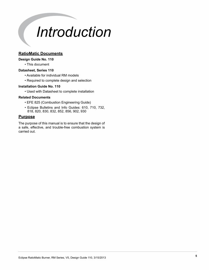
IntroductionRatioMatic DocumentsDesign Guide No. 110
• This document
Datasheet, Series 110 • Available for individual RM models• Required to complete design and selection
Installation Guide No. 110• Used with Datasheet to complete installation
Related Documents• EFE 825 (Combustion Engineering Guide)• Eclipse Bulletins and Info Guides: 610, 710, 732,
818, 820, 830, 832, 852, 856, 902, 930PurposeThe purpose of this manual is to ensure that the design ofa safe, effective, and trouble-free combustion system iscarried out.

6
SafetyImportant notices which help provide safe burneroperation will be found in this section. To avoid personalinjury and damage to the property or facility, the followingwarnings must be observed. All involved personnel shouldread this entire manual carefully before attempting to startor operate this system. If any part of the information in thismanual is not understood, contact Eclipse beforecontinuing.
Safety Warnings
■ The burners, described herein, are designed to mixfuel with air and burn the resulting mixture. All fuelburning devices are capable of producing fires andexplosions if improperly applied, installed,adjusted, controlled or maintained.
■ Do not bypass any safety feature; fire or explosioncould result.
■ Never try to light a burner if it shows signs ofdamage or malfunction.
■ The burner and duct sections are likely to haveHOT surfaces. Always wear the appropriateprotective equipment when approaching theburner.
■ Eclipse products are designed to minimize the useof materials that contain crystalline silica.Examples of these chemicals are: respirablecrystalline silica from bricks, cement or othermasonry products and respirable refractoryceramic fibers from insulating blankets, boards, orgaskets. Despite these efforts, dust created bysanding, sawing, grinding, cutting and otherconstruction activities could release crystallinesilica. Crystalline silica is known to cause cancer,and health risks from the exposure to thesechemicals vary depending on the frequency andlength of exposure to these chemicals. To reducethe risk, limit exposure to these chemicals, work ina well-ventilated area and wear approved personalprotective safety equipment for these chemicals.
■ This manual provides information regarding theuse of these burners for their specific designpurpose. Do not deviate from any instructions orapplication limits described herein without writtenapproval from Eclipse.
CapabilitiesOnly qualified personnel, with sufficient mechanicalaptitude and experience with combustion equipment,should adjust, maintain or troubleshoot any mechanical orelectrical part of this system.
Operator TrainingThe best safety precaution is an alert and trainedoperator. Train new operators thoroughly and have themdemonstrate an adequate understanding of theequipment and its operation. A regular retraining scheduleshould be administered to ensure operators maintain ahigh degree of proficiency.
Replacement PartsOrder replacement parts from Eclipse only. All Eclipseapproved valves or switches should carry UL, FM, CSA,CGA and/or CE approval where applicable.
DANGER
WARNING
NOTICE
2

Eclipse RatioMatic Burner, RM Series, V5, Design Guide 110, 3/15/2013 7
DesignThe design process is divided into the following steps:
1. Burner Option Selection Including:• Burner Model / Size • Firing Position• Burner Configuration• Fuel Type• Fuel Supply• Combustor Type and Material• Combustor Length• Nozzle Type• Air Supply• Control Motor• Limit Switch• Loading Line Type• Air Pressure Switch• Piping Connection• Flame Supervision
2. Blower Option Selection Including:• Power Supply Frequency• Pressure and Flow• Blower Motor Type• Blower Inlet• Motor Orientation
3. Control Methodology Including:• Burner Control
4. Ignition System Including:• Ignition Transformer• Trial for Ignition• Ignition Gas Piping
5. Flame Monitoring Control System Including:• Flame Sensor• Flame Monitoring Control
6. Main Gas Shut-Off Valve Train Including:• Component Selection• Valve Train Size
Step 1: Burner Option Selection
Step 1 describes how to select burner options to suit anapplication. Use the RatioMatic Price Lists andDatasheets, series 110 when following this selectionprocess.
■ Consult EFE-825 Eclipse Engineering Guide orcontact Eclipse if you have special conditions orquestions.
Burner Model / Size Selection
Consider the following when selecting the burner size:
• Heat Input: Calculate the required heat input to achieve the required heat balance.
• Power Supply Frequency: Burner capacity will vary with power supply frequency (50 Hz or 60 Hz power).
• Combustion Chamber Pressure: Consider the effects that large or varying chamber pressures have on burner performance.
• Altitude: The maximum burner capacity is reduced by approximately 3% each 1000 feet (300 meters) above sea level.
• Combustion Air Supply: Combustion air should be fresh (20.9% O2) and clean (without particles or corrosives).
• Combustion Air Temperature: Changes in air supply temperature can affect the burner capacity. Contact Eclipse if the combustion air temperature exceeds 150°F (65°C).
• Fuel Type: Variation in calorific value, specific gravity and WOBBE index will affect burner performance. If any of these parameters change more than ±5% from Figure 3.1 contact Eclipse to check the suitability of the fuel. Performance data, dimensions and specifications are given for each RatioMatic in Datasheets Series No.110.
CAUTION
System Design 3
8 Eclipse RatioMatic Burner, RM Series, V5, Design Guide 110, 3/15/2013
Firing Position• Vertical Down Firing (Available for RM0050 through
RM0700)• Vertical Up Firing (Available for RM0050 through
RM0700)• Horizontal Firing
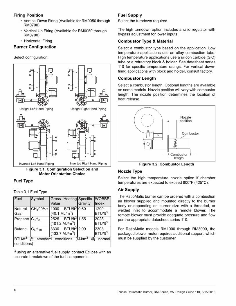
Burner Configuration
Select configuration.
Figure 3.1. Configuration Selection and Motor Orientation Choice
Fuel Type
Table 3.1 Fuel Type
If using an alternative fuel supply, contact Eclipse with anaccurate breakdown of the fuel components.
Fuel SupplySelect the turndown required.
The high turndown option includes a ratio regulator withbypass adjustment for lower inputs.
Combustor Type & MaterialSelect a combustor type based on the application. Lowtemperature applications use an alloy combustion tube.High temperature applications use a silicon carbide (SiC)tube or a refractory block & holder. See datasheet series110 for specific temperature ratings. For vertical down-firing applications with block and holder, consult factory.
Combustor LengthSelect a combustor length. Optional lengths are availableon some models. Nozzle position will vary with combustorlength. The nozzle position determines the location ofheat release.
Figure 3.2. Combustor Length
Nozzle TypeSelect the high temperature nozzle option if chambertemperatures are expected to exceed 800°F (425°C).
Air SupplyThe RatioMatic burner can be ordered with a combustionair blower supplied and mounted directly to the burnerbody or depending on burner size with a threaded, orwelded inlet to accommodate a remote blower. Theremote blower must provide adequate pressure and flowper the appropriate datasheet series 110.
For RatioMatic models RM1000 through RM3000, thepackaged blower motor requires additional support, whichmust be supplied by the customer.
Fuel Symbol Gross HeatingValue
SpecificGravity
WOBBEIndex
NaturalGas
CH490%+ 1000 BTU/ft3(40.1 MJ/m3)
0.60 1290BTU/ft3
Propane C3H8 2525 BTU/ft3(101.2 MJ/m3)
1.55 2028BTU/ft3
Butane C4H10 3330 BTU/ft3(133.7 MJ/m3)
2.09 2303BTU/ft3
BTU/ft3 @ standard conditions (MJ/m3 @ normalconditions)
Upright Left Hand Piping Upright Right Hand Piping
Inverted Left Hand Piping Inverted Right Hand Piping
Noz
zle
Combustorlength
Combustor
Nozzleposition

9Eclipse RatioMatic Burner, RM Series, V5, Design Guide 110, 3/15/2013
Control Motor
Select a control motor. Eclipse Trilogy T500 actuators arestandard on all Eclipse packaged burners, other controlmotor options are available which Eclipse will mount to theburner. RatioMatic burners can be ordered with controlmotor bracket and mounting hardware only. Customersupplied control motors must conform to thesespecifications:
• rotation not to exceed 2 rpm• minimum torque of 25 in-lb (2,8 Nm)• 90° stroke• continuous modulating or high/low modulating
control• reversible direction of rotation• certain applications may require control motors with
a limit switch or switches if:- the burner capacity is to be limited to fit an
application- the chamber is to be fired with positive or
negative pressure- the chamber pressure is outside the range
-1" w.c. to +1" w.c. (-2,5 to 2,5 mbar)- there is a need to indicate a high and/or low
fire air butterfly valve positionLimit Switch
Limit switches monitor the position of the integral airbutterfly valve. Select high, low, high and low, or no limitswitch option. Proper selection is based on preference,control system, and local code.
Loading Line TypeAll RatioMatic burners have the option of plastic, flexiblebraided stainless steel or rigid stainless tube loading line.Selection depends on application and environment.
Piping ConnectionSelect the gas pipe connection including the pipe threadtype and the turndown required.
The piping, burner gas inlet, and ratio regulator arethreaded using the customer selected pipe thread option.
The high turndown option includes a ratio regulator withan adjustment for lower inputs.
Flame SupervisionDetermine if a flame rod or an ultraviolet (UV) scanner willbe required. Flame rods are available on models RM0050through RM0700, burners with alloy or SiC tubes. All otheroptions and models require UV scanners. If a UV scanneris required, it must be ordered separately.
NOTE: Some flame monitoring devices do not work withalternative fuels. Consult Eclipse for assistance whenselecting flame monitoring equipment for alternative fuels.
See Step 5 for additional information on flame supervisionselection.
■ A UV scanner could possibly detect anotherburner’s flame if it is in the line of sight, and falselyindicate flame presence.
Step 2: Blower Option SelectionStandard blower options are listed in datasheet series110, additional blower options are available throughEclipse. Price and leadtime may vary.
Power Supply FrequencySelect the 50Hz or 60Hz option. The 50Hz blower motorshave IEC frames and are CE marked. The 60Hz motorshave NEMA frames.
Pressure & FlowEclipse offers SMJ blowers for remote blowerapplications. The RatioMatic burner can be ordered with acombustion air blower supplied and mounted directly tothe burner body or with a threaded, flanged, or weldedinlet to accommodate a remote blower. Remote blowermust provide adequate pressure and flow per theappropriate datasheet series 110.
Blower Motor TypeMotor types include various options: voltages, single orthree phase, TEFC or automotive duty enclosures.
Blower InletWhen selecting an inlet, consider the following:
• amount and size of particles in the air• sound level requirements• space limitations• cleanliness requirements of the process
Motor OrientationRight-hand blower motor orientation is standard. If left-hand blower motor orientation is required, contact factory.
WARNING

10 Eclipse RatioMatic Burner, RM Series, V5, Design Guide 110, 3/15/2013
Figure 3.3. Burner Configuration &Motor Orientation Choice
Step 3: Control Methodology
Figure 3.4. Air : Gas Flow
All standard RatioMatic burners are designed for:
• air:gas ratio controlled combustion• 10 - 15% excess air at high fire• higher excess air at low fire
Burner Control
RatioMatic burners come with a ratio regulator thatmaintains the air:gas ratio, see figure 3.4.
Figure 3.5. Basic Burner Component (RM0050 - RM0700)
Figure 3.6. Basic Burner Component (RM1000 - RM3000)
• A control signal is sent from a process temperature controller (sold separately) to the control motor. (Refer to Bulletin 818C or contact Eclipse for further information on temperature controllers.)
Figure 3.7. Basic Control Loop
• The control motor modulates the air butterfly valve (BV) which controls the combustion air flow.
• Air pressure in the burner body sends an impulse down the loading line to the ratio regulator.
• The ratio regulator controls the gas flow in proportion to the air flow.
■ Do not use other control methods, such as fixed-air control, or alter the ratio regulator or burnerpiping without prior approval from Eclipse.
Upright Left Hand Piping Upright Right Hand Piping
Gas
Air
Stoich
iometr
ic
Ratio control operatio
n
Excess air
PackagedBlower
ControlMotor
RatioRegulator
PackagedBlower
ControlMotorHigh Fire
Valve
RatioRegulator
Control Signal
Gas FlowProcess
Set Point ProcessController
Control Motor
AirBV
RatioRegulator
Tem
pera
ture
Pre
ssur
eIm
puls
e
WARNING
11Eclipse RatioMatic Burner, RM Series, V5, Design Guide 110, 3/15/2013
Step 4: Ignition SystemIgnition Transformer
For the ignition system, use a transformer with:
• secondary voltage 6,000 to 8,000 VAC• minimum secondary current 0.02 amps• full wave output
DO NOT USE the following:
• twin outlet• distributor type• electronic type
Trial for Ignition
It is recommended that low fire start be used. However,under certain circumstances RatioMatic burners arecapable of direct spark ignition at higher gas inputs.
Most local safety codes and insurance requirements limitthe maximum trial for ignition time (the time it takes for aburner to ignite). These requirements vary from onelocation to another; check your local codes and comply tothe strictest codes applicable.
The time it takes for a burner to ignite depends on thefollowing:
• the distance between the gas shut-off valve and the burner
• the air:gas ratio• the gas flow conditions at start-up
The possibility exists where the low fire settings areinsufficient to ignite the burner within the maximum trial forignition time. The following options must be consideredunder these conditions:
• start at higher gas input levels• resize and/or relocate the gas controls• use bypass start gas
Ignition Gas Piping
RatioMatic burners are capable of ignition with either lowfire or bypass start gas.
Figure 3.8. Low Fire Start
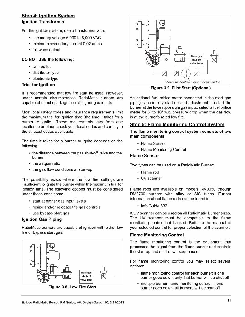
Figure 3.9. Pilot Start (Optional)
An optional fuel orifice meter connected in the start gaspiping can simplify start-up and adjustment. To start theburner at the lowest possible gas input, select a fuel orificemeter for 5" to 10" w.c. pressure drop when the gas flowis at the burner’s rated low fire.
Step 5: Flame Monitoring Control SystemThe flame monitoring control system consists of twomain components:
• Flame Sensor• Flame Monitoring Control
Flame Sensor
Two types can be used on a RatioMatic Burner:
• Flame rod• UV scanner
Flame rods are available on models RM0050 throughRM0700 burners with alloy or SiC tubes. Furtherinformation about flame rods can be found in:
• Info Guide 832
A UV scanner can be used on all RatioMatic Burner sizes.The UV scanner must be compatible to the flamemonitoring control that is used. Refer to the manual ofyour selected control for proper selection of the scanner.
Flame Monitoring ControlThe flame monitoring control is the equipment thatprocesses the signal from the flame sensor and controlsthe start-up and shut-down sequences.
For flame monitoring control you may select severaloptions:
• flame monitoring control for each burner: if one burner goes down, only that burner will be shut off
• multiple burner flame monitoring control: if one burner goes down, all burners will be shut off
Main gasshut-off
valve train
Main gasshut-off
valve train
�ptional fuel orifice meter recommended

12 Eclipse RatioMatic Burner, RM Series, V5, Design Guide 110, 3/15/2013
Eclipse recommends the following flame monitoringcontrols:
• Trilogy series T400; see Instruction Manual 830• Veri-Flame series 5600: see Instruction Manual 818• Bi-Flame series 6500: see Instruction Manual 826• Multi-Flame series 6000; see Instruction Manual
820
■ If other controls are considered, contact Eclipse todetermine how burner performance may beaffected. Flame monitoring controls that havelower sensitivity flame detecting circuits may limitburner turndown and change the requirements forignition. Flame monitoring controls that stop thespark as soon as a signal is detected may preventestablishment of flame, particularly when using UVscanners. The flame monitoring control mustmaintain the spark for a fixed time interval that islong enough for ignition.
DO NOT USE the following:
• Flame monitoring relays which interrupt the trial for ignition when the flame is detected.
• Flame sensors which supply a weak signal.• Flame monitoring relays with low sensitivity.
Step 6: Main Gas Shut-Off Valve TrainComponent SelectionEclipse can help in the design of a main gas shut-off valvetrain that satisfies the customer and complies with all localsafety standards and codes set by the authorities withinthat jurisdiction. Contact Eclipse for further information.
NOTE: Eclipse supports NFPA regulations (two gas shut-off valves as a minimum standard for main gas shut-offsystems).
Valve Train Size
Fuel pressure supplied to the ratio regulator inlet must bewithin the range specified in the RatioMatic datasheet.The valve train should be sized sufficiently to provide thespecified pressure.
■ Do not operate RatioMatic burners with gas inletpressure less than the minimum listed on theRatioMatic datasheet. Lower gas inlet pressuremay cause the ratio regulator to remain fully openat lower inputs as the burner transitions from lowto high fire. This can result in the possibleaccumulation of unburned fuel in the burnerwhich, in extreme situations, could cause a fire oran explosion.
NOTICE
WARNING

i
Conversion Factors
Metric to English
Metric to Metric
English to Metric
From To Multiply Byactual cubic meter/h (am³/h) actual cubic foot/h (acfh) 35.31normal cubic meter/h (Nm³/h) standard cubic foot /h (scfh) 38.04
degrees Celsius (°C) degrees Fahrenheit (°F) (°C x 9/5) + 32kilogram (kg) pound (lb) 2.205kilowatt (kW) Btu/h 3415
meter (m) foot (ft) 3.281millibar (mbar) inches water column ("w.c.) 0.402millibar (mbar) pounds/sq in (psi) 14.5 x 10⁻³
millimeter (mm) inch (in) 3.94 x 10⁻²
MJ/Nm³ Btu/ft³ (standard) 26.86
From To Multiply BykiloPascals (kPa) millibar (mbar) 10
meter (m) millimeter (mm) 1000millibar (mbar) kiloPascals (kPa) 0.1millimeter (mm) meter (m) 0.001
From To Multiply By
actual cubic foot/h (acfh) actual cubic meter/h (am³/h) 2.832 x 10⁻²
standard cubic foot /h (scfh) normal cubic meter/h (Nm³/h) 2.629 x 10⁻²
degrees Fahrenheit (°F) degrees Celsius (°C) (°F - 32) x 5/9pound (lb) kilogram (kg) 0.454
Btu/h kilowatt (kW) 0.293 x 10⁻³
foot (ft) meter (m) 0.3048inches water column ("w.c.) millibar (mbar) 2.489
pounds/sq in (psi) millibar (mbar) 68.95inch (in) millimeter (mm) 25.4
Btu/ft³ (standard) MJ/Nm³ 37.2 x 10⁻³
Appendix

ii
Symbol Appearance Name Remarks Bulletin/Info Guide
Gas Cock Gas cocks are used to manually shut off the gas supply. 710
Ratio Regulator
A ratio regulator is used to control the air/gas ratio. The ratio regulator is a sealed unit that adjusts the gas pressure in ratio with the air presssure. To do this, it measures the air pressure with a pressure sensing line, the impulse line. This impulse line is connected between the top of the ratio regulator and the burner body.
742
Main Gas Shut-Off Valve Train
Eclipse strongly endorses NFPA as a minimum. 790/791
Pilot Gas Valve Train Eclipse strongly endorses NFPA as a minimum. 790/791
Automatic Shut-OffValve
Shut-off valves are used to automatically shut off the gas supply on a gas system or a burner.
760
Orifice Meter Orifice meters are used to measure flow. 930
Combustion Air Blower The combustion air blower provides the combustion air to the burner(s). 610
Main GasShut-Off
ValveTrain
Pilot GasShut-Off
Valve Train
System Schematics

iii
Hermetic Booster Booster is used to increase gas pressure. 620
Automatic Butterfly Valve Automatic butterfly valves are typically used to set the output of the system. 720
Manual Butterfly Valve Manual butterfly valve are used to balance the air or gas flow at each burner. 720
Adjustable Limiting Orifice
Adjustable limiting orifices are used for fine adjustment of gas flow. 728/730
Pressure Switch
A switch activated by rise or fall in pressure. A manual reset version requires pushing a button to transfer the contacts when the pressure set point is satisfied.
840
Pressure Gauge A device to indicate pressure. 940
Check ValveA check valve permits flow only in one direction and is used to prevent back flow of gas.
780
Strainer A strainer traps sediment to prevent blockage of sensitive components downstream.
Flexible Connector Flexible connectors isolate components from vibration, mechanical, and thermal stresses.
Heat Exchanger Heat exchangers transfer heat from one medium to another. 500
Pressure Taps Pressure taps measure static pressure.
Symbol Appearance Name Remarks Bulletin/Info Guide
Offered By:Power Equipment Company 2011 Williamsburg Road Richmond, Virginia 23231 Tel: 804-236-3800 Fax: 804-236-3882 www.peconet.com