Embed Size (px)
Citation preview

Eclipse®
Enhanced Model 705Guided Wave RadarLevel TransmitterFor Heavy-Duty Applications
A P P L I C A T I O N S
MEDIA: Liquids or slurries; hydrocarbons to water-basedmedia (dielectric 1.4 - 100).
VESSELS: Most process or storage vessels up to ratedprobe temperature and pressure.
CONDITIONS: All level measurement and control appli-cations including process conditions exhibiting visiblevapors, foam, surface agitation, bubbling or boiling, highfill/empty rates, low level and varying dielectric media orspecific gravity.
Download your free copy of the ECLIPSE 705 performancereports by WIB/Evaluation International (SIREP)/EXERAfrom magnetrol.com.
Eclipse® withEnlarged CoaxialGWR probe
Eclipse® withCaged GWR probe
Overfill-Safe Probes for Clean & Dirty LiquidsD E S C R I P T I O N
The Enhanced Eclipse® Model 705 Transmitter is a loop-
powered, 24 VDC liquid-level transmitter based on the
revolutionary Guided Wave Radar (GWR) technology.
Encompassing a number of significant engineering
accomplishments, this leading edge level transmitter is
designed to provide measurement performance well
beyond that of many traditional technologies, as well as
“through-air” radar.
The innovative enclosure is a first in the industry, orient-ing dual compartments (wiring and electronics) in thesame plane, and angled to maximize ease of wiring, con-figuration, and data display.
One universal transmitter can be used with all probetypes and offers enhanced reliability for use in SIL 2/SIL 3hardware systems.
ECLIPSE supports the FDT/DTM standard and, with thePACTware™ frame program, allows for additional config-uration and trending flexibility.
F E A T U R E S
• “TRUE LEVEL” measurement—not affected by mediacharacteristics (e.g., dielectrics, pressure, density, pH,viscosity, etc.)
• Two-wire, 24 VDC loop-powered transmitter forlevel, interface, or volume.
• 20-point custom strapping table for volumetricoutput.
• 360° rotatable housing can be dismantled withoutdepressurizing the vessel.
• Two-line, 8-character LCD and 3-button keypad.
• Probe designs: up to +800° F / 6250 psi (+430° C /430 bar).
• Saturated steam applications up to 2250 psi @+650° F (155 bar @ +345° C).
• Cryogenic applications down to -320° F (-196° C).
• Integral or remote electronics (up to 12 feet (3.6 m)).
• Certified for use in SIL 2/SIL 3 Loops (full FMEDAreport available).
Measure toTop of Probe
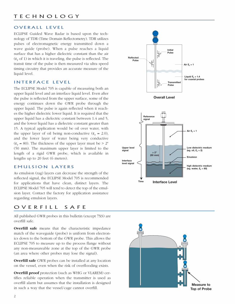
OV E RA L L L E V E L
ECLIPSE Guided Wave Radar is based upon the tech-nology of TDR (Time Domain Reflectometry). TDR utilizespulses of electromagnetic energy transmitted down awave guide (probe). When a pulse reaches a liquidsurface that has a higher dielectric constant than the air(εr of 1) in which it is traveling, the pulse is reflected. Thetransit time of the pulse is then measured via ultra speedtiming circuitry that provides an accurate measure of theliquid level.
I N T E R F AC E L E V E L
The ECLIPSE Model 705 is capable of measuring both anupper liquid level and an interface liquid level. Even afterthe pulse is reflected from the upper surface, some of theenergy continues down the GWR probe through theupper liquid. The pulse is again reflected when it reach-es the higher dielectric lower liquid. It is required that theupper liquid has a dielectric constant between 1.4 and 5,and the lower liquid has a dielectric constant greater than15. A typical application would be oil over water, withthe upper layer of oil being non-conductive (εr ≈ 2.0),and the lower layer of water being very conductive(εr ≈ 80). The thickness of the upper layer must be > 2"(50 mm). The maximum upper layer is limited to thelength of a rigid GWR probe, which is available inlengths up to 20 feet (6 meters).
EMU L S I ON LA Y E R S
As emulsion (rag) layers can decrease the strength of thereflected signal, the ECLIPSE Model 705 is recommendedfor applications that have clean, distinct layers. TheECLIPSE Model 705 will tend to detect the top of the emul-sion layer. Contact the factory for application assistanceregarding emulsion layers.
All published GWR probes in this bulletin (except 7XS) areoverfill safe.
Overfill safe means that the characteristic impedancematch of the waveguide (probe) is uniform from electron-ics down to the bottom of the GWR probe. This allows theECLIPSE 705 to measure up to the process flange withoutany non-measureable zone at the top of the GWR probe(an area where other probes may lose the signal).
Overfill safe GWR probes can be installed at any locationon the vessel, even when the risk of overflooding exists.
Overfill proof protection (such as WHG or VLAREM) cer-tifies reliable operation when the transmitter is used asoverfill alarm but assumes that the installation is designedin such a way that the vessel/cage cannot overfill.
O V E R F I L L S A F E
2
Overall Level
ReflectedPulse
InitialPulse
Air εεr = 1
Liquid εεr > 1.4for coaxial probes
TransmittedPulse
T E C H N O L O G Y
Air εεr = 1
Reference signal
Time
Upper levelsignal
> 2"(50 mm)
Interface level signal
Interface Level
Low dielectric medium(eg. oil, εεr = 2)
Emulsion
high dielectric medium(eg. water, εεr = 80)

COAX I A L P RO B E S
The Coaxial probe is the most efficient of all probe configurations and should be
the first consideration in all applications. Analogous to the efficiency of modern,
coaxial cable, coaxial probes allow almost unimpeded movement of the high
frequency pulses throughout its length.
The electromagnetic field that develops between the inner rod and outer tube is
completely contained. See Figure 1. The efficiency and sensitivity of a coaxial
configuration yields robust signal strength even in extremely low dielectric
(εr ≥1.4) applications. The sensitivity of this “closed” design, however, also makesit more susceptible to measurement error in applications of coating and buildup.
3 S T Y L E S O F T H E COAX I A L GWR P RO B E
Standard coaxial GWR probes for clean liquids
The standard (0.875" diameter) coaxial GWR probes are
recommended for use in clean applications or special
applications such as saturated steam. Spacers are located
at 24-inch intervals centering the inner rod in the outer
tube, obtaining a
perfect characteristic
impedance along the
entire length of the
probe. This probe
can be used in appli-
cations with viscosi-
ties up to 500 cP.
Enlarged coaxial GWR probes for clean liquids.
The enlarged (1.75" diameter) coaxial GWR probes can be
generally used for most applications. They can be installed
directly in the tank as well as into bypass cages, stillwells or
bridles. The robust construction reduces the number of spac-
ers required, allowing the probe to be used in applications
where higher risk of buildup exists. The use of a single
bottom spacer is recommended up to probe lengths of 10
feet. The overall performance of an enlarged coaxial GWR
probe is identical to a standard coaxial GWR probe, but
can be used in applications with viscosities up to 2,000 cP.
Caged GWR probe for dirty liquids
The Caged GWR probe is a single rod probe
which uses an existing or new cage, bridle
or stillwell to re-create the same signal
propagation of a coaxial GWR probe. Caged
GWR probes are designed for 2" (DN50),
3" (DN80) or 4" (DN100) diameter chambers
and utilize an impedance matching section
that results in the same characteristic imped-
ance of a coaxial style GWR probe. Caged
GWR probes are overfill safe, offer the same
performance of coaxial GWR probes, and
can be used in applications with viscosities
up to 10,000 cP.
P R O B E O V E R V I E W
Figure 1
Coaxial Probe
Choosing the proper Guided Wave Radar (GWR) probe is the most important decision in the application process. The
probe configuration establishes fundamental performance characteristics. Coaxial, twin element (rod or cable) and single
element (rod or cable) are the three basic configurations used today; each with specific strengths and weaknesses.
This bulletin focuses on coaxial probes. Refer to bulletin 57-101 for information on other types of GWR probes.
F L U S H I NG CONNEC T ION
The maintenance of coaxial GWR probes in applications
suffering from buildup, crystallization or condensation can
be significantly improved by using a flushing connection.
This flushing connection is a metal extension with a vent,
welded above the process connection. With the vent it is
possible to purge the inside of the coaxial GWR probe
during routine maintenance. The best approach to defeat
the effects of condensation or crystalliza-
tion is to install adequate insulation or
heat tracing (steam or electrical). A flush-
ing connection is no substitute for proper
maintenance but will help to
reduce/optimize the frequency of the
maintenance routines.FlushingConnection
CagedGWR probe
Small CoaxialGWR probe
Enlarged CoaxialGWR probe
3

T R A N S M I T T E R S P E C I F I C A T I O N S
F U N C T I O N A L / P H Y S I C A L
Not applicable for FOUNDATION fieldbus™ and PROFIBUS PA™ units.
Power (at terminals) General Purpose / Intrinsically Safe 11 to 28.6 VDCExplosion Proof (with Intrinsically Safe probe) 11 to 36 VDCFOUNDATION fieldbus™ and PROFIBUS PA™ (FISCO) 9 to 17.5 VDCFOUNDATION fieldbus™ and PROFIBUS PA™ (FNICO Exd) 9 to 32 VDC
Signal Output 4-20 mA with HART® 3.8 mA to 20,5 mA useable (meets NAMUR NE 43)FOUNDATION fieldbus™ H1 (ITK Ver. 5.01) or PROFIBUS PA™ H1PROFIBUS PA™
Span 6 to 240" (150 to 6100 mm) except 7xS: max 180" (4500 mm)Resolution Analog: 0.01 mA
Display: 0.1 cm (inch)Loop Resistance 630 Ω @ 20.5 mA - 24 VDCDamping Adjustable 0-10 sDiagnostic Alarm Adjustable 3.6 mA, 22 mA, HOLDUser Interface HART® communicator, AMS® or PACTware®, FOUNDATION fieldbus™, PROFIBUS PA™,
and/or 3-button keypad Display 2-line x 8-character LCDMenu Language English/Spanish/French/German (FOUNDATION fieldbus™ and PROFIBUS PA: English)Housing Material IP 66/Aluminium A356T6 (< 0.20 % copper) or 316 stainless steelSIL (Safety IntegrityLevel)
Standard electronics
Functional safety to SIL 1 as 1oo1 / SIL 2 as 1oo2 in accordance to 61508 – SFF of 85,4 %– full FMEDA reports and declaration sheets available at request
Enhanced electronics
Functional safety to SIL 2 as 1oo1 in accordance to 61508 – SFF of 91 %– full FMEDA reports and declaration sheets available at request. Certified for use in SIL 3 Loops.
Electrical Data Ui = 28.4 V, li = 94 mA, Pi = 0.67 WUi = 0.56 V, li = 380 mA, Pi = 5.32 W (FOUNDATION fieldbus™ / PROFIBUS PA™)
Equivalent Data Ci = 2.2 nF, Li = 3 µHCi = 0.24 nF, Li = 3 µH (FOUNDATION fieldbus™ / PROFIBUS PA™)
Shock/Vibration Class ANSI/ISA-571.03 SA1 (Shock), ANSI/ISA-571.03 VC2 (Vibration)Net and GrossWeight
Cast aluminium 6 lbs. (2.7 kg) net; 7 lbs. (3.2 kg) gross – transmitter onlyStainless steel 12.5 lbs. (5.7 kg) net; 13.5 lbs. (6.2 kg) gross – transmitter only
Overall Dimensions H 8.43" (214 mm) x W 4.38" (111 mm) x D 7.40" (188 mm)FOUNDATION fieldbus™
specificationsITK Version 5.01H1 Device Class Link Master (LAS) – selectable ON/OFFH1 Profile Class 31PS, 32LFunction Blocks 1 x RB (s), 4 x AI (s), 1 x TB (c), and (1) PIDQuiescent current draw 15 mAExecution time 15 ms (40 msec PID Block)CFF files Downloads available from Host system supplier or www.fieldbus.org
PROFIBUS PA specifications
Device revision 0x01Digital communicationprotocol
Version 3.0 MBP (31.25 kbits/sec)
Function Blocks 1 × PB, 4 × Al blocks, 1 × TBQuiescent current draw 15 mAExecution time 15 msGSD files Downloads available from www.profibus.com or Magnetrol.com
4

Specifications may degrade with fixed threshold configuration.
Top 24 inches of Model 7xB probe: 1.2 inches (30 mm).
Reference Conditions with a 72" coaxial typeGWR probe
Reflection from liquid, with dielectric in center of selected range, at +70° F (+20° C) with CFDthreshold
Linearity Coaxial/twin lead probes < 0.1 % of probe length or 0.1" (2.5 mm), whichever is greaterSingle lead probes < 0.3 % of probe length or 0.3" (8 mm), whichever is greater
Accuracy Coaxial/twin lead probes < 0.1 % of probe length or 0.1" (2.5 mm), whichever is greaterSingle lead probes ± 0.5 % of probe length or 0.5" (13 mm), whichever is greater7xT/7xL interface ± 1" (25 mm)
Resolution ± 0.1" (2.5 mm)Repeatability < 0.1" (2.5 mm)Hysteresis < 0.1" (2.5 mm)Response Time < 1 secondWarm-up Time < 5 secondsAmbient Temp. -40° to +175° F (-40° to +80° C) – blind transmitter
-5° to +160° F (-20° to +70° C) – with digital display-40° to +160° F (-40° to +70° C) – for EEx ia and EEx d[ia] with blind transmitter-5° to +160° F (-20° to +70° C) – for EEx ia and EEx d[ia] with digital display
Process Dielectric Effect < 0.3" (7.5 mm) within selected rangeOperating Temp. Effect Approx. +0.02 % of probe length/°C for probes ≥ 8' (2.5 m)Humidity 0-99 %, non-condensingElectromagnetic Compatibility Meets CE requirements (EN-61326: 1997 + A1 + A2) and NAMUR NE 21
(Single and Twin Rod probe must be used in metallic vessel or stillwell)Surge Protection Meets CE EN61326 (1000 V)
5
T R A N S M I T T E R S P E C I F I C A T I O N S
P E R F O R M A N C E
1200
1000
800
600
400
200
0
0 10 20 30 40VDC
GENERAL PURPOSE (GP)INTRINSICALLY SAFE (IS)EXPLOSION PROOF (XP)
20.5 mA
24 VDC
630
11
Ω

Consult factory for insertion length < 24" (60 cm) Transition Zone (zone with reduced accuracy) is dielectric dependent; εr = dielectric permitivity. It is recommended to set 4-20 mA signal outside transition zones. See tables on page 10.
6
Description 7xT/7xN: Level/Interface GWR ProbeMaterials Probe 316/316L (1.4401/1.4404)
Hastelloy C® (2.4819) or Monel® (2.4360)
Process seal TFE with Viton® GFLT or Kalrez 4079 (Consult factory for alternatives)Spacers Teflon
Probe diameter Enlarged coax Stainless steel: Inner rod 0.63" (16 mm) – Outer tube 1.75" (45 mm)Hastelloy C and Monel: Inner rod 0.63" (16 mm) – Outer tube 1.92" (49 mm)
Mounting In-tank mounting / external cage mounting – overfill safe
Process Connection Threaded: 3⁄4" NPT or 1" BSP (G1) – except for enlarged probe, 2" NPTFlanged: Various ANSI, DIN or “proprietary” mating flanges
Probe length From 24 to 240 inches (60 to 610 cm), selectable in 1-inch or 1-cm increments Transition Zone Top 0" (0 mm)
Bottom εr: 1.4 = 6" (150 mm)/εr: 80 = 2" (50 mm)Process Temp. Max +400° F @ 270 psi (+200° C @ 18 bar)
Min -40° F @ 750 psi (-40° C @ 50 bar)Max. Process Pressure 1000 psi @ +70° F (70 bar @ +20° C)Max. Viscosity 500 cP (standard)
2000 cP (enlarged)Dielectric Range Upper liquid: ≥ 1.4 and ≤ 5
Lower liquid: ≥ 15Vacuum service Negative pressure but not hermetic sealMedia coating In case of media coating, select 7xN probe
P R O B E S P E C I F I C A T I O N S
Description 7xG: Level/Interface Caged GWR Single RodMaterials Probe 316/316L (1.4401/1.4404), Monel® (2.4360), Hastelloy C® (2.4819) or
Process seal TFE with Viton® GFLT or Kalrez 4079 (Consult factory for alternatives)Probe diameter 2" chamber 1⁄2" (13 mm) Rod
3" chamber 3⁄4" (19 mm) Rod4" chamber 1" (25 mm) Rod
Mounting External 2", 3", or 4" cage mounting — overfill safeProcess Connection Flanged: Various ANSI or EN/DINProbe length From 24 to 240 inches (600 to 6100 mm)Blocking distance (top) 0"Transition Zone (bottom) εr: 1.4 = 6" (150 mm)/εr: 80 = 2" (50 mm)Process Temp. Max +400° F @ 270 psi (+200° C @ 18 bar) ambient
Min -40° F @ 750 psi (-40° C @ 50 bar)Max Process Pressure 1000 psi @ +70° F (70 bar @ +20° C)Max Viscosity 10.000 cP – consult factory in case of agitation/turbulenceDielectric Range 1.4 to 100Media coating Maximum error 10% of coated length. % Error is related to dielectric of medium, thickness of coating
and coated probe length above level.Vacuum Service Negative pressure; but not hermetic seal
Transition Zone (zone with reduced accuracy) is dielectric dependent; εr = dielectric permitivity. It is recommended to set 4-20 mA signal outside transition zones. See tables on page 10.

7
P R O B E S P E C I F I C A T I O N S
Consult factory for insertion length < 24" (60 cm). Transition Zone (zone with reduced accuracy) is dielectric dependent; εr = dielectric permitivity. It is recommended to set 4–20 mA signal outside transition zones. Consult factory for overfill applications. See tables on page 10.
Description 7xD/7xL: High Pressure / High TemperatureGWR probe
7xS: Saturated Steam GWR Probe
Materials Probe 316/316L (1.4401/1.4404), Hastelloy C® (2.4819) or Monel® (2.4360)Process seal Borosilicate/Inconel X750 High Temp PEEK with Aegis PF 128Spacers Alumina (7xD-A, B and C) – TFE (7xD-W) –
High Temp PEEK (7xD-V, N, P and R)
High Temp PEEK
Probe diameter Standard coaxn/a
Inner rod 0.31" (8 mm)Outer tube 0.87" (22.5 mm)
Enlarged coax Stainless steel: Inner rod 0.63" (16 mm)Outer tube 1.75" (45 mm)
Hastelloy C and Monel: Inner rod 0.63" (16 mm)Outer tube 1.92" (49 mm)
n/a
Process Connection Threaded: 3⁄4" NPT or 1" BSP (G1) – except forenlarged probe, 2" NPT
Flanged: Various ANSI, DIN or “proprietary”mating flanges
Threaded: 3⁄4" NPT or 1" BSP (G1)
Flanged: Various ANSI, DIN or “proprietary”mating flanges
Probe length From 24 to 240" (60 to 610 cm) From 24 to 180" (60 to 450 cm)Transition Zone Top 0" (0 mm) 8" (200 mm)
Bottom εr: 1.4 = 6" (150 mm) / εr: 80 = 1" (25 mm) εr ≥ 10 = 1" (25 mm)Max. ProcessTemp.
Max +800° F @ 1500 psi (+430° C @ 103 bar)
+650° F @ 4700 psi (+345° C @ 324 bar) for7xx-V, N, P and R
+550° F @ 5700 psi (+288° C @ 393 bar) for 7xx-W
+650° F @ 2250 psi (+345° C @ 155 bar)
Min -320° F @ 2000 psi (-196° C @ 135 bar) 0° F @ 3000 psi (-15° C @ 205 bar)Max. Process Pressure 6250 psi @ +70° F (430 bar @ +20° C) 2250 psi @ +650° F (155 bar @ +345° C)Max. Viscosity 500 cP (standard) / 2000 cP (enlarged) 500 cPDielectric Range εr ≥ 1.4-100: 7xx-W, V, N, P and R
εr ≥ 2,0-100: 7xx-A, B and C10 to 100
Vacuum service Full vacuum(Helium leak < 10-8 cc/s @ 1 atmosphere vacuum)
Negative pressure but not hermetic seal
Description7EK: Top/Bottom GWR probemin εεr 1.4 - max +500° F (+260° C)
7EK: Top/Bottom GWR probemin εεr 10 - max +605° F (+320° C)
Materials Probe 316/316L (1.4401/1.4404)Process seal PEEK and TFE with Aegis PF 128 PEEK and Alumina with Aegis PF 128Bottom spacer TFE PEEK
Probe diameter Inside tube: max 0.875" (22 mm)Cage 2" – Sch 80 Top/Bottom cageProcess Connection Threaded: 11⁄2" NPT or 2" NPT
Welded: 2" socket weldFlanged: Various ANSI, DIN or “proprietary” mating flanges
Measuring range min 14" (356 mm) Std. – max 240" (6.1 m)Process Temp. Max +500° F @ 1700 psi (+260° C @ 120 bar) +605° F @ 1585 psi (+320° C @ 110 bar)
Min 0° F @ 3000 psi (-15° C @ 205 bar)Max. Process Pressure 1700 psi @ 0° F (120 bar @ -15° C)Max. Viscosity 10.000 cPDielectric Range 1.4 to 100 - Non-conductive and conductive media 10 to 100 - Conductive mediaVacuum service Negative pressure but not hermetic seal

Measuring range:min 12" (30 cm)
max 224" (570 cm)
E
Probe Insertion Length =
+ measuring range + FE
20 mA / 100 %
4 mA / 0 %min 1" (25 mm)
Body connection
F
P
Before
After
Manufacturer Type Process connection Displacer lengthinches (mm)
Probe length inches (mm)
Magnetrol® EZ & PN Modulevel® ANSI/DIN flange ≥ 14" (356) Displacer + 7 (178)
Masoneilan® Series 1200Proprietary flange ≥ 14" (356) Displacer + 8 (203)
ANSI/DIN flange ≥ 16" (406) Displacer + 8 (203)
Fisher® series2300 & 2500
249B, 259B, 249C cages Proprietary flange ≥ 14" (356) Displacer + 10 (254)
other cages ANSI flange ≥ 14" (356) consult factory
Eckardt® Series 134, 144 ANSI/DIN flange ≥ 14" (356) consult factory
Tokyo Keiso® FST-3000ANSI/DIN flange H = 11.8" (300) Displacer + 9 (229)
ANSI/DIN flange ≥ H = 19.7" (500) Displacer + 9 (229)
Recomended probe length for replacing displacer transmitters
The table below helps to define the GWR probe length for the most common displacer transmitters.Refer to the flange selection guide on the next page.
Round down resulting calculation to the nearest inch.
ECLIPSE has proven to be the ideal replacement for exist-ing torque tube transmitters. In numerous applicationsaround the world, customers have found ECLIPSEGuided Wave Radar superior to torque tube transmitters:
• Cost:A new ECLIPSE costs only slightly more than rebuild-ing an aging torque tube.
• Installation:No field calibration is necessary; it can be configuredin minutes with no level movement. Factory pre-con-figuration is available.
• Performance:ECLIPSE is not affected by changes in specific gravityor dielectric.
• Ease of replacement:Proprietary flanges are offered so existing chamber/cages can be used.
In order to match the proper ECLIPSE transmitter withthe proper external cage, consider the following:
• Type of application:Use the applicable GWR probe, see pages 14–23.
• Overfill proof:“Overfill” occurs when the level rises above the maximum range of operation. Radar based probesmay provide erroneous output in this zone unless anoptimal design is used. ECLIPSE GWR overfill probeswithout top transition zones (e.g., 7xG, 7xR, 7xD, 7xT)are always safe to use. In cases where the applicationdemands a different probe type, other selections canbe considered and the recommended installation precautions should be followed.
• Min cage size:• Coaxial type: min 2"• Enlarged Coaxial Type: min 3"• Twin rod type: min 3"• Caged GWR type: 2"
R E P L A C E M E N T O F D I S P L A C E R T R A N S M I T T E R
8
H
DisplacerLength

Figure 1 Figure 2 Figure 3
Before After
A U R O R A®
The Orion Instruments® Aurora® is the
innovative combination of the ECLIPSE
Guided Wave Radar transmitter and a
Magnetic Level Indicator (MLI). The integration of
these two independent technologies provides
excellent redundancy. The float positioned within
the AURORA chamber moves up and down
according to level changes. The float contains an
internal group of magnets that are “coupled” with
magnets in the flags of the visual indicator. As the
float moves, the flags rotate to expose the color of
their opposite side. The position where the flag’s
color changes corresponds to a point on the meas-
uring scale indicating true level. The ECLIPSE transmitter
continuously emits electromagnetic radar pulses directly
off the liquid surface, and provides a real-time level output,
in addition to the external visual indicator operated by
the AURORA internal float.
For more details, refer to bulletin ORI-101.
C A G E S
ECLIPSE can be installed into cages as small as 2". When
a new cage is needed, it can be ordered together with the
ECLIPSE. MAGNETROL has a long tradition in offering
cost-effective cages. MAGNETROL cages can be manufac-
tured to comply with PED regulations and are available
with a wide variety of options.
Measuring span 12-240" (30-610 cm)
Materials of construction Carbon steel or 316 (1.4401) stainless steel
Process connection sizes 3⁄4", 1", 1 1⁄2", 2"
Process connection ratings 150#-2500# ANSI
Configurations Side-Side and Side-Bottom
Process pressures Up to 6250 psig (430 bar)
Process temperatures Up to +800° F (+430° C)
Limitations are defined per selected GWR probe.
For more details, refer to bulletin 57-140.
P R O P R I E T A R Y F L A N G E S
In addition to the Magnetrol® Torque Tube Cage Flange
options, the ECLIPSE 705 transmitter and 7EK GWR
probe/cage can also be used in replacing existing
Top/Bottom and Top/Side torque tube installations.
After removal of the existing torque tube cage assembly
(controller, displacer and cage), ECLIPSE Guided Wave
Radar may then be installed directly in its place. Several
models are available for some of the major torque tube
displacer transmitter manufacturers. Because the Model
7EK probe/cage mounting dimensions and measuring
ranges match the original manufacturer’s specification,
no re-piping is necessary.
R E P L A C E M E N T O F T O P / B O T T O M C A G E S
9
45°
Ø .875(22)
Ø7.25(184)
Ø 9.0(229)
Fisher 249B/259B (600 lb.), carbon steel
45°
Ø .438(11)
Ø 4.750(121)
Ø 5.625(143)
.188 (5)
1.125(29)
1.25(32)
3.375(86)
Fisher 249C (600 lb.), 316 stainless steel
45°
Ø .875(22)
Ø 5.875(149)
Ø 7.50(191)
Masoneilan (600 lb.), carbon steel
.25 (6)
1.25(32)
4.00(102)
5.23(133) .22
(6)

T E M P E R A T U R E - P R E S S U R E R A T I N G F O RE C L I P S E® P R O B E S E A L S
PACTware™ CD withDTM drivers
Magnetrol® recommendsthe VIATOR® USB HART®
Interface from MACTek®
Corporation.
FDT technology provides an open communicationinterface between field instruments of variouscommunication protocols and the host/DCS system. TheDTM driver istypically designed for one type ofinstrument and delivers the full functionality of thedevice, along with a graphical user interface, via alaptop or PC. MAGNETROL transmitters use the freeshareware PACTware™ software to support DTM driversand the FDT functionality. With PACTware™ it becomeseasy to configure, monitor and diagnose a MAGNETROLtransmitter remotely or even to call for support usingscreenshots of echo curves and trending graphs. TheMAGNETROL HART® DTM library has passed thedtmINSPECTOR, which is the official FDT inter-operability test and certification tool. MAGNETROLDTMs are free of charge and can be downloaded fromwww.magnetrol.com/products/software/PACTware™ orobtained via CD-Rom from your nearest MAGNETROLcontact.
P AC Tw a r e ™ P C S O F T W A R E
10
0
1000
1500
2000
3000
3500
4500
5000
0 200 500 700
Pro
cess
Pre
ssur
e (p
sig
)
100 300-100 400 600
4000
2500
500
Process Temperature (°F)
7EK top/bottom GWR probe: max +500° F for conductive and non conductive liquids
7EK top/bottom GWR probe: max +600° F for conductive liquids only
Process Temperature (°F) (max. 400)
7XG, 7XT, 7XL, 7XN
0
100
200
300
400
500
600
700
800
900
1000
1100
1200
-40
Pro
cess
Pre
ssur
e (p
sig
)
0 100 200 300 400
0
100015002000
30003500
45005000550060006500
0 200 500 700
Pro
cess
Pre
ssur
e (p
sig
)
7XD, 7XL HTHP (max. +800° F)
100 300-200-320 -100 400 600 800
4000
2500
500
7XS (max. +650°)7XJ (max. +605°)
Process Temperature (°F)

11
A G E N C Y A P P R O V A L S
FM 705-5XXX-1XX Intrinsically Safe Class I, Div. 1; Groups A, B, C, & D705-5XXX-2XX Class II, Div. 1; Groups E, F, & G T4
Class III, Type 4X, IP66Entity
705-5XXX-3XX Explosion Proof Class I, Div. 1; Groups B, C & D 705-5XXX-4XX (with Intrinsically Safe probe) Class II, Div. 1; Groups E, F, & G T4
Class III, Type 4X, IP66705-5XXX-XXX Non-Incendive Class I, Div. 2; Groups A, B, C, & D705-5XXX-XXX Suitable for: Class II, Div. 2; Groups F & G T4
Class III, Type 4X, IP66CSA 705-5XXX-1XX Intrinsically Safe Class I, Div. 1; Groups A, B, C, & D
705-5XXX-2XX Class II, Div. 1; Group E, F & G T4Class III, Type 4XEntity
705-5XXX-3XX Explosion Proof Class I, Div. 1; Groups B, C & D705-5XXX-4XX (with Intrinsically Safe probe) Class II, Div. 1; Group E, F & G T4
Class III, Type 4X705-5XXX-XXX Non-Incendive Class I, Div. 2; Groups A, B, C, & D705-5XXX-XXX Suitable for: Class II, Div. 2; Group E, F & G T4
Class III, Type 4XIEC 705-5XXX-AXX Intrinsically Safe Zone 0 Ex ia IIC T4
705-5XXX-BXXATEX 705-5XXX-AXX Intrinsically Safe II 1G, EEx ia IIC T4
705-5XXX-BXX705-5XXX-CXX Flame Proof II 1/2G, EEx d [ia] IIC T6705-5XXX-DXX705-51XX-EXX Non-sparking II 3(1)G, EEx nA [ia] IIC T4..T6 705-51XX-FXX with probe II 1 G EEx ia IIC T6705-52XX-EXX II 3(1)G, EEx nA [nL] [ia] IIC T4..T6705-52XX-FXX with probe II 1 G EEx ia IIC T6
AGENCY MODEL APPROVED APPROVAL CATEGORY APPROVAL CLASSES
Factory Sealed: This product has been approved by Factory Mutual Research (FM), and CanadianStandards Association (CSA), as a Factory Sealed device.
IMPORTANT: Measured media inside vessel must be non-flammable only.If media inside vessel is flammable, then the explosion proof version (whichcontains an internal barrier making the probe Intrinsically Safe) is required.
Special conditions for safe useBecause the enclosure of the Guided Wave Radar Level Transmitter ECLIPSE Model 705-5_ _ _-_1_
and/or Probe ECLIPSE Model 7_ _-_ _ __-_ __ is made of aluminum, if it is mounted in an areawhere the use of category 1 G (Zone 0) apparatus is required, it must be installed such, that, evenin the event of rare incidents, ignition sources due to impact and friction sparks are excluded.
For applications in explosive atmospheres caused by gases, vapours or mists and where category1G (Zone 0) apparatus is required, electrostatic charges on the non-metallic parts of the ProbeECLIPSE Model 7x5-_ _ __-_ __ , Model 7x7-_ _ __-_ __ and Model 7_F-_ _ __-_ __ shall be avoided.
These units are in conformity of:1. The EMC Directive: 2004/108/EC. The units have been tested to EN 61326.2. Directive 94/9/EC for equipment or protective system for use in potentially explosive atmospheres.
0344
Note: Single and twin rod probes must be used in metallicvessel or stillwell to maintain CE compliance.

0 3⁄4" NPT
1 M20
1 Cast aluminum, dual compartment, 45° angle
2 316 stainless steel, dual compartment, 45° angle
7 Cast aluminum, dual compartment, 45° angle, 12-ft remote
8 316 stainless steel, dual compartment, 45° angle, 12-ft remote
0 No digital display and keypad
A Digital display and keypad
M O D E L N U M B E R
T R A N S M I T T E R
12
5 24 VDC, Two-wire
BASIC MODEL NUMBER
POWER
ACCESSORIES
CONDUIT CONNECTION
MOUNTING/CLASSIFICATION
HOUSING
705 ECLIPSE Guided Wave Radar Level Transmitter
1Integral, General Purpose & Intrinsically Safe(FM & CSA), Non-incendive (Class I, Div. 2)
2Remote, General Purpose & Intrinsically Safe(FM & CSA), Non-incendive (Class I, Div. 2)
3 Integral, Explosion Proof (FM & CSA) & Non-incendive
4 Remote, Explosion Proof (FM & CSA) & Non-incendive
AIntegral, General Purpose & Intrinsically Safe (ATEX & JIS EEx ia IIC T4)
BRemote, General Purpose & Intrinsically Safe(ATEX & JIS EEx ia IIC T4)
CIntegral, Explosion Proof (ATEX EEx d [ia] IIC T6)(must be ordered with Conduit Connection Codes 0 and 1)
DRemote, Explosion Proof (ATEX EEx d [ia] IIC T6)(must be ordered with Conduit Connection Codes 0 and 1)
E Integral, Non-incendive (ATEX EEx n II T4..6)
F Remote, Non-incendive (ATEX EEx n II T4..6)
SIGNAL OUTPUT AND ELECTRONICS1 0 4-20 mA with HART – SIL 1 standard electronics (SFF of 85.4%)
1 A 4-20 mA with HART – SIL 2 enhanced electronics (SFF of 91%) – Certified
2 0 FOUNDATION fieldbus™ Communication
3 0 PROFIBUS PA™ Communication
7 0 5 5
Models available for quick shipment, usually within one week after factoryreceipt of a complete purchase order, through the Expedite Ship Plan (ESP).
To reduce the possibility of probe damage due to vibration, itis recommended to use a remote mount transmitter(Mounting/Classification codes 2, 4, B, C or F) when orderingthe heavier 316 SS version.

D I M E N S I O N S
i n c h e s ( mm )
E L E C T R I C A L W I R I N G
Integral Electronics
0 % 100 %
Power supply: GP / intrinsically safe / explosion proof: min 11 VDC
Standard shielded twisted cable(recommended but not neededwhen wired as per NAMUR NE 21for field strenghts up to 10 V/m).
Galvanic Barrier:max: 28.4 VDC @ 94 mA for intrinsically safe units
max: 17.5 VDC @ 380 mA for FOUNDATION fieldbus™ units
(not needed for GP Dust Ex and explosion proof models).
Ex Non Ex
HART® modem
13
33 or 144(838 or 3650)
3.75(95)
3.00(76)
2.37(60)
2.00(51)
3.50(89)
2 Holes.38 (10) Dia.
4.12(105)
3.28(83)
4.00(100)
Elect.Conn.Qty. 2
45
4.00(102)
Eclipse® Remote Configurations
4.38(111)
8.43(214)
4.94(126)
45° View
Eclipse® Housing(45° View)
4.12(105)
3.28(83)
Elect.Conn.Qty. 2
45°
4.00(102)
10.08(256)

0 Viton GFLT seal – for universal use -40 °F (-40 °C) / +400 °F (+200 °C)
2 Kalrez 4079 seal – for aggressive media -40 °F (-40 °C) / +400 °F (+200 °C)
8 Aegis PF 128 seal – for steam and NACE applications -4 °F (-20 °C) / +400 °F (+200 °C)
D A DN 50, PN 16 EN 1092-1 Type A
D B DN 50, PN 25/40 EN 1092-1 Type A
D D DN 50, PN 63 EN 1092-1 Type B2
E A DN 80, PN 16 EN 1092-1 Type A
E B DN 80, PN 25/40 EN 1092-1 Type A
E D DN 80, PN 63 EN 1092-1 Type B2
E E DN 80, PN 100 EN 1092-1 Type B2
F A DN 100, PN 16 EN 1092-1 Type A
F B DN 100, PN 25/40 EN 1092-1 Type A
F D DN 100, PN 63 EN 1092-1 Type B2
F E DN 100, PN 100 EN 1092-1 Type B2
4 1 2" NPT
4 3 2" 150# ANSI RF
4 4 2" 300# ANSI RF
4 5 2" 600# ANSI RF
5 3 3" 150# ANSI RF
5 4 3" 300# ANSI RF
5 5 3" 600# ANSI RF
6 3 4" 150# ANSI RF
6 4 4" 300# ANSI RF
6 5 4" 600# ANSI RF
7 * T GWR probe for level/interface upper liq: εr ≥ 1.4 and ≤ 5 / lower liq: ≥ 15 - WHG aprvd.7 * N GWR probe for level/interface with flushing connection upper liq: εr ≥ 1.4 and ≤ 5 / lower liq: ≥ 15 - WHG aprvd.
M O D E L N U M B E R
E N L A R G E D C O A X I A L P R O B E
BASIC MODEL NUMBER – Enlarged Coaxial GWR probe suited for external cage and/or in-tank mounting
INSERTION LENGTH
Enlarged Coaxial GWR Probe
N 316/316L (1.4401/1.4404) SS w/ PEEK® spacers
P Hastelloy C (2.4819) w/ PEEK spacers
R Monel (2.4360) w/ PEEK spacers
MATERIAL OF CONSTRUCTION – wetted parts (including process connection flange when applicable)
ANSI Flanges EN/DIN Flanges
PROCESS CONNECTION – SIZE/TYPE (consult factory for other process connections)Use min 3" / DN 80 process connection for enlarged coaxial GWR probe (4th digit: N, P & R).
T T 600# Fisher (249B/259B) in carbon steel – as per dimensions of Figure 1 on page 9
T U 600# Fisher (249C) in stainless steel – as per dimensions of Figure 2 on page 9
U T 600# Masoneilan flange in carbon steel – as per dimensions of Figure 3 on page 9
U U 600# Masoneilan flange in stainless steel – as per dimensions of Figure 3 on page 9
Proprietary Flanges
PROCESS SEAL – O-RING MATERIAL
Nozzle/cage must be ≥1.9" (48mm) Always verify dimensions if ANSI/DIN flanges are not used. Consult factory for alternative o-ring materials. For ammonia/chlorine applications use the 7xD GWR probe. Consult factory for HF acid appllications Maximum +400° F (+200° C) for use on steam. Consult factory for insertion lengths < 60 cm (24")
14
7
*Specify "E" for English (e.g., 7ET) or "M" for Metric (e.g., 7MT)
24 to 240 inches (60 to 610 cm)(unit of measure is determined by second digit of Model Number)
Examples: 24 inches = 024; 60 centimeters = 060

D I M E N S I O N A L S P E C I F I C A T I O N S
E N L A R G E D C O A X I A L P R O B E — I N C H E S ( M M )
15
MountingFlange
7xTwith flanged connection
2 cableentries
45°
ProbeInsertionLength
7xNwith flanged connection
10.08(256)
3.28(83)
4.12(105)
4.00(102)
8.11 (206)
MountingFlange
1/4" NPTplugged
2 cableentries
45°
ProbeInsertionLength
Coaxial GWR Probe,end view
B
A
C
D
Venting holesfor level/interface
10.08(256)
4.00(102)
6.61(168)
3.28(83)
4.12(105)
MountingFlange
Enlarged 7xDwith flanged connection
2 cableentries
45°
ProbeInsertionLength
MountingFlange
1/4" NPTplugged
Enlarged 7xLwith flanged connection
2 cableentries
45°
ProbeInsertionLength
10.08(256)
4.00(102)
10.90(277)
3.28(83)
4.12(105)
10.08(256)
4.00(102)
10.90(277)
4.12(105)
3.2883)
Dim. Enlarged Coaxial Probe
A Ø .5" (12.7 mm)
B 1" (25.4 mm)
C1.75" (45 mm) – SST1.92" (49 mm) – HC and Monel
D 0.63" (16 mm)

24 to 240 inches (60 to 610 cm)(unit of measure is determined by second digit of Model Number)
Examples: 24 inches = 024; 60 centimeters = 060
NBorosilicate seal – for non steam applications (7xD)-320° F (-196° C) / +800° F (+426° C)
D A DN 50, PN 16 EN 1092-1 Type A
D B DN 50, PN 25/40 EN 1092-1 Type A
D D DN 50, PN 63 EN 1092-1 Type B2
E A DN 80, PN 16 EN 1092-1 Type A
E B DN 80, PN 25/40 EN 1092-1 Type A
E D DN 80, PN 63 EN 1092-1 Type B2
E E DN 80, PN 100 EN 1092-1 Type B2
E F DN 80, PN 160 EN 1092-1 Type B2
E G DN 80, PN 250 EN 1092-1 Type B2
E H DN 80, PN 320 EN 1092-1 Type B2
E J DN 80, PN 400 EN 1092-1 Type B2
F A DN 100, PN 16 EN 1092-1 Type A
F B DN 100, PN 25/40 EN 1092-1 Type A
F D DN 100, PN 63 EN 1092-1 Type B2
F E DN 100, PN 100 EN 1092-1 Type B2
F F DN 100, PN 160 EN 1092-1 Type B2
F G DN 100, PN 250 EN 1092-1 Type B2
F H DN 100, PN 320 EN 1092-1 Type B2
F J DN 100, PN 400 EN 1092-1 Type B2
4 1 2" NPT
4 3 2" 150# ANSI RF
4 4 2" 300# ANSI RF
4 5 2" 600# ANSI RF
4 K 2" 600# ANSI RJ
4 M 2" 900/1500# ANSI RJ
4 N 2" 2500#. ANSI RJ
5 3 3" 150# ANSI RF
5 4 3" 300# ANSI RF
5 5 3" 600# ANSI RF
5 K 3" 600# ANSI RJ
5 L 3" 900# ANSI RJ
5 M 3" 1500# ANSI RJ
5 N 3" 2500# ANSI RJ
6 3 4" 150# ANSI RF
6 4 4" 300# ANSI RF
6 5 4" 600# ANSI RF
6 K 4" 600# ANSI RJ
6 L 4" 900# ANSI RJ
6 M 4" 1500# ANSI RJ
6 N 4" 2500# ANSI RJ
7 * D HTHP GWR probe for level/interface εr ≥ 1.4 - WHG approved7 * L HTHP GWR probe for level/interface with flushing connection εr ≥ 1.4 - WHG approved
16
M O D E L N U M B E R
H I G H T E M P . / P R E S S U R E C O A X I A L P R O B E
BASIC MODEL NUMBER – High Temperature/High Pressure Coaxial GWR probe
N 316/316L (1.4401/1.4404) SST with PEEK spacers min. εr: ≥ 1.4 / max +650° (+345° C)
P Hastelloy C (2.4819) with PEEK spacers min. εr: ≥ 1.4 / max +650° (+345° C)
R Monel (2.4360) with PEEK spacers min. εr: ≥ 1.4 / max +650° (+345° C)
Enlarged coaxial 7xD/7xL GWR probe - max 6250 psig (430 bar)
MATERIAL OF CONSTRUCTION (all wetted parts) and MINIMUM DIELECTRICS
7
*Specify “E” for English (e.g., 7ED) or “M” for Metric (e.g., 7MD)
ANSI Flanges
PROCESS CONNECTION – SIZE/TYPE (consult factory for other process connections)Use min 3" / DN 80 process connection for enlarged coaxial GWR probe (4th digit: N, P & R).
PROCESS SEAL
Consult factory for applications above +650° F(+345° C)
Nozzle/cage must be ≥1.9" (48mm)
Always check dimensions if ANSI/EN/DIN flanges are not used.
As per dimensions on page 9.
Consult factory for insertion lengths < 24" (60 cm).
EN/DIN Flanges
T T 600# Fisher (249B/259B) in carbon steel
T U 600# Fisher (249C) in stainless steel
U T 600# Masoneilan flange in carbon steel
U U 600# Masoneilan flange in stainless steel
Proprietary Flanges
INSERTION LENGTH

D I M E N S I O N A L S P E C I F I C A T I O N S
H I G H T E M P . / P R E S S U R E C O A X I A L P R O B E — I N C H E S ( M M )
17
MountingFlange
7xTwith flanged connection
2 cableentries
45°
ProbeInsertionLength
7xNwith flanged connection
10.08(256)
3.28(83)
4.12(105)
4.00(102)
8.11 (206)
MountingFlange
1/4" NPTplugged
2 cableentries
45°
ProbeInsertionLength
Coaxial GWR Probe,end view
B
A
C
D
Venting holesfor level/interface
10.08(256)
4.00(102)
6.61(168)
3.28(83)
4.12(105)
MountingFlange
Enlarged 7xDwith flanged connection
2 cableentries
45°
ProbeInsertionLength
MountingFlange
1/4" NPTplugged
Enlarged 7xLwith flanged connection
2 cableentries
45°
ProbeInsertionLength
10.08(256)
4.00(102)
10.90(277)
3.28(83)
4.12(105)
10.08(256)
4.00(102)
10.90(277)
4.12(105)
3.2883)
Dim. Enlarged Coaxial Probe
A Ø .5" (12.7 mm)
B 1" (25.4 mm)
C1.75" (45 mm) – SST1.92" (49 mm) – HC and Monel
D 0.63" (16 mm)

18
M O D E L N U M B E R
C A G E D S I N G L E R O D P R O B E
7 * G Caged GWR probe for level and interface – dirty liquids (max. 10,000 cP) εr ≥ 1.4 BASIC MODEL NUMBER – Suited for external cage mounting only
INSERTION LENGTH
A 316/316L (1.4401/1.4404) w/ Teflon® bottom spacer
B Hastelloy C (2.4819) w/ Teflon® bottom spacer
C Monel (2.4360) w/ Teflon® bottom spacer
MATERIAL OF CONSTRUCTION – wetted parts (including process connection flange when applicable)
4 3 2" 150# ANSI RF
4 4 2" 300# ANSI RF
4 5 2" 600# ANSI RF
ANSI RF FlangesProbes for 2" cages
D A DN 50, PN 16 EN 1092-1 Type A
D B DN 50, PN 25/40 EN 1092-1 Type A
D D DN 50, PN 63 EN 1092-1 Type B2
D E DN 80, PN 16 EN 1092-1 Type A
EN/DIN FlangesProbes for 2" cages
5 3 3" 150# ANSI RF
5 4 3" 300# ANSI RF
5 5 3" 600# ANSI RF
Probes for 3" cages
6 3 4" 150# ANSI RF
6 4 4" 300# ANSI RF
6 5 4" 600# ANSI RF
Probes for 4" cages
E A DN 100, PN 16 EN 1092-1 Type A
E B DN 100, PN 25/40 EN 1092-1 Type A
E D DN 100, PN 63 EN 1092-1 Type B2
E E DN 100, PN 100 EN 1092-1 Type B2
Probes for 3" cages
F A DN 100, PN 16 EN 1092-1 Type A
F B DN 100, PN 25/40 EN 1092-1 Type A
F D DN 100, PN 63 EN 1092-1 Type B2
F E DN 100, PN 100 EN 1092-1 Type B2
Probes for 4" cages
PROCESS CONNECTION – SIZE/TYPE (consult factory for other process connections)Flanges are of solid material per selected material of construction
0 Viton GFLT seal – for universal use -40 °F (-40 °C) / +400 °F (+200 °C)
2 Kalrez 4079 seal – for aggressive media -40 °F (-40 °C) / +400 °F (+200 °C)
8 Aegis PF 128 seal – for aggressive media -4 °F (-20 °C) / +400 °F (+200 °C)
PROCESS SEAL – O-RING MATERIAL
For interface measurement; upper liquid: εr ≥ 1.4 and ≤ 5 / lower liquid: εr ≥ 15.
PEEK spacers for the probes in for 3" and 4" cages.
Always check dimensions if ANSI/EN/DIN flanges are not used.
As per dimensions on page 9.
Consult factory for alternative o-ring materials.
For ammonia/chlorine applications use the 7xD GWR probe.
Consult factory for insertion lengths < 24" (60 cm).7
*Specify “E” for English (e.g., 7EG) or “M” for Metric (e.g., 7MG)
24 to 240 inches (60 to 610 cm) (7xS only: 180 inches (457 cm) maximum)(unit of measure is determined by second digit of Model Number)
Examples: 24 inches = 024; 60 centimeters = 060
T T 600# Fisher (249B/259B) in carbon steel
T U 600# Fisher (249C) in stainless steel
U T 600# Masoneilan flange in carbon steel
U U 600# Masoneilan flange in stainless steel
Proprietary Flanges

D I M E N S I O N A L S P E C I F I C A T I O N S
C A G E D S I N G L E R O D P R O B E — I N C H E S ( M M )
19
To order a new cage;consult bulletin 41-140
71 (2.80)
ProbeInsertionLength
7.37(187)
Teflon spacer
Ø 0.50 (13) rodProbe
InsertionLength
HT PEEK spacer
Ø 19 (0.75) rod
Ø 71 (2.80) Ø 3.77 (95)
ProbeInsertionLength
HT PEEK spacer
Ø 25 (1) rod
7xG - 2" cagemax 240" (6.1 m)
Spacer (end view)
7xG - 3" cagemax 240" (6.1 m)
7xG - 4" cagemax 240" (6.1 m)
7.37(187)
7.37(187)
49(1.90)
Spacer (end view) Spacer (end view)
94 (3.70)
Bulletin 41-140External Chambers
The MAGNETROL external chambers are self-containedcages designed for use with our top mounting leveltransmitters or switches. Quality construction and awide selection of configurations make these cages anideal means of utilizing the power of our manytechnologies without mounting directly into the processvessel. For more information request bulletin 41-140.

1 1 3⁄4" NPT Thread2 2 1" BSP (G1) Thread
A 316/316L (1.4401/1.4404)
K 316/316L (1.4401/1.4404) ASME B31.1 Specifications
20
M O D E L N U M B E R
S T E A M C O A X I A L P R O B E
MATERIAL OF CONSTRUCTION (all wetted parts) and MINIMUM DIELECTRICS
7
PROCESS CONNECTION – SIZE/TYPE (consult factory for other process connections)Flanges are of solid material per selected material of construction
8 Steam Seal (Aegis PF 128 / PEEK)
PROCESS SEAL – O-RING MATERIAL
Always check dimensions if ANSI/DIN flanges are not used.
As per dimensions on page 9.
Consult factory for insertion lengths < 24" (60 cm).
B B DN 25, PN 16/25/40 EN 1092-1 Type AB C DN 25, PN 63/100 EN 1092-1 Type B2B F DN 25, PN 160 EN 1092-1 Type B2C B DN 40, PN 16/25/40 EN 1092-1 Type AC C DN 40, PN 63/100 EN 1092-1 Type B2C F DN 40, PN 160 EN 1092-1 Type B2C G DN 40, PN 250 EN 1092-1 Type B2C H DN 40, PN 320 EN 1092-1 Type B2C J DN 40, PN 400 EN 1092-1 Type B2D A DN 50, PN 16 EN 1092-1 Type AD B DN 50, PN 25/40 EN 1092-1 Type AD D DN 50, PN 63 EN 1092-1 Type B2D E DN 50, PN 100 EN 1092-1 Type B2D F DN 50, PN 160 EN 1092-1 Type B2D G DN 50, PN 250 EN 1092-1 Type B2D H DN 50, PN 320 EN 1092-1 Type B2D J DN 50, PN 400 EN 1092-1 Type B2E A DN 80, PN 16 EN 1092-1 Type AE B DN 80, PN 25/40 EN 1092-1 Type AE D DN 80, PN 63 EN 1092-1 Type B2E E DN 80, PN 100 EN 1092-1 Type B2E F DN 80, PN 160 EN 1092-1 Type B2E G DN 80, PN 250 EN 1092-1 Type B2E H DN 80, PN 320 EN 1092-1 Type B2E J DN 80, PN 400 EN 1092-1 Type B2F A DN 100, PN 16 EN 1092-1 Type AF B DN 100, PN 25/40 EN 1092-1 Type AF D DN 100, PN 63 EN 1092-1 Type B2F E DN 100, PN 100 EN 1092-1 Type B2F F DN 100, PN 160 EN 1092-1 Type B2F G DN 100, PN 250 EN 1092-1 Type B2F H DN 100, PN 320 EN 1092-1 Type B2F J DN 100, PN 400 EN 1092-1 Type B2
EN/DIN Flanges
T T 600# Fisher (249B/259B) in carbon steel
T U 600# Fisher (249C) in stainless steel
U T 600# Masoneilan flange in carbon steel
U U 600# Masoneilan flange in stainless steel
Proprietary Flanges
Threaded
7 * S Coaxial GWR probe for saturated steam applications, including steam compensation/reference target
BASIC MODEL NUMBER – Suited for saturated steam applications
*Specify “E” for English (e.g., 7ES) or "M" for Metric (e.g., 7MS)
Models available for quick shipment, usually within one week after factoryreceipt of a complete purchase order, through the Expedite Ship Plan (ESP).
24 to 180 inches (60 to 457 cm)(unit of measure is determined by second digit of Model Number)
Examples: 24 inches = 024; 60 centimeters = 060
INSERTION LENGTH
ANSI Flanges2 3 1" 150# ANSI RF 2 4 1" 300# ANSI RF 2 5 1" 600# ANSI RF2 7 1" 900/1500# ANSI RF2 K 1" 600# ANSI RJ 2 L 1" 900# ANSI RJ3 3 11⁄2" 150# ANSI RF3 4 11⁄2" 300# ANSI RF3 5 11⁄2" 600# ANSI RF3 7 11⁄2" 900/1500# ANSI RF3 K 11⁄2" 600# ANSI RJ3 M 11⁄2" 900/1500# ANSI RJ3 N 11⁄2" 2500# ANSI RJ4 3 2" 150# ANSI RF4 4 2" 300# ANSI RF4 5 2" 600# ANSI RF4 7 2" 900/1500# ANSI RF4 K 2" 600# ANSI RJ4 M 2" 900/1500# ANSI RJ4 N 2" 2500# ANSI RJ5 3 3" 150# ANSI RF5 4 3" 300# ANSI RF5 5 3" 600# ANSI RF5 6 3" 900# ANSI RF5 7 3" 1500# ANSI RF5 K 3" 600# ANSI RJ5 L 3" 900# ANSI RJ5 M 3" 1500# ANSI RJ5 N 3" 2500# ANSI RJ6 3 4" 150# ANSI RF6 4 4" 300# ANSI RF6 5 4" 600# ANSI RF6 6 4" 900# ANSI RF6 7 4" 1500# ANSI RF6 K 4" 600# ANSI RJ6 L 4" 900# ANSI RJ6 M 4" 1500# ANSI RJ6 N 4" 2500# ANSI RJ

D I M E N S I O N A L S P E C I F I C A T I O N S
S T E A M C O A X I A L P R O B E — I N C H E S ( M M )
21
7xSwith threaded connection
7xS with flanged connection
9.45 (240)
MountingFlange
3.28(83)
4.12(105)
10.08(256)
102(4.00)
2 cableentries
45°
ProbeInsertionLength
6.14 (156)6.97 (177)
3.28(83)
4.12(105)
10.08(256)
4.00(102)
2 cableentries
45°
Probe InsertionLength
1" BSP (G1)Process Conn.
Probe InsertionLength 3/4" NPTProcess Conn.
Coaxial GWR Probe,End View
C
DB
A
Venting holes
Dim. Standard Coaxial Probe
A Ø .25" (6.4 mm)
B 12" (305 mm)
C 0.88" (22.5 mm)
D 0.31" (8 mm)

22
M O D E L N U M B E R
T O P - I N / B O T T O M - O U T P R O B E A N D C A G E
To ensure that all dimensions are provided, please specify the following dimensions with your order(see drawings on next page):
• Dimension A: top of process connection to 20 mA point• Dimension B: bottom of process connection up to 4 mA point• Level Range, if different from 14" (356 mm)
Order code for modified models or adders: put an “X” in front of the closest matching ordercode and specify the modifications/adders separately (e.g., X7EK-K33A-010)X = measuring range of 500 mm.
7 E K Top/Bottom GWR probe and cage—Overfill safe
BASIC MODEL NUMBER – GWR probe suited for in-line external cage mounting
A 14" (356 mm)
LEVEL RANGE
0 None
2 3⁄4" Sight glass connections (sight glass not included)
OPTIONS
1 0 Conductive liquids (min εr ≥ 10) max +605 °F (+320 °C)2 0 All liquids (min εr ≥ 1.4) max +500 °F (+260 °C)
LIQUID TYPE / OPERATING TEMPERATURE
Cages and Flanges GWR Probe
K 316/316L (1.4401/1.4401)316/316L (1.4401/1.4404)
M Carbon steel
MATERIAL OF CONSTRUCTION – Wetted parts (including process connection flange when applicable)
7 E K A 0
3 1 11⁄2" NPT Thread
4 1 2" NPT Thread
3 9 11⁄2" Socket Weld
4 9 2" Socket Weld
Threaded Welded
3 3 11⁄2" 150# ANSI Raised Face Flange
3 4 11⁄2" 300# ANSI Raised Face Flange
3 5 11⁄2" 600# ANSI Raised Face Flange
4 3 2" 150# ANSI Raised Face Flange
4 4 2" 300# ANSI Raised Face Flange
4 5 2" 600# ANSI Raised Face Flange
ANSI Flanges
PROCESS CONNECTION – SIZE/TYPE
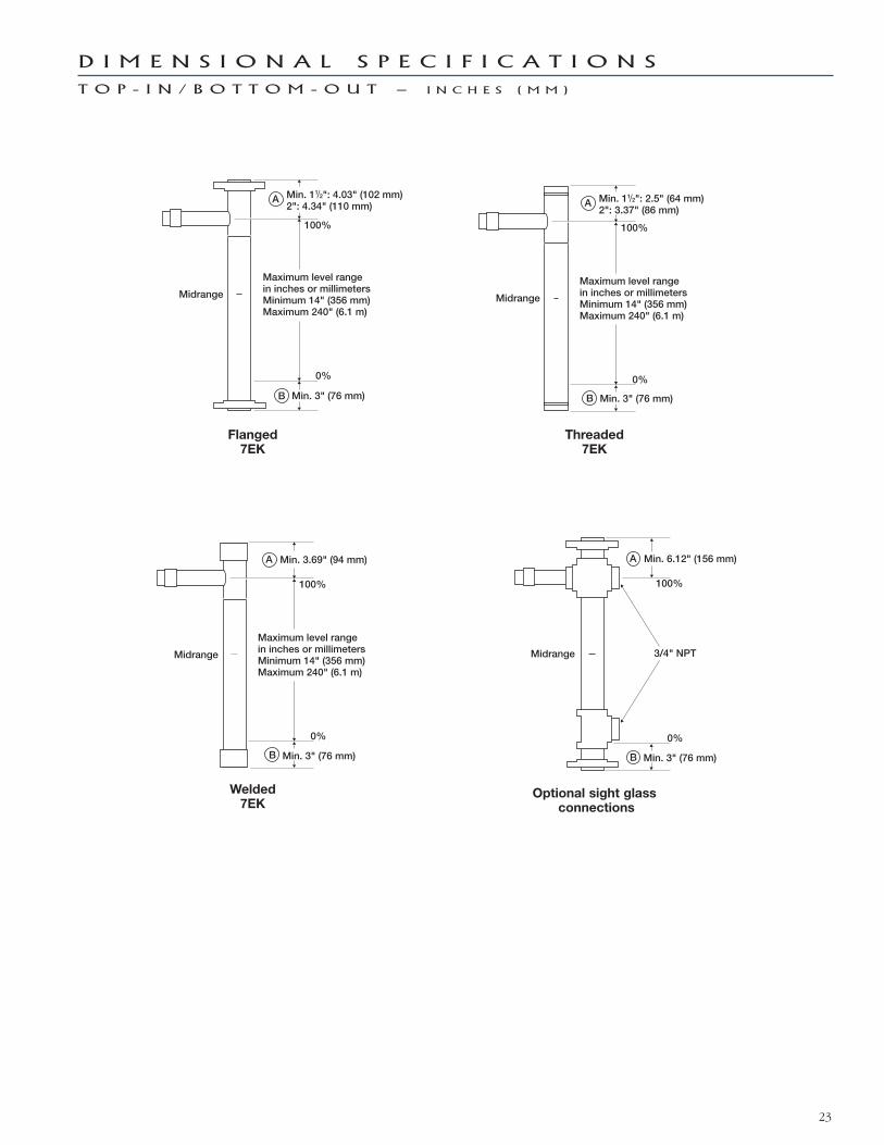
D I M E N S I O N A L S P E C I F I C A T I O N S
T O P - I N / B O T T O M - O U T — I N C H E S ( M M )
23
Flanged 7EK
Threaded 7EK
Welded 7EK
Optional sight glassconnections
Min. 6.12" (156 mm)
Min. 3" (76 mm)
3/4" NPT
100%
0%
Midrange
A
B
Min. 11/2": 2.5" (64 mm)2": 3.37" (86 mm)
Min. 3" (76 mm)
Maximum level rangein inches or millimetersMinimum 14" (356 mm)Maximum 240" (6.1 m)
100%
0%
Midrange
A
B
Min. 3.69" (94 mm)
Min. 3" (76 mm)
Maximum level rangein inches or millimetersMinimum 14" (356 mm)Maximum 240" (6.1 m)
100%
0%
Midrange
A
B
Min. 11/2": 4.03" (102 mm)2": 4.34" (110 mm)
Min. 3" (76 mm)
Maximum level rangein inches or millimetersMinimum 14" (356 mm)Maximum 240" (6.1 m)
100%
0%
Midrange
A
B

The quality assurance system in place at
MAGNETROL guarantees the highest level
of quality throughout the company.
MAGNETROL is committed to providing
full customer satisfaction both in quality
products and quality service.
The MAGNETROL quality assurance system
is registered to ISO 9001 affirming its com-
mitment to known international quality
standards providing the strongest assurance
of product/service quality available.
Several models of ECLIPSE Guided Wave
Radar Transmitters are available for quick
shipment, usually within one week after
factory receipt of a complete purchase order,
through the Expedite Ship Plan (ESP).
Models covered by ESP service are color
coded in the selection data charts.
To take advantage of ESP, simply match the
color coded model number codes (standard
dimensions apply).
ESP service may not apply to orders of ten
units or more. Contact your local representa-
tive for lead times on larger volume orders,
as well as other products and options.
EExpedite
SShipPPlan
All MAGNETROL electronic level and flow
controls are warranted free of defects in
materials or workmanship for one full year
from the date of original factory shipment.
If returned within the warranty period; and,
upon factory inspection of the control, the
cause of the claim is determined to be cov-
ered under the warranty; then, MAGNETROL
will repair or replace the control at no cost
to the purchaser (or owner) other than
transportation.
MAGNETROL shall not be liable for misap-
plication, labor claims, direct or consequential
damage or expense arising from the
installation or use of equipment. There are
no other warranties expressed or implied,
except special written warranties covering
some MAGNETROL products.
BULLETIN: 57-102.5EFFECTIVE: February 2012SUPERSEDES: January 2011
5300 Belmont Road • Downers Grove, Illinois 60515-4499 • 630-969-4000 • Fax 630-969-9489 • www.magnetrol.com145 Jardin Drive, Units 1 & 2 • Concord, Ontario Canada L4K 1X7 • 905-738-9600 • Fax 905-738-1306Heikensstraat 6 • B 9240 Zele, Belgium • 052 45.11.11 • Fax 052 45.09.93Regent Business Ctr., Jubilee Rd. • Burgess Hill, Sussex RH15 9TL U.K. • 01444-871313 • Fax 01444-871317
Copyright © 2012 Magnetrol International, Incorporated. All rights reserved. Printed in the USA.Performance specifications are effective with date of issue and are subject to change without notice.
For additional information, see Instruction Manual 57-600.
ECLIPSE Guided Wave Radar transmitters may be protected by one or more of the following U.S. Patent Nos. US 6,062,095:US 6,247,362; US 6,588,272; US 6,626,038; US 6,640,629; US 6,642,807; US 6,690,320; US 6,750,808; US 6,801,157; US 6,867,729; US 6,879,282; 6,906,662. May depend on model.
Q U A L I T Y
E S P
W A R R A N T Y
Magnetrol & Magnetrol logotype, Orion Instruments & Orion Instruments logotype, Eclipse, and Auroraare registered trademarks of Magnetrol International, Incorporated.HART® is a registered trademark of the HART Communication Foundation.Hastelloy® is a registered trademark of Haynes International.INCONEL® and Monel® are registered trademarks of the INCO family of companies.PEEK™ is a trademark of Vitrex plc.PROFIBUS is a registered trademark of PROFIBUS InternationalTeflon® is a registered trademark of DuPont.Viton® and Kalrez® are registered trademarks of DuPont Performance Elastomers.Masoneilan® is a registered trademark of Dresser Industries, Inc.Fisher® is a registered trademark of Emerson Process Management.Eckardt® is a registered trademark of Invensys Process Systems.Tokyo Keiso® is a registered trademark of Tokyo Keiso Co., Ltd.