Embed Size (px)
Citation preview
8/6/2019 Echo Wave Manual En
http://slidepdf.com/reader/full/echo-wave-manual-en 1/70
TELEMED ECHO WAVE ULTRASOUND SOFTWARE Operation Manual, Rev 2.7, 2006.02.10
1
ECHO WAVE
ULTRASOUND SOFTWAREFOR
ECHO BLASTER 64 AND ECHO BLASTER 128FAMILY SCANNERS
OPERATION MANUAL
8/6/2019 Echo Wave Manual En
http://slidepdf.com/reader/full/echo-wave-manual-en 2/70
TELEMED ECHO WAVE ULTRASOUND SOFTWARE Operation Manual, Rev 2.7, 2006.02.10
2
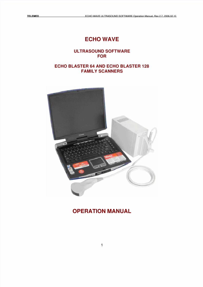
1. SYSTEM START-UP...............................................................................................4
1.1. Turning the system on .......................................................................................... 4
2. SOFTWARE MAIN CONTROLS.............................................................................6
2.1.1. Main controls................................................................................................ 6
2.1.2. Quick reference............................................................................................ 7
2.1.3. Ultrasound probe connecting or changing.................................................... 8
3. DETAILED DESCRIPTION .....................................................................................9
3.1. Scanning Controls................................................................................................. 9
3.1.1. Scan and Freeze modes.............................................................................. 9
3.1.2. Auto Freeze option....................................................................................... 9
3.1.3. Presets......................................................................................................... 9
3.1.4. Exiting from the program............................................................................ 10
3.1.5. B-mode control........................................................................................... 11
3.1.6. B/B-mode control ....................................................................................... 12
3.1.7. B/M-mode control....................................................................................... 13
3.1.8. M-mode control .......................................................................................... 14
3.1.9. Setting M-cursor for M-modes scanning .................................................... 15
3.1.10. Focusing control.................................................................................... 15
3.1.11. Depth control......................................................................................... 17
3.1.12. Scroll control.......................................................................................... 18
3.1.13. Zoom control ......................................................................................... 18
3.1.14. Scan Angle control................................................................................ 19
3.1.15. Cineloop control .................................................................................... 19
3.1.16. Scanning direction control..................................................................... 21
3.2. Preprocessing..................................................................................................... 22
3.2.1. Dynamic range control ............................................................................... 22 3.2.2. Power control............................................................................................. 23
3.2.3. Overall gain control.................................................................................... 23
3.2.4. Time gain compensation............................................................................ 23
3.2.5. Probe frequency......................................................................................... 24
3.3. Postprocessing ................................................................................................... 24
3.3.1. Image Enhancement control ...................................................................... 24
3.3.2. Frame Averaging control............................................................................ 25
3.3.3. Palette control ............................................................................................ 25
3.3.4. Advanced palette control............................................................................ 25
3.3.5. Rejection Filter........................................................................................... 27
3.3.6. Negative..................................................................................................... 28
3.4. Measurements .................................................................................................... 28
3.4.1. Measurements control................................................................................ 28
3.4.2. Linear measurements ................................................................................ 28
3.4.3. Angle measurements ................................................................................. 30
3.4.4. Perimeter and square measurements ........................................................ 31
3.4.5. Obstetric measurements packages............................................................ 32
3.4.6. Calculations on known dates of a pregnancy course ................................. 32
3.4.7. Calculations on fetus geometrical size ....................................................... 33
3.4.8. Fetus weight calculations........................................................................... 35
3.4.9. Managing obstetric calculations results...................................................... 37
8/6/2019 Echo Wave Manual En
http://slidepdf.com/reader/full/echo-wave-manual-en 3/70
TELEMED ECHO WAVE ULTRASOUND SOFTWARE Operation Manual, Rev 2.7, 2006.02.10
3
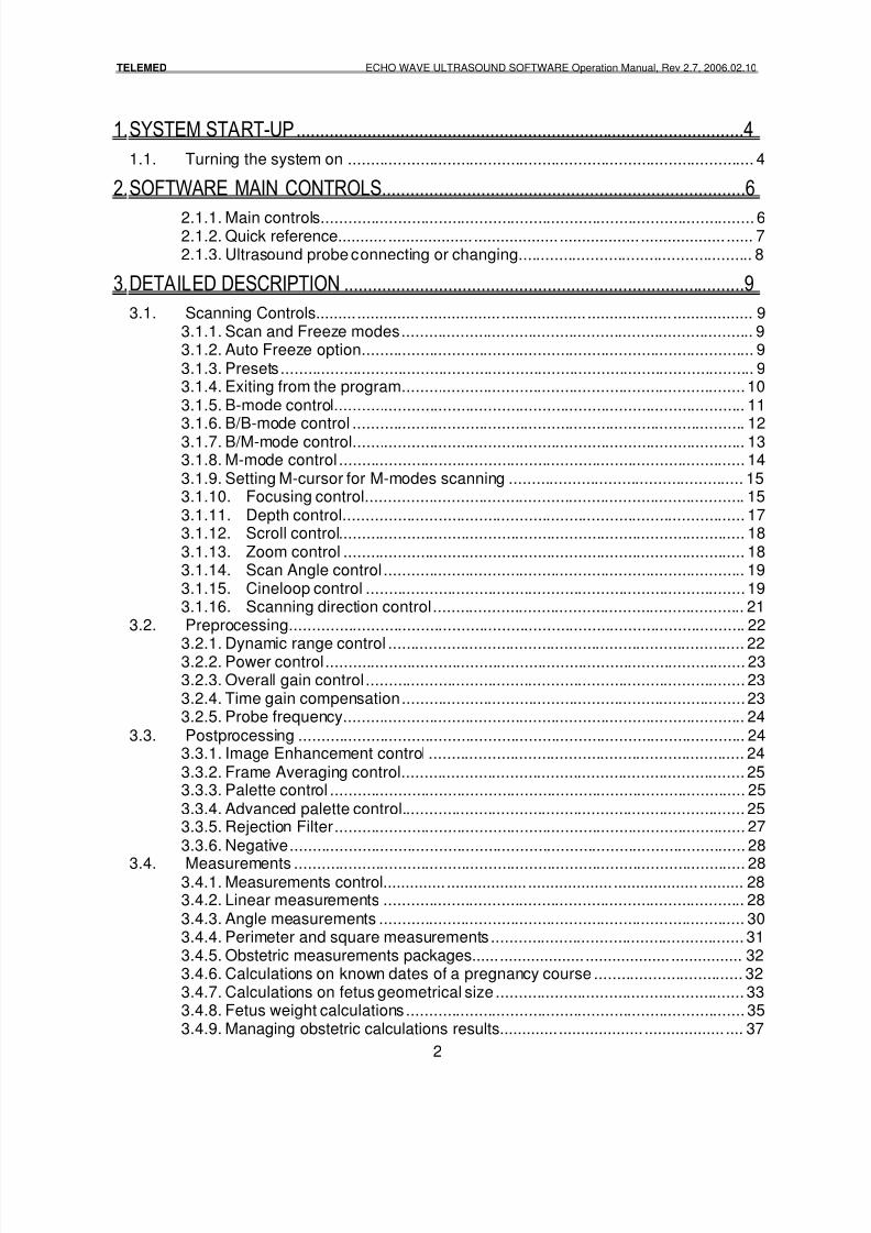
3.4.10. Urological measurements...................................................................... 38
3.4.11. Cardiology measurements and calculations.......................................... 40
3.4.12. Veterinarian Calculations ...................................................................... 44
3.4.13. Draw tools ............................................................................................. 45
3.4.14. Biopsy needle marker............................................................................ 47
3.5. Image management ............................................................................................ 49
3.5.1. Thumbnail mode ........................................................................................ 49
3.5.2. Saving to file .............................................................................................. 50
3.5.3. Quick Save option...................................................................................... 51
3.5.4. Loading from file ........................................................................................ 52
3.5.5. Direct e-mail sending ................................................................................. 54
3.5.6. External applications call list ...................................................................... 55
3.6. Reports ............................................................................................................... 56 3.6.1. Body Mark control ...................................................................................... 57
3.6.2. The comments to the patient examination ................................................. 58
3.6.3. Printing....................................................................................................... 60
3.7. Additional features .............................................................................................. 60
3.7.1. High Line Density....................................................................................... 61
3.7.2. Language selection.................................................................................... 61
3.7.3. Color schemes ........................................................................................... 62
3.7.4. Color schemes – Basics............................................................................. 62
3.7.5. Color schemes – Advanced ....................................................................... 63
3.7.6. Full Screen mode....................................................................................... 65
3.7.7. Test Mode.................................................................................................. 66
3.7.8. Calibrate Monitor........................................................................................ 68
3.7.9. Plug-Ins (Optional Software) ...................................................................... 69
4. REVISION HISTORY.............................................................................................70
ATTENTION:This manual is related to ECHO BLASTER 64 and ECHO BLASTER
128 family scanners.This description is based on ECHO BLASTER 128 scanner. Some
modes and features can be differ depends on connected model.This software can be used with LogicScan 64 or LogicScan 128
family scanners also, but in black and white modes only and withoutDoppler modes support. For Doppler modes together with LogicScan
family scanners use Echo Wave II software.
8/6/2019 Echo Wave Manual En
http://slidepdf.com/reader/full/echo-wave-manual-en 4/70
TELEMED ECHO WAVE ULTRASOUND SOFTWARE Operation Manual, Rev 2.7, 2006.02.10
4
1. SYSTEM START-UP
1.1. Turning the system on
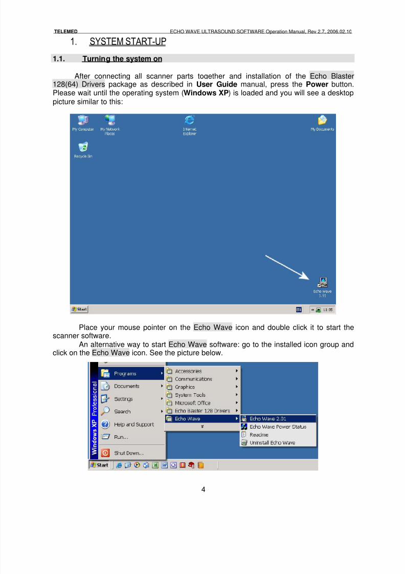
After connecting all scanner parts together and installation of the Echo Blaster128(64) Drivers package as described in User Guide manual, press the Power button.Please wait until the operating system (Windows XP) is loaded and you will see a desktop
picture similar to this:
Place your mouse pointer on the Echo Wave icon and double click it to start thescanner software.
An alternative way to start Echo Wave software: go to the installed icon group andclick on the Echo Wave icon. See the picture below.
8/6/2019 Echo Wave Manual En
http://slidepdf.com/reader/full/echo-wave-manual-en 5/70
TELEMED ECHO WAVE ULTRASOUND SOFTWARE Operation Manual, Rev 2.7, 2006.02.10
5
NOTE:Desktop view can differ from our example depending on the Windowstheme configuring.
8/6/2019 Echo Wave Manual En
http://slidepdf.com/reader/full/echo-wave-manual-en 6/70
TELEMED ECHO WAVE ULTRASOUND SOFTWARE Operation Manual, Rev 2.7, 2006.02.10
6
2. SOFTWARE MAIN CONTROLS
This chapter describes main controls.
2.1.1. Main controls
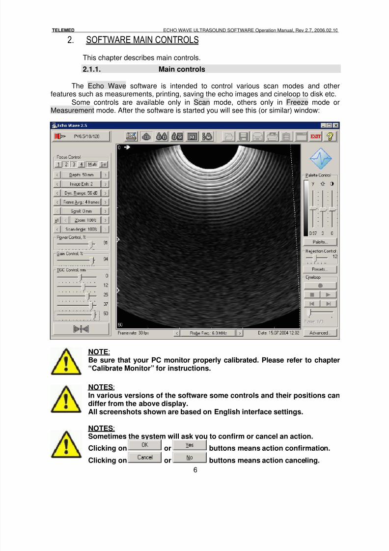
The Echo Wave software is intended to control various scan modes and other
features such as measurements, printing, saving the echo images and cineloop to disk etc.Some controls are available only in Scan mode, others only in Freeze mode orMeasurement mode. After the software is started you will see this (or similar) window:
NOTE:Be sure that your PC monitor properly calibrated. Please refer to chapter“Calibrate Monitor” for instructions.
NOTES:In various versions of the software some controls and their positions candiffer from the above display.All screenshots shown are based on English interface settings.
NOTES: Sometimes the system will ask you to confirm or cancel an action.
Clicking on or buttons means action confirmation.
Clicking on or buttons means action canceling.
8/6/2019 Echo Wave Manual En
http://slidepdf.com/reader/full/echo-wave-manual-en 7/70
TELEMED ECHO WAVE ULTRASOUND SOFTWARE Operation Manual, Rev 2.7, 2006.02.10
7
ESC button on keyboard means action canceling and closing drop-downmenu lists.
2.1.2. Quick reference
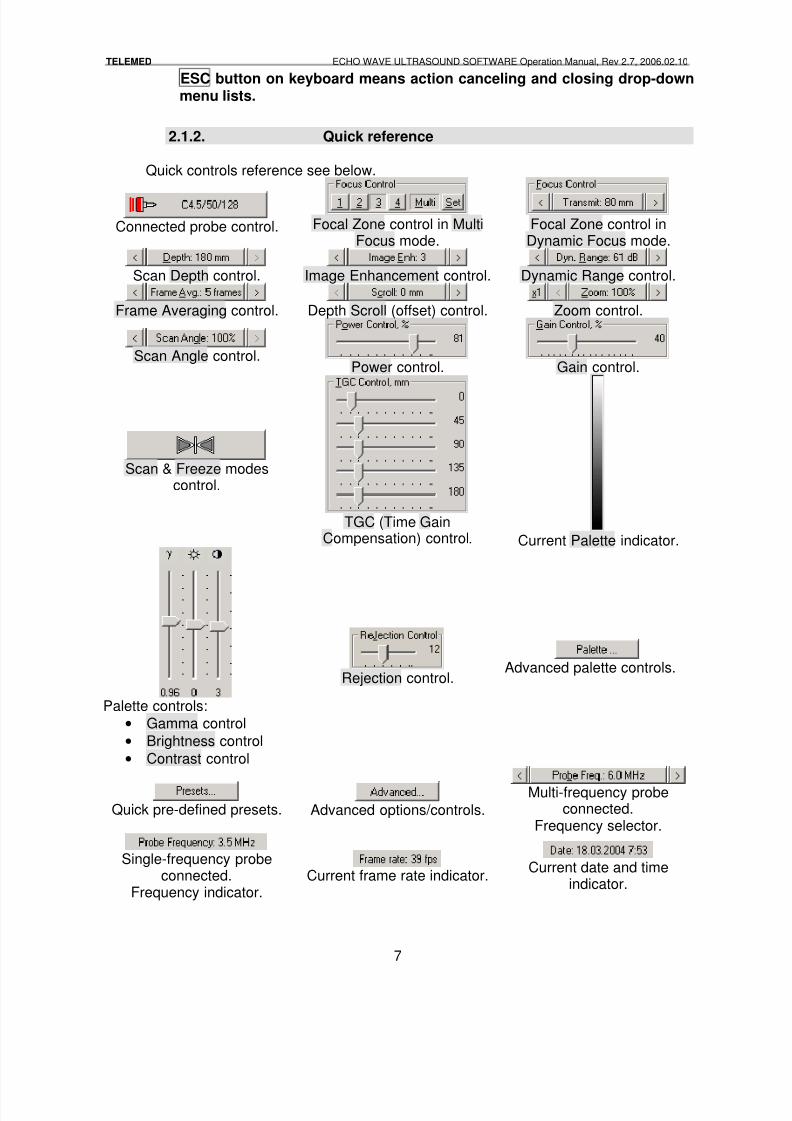
Quick controls reference see below.
Connected probe control. Focal Zone control in MultiFocus mode.
Focal Zone control inDynamic Focus mode.
Scan Depth control. Image Enhancement control. Dynamic Range control.
Frame Averaging control. Depth Scroll (offset) control. Zoom control.
Scan Angle control. Power control. Gain control.
Scan & Freeze modescontrol.
TGC (Time GainCompensation) control. Current Palette indicator.
Palette controls:
• Gamma control
• Brightness control
• Contrast control
Rejection control.Advanced palette controls.
Quick pre-defined presets. Advanced options/controls.
Multi-frequency probeconnected.
Frequency selector.
Single-frequency probeconnected.
Frequency indicator.Current frame rate indicator.
Current date and timeindicator.
8/6/2019 Echo Wave Manual En
http://slidepdf.com/reader/full/echo-wave-manual-en 8/70
TELEMED ECHO WAVE ULTRASOUND SOFTWARE Operation Manual, Rev 2.7, 2006.02.10
8
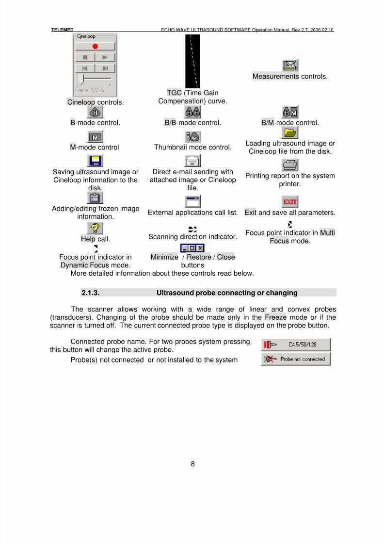
Cineloop controls.TGC (Time GainCompensation) curve.
Measurements controls.
B-mode control. B/B-mode control. B/M-mode control.
M-mode control. Thumbnail mode control. Loading ultrasound image orCineloop file from the disk.
Saving ultrasound image orCineloop information to the
disk.
Direct e-mail sending withattached image or Cineloop
file.
Printing report on the systemprinter.
Adding/editing frozen imageinformation.
External applications call list. Exit and save all parameters.
Help call. Scanning direction indicator.Focus point indicator in Multi
Focus mode.
Focus point indicator inDynamic Focus mode.
Minimize / Restore / Closebuttons
More detailed information about these controls read below.
2.1.3. Ultrasound probe connecting or changing
The scanner allows working with a wide range of linear and convex probes(transducers). Changing of the probe should be made only in the Freeze mode or if thescanner is turned off. The current connected probe type is displayed on the probe button.
Connected probe name. For two probes system pressingthis button will change the active probe.
Probe(s) not connected or not installed to the system
8/6/2019 Echo Wave Manual En
http://slidepdf.com/reader/full/echo-wave-manual-en 9/70
TELEMED ECHO WAVE ULTRASOUND SOFTWARE Operation Manual, Rev 2.7, 2006.02.10
9
3. DETAILED DESCRIPTION
3.1. Scanning Controls
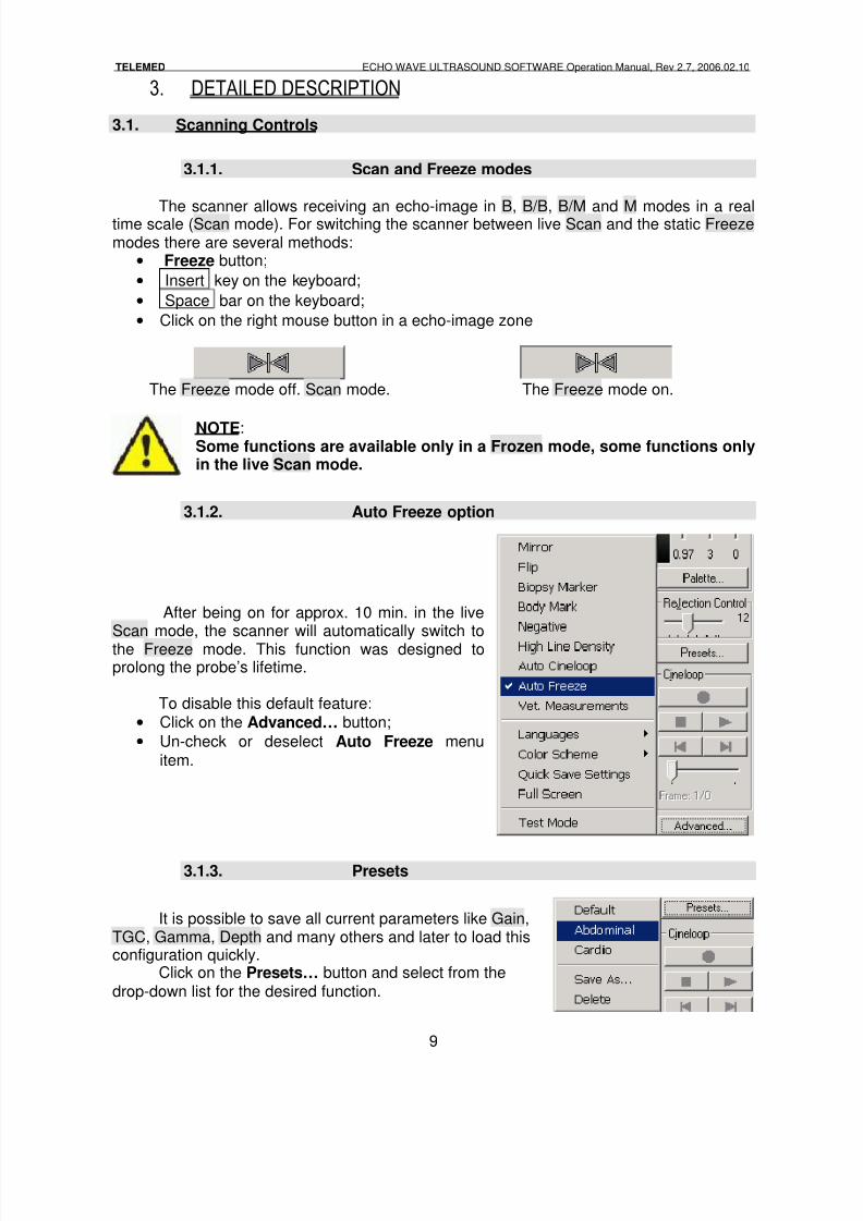
3.1.1. Scan and Freeze modes
The scanner allows receiving an echo-image in B, B/B, B/M and M modes in a realtime scale (Scan mode). For switching the scanner between live Scan and the static Freezemodes there are several methods:
• Freeze button;
• Insert key on the keyboard;
• Space bar on the keyboard;
• Click on the right mouse button in a echo-image zone
The Freeze mode off. Scan mode. The Freeze mode on.
NOTE:Some functions are available only in a Frozen mode, some functions onlyin the live Scan mode.
3.1.2. Auto Freeze option
3.1.3. Presets
It is possible to save all current parameters like Gain,TGC, Gamma, Depth and many others and later to load thisconfiguration quickly.
Click on the Presets… button and select from thedrop-down list for the desired function.
After being on for approx. 10 min. in the liveScan mode, the scanner will automatically switch tothe Freeze mode. This function was designed toprolong the probe’s lifetime.
To disable this default feature:
• Click on the Advanced… button;
• Un-check or deselect Auto Freeze menuitem.
8/6/2019 Echo Wave Manual En
http://slidepdf.com/reader/full/echo-wave-manual-en 10/70
TELEMED ECHO WAVE ULTRASOUND SOFTWARE Operation Manual, Rev 2.7, 2006.02.10
10
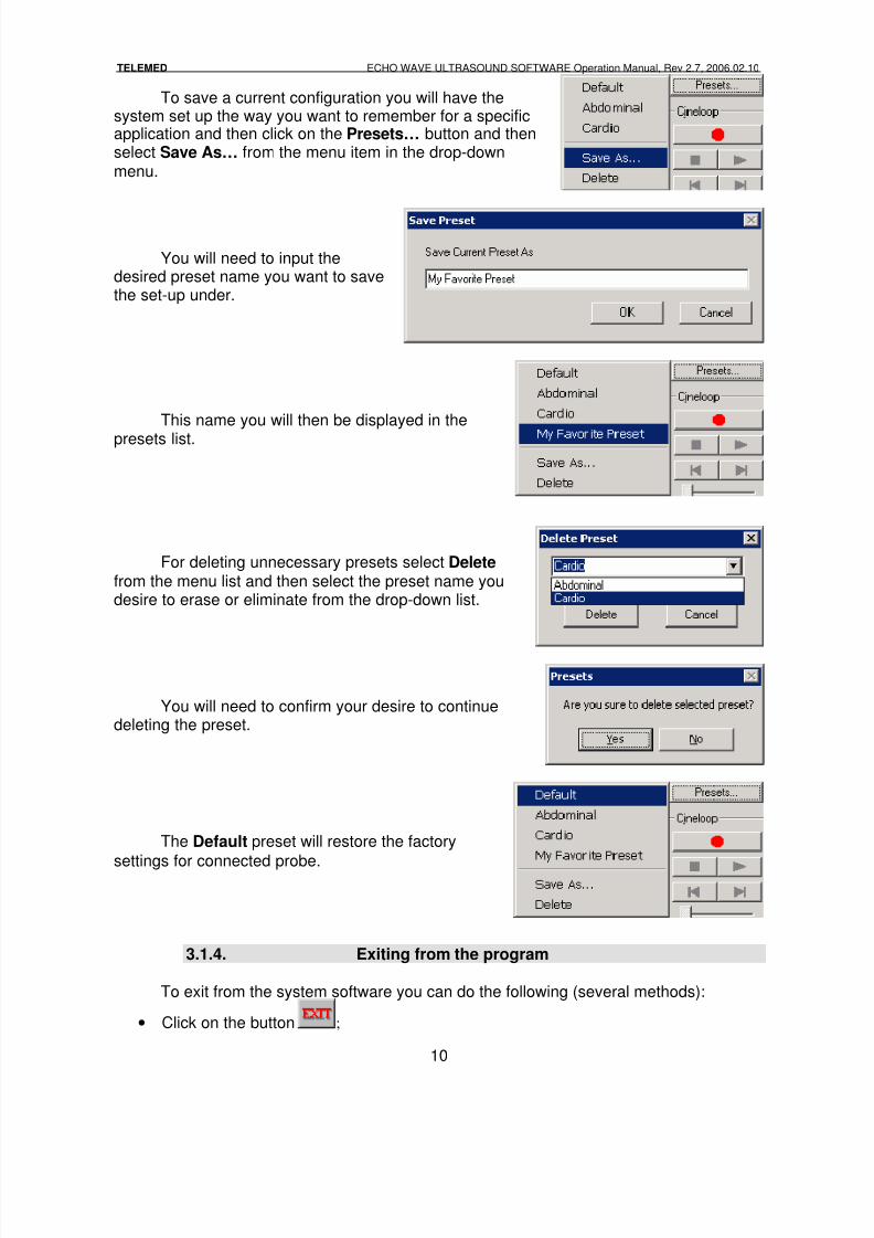
To save a current configuration you will have thesystem set up the way you want to remember for a specificapplication and then click on the Presets… button and thenselect Save As… from the menu item in the drop-downmenu.
You will need to input thedesired preset name you want to savethe set-up under.
This name you will then be displayed in the
presets list.
For deleting unnecessary presets select Delete from the menu list and then select the preset name youdesire to erase or eliminate from the drop-down list.
You will need to confirm your desire to continuedeleting the preset.
The Default preset will restore the factory
settings for connected probe.
3.1.4. Exiting from the program
To exit from the system software you can do the following (several methods):
• Click on the button ;
8/6/2019 Echo Wave Manual En
http://slidepdf.com/reader/full/echo-wave-manual-en 11/70
TELEMED ECHO WAVE ULTRASOUND SOFTWARE Operation Manual, Rev 2.7, 2006.02.10
11
• Click on the button;
• Hot key: F12 ;
• Hot key: Alt+F4
All current control states or setups (Gamma, Gain, TGC etc.) will be saved and willbe restored on the next program startup.
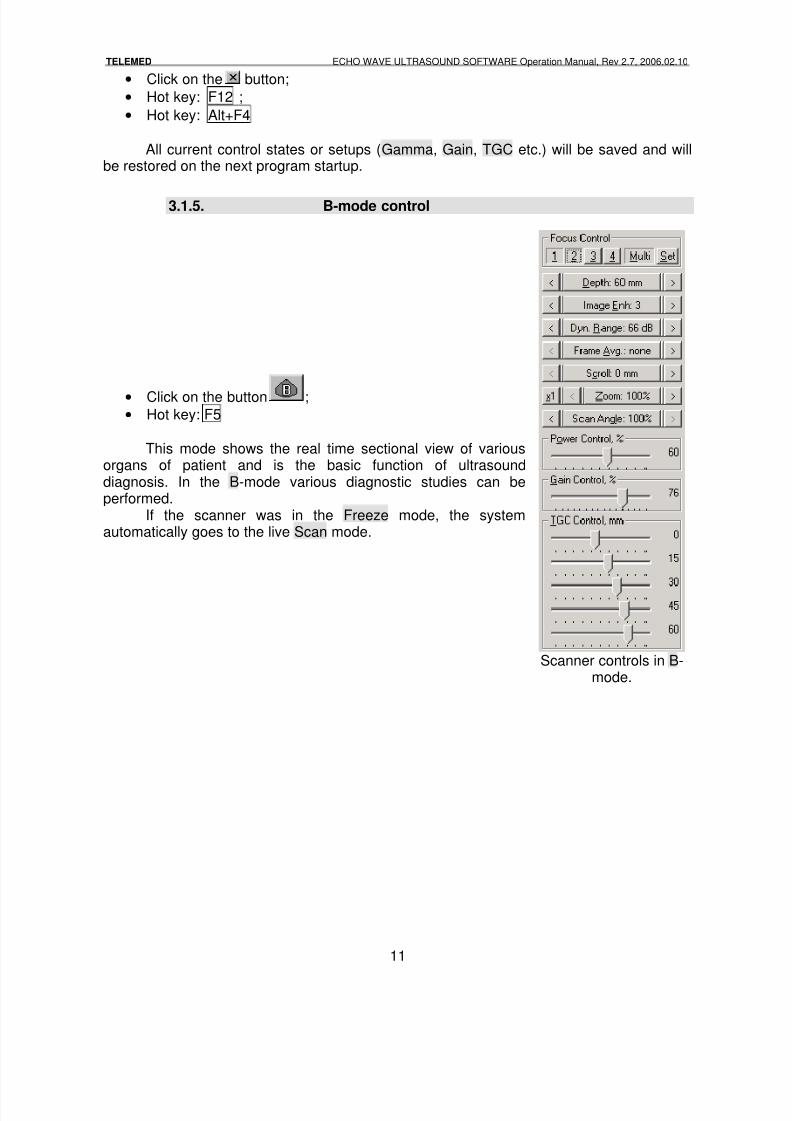
3.1.5. B-mode control
• Click on the button ;• Hot key: F5
This mode shows the real time sectional view of variousorgans of patient and is the basic function of ultrasounddiagnosis. In the B-mode various diagnostic studies can beperformed.
If the scanner was in the Freeze mode, the systemautomatically goes to the live Scan mode.
Scanner controls in B-mode.
8/6/2019 Echo Wave Manual En
http://slidepdf.com/reader/full/echo-wave-manual-en 12/70
TELEMED ECHO WAVE ULTRASOUND SOFTWARE Operation Manual, Rev 2.7, 2006.02.10
12
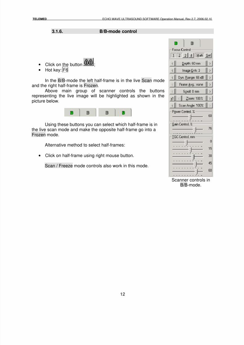
3.1.6. B/B-mode control
• Click on the button ;
• Hot key: F6
In the B/B-mode the left half-frame is in the live Scan modeand the right half-frame is Frozen.
Above main group of scanner controls the buttonsrepresenting the live image will be highlighted as shown in thepicture below.
Using these buttons you can select which half-frame is inthe live scan mode and make the opposite half-frame go into aFrozen mode.
Alternative method to select half-frames:
• Click on half-frame using right mouse button.
Scan / Freeze mode controls also work in this mode.
Scanner controls inB/B-mode.
8/6/2019 Echo Wave Manual En
http://slidepdf.com/reader/full/echo-wave-manual-en 13/70
TELEMED ECHO WAVE ULTRASOUND SOFTWARE Operation Manual, Rev 2.7, 2006.02.10
13
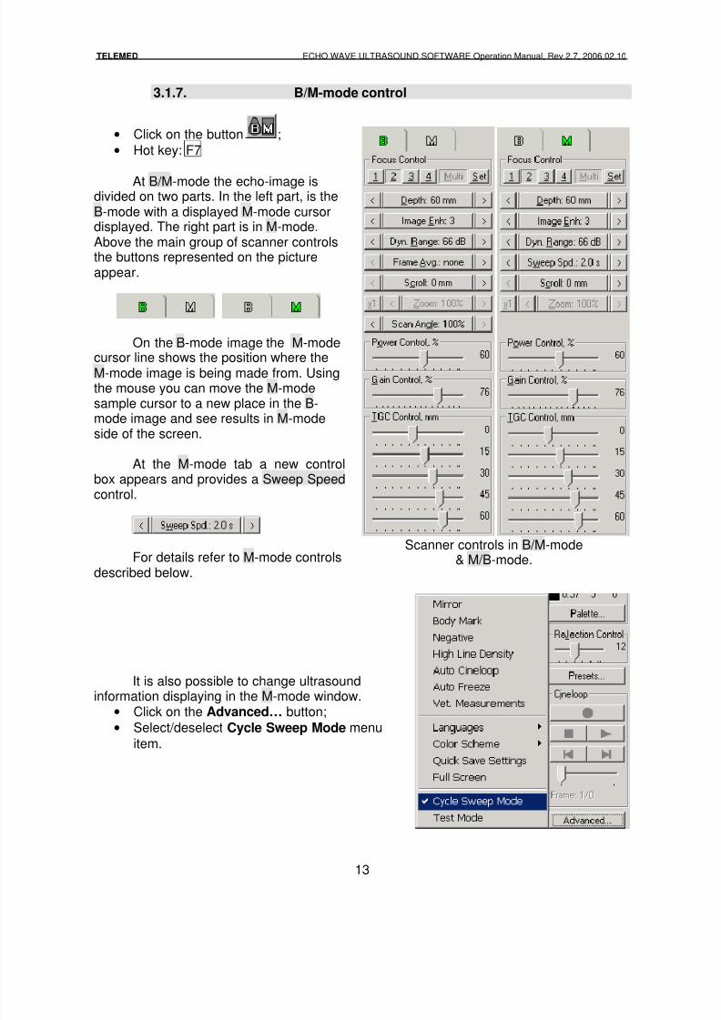
3.1.7. B/M-mode control
• Click on the button ;
• Hot key: F7
At B/M-mode the echo-image isdivided on two parts. In the left part, is theB-mode with a displayed M-mode cursordisplayed. The right part is in M-mode.Above the main group of scanner controlsthe buttons represented on the pictureappear.
On the B-mode image the M-mode
cursor line shows the position where theM-mode image is being made from. Usingthe mouse you can move the M-modesample cursor to a new place in the B-mode image and see results in M-modeside of the screen.
At the M-mode tab a new controlbox appears and provides a Sweep Speedcontrol.
For details refer to M-mode controlsdescribed below.
Scanner controls in B/M-mode& M/B-mode.
It is also possible to change ultrasoundinformation displaying in the M-mode window.
•Click on the Advanced… button;
• Select/deselect Cycle Sweep Mode menu
item.
8/6/2019 Echo Wave Manual En
http://slidepdf.com/reader/full/echo-wave-manual-en 14/70
TELEMED ECHO WAVE ULTRASOUND SOFTWARE Operation Manual, Rev 2.7, 2006.02.10
14
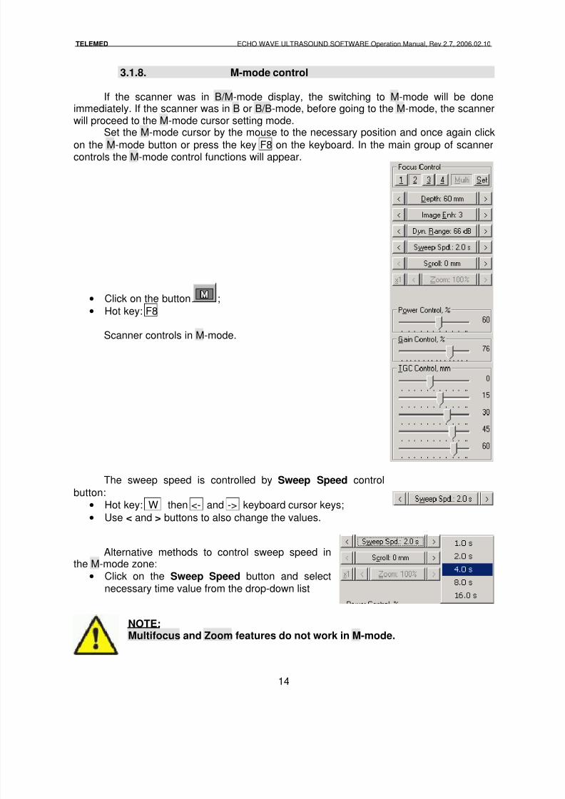
3.1.8. M-mode control
If the scanner was in B/M-mode display, the switching to M-mode will be doneimmediately. If the scanner was in B or B/B-mode, before going to the M-mode, the scannerwill proceed to the M-mode cursor setting mode.
Set the M-mode cursor by the mouse to the necessary position and once again click
on the M-mode button or press the key F8 on the keyboard. In the main group of scannercontrols the M-mode control functions will appear.
• Click on the button ;
• Hot key: F8
Scanner controls in M-mode.
The sweep speed is controlled by Sweep Speed control
button:
• Hot key: W then <- and -> keyboard cursor keys;
• Use < and > buttons to also change the values.
Alternative methods to control sweep speed inthe M-mode zone:
• Click on the Sweep Speed button and selectnecessary time value from the drop-down list
NOTE:Multifocus and Zoom features do not work in M-mode.
8/6/2019 Echo Wave Manual En
http://slidepdf.com/reader/full/echo-wave-manual-en 15/70
TELEMED ECHO WAVE ULTRASOUND SOFTWARE Operation Manual, Rev 2.7, 2006.02.10
15
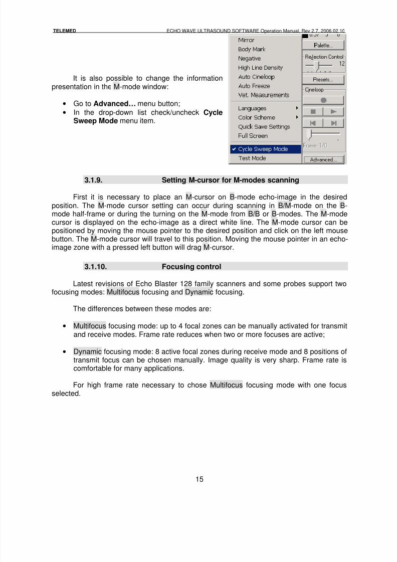
It is also possible to change the informationpresentation in the M-mode window:
• Go to Advanced… menu button;
• In the drop-down list check/uncheck CycleSweep Mode menu item.
3.1.9. Setting M-cursor for M-modes scanning
First it is necessary to place an M-cursor on B-mode echo-image in the desiredposition. The M-mode cursor setting can occur during scanning in B/M-mode on the B-mode half-frame or during the turning on the M-mode from B/B or B-modes. The M-modecursor is displayed on the echo-image as a direct white line. The M-mode cursor can bepositioned by moving the mouse pointer to the desired position and click on the left mousebutton. The M-mode cursor will travel to this position. Moving the mouse pointer in an echo-image zone with a pressed left button will drag M-cursor.
3.1.10. Focusing control
Latest revisions of Echo Blaster 128 family scanners and some probes support two
focusing modes: Multifocus focusing and Dynamic focusing.
The differences between these modes are:
• Multifocus focusing mode: up to 4 focal zones can be manually activated for transmitand receive modes. Frame rate reduces when two or more focuses are active;
• Dynamic focusing mode: 8 active focal zones during receive mode and 8 positions oftransmit focus can be chosen manually. Image quality is very sharp. Frame rate iscomfortable for many applications.
For high frame rate necessary to chose Multifocus focusing mode with one focus
selected.
8/6/2019 Echo Wave Manual En
http://slidepdf.com/reader/full/echo-wave-manual-en 16/70
TELEMED ECHO WAVE ULTRASOUND SOFTWARE Operation Manual, Rev 2.7, 2006.02.10
16
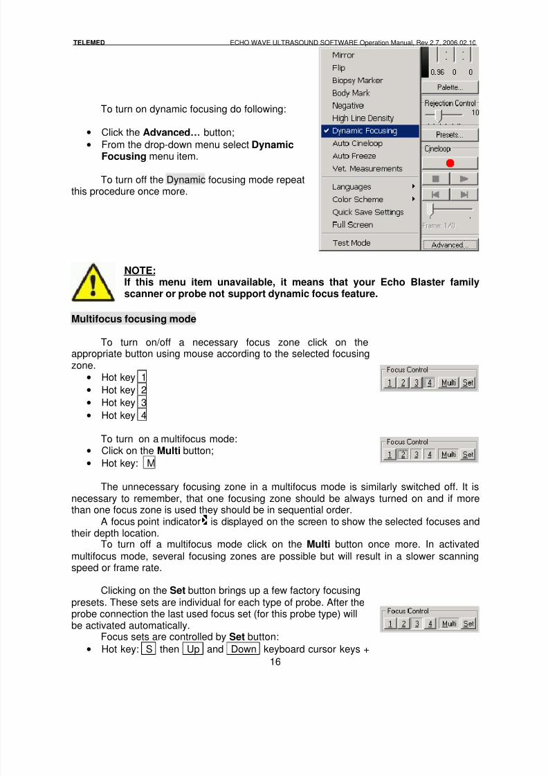
To turn on dynamic focusing do following:
•
Click the Advanced… button;• From the drop-down menu select Dynamic
Focusing menu item.
To turn off the Dynamic focusing mode repeatthis procedure once more.
NOTE:If this menu item unavailable, it means that your Echo Blaster familyscanner or probe not support dynamic focus feature.
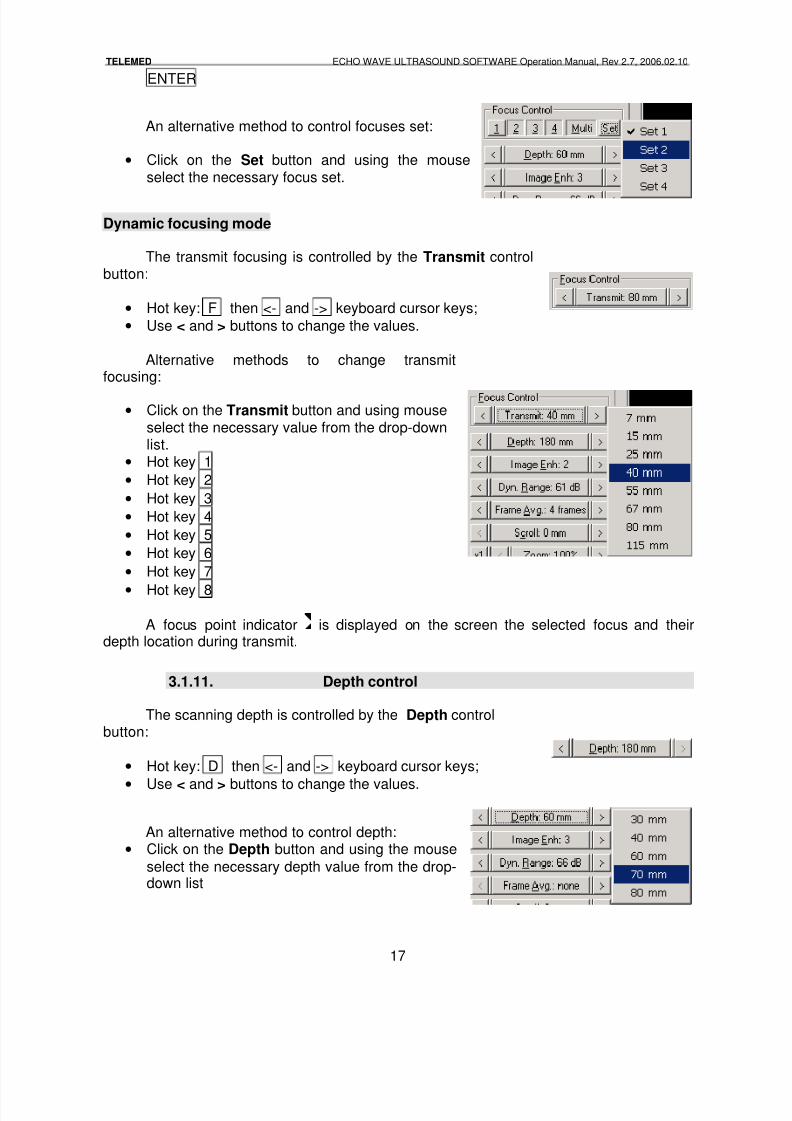
Multifocus focusing mode
To turn on/off a necessary focus zone click on theappropriate button using mouse according to the selected focusingzone.
• Hot key 1
• Hot key 2
•
Hot key 3• Hot key 4
To turn on a multifocus mode:• Click on the Multi button;
• Hot key: M
The unnecessary focusing zone in a multifocus mode is similarly switched off. It isnecessary to remember, that one focusing zone should be always turned on and if morethan one focus zone is used they should be in sequential order.
A focus point indicator is displayed on the screen to show the selected focuses andtheir depth location.
To turn off a multifocus mode click on the Multi button once more. In activatedmultifocus mode, several focusing zones are possible but will result in a slower scanningspeed or frame rate.
Clicking on the Set button brings up a few factory focusingpresets. These sets are individual for each type of probe. After theprobe connection the last used focus set (for this probe type) willbe activated automatically.
Focus sets are controlled by Set button:
• Hot key: S then Up and Down keyboard cursor keys +
8/6/2019 Echo Wave Manual En
http://slidepdf.com/reader/full/echo-wave-manual-en 17/70
TELEMED ECHO WAVE ULTRASOUND SOFTWARE Operation Manual, Rev 2.7, 2006.02.10
17
ENTER
An alternative method to control focuses set:
• Click on the Set button and using the mouseselect the necessary focus set.
Dynamic focusing mode
The transmit focusing is controlled by the Transmit controlbutton:
• Hot key: F then <- and -> keyboard cursor keys;
• Use < and > buttons to change the values.
Alternative methods to change transmitfocusing:
• Click on the Transmit button and using mouseselect the necessary value from the drop-downlist.
• Hot key 1
• Hot key 2
• Hot key 3
• Hot key 4
• Hot key 5
• Hot key 6
• Hot key 7
• Hot key 8
A focus point indicator is displayed on the screen the selected focus and theirdepth location during transmit.
3.1.11. Depth control
The scanning depth is controlled by the Depth controlbutton:
• Hot key: D then <- and -> keyboard cursor keys;
• Use < and > buttons to change the values.
An alternative method to control depth:• Click on the Depth button and using the mouse
select the necessary depth value from the drop-down list
8/6/2019 Echo Wave Manual En
http://slidepdf.com/reader/full/echo-wave-manual-en 18/70
TELEMED ECHO WAVE ULTRASOUND SOFTWARE Operation Manual, Rev 2.7, 2006.02.10
18
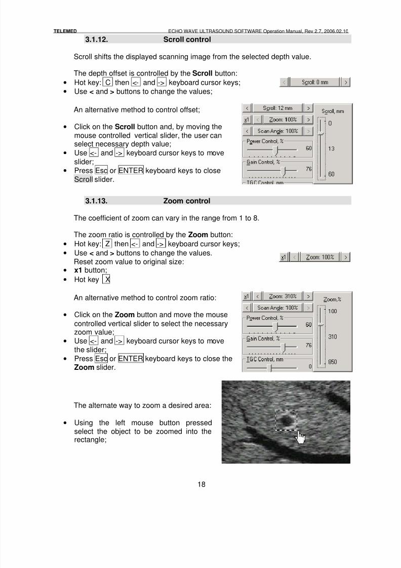
3.1.12. Scroll control
Scroll shifts the displayed scanning image from the selected depth value.
The depth offset is controlled by the Scroll button:
• Hot key: C then <- and -> keyboard cursor keys;
• Use < and > buttons to change the values;
An alternative method to control offset;
• Click on the Scroll button and, by moving themouse controlled vertical slider, the user canselect necessary depth value;
• Use <- and -> keyboard cursor keys to move
slider;• Press Esc or ENTER keyboard keys to close
Scroll slider.
3.1.13. Zoom control
The coefficient of zoom can vary in the range from 1 to 8.
The zoom ratio is controlled by the Zoom button:
• Hot key: Z then <- and -> keyboard cursor keys;
• Use < and > buttons to change the values.Reset zoom value to original size:
• x1 button;
• Hot key X
An alternative method to control zoom ratio:
• Click on the Zoom button and move the mouse
controlled vertical slider to select the necessaryzoom value;
• Use <- and -> keyboard cursor keys to movethe slider;
• Press Esc or ENTER keyboard keys to close theZoom slider.
The alternate way to zoom a desired area:
• Using the left mouse button pressedselect the object to be zoomed into therectangle;
8/6/2019 Echo Wave Manual En
http://slidepdf.com/reader/full/echo-wave-manual-en 19/70
TELEMED ECHO WAVE ULTRASOUND SOFTWARE Operation Manual, Rev 2.7, 2006.02.10
19
• Release the left mouse button and the
image inside the rectangle will be zoomed.
In the Zoom mode it is possible to change the rectangle position (window) insideecho-image. To change the position locate the mouse pointer above an echo-image andpress the left mouse button. Move the pointer above an echo-image pressing the left mousebutton. Move the mouse pointer and the zoomed echo-image area will move also. Release
the left mouse button.Zoom ratio in all zoom methods is indicated on the Zoom
control button.
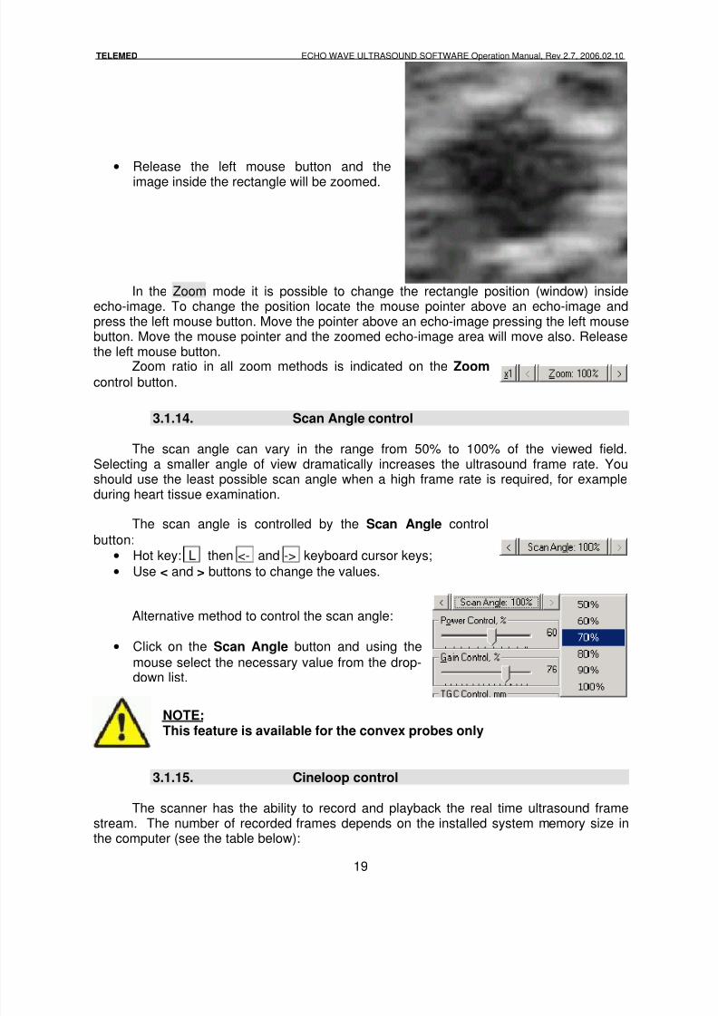
3.1.14. Scan Angle control
The scan angle can vary in the range from 50% to 100% of the viewed field.Selecting a smaller angle of view dramatically increases the ultrasound frame rate. Youshould use the least possible scan angle when a high frame rate is required, for exampleduring heart tissue examination.
The scan angle is controlled by the Scan Angle control
button:
• Hot key: L then <- and -> keyboard cursor keys;
• Use < and > buttons to change the values.
Alternative method to control the scan angle:
• Click on the Scan Angle button and using the
mouse select the necessary value from the drop-down list.
NOTE:This feature is available for the convex probes only
3.1.15. Cineloop control
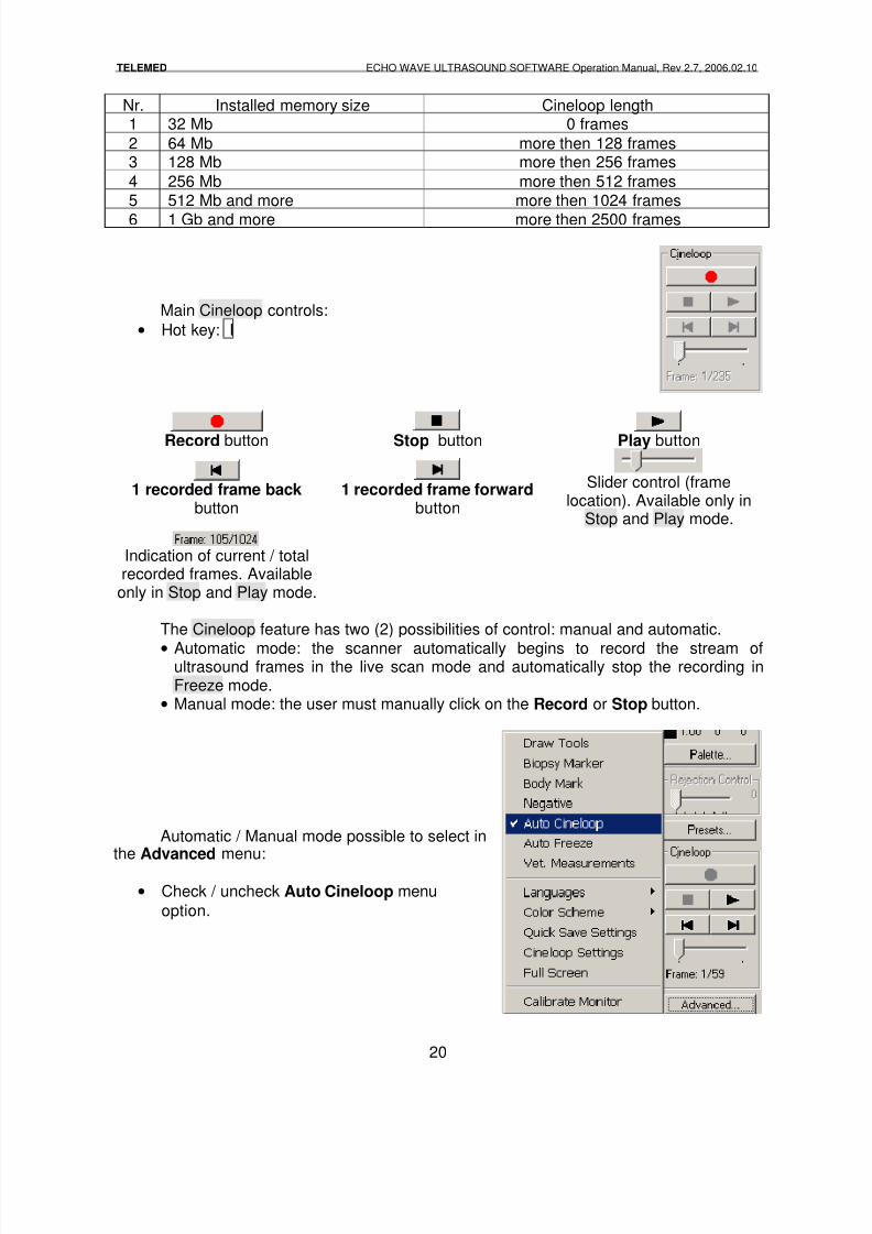
The scanner has the ability to record and playback the real time ultrasound framestream. The number of recorded frames depends on the installed system memory size inthe computer (see the table below):
8/6/2019 Echo Wave Manual En
http://slidepdf.com/reader/full/echo-wave-manual-en 20/70
TELEMED ECHO WAVE ULTRASOUND SOFTWARE Operation Manual, Rev 2.7, 2006.02.10
20
Nr. Installed memory size Cineloop length1 32 Mb 0 frames
2 64 Mb more then 128 frames3 128 Mb more then 256 frames
4 256 Mb more then 512 frames5 512 Mb and more more then 1024 frames
6 1 Gb and more more then 2500 frames
Main Cineloop controls:
• Hot key: I
Record button Stop button Play button
1 recorded frame back button
1 recorded frame forward button
Slider control (framelocation). Available only in
Stop and Play mode.
Indication of current / totalrecorded frames. Availableonly in Stop and Play mode.
The Cineloop feature has two (2) possibilities of control: manual and automatic.
• Automatic mode: the scanner automatically begins to record the stream ofultrasound frames in the live scan mode and automatically stop the recording inFreeze mode.
• Manual mode: the user must manually click on the Record or Stop button.
Automatic / Manual mode possible to select inthe Advanced menu:
• Check / uncheck Auto Cineloop menu
option.
8/6/2019 Echo Wave Manual En
http://slidepdf.com/reader/full/echo-wave-manual-en 21/70
TELEMED ECHO WAVE ULTRASOUND SOFTWARE Operation Manual, Rev 2.7, 2006.02.10
21
Cineloop recording is possible only in the live Scan mode and playback is possibleonly in the Freeze mode.
Recorded Cineloop contains all the scan parameters which were set beforerecording. It is not recommended to change the scan parameters during the Cinelooprecording. If you need to change some of the parameters then stop recording and changethe parameters before starting the recording again. If, during the Cineloop recording scanparameters were changed, Cineloop will contain the latest scan parameters values.
During playback Cineloop parameters are shown in the usual places. For example,the probe description is displayed on the probe control button; frame rate value is displayedat the bottom of the window and so on. Most of the parameters are shown at the scannercontrol panel of the main window.
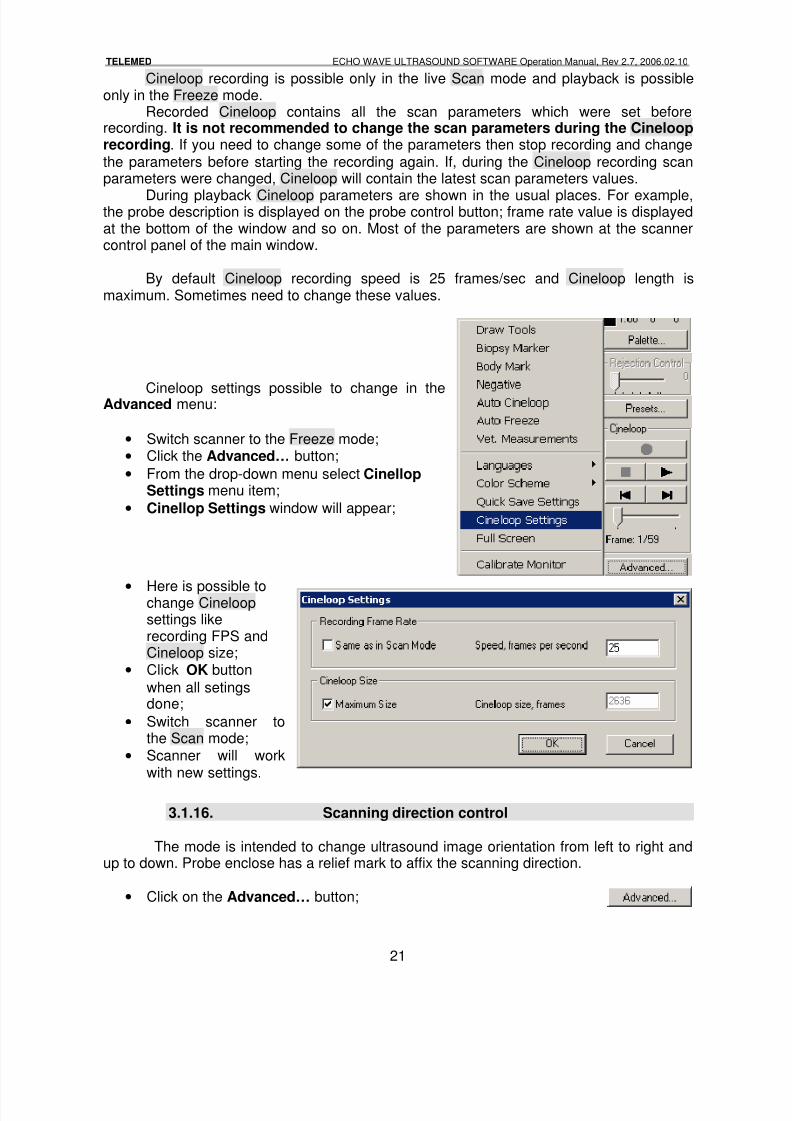
By default Cineloop recording speed is 25 frames/sec and Cineloop length ismaximum. Sometimes need to change these values.
Cineloop settings possible to change in theAdvanced menu:
• Switch scanner to the Freeze mode;• Click the Advanced… button;
• From the drop-down menu select CinellopSettings menu item;
• Cinellop Settings window will appear;
•Here is possible tochange Cineloopsettings likerecording FPS andCineloop size;
• Click OK button
when all setingsdone;
• Switch scanner tothe Scan mode;
• Scanner will workwith new settings.
3.1.16. Scanning direction control
The mode is intended to change ultrasound image orientation from left to right andup to down. Probe enclose has a relief mark to affix the scanning direction.
• Click on the Advanced… button;
8/6/2019 Echo Wave Manual En
http://slidepdf.com/reader/full/echo-wave-manual-en 22/70
TELEMED ECHO WAVE ULTRASOUND SOFTWARE Operation Manual, Rev 2.7, 2006.02.10
22
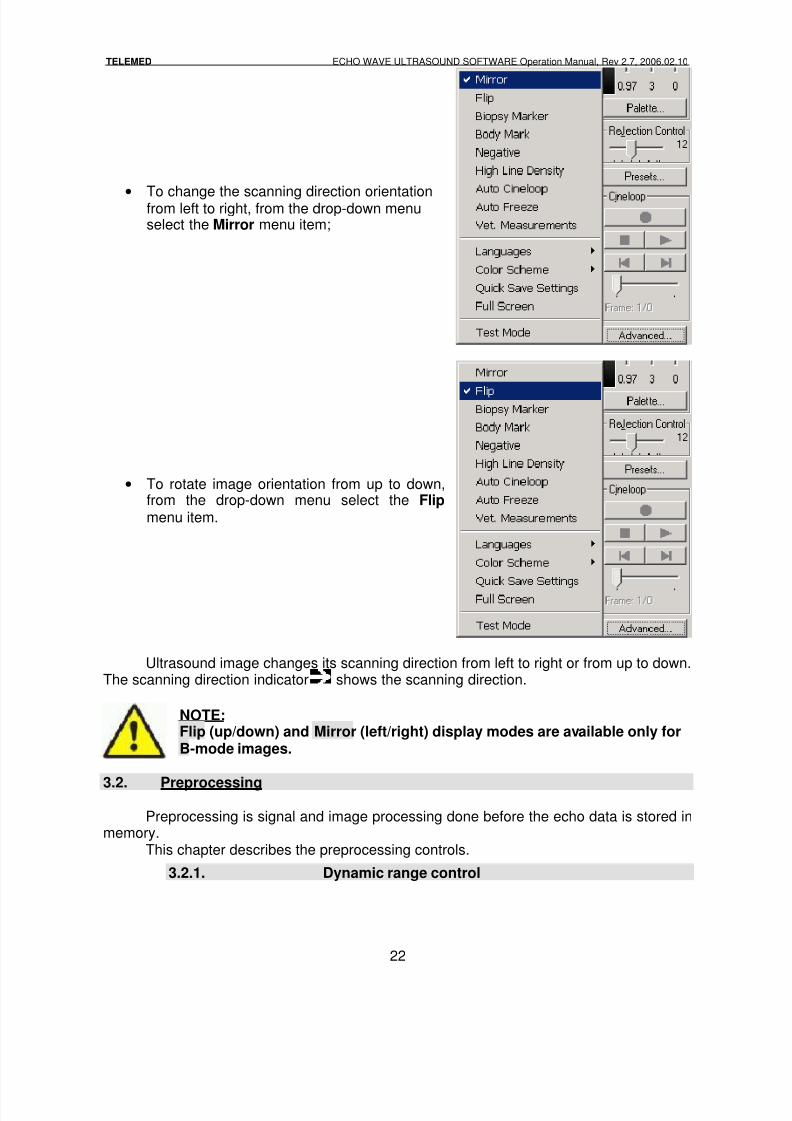
•
To change the scanning direction orientationfrom left to right, from the drop-down menuselect the Mirror menu item;
• To rotate image orientation from up to down,from the drop-down menu select the Flip menu item.
Ultrasound image changes its scanning direction from left to right or from up to down.The scanning direction indicator shows the scanning direction.
NOTE:Flip (up/down) and Mirror (left/right) display modes are available only forB-mode images.
3.2. Preprocessing
Preprocessing is signal and image processing done before the echo data is stored inmemory.
This chapter describes the preprocessing controls.
3.2.1. Dynamic range control
8/6/2019 Echo Wave Manual En
http://slidepdf.com/reader/full/echo-wave-manual-en 23/70
TELEMED ECHO WAVE ULTRASOUND SOFTWARE Operation Manual, Rev 2.7, 2006.02.10
23
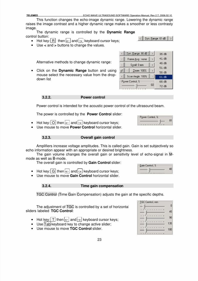
This function changes the echo-image dynamic range. Lowering the dynamic rangeraises the image contrast and a higher dynamic range makes a smoother or less contrastyimage.
The dynamic range is controlled by the Dynamic Range control button:
• Hot key: R then <- and -> keyboard cursor keys;
• Use < and > buttons to change the values.
Alternative methods to change dynamic range:
• Click on the Dynamic Range button and usingmouse select the necessary value from the drop-down list
3.2.2. Power control
Power control is intended for the acoustic power control of the ultrasound beam.
The power is controlled by the Power Control slider:
• Hot key: O then <- and -> keyboard cursor keys;
• Use mouse to move Power Control horizontal slider.
3.2.3. Overall gain control
Amplifiers increase voltage amplitudes. This is called gain. Gain is set subjectively soecho information appear with an appropriate or desired brightness.The gain volume changes the overall gain or sensitivity level of echo-signal in M-
mode as well as B-mode.The overall gain is controlled by Gain Control slider:
• Hot key: G then <- and -> keyboard cursor keys;
• Use mouse to move Gain Control horizontal slider.
3.2.4. Time gain compensation
TGC Control (Time Gain Compensation) adjusts the gain at the specific depths.
The adjustment of TGC is controlled by a set of horizontalsliders labeled TGC Control:
• Hot key: T then <- and -> keyboard cursor keys;
• Use Tab keyboard key to change active slider;
• Use mouse to move TGC Control slider.
8/6/2019 Echo Wave Manual En
http://slidepdf.com/reader/full/echo-wave-manual-en 24/70
TELEMED ECHO WAVE ULTRASOUND SOFTWARE Operation Manual, Rev 2.7, 2006.02.10
24
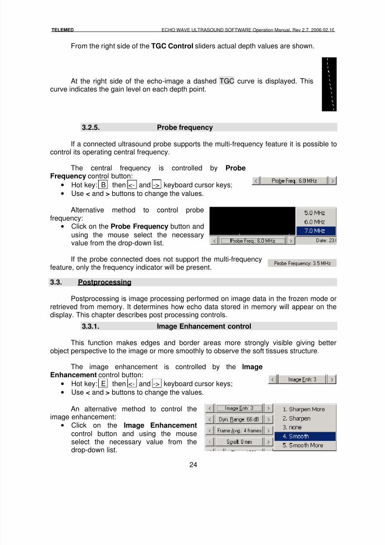
From the right side of the TGC Control sliders actual depth values are shown.
At the right side of the echo-image a dashed TGC curve is displayed. Thiscurve indicates the gain level on each depth point.
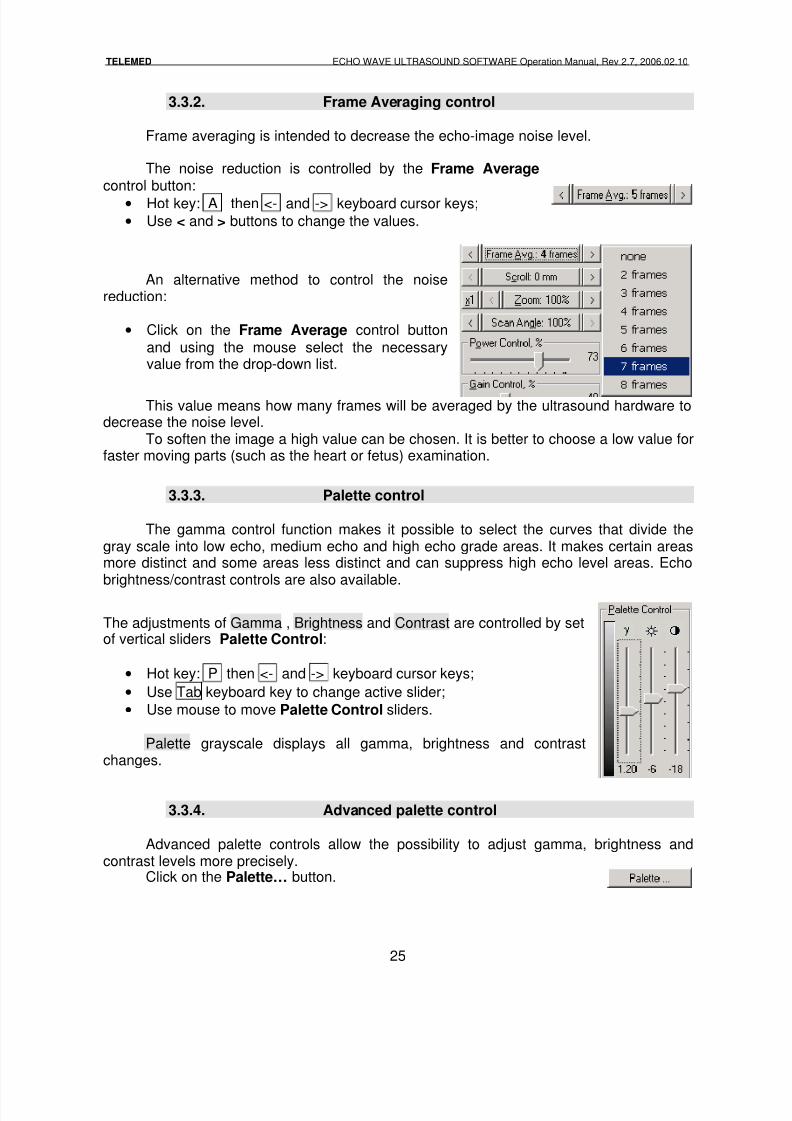
3.2.5. Probe frequency
If a connected ultrasound probe supports the multi-frequency feature it is possible tocontrol its operating central frequency.
The central frequency is controlled by ProbeFrequency control button:
• Hot key: B then <- and -> keyboard cursor keys;
• Use < and > buttons to change the values.
Alternative method to control probefrequency:
• Click on the Probe Frequency button and
using the mouse select the necessaryvalue from the drop-down list.
If the probe connected does not support the multi-frequencyfeature, only the frequency indicator will be present.
3.3. Postprocessing
Postprocessing is image processing performed on image data in the frozen mode orretrieved from memory. It determines how echo data stored in memory will appear on thedisplay. This chapter describes post processing controls.
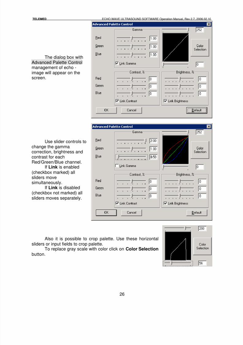
3.3.1. Image Enhancement control
This function makes edges and border areas more strongly visible giving betterobject perspective to the image or more smoothly to observe the soft tissues structure.
The image enhancement is controlled by the ImageEnhancement control button:
• Hot key: E then <- and -> keyboard cursor keys;• Use < and > buttons to change the values.
An alternative method to control theimage enhancement:
• Click on the Image Enhancement control button and using the mouseselect the necessary value from thedrop-down list.
8/6/2019 Echo Wave Manual En
http://slidepdf.com/reader/full/echo-wave-manual-en 25/70
TELEMED ECHO WAVE ULTRASOUND SOFTWARE Operation Manual, Rev 2.7, 2006.02.10
25
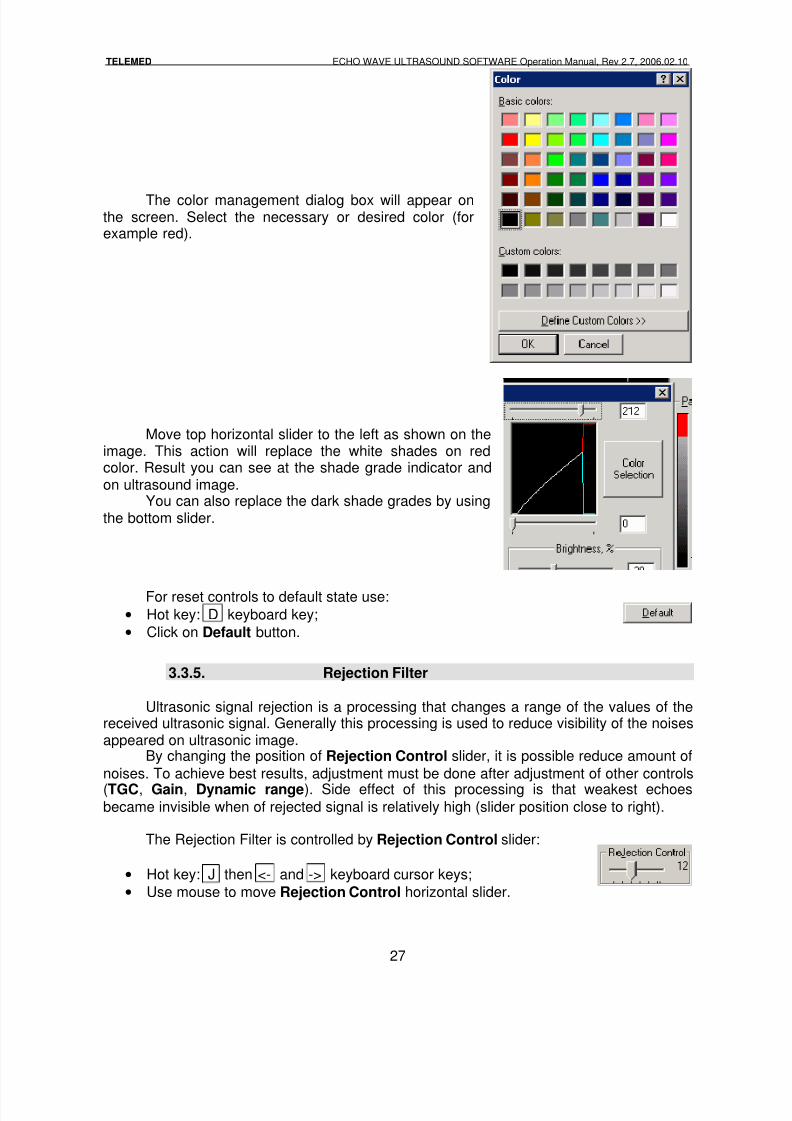
3.3.2. Frame Averaging control
Frame averaging is intended to decrease the echo-image noise level.
The noise reduction is controlled by the Frame Average control button:
• Hot key: A then <- and -> keyboard cursor keys;
• Use < and > buttons to change the values.
An alternative method to control the noisereduction:
• Click on the Frame Average control button
and using the mouse select the necessaryvalue from the drop-down list.
This value means how many frames will be averaged by the ultrasound hardware todecrease the noise level.
To soften the image a high value can be chosen. It is better to choose a low value forfaster moving parts (such as the heart or fetus) examination.
3.3.3. Palette control
The gamma control function makes it possible to select the curves that divide thegray scale into low echo, medium echo and high echo grade areas. It makes certain areasmore distinct and some areas less distinct and can suppress high echo level areas. Echobrightness/contrast controls are also available.
The adjustments of Gamma , Brightness and Contrast are controlled by setof vertical sliders Palette Control:
• Hot key: P then <- and -> keyboard cursor keys;
• Use Tab keyboard key to change active slider;
• Use mouse to move Palette Control sliders.
Palette grayscale displays all gamma, brightness and contrastchanges.
3.3.4. Advanced palette control
Advanced palette controls allow the possibility to adjust gamma, brightness andcontrast levels more precisely.
Click on the Palette… button.
8/6/2019 Echo Wave Manual En
http://slidepdf.com/reader/full/echo-wave-manual-en 26/70
TELEMED ECHO WAVE ULTRASOUND SOFTWARE Operation Manual, Rev 2.7, 2006.02.10
26
The dialog box withAdvanced Palette Controlmanagement of echo -image will appear on thescreen.
Use slider controls tochange the gammacorrection, brightness andcontrast for eachRed/Green/Blue channel.
If Link is enabled(checkbox marked) allsliders move
simultaneously.If Link is disabled
(checkbox not marked) allsliders moves separately.
Also it is possible to crop palette. Use these horizontalsliders or input fields to crop palette.
To replace gray scale with color click on Color Selection button.
8/6/2019 Echo Wave Manual En
http://slidepdf.com/reader/full/echo-wave-manual-en 27/70
TELEMED ECHO WAVE ULTRASOUND SOFTWARE Operation Manual, Rev 2.7, 2006.02.10
27
The color management dialog box will appear onthe screen. Select the necessary or desired color (forexample red).
Move top horizontal slider to the left as shown on theimage. This action will replace the white shades on redcolor. Result you can see at the shade grade indicator andon ultrasound image.
You can also replace the dark shade grades by usingthe bottom slider.
For reset controls to default state use:
• Hot key: D keyboard key;
• Click on Default button.
3.3.5. Rejection Filter
Ultrasonic signal rejection is a processing that changes a range of the values of thereceived ultrasonic signal. Generally this processing is used to reduce visibility of the noisesappeared on ultrasonic image.
By changing the position of Rejection Control slider, it is possible reduce amount of
noises. To achieve best results, adjustment must be done after adjustment of other controls
(TGC, Gain, Dynamic range). Side effect of this processing is that weakest echoesbecame invisible when of rejected signal is relatively high (slider position close to right).
The Rejection Filter is controlled by Rejection Control slider:
• Hot key: J then <- and -> keyboard cursor keys;
• Use mouse to move Rejection Control horizontal slider.
8/6/2019 Echo Wave Manual En
http://slidepdf.com/reader/full/echo-wave-manual-en 28/70
TELEMED ECHO WAVE ULTRASOUND SOFTWARE Operation Manual, Rev 2.7, 2006.02.10
28
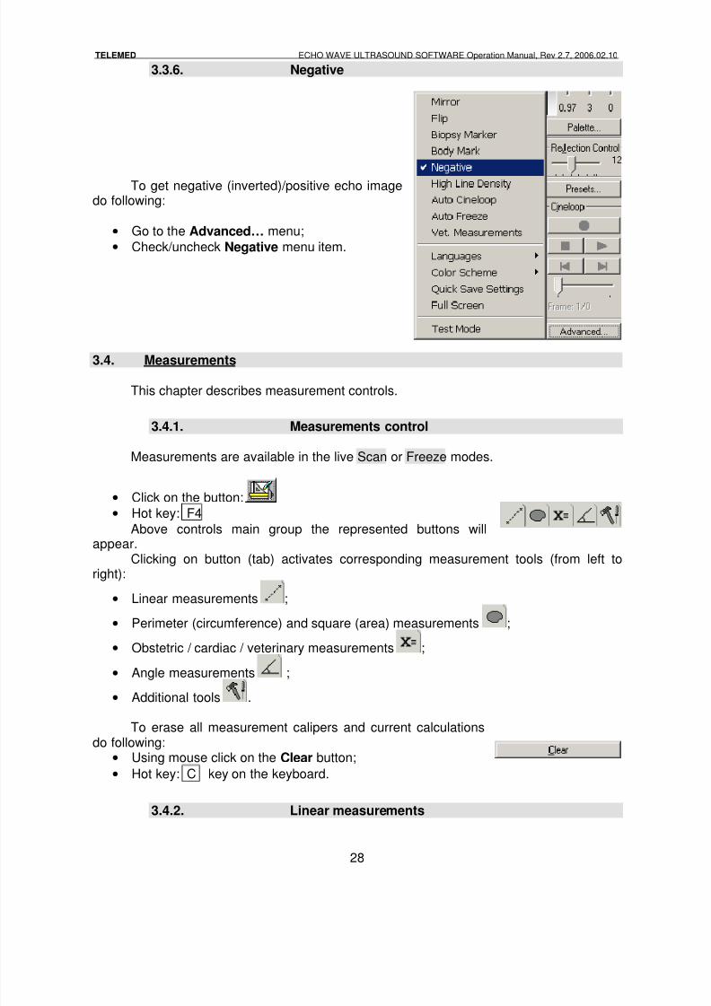
3.3.6. Negative
To get negative (inverted)/positive echo imagedo following:
• Go to the Advanced… menu;
• Check/uncheck Negative menu item.
3.4. Measurements
This chapter describes measurement controls.
3.4.1. Measurements control
Measurements are available in the live Scan or Freeze modes.
• Click on the button:
• Hot key: F4
Above controls main group the represented buttons willappear.
Clicking on button (tab) activates corresponding measurement tools (from left toright):
• Linear measurements ;
• Perimeter (circumference) and square (area) measurements ;
• Obstetric / cardiac / veterinary measurements ;
• Angle measurements ;
• Additional tools .
To erase all measurement calipers and current calculationsdo following:
• Using mouse click on the Clear button;
• Hot key: C key on the keyboard.
3.4.2. Linear measurements
8/6/2019 Echo Wave Manual En
http://slidepdf.com/reader/full/echo-wave-manual-en 29/70
TELEMED ECHO WAVE ULTRASOUND SOFTWARE Operation Manual, Rev 2.7, 2006.02.10
29
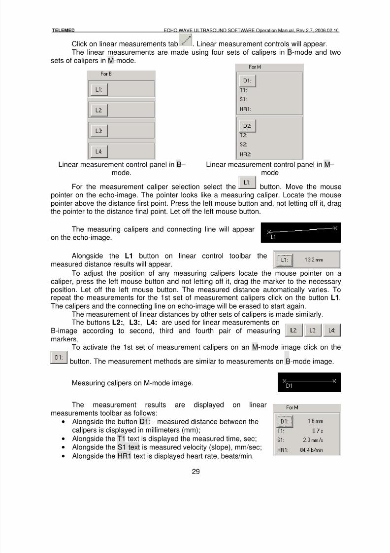
Click on linear measurements tab . Linear measurement controls will appear.The linear measurements are made using four sets of calipers in B-mode and two
sets of calipers in M-mode.
Linear measurement control panel in B– mode.
Linear measurement control panel in M– mode
For the measurement caliper selection select the button. Move the mouse
pointer on the echo-image. The pointer looks like a measuring caliper. Locate the mousepointer above the distance first point. Press the left mouse button and, not letting off it, dragthe pointer to the distance final point. Let off the left mouse button.
The measuring calipers and connecting line will appearon the echo-image.
Alongside the L1 button on linear control toolbar themeasured distance results will appear.
To adjust the position of any measuring calipers locate the mouse pointer on acaliper, press the left mouse button and not letting off it, drag the marker to the necessary
position. Let off the left mouse button. The measured distance automatically varies. Torepeat the measurements for the 1st set of measurement calipers click on the button L1.The calipers and the connecting line on echo-image will be erased to start again.
The measurement of linear distances by other sets of calipers is made similarly.The buttons L2:, L3:, L4: are used for linear measurements on
B-image according to second, third and fourth pair of measuringmarkers.
To activate the 1st set of measurement calipers on an M-mode image click on the
button. The measurement methods are similar to measurements on B-mode image.
Measuring calipers on M-mode image.
The measurement results are displayed on linearmeasurements toolbar as follows:
• Alongside the button D1: - measured distance between thecalipers is displayed in millimeters (mm);
• Alongside the T1 text is displayed the measured time, sec;
• Alongside the S1 text is measured velocity (slope), mm/sec;
• Alongside the HR1 text is displayed heart rate, beats/min.
8/6/2019 Echo Wave Manual En
http://slidepdf.com/reader/full/echo-wave-manual-en 30/70
TELEMED ECHO WAVE ULTRASOUND SOFTWARE Operation Manual, Rev 2.7, 2006.02.10
30
The linear measurement activation on an M-mode image by the second set ofcalipers is made similarly. The button D2: is used for the second pair of calipers.
3.4.3. Angle measurements
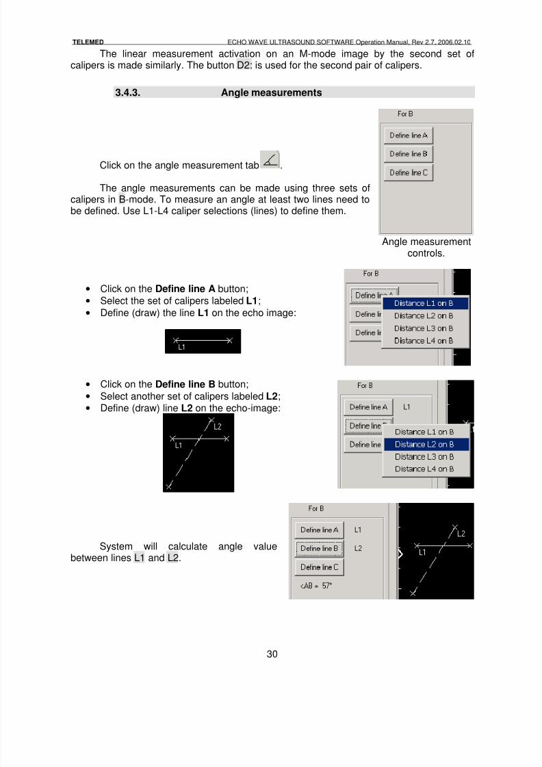
Click on the angle measurement tab .
The angle measurements can be made using three sets ofcalipers in B-mode. To measure an angle at least two lines need tobe defined. Use L1-L4 caliper selections (lines) to define them.
Angle measurementcontrols.
• Click on the Define line A button;
• Select the set of calipers labeled L1;
• Define (draw) the line L1 on the echo image:
• Click on the Define line B button;
• Select another set of calipers labeled L2;• Define (draw) line L2 on the echo-image:
System will calculate angle valuebetween lines L1 and L2.
8/6/2019 Echo Wave Manual En
http://slidepdf.com/reader/full/echo-wave-manual-en 31/70
TELEMED ECHO WAVE ULTRASOUND SOFTWARE Operation Manual, Rev 2.7, 2006.02.10
31
NOTE:If appropriate lines are already defined, the results of the anglemeasurements are displayed immediately. If they are not defined yet, thenthe results are being calculated dynamically during the defining.
3.4.4. Perimeter and square measurements
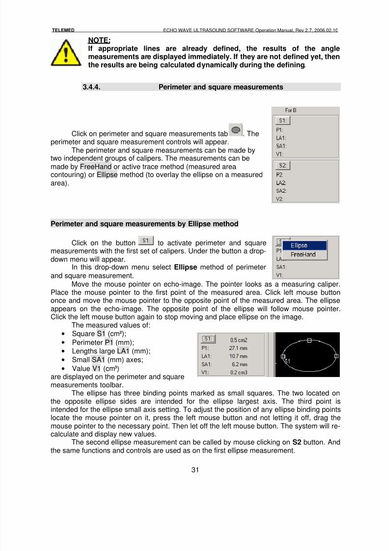
Click on perimeter and square measurements tab . Theperimeter and square measurement controls will appear.
The perimeter and square measurements can be made bytwo independent groups of calipers. The measurements can bemade by FreeHand or active trace method (measured areacontouring) or Ellipse method (to overlay the ellipse on a measuredarea).
Perimeter and square measurements by Ellipse method
Click on the button to activate perimeter and squaremeasurements with the first set of calipers. Under the button a drop-down menu will appear.
In this drop-down menu select Ellipse method of perimeter
and square measurement.Move the mouse pointer on echo-image. The pointer looks as a measuring caliper.
Place the mouse pointer to the first point of the measured area. Click left mouse buttononce and move the mouse pointer to the opposite point of the measured area. The ellipseappears on the echo-image. The opposite point of the ellipse will follow mouse pointer.Click the left mouse button again to stop moving and place ellipse on the image.
The measured values of:
• Square S1 (cm²);
• Perimeter Р1 (mm);
• Lengths large LA1 (mm);
• Small SA1 (mm) axes;
• Value V1 (cm³)are displayed on the perimeter and square
measurements toolbar.The ellipse has three binding points marked as small squares. The two located on
the opposite ellipse sides are intended for the ellipse largest axis. The third point isintended for the ellipse small axis setting. To adjust the position of any ellipse binding pointslocate the mouse pointer on it, press the left mouse button and not letting it off, drag themouse pointer to the necessary point. Then let off the left mouse button. The system will re-calculate and display new values.
The second ellipse measurement can be called by mouse clicking on S2 button. Andthe same functions and controls are used as on the first ellipse measurement.
8/6/2019 Echo Wave Manual En
http://slidepdf.com/reader/full/echo-wave-manual-en 32/70
TELEMED ECHO WAVE ULTRASOUND SOFTWARE Operation Manual, Rev 2.7, 2006.02.10
32
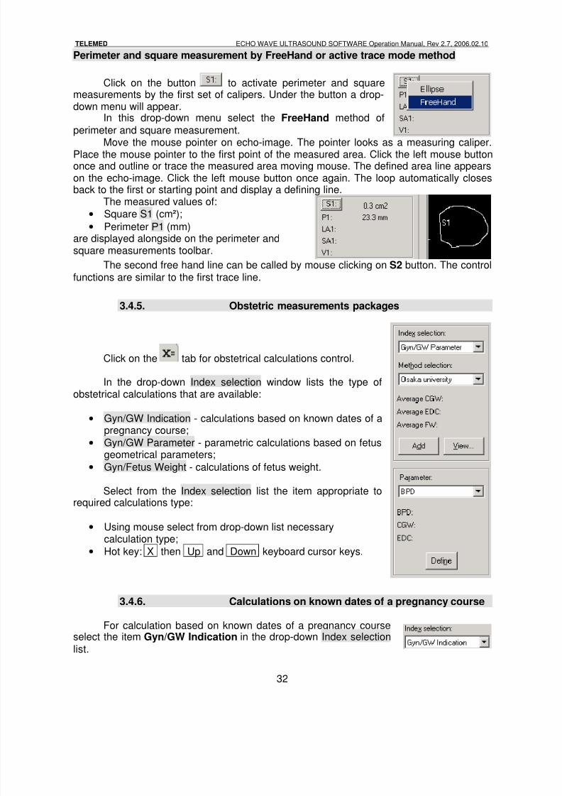
Perimeter and square measurement by FreeHand or active trace mode method
Click on the button to activate perimeter and squaremeasurements by the first set of calipers. Under the button a drop-down menu will appear.
In this drop-down menu select the FreeHand method of
perimeter and square measurement.
Move the mouse pointer on echo-image. The pointer looks as a measuring caliper.Place the mouse pointer to the first point of the measured area. Click the left mouse buttononce and outline or trace the measured area moving mouse. The defined area line appearson the echo-image. Click the left mouse button once again. The loop automatically closesback to the first or starting point and display a defining line.
The measured values of:
• Square S1 (cm²);
• Perimeter Р1 (mm)are displayed alongside on the perimeter andsquare measurements toolbar.
The second free hand line can be called by mouse clicking on S2 button. The control
functions are similar to the first trace line.
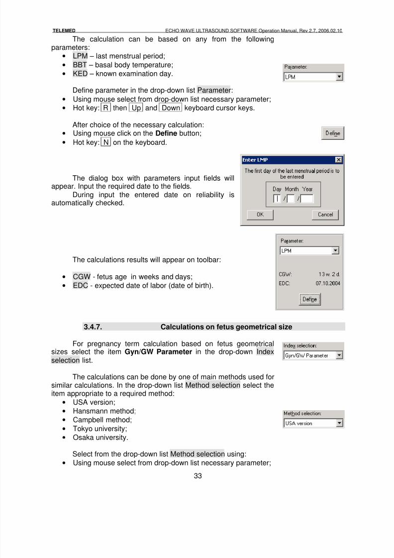
3.4.5. Obstetric measurements packages
Click on the tab for obstetrical calculations control.
In the drop-down Index selection window lists the type ofobstetrical calculations that are available:
• Gyn/GW Indication - calculations based on known dates of apregnancy course;
• Gyn/GW Parameter - parametric calculations based on fetusgeometrical parameters;
• Gyn/Fetus Weight - calculations of fetus weight.
Select from the Index selection list the item appropriate torequired calculations type:
• Using mouse select from drop-down list necessarycalculation type;
• Hot key: X then Up and Down keyboard cursor keys.
3.4.6. Calculations on known dates of a pregnancy course
For calculation based on known dates of a pregnancy courseselect the item Gyn/GW Indication in the drop-down Index selection
list.
8/6/2019 Echo Wave Manual En
http://slidepdf.com/reader/full/echo-wave-manual-en 33/70
TELEMED ECHO WAVE ULTRASOUND SOFTWARE Operation Manual, Rev 2.7, 2006.02.10
33
The calculation can be based on any from the followingparameters:
• LPM – last menstrual period;
• BBT – basal body temperature;
• KED – known examination day.
Define parameter in the drop-down list Parameter:
• Using mouse select from drop-down list necessary parameter;• Hot key: R then Up and Down keyboard cursor keys.
After choice of the necessary calculation:• Using mouse click on the Define button;
• Hot key: N on the keyboard.
The dialog box with parameters input fields willappear. Input the required date to the fields.
During input the entered date on reliability isautomatically checked.
The calculations results will appear on toolbar:
• CGW - fetus age in weeks and days;
• EDC - expected date of labor (date of birth).
3.4.7. Calculations on fetus geometrical size
For pregnancy term calculation based on fetus geometricalsizes select the item Gyn/GW Parameter in the drop-down Indexselection list.
The calculations can be done by one of main methods used forsimilar calculations. In the drop-down list Method selection select the
item appropriate to a required method:• USA version;
• Hansmann method;
• Campbell method;
• Tokyo university;
• Osaka university.
Select from the drop-down list Method selection using:
• Using mouse select from drop-down list necessary parameter;
8/6/2019 Echo Wave Manual En
http://slidepdf.com/reader/full/echo-wave-manual-en 34/70
TELEMED ECHO WAVE ULTRASOUND SOFTWARE Operation Manual, Rev 2.7, 2006.02.10
34
• Hot key: H then Up and Down keyboard cursor keys.
Calculation can be based on one of the following parameters:
• AC – Abdominal Circumference;
• BPD – Biparietal Diameter;
• CRL – Crown-Rump Length;
• FL – Femur Length;
• FTA – Fetal Trunk Cross-Sectional Area;• GS – Gestational Sac;
• HC – Head Circumference;
• HL – Humeral Length;
• LV – Length of Vertebrae.
For each selected method the list of possible parameters in thedrop-down list Parameter is shown. Select in this list item appropriateto the required parameter.
Select from the drop-down list Parameter using:
•Using mouse select from drop-down list necessary parameter;
• Hot key: R then Up and Down keyboard cursor keys.
After choice of the necessary parameter:
• Using mouse click on the Define button;
• Hot key: N on the keyboard.
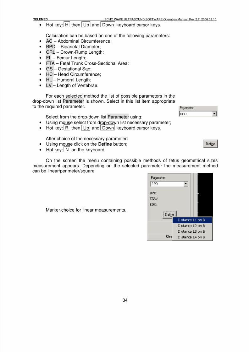
On the screen the menu containing possible methods of fetus geometrical sizesmeasurement appears. Depending on the selected parameter the measurement methodcan be linear/perimeter/square.
Marker choice for linear measurements.
8/6/2019 Echo Wave Manual En
http://slidepdf.com/reader/full/echo-wave-manual-en 35/70
TELEMED ECHO WAVE ULTRASOUND SOFTWARE Operation Manual, Rev 2.7, 2006.02.10
35
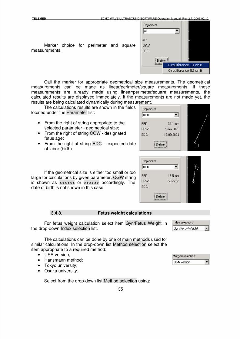
Marker choice for perimeter and squaremeasurements.
Call the marker for appropriate geometrical size measurements. The geometricalmeasurements can be made as linear/perimeter/square measurements. If thesemeasurements are already made using linear/perimeter/square measurements, thecalculated results are displayed immediately. If the measurements are not made yet, theresults are being calculated dynamically during measurement.
The calculations results are shown in the fieldslocated under the Parameter list:
• From the right of string appropriate to theselected parameter - geometrical size;
• From the right of string CGW - designatedfetus age;
• From the right of string EDC – expected dateof labor (birth).
If the geometrical size is either too small or too
large for calculations by given parameter, CGW stringis shown as <<<<<< or >>>>>> accordingly. Thedate of birth is not shown in this case.
3.4.8. Fetus weight calculations
For fetus weight calculation select item Gyn/Fetus Weight inthe drop-down Index selection list.
The calculations can be done by one of main methods used forsimilar calculations. In the drop-down list Method selection select theitem appropriate to a required method:
• USA version;
• Hansmann method;
• Tokyo university;
• Osaka university.
Select from the drop-down list Method selection using:
8/6/2019 Echo Wave Manual En
http://slidepdf.com/reader/full/echo-wave-manual-en 36/70
TELEMED ECHO WAVE ULTRASOUND SOFTWARE Operation Manual, Rev 2.7, 2006.02.10
36
• Using mouse select from drop-down list necessary parameter;
• Hot key: H then Up and Down keyboard cursor keys.
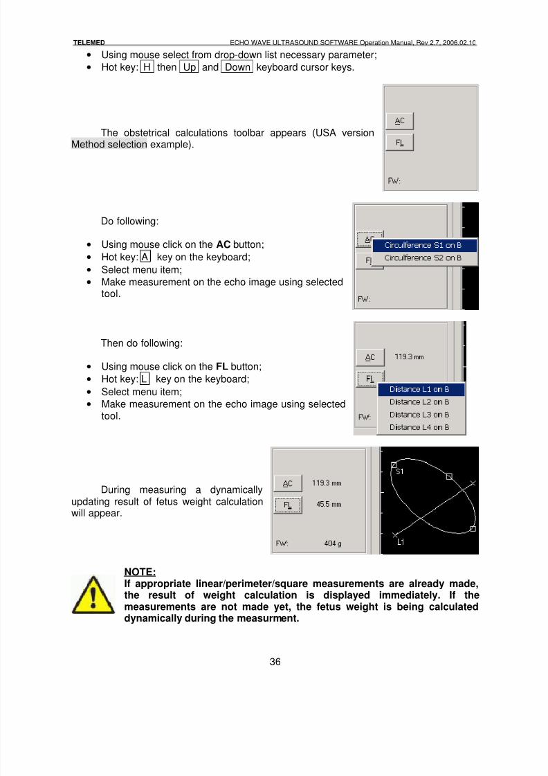
The obstetrical calculations toolbar appears (USA versionMethod selection example).
Do following:
• Using mouse click on the AC button;
• Hot key: A key on the keyboard;
•Select menu item;
• Make measurement on the echo image using selectedtool.
Then do following:
• Using mouse click on the FL button;
• Hot key: L key on the keyboard;
• Select menu item;
•
Make measurement on the echo image using selectedtool.
During measuring a dynamicallyupdating result of fetus weight calculationwill appear.
NOTE:If appropriate linear/perimeter/square measurements are already made,the result of weight calculation is displayed immediately. If themeasurements are not made yet, the fetus weight is being calculateddynamically during the measurment.
8/6/2019 Echo Wave Manual En
http://slidepdf.com/reader/full/echo-wave-manual-en 37/70
TELEMED ECHO WAVE ULTRASOUND SOFTWARE Operation Manual, Rev 2.7, 2006.02.10
37
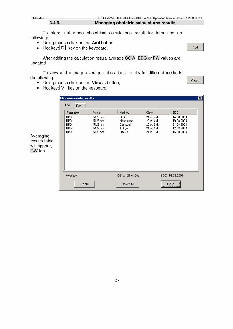
3.4.9. Managing obstetric calculations results
To store just made obstetrical calculations result for later use dofollowing:
• Using mouse click on the Add button;
• Hot key: D key on the keyboard.
After adding the calculation result, average CGW, EDC or FW values areupdated.
To view and manage average calculations results for different methodsdo following:
• Using mouse click on the View… button;
• Hot key: V key on the keyboard.
Averagingresults tablewill appear,GW tab.
8/6/2019 Echo Wave Manual En
http://slidepdf.com/reader/full/echo-wave-manual-en 38/70
TELEMED ECHO WAVE ULTRASOUND SOFTWARE Operation Manual, Rev 2.7, 2006.02.10
38
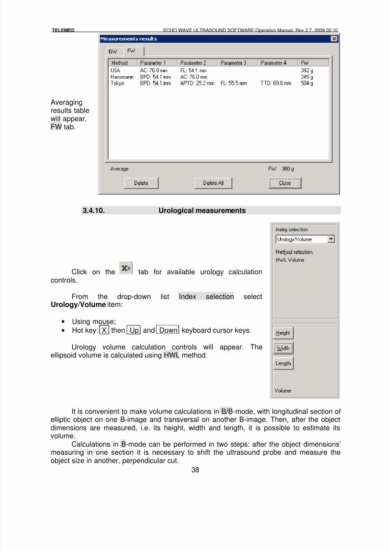
Averagingresults tablewill appear,FW tab.
3.4.10. Urological measurements
Click on the tab for available urology calculationcontrols.
From the drop-down list Index selection selectUrology/Volume item:
• Using mouse;
• Hot key: X then Up and Down keyboard cursor keys.
Urology volume calculation controls will appear. Theellipsoid volume is calculated using HWL method.
It is convenient to make volume calculations in B/B-mode, with longitudinal section ofelliptic object on one B-image and transversal on another B-image. Then, after the objectdimensions are measured, i.e. its height, width and length, it is possible to estimate itsvolume.
Calculations in B-mode can be performed in two steps: after the object dimensions’measuring in one section it is necessary to shift the ultrasound probe and measure theobject size in another, perpendicular cut.
8/6/2019 Echo Wave Manual En
http://slidepdf.com/reader/full/echo-wave-manual-en 39/70
TELEMED ECHO WAVE ULTRASOUND SOFTWARE Operation Manual, Rev 2.7, 2006.02.10
39
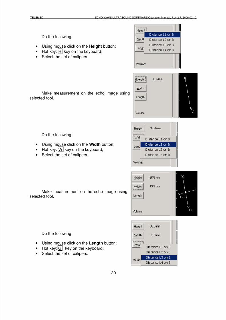
Do the following:
• Using mouse click on the Height button;
• Hot key: H key on the keyboard;
• Select the set of calipers.
Make measurement on the echo image usingselected tool.
Do the following:
• Using mouse click on the Width button;
• Hot key: W key on the keyboard;
• Select the set of calipers.
Make measurement on the echo image usingselected tool.
Do the following:
• Using mouse click on the Length button;
• Hot key: G key on the keyboard;
• Select the set of calipers.
8/6/2019 Echo Wave Manual En
http://slidepdf.com/reader/full/echo-wave-manual-en 40/70
TELEMED ECHO WAVE ULTRASOUND SOFTWARE Operation Manual, Rev 2.7, 2006.02.10
40
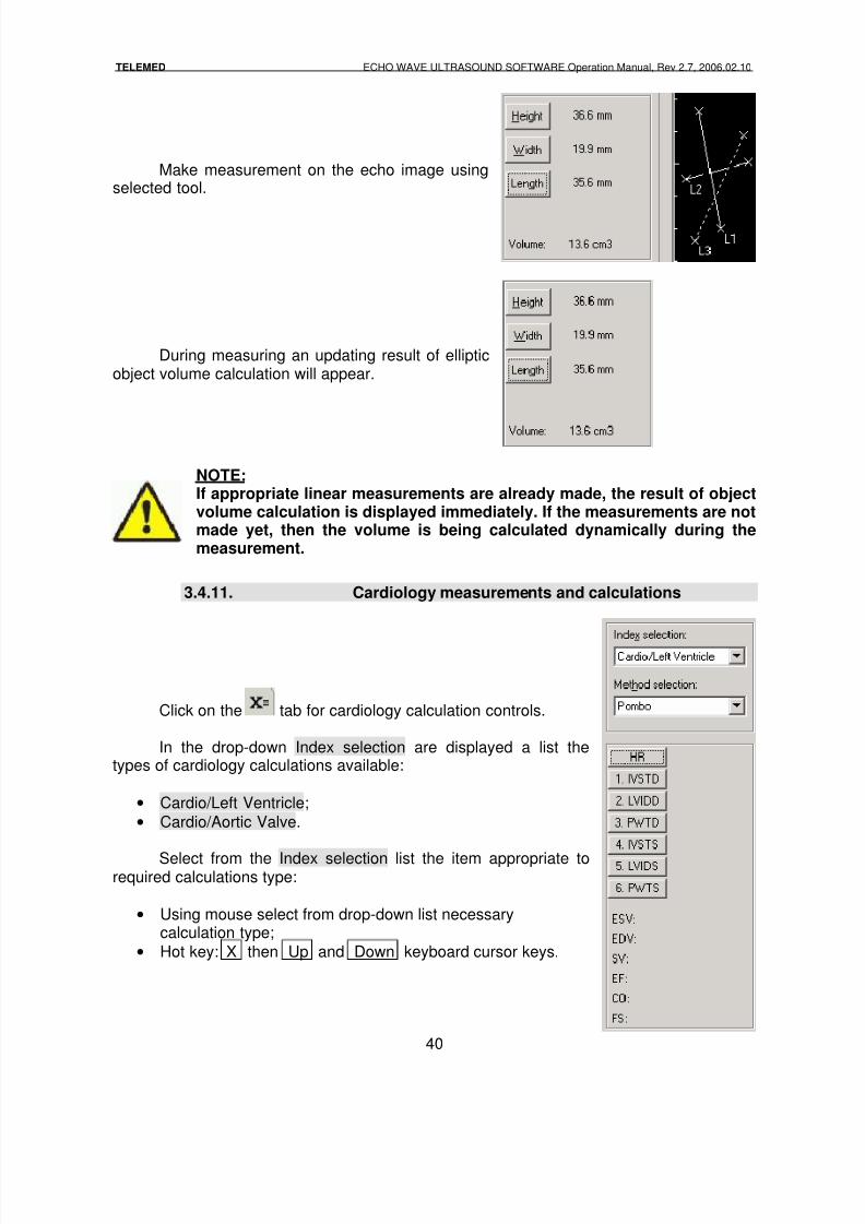
Make measurement on the echo image usingselected tool.
During measuring an updating result of ellipticobject volume calculation will appear.
NOTE:If appropriate linear measurements are already made, the result of objectvolume calculation is displayed immediately. If the measurements are notmade yet, then the volume is being calculated dynamically during themeasurement.
3.4.11. Cardiology measurements and calculations
Click on the tab for cardiology calculation controls.
In the drop-down Index selection are displayed a list thetypes of cardiology calculations available:
• Cardio/Left Ventricle;
• Cardio/Aortic Valve.
Select from the Index selection list the item appropriate torequired calculations type:
• Using mouse select from drop-down list necessarycalculation type;
• Hot key: X then Up and Down keyboard cursor keys.
8/6/2019 Echo Wave Manual En
http://slidepdf.com/reader/full/echo-wave-manual-en 41/70
TELEMED ECHO WAVE ULTRASOUND SOFTWARE Operation Manual, Rev 2.7, 2006.02.10
41
Left Ventricle (B/M or M-mode) measurements and calculations
Left ventricle measurements and calculations can be performed in B/M or M modes.
Select the item Cardio/Left Ventricle in the drop-down listIndex selection.
The volume calculations can be done by one of the mainmethods used for similar calculations.
In the drop-down list Method selection select the itemappropriate to a required method:
• Using mouse select from drop-down list necessary parameter;
• Hot key: H then Up and Down keyboard cursor keys.
Following measurements required for calculations should beperformed:
• LVIDD (left ventricle internal diameter - diastolic);
•
LVIDS (left ventricle internal diameter - systolic);• HR (heart rate).
There are other measurements available to perform forevaluation purposes:
• IVSTD (interventricular septum thickness - diastolic);
• IVSTS (interventricular septum thickness - systolic);
• PWTD (posterior wall thickness - diastolic);
• PWTS (posterior wall thickness - systolic).
Following calculations are shown during parametersmeasurement:
• ESV (end-systolic volume);• EDV (end-diastolic volume);
• SV (stroke volume);
• EF (ejection fraction);
• CO (cardiac output);
• FS (fractional shortening).
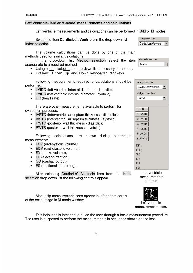
After selecting Cardio/Left Ventricle item from the Indexselection drop-down list the following controls appear.
Left ventriclemeasurements
controls.
Also, help measurement icons appear in left-bottom cornerof the echo image in M-mode window.
Left ventriclemeasurements icon.
This help icon is intended to guide the user through a basic measurement procedure.The user is supposed to perform the measurements in sequence shown on the icon.
8/6/2019 Echo Wave Manual En
http://slidepdf.com/reader/full/echo-wave-manual-en 42/70
TELEMED ECHO WAVE ULTRASOUND SOFTWARE Operation Manual, Rev 2.7, 2006.02.10
42
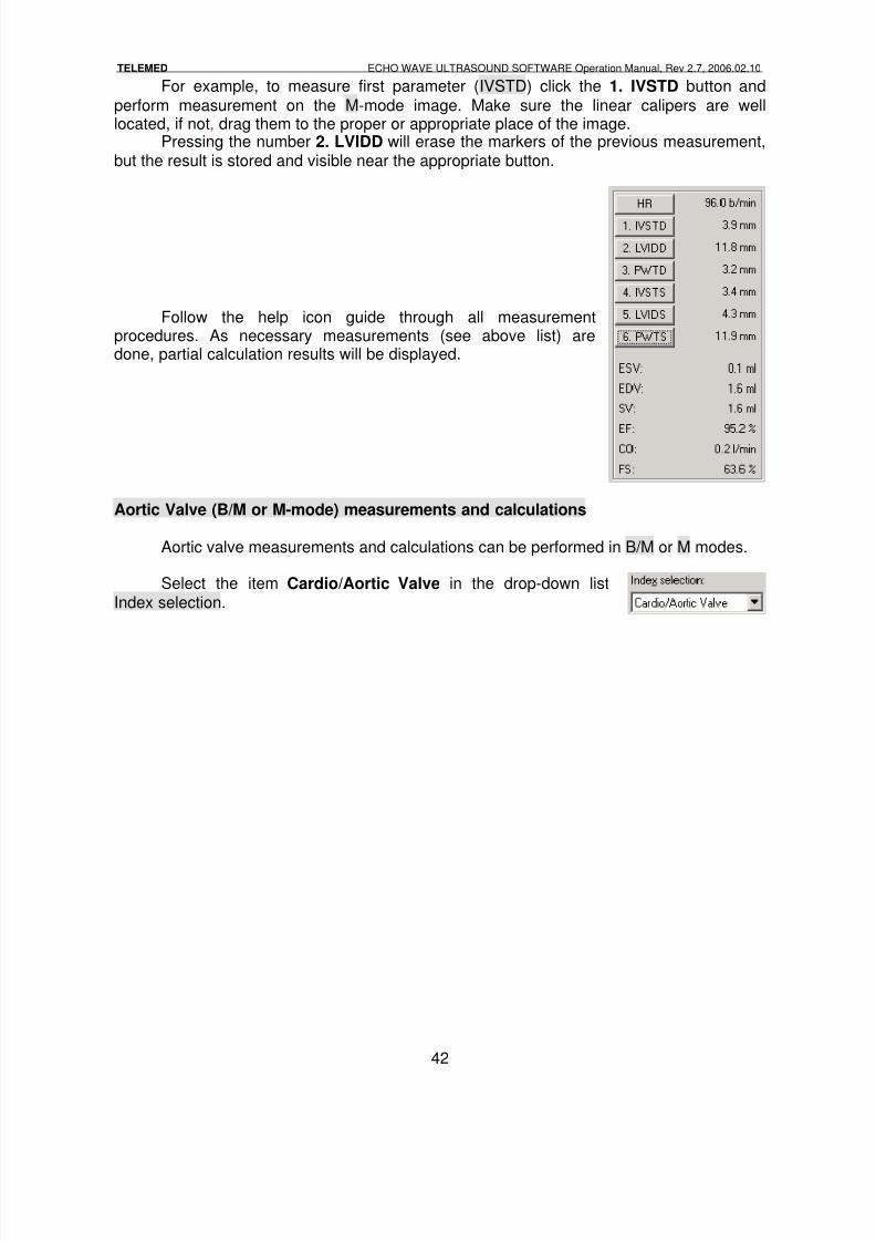
For example, to measure first parameter (IVSTD) click the 1. IVSTD button and
perform measurement on the M-mode image. Make sure the linear calipers are welllocated, if not, drag them to the proper or appropriate place of the image.
Pressing the number 2. LVIDD will erase the markers of the previous measurement,but the result is stored and visible near the appropriate button.
Follow the help icon guide through all measurementprocedures. As necessary measurements (see above list) aredone, partial calculation results will be displayed.
Aortic Valve (B/M or M-mode) measurements and calculations
Aortic valve measurements and calculations can be performed in B/M or M modes.
Select the item Cardio/Aortic Valve in the drop-down listIndex selection.
8/6/2019 Echo Wave Manual En
http://slidepdf.com/reader/full/echo-wave-manual-en 43/70
TELEMED ECHO WAVE ULTRASOUND SOFTWARE Operation Manual, Rev 2.7, 2006.02.10
43
Following measurements required for calculations should beperformed:
• AOD (aortic diameter),
• LAD (left atrial dimension).
Following calculation is shown during parametersmeasurement:
• LA/AO ratio.
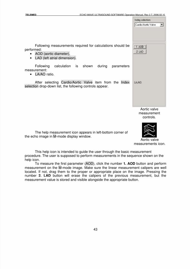
After selecting Cardio/Aortic Valve item from the Indexselection drop-down list, the following controls appear.
Aortic valvemeasurement
controls.
The help measurement icon appears in left-bottom corner ofthe echo image in M-mode display window.
Aortic valvemeasurements icon.
This help icon is intended to guide the user through the basic measurementprocedure. The user is supposed to perform measurements in the sequence shown on thehelp icon.
To measure the first parameter (AOD), click the number 1. AOD button and performmeasurement on the M-mode image. Make sure the linear measurement calipers are welllocated. If not, drag them to the proper or appropriate place on the image. Pressing thenumber 2. LAD button will erase the calipers of the previous measurement, but themeasurement value is stored and visible alongside the appropriate button.
8/6/2019 Echo Wave Manual En
http://slidepdf.com/reader/full/echo-wave-manual-en 44/70
TELEMED ECHO WAVE ULTRASOUND SOFTWARE Operation Manual, Rev 2.7, 2006.02.10
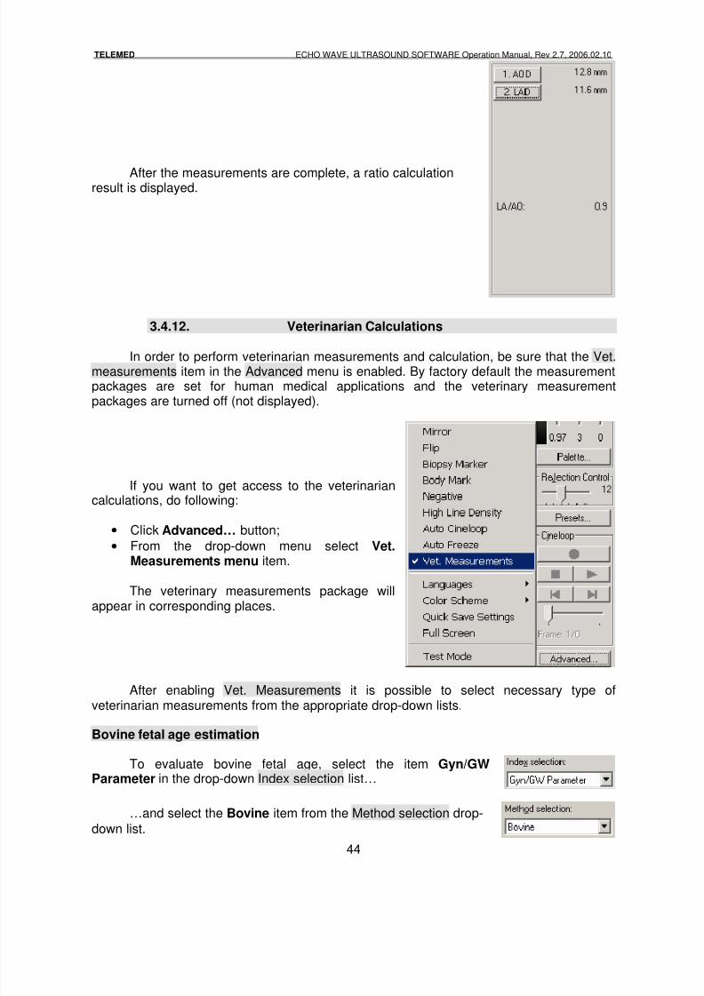
44
After the measurements are complete, a ratio calculationresult is displayed.
3.4.12. Veterinarian Calculations
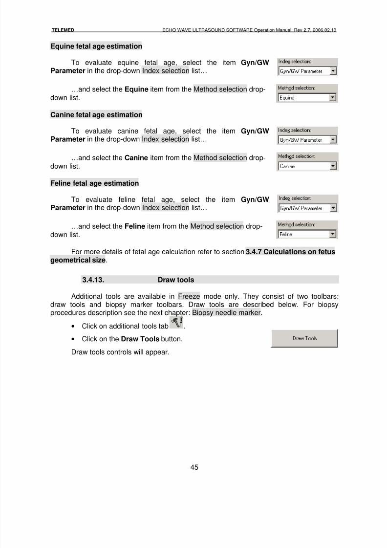
In order to perform veterinarian measurements and calculation, be sure that the Vet.measurements item in the Advanced menu is enabled. By factory default the measurementpackages are set for human medical applications and the veterinary measurementpackages are turned off (not displayed).
If you want to get access to the veterinariancalculations, do following:
• Click Advanced… button;
• From the drop-down menu select Vet.Measurements menu item.
The veterinary measurements package willappear in corresponding places.
After enabling Vet. Measurements it is possible to select necessary type ofveterinarian measurements from the appropriate drop-down lists.
Bovine fetal age estimation
To evaluate bovine fetal age, select the item Gyn/GWParameter in the drop-down Index selection list…
…and select the Bovine item from the Method selection drop-
down list.
8/6/2019 Echo Wave Manual En
http://slidepdf.com/reader/full/echo-wave-manual-en 45/70
TELEMED ECHO WAVE ULTRASOUND SOFTWARE Operation Manual, Rev 2.7, 2006.02.10
45
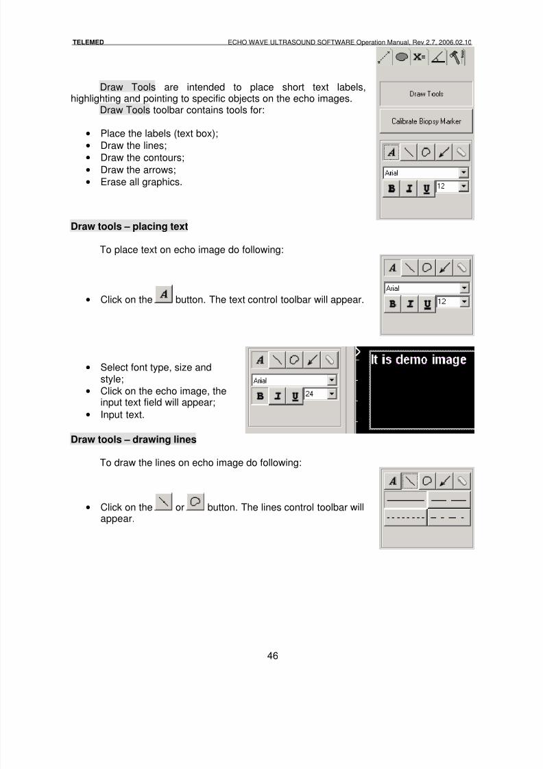
Equine fetal age estimation
To evaluate equine fetal age, select the item Gyn/GWParameter in the drop-down Index selection list…
…and select the Equine item from the Method selection drop-
down list.
Canine fetal age estimation
To evaluate canine fetal age, select the item Gyn/GWParameter in the drop-down Index selection list…
…and select the Canine item from the Method selection drop-down list.
Feline fetal age estimation
To evaluate feline fetal age, select the item Gyn/GWParameter in the drop-down Index selection list…
…and select the Feline item from the Method selection drop-down list.
For more details of fetal age calculation refer to section 3.4.7 Calculations on fetusgeometrical size.
3.4.13. Draw tools
Additional tools are available in Freeze mode only. They consist of two toolbars:draw tools and biopsy marker toolbars. Draw tools are described below. For biopsyprocedures description see the next chapter: Biopsy needle marker.
• Click on additional tools tab .
• Click on the Draw Tools button.
Draw tools controls will appear.
8/6/2019 Echo Wave Manual En
http://slidepdf.com/reader/full/echo-wave-manual-en 46/70
TELEMED ECHO WAVE ULTRASOUND SOFTWARE Operation Manual, Rev 2.7, 2006.02.10
46
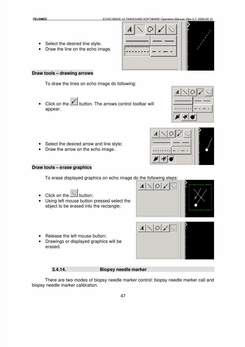
Draw Tools are intended to place short text labels,highlighting and pointing to specific objects on the echo images.
Draw Tools toolbar contains tools for:
• Place the labels (text box);• Draw the lines;
• Draw the contours;
• Draw the arrows;
• Erase all graphics.
Draw tools – placing text
To place text on echo image do following:
• Click on the button. The text control toolbar will appear.
• Select font type, size andstyle;
• Click on the echo image, the
input text field will appear;• Input text.
Draw tools – drawing lines
To draw the lines on echo image do following:
• Click on the or button. The lines control toolbar willappear.
8/6/2019 Echo Wave Manual En
http://slidepdf.com/reader/full/echo-wave-manual-en 47/70
TELEMED ECHO WAVE ULTRASOUND SOFTWARE Operation Manual, Rev 2.7, 2006.02.10
47
• Select the desired line style;
• Draw the line on the echo image.
Draw tools – drawing arrows
To draw the lines on echo image do following:
• Click on the button. The arrows control toolbar willappear.
• Select the desired arrow and line style;
• Draw the arrow on the echo image.
Draw tools – erase graphics
To erase displayed graphics on echo image do the following steps:
• Click on the button;
• Using left mouse button pressed select theobject to be erased into the rectangle;
• Release the left mouse button;
•
Drawings or displayed graphics will beerased.
3.4.14. Biopsy needle marker
There are two modes of biopsy needle marker control: biopsy needle marker call andbiopsy needle marker calibration.
8/6/2019 Echo Wave Manual En
http://slidepdf.com/reader/full/echo-wave-manual-en 48/70
TELEMED ECHO WAVE ULTRASOUND SOFTWARE Operation Manual, Rev 2.7, 2006.02.10
48
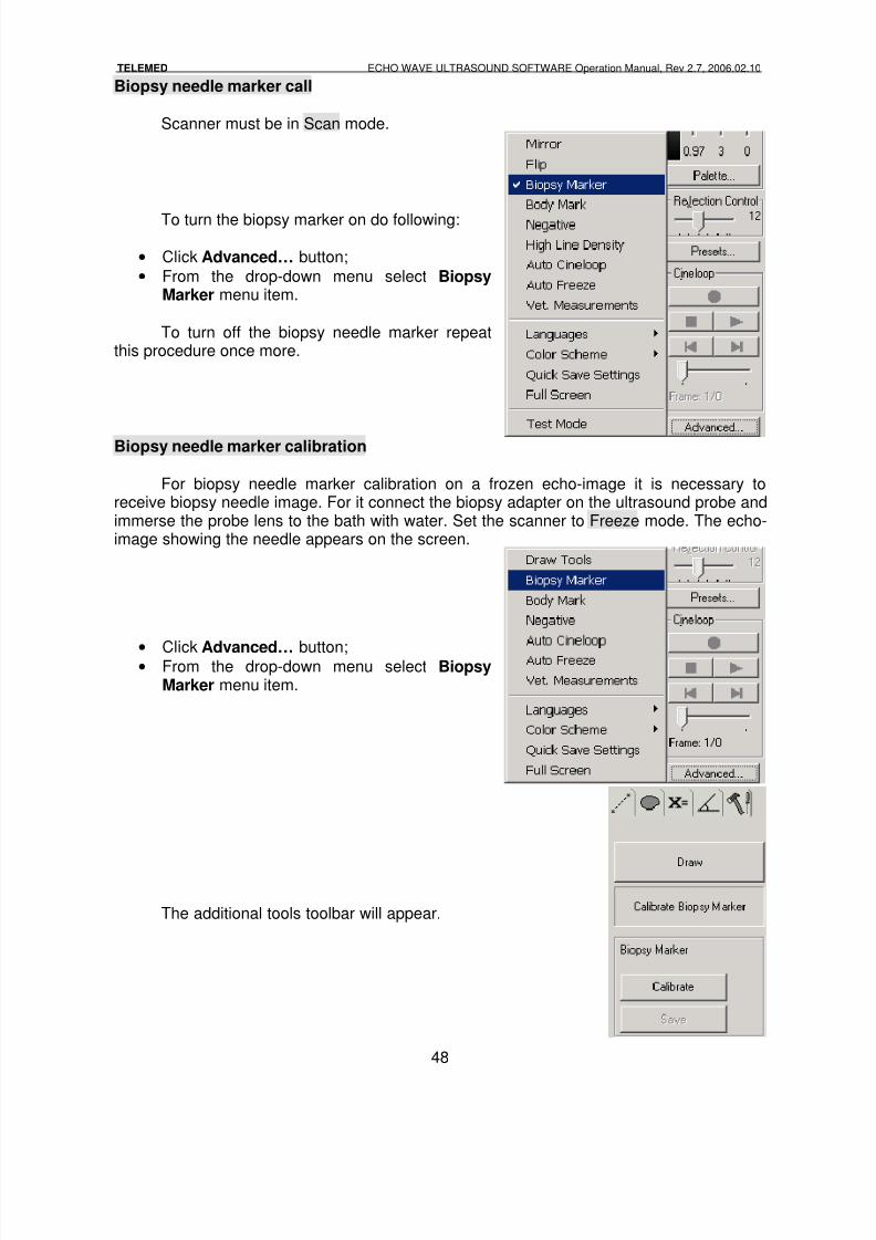
Biopsy needle marker call
Scanner must be in Scan mode.
To turn the biopsy marker on do following:
• Click Advanced… button;
• From the drop-down menu select BiopsyMarker menu item.
To turn off the biopsy needle marker repeatthis procedure once more.
Biopsy needle marker calibration
For biopsy needle marker calibration on a frozen echo-image it is necessary toreceive biopsy needle image. For it connect the biopsy adapter on the ultrasound probe andimmerse the probe lens to the bath with water. Set the scanner to Freeze mode. The echo-image showing the needle appears on the screen.
•
Click Advanced… button;• From the drop-down menu select Biopsy
Marker menu item.
The additional tools toolbar will appear.
8/6/2019 Echo Wave Manual En
http://slidepdf.com/reader/full/echo-wave-manual-en 49/70
TELEMED ECHO WAVE ULTRASOUND SOFTWARE Operation Manual, Rev 2.7, 2006.02.10
49
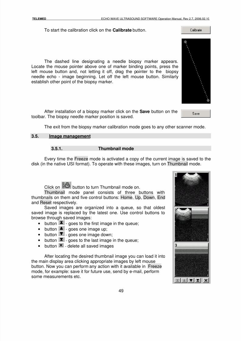
To start the calibration click on the Calibrate button.
The dashed line designating a needle biopsy marker appears.Locate the mouse pointer above one of marker binding points, press theleft mouse button and, not letting it off, drag the pointer to the biopsyneedle echo - image beginning. Let off the left mouse button. Similarlyestablish other point of the biopsy marker.
After installation of a biopsy marker click on the Save button on thetoolbar. The biopsy needle marker position is saved.
The exit from the biopsy marker calibration mode goes to any other scanner mode.
3.5. Image management
3.5.1. Thumbnail mode
Every time the Freeze mode is activated a copy of the current image is saved to thedisk (in the native USI format). To operate with these images, turn on Thumbnail mode.
Click on button to turn Thumbnail mode on.Thumbnail mode panel consists of three buttons with
thumbnails on them and five control buttons: Home, Up, Down, Endand Reset respectively.
Saved images are organized into a queue, so that oldestsaved image is replaced by the latest one. Use control buttons tobrowse through saved images:
• button - goes to the first image in the queue;
• button - goes one image up;
• button - goes one image down;
• button - goes to the last image in the queue;• button - delete all saved images
After locating the desired thumbnail image you can load it intothe main display area clicking appropriate images by left mousebutton. Now you can perform any action with it available in Freezemode, for example: save it for future use, send by e-mail, performsome measurements etc.
8/6/2019 Echo Wave Manual En
http://slidepdf.com/reader/full/echo-wave-manual-en 50/70
TELEMED ECHO WAVE ULTRASOUND SOFTWARE Operation Manual, Rev 2.7, 2006.02.10
50
NOTES:The number of available images – 16. When the thumbnail queue gets full,the oldest image in it will be replaced by the current one each time“freezing” the image.After exiting from the application all the images from the queue will beerased. So, if you need to save some of the images from the queue for
later use, do it immediately.
3.5.2. Saving to file
Saving the ultrasound data to file is possible only in Freeze mode. The scanner haspossibility to save files in such formats:
• Echo-image in BMP (Windows bitmap) format;
• Echo Image in USI (Ultrasound Image) format;
• Report Image in BMP (Windows bitmap) format;
• Recorded to memory Cineloop data in AVI compressed format;
• Recorded to memory Cineloop data in AVI un-compressed format
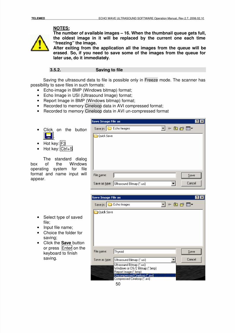
• Click on the button
;
• Hot key: F3
• Hot key: Ctrl+S
The standard dialogbox of the Windowsoperating system for file
format and name input willappear.
• Select type of savedfile;
• Input file name;
• Choice the folder forsaving;
• Click the Save button
or press Enter on thekeyboard to finishsaving.
8/6/2019 Echo Wave Manual En
http://slidepdf.com/reader/full/echo-wave-manual-en 51/70
TELEMED ECHO WAVE ULTRASOUND SOFTWARE Operation Manual, Rev 2.7, 2006.02.10
51
NOTES:The echo-image in BMP format can be opened by third party applicationssuch as: graphic editors, image browsers and etc.The file in USI format contains all comments of inspection, measurementresults, patient information and etc. After opening this file systemrestores all working environment before saving process.
Report Image in BMP format contains same information as printing toprinter: patient information, measurements results, comments to image.Compressed Cineloop format dramatically (as usual, by 20-30 times)reduce file size. We are recommending using compressed Cineloop fileformat for sending via e-mail, to save on floppy disk. But this format islossy compression.The Cineloop video file in un-compressed format has maximum imagequality, but file size is too big for e-mail.
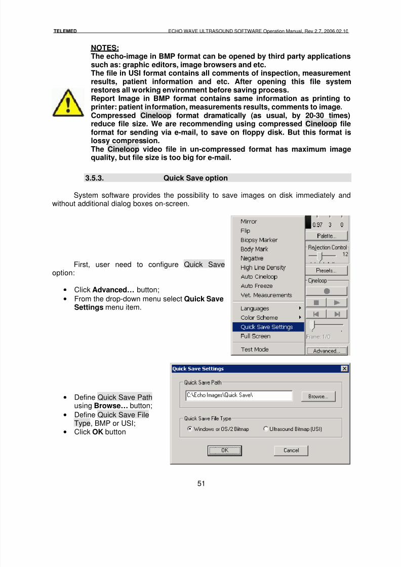
3.5.3. Quick Save option
System software provides the possibility to save images on disk immediately andwithout additional dialog boxes on-screen.
First, user need to configure Quick Saveoption:
• Click Advanced… button;
• From the drop-down menu select Quick SaveSettings menu item.
• Define Quick Save Pathusing Browse… button;
• Define Quick Save FileType, BMP or USI;
• Click OK button
8/6/2019 Echo Wave Manual En
http://slidepdf.com/reader/full/echo-wave-manual-en 52/70
TELEMED ECHO WAVE ULTRASOUND SOFTWARE Operation Manual, Rev 2.7, 2006.02.10
52
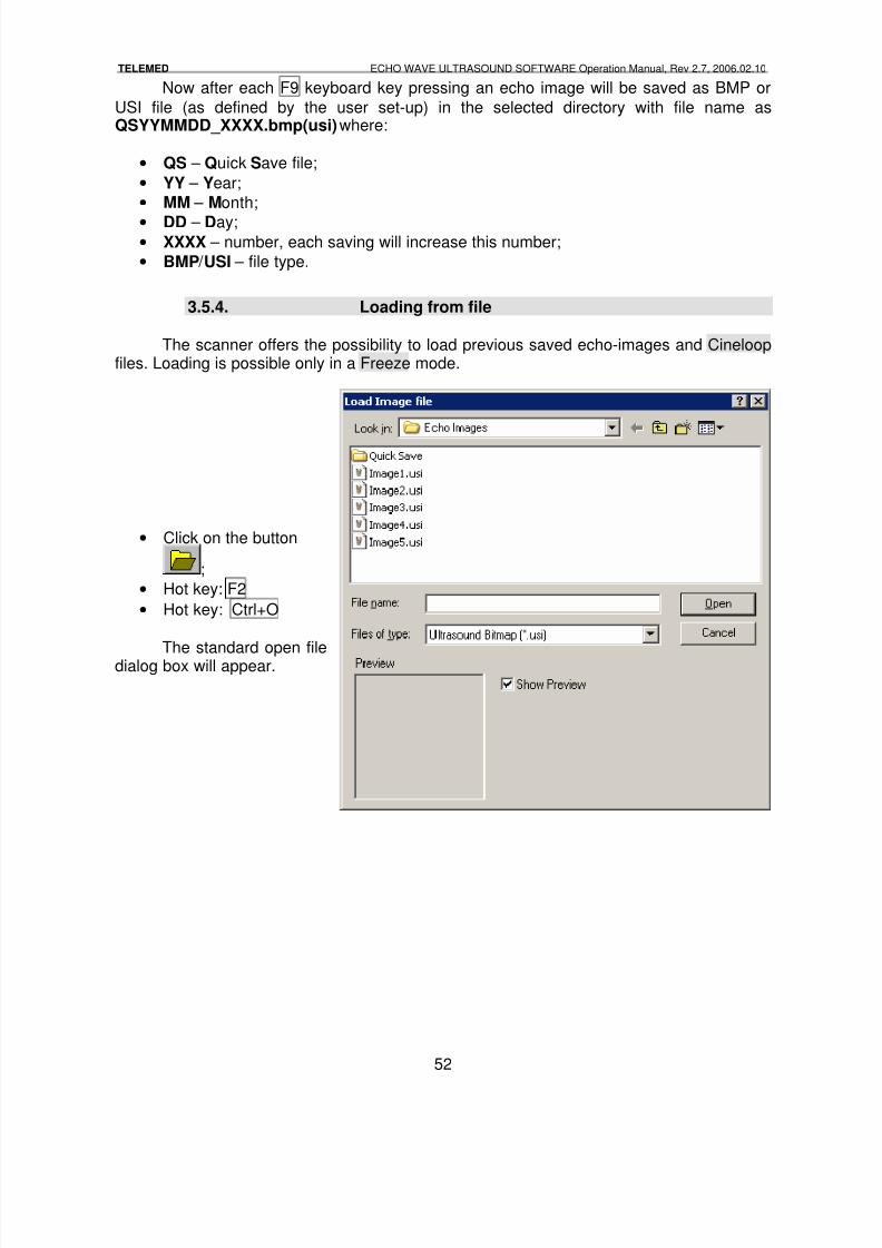
Now after each F9 keyboard key pressing an echo image will be saved as BMP or
USI file (as defined by the user set-up) in the selected directory with file name asQSYYMMDD_XXXX.bmp(usi) where:
• QS – Quick Save file;
• YY – Year;
• MM – Month;
• DD – Day;• XXXX – number, each saving will increase this number;
• BMP / USI – file type.
3.5.4. Loading from file
The scanner offers the possibility to load previous saved echo-images and Cineloopfiles. Loading is possible only in a Freeze mode.
• Click on the button
;
• Hot key: F2
• Hot key: Ctrl+O
The standard open filedialog box will appear.
8/6/2019 Echo Wave Manual En
http://slidepdf.com/reader/full/echo-wave-manual-en 53/70
TELEMED ECHO WAVE ULTRASOUND SOFTWARE Operation Manual, Rev 2.7, 2006.02.10
53
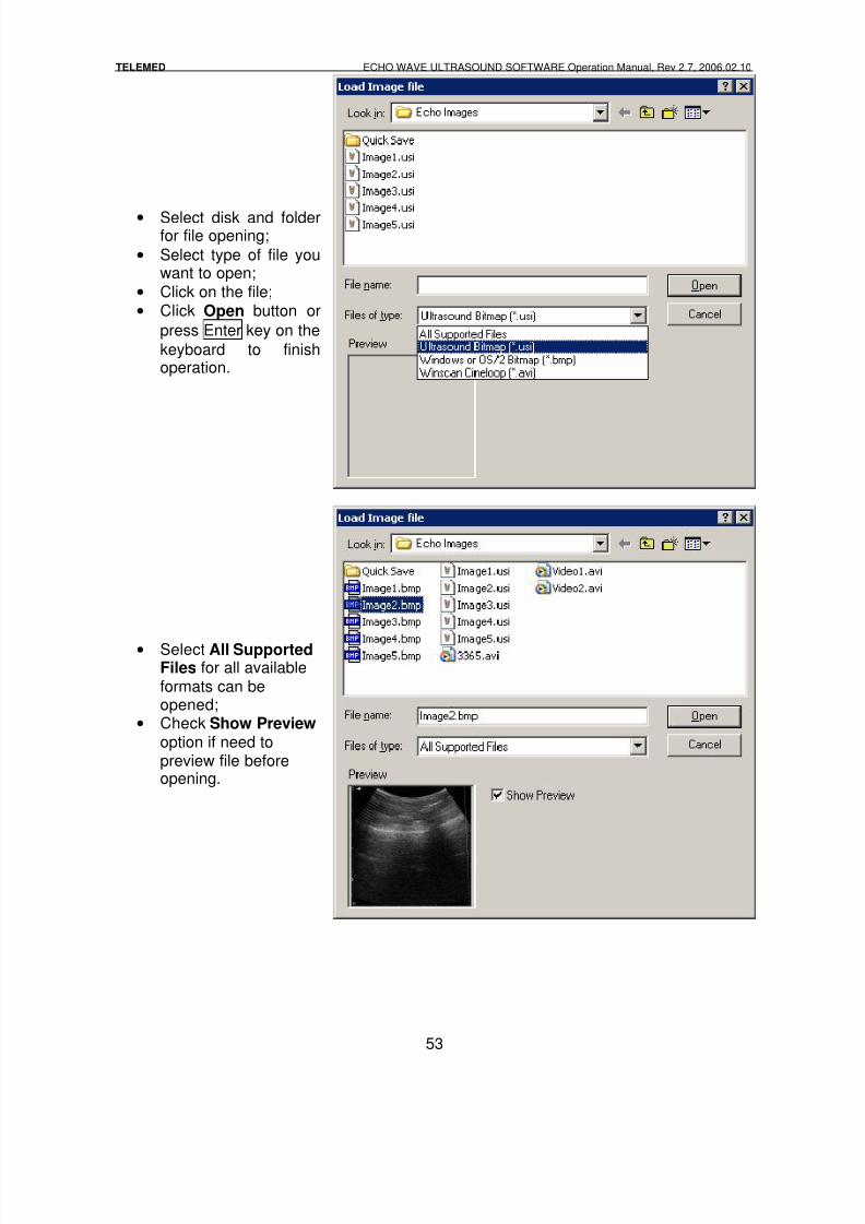
• Select disk and folderfor file opening;
• Select type of file youwant to open;
• Click on the file;
• Click Open button or
press Enter key on the
keyboard to finishoperation.
• Select All SupportedFiles for all availableformats can beopened;
• Check Show Preview option if need topreview file beforeopening.
8/6/2019 Echo Wave Manual En
http://slidepdf.com/reader/full/echo-wave-manual-en 54/70
TELEMED ECHO WAVE ULTRASOUND SOFTWARE Operation Manual, Rev 2.7, 2006.02.10
54
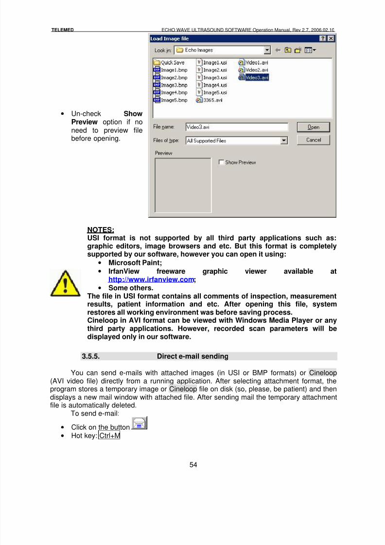
• Un-check ShowPreview option if noneed to preview filebefore opening.
NOTES:USI format is not supported by all third party applications such as:graphic editors, image browsers and etc. But this format is completelysupported by our software, however you can open it using:
• Microsoft Paint;• IrfanView freeware graphic viewer available at
http://www.irfanview.com;• Some others.
The file in USI format contains all comments of inspection, measurementresults, patient information and etc. After opening this file, systemrestores all working environment was before saving process.Cineloop in AVI format can be viewed with Windows Media Player or anythird party applications. However, recorded scan parameters will bedisplayed only in our software.
3.5.5. Direct e-mail sending
You can send e-mails with attached images (in USI or BMP formats) or Cineloop
(AVI video file) directly from a running application. After selecting attachment format, theprogram stores a temporary image or Cineloop file on disk (so, please, be patient) and thendisplays a new mail window with attached file. After sending mail the temporary attachmentfile is automatically deleted.
To send e-mail:
• Click on the button
• Hot key: Ctrl+M
8/6/2019 Echo Wave Manual En
http://slidepdf.com/reader/full/echo-wave-manual-en 55/70
TELEMED ECHO WAVE ULTRASOUND SOFTWARE Operation Manual, Rev 2.7, 2006.02.10
55
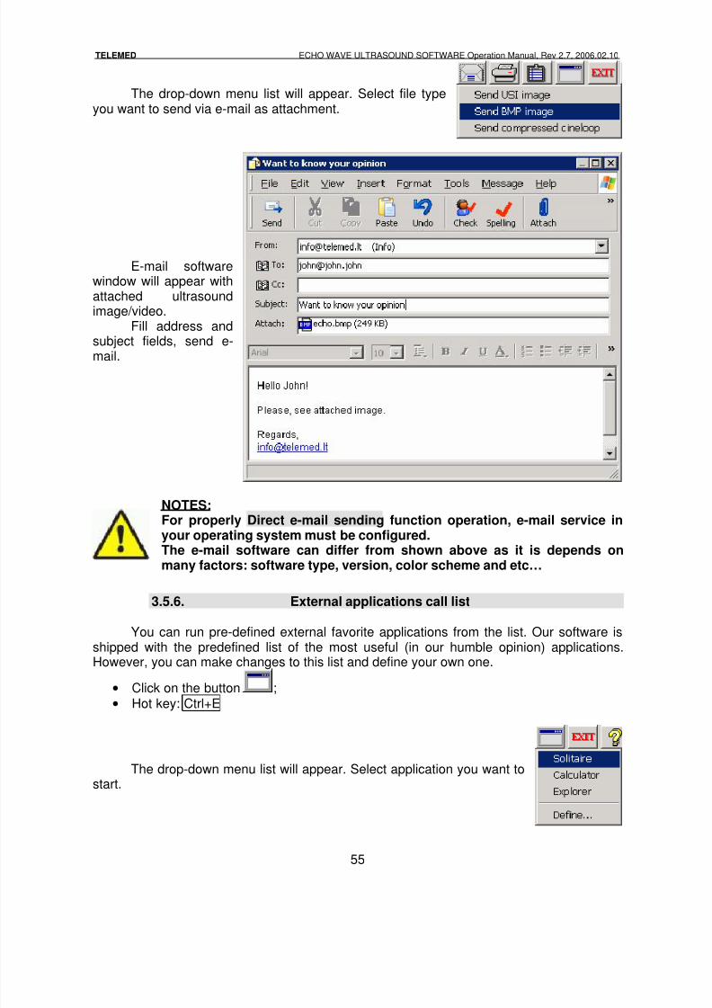
The drop-down menu list will appear. Select file typeyou want to send via e-mail as attachment.
E-mail softwarewindow will appear withattached ultrasoundimage/video.
Fill address andsubject fields, send e-
mail.
NOTES:For properly Direct e-mail sending function operation, e-mail service inyour operating system must be configured.The e-mail software can differ from shown above as it is depends onmany factors: software type, version, color scheme and etc…
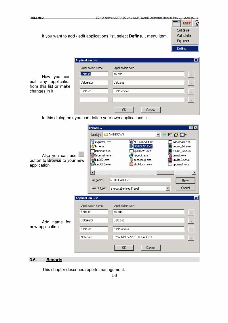
3.5.6. External applications call list
You can run pre-defined external favorite applications from the list. Our software isshipped with the predefined list of the most useful (in our humble opinion) applications.However, you can make changes to this list and define your own one.
• Click on the button ;
•Hot key: Ctrl+E
The drop-down menu list will appear. Select application you want tostart.
8/6/2019 Echo Wave Manual En
http://slidepdf.com/reader/full/echo-wave-manual-en 56/70
8/6/2019 Echo Wave Manual En
http://slidepdf.com/reader/full/echo-wave-manual-en 57/70
TELEMED ECHO WAVE ULTRASOUND SOFTWARE Operation Manual, Rev 2.7, 2006.02.10
57
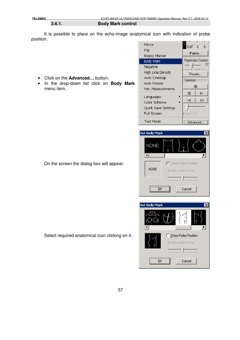
3.6.1. Body Mark control
It is possible to place on the echo-image anatomical icon with indication of probeposition.
• Click on the Advanced… button;
• In the drop-down list click on Body Mark menu item.
On the screen the dialog box will appear.
Select required anatomical icon clicking on it.
8/6/2019 Echo Wave Manual En
http://slidepdf.com/reader/full/echo-wave-manual-en 58/70
TELEMED ECHO WAVE ULTRASOUND SOFTWARE Operation Manual, Rev 2.7, 2006.02.10
58
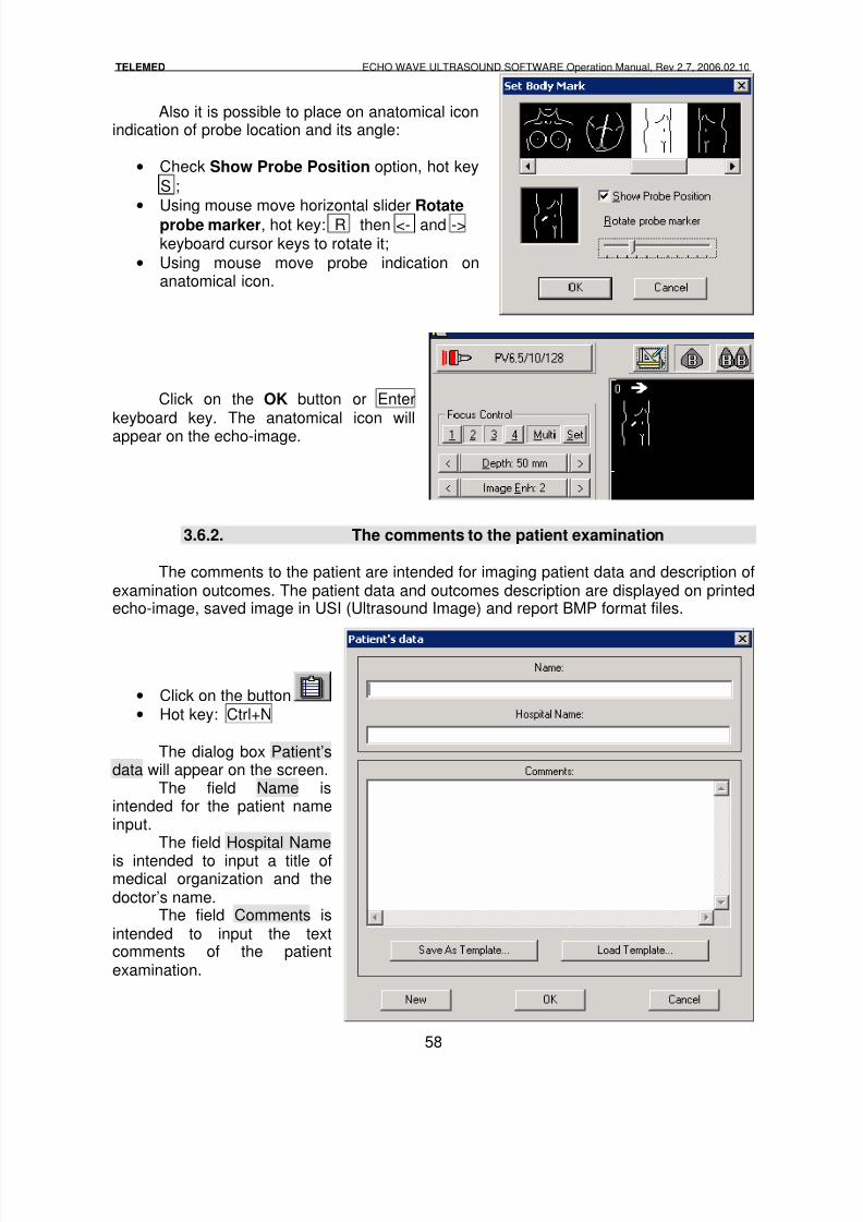
Also it is possible to place on anatomical iconindication of probe location and its angle:
• Check Show Probe Position option, hot key
S ;
•
Using mouse move horizontal slider Rotateprobe marker, hot key: R then <- and ->keyboard cursor keys to rotate it;
• Using mouse move probe indication onanatomical icon.
Click on the OK button or Enterkeyboard key. The anatomical icon willappear on the echo-image.
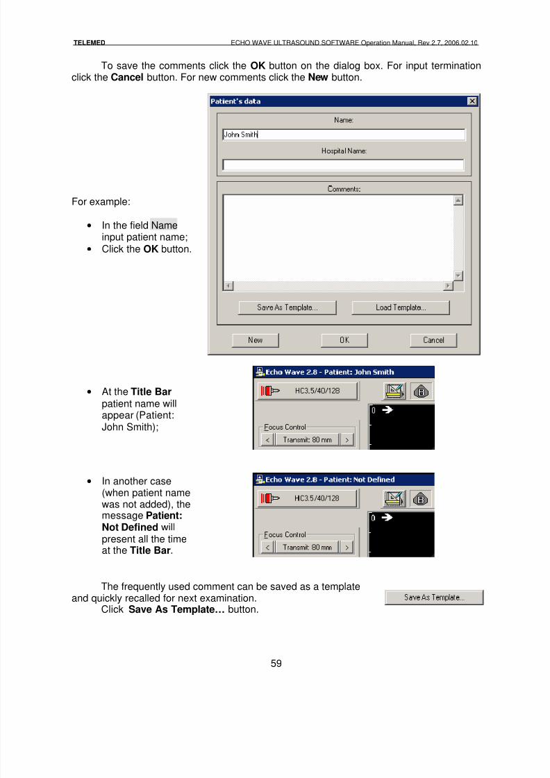
3.6.2. The comments to the patient examination
The comments to the patient are intended for imaging patient data and description ofexamination outcomes. The patient data and outcomes description are displayed on printedecho-image, saved image in USI (Ultrasound Image) and report BMP format files.
• Click on the button• Hot key: Ctrl+N
The dialog box Patient’sdata will appear on the screen.
The field Name isintended for the patient nameinput.
The field Hospital Name
is intended to input a title ofmedical organization and thedoctor’s name.
The field Comments isintended to input the textcomments of the patientexamination.
8/6/2019 Echo Wave Manual En
http://slidepdf.com/reader/full/echo-wave-manual-en 59/70
TELEMED ECHO WAVE ULTRASOUND SOFTWARE Operation Manual, Rev 2.7, 2006.02.10
59
To save the comments click the OK button on the dialog box. For input terminationclick the Cancel button. For new comments click the New button.
For example:
• In the field Nameinput patient name;
• Click the OK button.
• At the Title Bar
patient name willappear (Patient:John Smith);
• In another case(when patient namewas not added), themessage Patient:Not Defined willpresent all the timeat the Title Bar.
The frequently used comment can be saved as a templateand quickly recalled for next examination.
Click Save As Template… button.
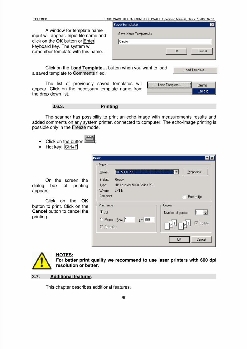
8/6/2019 Echo Wave Manual En
http://slidepdf.com/reader/full/echo-wave-manual-en 60/70
TELEMED ECHO WAVE ULTRASOUND SOFTWARE Operation Manual, Rev 2.7, 2006.02.10
60
A window for template nameinput will appear. Input file name andclick on the OK button or Enterkeyboard key. The system willremember template with this name.
Click on the Load Template… button when you want to loada saved template to Comments filed.
The list of previously saved templates willappear. Click on the necessary template name fromthe drop-down list.
3.6.3. Printing
The scanner has possibility to print an echo-image with measurements results and
added comments on any system printer, connected to computer. The echo-image printing ispossible only in the Freeze mode.
• Click on the button ;
• Hot key: Ctrl+P
On the screen thedialog box of printingappears.
Click on the OK
button to print. Click on theCancel button to cancel the
printing.
NOTES:For better print quality we recommend to use laser printers with 600 dpiresolution or better.
3.7. Additional features
This chapter describes additional features.
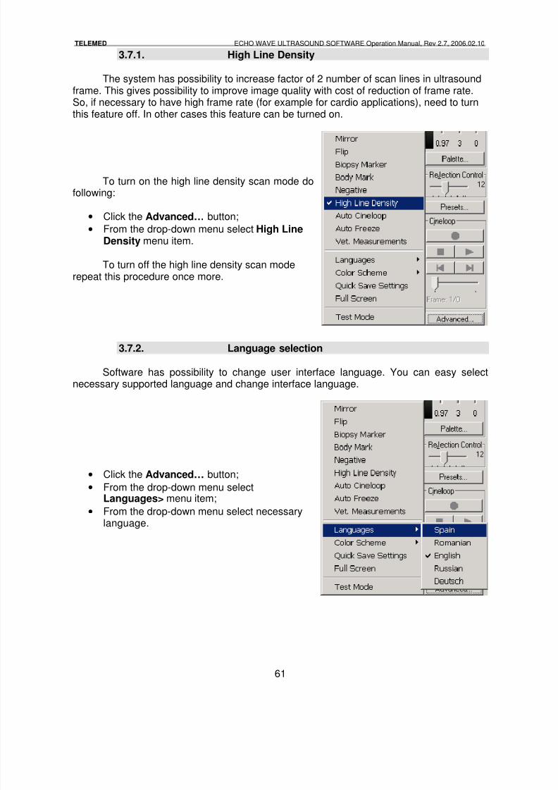
8/6/2019 Echo Wave Manual En
http://slidepdf.com/reader/full/echo-wave-manual-en 61/70
TELEMED ECHO WAVE ULTRASOUND SOFTWARE Operation Manual, Rev 2.7, 2006.02.10
61
3.7.1. High Line Density
The system has possibility to increase factor of 2 number of scan lines in ultrasoundframe. This gives possibility to improve image quality with cost of reduction of frame rate.So, if necessary to have high frame rate (for example for cardio applications), need to turnthis feature off. In other cases this feature can be turned on.
To turn on the high line density scan mode dofollowing:
• Click the Advanced… button;
• From the drop-down menu select High LineDensity menu item.
To turn off the high line density scan mode
repeat this procedure once more.
3.7.2. Language selection
Software has possibility to change user interface language. You can easy selectnecessary supported language and change interface language.
• Click the Advanced… button;
• From the drop-down menu selectLanguages> menu item;
• From the drop-down menu select necessarylanguage.
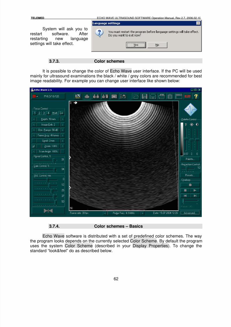
8/6/2019 Echo Wave Manual En
http://slidepdf.com/reader/full/echo-wave-manual-en 62/70
TELEMED ECHO WAVE ULTRASOUND SOFTWARE Operation Manual, Rev 2.7, 2006.02.10
62
System will ask you torestart software. Afterrestarting new languagesettings will take effect.
3.7.3. Color schemes
It is possible to change the color of Echo Wave user interface. If the PC will be usedmainly for ultrasound examinations the black / white / grey colors are recommended for bestimage readability. For example you can change user interface like shown below:
3.7.4. Color schemes – Basics
Echo Wave software is distributed with a set of predefined color schemes. The waythe program looks depends on the currently selected Color Scheme. By default the programuses the system Color Scheme (described in your Display Properties). To change thestandard “look&feel” do as described below.
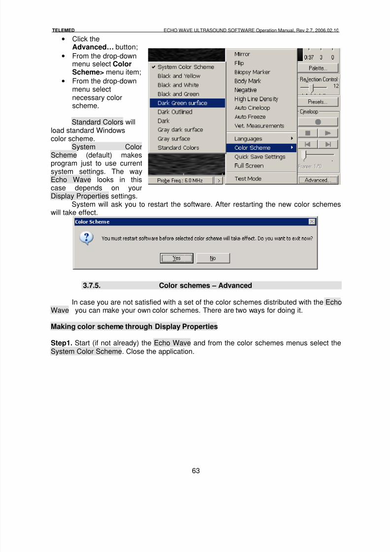
8/6/2019 Echo Wave Manual En
http://slidepdf.com/reader/full/echo-wave-manual-en 63/70
TELEMED ECHO WAVE ULTRASOUND SOFTWARE Operation Manual, Rev 2.7, 2006.02.10
63
• Click theAdvanced… button;
• From the drop-downmenu select ColorScheme> menu item;
• From the drop-downmenu select
necessary colorscheme.
Standard Colors willload standard Windowscolor scheme.
System ColorScheme (default) makesprogram just to use currentsystem settings. The wayEcho Wave looks in thiscase depends on yourDisplay Properties settings.
System will ask you to restart the software. After restarting the new color schemeswill take effect.
3.7.5. Color schemes – Advanced
In case you are not satisfied with a set of the color schemes distributed with the EchoWave you can make your own color schemes. There are two ways for doing it.
Making color scheme through Display Properties
Step1. Start (if not already) the Echo Wave and from the color schemes menus select theSystem Color Scheme. Close the application.
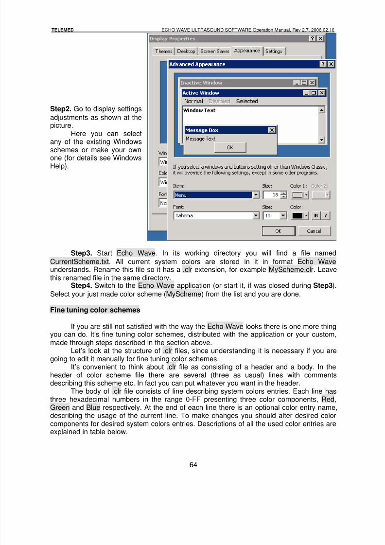
8/6/2019 Echo Wave Manual En
http://slidepdf.com/reader/full/echo-wave-manual-en 64/70
TELEMED ECHO WAVE ULTRASOUND SOFTWARE Operation Manual, Rev 2.7, 2006.02.10
64
Step2. Go to display settings
adjustments as shown at thepicture.
Here you can selectany of the existing Windowsschemes or make your ownone (for details see WindowsHelp).
Step3. Start Echo Wave. In its working directory you will find a file named
CurrentScheme.txt. All current system colors are stored in it in format Echo Waveunderstands. Rename this file so it has a .clr extension, for example MyScheme.clr. Leavethis renamed file in the same directory.
Step4. Switch to the Echo Wave application (or start it, if was closed during Step3).Select your just made color scheme (MyScheme) from the list and you are done.
Fine tuning color schemes
If you are still not satisfied with the way the Echo Wave looks there is one more thingyou can do. It’s fine tuning color schemes, distributed with the application or your custom,made through steps described in the section above.
Let’s look at the structure of .clr files, since understanding it is necessary if you aregoing to edit it manually for fine tuning color schemes.
It’s convenient to think about .clr file as consisting of a header and a body. In theheader of color scheme file there are several (three as usual) lines with comments
describing this scheme etc. In fact you can put whatever you want in the header.The body of .clr file consists of line describing system colors entries. Each line has
three hexadecimal numbers in the range 0-FF presenting three color components, Red,Green and Blue respectively. At the end of each line there is an optional color entry name,describing the usage of the current line. To make changes you should alter desired colorcomponents for desired system colors entries. Descriptions of all the used color entries areexplained in table below.
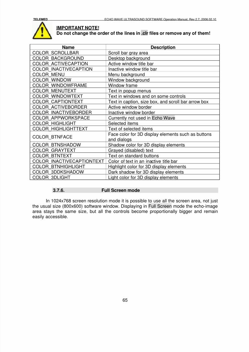
8/6/2019 Echo Wave Manual En
http://slidepdf.com/reader/full/echo-wave-manual-en 65/70
TELEMED ECHO WAVE ULTRASOUND SOFTWARE Operation Manual, Rev 2.7, 2006.02.10
65
IMPORTANT NOTE!Do not change the order of the lines in .clr files or remove any of them!
Name DescriptionCOLOR_SCROLLBAR Scroll bar gray areaCOLOR_BACKGROUND Desktop backgroundCOLOR_ACTIVECAPTION Active window title barCOLOR_INACTIVECAPTION Inactive window title barCOLOR_MENU Menu backgroundCOLOR_WINDOW Window backgroundCOLOR_WINDOWFRAME Window frameCOLOR_MENUTEXT Text in popup menusCOLOR_WINDOWTEXT Text in windows and on some controlsCOLOR_CAPTIONTEXT Text in caption, size box, and scroll bar arrow boxCOLOR_ACTIVEBORDER Active window borderCOLOR_INACTIVEBORDER Inactive window borderCOLOR_APPWORKSPACE Currently not used in Echo Wave
COLOR_HIGHLIGHT Selected itemsCOLOR_HIGHLIGHTTEXT Text of selected items
COLOR_BTNFACEFace color for 3D display elements such as buttonsand dialogs
COLOR_BTNSHADOW Shadow color for 3D display elementsCOLOR_GRAYTEXT Grayed (disabled) textCOLOR_BTNTEXT Text on standard buttons
COLOR_INACTIVECAPTIONTEXT Color of text in an inactive title barCOLOR_BTNHIGHLIGHT Highlight color for 3D display elementsCOLOR_3DDKSHADOW Dark shadow for 3D display elementsCOLOR_3DLIGHT Light color for 3D display elements
3.7.6. Full Screen mode
In 1024x768 screen resolution mode it is possible to use all the screen area, not justthe usual size (800x600) software window. Displaying in Full Screen mode the echo-imagearea stays the same size, but all the controls become proportionally bigger and remaineasily accessible.
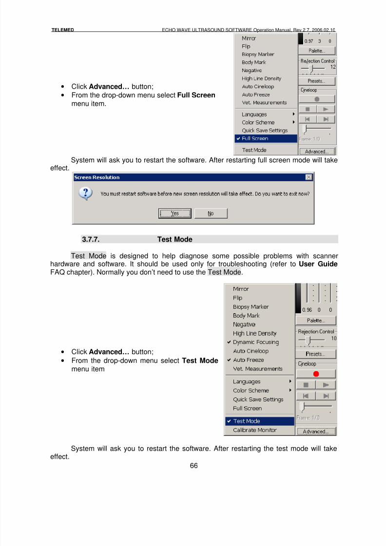
8/6/2019 Echo Wave Manual En
http://slidepdf.com/reader/full/echo-wave-manual-en 66/70
TELEMED ECHO WAVE ULTRASOUND SOFTWARE Operation Manual, Rev 2.7, 2006.02.10
66
• Click Advanced… button;
• From the drop-down menu select Full Screen menu item.
System will ask you to restart the software. After restarting full screen mode will takeeffect.
3.7.7. Test Mode
Test Mode is designed to help diagnose some possible problems with scannerhardware and software. It should be used only for troubleshooting (refer to User Guide FAQ chapter). Normally you don’t need to use the Test Mode.
• Click Advanced… button;
• From the drop-down menu select Test Mode menu item
System will ask you to restart the software. After restarting the test mode will takeeffect.
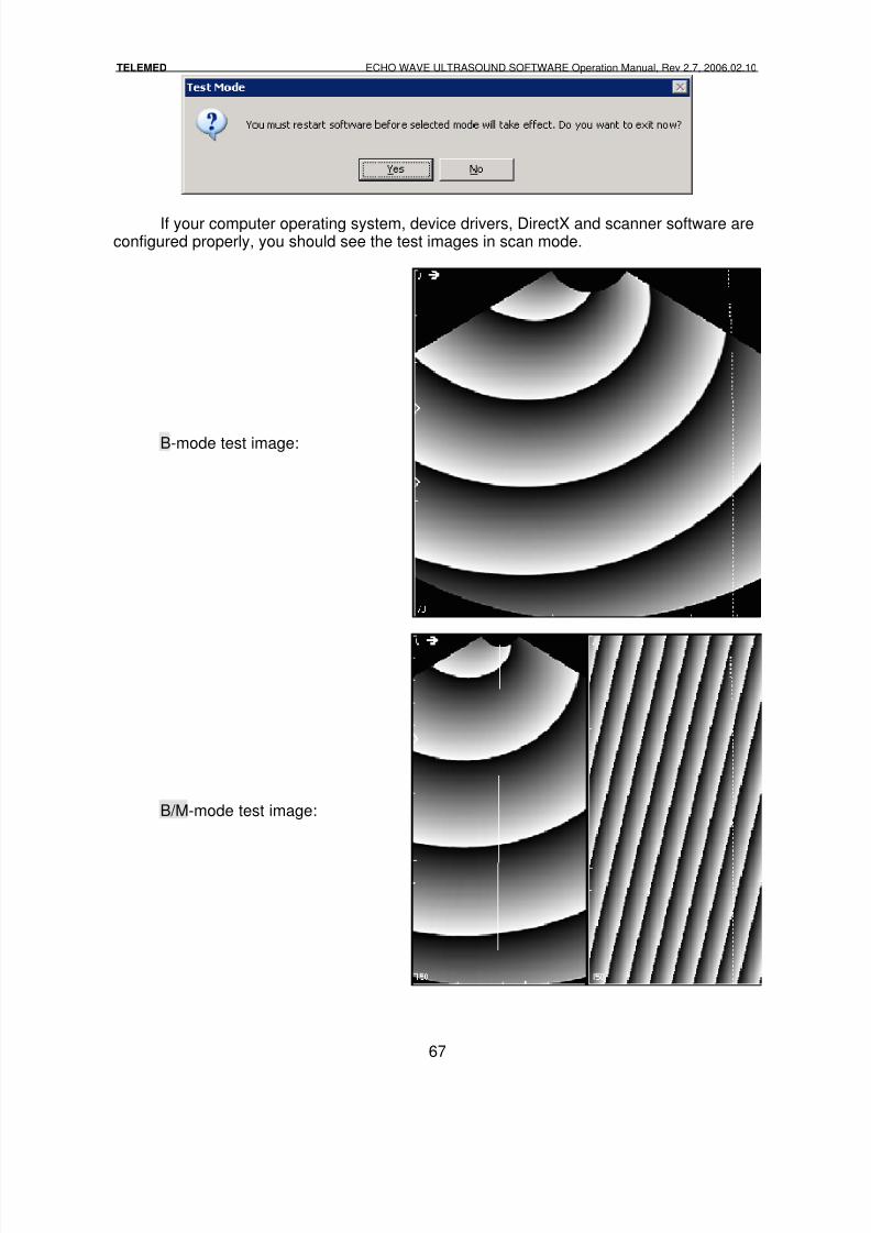
8/6/2019 Echo Wave Manual En
http://slidepdf.com/reader/full/echo-wave-manual-en 67/70
TELEMED ECHO WAVE ULTRASOUND SOFTWARE Operation Manual, Rev 2.7, 2006.02.10
67
If your computer operating system, device drivers, DirectX and scanner software areconfigured properly, you should see the test images in scan mode.
B-mode test image:
B/M-mode test image:
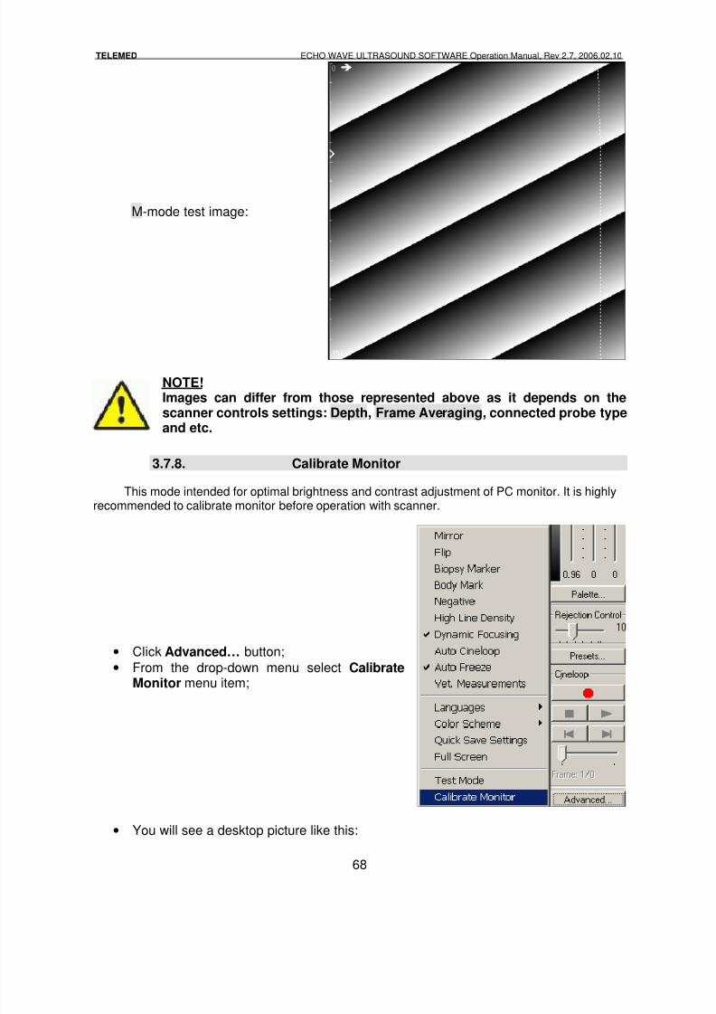
8/6/2019 Echo Wave Manual En
http://slidepdf.com/reader/full/echo-wave-manual-en 68/70
TELEMED ECHO WAVE ULTRASOUND SOFTWARE Operation Manual, Rev 2.7, 2006.02.10
68
M-mode test image:
NOTE!Images can differ from those represented above as it depends on thescanner controls settings: Depth, Frame Averaging, connected probe typeand etc.
3.7.8. Calibrate Monitor
This mode intended for optimal brightness and contrast adjustment of PC monitor. It is highlyrecommended to calibrate monitor before operation with scanner.
• Click Advanced… button;
• From the drop-down menu select CalibrateMonitor menu item;
• You will see a desktop picture like this:
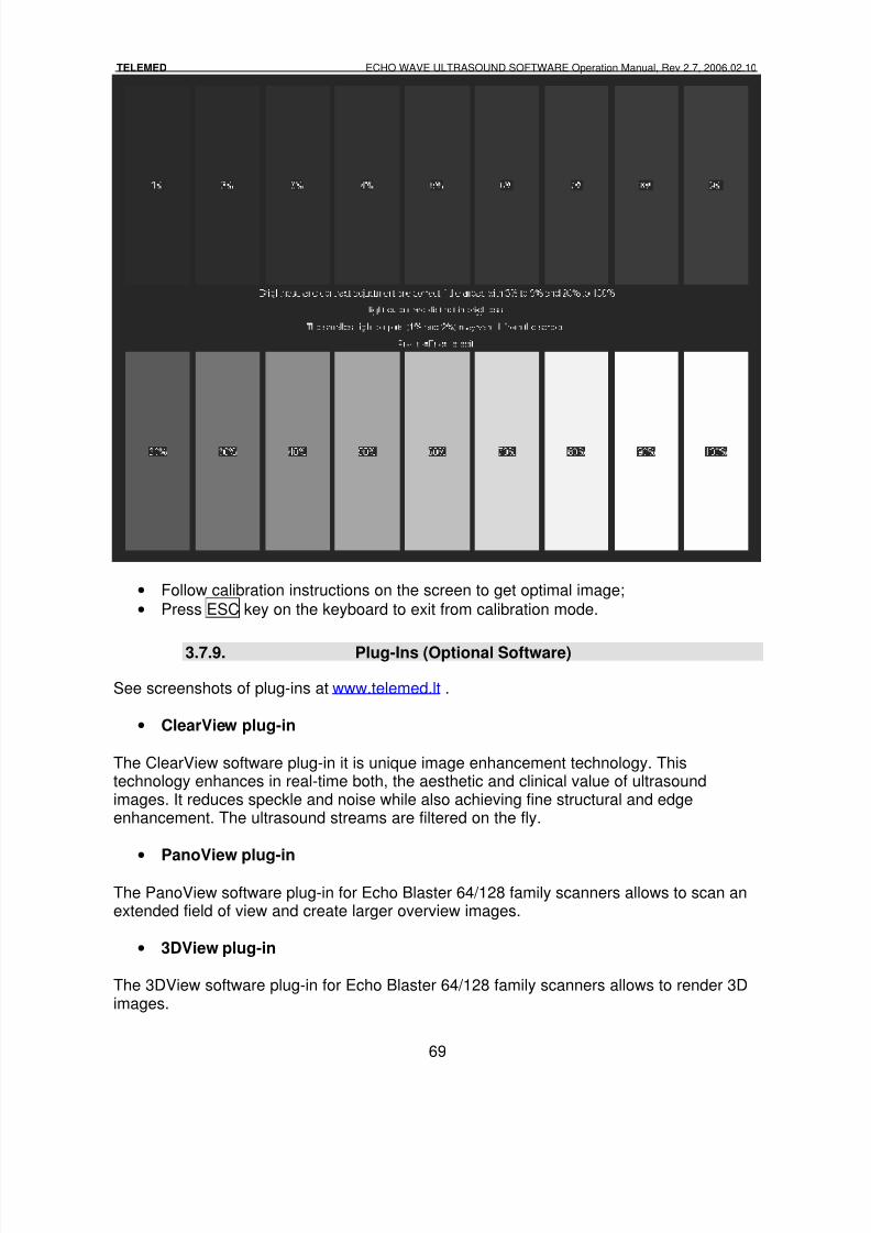
8/6/2019 Echo Wave Manual En
http://slidepdf.com/reader/full/echo-wave-manual-en 69/70
TELEMED ECHO WAVE ULTRASOUND SOFTWARE Operation Manual, Rev 2.7, 2006.02.10
69
• Follow calibration instructions on the screen to get optimal image;
• Press ESC key on the keyboard to exit from calibration mode.
3.7.9. Plug-Ins (Optional Software)
See screenshots of plug-ins at www.telemed.lt .
• ClearView plug-in
The ClearView software plug-in it is unique image enhancement technology. Thistechnology enhances in real-time both, the aesthetic and clinical value of ultrasoundimages. It reduces speckle and noise while also achieving fine structural and edgeenhancement. The ultrasound streams are filtered on the fly.
• PanoView plug-in
The PanoView software plug-in for Echo Blaster 64/128 family scanners allows to scan anextended field of view and create larger overview images.
• 3DView plug-in
The 3DView software plug-in for Echo Blaster 64/128 family scanners allows to render 3Dimages.
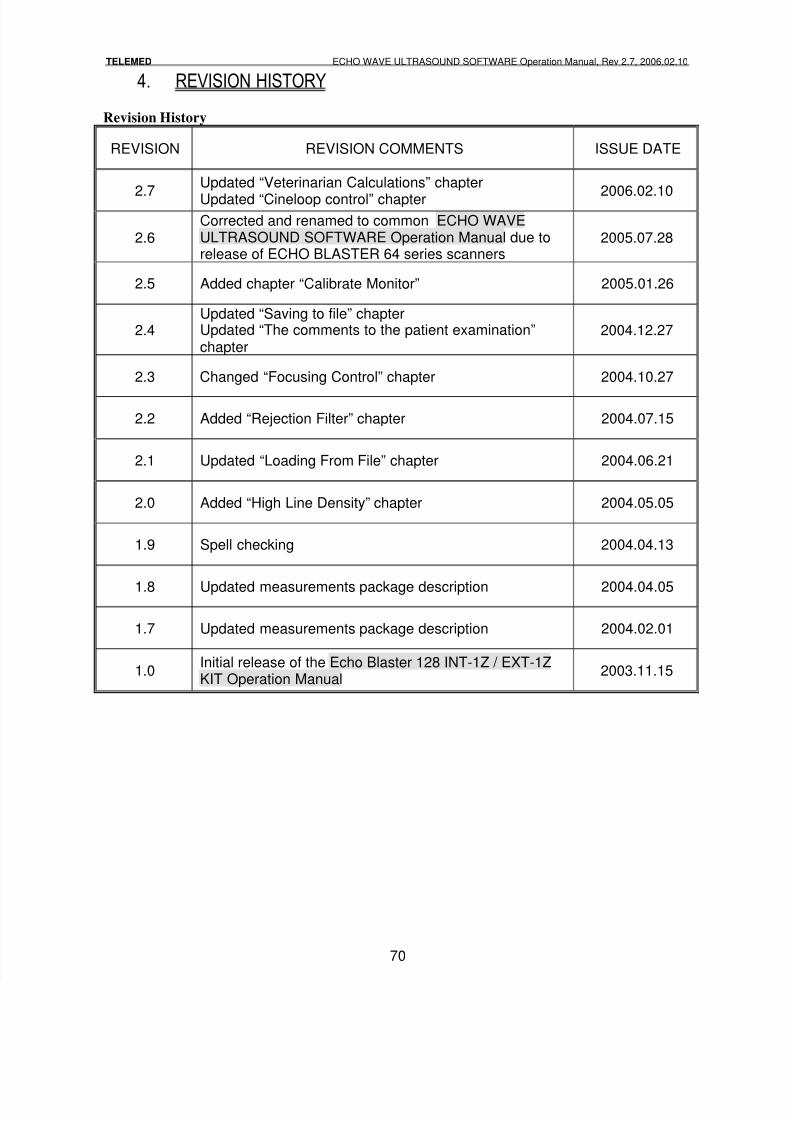
8/6/2019 Echo Wave Manual En
http://slidepdf.com/reader/full/echo-wave-manual-en 70/70
TELEMED ECHO WAVE ULTRASOUND SOFTWARE Operation Manual, Rev 2.7, 2006.02.10
4. REVISION HISTORY
Revision History
REVISION REVISION COMMENTS ISSUE DATE
2.7
Updated “Veterinarian Calculations” chapter
Updated “Cineloop control” chapter 2006.02.10
2.6Corrected and renamed to common ECHO WAVEULTRASOUND SOFTWARE Operation Manual due torelease of ECHO BLASTER 64 series scanners
2005.07.28
2.5 Added chapter “Calibrate Monitor” 2005.01.26
2.4Updated “Saving to file” chapterUpdated “The comments to the patient examination”chapter
2004.12.27
2.3 Changed “Focusing Control” chapter 2004.10.27
2.2 Added “Rejection Filter” chapter 2004.07.15
2.1 Updated “Loading From File” chapter 2004.06.21
2.0 Added “High Line Density” chapter 2004.05.05
1.9 Spell checking 2004.04.13
1.8 Updated measurements package description 2004.04.05
1.7 Updated measurements package description 2004.02.01
1.0Initial release of the Echo Blaster 128 INT-1Z / EXT-1ZKIT Operation Manual
2003.11.15