Embed Size (px)
Citation preview
(NASA-T_-85033) APERTOEE -CYNIBE.ClSIO_ 583-3E_39 :NICI_OWAV£ RADIO_,E£EBS IN SEACE 'NASA) 37 pHC A03/M_ A0| CSCL I_B |,
Uncla_ iG3/q3 g2235
' TechnicalMemorandum 85033
t_ _,___ei,"APERTURE SYNTHESIS FOR
_'_ MICROWAVE RADIOMETERSIN SPACE
D. M. LeVine and J. C. Good..--_
August 1983
NationalAeronauticsandSpaceAdministration
Gerard SpeeeRight CenterGreenbelt,Maryland20771
1983028268
https://ntrs.nasa.gov/search.jsp?R=19830028268 2018-07-15T16:30:24+00:00Z
TM-85033
APERTURE SYNTHESIS FOR
MICROWAVE RADIOMETERS IN SPACE
D. M. Le VineEnvironmental Sensors Branch
Goddard Laboratory for Atmospheric Science
J. C. Good ,Earth Observstory Systems Division
Computer Science Corporation
August 1983
GODDARD SPACE FLIGHT CENTERGreenbelt,Maryland
am
1983028268-002
ABSTRACT
A technique is described for obtaining passive microwave measurements from space for remote
sensing applications with high spatial resolution. The technique invelves measuring the product
of the signal fi'om pairs of antennas at many different antenna spacings, thereby mapping the
correlation function of antenna voltage. The intensity of radiation at the source can be obtained
from the Fourier transform of tim correlation function. Theory will be presented to show how
the technique can be applied to large extended sources such as the earth when observed from space.
As an example, details will be presented for a system with uniformly spaced measurements.
!|
ii
I
1983028268-003

,A"
CONTENTS
Pas_._._e
L INTRODUCTION ................................................... I
IL ANTENNARESPONSEIN THE FREQUENCYDOMAIN .................... 4
III. THETIMEDOMAINANTENNA RESPONSE.............................. 6
IV. SPATIALCORRELATIONFUNCTION .................................. 10
V. SOLUTIONFOR INTENSITYON THE SCENE ............................ 13
VI. AN EXAMPLE...................................................... 16
VII. CONCLUSIONS..................................................... 20
VIII. SUMMARY ........................................................ 23
REFERENCES ...................................................... 24
APPENDIX .............. .......................................... 25
• iz
i
l
i
. ill
1983028268-004
p
ILLUSTRATIONS
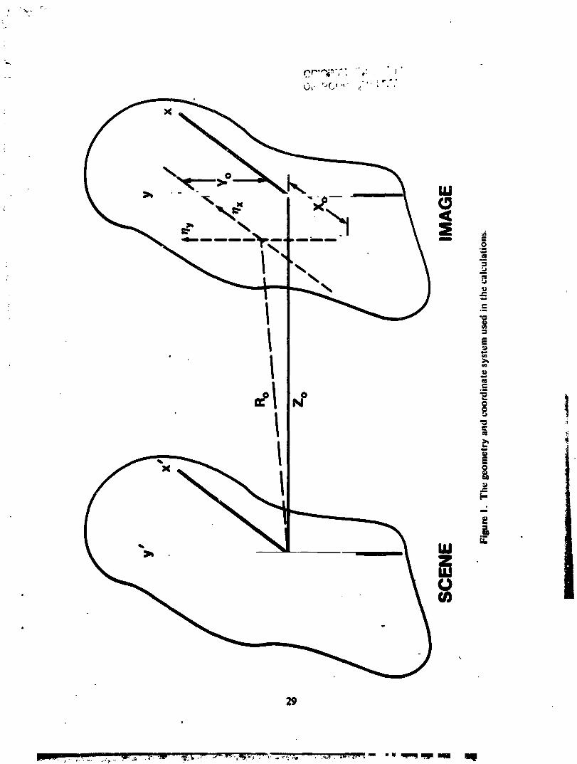
1 The geometry and coordinate system used in the calculations .................... 29
2 Receiverfor measuringthe correlationfunction ............................... 30
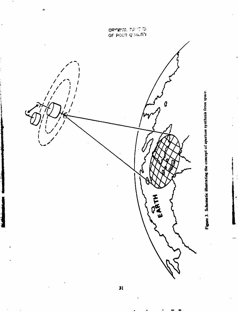
3 Schematic illustrating the concept of aperturesynthesis from space ............... 31
iv
°°
1983028268-005

I. INTRODUCTION
Microwaveradiometersin space possess a significant potential for monitoring the earth's
environment. Of currentinterest, for example, are microwaveatmospheric sounders to complement
infraredand visiblesensors. Unlike infraredand visibleradiation, microwaveradiation can penetrate
cloudsand could providemeteorological data in the important regions beneath clouds and inside
storms. However,microwave sensors in space requirerelatively largeantenna systems and antenna
size ultimately imposes limits on the spatial resolution practical with such sensors. This paper
describesa technique to help overcomethese limitations.
The technique involves coherently measuringthe product of the signal from pairsof antennas with
manydifferent antenna spacings. Eachantenna pair measuresthe correlation function of the
antenna voRag¢,R(x), at an argument,x, determinedby the distance between the antennas. For
" "distant sources, it can be shown that the correlationfunction is proportional to the Fourier trans-
form of the intensity of the source at a frequency which depends on the spacing, x. Thus, by
making measurementsat many different spacings one, in effect, determines the spectrum of the :
intensity of the source. The intensity can be obtained after all measurementsare complete by
invertingthe transform. The resolution obtained in this manneris determined by how well the
correlationfunction has been measured,not by the size of tlm antennas used. Thus, in principle,
one can obtainvery high resolution maps of the source by measuringat nthly differentbaselines
usingrelativelysmallantennas.
This technique has been successfully employed by radio astronomersto obtain very high resolution
mapsof radiosources in what is called earth rotationsynthesis (Swenson and Mathur,1968;
Brouw, 1975;Hewish, 1965). The Very.Larp Array in Socorro, New Mexico is an example.
However,applyin8this techniqueto radioml_m in sp_ involvessome problemswhich aredif-
ferentflum thou facedby theradioastronomer.Forexample,theobjectsto bemappedin radio
astronomy8rerelativelysmallin angularextentand arequitedistantwhereastheearthis a"
1
1983028268-006
relatively largeand nearby source for a radiometerin space, even one in geostationary orbit.
It will be shown below that the problemsof mappingnearbyextended sourcescan be resolvedby
controlling the field of view of the radiometerby properchoice of the antennas and filters used
in the co'relator. Severalversionsof this tect'miquehave also been proposed for remotesensing
from space. These include a proposal(Schanda, 1976, 19"/9)in which the baselineis changed by
makingmeasurementsat different frequencies, a concept (Mel'nik,197:2)involvinga moving
system with a single fLxedbaseline in which measurementsmust be madeat severaldifferent time
delays, and a modification which employs a scanninglineararraywhich is rotated (C. Wiley,
privateconmmnications). These systems can all be reduced to common principleswhJ_:hsre the
sameas those employed in earthrotation synthesis.
The purposeof this paperis to develop the mathematicalfoundation for the concept of aperture
synthesis as appfiedto remote sensingfl_m space. Severalalternativeconfigurationsfor its imple-
mentation will be discussed,but the emphasiswill be on the concepts and issuesparticularto
microwaveremote sensingfrom spacerather than on the details of system design. In the sections to
follow, the responseof a single antennato radiationfrom the source will be computed t'wst, l'his
will be done initially in the frequencydomain (Fourier transformof Maxwell'sequations with
respect to time) by employing the vector Helmholtz equation, then the inversetransformwill be
taken to obtain the response in the time domain. In invertingthe Fourier transform,it will be
assumedthat the bandwidth of the measurement is smallcompared to the nominal frequencyof
the system, an approximationwhich fecilitates the mathematicsand is a realisticapproximation
for most microwavesensors. Next, this solution for the response of a s_ngieantenna will be tised
to obtain an expressionfor the spatial correlationfunction (i.e., the averageof the product of the
signals from two antennasat different positions). In doing so, it will be assumedthat the source
andthe maximumspacingbetween the antennasare both smallcompared to the distance between
the sougceandantennas,andit will be assumedthat tim sourceelectric fields are incoherent. With
2 _'_-
1983028268-007

these approximations, it will be shown that the inte_sity of the source can be obtained by taking
a Fouriertransformofthespatialcorrelationfunction.Methodsformeasuringthecorrelation
functionand meetingtherestrictionsimposedby theapproximationsmade inthetheorywillbe
discussed.Finally,a hypotheticalsysteminwhichthecorrelationfunctionissampleduniformly
- on a Cartesiangridwillbeanalyzeda_dexpressionswillbe d","ivedfortheresolutionand fieldof
view obtained with this sampling strategy.
1983028268-008
q
J
ORIGJI_iALPAGE V._
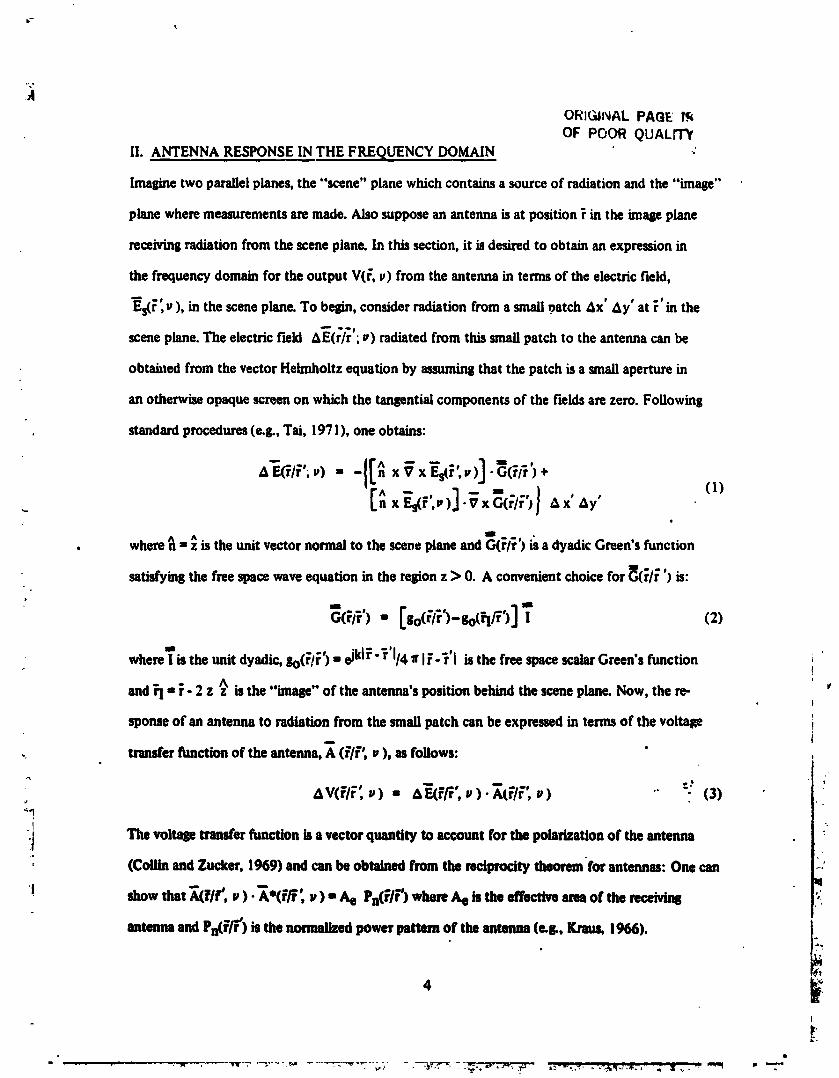
OF POOR QUALrTYII. ANTENNA RESPONSEIN THE FREQUENCY DOMAIN :
lmat_netwo parallelplanes,the "scene" planewhichcontainsa sourceof radiationand the "image'"
planewheremeasurementsare made.Alsosupposean antennaisat po_ition_ in the intageplane
receivingradiation from the sceneplane. In ridssection,it is desiredto obtainan expressionin
the frequencydomainfor the output V(_, p) from the antennain termsof the electric field,mS
Es(r ,u), in the sceneplane.To belpn,considerradiationfrom a small_atch &x' Ay' at _' in the
sceneplane.The electricfield &E(r/;'; _) radiatedfrom this smell patchto theantennacanbe
obtabtedfrom the vectorHelmholtzequationby assumingthat the patch isa smallaperturein
an otherwiseopaquescreenon which the tangentialcomponentsof the fieldsare zero. Following
standardprocedures(e.g., Tai, 19"/1), oneobtains:
_F.(_I_';.)- -II_ xVx E-s(_',=,)] "_(_/+')+" I (I)e
II
• where_ ^"= z Is the unit vectornormalto the sceneplaneandG(_/r'j _ a dyadicGreen's function
satisfyingthe free spacewaveequation in the re=ionz > 0. A convenientchoicefor _(r/r" ') is:
'' [ ]- (z)+am
whereIisthe unit dyadic, F,o(_!_')I ejklr-_'l/4 e IF-_'I isthe free spacescalar Green'sfunction !
andrl = r" 2 z _ is the "imNpe'"of the antenna'spositionbehind the sceneplane.Now, the re-i
sponseof an antennato radiation from the small patchcanbe expressedin termsof the voltage ii
.. transferfunction of the antenna,A (F/_'; u ), asfollows: "
) = ). v) . "--:(3)M
Lj The voltage transfer function is a vector quantity to account for the poladzatton of the antenna
/
-I
, (Collln andZucker, 1969) andcanbe obtainedfrom the reciprocity theoremfor antennas:One can
! showthat A(elf', p ) •Ao(_/P', p) - Ae Pn(_IP')whereAe is the effectiveareaof the receivins
antenna and Pn(F_) is the normalized power pattern of the antenna (ec&, Kmus, 1966). t_
4
I
........ _- "'- - _,' _ _ =.,,_"_ " -F"
1983028268-009
o__ PAOEI_OF POOR QUALITY
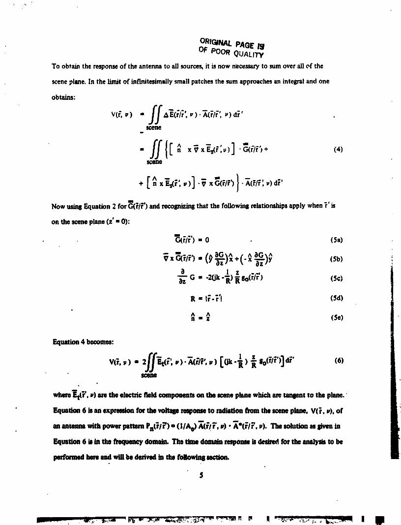
To obtain the response of the antenna to all sources, it is now n_cessary to sum over all of the
scene plane. In the limit of infinitesimally small patches the mm approaches an integral and one
obtains:
v(_,,) = ff,,,'_(rlr',, )._6I_',,) d;' t
scelte11,
- ff{[= ,,,
Now usinfl Equation 2 for _(EIr) and recognizing that the following relationships apply when _' is
on the scene pl=ae (z' • 0):
_/;') - o (s,,)
-_}x T_)y (Sb)
G = -2(jk- ) '_ go(_l_) (5c)
P,= I_'-'_'I (Sd)
Equation 4 becomes:
,ff k " '"V(_, i, ) = r'; ,)- 7k(_/_;, ) [Ok- ) "_
where_tCr',_)aretheelectricfieldcompowmon thescenephnewhichare_t to thepbM.
• ]_lUlbn 6 18II! t_prellJon for b voitsp rNpoase to n_l_tio_ from tl_ _ pl_, V(r, _), of
An8ntenn8 with power Inlttern Pn(_/_') e (IIA e) _(r'/_', _). _e(;/[7 _). The solution as given in
Equstion 6 i_ in the frequenc_ domaim Tho time domain respomm is desired for the mudlnfls to be
$
] 983028268-0] 0
" OR:GI,NAL ;-,,+" '"_,. !_ " :
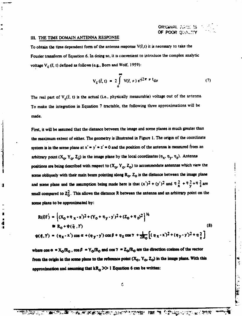
OF POORQ',_...:'_f "- +IlL THE TIME DOMAIN ANTENNA RESPONSE
To obtain the tunedependentform of the antenna responseV(_,t) it is necessaryto take the
Fourier transformof Equation6. In doingso,it isconvenientto introduce the complexanalytic
voltageVc (P,t) def'medasfollows(e.&, Born andWolf, 1959):
cIo
Vc(F,t) = 2J V@,v) e-j_ff v tdv (T)O
The real part of Vc(r, t) is the actual (Le., physically measurable) voltage out of the antenna.
To make the integration in Equation ? tractable, the following three approximations will be
made.
iFirst, it will beas_med that the distancebetweenthe imageandsceneplanesismuch ipreaterthan
the maximumextent of either.The geometryisillustratedin Fism-ei. The oril_ of the coordinate
systemis in the sceneplaneat x' - y' = z'" 0 and the podtion of the antennais measuredfrom an
arbitrary point (X o, Yo, Z_) in the imageplaneby the localcoordinates(qx, _y' qz)" Antenna
positionsarebein8describedwith respectto (Xo, Yo, Zo) to accommodateantennaswhich viewthe Ii
sceneobliquely with their main beam pointins alonSRo. Zo is the distancebetweenthe imageplane
;l and scene plane and the assumption bein8 made here is that (x') 2 + (y')2 and fl x2 + Yly2+ y/i are ,
smallcompared to Zo2 . This allows the distance R between the antennaandan arbitrary point on the i "
I
I
sceneplane to be approximatedby:
+'. - l(Xo*',x-x')2• +',,-y',::+(Zo+.,,,.;--}4:. =' Ro+,I,(_ .+') (8)
_f('_,?') " ('X" x')cos a +(,y. y')¢mD + _lz cos'Y *_ [( fl x" x') 2 y')2 + q 2z ]
wlweoosa "Xo/Ro.cosig -Yofltoudcm'Y = Zo_mretbe_cosiemofthevect°f
fromtUoo_st.tumemaneplmtome_enmc._,nt(Xo,Yo.Zo)inmeinu__ _m _
approximationiusclumuntn8thaikllo>> ! Equalion6 ambewritten:
_..+.+++_;,.++.+,",-_.,,;_.,+++_+.++_+_-_+_+,_+_;_++ +._.++++._+,,_ _ -'++*=,,,._+,+-.++.,.,-+,;_++_ +-,,_,,, , _,+,. +*+_',p+ +,,,+-.+*_+.+k;.
1983028268-011
x , aw '¢ _ a
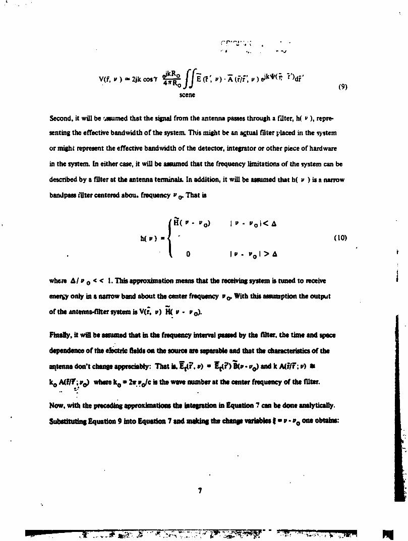
V(f.v ) _"2jkcos? _kR° ffE_'4;Ro ,v).A (_'/_",v )eJk_(_ "'r)d_' (9)scelle
Second, it _!1 be .'4mined that the sismd from the antenna passes throush a f'dtcr, h( _ ), repm-
wntmg the effective bnad_dth of the system. This _t be an _ _ter _iaced in the _tem
or mish_ representtheeffectivebandwidth of the detector,intel_tor or other pieceof ha.-dware
in the system.In either case,it will be anaunedthat the frequencylimitationsof the _,stem canbe
describedby a filter at the antennaterminals.In addition, it will beassumedthat h( p ) isa narrow
bnadpassz'iltercenteredabou, frequencyu o- That is
H(P- vo) IP- PoI<A
h(P) - " (10)
• " 0 Ip- Uol>A *
w_re A/l, o < < !. This approximation meansthat the mceivins systemis tuned to receive i
eaetl;y only in 8 narrow band about the center frequency u o. With this assumption the output
of the nailer systemis V(_,u) H( u - po).
Fim_, it will be mmmugl that in tha fmqumtcy _ imm_l by the filter, the time nad spece
dependence of tim efectrh: fhdd8on the soutge m _ mtd that tlw chmagterkltics of the
antenna don't chanl8 appredably: That b. gt(F. u) ,, gt(i 7)_J(t,. Po)andk A(F/T; u) am
koAffff.;%) whereko - 2f%/c istimwavenumberatthecenterfrequencyof thetriter... ;'_
Now. xmUm muaUou ca,,be UUy.
_ EqusUou9 _o EquaUon"_andmk/ns the chance_ _- u- % oue _:
7
| T .., , m _m_
1983028268-012
% • °.
OR'GINALPAGE i$OF POOR QUALITY
b
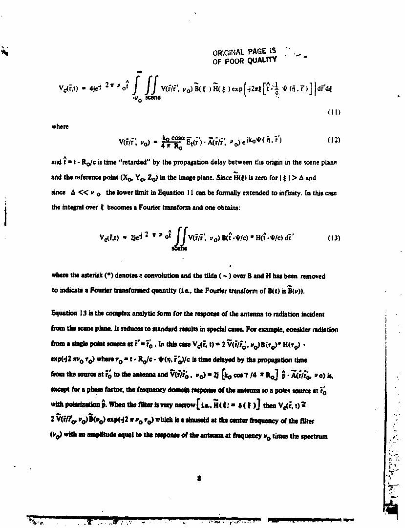
-V 0 scefle ".
(11)
where
4fg 0 i..
and_ ,, t - go/c is time"retarded" by the propaliatJondelay between the originin the _ene plane
andthe referencepoint (Xo, Yo, Zo) in the imalieplane. SinceH(_) is zero for I_ I> &and
since & << p o the lower limit in Equation i I can be formallyextended to inf'mity,in tl_ case
the intqltal over_ becomesaFouriertransformandoneobtains:
I2 "V_F,t) • 2je"j2 7 Po_ V(_I_" uo)B(t._k/c)" H(;'.4,/c)d_' (13)
wheretheut_isk (') dehornp.convolutionandtherims( ~ ) over B and H hw been removed
toindicatea Foug_'tnumf(mnedquantity(Le..theFout_r tranafomofB(t)isBO,)).
$
.- L_ I
1983028268-013

of the source at vo. In the other extreme, when the filter is very broad {i.e., H(r) = 60")], then
Vc(_', t) _- 2 V(F/Fo, Vo)BO-o)exp(-j2 _rvo 1"o)which again is a sinusoid at the center frequency
of the f'flterbut in this case modulated by the time dependence of the radiation from the source.
m
9 u,
1983028268-014
%
OF i_U_ (_'.'AL.;.TY.
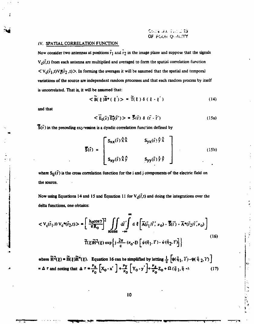
IV. SPATIAL CORRELATION FUNCTION
Now considertwo antennasat positionsrl andr2 in the imageplaneand suppose'.hat the signals
Vc(r,t) from eachantennaaremultiplied andavenged to form the spatialcorrelationfuv.ction
< Vc(ri ,t)V_(r 2 ,t)>. In formingthe averagesit will beassumedthat the spatialandtemporal
variationsof the sourceare independentrandomprocessesandthat eachrandomprocessby itself
is uncorrelated. That is, it will be assumed that:
<_( _)_.(_')> - T_ )_( _- _') (]4)and that
• S(r) in the preceding ex_,-ession is a dyadic correlation function def'med by14
_'(r) = (15b)
wimm Sij(_) is the crosscorrelationfunction for the i and j componentsof the electric field on
the source.
Now using Equations 14 and I$ and Equation II for Vc(_,t) and doing the integrations over the4
delta functions, one obtaw,s: _
QO
<vc61,t)vc*62,t)>'[k°°_12 ff _ [A( A(r2/r,Wo) 1WJ dr d t _1/_: Wo). "_(;') .--* " "'sCelle .oo
(16)
qwhem_2(_) = _(_)_'(_). Equation 16 can be simplifled bylettin81 _k(_l,r')"_(_ 2,r')]
[Xo..' [Yo-,'Zo-," ,,,,_, = A r and noting that A *"= _Wo PO
i
10
'"
--,;. _. ......... ; ". ,tsqt_isl_sm_ _ ...... .., - -.; ,- ; • _r" _. • . • 2-. _'q
1983028268-015
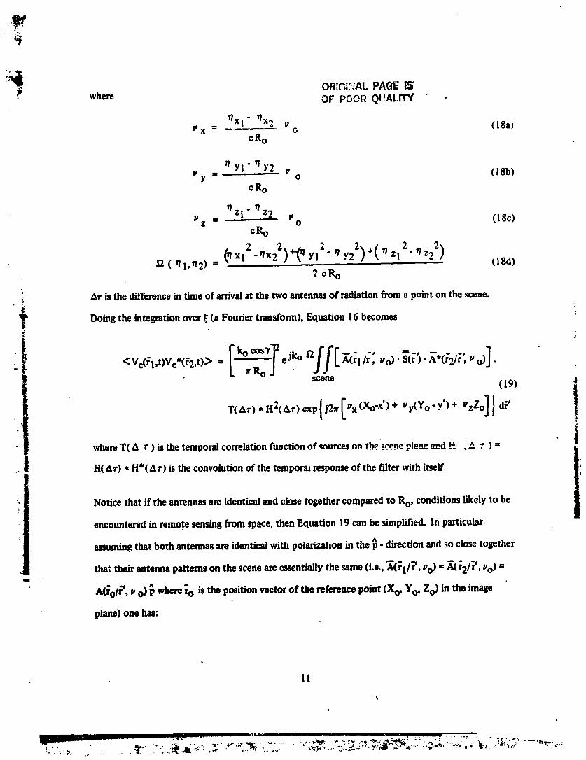
i_' ORIC_?JALPAGE IS, where OF POOR QUALITY
_Xl" _x2 v (lSa)V X -- O
c_
Y!'_Y2 v (18b)P ==y o
c_
Zl z2='z = Vo (18c)
Ce-o
2. _/ )+(O ZI2"T? Z22) tl8d)12(_1,.2) = (" _'_"xx12"_x22" " Yl Y222cRo
ar is the differencein time of arrivalat the two antennasof radiationfrom a point on the scene. ,
f Doing the integration over _ (a Fourier transform), Equation16 becomes
<Vc(_l.t)Vc*(F2,t,> ." ['k°"c°sT"eJkooff[ .o)" .o)JL 1_J •scene (19) |
!where T( _ _") is the temporal correlation function of ,_ure._ nn the ._cene pl_e _.d .q-- _A r ) = |
H(&r) * H*(A_ ") is the convolution of the temporal response of the f'dterwith itself. 1;'
INotice that if the antennas are identical and close together compared to Ro, conditions likely to be
encountered in remote sensing from space, then Equation 19 can be simplified. In particular:
assuming that both antennas are identical with polarization in the _ - direction and so close together
that their antenna patterns on the scene are essentially the same (i.e., _([1/_', =,o) = _.(r2/r', z,o) =1
A(rol [°, ='o) P where 1o is the position vector of the reference point (Xo, Yo, Zo) in the image
plane) one has:
11
",°
q
1983028268-016
OR|,r_._,',DL" "
OF PO0_ Q_ALi'I'_XGI/;',,,0)s_;'_.X.G2/;',,'o_:
--- ^]_- A(_o/i", "o) A*(fo/F; J, o) • S(r ). p (20)
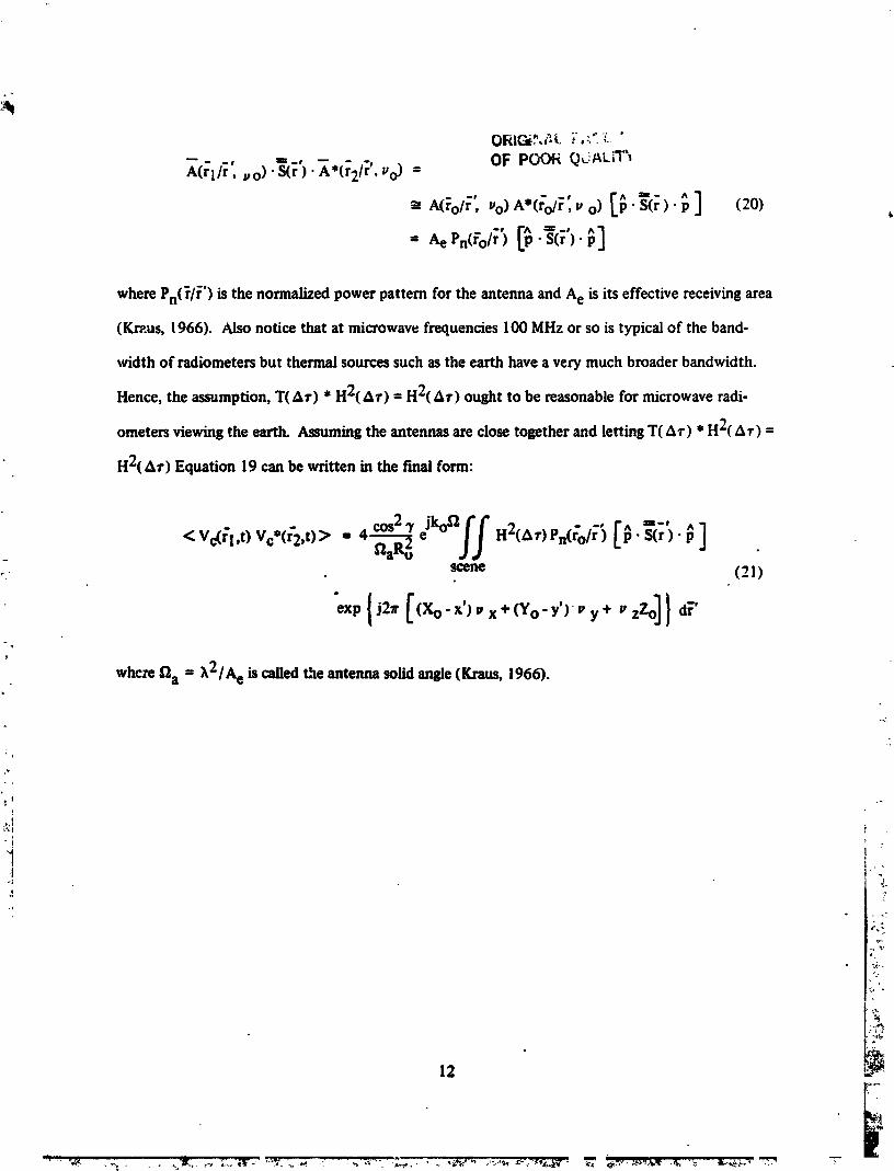
where Pn(_/_') is the normalized power pattern for the antenna and Ae is its effective receiving area
(Kr_.us, 1966). ALsonotice that at microwave frequencies 100 MHz or so is typical of the band-
width of radiometers but thermal sources such as the earth have a very much broader bandwidth.
Hence, the assumption, T(&_') * H2(A¢) = H2(Ar) ought to be reasonable for microwave radi-
ometers viewing the earth. Assuming the antennas are close together and letting T(A_') * H2(A_') =
H2(Ar) Equation 19 can be written in the f'mal form:
< Vc(171,t)Vc*(r'2,t) > = 4 cos2 3' "
scene (21 )r-
y �,,,o]}whc:¢ fl a = _,2/A0 is called the antenna solid angle (Kraus, 1966).
12 ._
" °_,_. , .:,,-. . . ,.'SI_,__ -_:'.__T1r. _-:'_- _ .: :,./-_--: ,,,.,.,.... ,,_.%,., ..,_:._,_,_--_._,_,_.;,,9,-_ _ _,.. :._,_,.,t ,,_ -_ : _-< �<�-..,
1983028268-017
QF- ,.,......
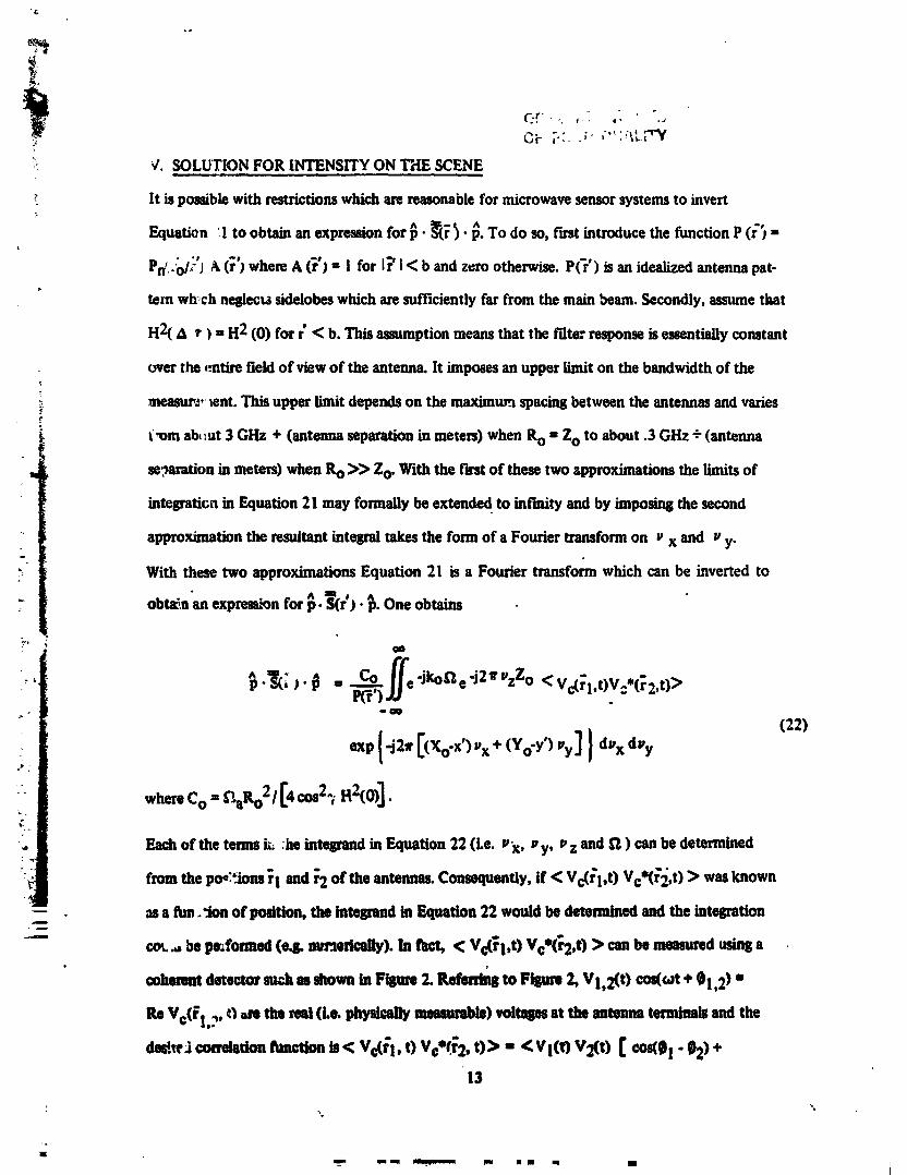
'-_ '_.SOLUTION FOR INTENSITY ON THE SCENE
It is possible with restrictions which are reasonable for microwave sensor systems to invert
Equation I to obtain an expressionfor_. _'). _. To do so, firstintroducethe function P(r'_ ,,t
Pd .ol_-'J&(r'J where A (r') = 1 for I_' I< b and zero otherwise. P(_') is an idealized antenna pat-
tern wh,ch neglects sidelobes which are sufficiently far from the main beam. Secondly, assume that
H2( £ t ) -- H2 (0) for r' < b. This assumption means that the t'llterresponse is essentially constant
overthe ,entirefieldof view of the antenna.It imposesan upperlimit on the bandwidthof the
nteasuv._,tent. Thisupperlimitdependson the maximur:tspacingbetween the antennasand varies
t,om al_:ut 3 GHz + (antenna separation in meters) when Ro - Zo to about .3 GHz - (antenna
,, se,_mrationin meters)whenRo >> Zo, Withthe f'erstof these two approximationsthe limitsof
integration in Equation 21 may formally be extende d to infinity and by imposing the second
approximation the resultantintegraltakes the form of a Fouriertransformon _'x and g'y.
With these two approximationsEquation 21 is a Fouriertransformwhich can be inverted to
obtz_n'anexprem;'Qnfor _. T(r'). _. One obtains
' _.,_ ). _ = _ e'Jk°fle'J2_vzZ° <Vd_l,t)V=.(_2,t)>
(22)
wbereCo = _aRo2 / [4 cos23 H2(O)]•
Eachof the termsi;; :he intesrandin Equation 22 (Le. p x, py, p z and %2) canhe determined
fromthe and ofthetems. if <Vc('l,t) > wasknown
-- as a ftm._lon of position, the interbred in Equation22 would be determinedandthe integration
-"- cot._, beL_formed (e& mn_edodly). In fa_ < Vc(_l,t) Vce(_2,t) > canbemeasturedusinga
coherent detectorsu,_hmssitownin FtStue2. Refen_ to Flllum2, Vl,2(t) cos((ot + 01,2)"
ReYc(_!.?, O ,re timreel (Le. physicallymeammbht)volteses at the antena terminalsandthe
13
m,m mmm_m.,..m _ mmm . mm I
1983028268-018
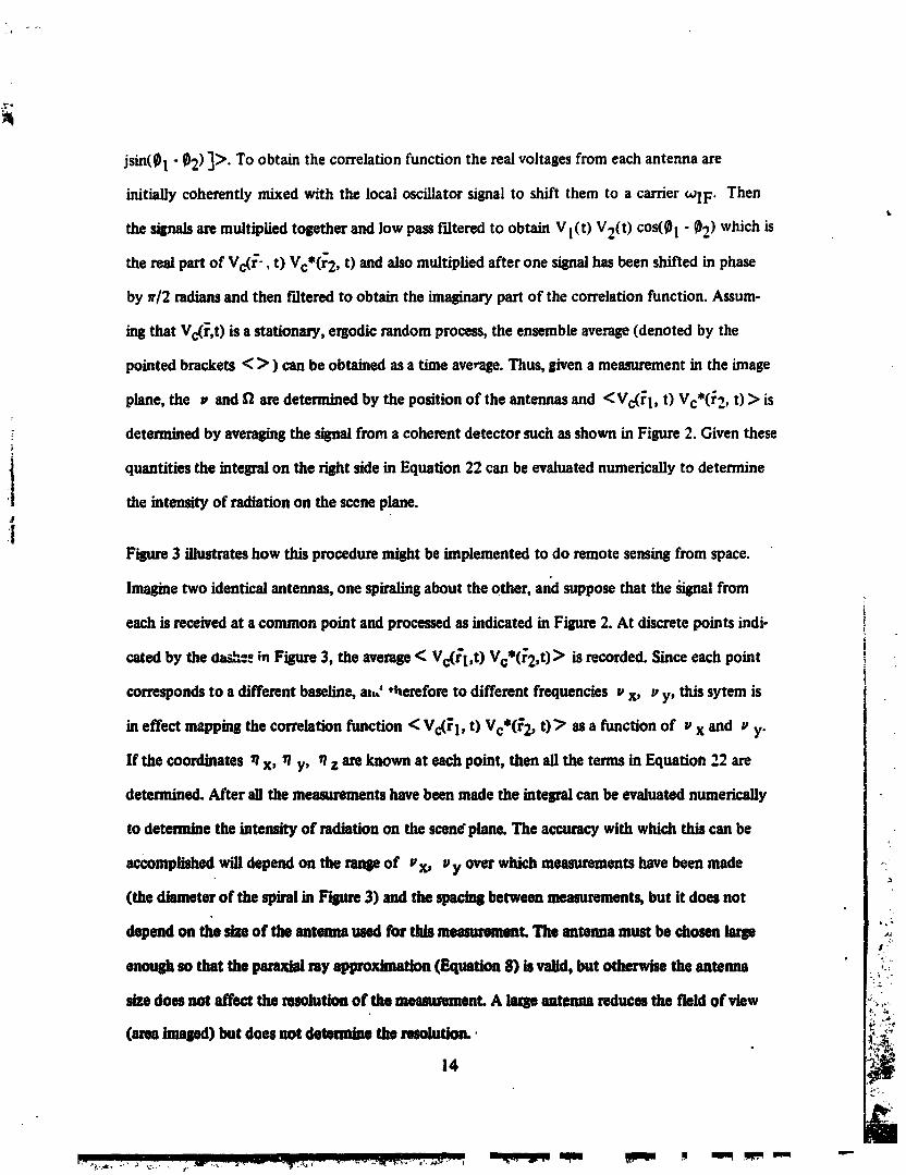
jsin(_! - _2) ]>. To obtain the correlationfunction the realvoltagesfrom each antennaare
initially coherently mixed with the local oscillator signal to shift them to a carrierWlF" Thent.
the signalsaremultipliedtogether and low passf'flteredto obtain Vl(t) V2(t) cos(_)1 - _)2) which is
the real partof Vc(r'-, t) Vc*(r2, t) andalso multipliedafter one signalhas beenshifted in phase
by a'/2 indiansandthen filtered to obtain the imaginarypartof the correlationfunction. Assum-
ingthat Vc(r,t) is a stationary, ergodicrandomprocess, the ensemble average(denoted by the
pointed brackets < > ) can be obtainedas a time average.Thus, given a measurementin the image
plane, the v andf2 aredeterminedby the position of the antennasand < Vc(rI, t) Vc*(r2, t) > is
: determinedby averagingthe signal from a coherent detector such as shown in Figure 2. Giventhese
i quantities the integralon the rightside in Equation 22 can be evaluated numericallyto determinei the intensity of radiationon the scene plane.J
:1Figure 3 illustrateshow this proceduremight be implemented to do remote sensingfrom space.
Imaginetwo identical antennas, one spiralingabout the other, and suppose that the _;nal fromi
each is re_ived at a common point and processedas indicated in Figure2. At discretepoints indio
caredby the ¢tas_._in Figure3, the average< Vc(r'l,t) Vc*(_2,t)> is recorded. Since each point It
correspondsto a different baseline,all,' ,t_ereforeto different frequencies z,x, z,y, this sytem is
in effect mappingthe correlationfunction < Vc(_1, t) Vc*(_'2,t) > as a function of _,x and _,y.
If the coordinates _ x, _ y, _ z areknown at each point, then all the terms in Equation 22 are
determined. After all the measurementshavebeen made the integralcan be evaluated numerically
to determine the intensity of radiationon the scene"plane. The accuracywith which this can be
accomplishedwill depend on the ran_ of vx, I,y over which meesurementshavebeen made
(the diameterof the spiral in Figure3) and the spacingbetween measurements,but it does not
depend on the size of the antennaused for this meesumment.The antenna must be chosen large
enot_ so that the _ raysp_o_lmation (Eqtmtion8) is velid, but otherwise the antenna
size does net affect the resolution of the meammment.A largeantenna reducesthe field of view
(areaimaged)but does not determine the nmolution..
14
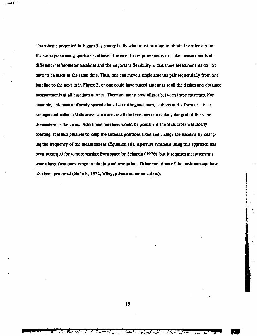
The scheme presented in Figure 3 is conceptually what must be do._e to obtain the intensity on
the scene plane using aperture synthesis. The essential requirement is to make measurements at
different inteferometer basel/nes and the important flexibility is that these measurements do not
have to be made at the same time. Thus, one can move a single antenna pair sequentially from one
baseline to the next as in Figure 3, or one could have placed antennas at all the dashes and obtained
measurements at all baselines at once. There are many possibilit/es between these extremes. [:or
example, antennas ur,iformly spaced along two orthogonal axes, perhaps in the form of a +, an
arrangement called a Mills cross, can measure all the baselines in a rectansular grid of the same
dimensions as the cross. Additional baselines would be possible if the Mills cross was slowly
rotating. It is also possible to keep the antenna positions fixed and change the baseline by chang-
ing the frequency of the measurement (Equation 18). Aperture synthesis using this aI_l_'oachhas
been._e,d for remote sensing from space by $chanda (1976), but it requires measurements
over a large frequency range to obtain good resolution. Other variations of the basic concept have
also been proposed (Mel'nik, 1972; Wiley, private communication), iIJ
£
l,
IS
mira
1983028268-020
_t u_;'._'_L _A, c, !_ "OF POOR QUALITY -"
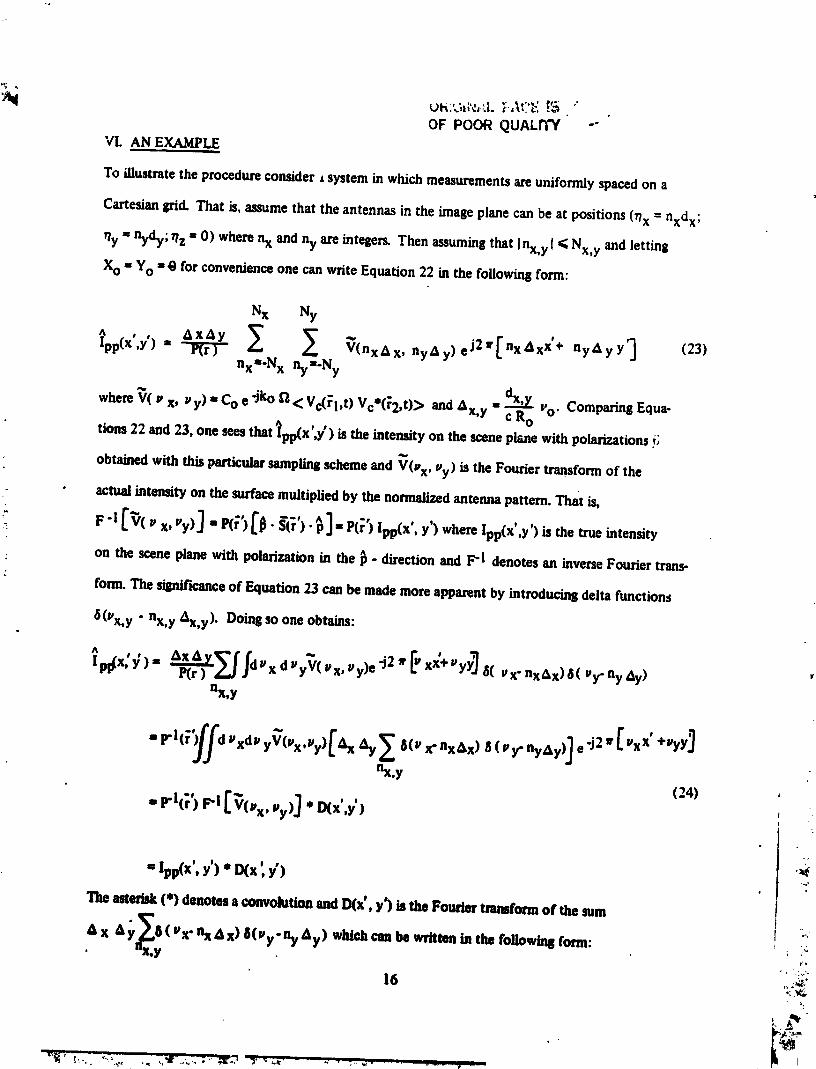
VI. AN EXAMPLEi
To illustrate the procedure consider • system in which measurements are uniformly spaced on a
Cartesian grid. That is, assume that the antennas in the image plane can be at positions (rlx = nxdx;
_/y= nydy; l?z= O) wherenx and ny are integers.Then assumingthat Inx,y I _ Nx,y and letting
Xo = Yo =@ for convenienceone can write Equation22 in the following form:
Nx Ny
pp(X,y) = V(nx_ x, nyAy) eJ2W[ nx_xx+ ny_yy_ (23)nx--N x ny--Ny
dx'y ComparingEqua-where _( v x, v y) - Co • -jko _ <_Vc(_l,t) Vc*(_2,t)_> andAx,y - c Ro _'o"
tions22 and23, one seesthat_pp(X',y') is the intensityon the sceneplanewith polarizationsi;
obtained with thisparticular samplingschemeand V(_ x, _,y) is the Fourier transform of the
• actualintensity on the surfacemultiplied by the normalizedantennapattern. That is,
; on the sceneplanewith polarization in the _ - direction and F"1 denotesan inverseFourier trans-
form. The significanceof Equation23 canbemade more apparentby introducingdelta functions
8(Vx,y " nx,y _x,y)" Doingsoone obtains:
P(r )
nx,y
2 ['x"+YJflx,y
(24) !
=Xpp(X°,y')*_(x',_')The asterisk (*) denotes 8 convolution and INx', y') is the Fourier transform of the sum
x _y_( _x"nx_x) 8(_y.ny AF) which can be written in the followinll form:
Imlmnt
"X,¥
16 "_
'19830282 8-
ORIGtr."; L '-'"
OF PGCR C,._'::4Lri3f
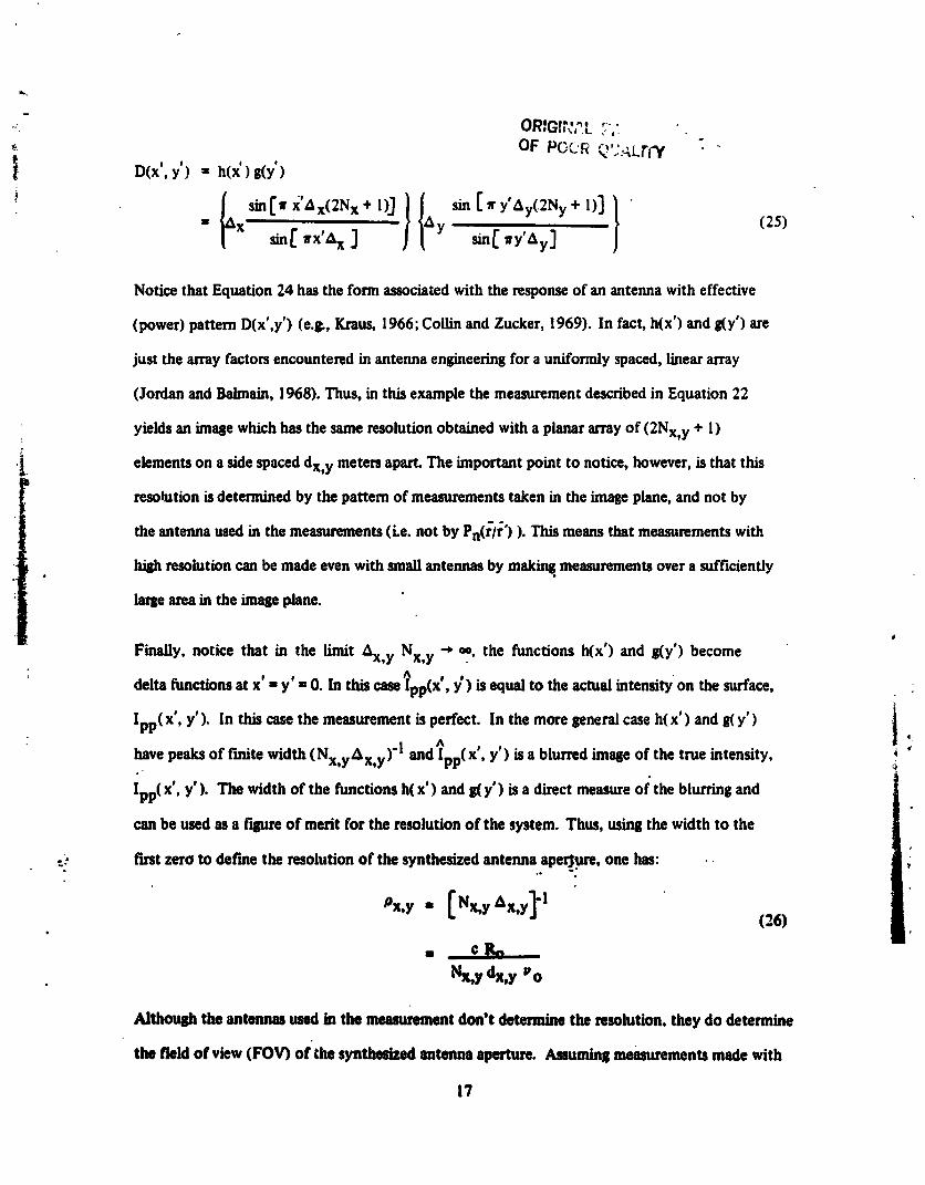
I D(x',y') - h(x')&,(y')?
_ sin[Irx',_x(2Nx+l)_//_ sin[Iry'Ay(.2Ny+l)]} "" ' x sin[a'x'_kX ] Y sin[fy'Ay] (25)
Notice that Equation 24 has the form associated with the response of an antenna with effective
(power) pattern D(x',y') (e.&, Kraus, 1966; Collin and Zucker, 1969). In fact, h(x') and g(y') are
just the array factors encountered in antenna engineering for a uniformly spaced, linear array
(Jordan and Baimain, 1968). Thus, in this example the measurement described in Equation 22
yields an image which has the same resolution obtained with a planar arrayof (2Nx,y + 1)
•_. elements on a side spaced dx,y meters apart The important point to notice, however, is that this
resolution is determined by the pattern of measurements taken in the image plane, and not by
the antenna used in the measurements (Le. not by Pn(r/r') ). This means that measurements with
high resolution can be made even with small antennas by making, measurements over a sufficiently
large area in the image plane.
it
Finally, notice that in the limit Ax,y Nx,y -* m, the functions h(x') and g(y') become
' delta functions at x' = y'= 0. In this case _pp(X', y') is equal to the actual intensity on the surface,
Ipp( x', y'). In this case the measurement is perfect. In the more general case h(x') and 8(Y')4,
of f'mite width (Nx, y Ax, y)'I ^have peaks and lpp(X', y') is a blurred image of the true intensity,,
Ipp( x', y'). The width of the functions h(x') and 8(y') is a direct measure of the blurring and
can be used as a f'_u_ of merit for the resolution of the system. Thus, _8 the width to the
-? tint zero to define the resolution of the synthesized antenna aper$_re, one has: •
126)
Nx,¥ d_y Po
Althoush the antennu used in the measurement don't determine the resolution, they do determine
the field of view (FOV) of the synthesized antenna aperture. Assuminll measurements made with
17
1983028268-022

It"* '_" _ ;OR,_._,,t,...- ,:_t_ OF POOR ¢_ :""" "" --
antennaswith din.ensionsDx,y in the x- andy-directions,respectively,the portion of the scene
plane from which energy is received is approximately:
X cK
FoVx,y= Ro-where Ro is the distance from the antenna to the scer.e plane. However, several restrictions haveel=
been imposed on this field of view in the course of developing the theory. First, the field of view
must be much smaller than the distance between the image plane and scene plane to satisfy the
sagittal appmxnnation (Equation 8) made in the derivation of the antenna response (Equation 9).
Using Equation 27 this restriction may be stated as:
¢
<< 1 (28)Dx,y v o
(The sagittalapproximationalsolimits thesizeof the array possiblein the image plane,but con-
: sidering that Ro is large for sensors in space, this is not likely to be a significant restriction.) Second,
-ithe array functions h(x' ) and g(y') have grating lobes which affect the field of view. These grating
lobes occur every !/& meters; hence, for unambiguous measurements the field of view mustx,y
be restricted to be less than this distance:
I
FOVx,y _ _ = Nx,y Px,y (29)
ComparingEquations27 and29, one finds,that dx,y _ Dx,y to avoidgratinglobes.
Combininl_theseresults,oneobtainsthe following parametersfor the imase formed with this
measurementscheme.Assumingmeasurementsfrom analtitude, Ro, at a frequency,z,o, with
antennas of size, Dx,y on a side. and assuming 2Nx.y + ! measurements uniformly spaced dx,y
meters apart on each side, one obtains:
Remlution
(3o.)PX,y = (Nx,ydx,y) t,o
Field of ViewcRo
FOVx,y = _ (3Oh)
18
,_ : J _ _ _1 -w -- I -- i.
1983028268-023
For no Grating Lobes
dx,y .t Dx,y f'_nc)
To satisfy the Sagittal Approximation
C<< I (30d)
UoDx,y
o.
o.
19
1983028268-024

Ib
VII. CONCLUSIONS
Notice that in the preceding example, Equations 30a-c are just the parameters associated with the
antenna beam of a linear array with uniform element spacing dx,y and Nx,y elements on a side.
That is, the image synthesized with the uniform sampling scheme described in the example will be
the same as one formed by.scanning with a linear array which occupies the same region in the image
plane as was used to obtain the synthesized image (Equation 22). However, the unique advantage
of the synthesis procedure is that all of the antennas do not need to be present for each measure-
ment. In principle, the image could be formed with just two antennas which are moved to appro-
priate positions in the image plane.
Also notice the special role played by system bandwidth in the synthesis scheme. The field of view
obtained with aperture synth_._s and with a 5near array with an equivalent resolution are determined
• by the elemental antennas used in the measurement; however, in the case of aperture synthesis the
field _,fview is also affected by the bandwidth of the measuring system. For example, consider an
ideal f'dter with response H2(_,: ")= H2(0) for _,:"< :'c and 0 otherwise. Radiation from a point sym-
, metrically located below a pair of antennas (i.e. equally distant from each)arr/ves at each antenna
at-the same time (i.e. _" = 0); however, as one moves away from this position the time delay . •
increases. When the delay exceeds _'cradiation from this position no loner ispassedby the t"dter.
i Consequently, the f'dterhas the effect of rest_tins the field of view. To a f'_rstapproximationI
i (Xo • Yo • 0 and Ro much later than the field of view) this distance is cRo/dx,y A wherei
A .is the system bandwidth (4 =' r _ ) and dx, y is the distance between antennss. In the
analysis presented above it was assumed that H2(,_ r) • H2(0) for points within the field of v/ew
determined by the antennas. That is, the field of view set bv the filter was chosen to he much
8ruter than that set by the antmmas _ However, it is also pomible to use the filter itself
to control the flekl ofview. The difficulty is that At, and therefore the field of view, depend on
the Conuc a. to keepthe of view
20
1983028268-025
must be changedfor each measurement.This may not be so impracticalas it seems if, for example,
the data fromeach antennawas re_,ordeddi_tally with a fixed bandwidth and then processed
laterto obtain the correlat/onfunction. The f'flteringin this case could be done numericafiyas part
of the processing. Such a procedurewould haveverygreat flex/bility in choosingthe field of view,
'. but it requiresveryImp bandwidth duringthe initial recordingprocess.
Anotherpoint to consideris the sensitivityof the synthesizedaperture(i.e., the accuracywith
which the source can be determinedwith a givenaveragingtime permeasurement). To give an idea
of the sensitivityachievedwith aperturesynthesisa comparisonwiththesensitivity of a tineararray
has been made. Th/s is presentedin the Appendix. It is shown in the Appendix that for point
sourcesthe realapertureis moresere/rivebecause its narrowbeam restrictsthe backgroundagainst
which the source must be contrasted,whereasin the case of aperturesynthes/s the antennas view
the mtUrefield of viewoneachmeasurm_nt However,forextendedsourcessuchastheearth,
which fill the field of view, the reed.apertureandsynthetic aperturesreceive the stonepower density|
on eachmemuremantandthereforeareequallysensitive.Hence.for remoteseminliof theearth
from space, aptn_ synthesis can providesens/tivity comparableto a real aperture.
Finally,comkl_ the effects of antennaposition errmson the _ obtained with the synthe_s
sdteme. An error A_i in antenna reparationalong the i-th coordina_.b equivalentto an error
&Pi in spatial _ (Equation 18). In order forthis _nrugto t_ havea mudl effect on the
ima0eonemclutmsOEquation22)that Apit-(-_/--_Ro << I w_m _,o is the wavelansth., {CXo,.,').e,'o,,y').the s_Isl Splxeeahm,t_ (Equm/_ 7) it lumbmn _umml that x'/Ro<< I mufy'/Io << I.
llmu_ flu _ tlm _Ition mms Ime amll ofre_ on t_, _ am be _
mo mmmtm of the mlllas t_t tim tmmmo(tke mZmam mini ia the syatluJs _ au_
_I, _. flare, _h=_ a_mm _ Im_ Immd_ to mm In t_ _m _
21
1983028268-026
to the imaqleplane (_77x and _TTy)by restricting the antennasto point near nadir. On the
other hand, except in extreme cases Zo _ Ro. Consequently, errors in "he position perpendicular
to the imsle plan_ are particuhu'ly critical andneed to be muchlessthan a wavelength.Similar
commentspertain to the I/near array. However,notice that the requirement m the synthesispro-
_lure is on/)" for knowledp of poau/tion,and that the pos/t/_n itself is not particu/ady important.
If the posit_n is known, evenif it is many wavelenllthsfrom the des/redposition, then appropri-
ate correctionscanbe madein proceui_ .he data by ad_tinl the phasetermsin Equation 2_.
"j
J, ,s
nunuuu _. _ SllmSumul m _ESn s= p_,,ll _ _ "4_
1983028268-027
_, ,% •t, -
VIII. SUMMARY| i ii
A theoretical basis .hasbeen presented for synthesizing antenna apertures for microwave radiometersT
in space. The technique consists of measuring the product of the signal from pairs of antennas
at many different antenna spacings, thereby mapping the correlation function of the antenna
voltage. The intensity of radiation at the source can be obtained from this correlatior function by
means of a Fourier transformation. A variety of procedures are possible to measure the correla-
tion function, including a pair of antennas with variable baseline, an array of antennas which simul-
taneously make m.. surements at many baselines, meastuements with fixed spacing but at several
: frequencie _, and combinations of these. For mapping the earth from space all of these schemes
• ,,_ must limit the field ofview in order to guarantee a Fourier transform relationship between the|
intensity on the scene and the correlation function. The resolution obtained with these schemes!
- i is similar to that of a real linear arrayof the same dimensions in the image plane. The major
ciifferences being that the synthesized image is obtained by _ processing after all measurements!
are made and that the field of view of the synthesized aperture must be restricted to meet the
paraxial ray approximation. "lae field of view can be limited by the actual antennas employed _.
in the measurement or by controlling the effective bandwidth of the measurement. The latter
requires large bandwidth but is potentially the most flexible system.
o
•m 23
L__ILLI', I_ ,_. ,. _.u.•; , _-_- _ _1_;:.._,--- _-_, . ::_ • ,- _ _ '_ _
1983028268-028
REFERENCES
Born, M. and E. Wolf (1959), principles of Optics, Chapter 10, Pergamon Press.
Collin, R. E. and F. J. Zucker (1969), Antenna Theory, Vol. 1, Chapter 4, McGraw-Hill.
Brouw, W. N. (1975), "Aperture Synthesis", in Methods in Computational Physics, Vol. 14, "
B. Alder, Ed., pp. 131-175, Academic Press.
Hewish, A. (1965), "The Synthesis of GiaJ_tRadio Telescopes", in Science Progress, Vol. 53,
pp. 355-368.
Jordan, E. C. and K. G. Balmain (1968), Electromagnetic Waves and Radiating Systems, 2nd
Edition, Chapter I l, Prentice-HaiL
Kraus, J. D. ( !966), Radio As.tronomy, McGraw-Hill.
Mel'nik, Yu. A., (I 972), "Space-Time Handling of Radiothermal Signals from Radiators that Move
in the Near Zone of an lnterferometer', lzvestiya Vysshikh Uchebnykh Zavedenii, Radiof',Tika.
. VoL 15, No. 9, pp. 1376-1380, Sevtember.
.. i
Schanda, E., (1979), "MuRiple Wavelength Aperture Synthesis for Passive Sensing of the Earth's !
Surface", International Symposium Digest, IEEE/Antennas and Propagation Society, :
pp. 762-763, Seattle, Washington, June.
i Schanda, E., (1976), "High Ground Resolution in Passive Microwave Earth Observations from Spacet
' i by Multiple Wavelength Aperture Synthesis", Proceedings, International Astronautical!n _
t Federation Congress, Anaheim, California, October.Ii
! Swanson, G. W. and Mathur, N. C. (1968), "The lnterferometer in Radio Astronomy", Proceedings
IEEE, VoL 56, (No. 12) pp. 2114-2130. ""
Tat, C-T. (19"Y1), D]tadi.'cGreen's Functions in Electro etic Theo , Chapter 4, International
menTextbook Company.
i
.... • ,." , , > _ .:g ,' ...- ]. . ¢,mm,,.a,_ ,,m,_,.,,t.=..ms
1983028268-029
L_
APPENDIX
Although the synthetic apertme has the sameresolution as a linear arrayof comparablesize, the
imagesare formedin a much differentmannerwith each system. The lineararraymaps by forming
individualbeamswhich leceive energyfromeach resolution cell in the map (i.e., one beam per
pixel). In contrast, the synthetic aperturemakesall its measurementswitha smallantennawhich
receivesenergy fromthe entire fieldof view duringeach measurement.This raisesthe question of
the relative sensitivity of the two approaches: that is, given an available integration time per
measurement,arethere differencesin the temperatureresolution of the imagesformed with
aperture synthes_ as comparedto that obtainedwith a realarray.This question is addressedin the
paragraphsto follow where it i_ "shownthat for point sourcesthe realantenna is more sensitivebut
that for extended sourceswhich fill the field of view, aperturesynthesis and the realarrayare
equally sensitive.
For thermalsourcesthe power availablefroman antenna with normalized power pattern,Pn (0, 0)
can be expressedin termsof the equivalentblackbody temperatureof the sources in the following
_ form(e.g., Kraus,1966; this can also be derivedfrom Equation 9 in the text): _ !
!.-Ta= _ T(0,_)Pn(0,_)sin0 dOd_ (AI) .'
4 a
wheref_aiscalledtheantennabeamsolidangleandequals(directivity/4a )'I_ isaconstant
calledtheantennaeffi,.'ieucytoaccountforlossesintheantennasystem,andTaisthenoisetemp-
eratureofaresistorwhichhasthesameavailablepowerastheantenna.Assumingforsimplicity
that the temperatureis constant over the source, T(0, _) a, To , the above simpfifiesto:
Tam 17( f_ a) T° (A2)
-- I I I .
1983028268-030

'aql Orl_'::,t. " ....:'" T_ -"OF PO0_ QUA_.I'i'Y
where
_2s=_ffPn (0,_)sine d#d_ (A3) "JJ
source
TheintegrationtimeI"requiredtomeasureTawithanRMS error(i.e.,variance)ATa isdeter-
minedby thesystemtemperatureTsysandbandwidthA inthefollowingform"
e Tsys
8Ta = V At. (A4)
wheree isaconstantwhichdependsonthetypeofreceiver(e---.7foracorrelatingreceiver
and e__2 foraDickereceiver).CombiningEquationsA2 andA4,oneobtainsthefollowing
expression for r :
! r = -- (A5)
.-_ Itisdesiredtocomparethetimerequiredtoformanimageusingalargerealantennaandasyn-
I thetic aperturewith the sameresolution. To form the synthetic apertureassumethat measurementst
:[ are madeuniformlyon a cartesiangrid with 2Nx,y + 1 measurementson a side and in ordertoobtain the maximumunambiguousfieldof view assume that dx,y = Dx,y where Dx,y arethe:1
t dimensions of the antennaused in the syntliesis. Let f_a be the solid angle of this antenna and let
f_A be the solid angleof the equivalentrealaperture. The real apertureis 2Nx,y dx,y meters on a
. side andneglectingpossible differences in side lobe levels f_A = _2a/4NxNy. Using thesedef'mitions,|
the time requiredper measurementwith the real antennais:j.
eATsys . I
_'A= \,r/A STo/ \nSA / T (A6) , '
and the time requiredfor each measurement in formingthe synthetic :.eertureis: __:.,,._
\.o6to/\ • (AT)
26 [_
1983028268-031
_I_ ORIGh &L PAGE F_. "_, OF POUR QUALITY
where g2SAand _2m are the beamsolidanglessubtendedby the sourcein the caseof the large
antenna and the antenna used in aperture synthesis, respectively.
The total time required for each system to obtain an image is obtained by multiplying by the
required number of measurements. Assuming that these are the same in each case (actually, fewer
measurements are needed in synthesi., schemes which remove redundant measurements), and
assuming that each syst:m has the same bandwidth and approximately the same system temperature
and efficiency, or.=. has:
"(°'I'----= _ (AS)Ca _SA N2
where it has been assumed that 2Nx = 2Ny = N for simplicity, and the relationship _2A = _2a/N 2
has been used.
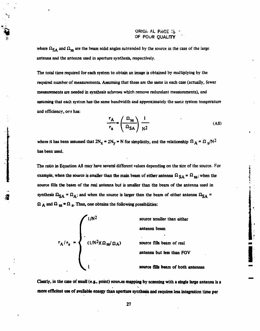
The ratio in Equation A8 may have several different values depending on the size of the source. For
example, when the source is smaller than the main beam of either antenna _'1SA = f_sa; when the
source f'tlls the beam of the real antenna but is smaller than the beam of the antenna used in
_ synthesis f_SA = _A; and when the source is larger than the beam of either antenna f_SA =
f_ A and _2 st = f_ a. Thus, one obtains the following possibilities:
/_r l/N2 so_ce smaller than either
antenna beam
rAlr a =. (I/N2)(_2st/_2A) source fills beam of real m
antenna but less than FOV I
k 1 source fills beam of both antennas "-
Clearly, in the case of small (e.&, point) soun.es mappin8 by scanning with a single large antenna is a\
more efficient use of available eneqD" than aperture synthesis and requires less integration time per
27
1983028268-032

measurement to obtain desired accuracy. However, when the source completely fills the beam of
the antenna used _a synthesizing an aperture, then aperture synthesis and scanning with a large
antenna yield comparablesensitivity. This is the situation Likelyto be encountered in remote sensing
of the earth's surface.
-2
28 '_
1983028268-033
t,
X
!
29
1983028268-034

_1_' ORIGINALPA¢-,,2;_- " - t
OF POOR QUALITY
Vl(t) cos (_t -I-_1) V2(t) cos ((_t+ _2)
LOCAL MIXERMIXER OSCILLATOR
LOW PASS LOW PASSRLTER FILTER
:,
* " LOW PASSq
]- v_v==_1_,- _1 v_v= 1_- _=1 =
Fipre 2. Receiverfornumud_ =hecorrelationhuction.
3O
_r
I
1983028268-035
pr-
_.. _ r'_, ,
OF ,- .,,_.-,
31
w _ _ m R
1983028268-036


![THE DISTRIBUTION OF SPACINGS BETWEEN QUADRATIC RESIDUESkurlberg/eprints/squares1.pdf · THE DISTRIBUTION OF SPACINGS BETWEEN QUADRATIC RESIDUES 3 It is well known [15] that the spacing](https://img.pdfslide.us/doc/110x75/5b7b644b7f8b9adb4c8c8150/the-distribution-of-spacings-between-quadratic-residues-kurlbergeprintssquares1pdf.jpg)