Embed Size (px)
Citation preview

ECGR4161/5196 – Lecture 15 – August 7, 2012
Today:• Presentations – SLAM (recorded in two sessions, with a
break in the middle).• Quiz 13• Discussion - Exam
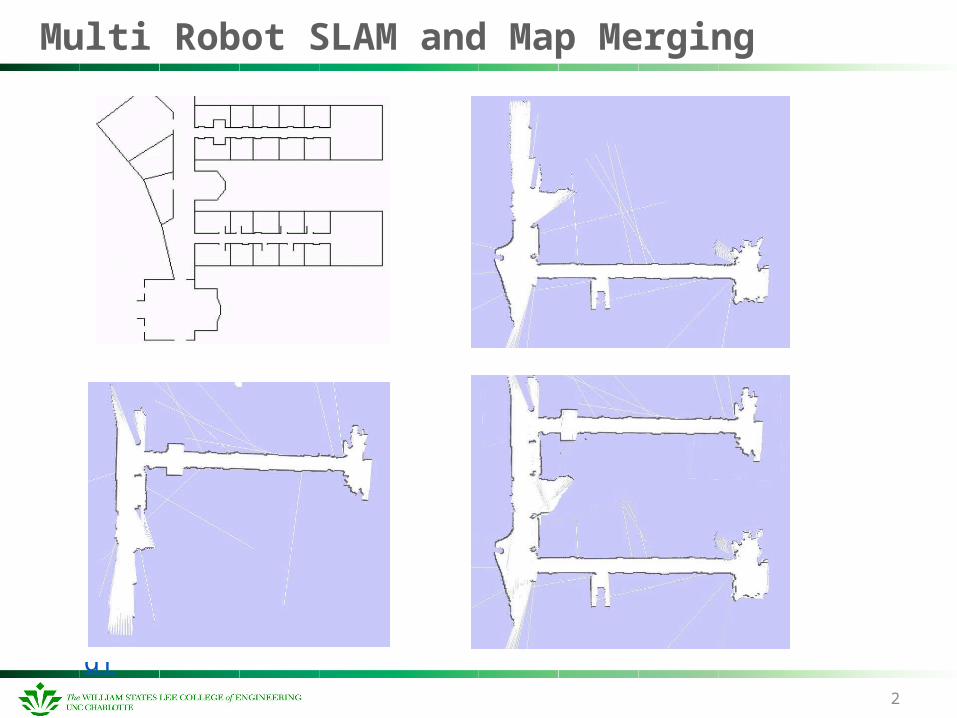
Multi Robot SLAM and Map Merging
Need for Map Merging
Scan Matching SLAM The main aim is to find the most likely global map. Define map m based on the laser scan, pose and time. Take various laser measurements and odometry readings
for different time slots.
Reference http://tv.uvigo.es/uploads/material/Video/2662/P05.pdf
2
SLAM with RFID Technology
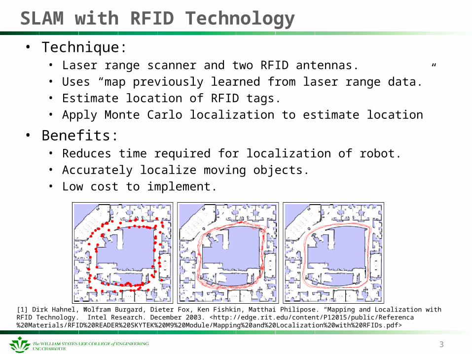
• Technique:• Laser range scanner and two RFID antennas.• Uses “map previously learned from laser range data.” • Estimate location of RFID tags.• Apply Monte Carlo localization to estimate location
• Benefits:• Reduces time required for localization of robot.• Accurately localize moving objects.• Low cost to implement.
3
[1] Dirk Hahnel, Wolfram Burgard, Dieter Fox, Ken Fishkin, Matthai Philipose. “Mapping and Localization with RFID Technology.” Intel Research. December 2003. <http://edge.rit.edu/content/P12015/public/Referenca%20Materials/RFID%20READER%20SKYTEK%20M9%20Module/Mapping%20and%20Localization%20with%20RFIDs.pdf>
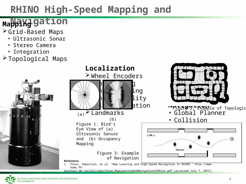
RHINO High-Speed Mapping and Navigation
4
MappingGrid-Based Maps
• Ultrasonic Sonar• Stereo Camera• Integration
Topological Maps
Localization
Wheel EncodersMap MatchingSonar ModelingManeuverabilityWall OrientationLandmarks
Navigation• Global Planner
• Collision Avoidance• Hard Constraints• Soft Constraints
Reference1. Thrun, Sebastian, et al. "Map Learning and High-Speed Navigation in RHINO." http://www-home.fh-konstanz.de/~bittel/robo/thrun_MapLearningAndNavigationInRhino.pdf (accessed July 7, 2012).
(a) (b)Figure 1: Bird’s Eye View of (a) Ultrasonic Sensor and (b) Occupancy Mapping
Figure 3: Example of Navigation
Figure 2: Example of Topological Mapping
Stanley – Stanford University DARPA Challenge
• Probabilistic Terrain Analysis Algorithm (Enabled High Speed Desert Driving).
• 5 LIDAR Units used for 3D Mapping.• Inertial guidance system (3 gyroscopes and 3 accelerometers).• GPS Waypoints.• Color Video Camera.• Output data from the 3D LIDAR was compressed into a 2D
map divided into a grid of 30 x 30 cm cells.• Cells are then designated as either: drivable, obstacle, or
unknown.• Software algorithm compares samples of video deemed to be
“drivable” by the LIDAR map and uses this “knowledge” to determine the “drivable surface in the remainder of the video.
5
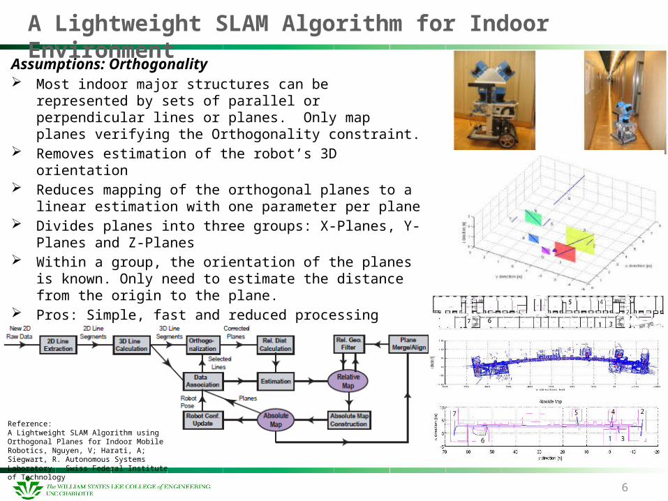
A Lightweight SLAM Algorithm for Indoor Environment
Assumptions: Orthogonality Most indoor major structures can be represented by sets of
parallel or perpendicular lines or planes. Only map planes verifying the Orthogonality constraint.
Removes estimation of the robot’s 3D orientation Reduces mapping of the orthogonal planes to a linear
estimation with one parameter per plane Divides planes into three groups: X-Planes, Y-Planes and Z-
Planes Within a group, the orientation of the planes is known. Only
need to estimate the distance from the origin to the plane. Pros: Simple, fast and reduced processing power Cons: Orthogonality assumption, does not work well in
outdoor environment or with complex surfaces
6
Reference:A Lightweight SLAM Algorithm using Orthogonal Planes for Indoor Mobile Robotics, Nguyen, V; Harati, A; Siegwart, R. Autonomous Systems Laboratory. Swiss Federal Institute of Technology

Slam – Rapid 3D Mapping
SLAM is the problem of building a map of an unknown environment while at the same time navigating the environment, using the unfinished map
3D maps give you an overhead view of a location, like a traditional paper map. 3D maps give you a schematic, angled view of the route ahead of you, as if seen from the air above you.
http://www.youtube.com/watch?v=CNemPTHOKWg&feature=player_embedded
3 Steps to Superior Awareness
http://www.youtube.com/watch?v=s6odzWGqi70&feature=player_embedded
http://www.saabgroup.com/Global/Documents%20and%20Images/Campaigns/Rapid%203D%20Mapping/SanFransisco_small.jpg
http://www.saabgroup.com/Global/Documents%20and%20Images/Campaigns/Rapid%203D%20Mapping/Hoover_Dam_Rapid_3D_Mapping_small.jpg
1. Fly2. Generate3. View
3D Mapping Applications Videos
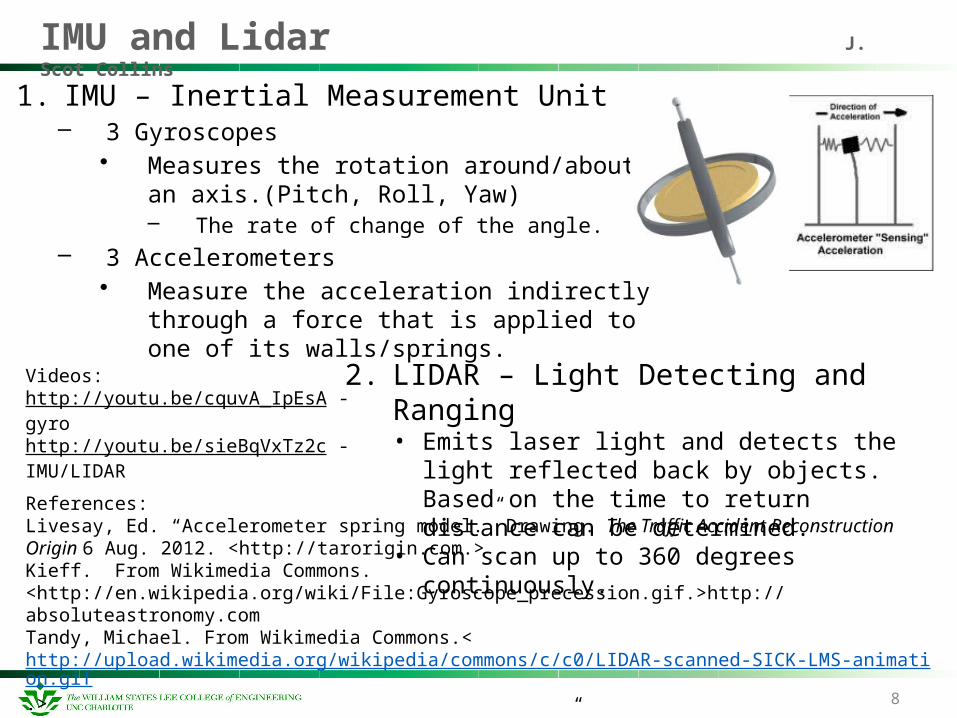
IMU and Lidar J. Scot Collins
1. IMU – Inertial Measurement Unit– 3 Gyroscopes
• Measures the rotation around/about an axis.(Pitch, Roll, Yaw)– The rate of change of the angle.
– 3 Accelerometers• Measure the acceleration indirectly through a
force that is applied to one of its walls/springs.
8
References:Livesay, Ed. “Accelerometer spring model.” Drawing. The Traffic Accident Reconstruction Origin 6 Aug. 2012. <http://tarorigin.com.>Kieff. From Wikimedia Commons. <http://en.wikipedia.org/wiki/File:Gyroscope_precession.gif.>http://absoluteastronomy.comTandy, Michael. From Wikimedia Commons.<http://upload.wikimedia.org/wikipedia/commons/c/c0/LIDAR-scanned-SICK-LMS-animation.gif.>Gadget Gangster. “Accelerometer & Gyro Tutorial.” Instructables. 6 Aug. 2012. <http://www.instructables.com.>
2. LIDAR – Light Detecting and Ranging• Emits laser light and detects the light reflected
back by objects. Based on the time to return distance can be determined.
• Can scan up to 360 degrees continuously.
Videos:http://youtu.be/cquvA_IpEsA - gyrohttp://youtu.be/sieBqVxTz2c - IMU/LIDAR
iRSP SLAM 3D Execution
9
This PowerPoint is about the demonstration of 3D SLAM capability of a robot using iRSP(intelligent Robot Software Platform). The map data for the demonstration is updated from the calculated position of the robot using simulated onboard range sensors.
Simulated robot:• Motor: 2 DC Motors• Sensors:
• 1D range sensor: 8 Sonar sensors• 3D range sensor: Xtion-Pro• Direction sensor: Absolute Compass Sensor
Video: http://www.youtube.com/watch?v=AByETaadky4
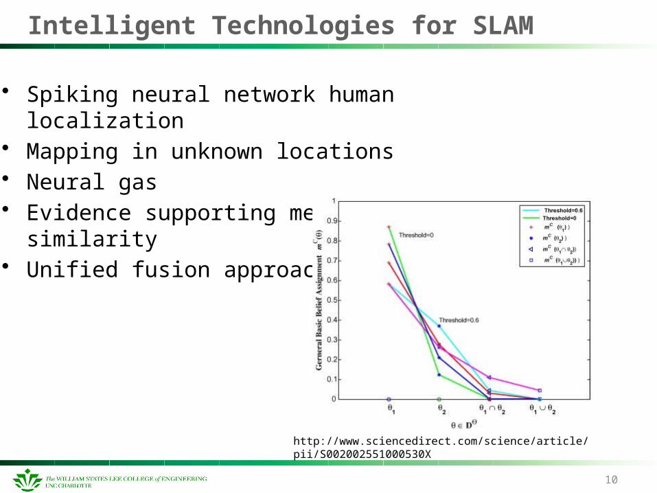
Intelligent Technologies for SLAM
• Spiking neural network human localization• Mapping in unknown locations• Neural gas• Evidence supporting measure of similarity• Unified fusion approach
10
http://www.sciencedirect.com/science/article/pii/S002002551000530X

11
Atlas – mapping of large-scale environments
Algorithm: Dijkstra Shortest Path
Visualization:• Global Optimized Map• Atlas graph
Bosse, Newman, Leonard, et al. International Conference on Robotics and Automation, TBipei, Taiwan, September 2003, pp. 1899-1906
• Starts at a source vertex• Creates a tree to other vertices
• Ordered by distance
Method of Storage:• Local Region SLAM• Map-frame hypotheses
• Juvenile• Mature • Dominant • Retired
Results:
• 101 map-frames• 15 mapped line
segments
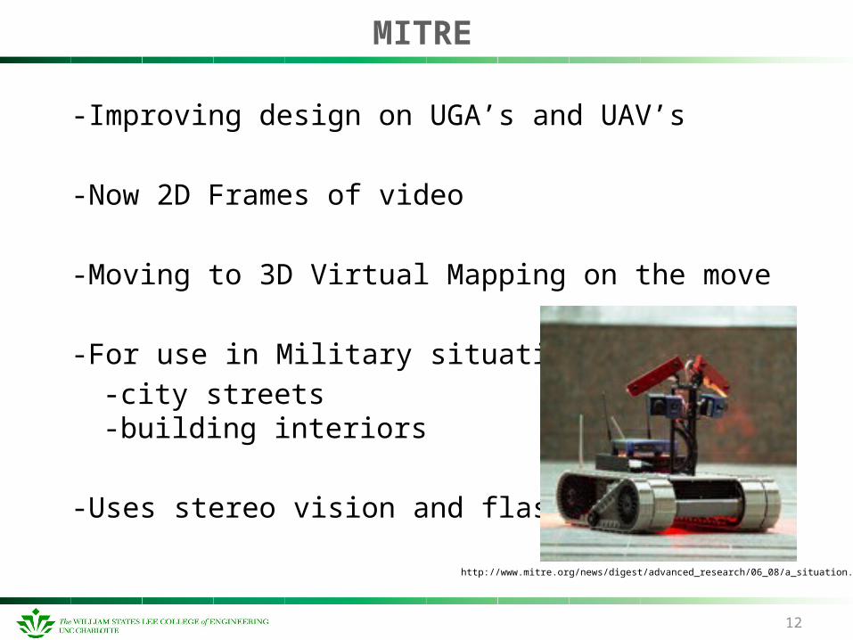
MITRE
-Improving design on UGA’s and UAV’s
-Now 2D Frames of video
-Moving to 3D Virtual Mapping on the move
-For use in Military situations
-city streets-building interiors
-Uses stereo vision and flash LIDAR
12
http://www.mitre.org/news/digest/advanced_research/06_08/a_situation.html
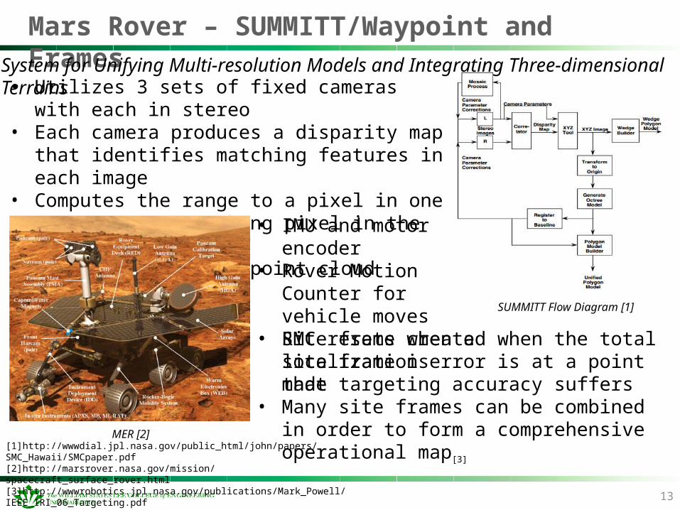
Mars Rover – SUMMITT/Waypoint and Frames
13
[1]http://wwwdial.jpl.nasa.gov/public_html/john/papers/SMC_Hawaii/SMCpaper.pdf[2]http://marsrover.nasa.gov/mission/spacecraft_surface_rover.html[3]http://wwwrobotics.jpl.nasa.gov/publications/Mark_Powell/IEEE_IRI_06_Targeting.pdf
SUMMITT Flow Diagram [1]
• Utilizes 3 sets of fixed cameras with each in stereo• Each camera produces a disparity map that identifies
matching features in each image• Computes the range to a pixel in one image to its
matching pixel in the other image• Used to create XYZ point cloud model[2]
• IMU and motor encoder• Rover Motion Counter for
vehicle moves• RMC resets when a site
frame is made
MER [2]
System for Unifying Multi-resolution Models and Integrating Three-dimensional Terrains
• Site frame created when the total localization error is at a point that targeting accuracy suffers
• Many site frames can be combined in order to form a comprehensive operational map[3]
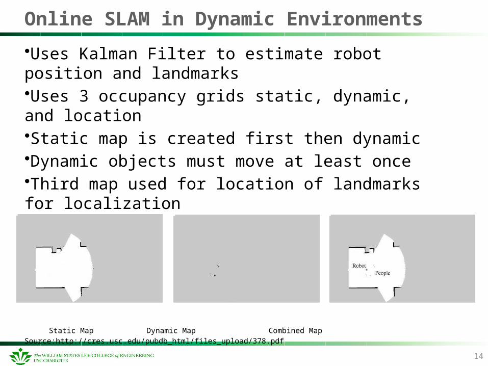
Online SLAM in Dynamic Environments
•Uses Kalman Filter to estimate robot position and landmarks•Uses 3 occupancy grids static, dynamic, and location•Static map is created first then dynamic •Dynamic objects must move at least once•Third map used for location of landmarks for localization
Static Map Dynamic Map Combined Map
Source:http://cres.usc.edu/pubdb_html/files_upload/378.pdf
14
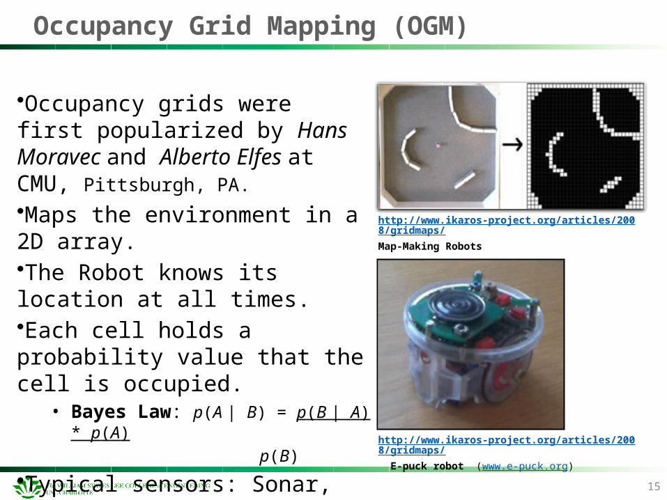
Occupancy Grid Mapping (OGM)
•Occupancy grids were first popularized by Hans Moravec and Alberto Elfes at CMU, Pittsburgh, PA.
•Maps the environment in a 2D array.•The Robot knows its location at all times.•Each cell holds a probability value that the cell is occupied.
• Bayes Law: p(A | B) = p(B | A) * p(A)
p(B)
•Typical sensors: Sonar, Laser, IR, Bump, etc.
http://www.ikaros-project.org/articles/2008/gridmaps/
Map-Making Robots
15
http://www.ikaros-project.org/articles/2008/gridmaps/
E-puck robot (www.e-puck.org)
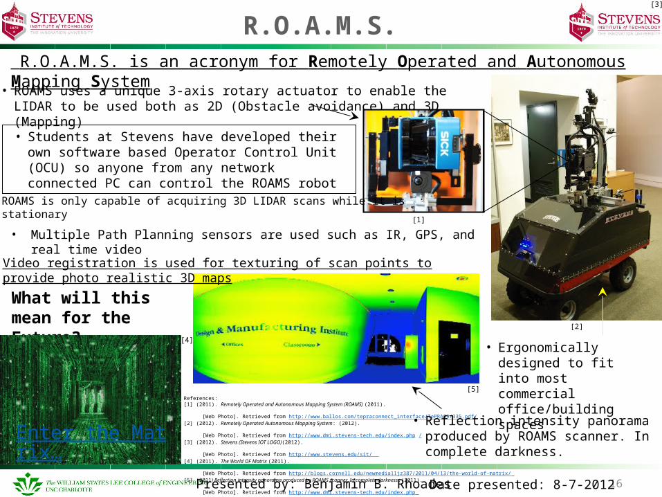
R.O.A.M.S.
16Presented by: Benjamin B. Rhoades Date presented: 8-7-2012
References:[1] (2011). Remotely Operated and Autonomous Mapping System (ROAMS) (2011). [Web Photo]. Retrieved from http://www.ballos.com/tepraconnect_interface/TePRA09/335.pdf/ [2] (2012). Remotely Operated Autonomous Mapping System: (2012). [Web Photo]. Retrieved from http://www.dmi.stevens-tech.edu/index.php /[3] (2012). Stevens (Stevens IOT LOGO)(2012). [Web Photo]. Retrieved from http://www.stevens.edu/sit/ [4] (2011). The World OF Matrix (2011). [Web Photo]. Retrieved from http://blogs.cornell.edu/newmedia11jz387/2011/04/13/the-world-of-matrix/ [5] (2011) Reflection intensity panorama produced by ROAMS scanner. In complete darkness.(2011). [Web Photo]. Retrieved from http://www.dmi.stevens-tech.edu/index.php
R.O.A.M.S. is an acronym for Remotely Operated and Autonomous Mapping System
What will this mean for the Future?...
• Ergonomically designed to fit into most commercial office/building spaces
• ROAMS uses a unique 3-axis rotary actuator to enable the LIDAR to be used both as 2D (Obstacle avoidance) and 3D (Mapping)
[3]
[4]
Enter the Matrix…
[2]
[1]
ROAMS is only capable of acquiring 3D LIDAR scans while it is stationary
• Reflection intensity panorama produced by ROAMS scanner. In complete darkness.
[5]
• Students at Stevens have developed their own software based Operator Control Unit (OCU) so anyone from any network connected PC can control the ROAMS robot
Video registration is used for texturing of scan points to provide photo realistic 3D maps
• Multiple Path Planning sensors are used such as IR, GPS, and real time video
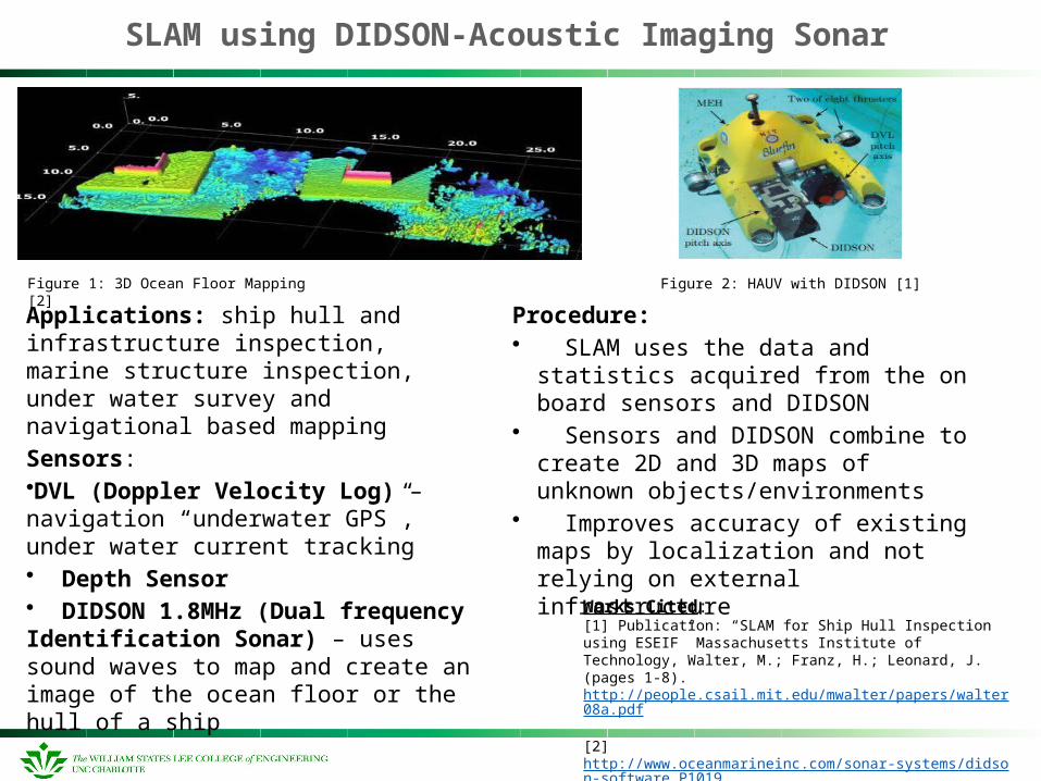
SLAM using DIDSON-Acoustic Imaging Sonar
Applications: ship hull and infrastructure inspection, marine structure inspection, under water survey and navigational based mapping
Sensors:•DVL (Doppler Velocity Log) – navigation “underwater GPS”, under water current tracking• Depth Sensor• DIDSON 1.8MHz (Dual frequency Identification Sonar) – uses sound waves to map and create an image of the ocean floor or the hull of a ship
Figure 1: 3D Ocean Floor Mapping [2]
Works Cited: [1] Publication: “SLAM for Ship Hull Inspection using ESEIF” Massachusetts Institute of Technology, Walter, M.; Franz, H.; Leonard, J. (pages 1-8). http://people.csail.mit.edu/mwalter/papers/walter08a.pdf [2] http://www.oceanmarineinc.com/sonar-systems/didson-software_P1019
Figure 2: HAUV with DIDSON [1]
Procedure:• SLAM uses the data and statistics acquired
from the on board sensors and DIDSON• Sensors and DIDSON combine to create 2D
and 3D maps of unknown objects/environments
• Improves accuracy of existing maps by localization and not relying on external infrastructure
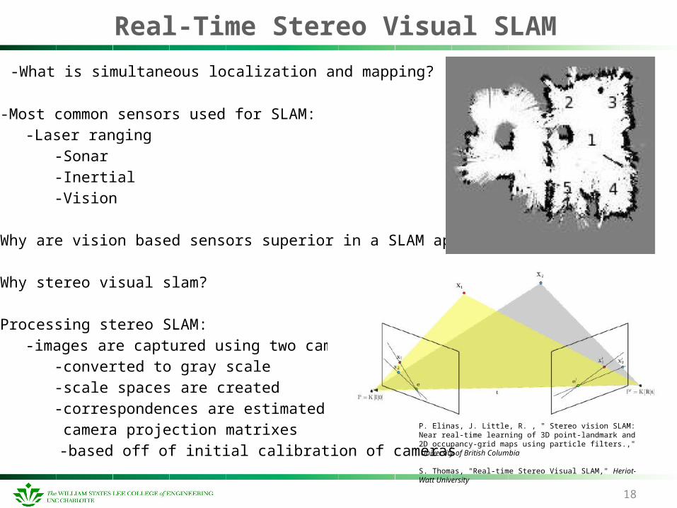
Real-Time Stereo Visual SLAM
-What is simultaneous localization and mapping?
-Most common sensors used for SLAM:
-Laser ranging
-Sonar
-Inertial
-Vision
Why are vision based sensors superior in a SLAM application?
Why stereo visual slam?
Processing stereo SLAM:
-images are captured using two cameras
-converted to gray scale
-scale spaces are created
-correspondences are estimated using
camera projection matrixes
-based off of initial calibration of cameras
18
P. Elinas, J. Little, R. , " Stereo vision SLAM: Near real-time learning of 3D point-landmark and 2D occupancy-grid maps using particle filters.," University of British Columbia
S. Thomas, "Real-time Stereo Visual SLAM," Heriot-Watt University

Mini-SLAM
19
Hardware uses odometry and an omnidirectional camera.
The camera supplies information used by SLAM algorithm. More consistent maps created.
Map estimations done by a linear time SLAM algorithm using graph representation. Scales better due to not estimating landmark
locations Instead, object similarity used to determine
landmark locations. Uses Multilevel Relaxation algorithm to
determine that objects in images are the same.
“Mini-SLAM: Minimalistic Visual SLAM in Large-Scale Environments Based on a New Interpretation of Image Similarity.” Henric Andreasson, Tom Duckett, and Achim Lilienthal. <http://aass.oru.se/~han/papers/icra07andreasson.pdf>.
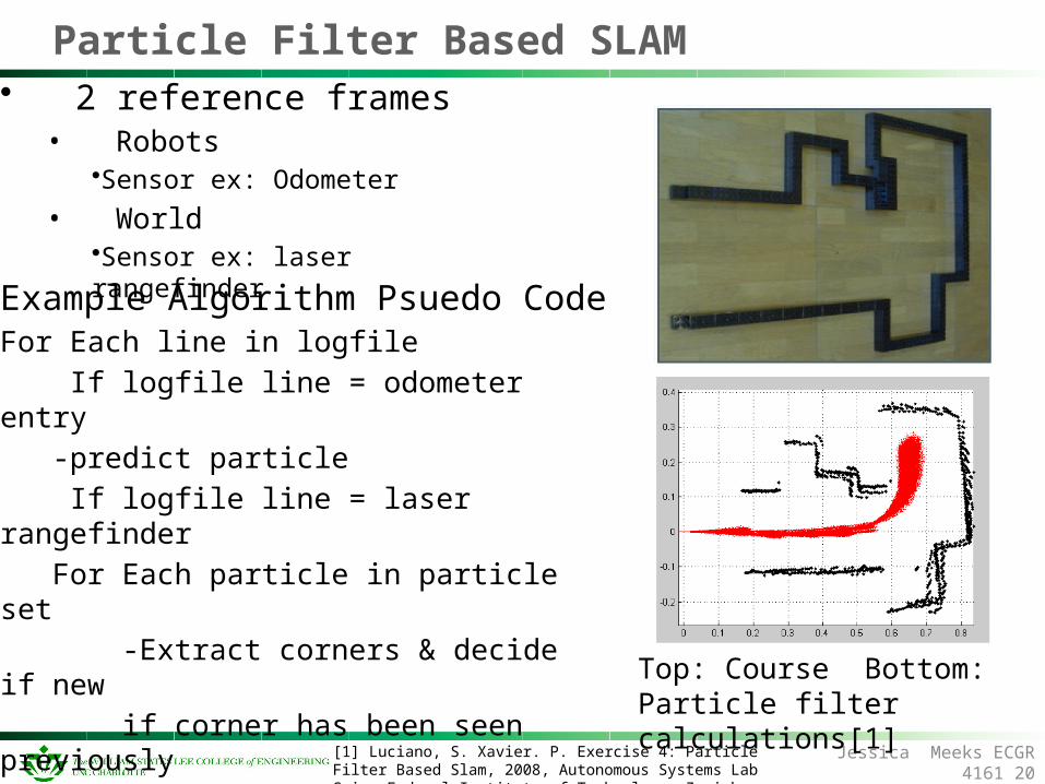
Particle Filter Based SLAM• 2 reference frames
• Robots•Sensor ex: Odometer
• World•Sensor ex: laser rangefinder
Jessica Meeks ECGR 416120
Example Algorithm Psuedo CodeFor Each line in logfile
If logfile line = odometer entry
-predict particle
If logfile line = laser rangefinder
For Each particle in particle set
-Extract corners & decide if new
if corner has been seen previously
compute new weight of corner
else
add new corner to particles[1] Luciano, S. Xavier. P. Exercise 4: Particle Filter Based Slam, 2008, Autonomous Systems Lab Swiss Federal Institute of Technology, Zurich
Top: Course Bottom: Particle filter calculations[1]
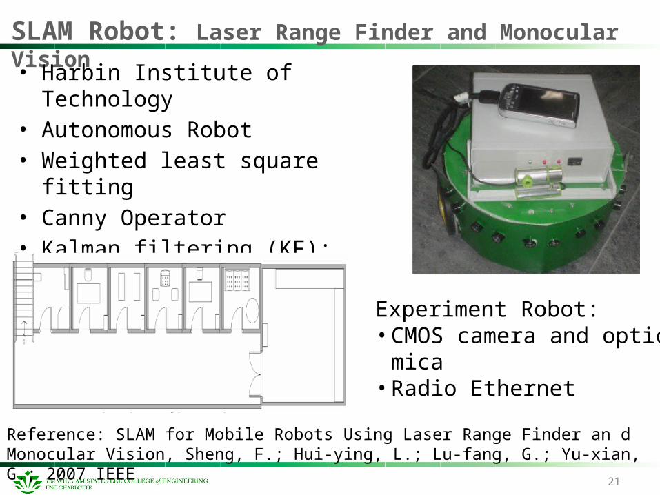
SLAM Robot: Laser Range Finder and Monocular Vision
21
• Harbin Institute of Technology • Autonomous Robot• Weighted least square fitting • Canny Operator • Kalman filtering (KF): localization &
grid map building simultaneously
Reference: SLAM for Mobile Robots Using Laser Range Finder an d Monocular Vision, Sheng, F.; Hui-ying, L.; Lu-fang, G.; Yu-xian, G.; 2007 IEEE
Experiment Robot:• CMOS camera and optic mica• Radio Ethernet