Embed Size (px)
Citation preview
ISSN: 2249-1236 A. S. Alkhader et al.,(2015) Vol.5 Issue.2 Pg:1219--1230 International Journal of Research and Reviews in Pharmacy and Applied sciences Copyright © 2015 ijrrpas.com. All rights reserved
www.ijrrpas.com 1219
ECG Interface Circuit Design for Improving The Quality of ECG Signal
A. S. Alkhader* Biomedical engineer with the Institute of Biomedical Technology at Royal Medical Services Amman, Jordan Aktham A. Alomar, Biomedical engineer with King Hussein Medical Center at Royal Medical Services Amman, Jordan Abdullah S. Althonaibat, Biomedical engineer with Prince Ali Hospital at Royal Medical Services Karak, Jordan Basma S. Hiyari Biomedical engineer with the Institute of Biomedical Technology at Royal Medical Services Amman, Jordan Mohammad A. Alshira'ah, Biomedical engineer with King Hussein Medical Center at at Royal Medical Services Amman, Jordan,
Abstract: Over the years, many circuit designs were developed for detecting the electrical activity of the heart (ECG signal). The main aim was to reduce the noise and improving the efficiency and quality of the signal obtained from the heart. In this paper a suggested design of a single channel ECG circuit is introduced, it shows how to build the ECG circuit step by step, investigates the quality of the signal obtained after adding each stage of the circuit and offers a suggestions and ideas of the best circuit design and the best ICs that can be used to reduce the noises to get the best quality of ECG signal. This design is composed of the usual main parts which are instrumentation amplifier (IA), isolation circuit (iso-amp), band pass filter, and right leg circuit, in addition to a suggested first and second order band pass filter and a notch filter. The advantages of this design are its simplicity and high efficiency which represents in its ability to obtain a good quality signals with minimum noises, as it has many stages of filtration, in addition to its low cost which offers the opportunity to manufacture it in Jordan.
Keywords: Electrocardiography; Band Width; Band Pass Filter; Frequency Domain; Biosignal; ECG Amplifier; Notch Filter.
Introduction
The heart represents the secrete of existence, its importance and complexity inspire researchers and scientists to do their best and offer much efforts in studying it and its electrical activity. The ECG signal is the link between the researchers and the human heart; it is an indication of the heart function, so that, the quality of the signal obtained from the heart is very important to get the right information about the heart functions. In this project, the main aim is to add something in filtration field of the ECG signal and developing the ECG circuit design by adding many stages of filtration in order to obtain the best accurate signal.
An ECG amplifier is a bioelectric amplifier which mostly has a medium gain factor of 1000. Each ECG amplifier contains an instrumentation amplifier (IA), isolation amplifier (iso-amp), band pass filter (BPF), and right leg (RL) drive amplifier[1-3].
ISSN: 2249-1236 A. S. Alkhader et al.,(2015) Vol.5 Issue.2 Pg:1219--1230 International Journal of Research and Reviews in Pharmacy and Applied sciences Copyright © 2015 ijrrpas.com. All rights reserved
www.ijrrpas.com 1220
This paper introduces a suggested circuit design that composed of these standard parts, in addition to a combination of an extra first and second order filtration by using zero phase band pass filter (ZPBPF), and a final stage represented in a notch filter. The bandwidth range of interest is that for ECG monitoring purposes that is about 0.05-40Hz. This circuit is supposed to be for a single-channel ECG detection through an external body surface electrodes, but there are many another biological signals that are produced by different organs in the human body therefore, multi-channel signal recording system with its biopotential electrodes are usually used. These electrodes refer to a leads which represent the distance between two points within the body surface, and they should be placed in a proper way and position to be allowed to obtain different recordings, wherein each lead transfer different information about that targeted organ. So, number of electrodes used depends on the required and desired ECG reading.
FREQUENCY DOMAIN OF THE ECG SIGNAL
ECG bandwidth contains an valuable information about frequency, therefore, the frequency-domain is an important issue that is needed to determine the linear system preprocessing parameters. [0.5-3Hz] is the heart rate frequency for heart rate of 30-180 bpm [2]. Many issues play a role in identifying the highest frequency like age, sex, and the overall state of health of the patient, about 125Hz is considered the typical value [3-5].
The required bandwidths for a different applications can be summarized as [7]: [0.05-100Hz] for 12-lead ECG clinical applications, [0.50-50Hz] for monitoring application at Intensive Care Unit (ICU), while for Cardio tachometer and heart rate detector, a band pass filter with 17Hz centered frequency is used with also a Q-wave selectivity to ensure passing only the QRS-wave frequencies while blocking non-QRS waves like (P and T waves) and other noises. And up to 500Hz bandwidth for late potential measurement which are small higher frequencies that follow QRS complex of the ECG signal.
Sources Of Noises
There are many sources of noise which may affect the ECG signal, the sources of artifacts can be classified into two kinds, artificial or biological [4-7]. Artificial artifact like power line interface, electrostatic potentials, impulse noise and noises of the other electronic devices while biological artifacts are motion or muscle artifacts (EMG signal).
DESIGN OF THE ECG CIRCUIT
Instrumentation Amplifier (First Stage)
As mentioned before, the design consists of many stages, the first step is building the instrumentation amplifier (IA) circuit. One of the best ICs for building this circuit is AD620 as it has many features that make it suitable for such application, like ease of use, low noise, excellent DC performance and AC specifications, and low cost.
AD620 is considered a high accuracy analog device instrumentation amplifier that has higher performance than three op-amp IA design.
ISSN: 2249-1236 A. S. Alkhader et al.,(2015) Vol.5 Issue.2 Pg:1219--1230 International Journal of Research and Reviews in Pharmacy and Applied sciences Copyright © 2015 ijrrpas.com. All rights reserved
www.ijrrpas.com 1221
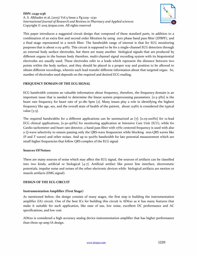
The electrical characteristics of the AD620 can be summarized in low input bias, a gain range from 1 to 1000 with a need for only one external resistor for setting this gain range, wide power supply range from ±2.3V to ±18V and a low power of 1.3 mA of maximum supply current making it suited for portable and battery powered applications. Furthermore, its excellent AC specifications with a120 KHz bandwidth and a gain of 100. All these specifications make this IC very well suited for many circuits and medical applications such as ECG.
Figure 1: AD620 As shown in figure 1, there are two analog input pins for AD620, pin 2 for the negative electrode and pin 3 for the positive electrode. the following table represents the main three bipolar limb leads and their proper electrode connections.
Lead Positive (+) electrode
Negative (-) electrode
I Left arm Right Arm
II Left leg Right Arm
III Left leg Left Arm
Table 1: Electrode connection for three bipolar limb leads
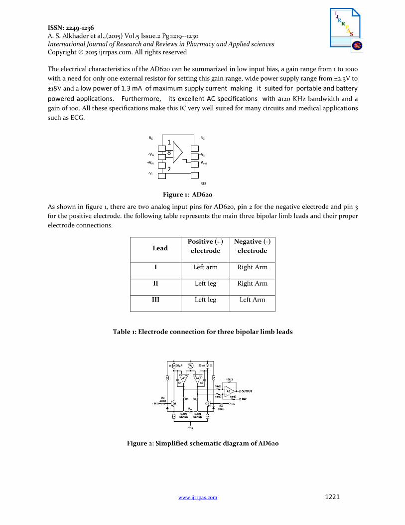
Figure 2: Simplified schematic diagram of AD620
1 8
2
RG
-VIN
RG
Vout +VIN
-VS
REF
+VS
ISSN: 2249-1236 A. S. Alkhader et al.,(2015) Vol.5 Issue.2 Pg:1219--1230 International Journal of Research and Reviews in Pharmacy and Applied sciences Copyright © 2015 ijrrpas.com. All rights reserved
www.ijrrpas.com 1222
Based on the simplified schematic diagram of the AD620 shown in figure (2), and the amplification goal of this stage, the internal gain resistors R1 and R2 (figure 2), are fixed to an absolute value of 24.7KΩ to allow the accurate control of the gain by a single external resistor (RG in figure 2), (R3 in the circuit in figure 3).
So, the differential gain can be expressed by:
G = ( R1 + R2 )/ RG + 1 (1)
The gain is then:
G = 49.4KΩ /RG +1
For accuracy, RG (R3 in the circuit) was chosen to be 2KΩ. 1% tolerance, So that, the output gain of the IA will be 25.7. The output of the AD620 was eliminated to be about 2V below the supply voltages. To prevent output saturation the gain of the IA was set to a low gain range (less than 33) [9], [11].
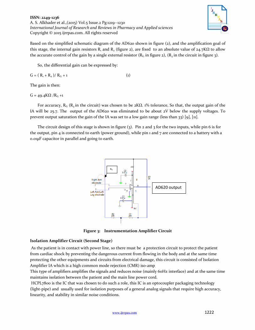
The circuit design of this stage is shown in figure (3). Pin 2 and 3 for the two inputs, while pin 6 is for the output, pin 4 is connected to earth (power ground), while pin 1 and 7 are connected to a battery with a 0.01µF capacitor in parallel and going to earth.
Figure 3: Instrumentation Amplifier Circuit
Isolation Amplifier Circuit (Second Stage)
As the patient is in contact with power line, so there must be a protection circuit to protect the patient from cardiac shock by preventing the dangerous current from flowing in the body and at the same time protecting the other equipments and circuits from electrical damage, this circuit is consisted of Isolation Amplifier IA which is a high common mode rejection (CMR) iso-amp.
This type of amplifiers amplifies the signals and reduces noise (mainly 60Hz interface) and at the same time maintains isolation between the patient and the main line power cord. HCPL7800 is the IC that was chosen to do such a role, this IC is an optocoupler packaging technology (light-pipe) and usually used for isolation purposes of a general analog signals that require high accuracy, linearity, and stability in similar noise conditions.
AD620 output
RG
ISSN: 2249-1236 A. S. Alkhader et al.,(2015) Vol.5 Issue.2 Pg:1219--1230 International Journal of Research and Reviews in Pharmacy and Applied sciences Copyright © 2015 ijrrpas.com. All rights reserved
www.ijrrpas.com 1223
Optocoupler: is a combination of a light source and light detector together in a single component which provides high voltage isolation by converting the electrical signal to light energy by light emitting diode (LED), then the optical signal is converted back to electrical signal by photodetector.
Figure 4: HCPL7800
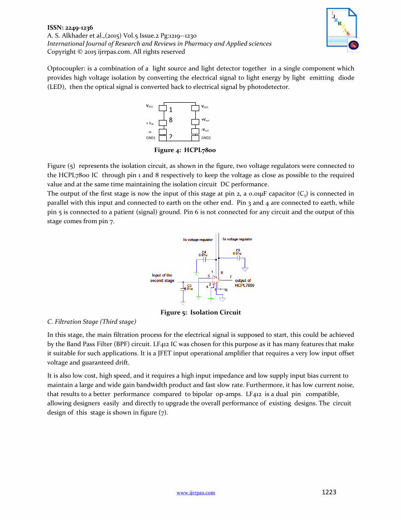
Figure (5) represents the isolation circuit, as shown in the figure, two voltage regulators were connected to the HCPL7800 IC through pin 1 and 8 respectively to keep the voltage as close as possible to the required value and at the same time maintaining the isolation circuit DC performance. The output of the first stage is now the input of this stage at pin 2, a 0.01µF capacitor (C3) is connected in parallel with this input and connected to earth on the other end. Pin 3 and 4 are connected to earth, while pin 5 is connected to a patient (signal) ground. Pin 6 is not connected for any circuit and the output of this stage comes from pin 7.
Figure 5: Isolation Circuit
C. Filtration Stage (Third stage)
In this stage, the main filtration process for the electrical signal is supposed to start, this could be achieved by the Band Pass Filter (BPF) circuit. LF412 IC was chosen for this purpose as it has many features that make it suitable for such applications. It is a JFET input operational amplifier that requires a very low input offset voltage and guaranteed drift.
It is also low cost, high speed, and it requires a high input impedance and low supply input bias current to maintain a large and wide gain bandwidth product and fast slow rate. Furthermore, it has low current noise, that results to a better performance compared to bipolar op-amps. LF412 is a dual pin compatible, allowing designers easily and directly to upgrade the overall performance of existing designs. The circuit design of this stage is shown in figure (7).
1 8
2
VDD2
+ VIN
VDD1
-Vout -VIN GND1 GND2
+Vout
ISSN: 2249-1236 A. S. Alkhader et al.,(2015) Vol.5 Issue.2 Pg:1219--1230 International Journal of Research and Reviews in Pharmacy and Applied sciences Copyright © 2015 ijrrpas.com. All rights reserved
www.ijrrpas.com 1224
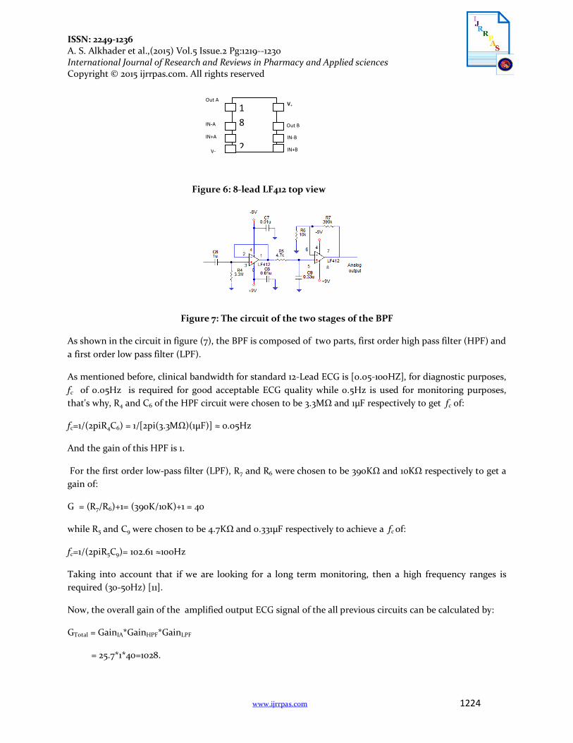
Figure 6: 8-lead LF412 top view
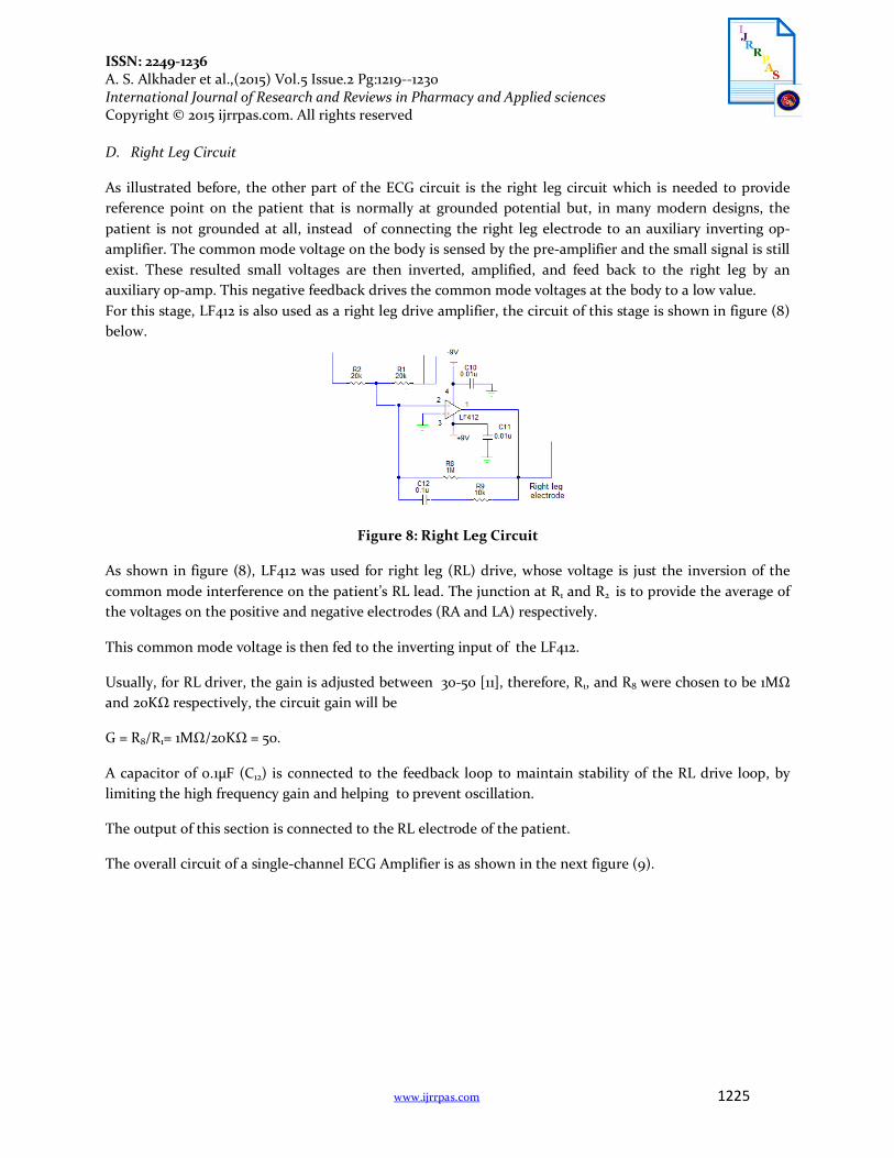
Figure 7: The circuit of the two stages of the BPF
As shown in the circuit in figure (7), the BPF is composed of two parts, first order high pass filter (HPF) and a first order low pass filter (LPF).
As mentioned before, clinical bandwidth for standard 12-Lead ECG is [0.05-100HZ], for diagnostic purposes, fc of 0.05Hz is required for good acceptable ECG quality while 0.5Hz is used for monitoring purposes, that's why, R4 and C6 of the HPF circuit were chosen to be 3.3MΩ and 1µF respectively to get fc of:
fc=1/(2piR4C6) = 1/[2pi(3.3MΩ)(1µF)] ≈ 0.05Hz
And the gain of this HPF is 1.
For the first order low-pass filter (LPF), R7 and R6 were chosen to be 390KΩ and 10KΩ respectively to get a gain of:
G = (R7/R6)+1= (390K/10K)+1 = 40
while R5 and C9 were chosen to be 4.7KΩ and 0.331µF respectively to achieve a fc of:
fc=1/(2piR5C9)= 102.61 ≈100Hz
Taking into account that if we are looking for a long term monitoring, then a high frequency ranges is required (30-50Hz) [11].
Now, the overall gain of the amplified output ECG signal of the all previous circuits can be calculated by:
GTotal = GainIA*GainHPF*GainLPF
= 25.7*1*40=1028.
1 8
2
V+
IN-A
Out A
IN-B IN+A
V- IN+B
Out B
ISSN: 2249-1236 A. S. Alkhader et al.,(2015) Vol.5 Issue.2 Pg:1219--1230 International Journal of Research and Reviews in Pharmacy and Applied sciences Copyright © 2015 ijrrpas.com. All rights reserved
www.ijrrpas.com 1225
D. Right Leg Circuit
As illustrated before, the other part of the ECG circuit is the right leg circuit which is needed to provide reference point on the patient that is normally at grounded potential but, in many modern designs, the patient is not grounded at all, instead of connecting the right leg electrode to an auxiliary inverting op-amplifier. The common mode voltage on the body is sensed by the pre-amplifier and the small signal is still exist. These resulted small voltages are then inverted, amplified, and feed back to the right leg by an auxiliary op-amp. This negative feedback drives the common mode voltages at the body to a low value. For this stage, LF412 is also used as a right leg drive amplifier, the circuit of this stage is shown in figure (8) below.
Figure 8: Right Leg Circuit
As shown in figure (8), LF412 was used for right leg (RL) drive, whose voltage is just the inversion of the common mode interference on the patient’s RL lead. The junction at R1 and R2 is to provide the average of the voltages on the positive and negative electrodes (RA and LA) respectively.
This common mode voltage is then fed to the inverting input of the LF412.
Usually, for RL driver, the gain is adjusted between 30-50 [11], therefore, R1, and R8 were chosen to be 1MΩ and 20KΩ respectively, the circuit gain will be
G = R8/R1= 1MΩ/20KΩ = 50.
A capacitor of 0.1µF (C12) is connected to the feedback loop to maintain stability of the RL drive loop, by limiting the high frequency gain and helping to prevent oscillation.
The output of this section is connected to the RL electrode of the patient.
The overall circuit of a single-channel ECG Amplifier is as shown in the next figure (9).
ISSN: 2249-1236 A. S. Alkhader et al.,(2015) Vol.5 Issue.2 Pg:1219--1230 International Journal of Research and Reviews in Pharmacy and Applied sciences Copyright © 2015 ijrrpas.com. All rights reserved
www.ijrrpas.com 1226
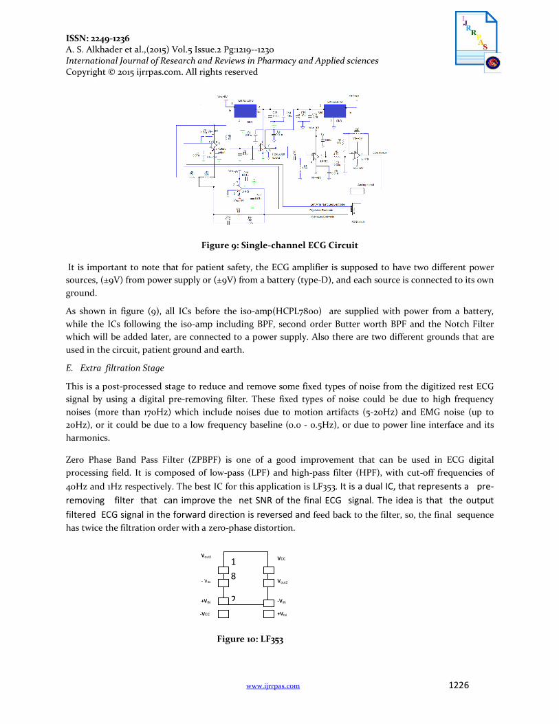
Figure 9: Single-channel ECG Circuit
It is important to note that for patient safety, the ECG amplifier is supposed to have two different power sources, (±9V) from power supply or (±9V) from a battery (type-D), and each source is connected to its own ground.
As shown in figure (9), all ICs before the iso-amp(HCPL7800) are supplied with power from a battery, while the ICs following the iso-amp including BPF, second order Butter worth BPF and the Notch Filter which will be added later, are connected to a power supply. Also there are two different grounds that are used in the circuit, patient ground and earth.
E. Extra filtration Stage
This is a post-processed stage to reduce and remove some fixed types of noise from the digitized rest ECG signal by using a digital pre-removing filter. These fixed types of noise could be due to high frequency noises (more than 170Hz) which include noises due to motion artifacts (5-20Hz) and EMG noise (up to 20Hz), or it could be due to a low frequency baseline (0.0 - 0.5Hz), or due to power line interface and its harmonics.
Zero Phase Band Pass Filter (ZPBPF) is one of a good improvement that can be used in ECG digital processing field. It is composed of low-pass (LPF) and high-pass filter (HPF), with cut-off frequencies of 40Hz and 1Hz respectively. The best IC for this application is LF353. It is a dual IC, that represents a pre-removing filter that can improve the net SNR of the final ECG signal. The idea is that the output filtered ECG signal in the forward direction is reversed and feed back to the filter, so, the final sequence has twice the filtration order with a zero-phase distortion.
Figure 10: LF353
1 8
2
Vcc
- VIN
Vout1
-VIN +VIN
-Vcc +VIN
Vout2
ISSN: 2249-1236 A. S. Alkhader et al.,(2015) Vol.5 Issue.2 Pg:1219--1230 International Journal of Research and Reviews in Pharmacy and Applied sciences Copyright © 2015 ijrrpas.com. All rights reserved
www.ijrrpas.com 1227
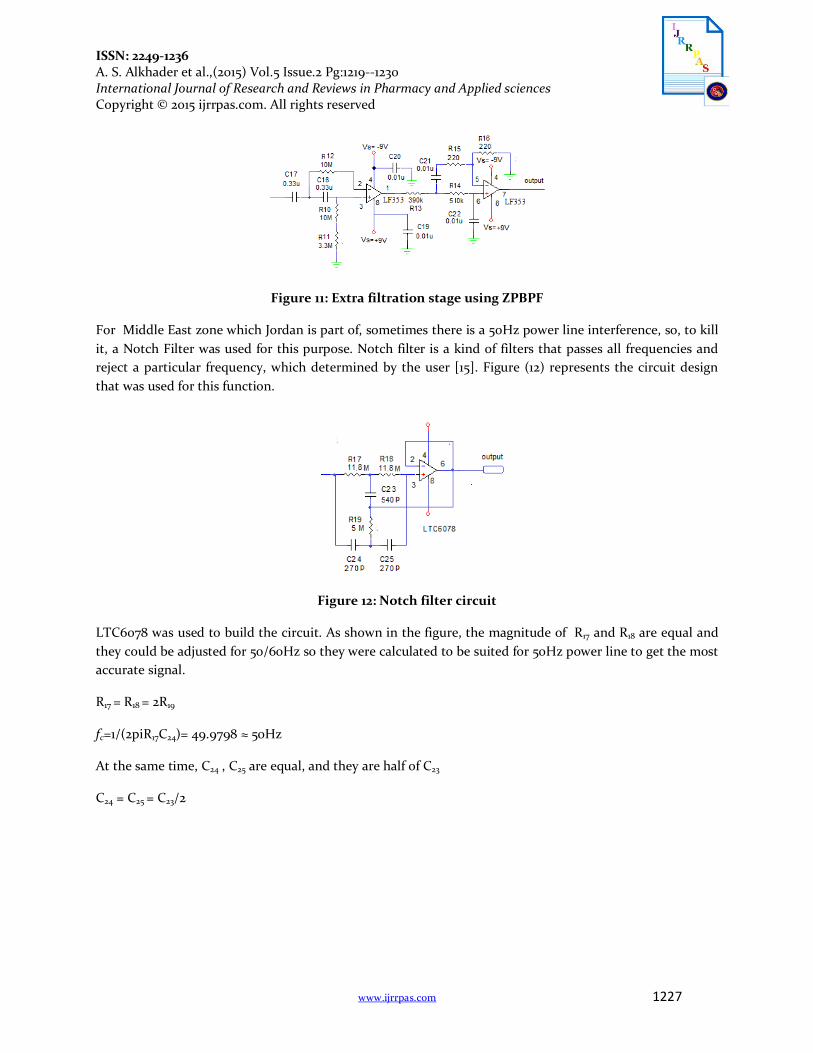
Figure 11: Extra filtration stage using ZPBPF
For Middle East zone which Jordan is part of, sometimes there is a 50Hz power line interference, so, to kill it, a Notch Filter was used for this purpose. Notch filter is a kind of filters that passes all frequencies and reject a particular frequency, which determined by the user [15]. Figure (12) represents the circuit design that was used for this function.
Figure 12: Notch filter circuit
LTC6078 was used to build the circuit. As shown in the figure, the magnitude of R17 and R18 are equal and they could be adjusted for 50/60Hz so they were calculated to be suited for 50Hz power line to get the most accurate signal.
R17 = R18 = 2R19
fc=1/(2piR17C24)= 49.9798 ≈ 50Hz
At the same time, C24 , C25 are equal, and they are half of C23
C24 = C25 = C23/2
ISSN: 2249-1236 A. S. Alkhader et al.,(2015) Vol.5 Issue.2 Pg:1219--1230 International Journal of Research and Reviews in Pharmacy and Applied sciences Copyright © 2015 ijrrpas.com. All rights reserved
www.ijrrpas.com 1228
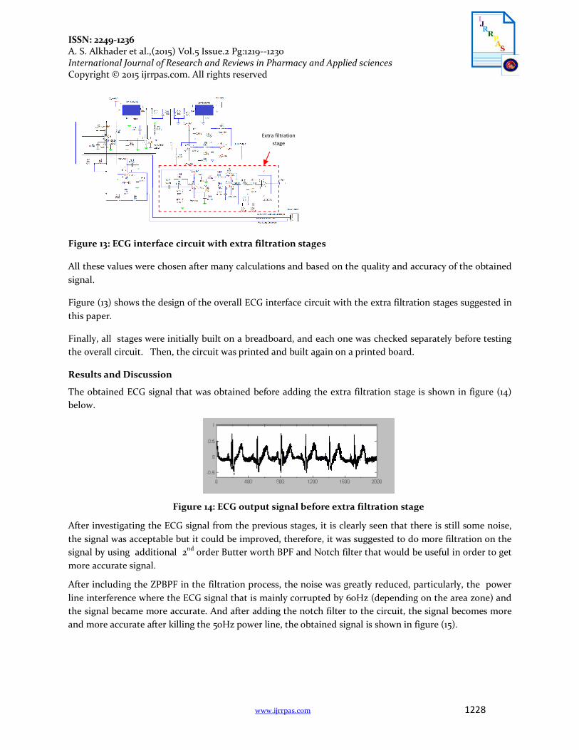
Figure 13: ECG interface circuit with extra filtration stages
All these values were chosen after many calculations and based on the quality and accuracy of the obtained signal.
Figure (13) shows the design of the overall ECG interface circuit with the extra filtration stages suggested in this paper.
Finally, all stages were initially built on a breadboard, and each one was checked separately before testing the overall circuit. Then, the circuit was printed and built again on a printed board.
Results and Discussion
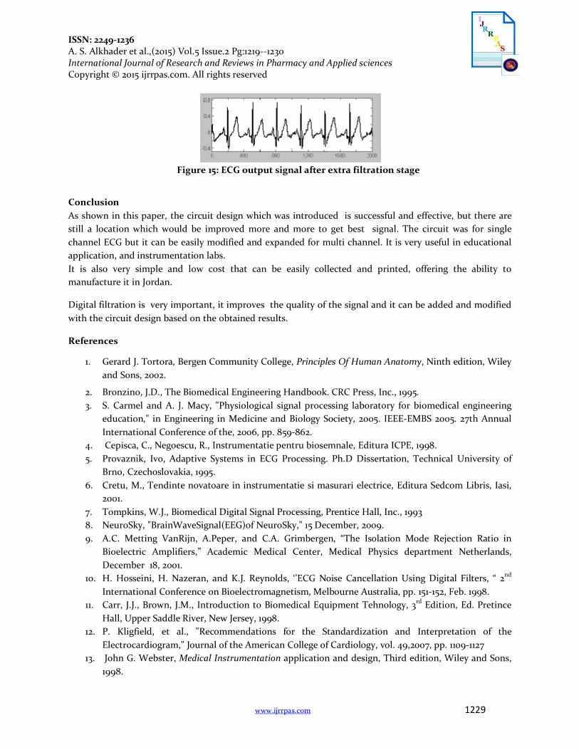
The obtained ECG signal that was obtained before adding the extra filtration stage is shown in figure (14) below.
Figure 14: ECG output signal before extra filtration stage
After investigating the ECG signal from the previous stages, it is clearly seen that there is still some noise, the signal was acceptable but it could be improved, therefore, it was suggested to do more filtration on the signal by using additional 2nd order Butter worth BPF and Notch filter that would be useful in order to get more accurate signal.
After including the ZPBPF in the filtration process, the noise was greatly reduced, particularly, the power line interference where the ECG signal that is mainly corrupted by 60Hz (depending on the area zone) and the signal became more accurate. And after adding the notch filter to the circuit, the signal becomes more and more accurate after killing the 50Hz power line, the obtained signal is shown in figure (15).
Extra filtration stage
ISSN: 2249-1236 A. S. Alkhader et al.,(2015) Vol.5 Issue.2 Pg:1219--1230 International Journal of Research and Reviews in Pharmacy and Applied sciences Copyright © 2015 ijrrpas.com. All rights reserved
www.ijrrpas.com 1229
Figure 15: ECG output signal after extra filtration stage
Conclusion As shown in this paper, the circuit design which was introduced is successful and effective, but there are still a location which would be improved more and more to get best signal. The circuit was for single channel ECG but it can be easily modified and expanded for multi channel. It is very useful in educational application, and instrumentation labs. It is also very simple and low cost that can be easily collected and printed, offering the ability to manufacture it in Jordan.
Digital filtration is very important, it improves the quality of the signal and it can be added and modified with the circuit design based on the obtained results.
References
1. Gerard J. Tortora, Bergen Community College, Principles Of Human Anatomy, Ninth edition, Wiley and Sons, 2002.
2. Bronzino, J.D., The Biomedical Engineering Handbook. CRC Press, Inc., 1995. 3. S. Carmel and A. J. Macy, "Physiological signal processing laboratory for biomedical engineering
education," in Engineering in Medicine and Biology Society, 2005. IEEE-EMBS 2005. 27th Annual International Conference of the, 2006, pp. 859-862.
4. Cepisca, C., Negoescu, R., Instrumentatie pentru biosemnale, Editura ICPE, 1998. 5. Provaznik, Ivo, Adaptive Systems in ECG Processing. Ph.D Dissertation, Technical University of
Brno, Czechoslovakia, 1995. 6. Cretu, M., Tendinte novatoare in instrumentatie si masurari electrice, Editura Sedcom Libris, Iasi,
2001. 7. Tompkins, W.J., Biomedical Digital Signal Processing, Prentice Hall, Inc., 1993 8. NeuroSky, "BrainWaveSignal(EEG)of NeuroSky," 15 December, 2009. 9. A.C. Metting VanRijn, A.Peper, and C.A. Grimbergen, “The Isolation Mode Rejection Ratio in
Bioelectric Amplifiers,” Academic Medical Center, Medical Physics department Netherlands, December 18, 2001.
10. H. Hosseini, H. Nazeran, and K.J. Reynolds, ‘’ECG Noise Cancellation Using Digital Filters, “ 2nd International Conference on Bioelectromagnetism, Melbourne Australia, pp. 151-152, Feb. 1998.
11. Carr, J.J., Brown, J.M., Introduction to Biomedical Equipment Tehnology, 3rd Edition, Ed. Pretince Hall, Upper Saddle River, New Jersey, 1998.
12. P. Kligfield, et al., "Recommendations for the Standardization and Interpretation of the Electrocardiogram," Journal of the American College of Cardiology, vol. 49,2007, pp. 1109-1127
13. John G. Webster, Medical Instrumentation application and design, Third edition, Wiley and Sons, 1998.

ISSN: 2249-1236 A. S. Alkhader et al.,(2015) Vol.5 Issue.2 Pg:1219--1230 International Journal of Research and Reviews in Pharmacy and Applied sciences Copyright © 2015 ijrrpas.com. All rights reserved
www.ijrrpas.com 1230
14. Geddes, 1, A. and L. E. Baker, Principles of Applied Biomedical Instrumentation, Third edition, New York, Wiley, 1989.
15. C.-M. Chang, et al., "Voltage-mode notch, lowpass and bandpass filter using current-feedback amplifiers," Electronics Letters, vol. 30,1994, pp. 2022-2023.
16. M. Joshi,S Patel and Dr. L Hmurcik, "Improvements in Electrocardiography Smoothening and Amplification." University of Bridgeport, 2008.


![RF Circuit Design - [Ch4-1] Microwave Transistor Amplifier](https://img.pdfslide.us/doc/110x75/55cc6094bb61eb9d338b474f/rf-circuit-design-ch4-1-microwave-transistor-amplifier.jpg)