Embed Size (px)
Citation preview
GE.18-01430(E)
Economic Commission for Europe
Inland Transport Committee
World Forum for Harmonization of Vehicle Regulations
Working Party on Lighting and Light-Signalling
Seventy-ninth session
Geneva, 24-27 April 2018
Item 4 of the provisional agenda
Simplification of lighting and light-signalling Regulations
Draft new UN Regulation on uniform provisions concerning the approval of retro-reflective devices and markings for power-driven vehicles and their trailers
Submitted by the Informal Working Group on Simplification of
Lighting and Light-Signalling Regulations (IWG SLR)*
The proposal for a new UN Regulation on Retro-Reflective Devices and markings
(RRD) reproduced below was prepared by the IWG SLR as a result of the discussions
within the informal group. Some text is shown in square brackets to indicate that
consideration and a decision are required.
* In accordance with the programme of work of the Inland Transport Committee for 2014–2018
(ECE/TRANS/240, para. 105 and ECE/TRANS/2014/26, cluster 02.4), the World Forum will
develop, harmonize and update UN Regulations in order to enhance the performance of vehicles. The
present document is submitted in conformity with that mandate.
United Nations ECE/TRANS/WP.29/GRE/2018/4
Economic and Social Council Distr.: General
1 February 2018
Original: English
ECE/TRANS/WP.29/GRE/2018/4
2
I. Proposal
Draft new UN Regulation on uniform provisions concerning the approval of retro-reflective devices and markings for power-driven vehicles and their trailers
Contents Page
1. Scope .............................................................................................................................................. 4
2. Definitions ........................................................................................................................................ 4
3. Administrative Provisions ................................................................................................................ 7
4. General Technical Requirements ..................................................................................................... 14
5. Specific Technical Requirements ..................................................................................................... 16
Annexes
1 Communication ................................................................................................................................ 40
2 Minimum requirements for conformity of production control procedures ....................................... 42
3 Minimum requirements for sampling by an inspector ...................................................................... 44
4 Photometric measurements of retro-reflective devices and marking materials ................................ 46
5 Specifications of shape and dimensions ........................................................................................... 54
6 Resistance to heat ............................................................................................................................. 63
7 Resistance to water penetration for retro-reflective devices and Advance warning triangles .......... 64
8 Alternative test procedures of resistance to water penetration for retro-reflective devices
of the Classes IB and IIIB ............................................................................................................... 66
9 Resistance to fuels ............................................................................................................................ 68
10 Resistance to lubricating oils ............................................................................................................ 69
11 Resistance to corrosion (ISO Standard 3768) .................................................................................. 70
12 Resistance of the accessible rear face of mirror-backed retro-reflective devices ............................. 71
13 Resistance to weathering .................................................................................................................. 72
14 Stability of photometric properties ................................................................................................... 74
15 Resistance to cleaning in the case of a sample unit of retro-reflective marking devices .................. 75
16 Bonding strength .............................................................................................................................. 76
17 Flexing - Retro-reflecting Markings ................................................................................................. 77
18 Resistance to impact ......................................................................................................................... 78
19 Rigidity of plates .............................................................................................................................. 79
20 Further test procedure for Advance Warning Triangles of Type 1 and 2 ........................................ 80
21 Colour-fastness of retro-reflective devices of the Classes IA, IB, IIIA, IIIB and IVA .................... 83
ECE/TRANS/WP.29/GRE/2018/4
3
22 Colour fastness to artificial light – Xenon Arc Test ......................................................................... 84
23 Description of the measurement geometry for measurement of the colour
and the luminance factor of fluorescent retro-reflective materials ................................................... 90
24 Examples of arrangement of approval marks ................................................................................... 91
ECE/TRANS/WP.29/GRE/2018/4
4
Introduction
This UN Regulation combines the provisions of individual Regulations Nos. 3, 27,
69, 70 and 104 into a single Regulation, and is the outcome of the World Forum for
Harmonization of Vehicle Regulations (WP.29) decision to simplify the lighting and light-
signalling Regulations based on the initial proposal by the European Union and Japan.
The objective of this UN Regulation is to increase the clarity, to consolidate and
streamline the complexity of requirements in Regulations Nos. 3, 27, 69, 70 and 104 and to
prepare for the future transition to performance based requirements, by reducing the
number of Regulations through an editorial exercise without changing any of the detailed
technical requirements already in force up to the date of entry into force of this UN
Regulation.
Although this UN Regulation departs from the traditional approach of having a
separate Regulation for each retro-reflective device, by combining all retro-reflectors retro-
reflective marking plates, retro-reflective markings and advance warning triangles into a
single Regulation, this simplified UN Regulation contains all provisions and operates
according to the existing structure of series of amendments, their transitional provisions and
supplements. The transitional provisions associated with a new series of amendments to
this UN Regulation will be identified for each device as applicable, this also includes a list
of devices and their applicable change indexes relating to the series of amendments.
It is expected that all Contracting Parties to the 1958 Agreement will adopt this UN
Regulation and will provide detailed explanation in case they are not in a position to adopt
particular retro-reflective devices. These decisions will be registered in
ECE/TRANS/WP.29/343 that records the status of the annexed UN Regulations and of the
amendments.
Regarding the requirements for approval markings, this UN Regulation includes the
requirements for the use of the "Unique Identifier" and is conditional upon access to a
secure internet database established by UNECE (in accordance with Schedule 5 of the 1958
Agreement) where all type approval documentation is held. When the “Unique Identifier” is
used there is no requirement for retro-reflective devices to carry the conventional type
approval markings (E-mark). If it is technically not possible to use the "Unique Identifier"
(e.g. if the access to the UN internet database cannot be secured or the UN secure internet
database is not operative) the use of conventional type approval markings is required until
the use of the "Unique Identifier" is enabled.
1. Scope
This UN Regulation applies to retro-reflective devices as:
Retro-reflectors of the Classes IA, IB, IIIA, IIIB and IVA
Retro-reflective Markings of the Classes C, D, E and F
Retro-reflective Marking Plates for Heavy and Long Vehicles of the Classes
1, 2, 3, 4 and 5
Retro-reflective Marking Plates for Slow Moving Vehicles of the Classes 1
and 2
Advance Warning Triangles of Type 1 and 2
2. Definitions
For the purpose of this UN Regulation:
ECE/TRANS/WP.29/GRE/2018/4
5
2.1. All the definitions given in the latest series of amendments to UN Regulation
No. 48 in force at the time of application for type approval shall apply, unless
otherwise specified.
2.1.1. "Retro-reflective devices of different types” means retro-reflective devices, as
retro-reflectors or retro-reflective materials or marking plates or advance
warning triangles of different types, which differ in such essential respects as:
(a) the trade name or mark:
(i) retro-reflective devices bearing the same trade name or mark but
produced by different manufacturers are considered as being of
different types;
(ii) retro-reflective devices produced by the same manufacturer
differing only by the trade name or mark are considered as being
of the same type;
(b) the characteristics of the retro-reflective material;
(c) the characteristics of the fluorescent material, if applicable;
(d) the parts affecting the properties of the retro-reflective materials
and/or plates;
(e) the distinctive geometrical and mechanical features of the design (only
for plates/devices corresponding to the Annex 5.
For materials and/or plates corresponding to the Annex 5, differences in the
shape and dimensions of the marking shall not constitute a different type.
2.1.2. In the case of a type of "retro-reflective device" or reflective marking
material differing only by the trade name or mark from a type that has
already been approved it shall be sufficient to submit:
(a) a declaration by the "retro-reflective device" or reflective marking
material manufacturer that the type submitted is identical with (except
in the trade name or mark) and has been produced by the same
manufacturer as the type already approved, the latter being identified
by its approval number;
(b) two samples bearing the new trade name or mark or equivalent
documentation.
2.2. A type of "retro-reflective device" or retro-reflective material is defined by
the models and descriptive literature submitted with the application for
approval. Retro-reflective devices can be considered as belonging to the same
type if they have one or more "retro-reflecting optical units" which are
identical with those of the standard model, or if not identical are symmetrical
and suitable for mounting one on the left and one on the right side of the
vehicle, and if their other parts differ from those of the standard model only
in ways not affecting the properties to which this UN Regulation applies. A
change of colour of the retro-reflective materials of the Classes “D” and “E”
does not constitute a change of type.
2.3. Definitions CIE-Goniometer System
2.3.1. Geometric definitions (see Figure A4-II)
2.3.1.1. "Illumination axis (symbol I)" means a line segment from the centre of
reference to the light source.
ECE/TRANS/WP.29/GRE/2018/4
6
2.3.1.2. "Observation axis (symbol O)" means a line segment from the centre of
reference to the photometer head;
2.3.1.3. "Observation angle (symbol α)" means the angle between the illumination
axis and the observation axis. The observation angle is always positive and,
in the case of retro-reflection, is restricted to small angles;
2.3.1.4. "Observation on half-plane" means the half-plane which originates on the
illumination axis and which contains the observation axis;
2.3.1.5. "Reference axis (symbol R)" means a designated line segment originating on
the centre of reference which is used to describe the angular position of the
retro-reflective device;
2.3.1.6. "Entrance angle (symbol β)" means the angle from the illumination axis to
the reference axis. The entrance angle is usually not larger than 90 but, for
completeness, its full range is defined as 0 < β < 180. In order to specify
the orientation in full, this angle is characterised by two components, β1 and
β2;
2.3.1.7. "Rotation angle (symbol ε)" means the angle indicating the orientation of the
retro-reflecting material by an appropriate symbol with respect to rotation
about the reference axis. If retro-reflective materials or devices have a
marking (e.g. TOP), this marking governs the starting position. The angle of
rotation ε lies in the range -180° < ε <+180°.
2.3.1.8. "First axis (symbol 1)" means an axis through the centre of reference and
perpendicular to the observation half-plane;
2.3.1.9. "First component of the entrance angle (symbol β1)" means the angle from
the illumination axis to the plane containing the reference axis and the first
axis;
range: -180 < β1 < 180;
2.3.1.10. "Second component of the entrance angle (symbol β2)" means the angle from
the plane containing the observation half-plane to the reference axis;
range -90 < β2 < 90;
2.3.1.11. "Second axis (symbol 2)" means an axis through the centre of reference and
perpendicular to both the first axis and the reference axis. The positive
direction of the second axis lies in the observation half-plane when -
90 < β1 < 90 as shown in Figure A4-II.
2.3.2. Definition of photometric terms
2.3.2.1. "Coefficient of retro-reflection (symbol R')" means the quotient of the
coefficient of luminous intensity R of a plane retro-reflecting surface and its
area A
A
R = R The coefficient of retro-reflection R' is expressed in candelas
per m2 per lx (cd∙m-²∙lx-1)
.AE
I = R (Luminance / Illumination);
ECE/TRANS/WP.29/GRE/2018/4
7
2.3.2.2. "Angular diameter of the retro-reflector sample (symbol η1)" means the angle
subtended by the greatest dimension of the retro-reflective sample, either at
the centre of the source of illumination or at the centre of the receiver (ß1 = ß2
= 0);
2.3.2.3. "Angular diameter of the receiver (symbol η2)" means the angle subtended by
the greatest dimension of the receiver as seen from the centre of reference (β1
= β2 = 0);
2.3.2.4. "Luminance factor (symbol ß)" means the ratio of the luminance of the body
to the luminance of a perfect diffuser under identical conditions of
illumination and observation;
2.3.2.5. "Colour of the reflected light of the device" The definitions of the colour of
the reflected light are given in Annex 4.
3. Administrative Provisions
3.1. APPLICATION FOR APPROVAL
3.1.1. The application for type approval shall be submitted by the holder of the
trade name or mark or by his duly accredited representative. It shall be
accompanied by:
3.1.1.1. in case of retroreflectors:
(a) At the choice of the applicant, the application for type approval will
specify that the device may be installed on a vehicle with different
inclinations of the reference axis in respect to the vehicle reference
planes and to the ground or, in the case of Classes IA, IB and IVA
retro-reflectors, rotate around its reference axis; these different
conditions of installation shall be indicated in the communication
form;
(b) Drawings, in triplicate, in sufficient detail to permit identification of
the type, showing geometrically the position(s) in which the retro-
reflecting device may be fitted to the vehicle, and in case of class IB
or IIIB-retro-reflectors details of installation. The drawings must show
the position intended for the approval number and class indicator in
relation to the circle of the approval mark;
(c) A brief description giving the technical specifications of the materials
of which the retro-reflecting optical unit is made;
(d) Samples of the retro-reflecting device of a colour specified by the
manufacturer and, if necessary, the means of fixation; the number of
samples to be submitted is specified in Annex 4;
(e) If necessary, two samples in other colour(s) for simultaneous or
subsequent extension of the approval to devices in other colour(s);
(f) In the case of devices of Class IVA: samples of the retro-reflecting
device and, if necessary, the means of fixation; the number of samples
to be submitted is specified in Annex 14.
3.1.1.2. in case of advance warning triangles:
(a) Dimensional drawings in triplicate in sufficient detail to permit
identification of the type;
ECE/TRANS/WP.29/GRE/2018/4
8
(b) A brief description giving the technical specifications of the materials
constituting the advance warning triangle and instructions for use;
(c) A copy of the instructions on its assembly for use;
(d) Four samples of the advance warning triangle and at least two
protective covers if the advance warning triangles are to be supplied
with protective covers;
(e) Two samples of the fluorescent or fluorescent retro-reflecting material
in which a 100 x 100 mm square can be inscribed and which are fully
representative of the material applied under the same conditions to the
same base material as used for the advance warning triangle;
(f) In the case of a type of advance-warning triangle differing only by the
trade name or mark from a type that has already been approved it shall
be sufficient to submit:
(i) A declaration by the advance-warning triangle manufacturer that
the type submitted is identical (except in the trade name or mark)
with and has been produced by the same manufacturer as, the
type already approved, the latter being identified by its approval
number;
(ii) Two samples bearing the new trade name or mark or equivalent
documentation.
3.1.1.3. in case of marking plates:
(a) Drawings, in triplicate, sufficiently detailed to permit identification of
the type. The drawings shall show geometrically the position in which
the marking plate is to be fitted to the rear end of the vehicle. They
shall also show the position intended for the approval number and the
identification symbol in relation to the circle of the approval mark;
(b) A brief description giving the technical specifications of the materials
of which the retro-reflective areas are made;
(c) A brief description giving the technical specifications of the materials
of which the fluorescent areas are made;
(d) Samples of the retro-reflective and of the fluorescent areas; the
number of samples to be submitted is specified in Annex 4;
3.1.1.3.1. The Competent Authority shall verify the existence of satisfactory
arrangements for ensuring effective control of the conformity of production
before type approval is granted.
3.1.1.4. in case of retro-reflective marking material:
(a) Drawings, in triplicate, sufficiently detailed to permit identification of
the type. The drawings shall show geometrically the orientation in
which the marking materials are to be fitted to a vehicle. They shall
also show the position intended for the approval number and the
identification symbol in relation to the circle of the approval mark;
(b) A brief description giving the technical specifications of the retro-
reflective marking materials;
(c) Samples of the retro-reflective marking materials, as specified in
Chapter 5;
ECE/TRANS/WP.29/GRE/2018/4
9
(d) In the case of a type of reflective marking material differing only by
the trade name or mark from a type that has already been approved it
shall be sufficient to submit:
(i) a declaration by the reflective marking material manufacturer
that the type submitted is identical with (except in the trade name
or mark) and has been produced by the same manufacturer as the
type already approved, the latter being identified by its approval
code;
(ii) two samples bearing the new trade name or mark or equivalent
documentation.
3.2. APPROVAL
3.2.1. A separate approval is required for each retro-reflective device listed in
paragraph 1.
3.2.2. Notice of approval or of extension or refusal or withdrawal of approval of a
type of a device pursuant to this UN Regulation shall be communicated to the
Contracting Parties to the 1958 Agreement which apply this UN Regulation,
by means of a form conforming to the model in Annex 1;
3.2.3. An approval number shall be assigned to each type approved and shall be
marked on the device following the requirements of paragraph 3.3. The same
Contracting Party shall not assign the same number to another type of device
of the same function.
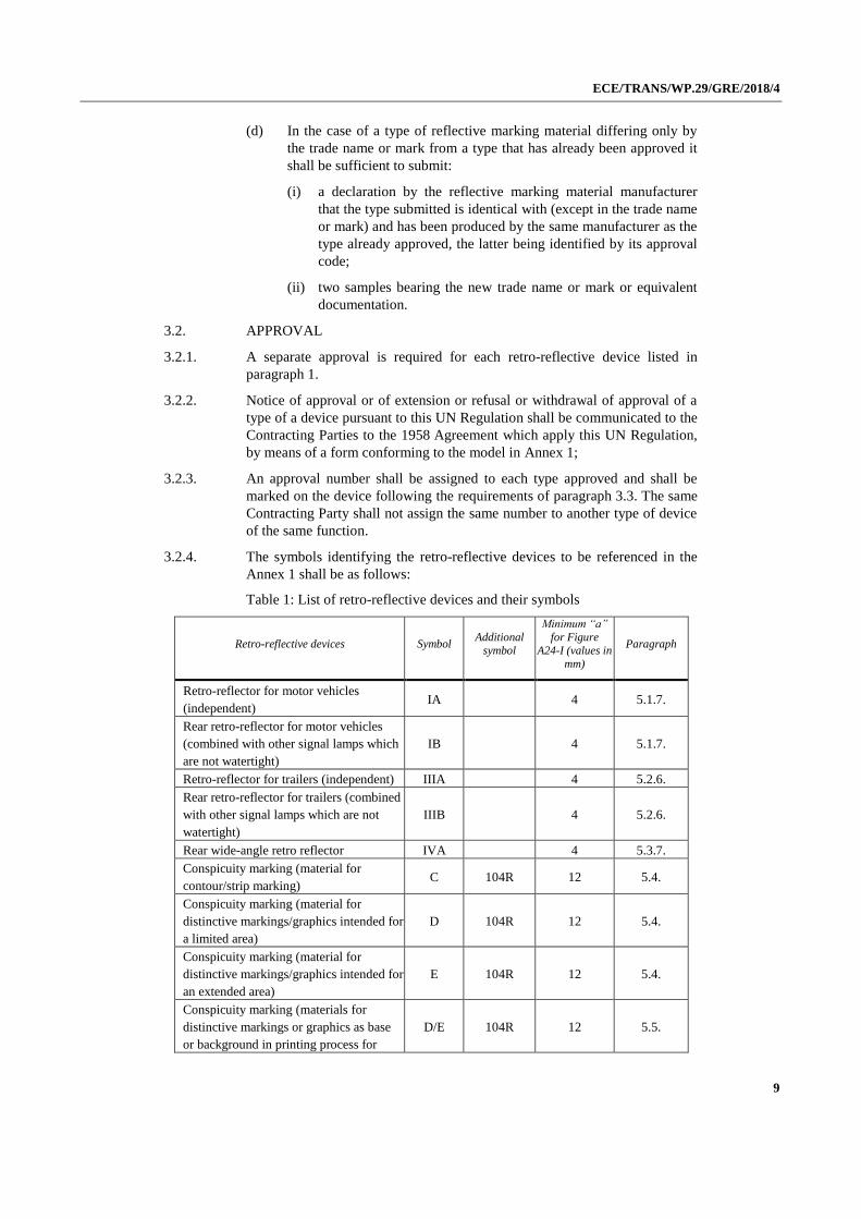
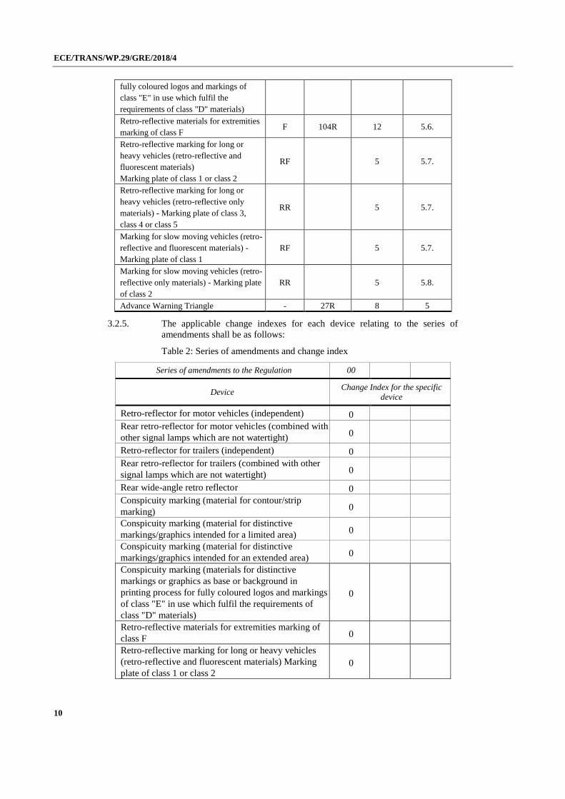
3.2.4. The symbols identifying the retro-reflective devices to be referenced in the
Annex 1 shall be as follows:
Table 1: List of retro-reflective devices and their symbols
Retro-reflective devices Symbol Additional
symbol
Minimum “a”
for Figure
A24-I (values in
mm)
Paragraph
Retro-reflector for motor vehicles
(independent) IA 4 5.1.7.
Rear retro-reflector for motor vehicles
(combined with other signal lamps which
are not watertight)
IB 4 5.1.7.
Retro-reflector for trailers (independent) IIIA 4 5.2.6.
Rear retro-reflector for trailers (combined
with other signal lamps which are not
watertight)
IIIB 4 5.2.6.
Rear wide-angle retro reflector IVA 4 5.3.7.
Conspicuity marking (material for
contour/strip marking) C 104R 12 5.4.
Conspicuity marking (material for
distinctive markings/graphics intended for
a limited area)
D 104R 12 5.4.
Conspicuity marking (material for
distinctive markings/graphics intended for
an extended area)
E 104R 12 5.4.
Conspicuity marking (materials for
distinctive markings or graphics as base
or background in printing process for
D/E 104R 12 5.5.
ECE/TRANS/WP.29/GRE/2018/4
10
fully coloured logos and markings of
class "E" in use which fulfil the
requirements of class "D" materials)
Retro-reflective materials for extremities
marking of class F F 104R 12 5.6.
Retro-reflective marking for long or
heavy vehicles (retro-reflective and
fluorescent materials)
Marking plate of class 1 or class 2
RF 5 5.7.
Retro-reflective marking for long or
heavy vehicles (retro-reflective only
materials) - Marking plate of class 3,
class 4 or class 5
RR 5 5.7.
Marking for slow moving vehicles (retro-
reflective and fluorescent materials) -
Marking plate of class 1
RF 5 5.7.
Marking for slow moving vehicles (retro-
reflective only materials) - Marking plate
of class 2
RR 5 5.8.
Advance Warning Triangle - 27R 8 5
3.2.5. The applicable change indexes for each device relating to the series of
amendments shall be as follows:
Table 2: Series of amendments and change index
Series of amendments to the Regulation 00
Device Change Index for the specific
device
Retro-reflector for motor vehicles (independent) 0
Rear retro-reflector for motor vehicles (combined with
other signal lamps which are not watertight) 0
Retro-reflector for trailers (independent) 0
Rear retro-reflector for trailers (combined with other
signal lamps which are not watertight) 0
Rear wide-angle retro reflector 0
Conspicuity marking (material for contour/strip
marking) 0
Conspicuity marking (material for distinctive
markings/graphics intended for a limited area) 0
Conspicuity marking (material for distinctive
markings/graphics intended for an extended area) 0
Conspicuity marking (materials for distinctive
markings or graphics as base or background in
printing process for fully coloured logos and markings
of class "E" in use which fulfil the requirements of
class "D" materials)
0
Retro-reflective materials for extremities marking of
class F 0
Retro-reflective marking for long or heavy vehicles
(retro-reflective and fluorescent materials) Marking
plate of class 1 or class 2 0
ECE/TRANS/WP.29/GRE/2018/4
11
Retro-reflective marking for long or heavy vehicles
(retro-reflective only materials) Marking plate of class
3, class 4 or class 5 0
Marking for slow moving vehicles (retro-reflective
and fluorescent materials) Marking plate of class 1 0
Marking for slow moving vehicles (retro-reflective
only materials)
Marking plate of class 2 0
Advance Warning Triangle 0
3.3. APPROVAL MARK
3.3.1. General provisions
3.3.1.1. Every device belonging to an approved type shall comprise a space of
sufficient size for the Unique Identifier (UI) as referred to in the 1958
Agreement and other markings as defined in paragraph 3.3.4.2. to 3.3.4.6. or,
if technically not possible, the approval marking with the additional symbols
and other markings as defined in paragraphs 3.3.4.2. to 3.3.4.6.
3.3.1.2. Examples of the arrangement of the markings are shown in Annex 24.
3.3.2. The approval marking shall consist of:
3.3.2.1. A circle surrounding the letter "E" followed by the distinguishing number of
the country which has granted approval.
3.3.2.2. The approval number prescribed in paragraph 3.2.3.2.
3.3.2.3. The symbols identifying the retro-reflective device prescribed in paragraph
3.2.4.
3.3.2.4. The number of this UN Regulation followed by the letter 'R' and the two
digits indicating the series of amendments in force at the time of issue of the
approval.
3.3.2.5. The approval number shall be placed close to the circle prescribed in
paragraph 3.3.2.1.
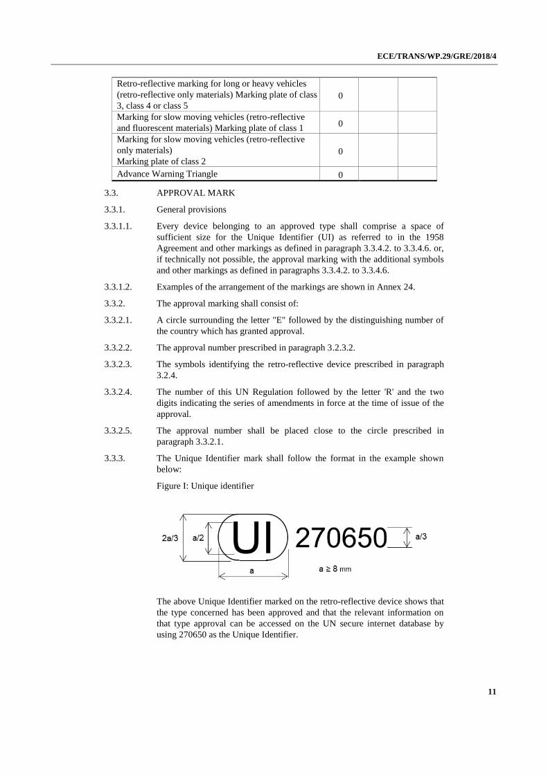
3.3.3. The Unique Identifier mark shall follow the format in the example shown
below:
Figure I: Unique identifier
The above Unique Identifier marked on the retro-reflective device shows that
the type concerned has been approved and that the relevant information on
that type approval can be accessed on the UN secure internet database by
using 270650 as the Unique Identifier.
ECE/TRANS/WP.29/GRE/2018/4
12
3.3.4. MARKING REQUIREMENTS
Retro-reflective devices for approval
3.3.4.1. Comprise a space sufficient size for the approval marking or the Unique
Identifier.
3.3.4.1.1. In any case the approval marking or the Unique Identifier shall be visible
when the retro-reflective device is fitted on the vehicle or when a movable
part such as the hood or boot lid or a door is opened.
3.3.4.1.2. The approval marking shall be placed on an inner or outer part (transparent or
not) of the retro-reflective device which cannot be separated from the
transparent part of the retro-reflective device.
3.3.4.2. Bear the trade name or mark of the applicant; this marking shall be clearly
legible and indelible.
3.3.4.3. The symbols identifying the retro-reflective device, marking materials or
plates and the additional symbols prescribed in Table 1.
3.3.4.4. The approval mark shall be clearly legible and indelible.
3.3.4.5. The approval number and the additional symbols shall be placed close to the
circle prescribed in paragraph 2.2. and either above or below the letter “E”, or
to the right or left of that letter. The digits of the approval number shall be on
the same side of the letter “E” and face the same direction.
3.3.4.6. Examples of the arrangement of vehicle and devices marking are shown in
Annex 24.
3.3.4.7. The space for the approval mark shall be shown in the drawings mentioned in
paragraph 3.1.2.3.;
3.4. MODIFICATIONS OF A TYPE OF RETRO-REFLECTIVE DEVICE FOR
MOTOR VEHICLES AND THEIR TRAILERS AND EXTENSION OF
APPROVAL
3.4.1. Every modification of the type of retro-reflective device shall be notified to
the Type Approval Authority which approved the type. The Authority may
then either:
3.4.1.1. Consider that the modifications made are unlikely to have an appreciable
adverse effect, and that in any case the retro-reflective of device still meets
the requirements; or
3.4.1.2. Require a further report from the technical service responsible for conducting
the tests.
3.4.2. Confirmation or refusal of approval, specifying the alterations, shall be
communicated by the procedure specified in paragraph 3.2.3.1. to the
Contracting Parties to the 1958 Agreement applying this UN Regulation.
3.4.3. The Type Approval Authority issuing the extension of approval shall assign a
series number for such an extension and inform thereof the other Contracting
Parties to the 1958 Agreement applying the UN Regulation under which the
approval has been granted by means of a communication form conforming to
the model in Annex 1.
3.5. CONFORMITY OF PRODUCTION
The conformity of production procedures shall comply with those set out in
ECE/TRANS/WP.29/GRE/2018/4
13
the 1958 Agreement, Schedule 1 (E/ECE/324-E/ECE/TRANS/505/Rev.3),
with the following requirements:
3.5.1. Retro-reflectors approved under this UN Regulation shall be so manufactured
as to conform to the type approved by meeting the requirements set forth in
paragraphs 4 and 5.
3.5.1.1. The minimum requirements for conformity of production control procedures
set forth in Annex 2 shall be complied with.
3.5.1.2. The minimum requirements for sampling by an inspector set forth in Annex 3
shall be complied with.
3.5.2. The authority which has granted type approval may at any time verify the
conformity control methods applied in each production facility. The normal
frequency of these verifications shall be once every two years.
3.5.3. Advance warning triangles approved under this UN Regulation shall be so
manufactured as to conform to the type approved under this UN Regulation.
The compliance with the requirements set forth in paragraphs 4. and 5. shall
be verified as follows:
3.5.3.1. In addition, the stability in time of the optical properties and colour of retro-
reflecting optical units of advance warning triangles conforming to an
approved type and in use shall be verified. In the event of a systematic
deficiency of the retro-reflecting optical units of advance warning triangles in
use and conforming to an approved type, approval may be withdrawn. A
"systematic deficiency" shall be deemed to exist where an approved type of
advance warning triangle fails to meet the requirements of paragraph 5.
3.5.4. Any retro-reflective marking material approved to this UN Regulation shall
be so manufactured as to conform to the type approved by meeting the
requirements set forth in paragraphs 4. and 5.
3.5.4.1. The conformity of production shall not be contested if the mean value of the
photometric measurements of five specimens taken at random deviates
unfavourably by not more than 20 per cent from the prescribed values given
in paragraphs 4. and 5.
3.5.4.2. The conformity of production shall not be contested, if the mean value of the
colorimetric properties of five specimens taken at random meet the
specifications of paragraphs 4. and 5. to be judged by visual inspection.
3.5.4.3. The authority which has granted type approval may at any time verify the
conformity control methods applied in each production facility. The normal
frequency of these verifications shall be once every two years.
3.6. PENALTIES FOR NON-CONFORMITY OF PRODUCTION
3.6.1. The approval granted may be withdrawn if the requirements in this UN
Regulation are not met.
3.6.2. If a Contracting Party to the 1958 Agreement which applies this UN
Regulation withdraws an approval it has previously granted, it shall forthwith
so notify the other Contracting Parties applying this UN Regulation by means
of a communication form conforming to the model in Annex 1.
3.7. PRODUCTION DEFINITIVELY DISCONTINUED
If the holder of the approval completely ceases to manufacture a retro-
ECE/TRANS/WP.29/GRE/2018/4
14
reflective device approved in accordance with this UN Regulation, he shall so
inform the authority which granted the approval. Upon receiving the relevant
communication, that authority shall inform thereof the other Contracting
Parties to the Agreement applying this UN Regulation by means of a
communication form conforming to the model in Annex 1.
3.8. NAME AND ADDRESS OF THE TECHNICAL SERVICES
RESPONSIBLE FOR CONDUCTING APPROVAL TESTS; AND OF
ADMINISTRATIVE DEPARTMENTS
The Contracting Parties to the Agreement applying this UN Regulation shall
communicate to the United Nations secretariat the names and addresses of
the Technical Services responsible for conducting approval tests and of the
Administrative Departments which grant approval and to which forms
certifying approval or extension or refusal or withdrawal of approval, or the
definitive discontinuation of production issued in other countries, are to be
sent.
4. General requirements
4.1. For the purpose of this UN Regulation, retro-reflectors or retro-reflective
materials or marking plates or advance warning triangles for general
descriptions herein after referred to as "retro-reflective devices".
4.1.1. Retro-reflective devices shall be so constructed that they function
satisfactorily and will continue to do so in normal use. In addition, they must
not have any defect in design or manufacture that is detrimental to their
efficient operation or to their maintenance in good condition.
4.1.2. The components of retro-reflective devices or parts thereof shall not be
capable of being easily dismantled.
4.1.3. The means of attachment of the marking materials shall be durable and
stable.
4.1.4. The outer surface of retro-reflective devices shall be easy to clean. The
surface shall therefore not be rough and any protuberances they may exhibit
shall not prevent easy cleaning.
4.1.5. There shall be no access to the inner surface of the retro-reflectors when in
normal use.
4.1.6. Retro-reflective devices may consist of a combined retro-reflecting optical
unit and filter, which must be so designed that they cannot be separated under
normal conditions of use.
4.1.7. The colouring of retro-reflecting optical units and filters by means of paint or
varnish is not permitted.
4.2. COLORIMETRIC TEST CONDITIONS
4.2.1. Test procedure for night time colours:
4.2.1.1. These specifications shall apply only to clear, red or amber retro-reflective
devices
4.2.1.2. For testing the colour of the retro-reflective device, this device shall be
illuminated by the CIE Standard Illuminant A, with an angle of divergence of
1/3 degrees and an illumination angle of V = H = 0 degree, or, if this
ECE/TRANS/WP.29/GRE/2018/4
15
produces a colourless surface reflection, an angle V = +/- 5 degrees, H = 0
degree, the trichromatic coordinates of the reflected luminous flux must be
within the limits according to the specifications for the individual
retroreflecting device in paragraph 4.
4.2.1.3. Clear retro-reflective devices must not produce a selective reflection, that is
to say, the trichromatic coordinates "x" and "y" of the standard illuminant
"A" used to illuminate the retro-reflective device must not undergo a change
of more than 0.01 after reflection by the retro-reflective device.
4.2.2. Test procedure for day time colours:
4.2.2.1. For testing the day time colour of the materials, the material shall be
illuminated by the CIE Standard Illuminant D 65 at an angle of 45° to the
normal and viewed (measured) along the normal (45/0 geometry), with a
spectrophotometer in accordance with the provisions of CIE document
No. 15 (1971).
The colour of the material in new condition shall be within the limits
according to the specifications for the individual retro-reflective device in
paragraph 5.9.5.2.2.
4.2.3. Test procedure for fluorescent colours:
4.2.3.1. Colour of the fluorescent material without retro-reflection:
4.2.3.1.1. For testing the colour of the fluorescent material, the material shall be
illuminated by the CIE Standard Illuminant D65 (ISO 11664-2:2007(E)/CIE
S 014-2/E:2006) and measured with a spectrophotometer in accordance with
the provisions of Publication CIE 15:2004, Recommendations on
Colorimetry - Second Edition, either illuminated polychromatically or with a
monochromator providing stepwise the CIE Standard Illuminant D 65 (ISO
11664-2:2007(E)/CIE S 014-2/E:2006) at an angle 45º to the normal and
viewed along the normal (geometry 45/0). In the latter case, the stepwise
resolution λ shall be not larger than 10 nm. Alternatively, similar
"illuminants" are allowed, if verified that the colorimetric measuring
procedure is of the same sufficient accuracy, meaning that the quality of the
simulation of D65 shall be assessed by the method described in ISO
23603:2005(E)/CIE S 012/E:2004. The spectral distribution of the illuminant
shall be in category BC (CIELAB) or better.
The illumination shall be carried out at an angle 45º to the normal and viewed
along the normal (geometry 45/0).
4.2.3.2. Colour of the fluorescent material with retro-reflection:
4.2.3.2.1. For testing the colour of the fluorescent material, the material shall be
illuminated by the CIE Standard Illuminant D65 (ISO 11664-2:2007(E)/CIE
S 014-2/E:2006) and measured with a spectrophotometer in accordance with
the provisions of publication CIE 15:2004, Recommendations on
Colorimetry - second edition, either illuminated polychromatically or with a
monochromator providing stepwise the CIE Standard Illuminant D 65 (ISO
11664-2:2007(E)/CIE S 014-2/E:2006). In the latter case, the stepwise
resolution λ shall be not larger than 10 nm. Alternatively, similar
"illuminants" are allowed, if verified that the colorimetric measuring
procedure is of the same sufficient accuracy, meaning that the quality of the
simulation of D65 shall be assessed by the method described in ISO
23603:2005(E)/CIE S 012/E:2004. The spectral distribution of the illuminant
ECE/TRANS/WP.29/GRE/2018/4
16
shall be in category BC (CIELAB) or better. The illumination shall be carried
out circumferential at an angle 45º to the normal and viewed along the
normal (annular geometry 45/0) (circumferential/normal geometry), as
described in Annex 23.
4.3. DETERMINATION OF THE LUMINANCE FACTOR:
4.3.1. For the determination of the luminance factor, the sample shall be tested
(a) For retro-reflective devices without fluorescence (day time colours)
and fluorescent material without retro-reflection with the same method
as described in paragraph 4.2.3.1.;
(b) For fluorescent material with retro-reflection with the same method as
described in paragraph 4.2.3.2.
4.3.1.1. By putting the luminance L of the sample into relation to the luminance Lo of
a perfect diffuser whose luminance factor o is known under identical
conditions of illumination and observation; the luminance factor of the
sample then results from the formula:
o
oL
L
4.3.1.2. When the colour of the fluorescent material has been colorimetrically
determined in compliance with paragraph 4.2.3., from the ratio of the
tristimulus value Y the sample and the tristimulus value of the perfect
diffuser Yo in this case it is:
0Y
Y
5. Specific technical requirements
5.1. TECHNICAL REQUIREMENTS CONCERNING RETRO-REFLECTORS
OF THE CLASSES IA AND IB (SYMBOLS "IA" AND "IB")
5.1.1. Every retro-reflector of the Classes IA and IB, when tested according to
paragraph 5.1.7., shall meet:
(a) the dimensions and shape requirements set forth in Annex 5; and
(b) the photometric and colorimetric requirements as specified in
paragraphs 5.1.4. to 5.1.5.; and
(c) the physical and mechanical requirements set forth in paragraph
4.1.6., depending on the nature of the materials and construction of the
retro-reflective devices.
5.1.2. The applicant shall submit ten samples for approval which shall be tested in
the chronological order as indicated in paragraph 5.1.7.
5.1.3. Test procedure.
5.1.3.1. After verification of the general specifications (paragraph 2.) and the
specifications of shape and dimensions (Annex 5), the ten samples shall be
subjected to the heat resistance test described in Annex 6 and at least one
hour after this test examined as to their colorimetric characteristics and CIL
in paragraph 4.1.4., for an angle of divergence of 20' and an illumination
ECE/TRANS/WP.29/GRE/2018/4
17
angle V = H = 0° or if necessary, in the position defined in paragraph 5.1.4.
The two retro-reflective devices giving the minimum and maximum values
shall then be fully tested as shown in paragraph 4.1.4.
These two samples shall be kept by the laboratories for any further checks
which may be found necessary.
The other eight samples shall be divided into four groups of two:
First group: The two samples shall be subjected successively to the
water penetration test (Annex 7) and then, if this test is
satisfactory, to the tests for resistance to fuels and
lubricants (Annex 9 and Annex 10).
Second group: The two samples shall, if necessary, be subjected to the
corrosion test in Annex 11, and then to the abrasive-
strength test of the rear face of the retro-reflective
device Annex 12.
Third group: The two samples shall be subjected to the test for
stability in time of the optical properties of retro-
reflective device Annex 14.
Fourth group: The two samples shall be subjected to the colour-
fastness test (Annex 21).
5.1.3.2. After undergoing the tests referred to in the paragraph 4.1.3.1., the retro-
reflective devices in each group must have:
5.1.3.2.1. a colour which satisfies the conditions laid down in paragraph 4.1.5.
5.1.3.2.2. a CIL which satisfies the conditions laid down in paragraph 4.1.4. The
verification shall be performed only for an angle of divergence of 20' and an
illumination angle of V = H = 0° or, if necessary, in all positions specified in
paragraph 4.1.4.
5.1.4. Minimum values for the CIL values of retro-reflection
5.1.4.1. When applying for approval, the applicant shall specify one or more or a
range of axis of reference, corresponding to the illumination angle
V = H = 0° in the table of coefficients of luminous intensity (CIL).
5.1.4.2. In the case where more than one or a range of different axis of reference are
specified by the manufacturer, the photometric measurements shall be
repeated making reference each time to a different axis of reference or to the
extreme axis of reference of the range specified by the manufacturer.
5.1.4.3. For photometric measurements, only the illuminating surface defined by the
planes contiguous to the outermost parts of the optical system of the retro-
reflective device as indicated by the manufacturer and contained within a
circle of 200 mm diameter for Class IA or IB shall be considered, and the
illuminating surface itself shall be limited to 100 cm2 though the surfaces of
the retro-reflecting optical units need not necessarily attain this area. The
manufacturer shall specify the perimeter of the area to be used.
5.1.4.4. Class IA and Class IB
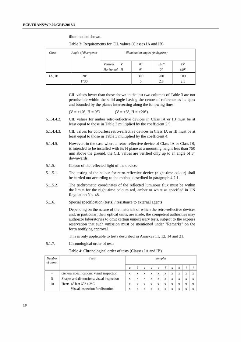
5.1.4.4.1. When measured as described in paragraph 3. and Annex 4, the CIL values for
red retro-reflective devices must be equal to or greater than those in Table 3,
expressed in millicandelas per lux, for the angles of divergence and
ECE/TRANS/WP.29/GRE/2018/4
18
illumination shown.
Table 3: Requirements for CIL values (Classes IA and IB)
Class Angle of divergence
α
Illumination angles (in degrees)
Vertical V
Horizontal H
0°
0°
±10°
0°
±5°
±20°
IA, IB 20'
1°30'
300
5
200
2.8
100
2.5
CIL values lower than those shown in the last two columns of Table 3 are not
permissible within the solid angle having the centre of reference as its apex
and bounded by the planes intersecting along the following lines:
(V = ±10°, H = 0°) (V = ±5°, H = ±20°).
5.1.4.4.2. CIL values for amber retro-reflective devices in Class IA or IB must be at
least equal to those in Table 3 multiplied by the coefficient 2.5.
5.1.4.4.3. CIL values for colourless retro-reflective devices in Class IA or IB must be at
least equal to those in Table 3 multiplied by the coefficient 4.
5.1.4.5. However, in the case where a retro-reflective device of Class IA or Class IB,
is intended to be installed with its H plane at a mounting height less than 750
mm above the ground, the CIL values are verified only up to an angle of 5°
downwards.
5.1.5. Colour of the reflected light of the device:
5.1.5.1. The testing of the colour for retro-reflective device (night-time colour) shall
be carried out according to the method described in paragraph 4.2.1.
5.1.5.2. The trichromatic coordinates of the reflected luminous flux must be within
the limits for the night-time colours red, amber or white as specified in UN
Regulation No. 48.
5.1.6. Special specification (tests) / resistance to external agents
Depending on the nature of the materials of which the retro-reflective devices
and, in particular, their optical units, are made, the competent authorities may
authorize laboratories to omit certain unnecessary tests, subject to the express
reservation that such omission must be mentioned under "Remarks" on the
form notifying approval.
This is only applicable to tests described in Annexes 11, 12, 14 and 21.
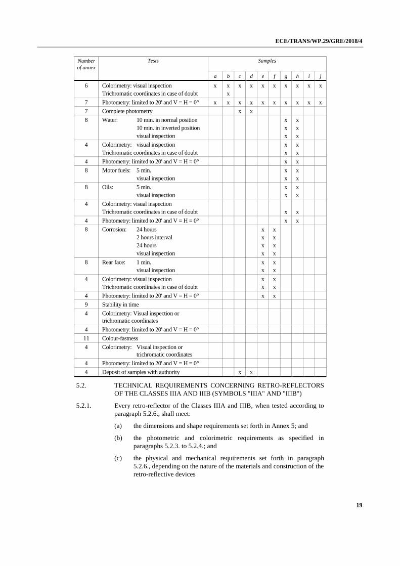
5.1.7. Chronological order of tests
Table 4: Chronological order of tests (Classes IA and IB)
Number
of annex
Tests Samples
a b c d e f g h i j
- General specifications: visual inspection x x x x x x x x x x
5 Shapes and dimensions: visual inspection x x x x x x x x x x
10 Heat: 48 h at 65° ± 2°C
Visual inspection for distortion
x
x
x
x
x
x
x
x
x
x
x
x
x
x
x
x
x
x
x
x
ECE/TRANS/WP.29/GRE/2018/4
19
Number
of annex
Tests Samples
a b c d e f g h i j
6 Colorimetry: visual inspection
Trichromatic coordinates in case of doubt
x
x
x
x x x x x x x x
7 Photometry: limited to 20' and V = H = 0° x x x x x x x x x x
7 Complete photometry x x
8 Water: 10 min. in normal position
10 min. in inverted position
visual inspection
x
x
x
x
x
x
4 Colorimetry: visual inspection
Trichromatic coordinates in case of doubt
x
x
x
x
4 Photometry: limited to 20' and V = H = 0° x x
8 Motor fuels: 5 min.
visual inspection
x
x
x
x
8 Oils: 5 min.
visual inspection
x
x
x
x
4 Colorimetry: visual inspection
Trichromatic coordinates in case of doubt
x
x
4 Photometry: limited to 20' and V = H = 0° x x
8 Corrosion: 24 hours
2 hours interval
24 hours
visual inspection
x
x
x
x
x
x
x
x
8 Rear face: 1 min.
visual inspection
x
x
x
x
4 Colorimetry: visual inspection
Trichromatic coordinates in case of doubt
x
x
x
x
4 Photometry: limited to 20' and V = H = 0° x x
9 Stability in time
4 Colorimetry: Visual inspection or
trichromatic coordinates
4 Photometry: limited to 20' and V = H = 0°
11 Colour-fastness
4 Colorimetry: Visual inspection or
trichromatic coordinates
4 Photometry: limited to 20' and V = H = 0°
4 Deposit of samples with authority x x
5.2. TECHNICAL REQUIREMENTS CONCERNING RETRO-REFLECTORS
OF THE CLASSES IIIA AND IIIB (SYMBOLS "IIIA" AND "IIIB")
5.2.1. Every retro-reflector of the Classes IIIA and IIIB, when tested according to
paragraph 5.2.6., shall meet:
(a) the dimensions and shape requirements set forth in Annex 5; and
(b) the photometric and colorimetric requirements as specified in
paragraphs 5.2.3. to 5.2.4.; and
(c) the physical and mechanical requirements set forth in paragraph
5.2.6., depending on the nature of the materials and construction of the
retro-reflective devices
ECE/TRANS/WP.29/GRE/2018/4
20
5.2.2. The applicant shall submit ten samples for approval which shall be tested in
the chronological order as indicated in paragraph 5.2.7.
5.2.2.1. After verification of the general specifications (paragraph 4.) and the
specifications of shape and dimensions (Annex 5), the ten samples shall be
subjected to the heat resistance test described in Annex 6 and at least one
hour after this test examined as to their colorimetric characteristics and CIL
in paragraph 5.2.3., for an angle of divergence of 20' and an illumination
angle V = H = 0° or if necessary, in the position defined in paragraph 5.2.2.2.
The two retro-reflective devices giving the minimum and maximum values
shall then be fully tested as shown in paragraph 5.2.4.
These two samples shall be kept by the laboratories for any further checks
which may be found necessary.
The other eight samples shall be divided into four groups of two:
First group: The two samples shall be subjected successively to the
water penetration test (Annex 7) and then, if this test is
satisfactory, to the tests for resistance to fuels and
lubricants (Annex 9 and Annex 10).
Second group: The two samples shall, if necessary, be subjected to the
corrosion test in Annex 11, and then to the abrasive-
strength test of the rear face of the retro-reflective
device Annex 12.
Third group: The two samples shall be subjected to the test for
stability in time of the optical properties of retro-
reflective device Annex 14.
Fourth group: The two samples shall be subjected to the colour-
fastness test (Annex 21).
5.2.2.2. After undergoing the tests referred to in the paragraph 5.2.2.1., the retro-
reflective devices in each group must have:
5.2.2.2.1. a colour which satisfies the conditions laid down in paragraph 5.2.4.;
5.2.2.2.2. a CIL which satisfies the conditions laid down in paragraph 5.2.3. The
verification shall be performed only for an angle of divergence of 20' and an
illumination angle of V = H = 0° or, if necessary, in all positions specified in
paragraph 5.2.3.
5.2.3. Minimum values for the CIL values of retro-reflection:
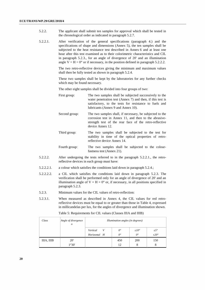
5.2.3.1. When measured as described in Annex 4, the CIL values for red retro-
reflective devices must be equal to or greater than those in Table 4, expressed
in millicandelas per lux, for the angles of divergence and illumination shown.
Table 5: Requirements for CIL values (Classes IIIA and IIIB)
Class Angle of divergence
α
Illumination angles (in degrees)
Vertical V
Horizontal H
0°
0°
±10°
0°
±5°
±20°
IIIA, IIIB 20'
1°30'
450
12
200
8
150
8
ECE/TRANS/WP.29/GRE/2018/4
21
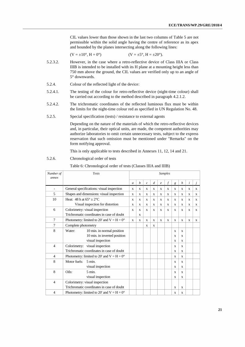
CIL values lower than those shown in the last two columns of Table 5 are not
permissible within the solid angle having the centre of reference as its apex
and bounded by the planes intersecting along the following lines:
(V = ±10°, H = 0°) (V = ±5°, H = ±20°).
5.2.3.2. However, in the case where a retro-reflective device of Class IIIA or Class
IIIB is intended to be installed with its H plane at a mounting height less than
750 mm above the ground, the CIL values are verified only up to an angle of
5° downwards.
5.2.4. Colour of the reflected light of the device:
5.2.4.1. The testing of the colour for retro-reflective device (night-time colour) shall
be carried out according to the method described in paragraph 4.2.1.2.
5.2.4.2. The trichromatic coordinates of the reflected luminous flux must be within
the limits for the night-time colour red as specified in UN Regulation No. 48.
5.2.5. Special specification (tests) / resistance to external agents
Depending on the nature of the materials of which the retro-reflective devices
and, in particular, their optical units, are made, the competent authorities may
authorize laboratories to omit certain unnecessary tests, subject to the express
reservation that such omission must be mentioned under "Remarks" on the
form notifying approval.
This is only applicable to tests described in Annexes 11, 12, 14 and 21.
5.2.6. Chronological order of tests
Table 6: Chronological order of tests (Classes IIIA and IIIB)
Number of
annex
Tests Samples
a b c d e f g h i j
- General specifications: visual inspection x x x x x x x x x x
5 Shapes and dimensions: visual inspection x x x x x x x x x x
10 Heat: 48 h at 65° ± 2°C
Visual inspection for distortion
x
x
x
x
x
x
x
x
x
x
x
x
x
x
x
x
x
x
x
x
6 Colorimetry: visual inspection
Trichromatic coordinates in case of doubt
x
x
x
x x x x x x x x
7 Photometry: limited to 20' and V = H = 0° x x x x x x x x x x
7 Complete photometry x x
8 Water: 10 min. in normal position
10 min. in inverted position
visual inspection
x
x
x
x
x
x
4 Colorimetry: visual inspection
Trichromatic coordinates in case of doubt
x
x
x
x
4 Photometry: limited to 20' and V = H = 0° x x
8 Motor fuels: 5 min.
visual inspection
x
x
x
x
8 Oils: 5 min.
visual inspection
x
x
x
x
4 Colorimetry: visual inspection
Trichromatic coordinates in case of doubt
x
x
4 Photometry: limited to 20' and V = H = 0° x x
ECE/TRANS/WP.29/GRE/2018/4
22
Number of
annex
Tests Samples
a b c d e f g h i j
8 Corrosion: 24 hours
2 hours interval
24 hours
visual inspection
x
x
x
x
x
x
x
x
8 Rear face: 1 min.
visual inspection
x
x
x
x
4 Colorimetry: visual inspection
Trichromatic coordinates in case of doubt
x
x
x
x
4 Photometry: limited to 20' and V = H = 0° x x
9 Stability in time
4 Colorimetry: Visual inspection or
trichromatic coordinates
4 Photometry: limited to 20' and V = H = 0°
11 Colour-fastness
4 Colorimetry: Visual inspection or
trichromatic coordinates
4 Photometry: limited to 20' and V = H = 0°
4 Deposit of samples with authority x x
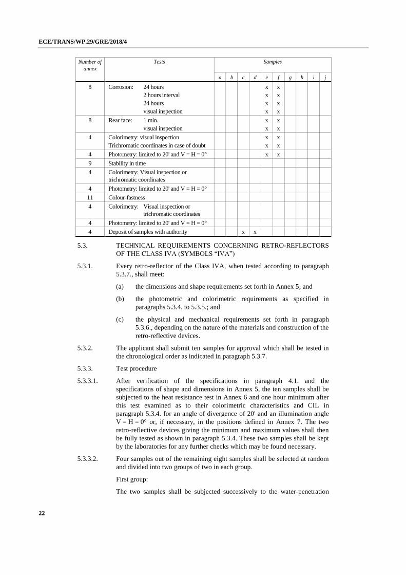
5.3. TECHNICAL REQUIREMENTS CONCERNING RETRO-REFLECTORS
OF THE CLASS IVA (SYMBOLS “IVA”)
5.3.1. Every retro-reflector of the Class IVA, when tested according to paragraph
5.3.7., shall meet:
(a) the dimensions and shape requirements set forth in Annex 5; and
(b) the photometric and colorimetric requirements as specified in
paragraphs 5.3.4. to 5.3.5.; and
(c) the physical and mechanical requirements set forth in paragraph
5.3.6., depending on the nature of the materials and construction of the
retro-reflective devices.
5.3.2. The applicant shall submit ten samples for approval which shall be tested in
the chronological order as indicated in paragraph 5.3.7.
5.3.3. Test procedure
5.3.3.1. After verification of the specifications in paragraph 4.1. and the
specifications of shape and dimensions in Annex 5, the ten samples shall be
subjected to the heat resistance test in Annex 6 and one hour minimum after
this test examined as to their colorimetric characteristics and CIL in
paragraph 5.3.4. for an angle of divergence of 20' and an illumination angle
V = H = 0° or, if necessary, in the positions defined in Annex 7. The two
retro-reflective devices giving the minimum and maximum values shall then
be fully tested as shown in paragraph 5.3.4. These two samples shall be kept
by the laboratories for any further checks which may be found necessary.
5.3.3.2. Four samples out of the remaining eight samples shall be selected at random
and divided into two groups of two in each group.
First group:
The two samples shall be subjected successively to the water-penetration
ECE/TRANS/WP.29/GRE/2018/4
23
resistance test in Annex 7 and then, if this test is satisfactory, to the tests for
resistance to fuels and lubricating oils in Annex 9 and Annex 10.
Second group:
The two samples shall, if relevant, be subjected to the corrosion test
(Annex 11), and then to the abrasive-strength test of the rear face of the retro-
reflective device in Annex 12, these two samples shall also be subjected to
the impact test in Annex 18).
5.3.3.3. After undergoing the tests referred to in the above paragraph, the retro-
reflective devices in each group must have:
5.3.3.3.1. A colour which satisfies the conditions laid down in paragraph 4.2.1. This
shall be verified by a qualitative method and, in case of doubt, confirmed by
a quantitative method;
5.3.3.3.2. A CIL which satisfies the conditions laid down in paragraph 5.3.4.
Verification shall be performed only for an angle of divergence of 20' and an
illumination angle of V = H = 0° or, if necessary, in the positions specified in
paragraph 5.3.4.
5.3.3.4. The four remaining samples can be utilized, if necessary, for any other
purpose.
Every Retro-reflectors of the Classes IVA shall meet the requirements of the
checks and tests described in paragraph 5.3.4.
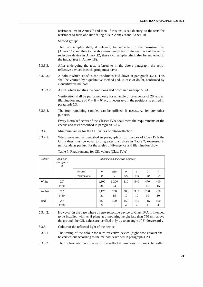
5.3.4. Minimum values for the CIL values of retro-reflection
5.3.4.1. When measured as described in paragraph 3., for devices of Class IVA the
CIL values must be equal to or greater than those in Table 7, expressed in
millicandelas per lux, for the angles of divergence and illumination shown.
Table 7: Requirements for CIL values (Class IVA)
Colour Angle of
divergence
α
Illumination angles (in degrees)
Vertical V
Horizontal H
0
0
±10
0
0
±20
0
±30
0
±40
0
±50
White 20'
1°30'
1,800
34
1,200
24
610
15
540
15
470
15
400
15
Amber 20'
1°30'
1,125
21
750
15
380
10
335
10
290
10
250
10
Red 20'
1°30'
450
9
300
6
150
4
135
4
115
4
100
4
5.3.4.2. However, in the case where a retro-reflective device of Class IVA is intended
to be installed with its H plane at a mounting height less than 750 mm above
the ground, the CIL values are verified only up to an angle of 5° downwards.
5.3.5. Colour of the reflected light of the device
5.3.5.1. The testing of the colour for retro-reflective device (night-time colour) shall
be carried out according to the method described in paragraph 4.2.1.
5.3.5.2. The trichromatic coordinates of the reflected luminous flux must be within
ECE/TRANS/WP.29/GRE/2018/4
24
the limits for the night-time colours red, amber or white as specified in UN
Regulation No. 48.
5.3.6. Special specification (tests) / resistance to external agents
Depending on the nature of the materials of which the retro-reflective devices
and, in particular, their optical units, are made, the competent authorities may
authorize laboratories to omit certain unnecessary tests, subject to the express
reservation that such omission must be mentioned under "Remarks" on the
form notifying approval.
This is only applicable to tests described in Annexes 11, 12, 14 and 21.
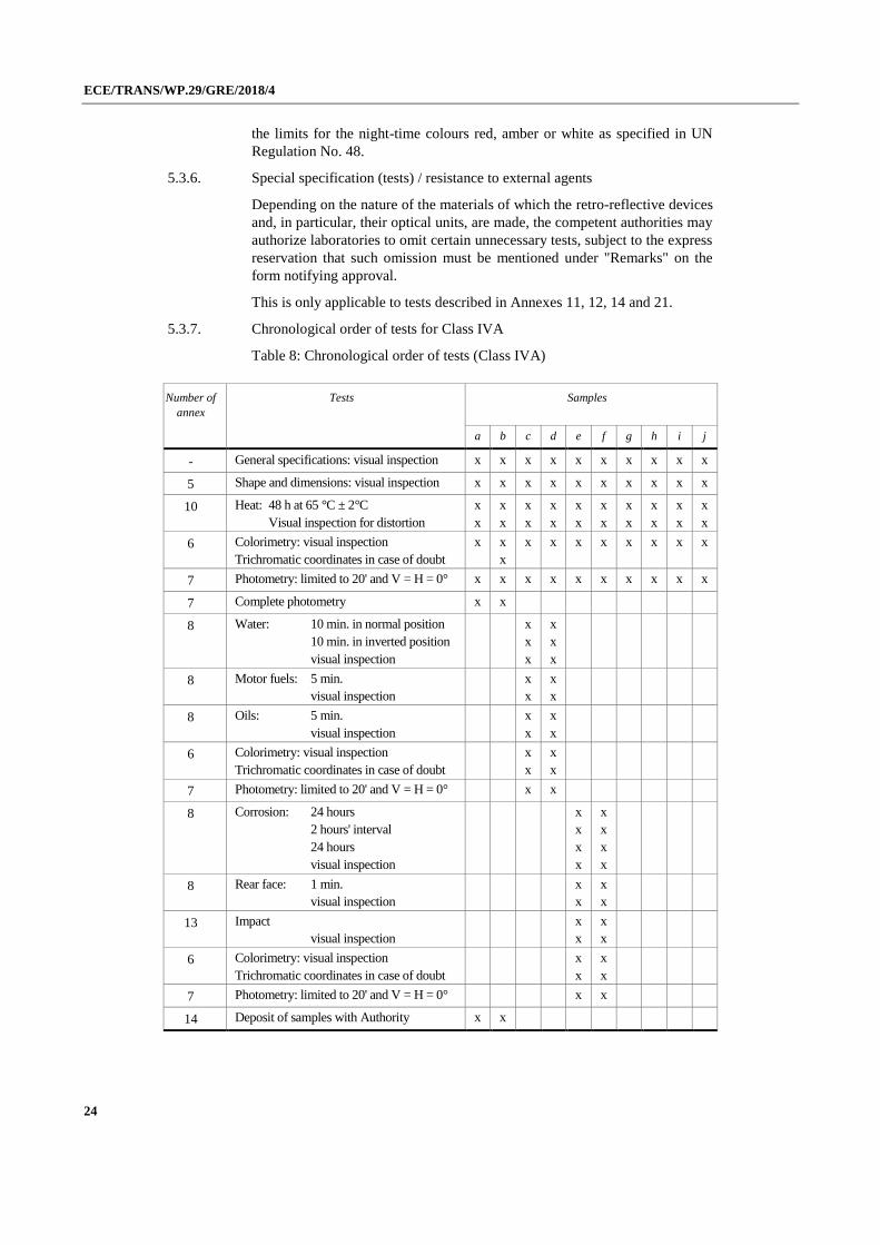
5.3.7. Chronological order of tests for Class IVA
Table 8: Chronological order of tests (Class IVA)
Number of
annex
Tests Samples
a b c d e f g h i j
- General specifications: visual inspection x x x x x x x x x x
5 Shape and dimensions: visual inspection x x x x x x x x x x
10 Heat: 48 h at 65 °C ± 2°C
Visual inspection for distortion
x
x
x
x
x
x
x
x
x
x
x
x
x
x
x
x
x
x
x
x
6 Colorimetry: visual inspection
Trichromatic coordinates in case of doubt
x
x
x
x x x x x x x x
7 Photometry: limited to 20' and V = H = 0° x x x x x x x x x x
7 Complete photometry x x
8 Water: 10 min. in normal position
10 min. in inverted position
visual inspection
x
x
x
x
x
x
8 Motor fuels: 5 min.
visual inspection
x
x
x
x
8 Oils: 5 min.
visual inspection
x
x
x
x
6 Colorimetry: visual inspection
Trichromatic coordinates in case of doubt
x
x
x
x
7 Photometry: limited to 20' and V = H = 0° x x
8 Corrosion: 24 hours
2 hours' interval
24 hours
visual inspection
x
x
x
x
x
x
x
x
8 Rear face: 1 min.
visual inspection
x
x
x
x
13 Impact
visual inspection
x
x
x
x
6 Colorimetry: visual inspection
Trichromatic coordinates in case of doubt
x
x
x
x
7 Photometry: limited to 20' and V = H = 0° x x
14 Deposit of samples with Authority x x
ECE/TRANS/WP.29/GRE/2018/4
25
5.4. TECHNICAL REQUIREMENTS CONCERNING RETRO-REFLECTIVE
MARKINGS OF THE CLASSES C (SYMBOLS “C”)
5.4.1. Every retro-reflective marking of the Classes C and F, when tested according
to paragraph 5.4.3., shall meet:
(a) the dimensions and shape requirements set forth in Annex 5; and
(b) the photometric and colorimetric requirements as specified in
paragraphs 5.4.4. to 5.4.5.; and
(c) the physical and mechanical requirements set forth in paragraph 5.4.6.
5.4.2. The applicant shall submit for approval:
5.4.2.1. Five test samples representing strips of retro-reflective marking materials
have to be submitted to the test laboratory. In the case of strips, at least a
length of 3 meters shall be provided
5.4.2.2. The test samples shall be representative of current production, manufactured
in accordance with the recommendation of the manufacturer(s) of the retro-
reflective marking materials. 1
5.4.2.3. The samples shall be tested in the chronological order indicated in paragraph
5.
5.4.3. Test procedure
5.4.3.1. After verification of the general specifications (paragraph 3.) and the
specifications of shape and dimensions (Annex 5), the samples shall be
subjected to the heat resistance test described in Annex 6, prior to the tests
described in the paragraphs 5.4.4. and 5.4.5.
5.4.3.2. The photometric and colorimetric measurements may be made on five
samples. The mean values should be taken.
5.4.3.3. For other tests, samples which have not undergone any testing should be
used.
5.4.4. Minimum values for the coefficient of retro-reflection
Photometric specifications for retro-reflective markings of Classes C and F:
5.4.4.1. When measured as described in Annex 4, the coefficient of retro-reflection R'
in candelas per m2 per lux (cd/m2/lux) of the retro-reflective areas in new
condition shall be at least as indicated in Table 9 for white, yellow and red
materials.
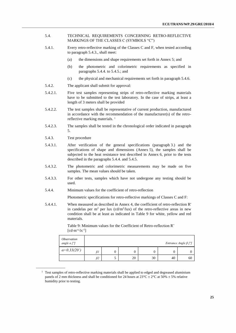
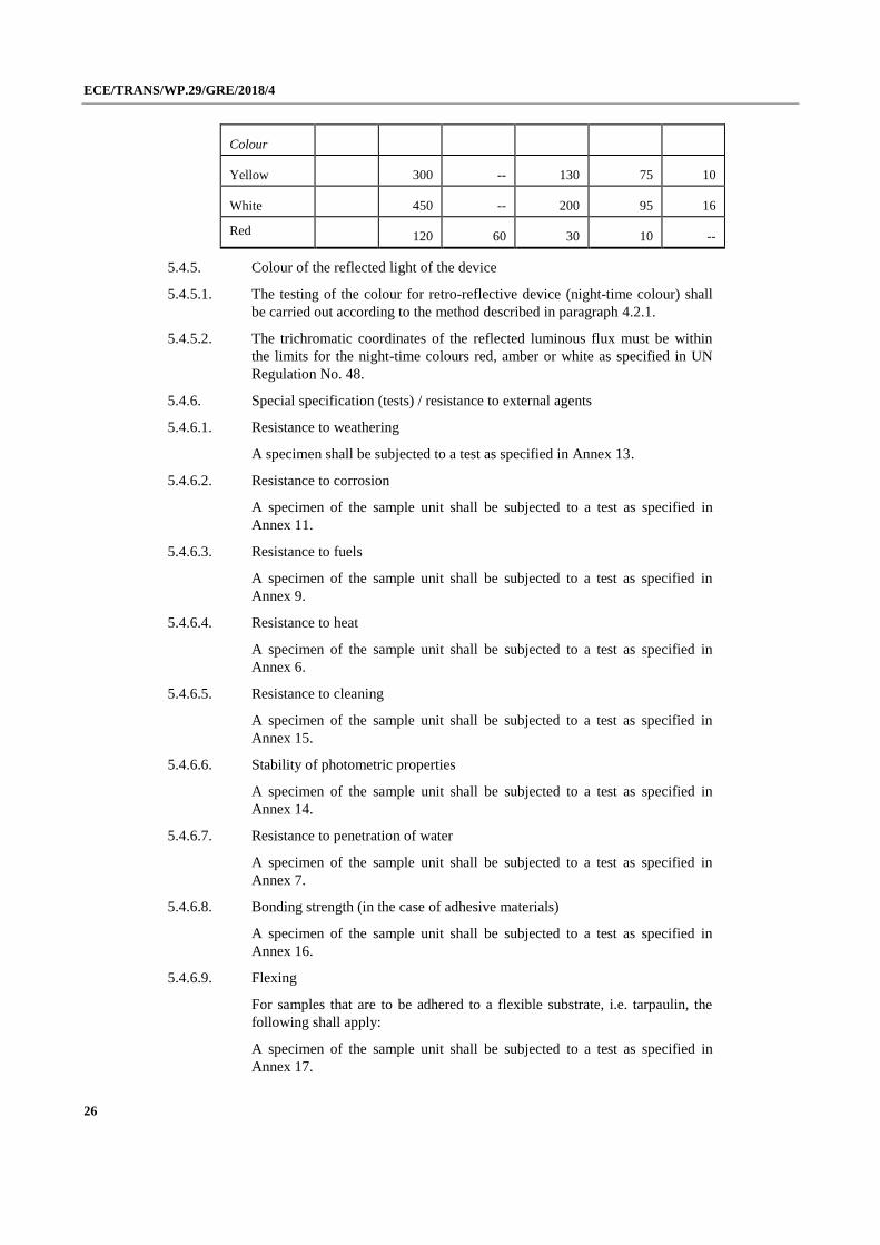
Table 9: Minimum values for the Coefficient of Retro-reflection R’
[cd∙m-²∙lx-1]
Observation
angle α [º] Entrance Angle β [º]
α=0.33(20’) β1 0 0 0 0 0
β2 5 20 30 40 60
1 Test samples of retro-reflective marking materials shall be applied to edged and degreased aluminium
panels of 2 mm thickness and shall be conditioned for 24 hours at 23°C ± 2°C at 50% ± 5% relative
humidity prior to testing.
ECE/TRANS/WP.29/GRE/2018/4
26
Colour
Yellow 300 -- 130 75 10
White 450 -- 200 95 16
Red 120 60 30 10 --
5.4.5. Colour of the reflected light of the device
5.4.5.1. The testing of the colour for retro-reflective device (night-time colour) shall
be carried out according to the method described in paragraph 4.2.1.
5.4.5.2. The trichromatic coordinates of the reflected luminous flux must be within
the limits for the night-time colours red, amber or white as specified in UN
Regulation No. 48.
5.4.6. Special specification (tests) / resistance to external agents
5.4.6.1. Resistance to weathering
A specimen shall be subjected to a test as specified in Annex 13.
5.4.6.2. Resistance to corrosion
A specimen of the sample unit shall be subjected to a test as specified in
Annex 11.
5.4.6.3. Resistance to fuels
A specimen of the sample unit shall be subjected to a test as specified in
Annex 9.
5.4.6.4. Resistance to heat
A specimen of the sample unit shall be subjected to a test as specified in
Annex 6.
5.4.6.5. Resistance to cleaning
A specimen of the sample unit shall be subjected to a test as specified in
Annex 15.
5.4.6.6. Stability of photometric properties
A specimen of the sample unit shall be subjected to a test as specified in
Annex 14.
5.4.6.7. Resistance to penetration of water
A specimen of the sample unit shall be subjected to a test as specified in
Annex 7.
5.4.6.8. Bonding strength (in the case of adhesive materials)
A specimen of the sample unit shall be subjected to a test as specified in
Annex 16.
5.4.6.9. Flexing
For samples that are to be adhered to a flexible substrate, i.e. tarpaulin, the
following shall apply:
A specimen of the sample unit shall be subjected to a test as specified in
Annex 17.
ECE/TRANS/WP.29/GRE/2018/4
27
5.4.7. Chronological order of tests for Classes C
5.4.7.1. Five test samples representing either strips or planes of retro-reflective
marking materials have to be submitted to the test laboratory. In the case of
strips, at least a length of 3 meters shall be provided; in the case of planes, at
least a surface of 500 mm x 500 mm shall be provided.
5.4.7.2. The test samples shall be representative of current production, manufactured
in accordance with the recommendation of the manufacturer(s) of the retro-
reflective marking materials. 2
5.4.7.3. After verification of the general specifications (paragraph 4.) and the
specifications of shape and dimensions (Annex 5), the samples shall be
subjected to the heat resistance test described in Annex 8, prior to the tests
described in Annexes 6 and 7.
5.4.7.4. The photometric and colorimetric measurements may be made on five
samples. The mean values should be taken.
5.4.7.5. For other tests, samples which have not undergone any testing should be
used.
5.5. TECHNICAL REQUIREMENTS CONCERNING RETRO-REFLECTIVE
MARKINGS OF THE CLASSES D AND E (SYMBOLS “D” AND “E”)
5.5.1. Every retro-reflective marking of the Classes D and E shall meet the
photometric requirements as specified in paragraphs 5.5.3. to 5.5.5.
5.5.2. The applicant shall submit for approval:
5.5.2.1. Five test samples representing planes of retro-reflective marking materials
have to be submitted to the test laboratory. In the case of planes, at least a
surface of 500 mm x 500 mm shall be provided.
5.5.2.2. The test samples shall be representative of current production, manufactured
in accordance with the recommendation of the manufacturer(s) of the retro-
reflective marking materials. 3
5.5.3. Test procedure
Every retro-reflective marking of the Class D and E shall meet the
requirements of the checks and tests described in paragraph 5.5.5.
5.5.4. Maximum values for the coefficient of retro-reflection
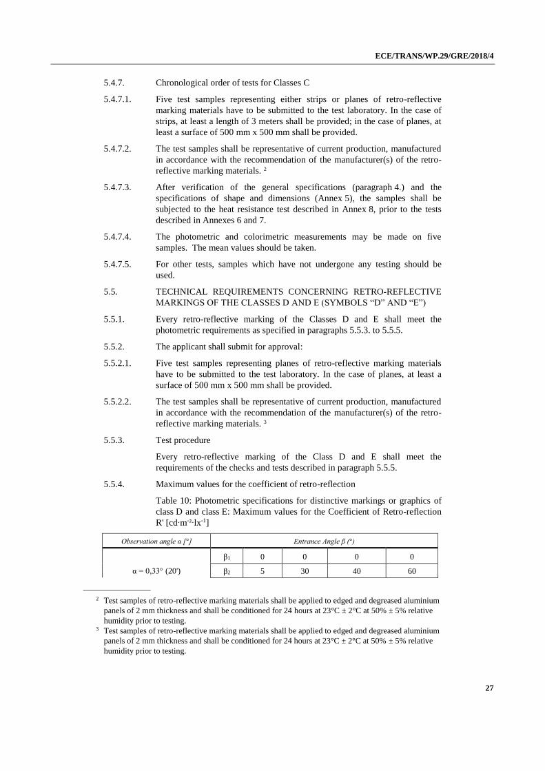
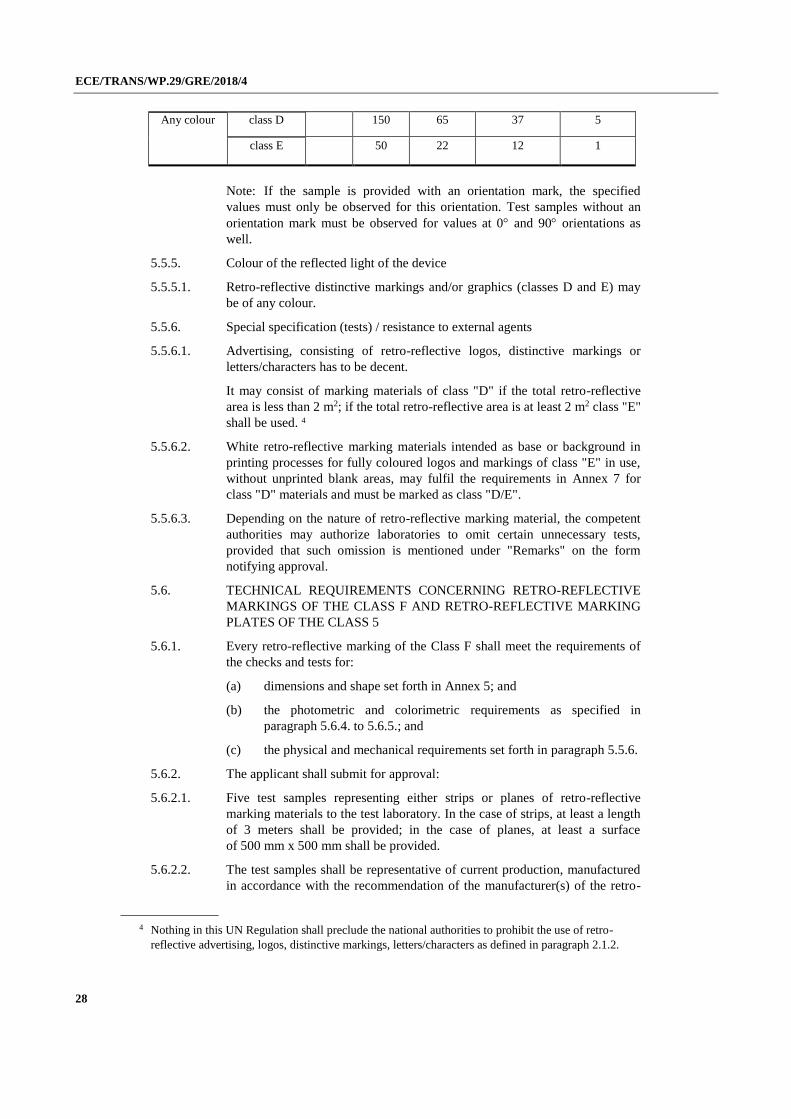
Table 10: Photometric specifications for distinctive markings or graphics of
class D and class E: Maximum values for the Coefficient of Retro-reflection
R' [cd∙m-²∙lx-1]
Observation angle α [°]
Entrance Angle β (°)
α = 0,33 (20')
β1
0
0
0
0
β2
5
30
40
60
2 Test samples of retro-reflective marking materials shall be applied to edged and degreased aluminium
panels of 2 mm thickness and shall be conditioned for 24 hours at 23°C ± 2°C at 50% ± 5% relative
humidity prior to testing.
3 Test samples of retro-reflective marking materials shall be applied to edged and degreased aluminium
panels of 2 mm thickness and shall be conditioned for 24 hours at 23°C ± 2°C at 50% ± 5% relative
humidity prior to testing.
ECE/TRANS/WP.29/GRE/2018/4
28
Any colour class D 150 65 37 5
class E 50 22 12 1
Note: If the sample is provided with an orientation mark, the specified
values must only be observed for this orientation. Test samples without an
orientation mark must be observed for values at 0 and 90 orientations as
well.
5.5.5. Colour of the reflected light of the device
5.5.5.1. Retro-reflective distinctive markings and/or graphics (classes D and E) may
be of any colour.
5.5.6. Special specification (tests) / resistance to external agents
5.5.6.1. Advertising, consisting of retro-reflective logos, distinctive markings or
letters/characters has to be decent.
It may consist of marking materials of class "D" if the total retro-reflective
area is less than 2 m2; if the total retro-reflective area is at least 2 m2 class "E"
shall be used. 4
5.5.6.2. White retro-reflective marking materials intended as base or background in
printing processes for fully coloured logos and markings of class "E" in use,
without unprinted blank areas, may fulfil the requirements in Annex 7 for
class "D" materials and must be marked as class "D/E".
5.5.6.3. Depending on the nature of retro-reflective marking material, the competent
authorities may authorize laboratories to omit certain unnecessary tests,
provided that such omission is mentioned under "Remarks" on the form
notifying approval.
5.6. TECHNICAL REQUIREMENTS CONCERNING RETRO-REFLECTIVE
MARKINGS OF THE CLASS F AND RETRO-REFLECTIVE MARKING
PLATES OF THE CLASS 5
5.6.1. Every retro-reflective marking of the Class F shall meet the requirements of
the checks and tests for:
(a) dimensions and shape set forth in Annex 5; and
(b) the photometric and colorimetric requirements as specified in
paragraph 5.6.4. to 5.6.5.; and
(c) the physical and mechanical requirements set forth in paragraph 5.5.6.
5.6.2. The applicant shall submit for approval:
5.6.2.1. Five test samples representing either strips or planes of retro-reflective
marking materials to the test laboratory. In the case of strips, at least a length
of 3 meters shall be provided; in the case of planes, at least a surface
of 500 mm x 500 mm shall be provided.
5.6.2.2. The test samples shall be representative of current production, manufactured
in accordance with the recommendation of the manufacturer(s) of the retro-
4 Nothing in this UN Regulation shall preclude the national authorities to prohibit the use of retro-
reflective advertising, logos, distinctive markings, letters/characters as defined in paragraph 2.1.2.
ECE/TRANS/WP.29/GRE/2018/4
29
reflective marking materials.5
The samples shall be tested in the chronological order indicated in paragraph
5.6.4.
5.6.3. Test procedure
Every retro-reflective marking of the Class F and Class 5 shall meet the
requirements of the checks and tests described in paragraphs 5.6.4. and 5.6.5.
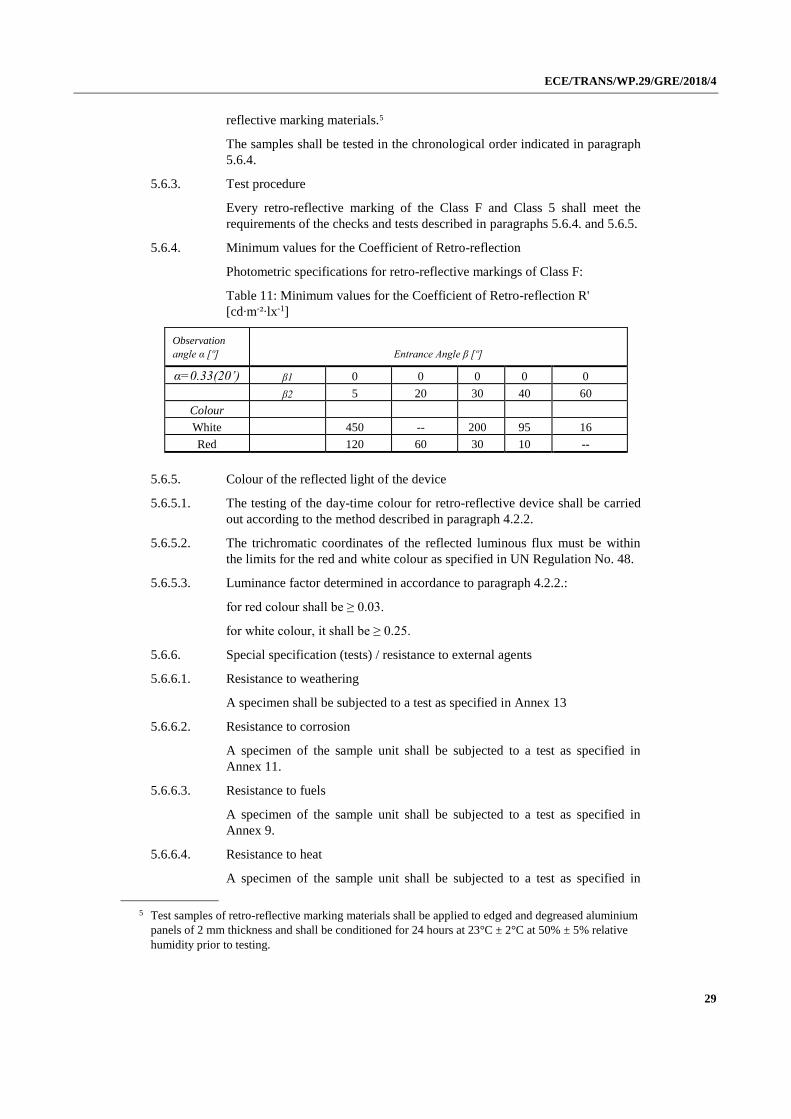
5.6.4. Minimum values for the Coefficient of Retro-reflection
Photometric specifications for retro-reflective markings of Class F:
Table 11: Minimum values for the Coefficient of Retro-reflection R'
[cd∙m-²∙lx-1]
5.6.5. Colour of the reflected light of the device
5.6.5.1. The testing of the day-time colour for retro-reflective device shall be carried
out according to the method described in paragraph 4.2.2.
5.6.5.2. The trichromatic coordinates of the reflected luminous flux must be within
the limits for the red and white colour as specified in UN Regulation No. 48.
5.6.5.3. Luminance factor determined in accordance to paragraph 4.2.2.:
for red colour shall be ≥ 0.03.
for white colour, it shall be ≥ 0.25.
5.6.6. Special specification (tests) / resistance to external agents
5.6.6.1. Resistance to weathering
A specimen shall be subjected to a test as specified in Annex 13
5.6.6.2. Resistance to corrosion
A specimen of the sample unit shall be subjected to a test as specified in
Annex 11.
5.6.6.3. Resistance to fuels
A specimen of the sample unit shall be subjected to a test as specified in
Annex 9.
5.6.6.4. Resistance to heat
A specimen of the sample unit shall be subjected to a test as specified in
5 Test samples of retro-reflective marking materials shall be applied to edged and degreased aluminium
panels of 2 mm thickness and shall be conditioned for 24 hours at 23°C ± 2°C at 50% ± 5% relative
humidity prior to testing.
Observation
angle α [º] Entrance Angle β [º]
α=0.33(20’) β1 0 0 0 0 0
β2 5 20 30 40 60
Colour
White 450 -- 200 95 16
Red 120 60 30 10 --
ECE/TRANS/WP.29/GRE/2018/4
30
Annex 6.
5.6.6.5. Resistance to cleaning
A specimen of the sample unit shall be subjected to a test as specified in
Annex 15.
5.6.7. Stability of photometric properties
A specimen of the sample unit shall be subjected to a test as specified in
Annex 14.
5.6.8. Resistance to penetration of water
A specimen of the sample unit shall be subjected to a test as specified in
Annex 7.
5.6.9. Bonding strength (in the case of adhesive materials)
A specimen of the sample unit shall be subjected to a test as specified in
Annex 16.
5.6.10. Flexing
For samples that are to be adhered to a flexible substrate, i.e. tarpaulin, the
following shall apply:
A specimen of the sample unit shall be subjected to a test as specified in
Annex 17.
5.6.11. In the case of Plates:
A specimen of a complete plate shall be subjected to a test of rigidity of
plates as specified in Annex 19.
5.7. TECHNICAL REQUIREMENTS CONCERNING RETRO-REFLECTIVE
MARKINGS PLATES OF THE CLASSES 1, 2, 3 AND 4
5.7.1. Retro-reflective devices of this paragraph must satisfy the conditions as to
(a) dimensions and shape set forth in Annexes 5, and
(b) the photometric and colorimetric as specified in paragraphs 5.7.4. to
5.7.5. and
(c) the physical and mechanical requirements set forth in paragraph 5.7.6.
5.7.2. The applicant shall submit for approval:
5.7.2.1. Two large chevron rear marking plates for trucks and tractors and two large
rear marking plates for trailers and semi-trailers (or their equivalent in
smaller plates) shall be supplied to the testing laboratory for the various tests
to be conducted.
5.7.2.2. The test samples shall be representative of current production, fabricated in
accordance with the recommendations of the manufacturer of the retro-
reflective or retro-reflective/fluorescent materials or devices.
The samples shall be tested in the chronological order indicated in paragraph
5.7.3.
5.7.3. Test procedure
Every retro-reflective marking Plate of the classes 1, 2, 3 and 4: shall meet
the requirements of the checks and tests described in Annex 5.
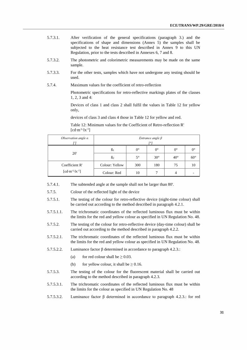
ECE/TRANS/WP.29/GRE/2018/4
31
5.7.3.1. After verification of the general specifications (paragraph 3.) and the
specifications of shape and dimensions (Annex 5) the samples shall be
subjected to the heat resistance test described in Annex 9 to this UN
Regulation, prior to the tests described in Annexes 6, 7 and 8.
5.7.3.2. The photometric and colorimetric measurements may be made on the same
sample.
5.7.3.3. For the other tests, samples which have not undergone any testing should be
used.
5.7.4. Maximum values for the coefficient of retro-reflection
Photometric specifications for retro-reflective markings plates of the classes
1, 2, 3 and 4:
Devices of class 1 and class 2 shall fulfil the values in Table 12 for yellow
only,
devices of class 3 and class 4 those in Table 12 for yellow and red.
Table 12: Minimum values for the Coefficient of Retro-reflection R'
[cd∙m-²∙lx-1]
Observation angle α
[']
Entrance angle β
[°]
20' ß1 0° 0° 0° 0°
ß2 5° 30° 40° 60°
Coefficient R'
[cd∙m-²∙lx-1]
Colour: Yellow 300 180 75 10
Colour: Red 10 7 4 -
5.7.4.1. The subtended angle at the sample shall not be larger than 80'.
5.7.5. Colour of the reflected light of the device
5.7.5.1. The testing of the colour for retro-reflective device (night-time colour) shall
be carried out according to the method described in paragraph 4.2.1.
5.7.5.1.1. The trichromatic coordinates of the reflected luminous flux must be within
the limits for the red and yellow colour as specified in UN Regulation No. 48.
5.7.5.2. The testing of the colour for retro-reflective device (day-time colour) shall be
carried out according to the method described in paragraph 4.2.2.
5.7.5.2.1. The trichromatic coordinates of the reflected luminous flux must be within
the limits for the red and yellow colour as specified in UN Regulation No. 48.
5.7.5.2.2. Luminance factor β determined in accordance to paragraph 4.2.3.:
(a) for red colour shall be ≥ 0.03.
(b) for yellow colour, it shall be ≥ 0.16.
5.7.5.3. The testing of the colour for the fluorescent material shall be carried out
according to the method described in paragraph 4.2.3.
5.7.5.3.1. The trichromatic coordinates of the reflected luminous flux must be within
the limits for the colour as specified in UN Regulation No. 48
5.7.5.3.2. Luminance factor β determined in accordance to paragraph 4.2.3.: for red
ECE/TRANS/WP.29/GRE/2018/4
32
colour shall be ≥ 0.3.
5.7.5.4. Rear marking plates for heavy vehicles and trailers shall be composed of
yellow retro-reflective and red retro-reflective or yellow retro-reflective and
red fluorescent materials or devices.
5.7.6. Special specification (tests) / resistance to external agents
5.7.6.1. Resistance to weathering
A specimen shall be subjected to a test as specified in Annex 13.
5.7.6.2. Resistance to corrosion
A specimen of the sample unit shall be subjected to a test as specified in
Annex 11.
5.7.6.3. Resistance to fuels
A specimen of the sample unit shall be subjected to a test as specified in
Annex 9.
5.7.6.4. Resistance to heat
A specimen of the sample unit shall be subjected to a test as specified in
Annex 6.
5.7.6.5. Resistance to cleaning
A specimen of the sample unit shall be subjected to a test as specified in
Annex 15.
5.7.6.6. Stability of photometric properties
A specimen of the sample unit shall be subjected to a test as specified in
Annex 14.
5.7.6.7. Resistance to penetration of water
A specimen of the sample unit shall be subjected to a test as specified in
Annex 7.
5.7.6.8. Bonding strength (in the case of adhesive materials)
A specimen of the sample unit shall be subjected to a test as specified in
Annex 16.
5.7.6.9. Flexing
5.7.6.9.1. For samples that are to be adhered to a flexible substrate, i.e. tarpaulin, the
following shall apply:
A specimen of the sample unit shall be subjected to a test as specified in
Annex 17.
5.7.6.9.2. In the case of Plates:
A specimen of a complete plate shall be subjected to a test of rigidity of
plates as specified in Annex 19.
5.7.7. Chronological order of tests for Classes 1, 2, 3 and 4
5.7.7.1. Two large chevron rear marking plates for trucks and tractors and two large
rear marking plates for trailers and semi-trailers (or their equivalent in
smaller plates) shall be supplied to the testing laboratory for the various tests
to be conducted.
ECE/TRANS/WP.29/GRE/2018/4
33
5.7.7.2. The test samples shall be representative of current production, fabricated in
accordance with the recommendations of the manufacturer of the retro-
reflective or retro-reflective/fluorescent materials or devices.
5.7.7.3. After verification of the general specifications (paragraph 6.) and the
specifications of shape and dimensions (Annex 5) the samples shall be
subjected to the heat resistance test described in Annex 9, prior to the tests
described in Annexes 6, 7 and 8.
5.7.7.4. The photometric and colorimetric measurements may be made on the same
sample.
5.7.7.5. For the other tests, samples which have not undergone any testing should be
used.
5.8. TECHNICAL REQUIREMENTS CONCERNING RETRO-REFLECTIVE
MARKING PLATES FOR SLOW MOVING VEHICLES OF THE CLASS
SMV
5.8.1. Retro-reflective devices of this paragraph must satisfy the conditions as to
(a) dimensions and shape set forth in in Annexes 8; and
(b) the photometric and colorimetric as specified in paragraphs 4.8.4. to
4.8.5.; and
(c) the physical and mechanical requirements set forth in Annexes 9, 11
to 13.
5.8.2. The applicant shall submit for approval:
5.8.2.1. Five SMV rear marking plates shall be supplied to the testing laboratory for
the various tests to be conducted.
5.8.2.2. The test samples shall be representative of current production, fabricated in
accordance with the recommendations of the manufacturer(s) of the retro-
reflective and fluorescent (class 1) or retro-reflective only (class 2).
The samples shall be tested in the chronological order indicated in paragraph
4.8.7.
5.8.3. Test procedure
5.8.3.1. Every Retro-reflective Marking Plate for slow moving vehicles of the Class
SMV shall meet the requirements of the checks and tests described in
Annex 5.
5.8.3.2. After verification of the general specifications (paragraph 5.) and the
specifications of shape and dimensions (Annex 5) four samples shall be
subjected to the heat resistance test described in Annex 9 to this UN
Regulation, prior to the tests described in Annexes 6, 7 and 8. The fifth
sample shall be kept for reference purposes during the test procedures.
5.8.3.3. The photometric and colorimetric measurements may be made on the same
sample.
5.8.3.4. For the other tests, samples which have not undergone any testing should be
used.
5.8.4. Maximum values for the coefficient of retro-reflection
Photometric specifications for retro-reflective markings plates for slow
moving vehicles of the Class SMV
ECE/TRANS/WP.29/GRE/2018/4
34
5.8.4.1. When measured as described in paragraph 3., the coefficient of retro-
reflection R' in candelas per m2 per lux (cd/m2/lux) of the entire red retro-
reflective area in new condition shall be at least as indicated in Table 13.
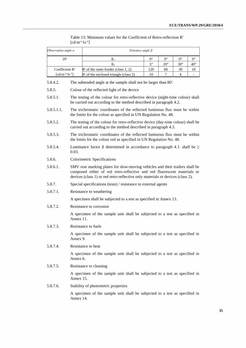
ECE/TRANS/WP.29/GRE/2018/4
35
Table 13: Minimum values for the Coefficient of Retro-reflection R'
[cd∙m-²∙lx-1]
Observation angle α Entrance angle β
20' ß1 0° 0° 0° 0°
ß2 5° 20° 30° 40°
Coefficient R'
[cd∙m-²∙lx-1]
R' of the outer border (class 1, 2) 120 60 30 10
R' of the enclosed triangle (class 2) 10 7 4 -
5.8.4.2. The subtended angle at the sample shall not be larger than 80'.
5.8.5. Colour of the reflected light of the device
5.8.5.1. The testing of the colour for retro-reflective device (night-time colour) shall
be carried out according to the method described in paragraph 4.2.
5.8.5.1.1. The trichromatic coordinates of the reflected luminous flux must be within
the limits for the colour as specified in UN Regulation No. 48.
5.8.5.2. The testing of the colour for retro-reflective device (day-time colour) shall be
carried out according to the method described in paragraph 4.3.
5.8.5.3. The trichromatic coordinates of the reflected luminous flux must be within
the limits for the colour red as specified in UN Regulation No. 48.
5.8.5.4. Luminance factor β determined in accordance to paragraph 4.3. shall be ≥
0.03.
5.8.6. Colorimetric Specifications
5.8.6.1. SMV rear marking plates for slow-moving vehicles and their trailers shall be
composed either of red retro-reflective and red fluorescent materials or
devices (class 1) or red retro-reflective only materials or devices (class 2).
5.8.7. Special specifications (tests) / resistance to external agents
5.8.7.1. Resistance to weathering
A specimen shall be subjected to a test as specified in Annex 13.
5.8.7.2. Resistance to corrosion
A specimen of the sample unit shall be subjected to a test as specified in
Annex 11.
5.8.7.3. Resistance to fuels
A specimen of the sample unit shall be subjected to a test as specified in
Annex 9.
5.8.7.4. Resistance to heat
A specimen of the sample unit shall be subjected to a test as specified in
Annex 6.
5.8.7.5. Resistance to cleaning
A specimen of the sample unit shall be subjected to a test as specified in
Annex 15.
5.8.7.6. Stability of photometric properties
A specimen of the sample unit shall be subjected to a test as specified in
Annex 14.
ECE/TRANS/WP.29/GRE/2018/4
36
5.8.7.7. Resistance to penetration of water
A specimen of the sample unit shall be subjected to a test as specified in
Annex 7.
5.8.7.8. Bonding strength (in the case of adhesive materials)
A specimen of the sample unit shall be subjected to a test as specified in
Annex 16.
5.8.7.9. Flexing
5.8.7.9.1. For samples that are to be adhered to a flexible substrate, i.e. tarpaulin, the
following shall apply:
A specimen of the sample unit shall be subjected to a test as specified in
Annex 17.
5.8.7.9.2. In the case of Plates:
A specimen of a complete plate shall be subjected to a test of rigidity of
plates as specified in Annex 19.
5.8.8. Chronological order
5.8.8.1. Five SMV rear marking plates shall be supplied to the testing laboratory for
the various tests to be conducted.
5.8.8.2. The test samples shall be representative of current production, fabricated in
accordance with the recommendations of the manufacturer(s) of the retro-
reflective and fluorescent (class 1) or retro-reflective only (class 2).
5.8.8.3. After verification of the general specifications (paragraph 6.) and the
specifications of shape and dimensions (Annex 5) four samples shall be
subjected to the heat resistance test described in Annex 9, prior to the tests
described in Annexes 6, 7 and 8. The fifth sample shall be kept for reference
purposes during the test procedures.
5.8.8.4. The photometric and colorimetric measurements may be made on the same
sample.
5.8.8.5. For the other tests, samples which have not undergone any testing should be
used.
5.9. TECHNICAL REQUIREMENTS CONCERNING ADVANCE WARNING
TRIANGLES OF TYPE 1 AND 2
5.9.1. Retro-reflective devices of this paragraph must satisfy the conditions as to
(a) dimensions and shape set forth in Annexes 8; and
(b) the photometric and colorimetric as specified in paragraphs 5.9.4. to
5.9.5.; and
(c) the physical and mechanical requirements set forth in Annexes 9, 11
to 13.
5.9.2. The applicant shall submit for approval:
5.9.2.1. Four samples of the advance warning triangle and at least two protective
covers if the advance warning triangles are to be supplied with protective
covers;
5.9.2.2. Two samples of the fluorescent or fluorescent retro-reflecting material in
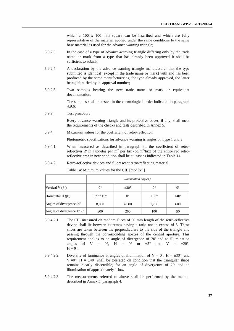
ECE/TRANS/WP.29/GRE/2018/4
37
which a 100 x 100 mm square can be inscribed and which are fully
representative of the material applied under the same conditions to the same
base material as used for the advance warning triangle;
5.9.2.3. In the case of a type of advance-warning triangle differing only by the trade
name or mark from a type that has already been approved it shall be
sufficient to submit:
5.9.2.4. A declaration by the advance-warning triangle manufacturer that the type
submitted is identical (except in the trade name or mark) with and has been
produced by the same manufacturer as, the type already approved, the latter
being identified by its approval number;
5.9.2.5. Two samples bearing the new trade name or mark or equivalent
documentation.
The samples shall be tested in the chronological order indicated in paragraph
4.9.6.
5.9.3. Test procedure
Every advance warning triangle and its protective cover, if any, shall meet
the requirements of the checks and tests described in Annex 5.
5.9.4. Maximum values for the coefficient of retro-reflection
Photometric specifications for advance warning triangles of Type 1 and 2
5.9.4.1. When measured as described in paragraph 3., the coefficient of retro-
reflection R' in candelas per m2 per lux (cd/m2/lux) of the entire red retro-
reflective area in new condition shall be at least as indicated in Table 14.
5.9.4.2. Retro-reflective devices and fluorescent retro-reflecting material.
Table 14: Minimum values for the CIL [mcd.lx-1]
Illumination angles β
Vertical V (β1) 0° ±20° 0° 0°
Horizontal H (β2) 0° or ±5° 0° ±30° ±40°
Angles of divergence 20' 8,000 4,000 1,700 600
Angles of divergence 1°30' 600 200 100 50
5.9.4.2.1. The CIL measured on random slices of 50 mm length of the retro-reflective
device shall lie between extremes having a ratio not in excess of 3. These
slices are taken between the perpendiculars to the side of the triangle and
passing through the corresponding apexes of the central aperture. This
requirement applies to an angle of divergence of 20' and to illumination
angles of V = 0°, H = 0° or ±5° and V = ±20°,
H = 0°.
5.9.4.2.2. Diversity of luminance at angles of illumination of V = 0°, H = ±30°, and
V =0°, H = ±40° shall be tolerated on condition that the triangular shape
remains clearly discernible, for an angle of divergence of 20' and an
illumination of approximately 1 lux.
5.9.4.2.3. The measurements referred to above shall be performed by the method
described in Annex 5, paragraph 4.
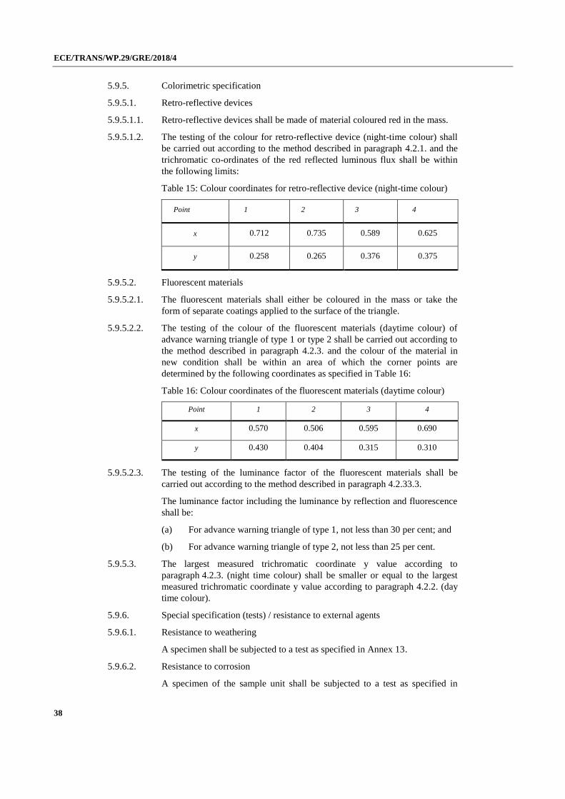
ECE/TRANS/WP.29/GRE/2018/4
38
5.9.5. Colorimetric specification
5.9.5.1. Retro-reflective devices
5.9.5.1.1. Retro-reflective devices shall be made of material coloured red in the mass.
5.9.5.1.2. The testing of the colour for retro-reflective device (night-time colour) shall
be carried out according to the method described in paragraph 4.2.1. and the
trichromatic co-ordinates of the red reflected luminous flux shall be within
the following limits:
Table 15: Colour coordinates for retro-reflective device (night-time colour)
Point 1 2 3 4
x 0.712 0.735 0.589 0.625
y 0.258 0.265 0.376 0.375
5.9.5.2. Fluorescent materials
5.9.5.2.1. The fluorescent materials shall either be coloured in the mass or take the
form of separate coatings applied to the surface of the triangle.
5.9.5.2.2. The testing of the colour of the fluorescent materials (daytime colour) of
advance warning triangle of type 1 or type 2 shall be carried out according to
the method described in paragraph 4.2.3. and the colour of the material in
new condition shall be within an area of which the corner points are
determined by the following coordinates as specified in Table 16:
Table 16: Colour coordinates of the fluorescent materials (daytime colour)
Point 1 2 3 4
x 0.570 0.506 0.595 0.690
y 0.430 0.404 0.315 0.310
5.9.5.2.3. The testing of the luminance factor of the fluorescent materials shall be
carried out according to the method described in paragraph 4.2.33.3.
The luminance factor including the luminance by reflection and fluorescence
shall be:
(a) For advance warning triangle of type 1, not less than 30 per cent; and
(b) For advance warning triangle of type 2, not less than 25 per cent.
5.9.5.3. The largest measured trichromatic coordinate y value according to
paragraph 4.2.3. (night time colour) shall be smaller or equal to the largest
measured trichromatic coordinate y value according to paragraph 4.2.2. (day
time colour).
5.9.6. Special specification (tests) / resistance to external agents
5.9.6.1. Resistance to weathering
A specimen shall be subjected to a test as specified in Annex 13.
5.9.6.2. Resistance to corrosion
A specimen of the sample unit shall be subjected to a test as specified in
ECE/TRANS/WP.29/GRE/2018/4
39
Annex 11.
5.9.6.3. Resistance to fuels
A specimen of the sample unit shall be subjected to a test as specified in
Annex 9.
5.9.6.4. Resistance to heat
A specimen of the sample unit shall be subjected to a test as specified in
Annex 6.
5.9.6.5. Resistance to cleaning
A specimen of the sample unit shall be subjected to a test as specified in
Annex 15.
5.9.6.6. Stability of photometric properties
A specimen of the sample unit shall be subjected to a test as specified in
Annex 14.
5.9.6.7. Resistance to penetration of water
A specimen of the sample unit shall be subjected to a test as specified in
Annex 7.
5.9.6.8. Bonding strength (in the case of adhesive materials)
A specimen of the sample unit shall be subjected to a test as specified in
Annex 16.
5.9.6.9. Flexing
5.9.6.9.1. For samples that are to be adhered to a flexible substrate, i.e. tarpaulin, the
following shall apply:
A specimen of the sample unit shall be subjected to a test as specified in
Annex 17.
5.9.6.9.2. Wind test
A specimen of a complete plate shall be subjected to a test of rigidity of
plates as specified in Annex 10
5.9.7. Chronological order
5.9.7.1. General
5.9.7.1.1. The applicant shall submit samples, as mentioned in paragraphs 3.1, for
approval.
5.9.7.1.2. After verification of the general specifications Annex 4 (paragraph 6.) and
the specifications of shape and dimensions Annex 5 (paragraph 7.1.), all
samples shall be subjected to the heat resistance test Annex 6 (paragraph 7.)
and examined after at least one hour of rest.
5.9.7.1.3. The CIL value of the four samples of the advance warning triangles
submitted is measured at an observation angle of 20' and at an illumination
angle with the components V = 0°, H = ±5°; this test is carried out in
accordance with the method described in paragraph 4.
5.9.7.1.4. The two samples with the smallest and the largest CIL value in the tests
according to paragraph 1.3. shall be subsequently subjected to the following
tests:
ECE/TRANS/WP.29/GRE/2018/4
40
5.9.7.1.4.1. Measurement of the values of the CIL in respect of the observation and
illumination angles referred to in paragraph 5.9.4.2. according to the method
described in paragraph 4.
5.9.7.1.4.2. Testing of the colour of the retro-reflected light according to paragraph 4.2.
on the sample with the highest CIL concerned shall be examined.
5.9.7.1.4.3. Test of clearance to ground according to Annex 20 paragraph 5.
5.9.7.1.4.4. Mechanical solidity test according to Annex 20 paragraph 6.
5.9.7.1.5. One sample other than those referred to in paragraph 5.9.7.1.1. shall be
subjected to the following tests:
5.9.7.1.5.1. Testing of resistance to penetration of water into the retro-reflective device
according to Annex 7 or if relevant, of the mirror-backed reverse side of the
retro-reflective device, according to Annex 7.
5.9.7.1.6. The second sample, other than those referred to in paragraph 5.9.7.1.1., shall
be subjected to the following tests:
5.9.7.1.6.1. Water test according to Annex 7.
5.9.7.1.6.2. Testing of resistance to fuels according to Annex 9.
5.9.7.1.6.3. Test of stability against wind according to Annex 20.
5.9.7.1.7. After the tests specified in paragraph 5.9.7.14., the two samples submitted
according to paragraph 3.1 shall be subjected to the following tests:
5.9.7.1.7.1. Colour test according to paragraph 4.2.2.;
5.9.7.1.7.2. Test of the luminance factor according to paragraph 4.2.2.;
5.9.7.1.7.3. Test of weather resistance according to Annex 13.
ECE/TRANS/WP.29/GRE/2018/4
41
Annex 1
Communication
(Maximum format: A4 (210 x 297 mm))
1
concerning:2 Approval
Approval extended
Approval refused
Approval withdrawn
Production definitively discontinued
of a type of retro-reflective device
of a type of advance warning triangle
of a type of SMV rear marking plate
of a type of rear marking plate,
of retro-reflective markings of heavy and long vehicles and their trailers pursuant to UN
Regulation No. [RRD]
Class of the device: ……… [Change index: ……]
Approval No: ...... Extension No: ......
Unique Identifier (UI) (If applicable): … …
1. Trade name or mark of the retro-reflective device or marking material: ................
.................................................................................................................................
2. Manufacturer's name: ..............................................................................................
2.1. for the retro-reflecting type of device: .....................................................................
2.2. for the advance warning triangle .............................................................................
2.3. for the SMV rear marking plate type: ......................................................................
2.3.1. SMV rear marking plate class: ...............................................................................
1 Distinguishing number of the country which has granted/extended/refused/withdrawn approval (see
approval provisions in the Regulation).
2 Strike out what does not apply.
issued by: Name of administration:
......................................
......................................
......................................

ECE/TRANS/WP.29/GRE/2018/4
42
2.4. for the rear marking plate type: ...............................................................................
2.4.1. Rear marking plate class: ........................................................................................
2.5. Class of the marking material: .................................................................................
3. Name and address of the manufacturer: ..................................................................
4. If applicable, name and address of manufacturer's representative: ........................
.................................................................................................................................
5. Date on which the marking material was submitted for approval tests: ..................
6. Technical service responsible for carrying out the approval test: ...........................
7. Date of test report issued by the technical service:..................................................
8. Number of test report issued by the technical service: ............................................
9. Remarks: .................................................................................................................
10. Approval granted/refused/extended/withdrawn 2
11. Reason(s) for the extension (if applicable): .............................................................
.................................................................................................................................
12. Place: .......................................................................................................................
13. Date: ........................................................................................................................
14. Signature: ................................................................................................................
Name: ......................................................................................................................
15. Annexed is a list of documents making up the approval file, deposited with the
Competent Authority which granted approval; a copy can be obtained on request.
ECE/TRANS/WP.29/GRE/2018/4
43
Annex 2
Minimum requirements for conformity of production control procedures
1. GENERAL
1.1. The conformity requirements shall be considered satisfied from a mechanical
and geometric standpoint, if the differences do not exceed inevitable
manufacturing deviations within the requirements of this UN Regulation.
1.2. With respect to photometric performances, the conformity of mass-produced
retro-reflective devices shall not be contested if, when testing photometric
performances of any retro-reflective device chosen at random no measured
value deviates unfavourably by more than 20 per cent from the minimum
values prescribed in this UN Regulation.
1.3. The chromaticity coordinates shall be complied with.
2. MINIMUM REQUIREMENTS FOR VERIFICATION OF CONFORMITY
BY THE MANUFACTURER
For each type of retro-reflective device the holder of the approval mark shall
carry out at least the following tests, at appropriate intervals. The tests shall
be carried out in accordance with the provisions of this UN Regulation.
If any sampling shows non-conformity with regard to the type of test
concerned, further samples shall be taken and tested. The manufacturer shall
take steps to ensure the conformity of the production concerned.
2.1. Nature of tests
Tests of conformity in this UN Regulation shall cover the photometric and
colorimetric characteristics and the resistance to penetration of water.
2.2. Methods used in tests
2.2.1. Tests shall generally be carried out in accordance with the methods set out in
this UN Regulation.
2.2.2. In any test of conformity carried out by the manufacturer, equivalent methods
may be used with the consent of the Type Approval Authority. The
manufacturer is responsible for proving that the applied methods are
equivalent to those laid down in this UN Regulation.
2.2.3. The application of paragraphs 2.2.1. and 2.2.2. requires regular calibration of
test apparatus and its correlation with measurements made by a competent
authority.
2.2.4. In all cases the reference methods shall be those of this UN Regulation,
particularly for the purpose of administrative verification and sampling.
2.3. Nature of sampling
Samples of retro-reflective devices shall be selected at random from the
production of a uniform batch. A uniform batch means a set of retro-
reflective devices of the same type, defined according to the production
methods of the manufacturer.
ECE/TRANS/WP.29/GRE/2018/4
44
The assessment shall in general cover series production from individual
factories. However, a manufacturer may group together records concerning
the same type from several factories, provided these operate under the same
quality system and quality management.
2.4. Measured and recorded photometric characteristics
The sampled retro-reflective device shall be subjected to photometric
measurements at the points and the chromaticity coordinates provided for in
the Regulation.
2.5. Criteria governing acceptability
The manufacturer is responsible for carrying out a statistical study of the test
results and for defining, in agreement with the Type Approval Authority,
criteria governing the acceptability of his products in order to meet the
specifications laid down for the verification of conformity of products in
paragraph 3.5.1. of this UN Regulation. The criteria governing the
acceptability shall be such that, with a confidence level of 95 per cent, the
minimum probability of passing a spot check in accordance with Annex 18
(first sampling) would be 0.95.
ECE/TRANS/WP.29/GRE/2018/4
45
Annex 3
Minimum requirements for sampling by an inspector
1. GENERAL
1.1. The conformity requirements shall be considered satisfied from a mechanical
and a geometric standpoint, in accordance with the requirements of this UN
Regulation, if any, if the differences do not exceed inevitable manufacturing
deviations.
1.2. With respect to photometric performance, the conformity of mass-produced
retro-reflective devices shall not be contested if, when testing photometric
performances of any retro-reflective device chosen at random:
1.2.1. No measured value deviates unfavourably by more than 20 per cent from the
minimum values prescribed in this UN Regulation.
1.2.2. Retro-reflective devices with apparent defects are disregarded.
1.3. The chromaticity coordinates shall be complied with.
2. FIRST SAMPLING
In the first sampling four retro-reflective devices are selected at random. The
first sample of two is marked A, the second sample of two is marked B.
2.1. The conformity of mass-produced retro-reflective devices shall not be
contested if the deviation of any specimen of samples A and B (all four retro-
reflective devices) is not more than 20 per cent.
In the case, that the deviation of both retro-reflective devices of sample A is
not more than 0 per cent, the measurement can be closed.
2.2. The conformity of mass-produced retro-reflective devices shall be contested
if the deviation of at least one specimen of samples A or B is more than 20
per cent.
The manufacturer shall be requested to bring his production in line with the
requirements (alignment) and a repeated sampling according to paragraph 3.
below shall be carried out within two months' time after the notification. The
samples A and B shall be retained by the Technical Service until the entire
CoP process is finished.
3. FIRST REPEATED SAMPLING
A sample of four retro-reflective devices is selected at random from stock
manufactured after alignment.
The first sample of two is marked C, the second sample of two is marked D.
3.1. The conformity of mass-produced retro-reflective devices shall not be
contested if the deviation of any specimen of samples C and D (all four retro-
reflective devices) is not more than 20 per cent.
In the case, that the deviation of both retro-reflective devices of sample C is
not more than 0 per cent, the measurement can be closed.
3.2. The conformity of mass-produced retro-reflective devices shall be contested
if the deviation of at least:
ECE/TRANS/WP.29/GRE/2018/4
46
3.2.1. one specimen of samples C or D is more than 20 per cent but the deviation of
all specimen of these samples is not more than 30 per cent.
The manufacturer shall be requested again to bring his production in line with
the requirements (alignment).
A second repeated sampling according to paragraph 4. shall be carried out
within two months' time after the notification. The samples C and D shall be
retained by the Technical Service until the entire CoP process is finished.
3.2.2. one specimen of samples C and D is more than 30 per cent:
In this case the approval shall be withdrawn and paragraph 5. shall be
applied.
4. SECOND REPEATED SAMPLING
A sample of four retro-reflective devices is selected at random from stock
manufactured after alignment.
The first sample of two is marked E, the second sample of two is marked F.
4.1. The conformity of mass-produced retro-reflective devices shall not be
contested if the deviation of any specimen of samples E and F (all four retro-
reflective devices) is not more than 20 per cent. In the case, that the deviation
of both retro-reflective devices of sample E is not more than 0 per cent the
measurement can be closed.
4.2. The conformity of mass-produced retro-reflective devices shall be contested
if the deviation of at least one specimen of samples E or F is more than 20
per cent.
In this case the approval shall be withdrawn and paragraph 5. shall be
applied.
5. APPROVAL WITHDRAWN
Approval shall be withdrawn according to paragraph 3.6. of this UN
Regulation.
6. RESISTANCE TESTS
6.1. One of the retro-reflective devices of sample A after the sampling procedure
in paragraph 2. shall be tested according to the procedure described in
paragraph 1. of Annex 7 or, in the case of the Advance Warning Triangle, the
sample A shall be tested according to the procedure described in paragraph 2.
of Annex 7.
The retro-reflective devices shall be considered as acceptable if the test has
been passed. However, if the test on sample A is not complied with, the two
retro-reflective devices of sample B shall be subjected to the same procedure
and both shall pass the test.
6.2. Specimens of one of the rear marking plates of sample A after the sampling
procedure in paragraph 2., shall be tested according to the procedures
described in Annexes 6, 7, 9, 11, 13, 15, 16 and 18 to this UN Regulation.
The rear marking plate shall be considered acceptable if the tests were
passed.
However, if the tests on specimens of sample A did not pass the tests, the two
rear marking plates of sample B shall be subjected to the same procedure and
both shall pass the test.
ECE/TRANS/WP.29/GRE/2018/4
47
Annex 4
Photometric measurements of retro-reflective devices and marking materials
1. TEST PROCEDURES
1.1. When the CIL of a retro-reflective device is measured for an angle β of
V = H = 0°, it shall be ascertained whether any mirror effect is produced by
slightly turning the device. If there is any such effect, a reading shall be taken
with an angle β of V = ±5°, H = 0°. The position adopted shall be that
corresponding to the minimum CIL for one of these positions.
1.2. With an illumination angle β of V = H = 0°, or the angle specified in
paragraph 5. of this UN Regulation, and an angle of divergence of 20', retro-
reflective devices which are not marked "TOP" shall be rotated about their
axes of reference to the position of minimum CIL, which must conform to the
value specified in paragraph 5. of this UN Regulation. When the CIL is
measured for the other angles of illumination and divergence, the retro-
reflective device shall be placed in the position corresponding to this value of
ε. If the specified values are not attained, the device may be rotated about its
axis of reference ±5° from that position.
1.3. With an illumination angle β of V = H = 0°, or the angle specified in
paragraph 4. of this UN Regulation, and an angle of divergence of 20', retro-
reflective devices marked "TOP" shall be rotated about their axes ±5°. The
CIL must not fall below the prescribed value in any position assumed by the
device during this rotation.
1.4. If for the direction V = H = 0°, and for ε = 0° the CIL exceeds the specified
value by 50 per cent or more, all measurements for all angles of illumination
and divergence shall be made for ε = 0°.
2. DEFINITIONS
The definitions are explained by Figures A4-I to A4-V.
3. DIMENSIONAL AND PHYSICAL SPECIFICATIONS FOR THE
PHOTOMETRY OF RETRO-REFLECTIVE DEVICES
3.1. The CIE-angular system as shown in Figure A4-I shall be used.
An adequate support (goniometer) is demonstrated in Figure A4-II.
3.2. For testing the retro-reflection the retro-reflective devices shall be
illuminated with a CIE Standard Illuminant A (ISO 11664-2:2007(E)/CIE S
014-2/E:2006) and measured as described in Annex 4.
3.3. The measuring geometry is described in Figure A4-I and the following limits
are set up:
Angular diameter of the source - 10'
Angular diameter of the measuring device - 10'
Angular diameter of the illuminated area - 80'
3.4. During photometric measurements, stray reflections should be avoided by
appropriate masking.
ECE/TRANS/WP.29/GRE/2018/4
48
3.5. The measuring distance shall be chosen in such an order that at least the
limits for the angles , and given in Figure A4-IV are respected, but not
lower than 10 m or its optical equivalent.
The retro-reflection values shall be determined by means of a measuring
geometry as described above with the retro–reflecting device set up to a
distance of at least 10m forward of the centre of reference of each retro–
reflecting device perpendicular to the measurement axis from the origin of
the gonio(photo)meter system.
3.6. The illuminance at the retro-reflective device
The illuminance over the useful area of the retro-reflective device, measured
perpendicular to the incident light shall be sufficiently uniform. A check on
this condition requires a measuring element, the sensitive area of which is not
greater than one-tenth of the area to be examined. The variation in the value
of the illuminance shall then comply with the condition:
05.1valueimummin
valueimummax
3.7. The colour temperature and the spectral distribution of the source
The source used for illuminating the retro-reflective device shall as faithfully
as possible represent the CIE Illuminant A, both as regards colour
temperature and spectral power distribution.
3.8. The photometer head (measuring element)
3.8.1. The photometer head shall be corrected to the spectral luminous efficiency
for the CIE standard photometric observer in photopic vision.
3.8.2. The device shall not show a perceptible change in local sensitivity within the
area of its aperture; otherwise suitable provisions shall be added, e.g. the
application of a diffusing window at a certain distance in front of the
sensitive surface.
3.8.3. Experience has shown that non-linearity of photometer heads may be a
problem with the very small light quantities which are the rule in the
photometry of retro-reflective devices A check at comparable illuminance
levels on the photometer head is recommended.
3.9. The influence of a regular reflection
The amount and distribution of the regular reflection from the surface of the
retro-reflector depends on the flatness and the gloss of the surface. In general,
regular reflection is best avoided when the reference axis is placed so that the
regular reflection is directed on the opposite side of the source from the
photometer head (for example with 1 = -5°).
4. MEASUREMENT PRECAUTIONS IN THE PHOTOMETRY OF RETRO-
REFLECTION
4.1. Residual and stray light
4.1.1. Since very low light levels are to be measured special precautions are needed
to minimize errors due to stray light. The background to the sample and the
framework of the sample holder should be matt black and the field of view of
ECE/TRANS/WP.29/GRE/2018/4
49
the photometer head and the spread of light from both the sample and the
source should each be restricted as much as possible.
4.1.2. Reflections from the floor and walls which occur over the relatively long test
distances used shall be screened from both the sample and the photometer
head by baffles. The importance of looking from the photometer head to
check for sources of stray light cannot be over emphasized.
4.1.3. A valuable aid to reducing the amount of stray light in the laboratory is to use
a slide projector type of optical system for the light source. With this, an iris
diaphragm or suitable sized apertures may be used in the optical system to
restrict the illuminated area at the sample to the minimum size needed to
provide uniform illuminance over the sample.
4.1.4. Residual stray light should always be allowed for by measuring it when the
sample is covered by an opaque matt black surface, zigzag folded black paper
of the same size and shape or a specular black surface suitably oriented with
a light trap. This value should be subtracted from that measured on the retro-
reflective device
4.2. Stability of the apparatus
4.2.1. The light source and photometer head should remain stable throughout the
period of the test. Since the sensitivity and the adaptation to the V ()
function of most photometer heads change with temperature, the laboratory
ambient temperature should not vary significantly during this period.
Sufficient time should always be allowed for the apparatus to stabilize before
commencing measurements.
4.2.2. The power supply to the light source should be adequately stabilized so that
the luminous intensity of the lamp can be maintained throughout the test to
within the required accuracy for the work.
4.2.3. A useful check on the overall stability of the reflex photometer during a
series of tests is to make periodic measurements of CIL values of a stable
reference standard.
4.2.4. Another technique is to incorporate in the apparatus an auxiliary detector to
check or monitor the output of the light source. Although the output from the
auxiliary detector can be checked for any change in reading, a useful
refinement is to use the output to alter electronically the sensitivity of the
main reflex photometer head and compensate automatically for changes in
the light output of the source.
4.3. Description of Goniometer
A goniometer as defined in paragraph 2.4. of this UN Regulation, which can
be used in making retro-reflection measurements in the CIE geometry is
illustrated in Figure A4-V. In this illustration, the photometer head (O) is
arbitrarily shown to be vertically above the source (I). The first axis is shown
to be fixed and horizontal and is situated perpendicular to the observation
half-plane. Any arrangement of the components which is equivalent to the
one shown can be used.
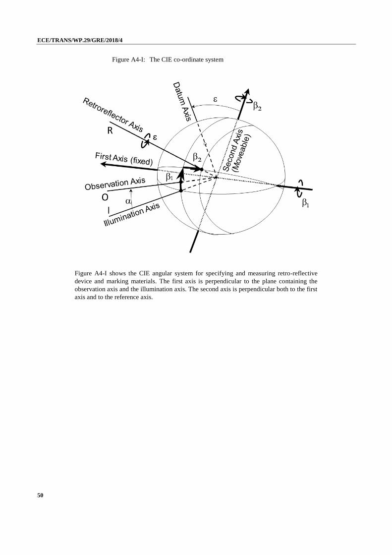
ECE/TRANS/WP.29/GRE/2018/4
50
Figure A4-I: The CIE co-ordinate system
Figure A4-I shows the CIE angular system for specifying and measuring retro-reflective
device and marking materials. The first axis is perpendicular to the plane containing the
observation axis and the illumination axis. The second axis is perpendicular both to the first
axis and to the reference axis.
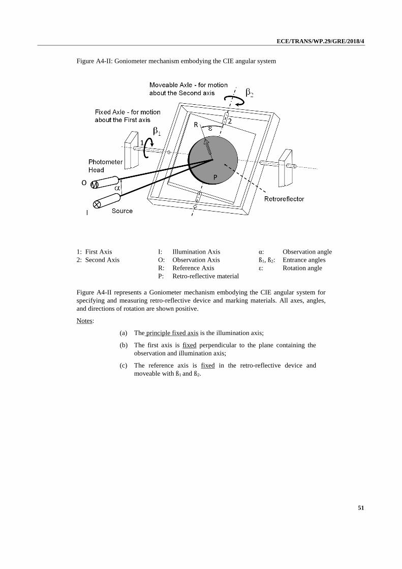
ECE/TRANS/WP.29/GRE/2018/4
51
Figure A4-II: Goniometer mechanism embodying the CIE angular system
1: First Axis I: Illumination Axis α: Observation angle
2: Second Axis O: Observation Axis ß1, ß2: Entrance angles
R: Reference Axis ε: Rotation angle
P: Retro-reflective material
Figure A4-II represents a Goniometer mechanism embodying the CIE angular system for
specifying and measuring retro-reflective device and marking materials. All axes, angles,
and directions of rotation are shown positive.
Notes:
(a) The principle fixed axis is the illumination axis;
(b) The first axis is fixed perpendicular to the plane containing the
observation and illumination axis;
(c) The reference axis is fixed in the retro-reflective device and
moveable with ß1 and ß2.
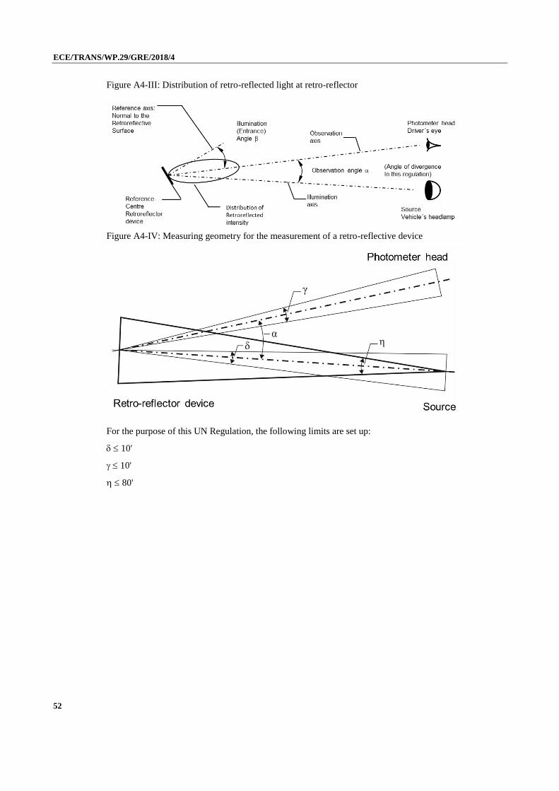
ECE/TRANS/WP.29/GRE/2018/4
52
Figure A4-III: Distribution of retro-reflected light at retro-reflector
Figure A4-IV: Measuring geometry for the measurement of a retro-reflective device
For the purpose of this UN Regulation, the following limits are set up:
10'
10'
80'
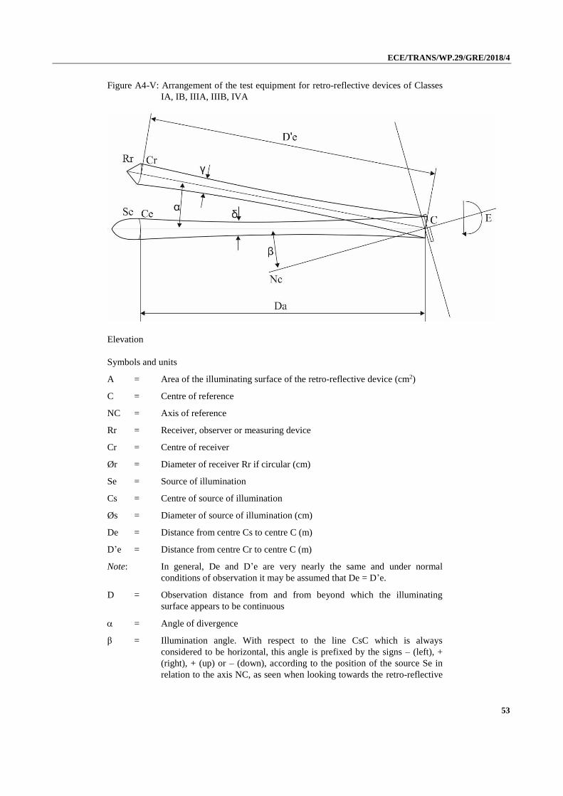
ECE/TRANS/WP.29/GRE/2018/4
53
Figure A4-V: Arrangement of the test equipment for retro-reflective devices of Classes
IA, IB, IIIA, IIIB, IVA
Elevation
Symbols and units
A = Area of the illuminating surface of the retro-reflective device (cm2)
C = Centre of reference
NC = Axis of reference
Rr = Receiver, observer or measuring device
Cr = Centre of receiver
Ør = Diameter of receiver Rr if circular (cm)
Se = Source of illumination
Cs = Centre of source of illumination
Øs = Diameter of source of illumination (cm)
De = Distance from centre Cs to centre C (m)
D’e = Distance from centre Cr to centre C (m)
Note: In general, De and D’e are very nearly the same and under normal
conditions of observation it may be assumed that De = D’e.
D = Observation distance from and from beyond which the illuminating
surface appears to be continuous
= Angle of divergence
β = Illumination angle. With respect to the line CsC which is always
considered to be horizontal, this angle is prefixed by the signs – (left), +
(right), + (up) or – (down), according to the position of the source Se in
relation to the axis NC, as seen when looking towards the retro-reflective
ECE/TRANS/WP.29/GRE/2018/4
54
device. For any direction defined by two angles, vertical and horizontal,
the vertical angle is always given first.
Γ = Angular diameter of the measuring device Rr as seen from point C
δ = Angular diameter of the source Se as seen from point C
ε = Angle of rotation. This angle is positive when the rotation is clockwise as
seen when looking towards the illuminating surface. If the retro-reflective
device is marked “TOP”, the position thus indicated is taken as the origin.
E = Illumination of the retro-reflective device (lux)
CIL = Coefficient of luminous intensity (millicandelas/lux)
Angles are expressed in degrees and minutes.
ECE/TRANS/WP.29/GRE/2018/4
55
Annex 5
Specifications of shape and dimensions
1. SHAPE AND DIMENSIONS OF RETRO-REFLECTIVE DEVICES IN
CLASS IA OR IB
1.1. The shape of the illuminating surfaces must be simple, and not easily
confused at normal observation distances, with a letter, a digit or a triangle.
1.2. The preceding paragraph 1.1. notwithstanding, a shape resembling the letters
or digits of simple form O, I, U or 8 is permissible.
2. SHAPE AND DIMENSIONS OF RETRO-REFLECTIVE DEVICES IN
CLASSES IIIA AND IIIB (SEE APPENDIX TO THIS ANNEX)
2.1. The illuminating surfaces of retro-reflective devices in Classes IIIA and IIIB
must have the shape or an equilateral triangle. If the word “TOP” is inscribed
in one corner, the apex of that corner must be directed upwards.
2.2. The illuminating surface may or may not have at its centre a triangular, non-
retro-reflecting area, with sides parallel to those of the outer triangle.
2.3. The illuminating surface may or may not be continuous. In any case, the
shortest distance between two adjacent retro-reflecting optical units must not
exceed 15 mm.
2.4. The illuminating surface of a retro-reflective device shall be considered to be
continuous if the edges of the illuminating surfaces of adjacent separate
optical units are parallel and if the said optical units are evenly distributed
over the whole solid surface of the triangle.
2.5. If the illuminated surface is not continuous, the number of separate retro-
reflecting optical units including the corner units shall not be less than four
on each side of the triangle.
2.5.1. The separate retro-reflecting optical units shall not be replaceable unless they
consist of approved retro-reflective devices in Class IA.
2.6. The outside edges of the illuminating surfaces of triangular retro-reflective
devices in Classes IIIA and IIIB shall be between 150 and 200 mm long. In
the case of devices of hollow-triangle type, the width of the sides, measured
at right angles to the latter, shall be equal to at least 20 per cent of the
effective length between the extremities of the illuminating surface.
3. SHAPE AND DIMENSIONS OF RETRO-REFLECTIVE DEVICES IN
CLASS IVA
3.1. The shape of the light emitting surfaces must be simple and not easily
confused at normal observation distances with a letter, a digit or a triangle.
However, a shape resembling the letters and digits of simple form, O, I, U
and 8 is permissible.
3.2. The light emitting surface of the retro-reflective device must be at least
25 cm2.
3.3. Compliance with the above specifications shall be verified by visual
inspection.
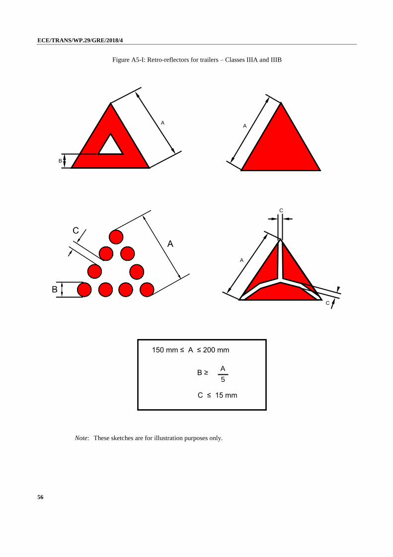
ECE/TRANS/WP.29/GRE/2018/4
56
Figure A5-I: Retro-reflectors for trailers – Classes IIIA and IIIB
Note: These sketches are for illustration purposes only.
A
B
A
C
C
A
150 mm ≤ A ≤ 200 mm
B ≥
C ≤ 15 mm
A
5
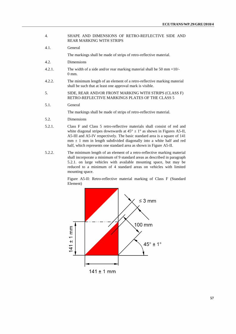
ECE/TRANS/WP.29/GRE/2018/4
57
4. SHAPE AND DIMENSIONS OF RETRO-REFLECTIVE SIDE AND
REAR MARKING WITH STRIPS
4.1. General
The markings shall be made of strips of retro-reflective material.
4.2. Dimensions
4.2.1. The width of a side and/or rear marking material shall be 50 mm +10/-
0 mm.
4.2.2. The minimum length of an element of a retro-reflective marking material
shall be such that at least one approval mark is visible.
5. SIDE, REAR AND/OR FRONT MARKING WITH STRIPS (CLASS F)
RETRO-REFLECTIVE MARKINGS PLATES OF THE CLASS 5
5.1. General
The markings shall be made of strips of retro-reflective material.
5.2. Dimensions
5.2.1. Class F and Class 5 retro-reflective materials shall consist of red and
white diagonal stripes downwards at 45° ± 1° as shown in Figures A5-II,
A5-III and A5-IV respectively. The basic standard area is a square of 141
mm ± 1 mm in length subdivided diagonally into a white half and red
half, which represents one standard area as shown in Figure A5-II.
5.2.2. The minimum length of an element of a retro-reflective marking material
shall incorporate a minimum of 9 standard areas as described in paragraph
5.2.1. on large vehicles with available mounting space, but may be
reduced to a minimum of 4 standard areas on vehicles with limited
mounting space.
Figure A5-II: Retro-reflective material marking of Class F (Standard
Element)
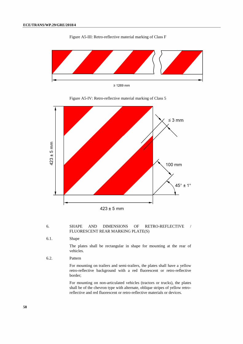
ECE/TRANS/WP.29/GRE/2018/4
58
Figure A5-III: Retro-reflective material marking of Class F
Figure A5-IV: Retro-reflective material marking of Class 5
6. SHAPE AND DIMENSIONS OF RETRO-REFLECTIVE /
FLUORESCENT REAR MARKING PLATE(S)
6.1. Shape
The plates shall be rectangular in shape for mounting at the rear of
vehicles.
6.2. Pattern
For mounting on trailers and semi-trailers, the plates shall have a yellow
retro-reflective background with a red fluorescent or retro-reflective
border;
For mounting on non-articulated vehicles (tractors or trucks), the plates
shall be of the chevron type with alternate, oblique stripes of yellow retro-
reflective and red fluorescent or retro-reflective materials or devices.
≥ 1269 mm
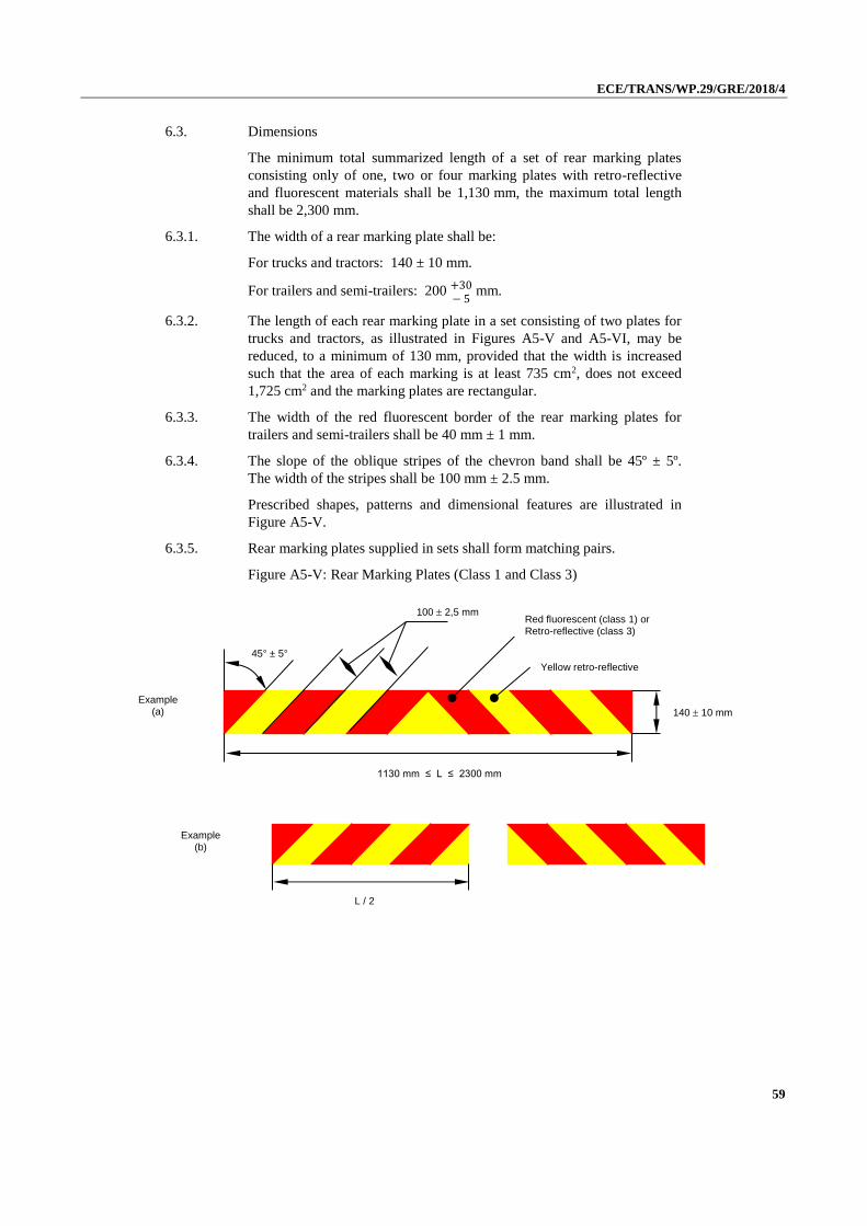
ECE/TRANS/WP.29/GRE/2018/4
59
6.3. Dimensions
The minimum total summarized length of a set of rear marking plates
consisting only of one, two or four marking plates with retro-reflective
and fluorescent materials shall be 1,130 mm, the maximum total length
shall be 2,300 mm.
6.3.1. The width of a rear marking plate shall be:
For trucks and tractors: 140 ± 10 mm.
For trailers and semi-trailers: 200 +30− 5
mm.
6.3.2. The length of each rear marking plate in a set consisting of two plates for
trucks and tractors, as illustrated in Figures A5-V and A5-VI, may be
reduced, to a minimum of 130 mm, provided that the width is increased
such that the area of each marking is at least 735 cm2, does not exceed
1,725 cm2 and the marking plates are rectangular.
6.3.3. The width of the red fluorescent border of the rear marking plates for
trailers and semi-trailers shall be 40 mm ± 1 mm.
6.3.4. The slope of the oblique stripes of the chevron band shall be 45º ± 5º.
The width of the stripes shall be 100 mm ± 2.5 mm.
Prescribed shapes, patterns and dimensional features are illustrated in
Figure A5-V.
6.3.5. Rear marking plates supplied in sets shall form matching pairs.
Figure A5-V: Rear Marking Plates (Class 1 and Class 3)
140 10 mm
Example
(a)
1130 mm ≤ L ≤ 2300 mm
100 2,5 mm Red fluorescent (class 1) or Retro-reflective (class 3)
Yellow retro-reflective
45° ± 5°
Example
(b)
L / 2
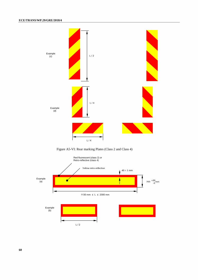
ECE/TRANS/WP.29/GRE/2018/4
60
Figure A5-VI: Rear marking Plates (Class 2 and Class 4)
Example
(c) L / 2
Example
(d)
L / 4
L / 4
Example
(a)
1130 mm ≤ L ≤ 2300 mm
200 mm +30
-5
40 1 mm
Red fluorescent (class 2) or Retro-reflective (class 4)
Yellow retro-reflective
Example
(b)
L / 2
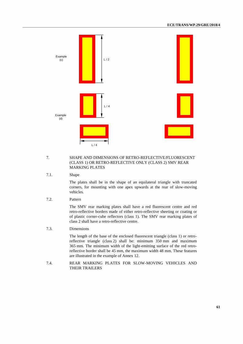
ECE/TRANS/WP.29/GRE/2018/4
61
7. SHAPE AND DIMENSIONS OF RETRO-REFLECTIVE/FLUORESCENT
(CLASS 1) OR RETRO-REFLECTIVE ONLY (CLASS 2) SMV REAR
MARKING PLATES
7.1. Shape
The plates shall be in the shape of an equilateral triangle with truncated
corners, for mounting with one apex upwards at the rear of slow-moving
vehicles.
7.2. Pattern
The SMV rear marking plates shall have a red fluorescent centre and red
retro-reflective borders made of either retro-reflective sheeting or coating or
of plastic corner-cube reflectors (class 1). The SMV rear marking plates of
class 2 shall have a retro-reflective centre.
7.3. Dimensions
The length of the base of the enclosed fluorescent triangle (class 1) or retro-
reflective triangle (class 2) shall be: minimum 350 mm and maximum
365 mm. The minimum width of the light-emitting surface of the red retro-
reflective border shall be 45 mm, the maximum width 48 mm. These features
are illustrated in the example of Annex 12.
7.4. REAR MARKING PLATES FOR SLOW-MOVING VEHICLES AND
THEIR TRAILERS
Example
(c) L / 2
Example
(d)
L / 4
L / 4
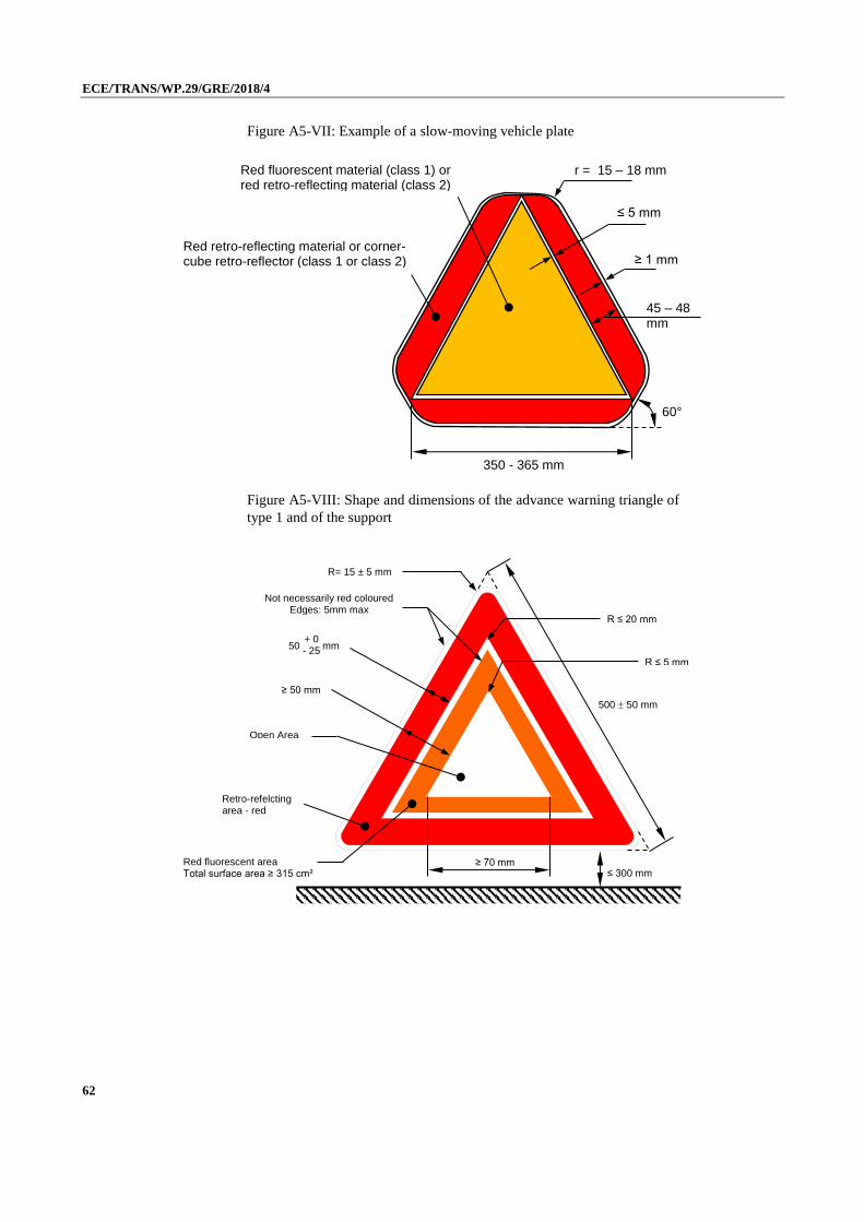
ECE/TRANS/WP.29/GRE/2018/4
62
Figure A5-VII: Example of a slow-moving vehicle plate
Figure A5-VIII: Shape and dimensions of the advance warning triangle of
type 1 and of the support
R= 15 ± 5 mm
≥ 70 mm ≤ 300 mm
Not necessarily red coloured
Edges: 5mm max
Open Area
500 50 mm
R ≤ 20 mm
R ≤ 5 mm
Red fluorescent area
Total surface area ≥ 315 cm²
Retro-refelcting
area - red
+ 0
- 25 50 mm
≥ 50 mm
60°
350 - 365 mm
≤ 5 mm
≥ 1 mm
45 – 48 mm
r = 15 – 18 mm
Red retro-reflecting material or corner-cube retro-reflector (class 1 or class 2)
Red fluorescent material (class 1) or red retro-reflecting material (class 2)
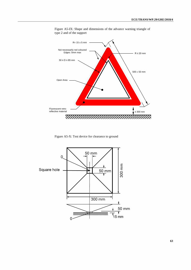
ECE/TRANS/WP.29/GRE/2018/4
63
Figure A5-IX: Shape and dimensions of the advance warning triangle of
type 2 and of the support
Figure A5-X: Test device for clearance to ground
R= 15 ± 5 mm
≤ 300 mm
Not necessarily red coloured
Edges: 5mm max
Open Area
500 50 mm
R ≤ 20 mm
Fluorescent retro
reflective material
50 ≤ D ≤ 85 mm
ECE/TRANS/WP.29/GRE/2018/4
64
Annex 6
Resistance to heat
1. Test procedure in the case of moulded plastics reflectors of retro-reflecting
devices as Classes IA, IB, IIIA, IIIB, IVA, SMV, Marking plates of classes 1,
2, 3, 4, 5, and Advance warning triangle of type 1:
The retro-reflective device shall be kept for 48 consecutive hours in a dry
atmosphere at a temperature of 65 °C ± 2 °C after which the sample shall be
allowed to cool for 1 hour at 23 °C ± 2 ºC.
2. Test procedure in the case of use of flexible materials for Classes C, F, 1, 2,
3, 4, 5 and Advance warning triangle of type 2:
A section of a sample unit not less than 300 mm long shall be kept for 12
hours in a dry atmosphere at a temperature of 65 °C ± 2 ºC, after which the
sample shall be allowed to cool for 1 hour at 23 °C ± 2 ºC. It shall then be
kept for 12 hours at a temperature of - 20 °C ± 2 ºC.
The sample shall be examined after a recovery time of 4 hours under normal
laboratory conditions.
3. After this test, no cracking or appreciable distortion of the retro-reflective
device and, in particular, of its optical component must be visible.
ECE/TRANS/WP.29/GRE/2018/4
65
Annex 7
Resistance to water penetration for retro-reflective devices and Advance warning triangles
1. TEST FOR RETRO-REFLECTIVE DEVICES
1.1. Retro-reflective devices whether part of a lamp or not, or a sample unit of
retro-reflective marking, shall be stripped of all removable parts and
immersed for 10 minutes in water at a temperature of 50 °C ± 5 °C, the
highest point of the upper part of the illuminating surface being 20 mm below
the surface of the water. This test shall be repeated after turning the retro-
reflective device through 180°, so that the illuminating surface is at the
bottom and the rear face is covered by about 20 mm of water. These sample
units shall then be immediately immersed in the same conditions in water at a
temperature of 25 °C ± 5 °C.
1.2. No water shall penetrate to the reflecting surface of the retro-reflecting
optical unit. If visual inspection clearly reveals the presence of water, the
device shall not be considered to have passed the test.
1.3. If visual inspection does not reveal the presence of water or in case of doubt:
1.3.1. In the case of retro-reflectors, the CIL shall be measured by the method
described in Annex 4 or Annex 14, the retro-reflective device being first
lightly shaken to remove excess water from the outside.
1.3.2. In the case of a sample unit of retro-reflective marking the coefficient of
retro-reflection R' shall be measured in conformity with Annex 7, the sample
unit being first lightly shaken to remove excess water from the outside.
2. TEST FOR ADVANCE WARNING TRIANGLES
2.1. Test of resistance of the retro-reflective device or fluorescent retro-reflecting
material
2.1.1. The triangle - collapsible triangles are to be assembled as for use - shall be
immersed for 10 minutes in water having a temperature of 50 °C ± 5 °C, with
the highest point of the upper part of the illuminating surface being about
20 mm below the water surface. Immediately afterwards, this retro-reflective
device shall be immersed under the same conditions in water having a
temperature of 25 °C ± 5 °C.
2.1.2. After this test, no water shall have penetrated to the reflecting surface of the
retro-reflective device. If a visual inspection clearly reveals the presence of
water, the device has not passed the test. Water or water vapour penetration
into the edges of fluorescent retro-reflecting materials shall not be deemed to
indicate failure.
2.1.3. If the visual inspection does not reveal the presence of water, or in case of
doubt the value of the CIL shall again be measured under the same conditions
as specified in paragraph 1.2. of Annex 7, after the retro-reflective device has
been gently shaken to remove excess water from the outside. The CIL shall
not have diminished by more than 40 per cent of the values recorded before
the test.
2.2. Water test
ECE/TRANS/WP.29/GRE/2018/4
66
The triangle - collapsible advance warning triangles are to be assembled as
for use - shall be immersed flat for two hours on the bottom of a tank
containing water at 25 °C ± 5 °C, with the active face of the triangle showing
upwards and being 5 cm under the surface of the water. The triangle shall
then be removed and dried. No part of the device may exhibit clear signs of
deterioration which might impair the effectiveness of the triangle.
ECE/TRANS/WP.29/GRE/2018/4
67
Annex 8
Alternative test procedures of resistance to water penetration for retro-reflective devices of the Classes IB and IIIB
1. As an alternative, at the request of the manufacturer, the following tests
(moisture and dust test) shall be applied.
2. MOISTURE TEST
The test evaluates the ability of the sample device to resist moisture
penetration from a water spray and determines the drainage capability of
those devices with drain holes or other exposed openings in the device.
2.1. Water spray test equipment
A water spray cabinet with the following characteristics shall be used:
2.1.1. Cabinet
The cabinet shall be equipped with a nozzle(s) which provides a solid cone
water spray of sufficient angle to completely cover the sample device. The
centreline of the nozzle(s) shall be directed downward at an angle of 45°± 5°
to the vertical axis of a rotating test platform.
2.1.2. Rotating test platform
The rotating test platform shall have a minimum diameter of 140 mm and
rotate about a vertical axis in the centre of the cabinet.
2.1.3. Precipitation rate
The precipitation rate of the water spray at the device shall be 2.5 (+1.6/-0)
mm/min as measured with a vertical cylindrical collector centred on the
vertical axis of the rotating test platform. The height of the collector shall be
100 mm and the inside diameter shall be a minimum of 140 mm.
2.2. Water spray test procedure
A sample device mounted on a test fixture, with initial CIL measured and
recorded shall be subjected to a water spray as follows:
2.2.1. Device openings
All drain holes and other openings shall remain open. Drain wicks, when
used, shall be tested in the device.
2.2.2. Rotational speed
The device shall be rotated about its vertical axis at a rate of 4.0 ± 0.5 min -1.
2.2.3. If the retro-reflector is reciprocally incorporated or grouped with signalling or
lighting functions, these functions shall be operated at design voltage
according to a cycle of 5 min ON (in flashing mode, where appropriate),
55 min OFF.
2.2.4. Test duration
The water spray test shall last 12 hours (12 cycles of 5/55 min).
2.2.5. Drain period
ECE/TRANS/WP.29/GRE/2018/4
68
The rotation and the water spray shall be turned OFF and the device allowed
to drain for 1 hour with the cabinet door closed.
2.2.6. Sample evaluation
Upon completion of the drain period. The interior of the device shall be
observed for moisture accumulation. No standing pool of water shall be
allowed to be formed, or which can be formed by tapping or tilting the
device. The CIL shall be measured according to the method specified in
Annex 4 after having dried the exterior of the device with a dry cotton cloth.
2.3. DUST EXPOSURE TEST
This test evaluates the ability of the sample device to resist dust penetration
which could significantly affect the photometric output of the retro-reflector.
2.3.1. Dust exposure test equipment
The following equipment shall be used to test for dust exposure:
2.3.2. Dust exposure test chamber
The interior of the test chamber shall be cubical in shape in size 0.9 to 1.5 m
per side. The bottom may be "hopper shaped" to aid in collecting the dust.
The internal chamber volume, not including a "hopper shaped" bottom shall
be 2 m3 maximum and shall be charged with 3 to 5 kg of the test dust. The
chamber shall have the capability of agitating the test dust by means of
compressed air or blower fans in such a way that the dust is diffused
throughout the chamber.
2.3.3. The dust
The test dust used shall be fine powdered cement in accordance with standard
ASTM C 150-84.*
2.3.4. Dust exposure test procedure
A sample device, mounted on a test fixture, with the initial CIL measured and
recorded, shall be exposed to dust as follows:
2.3.5. Device openings
All drain holes and other openings shall remain open. Drain wicks, when
used, shall be tested in the device.
2.3.6. Dust exposure
The mounted device shall be placed in the dust chamber no closer than
150 mm from a wall. Devices with a length exceeding 600 mm shall be
horizontally centred in the test chamber. The test dust shall be agitated as
completely as possible by compressed air or blower(s) at intervals of 15 min
for a period of 2 to 15 s for the duration of 5 hours. The dust shall be allowed
to settle between the agitation periods.
2.3.7. Measured sample evaluation
Upon completion of the dust exposure test, the exterior of the device shall be
cleaned and dried with a dry cotton cloth and the CIL measured according to
the method specified in Annex 4.
* American Society for Testing and Materials
ECE/TRANS/WP.29/GRE/2018/4
69
Annex 9
Resistance to fuels
1. A test mixture of 70 vol. per cent of n-heptane and 30 vol. per cent of toluol
shall be applied for either:
1.1. a retro-reflective device;
(a) the outer surface of the retro-reflective device and, in particular, of the
illuminating surface, shall be lightly wiped with a cotton cloth soaked
in the test mixture.
(b) after about five minutes, the surface shall be inspected visually. It
must not show any apparent surface changes, except that slight surface
cracks will not be objected to.
or;
1.2. a sample unit of retro-reflective marking;
(a) a section of a sample unit not less than 300 mm long shall be
immersed in the test mixture for one minute.
(b) after removal, the surface shall be wiped dry with a soft cloth and
shall not show any visible change which would reduce its effective
performance.
2. Test for advance warning triangles:
2.1. The triangle and its protective cover shall be immersed separately in a tank
containing a mixture of 70 per cent n-heptane and 30 per cent toluene.
(a) After 60 seconds they shall be removed from the tank and drained of
excess liquid.
(b) The triangle shall then be placed in its cover and the unit shall be laid
flat in a still atmosphere.
(c) When completely dried, the triangle shall not adhere to its protective
cover, and there shall be no visually noticeable change on its surface
and shall not present apparent detrimental modifications; however,
slight surface cracks may be tolerated.
ECE/TRANS/WP.29/GRE/2018/4
70
Annex 10
Resistance to lubricating oils
1. TEST PROCEDURE IN THE CASE OF MOULDED PLASTICS
REFLECTORS AS CLASSES IA, IB, IIIA, IIIB, IVA AND ADVANCE
WARNING TRIANGLE OF TYPE 1
1.1. The outer surface of the retro-reflective device and, in particular, the
illuminating surface, shall be lightly wiped with a cotton cloth soaked in a
detergent lubricating oil. After about 5 minutes, the surface shall be cleaned.
The CIL shall then be measured (Annex 4 or Annex 14).
ECE/TRANS/WP.29/GRE/2018/4
71
Annex 11
Resistance to corrosion (ISO Standard 3768)
1. Retro-reflective devices must be so designed that they retain the prescribed
photometric and colorimetric characteristics despite the humidity and
corrosive influences to which they are normally exposed. The resistance of
the front surface to tarnishing and of the protection of the rear face to
deterioration shall be checked, particularly when an essential metal
component seems liable to be attacked.
2. The retro-reflective device, or the lamp if the device is combined with a light,
shall be stripped of all removable parts and subjected to the action of a saline
mist for a period of 50 hours, comprising two periods of exposure of 24 hours
each, separated by an interval of two hours during which the sample is
allowed to dry.
3. The saline mist shall be produced by atomizing, at a temperature of
35 °C ± 2 °C, a saline solution obtained:
3.1. IN THE CASE OF MOULDED PLASTICS REFLECTORS AS CLASSES
IA, IB, IIIA, IIIB, IVA AND ADVANCE WARNING TRIANGLE OF
TYPE 1
by dissolving 20 ± 2 parts by weight of sodium chloride in 80 parts of
distilled water containing not more than 0.02 per cent of impurities.
3.1.1. Immediately after completion of the test, the sample must not show signs of
excessive corrosion liable to impair the efficiency of the device.
3.2. IN THE CASE OF A SAMPLE UNIT OF RETRO-REFLECTIVE
MARKING,
by dissolving 5 parts by weight of sodium chloride in 95 parts of distilled
water containing not more than 0.02 per cent of impurities.
3.2.1. Immediately after completion of the test, the sample shall show no sign of
corrosion liable to impair the efficiency of the marking.
4. The coefficient of retro-reflection R' of the retro-reflective areas, when
measured after a recovery period of 48 hours as specified in Annex 7, at an
entrance angle of ß2 = 5 and an observation angle of α = 20', shall be not less
than the value in Table 9 or more than the value in Table 10 respectively.
Before measuring, the surface shall be cleaned to remove salt deposits from
the saline mist.
ECE/TRANS/WP.29/GRE/2018/4
72
Annex 12
Resistance of the accessible rear face of mirror-backed retro-reflective devices
1. Resistance of the accessible rear face of mirror-backed retro-reflective
devices, in the case of moulded plastics reflectors as Classes IA, IB, IIIA,
IIIB, IVA and Advance warning triangle of type 1.
2. The reverse side of the retro-reflective device shall be brushed with a hard
nylon brush.
3. After having brushed in the case of moulded plastics reflectors as Classes IA,
IB, IIIA, IIIB and IVA the rear face of the retro-reflective device, a cotton
cloth soaked in the mixture, defined in Annex 9 shall be applied to the said
rear face for one minute. The cotton cloth is then removed and the retro-
reflective device left to dry.
4. After having brushed, in the case of moulded plastics reflectors of Advance
warning triangle of type 1, the reverse side of the retro-reflective device shall
then covered or thoroughly wetted for one minute with a defined in Annex 9.
The fuel shall then be removed and the device allowed to dry.
5. As soon as evaporation is completed, the reverse side shall be brushed with
the same brush as before.
6. The CIL shall then be measured (Annex 4 or Annex 14) after the whole
surface of the mirror-backed rear face has been covered with Indian ink.
7. In the case of the retro-reflector of an Advance warning triangle of type 1, the
CIL shall not have diminished by more than 40 per cent of the values
recorded before the test. This test is not applicable for fluorescent retro-
reflecting material.
ECE/TRANS/WP.29/GRE/2018/4
73
Annex 13
Resistance to weathering
1. RESISTANCE TO WEATHERING IN THE CASE OF A SAMPLE UNITS
OF RETRO-REFLECTIVE MARKING DEVICES
1.1. Procedure - For each test, two specimens of a sample unit are taken. One
specimen shall be stored in a dark and dry container for subsequent use as
"reference unexposed specimen".
1.2. The second specimen shall be subjected to a source of illumination with a
temperature and irradiation test described in Annex 22, if required in in the
relevant paragraph 5. of this UN Regulation:
(a) The retro-reflector or retro-reflective material shall be exposed until
blue standard No. 7 has faded to No. 4 on the grey scale blue standard
No. 7.
(b) The fluorescent material or fluorescent / retro-reflective material shall
be exposed until blue standard No. 5 has faded to No. 4 on the grey
scale.
1.3. After the test, the specimen shall be washed in a dilute neutral detergent
solution, dried and examined for conformity with the requirements specified
in paragraphs 1.4. and 1.5.
1.4. Visual appearance
No area of the exposed specimen shall show any evidence of cracking,
scaling, splitting, blistering, delamination, distortion, chalking, staining or
corrosion.
The sample shall not exhibit any visible damage such as cracks, scaling or
peeling of the fluorescent or of the fluorescent retro-reflecting material.
1.5. Colour fastness
The colours of the exposed specimen shall still meet the requirements
specified in the paragraph 5. of this UN Regulation. for the corresponding
retro-reflective device.
1.6. Effect on the coefficient of retro-reflection of the retro-reflective material:
1.6.1. For this check, measurements shall be made only at an observation angle of
α = 20' and an entrance angle of ß2 = 5 by the method given in Annex 7.
1.6.2. The coefficient of retro-reflection of the exposed specimen when dry shall be
not less than 80 per cent of the value in paragraph 5. of this UN Regulation.
2. RESISTANCE TO WEATHERING IN THE CASE OF ADVANCE
WARNING TRIANGLES
2.1. Test of the weather-resistance of the luminance factor and of the colour of the
fluorescent (advance warning triangle of type 1) and fluorescent retro-
reflecting (advance warning triangle of type 2) materials.
2.2. One of the samples of the fluorescent material submitted according to
paragraph 3.1. of this UN Regulation shall be subjected to a temperature and
irradiation test as described in Annex 9 until the contrast No. 4 of the grey
ECE/TRANS/WP.29/GRE/2018/4
74
scale has been reached for the reference sample No. 5 or the light exposure
equivalents for blue wool light fastness references sample No. 5 to fade to the
grey scale 4 for exposure by a Xenon-arc lamp has been reached.
2.3. For a retro-reflective device with the fluorescent material, after this test, the
colour co-ordinates and the luminance factor (see paragraph 3.) shall comply
with the specification in the paragraph 5. of this UN Regulation.
The luminance factor shall comply with paragraph 5. of this UN Regulation
and shall not have increased by more than 5 per cent compared with the value
ascertained according to paragraph 5. of this UN Regulation.
2.4. If the fluorescent material is an adhesive film which had already successfully
passed the above-mentioned tests in a previous approval test, the test need
not be repeated; a corresponding note shall be entered under item 12
("Remarks") in the communication concerning approval (Annex 1).
2.5. Test of the weather-resistance of the luminance factor and of the colour of the
fluorescent (advance warning triangle of type 1) and fluorescent retro-
reflecting (advance warning triangle of type 2) materials.
ECE/TRANS/WP.29/GRE/2018/4
75
Annex 14
Stability of photometric properties
1. The approval granting authority has the right to test the optical properties
stability of a retro-reflecting material in use (when used for marking or as
distinctive markings/graphics).
2. The Administrative Departments of Contracting Parties, in which the
approval was granted, may undertake the same tests. If "systematic failures in
use" occur for a type of retro-reflective material, the tested material samples
shall be transferred for appraisal to the authority which granted approval.
3. If other criteria are missing, the notation "systematic failures in use" for a
type of retro-reflective material is to be established according to paragraph 5.
4. The authority which granted approval shall have the right to check the
stability in time of the optical properties of a type of rear marking plate in
service.
5. The Competent Authorities of countries other than the country in which
approval was granted may carry out similar checks in their territory. If a type
of rear marking plate in use exhibits a systematic defect, the said authorities
shall transmit to the authority which granted approval, with a request for its
opinion, any components removed for examination.
6. In the absence of other criteria, the concept of "systematic defect" of a type of
rear marking plate in use shall be interpreted in conformity with the intention
of paragraph 5.
ECE/TRANS/WP.29/GRE/2018/4
76
Annex 15
Resistance to cleaning in the case of a sample unit of retro-reflective marking devices
1. MANUAL CLEANING
A test sample smeared with a mixture of detergent lubricating oil and
graphite shall be easily cleaned without damage to the retro-reflective surface
when wiped with a mild aliphatic solvent such as n-heptane, followed by
washing with a neutral detergent.
2. POWER WASHING
When subjected to a continuous spraying action for 60 seconds on the test
component in its normal mounting conditions, a test sample shall show no
damage to the retro-reflective surface or delamination from the substrate or
separation from the sample mounting surface under the following set-up
parameters:
(a) Water/wash solution pressure 8 ± 0.2MPa;
(b) Water/wash solution temperature 60° - 5 °C;
(c) Water/wash solution flow rate 7 ± 1 l/min;
(d) The tip of the cleaning wand to be positioned at distance of 600 ± 20
mm away from the retro-reflective surface;
(e) Cleaning wand to be held at no greater angle than 45 degrees from
perpendicular to the retro-reflective surface;
(f) 40-degree nozzle creating wide fan pattern.
ECE/TRANS/WP.29/GRE/2018/4
77
Annex 16
Bonding strength
1. BONDING STRENGTH (IN THE CASE OF ADHESIVE MATERIALS)
FOR RETRO-REFLECTING MARKINGS
1.1. The adhesion of retro-reflective materials shall be determined after 24 hours
curing time by utilising a 90-degree peel on a tensile strength testing
machine.
1.2. The retro-reflective materials shall not be easily removable without damaging
the material.
1.3. The retro-reflective materials shall need a force of at least 10 N per 25 mm
width at a constant speed of 300 mm per minute to be removed from their
substrate.
2. BONDING STRENGTH (IN THE CASE OF ADHESIVE MATERIALS)
FOR RETRO-REFLECTIVE MATERIAL FOR REAR MARKING
PLATES
2.1. The adhesion of retro-reflective materials shall be determined after 24 hours
curing time by utilizing a 90-degree peel on a tensile strength testing
machine.
2.2. The adhesion of laminated or coated retro-reflective and fluorescent materials
shall be determined.
2.3. The coated materials, of whatever kind, shall not be removable without tools
or without damaging the material.
2.4. The laminated materials (adhesive films) shall need a force of at least 10 N
per 25 mm width, at a speed of 300 mm per minute, to be removed from the
substrate.
ECE/TRANS/WP.29/GRE/2018/4
78
Annex 17
Flexing - Retro-reflecting Markings
1. For samples that are to be adhered to a flexible substrate, i.e. tarpaulin, the
following shall apply:
2. A specimen of the sample unit that measures 50 mm by 300 mm shall be bent
once lengthwise, around a 3.2 mm mandrel with adhesive contacting the
mandrel for a period of 1 second.
3. The test temperature shall be 23 °C 2 °C.
Note: For ease of testing, spread talcum powder on the adhesive to prevent
sticking to the mandrel.
4. After this test, the specimen shall not have cracking of the surface and shall
not show any visible change that would reduce its effective performance.
ECE/TRANS/WP.29/GRE/2018/4
79
Annex 18
Resistance to impact
1. REAR MARKING PLATES (EXCEPT FOR PLASTICS CORNER-CUBE
REFLECTORS)
When a 25 mm diameter solid steel ball is dropped from a height of 2 m onto
the retro-reflective and fluorescent surfaces of a supported plate, at an
ambient temperature of 23 ± 2ºC, the material shall show no cracking or
separation from the substrate at a distance of more than 5 mm from the
impacted area.
2. RETRO-REFLECTIVE DEVICES OF THE CLASSE IVA
The retro-reflective device shall be mounted in a manner similar to the way in
which it is mounted on the vehicle, but with the lens faced horizontal and
directed upwards.
Drop a 13 mm diameter polished solid steel ball, once, vertically onto the
central part of the lens from a height of 0.76 m. The ball may be guided but
not restricted in free fall.
When a retro-reflective device is tested at room temperature with this
method, the lens shall not crack.
ECE/TRANS/WP.29/GRE/2018/4
80
Annex 19
Rigidity of plates
1. CLASSES 1, 2, 3, 4 AND 5
1.1. The rear marking plate shall be placed on two supports in such a way that the
supports are parallel to the shorter edge of the plate and the distance from
either support to the adjacent edge of the plate shall not exceed L 10, where L
is the greater overall dimension of the plate. The plate shall then be loaded
with bags of shot or of dry sand to a uniformly distributed pressure of 1.5
kN/m2. The deflection of the plate shall be measured at a point midway
between the supports.
1.2. When tested as described in paragraph 1. above, the maximum deflection of
the plate under the test load shall not exceed one twentieth of the distance
between the supports in paragraph 1. and the residual deflection after removal
of the load shall not exceed one fifth of the measured deflection under load.
2. CLASS SMV
2.1. The triangular plate shall be strongly held on one of its long sides, with the
clamps of the holding device not encroaching over more than 20 mm. A force
of 10N perpendicular to the plane shall be applied to the opposite apex.
2.2. The apex shall then not move in the direction of the force by more than
40 mm.
2.3. After removal of the force, the plate shall visibly return to its initial position.
The residual deflection shall not be more than 5 mm.
ECE/TRANS/WP.29/GRE/2018/4
81
Annex 20
Further test procedures for Advance Warning Triangles of Type 1 and 2
1. TEST OF CLEARANCE TO GROUND
1.1. The advance warning triangle shall be required to pass the following tests:
1.1.1. For this test, the apparatus shown in Figure A5-X, which has the form of an
inverted hollow pyramid, shall be placed on a horizontal base plane.
1.1.2. The individual supports to the ground shall be placed one after another in the
square hole of the test apparatus. During the test of each support, it shall be
required to find a position of the test apparatus in relation to the advance
warning triangle and its supporting device, which is favourable for the
triangle and which ensures that:
1.1.2.1. All supports are resting simultaneously on the base plane,
1.1.2.2. Outside the area covered by the test apparatus, the distance between the base
plane and parts of the triangle as well as of the supporting device is at least
50 mm (with the exception of the supports proper).
2. MECHANICAL SOLIDITY TEST
2.1. When the advance warning triangle has been set up as required by the
manufacturer and its bases are firmly held, a force of 2 N shall be applied to
the apex of the triangle parallel to the supporting surface and normal to the
lower side of the triangle.
2.2. The apex of the triangle shall not move more than 5 cm in the direction in
which the force is exerted.
2.3. After the test, the position of the device shall not be significantly different
from its original position.
3. TEST OF HEAT AND LOW-TEMPERATURE RESISTANCE
3.1. The advance warning triangle, in its protective cover, if provided, shall be
kept for 12 consecutive hours in a dry atmosphere at a temperature of
60 °C ± 2 °C.
3.2. After the test, no cracking or noticeable distortion of the device shall be
visible; this applies in particular to the retro-reflective device. The cover shall
be readily openable and shall not adhere to the triangle.
3.3. After the heat-resistance test and subsequent storage for 12 consecutive hours
at a temperature of 25 °C ± 5 °C, the advance warning triangle, in its
protective cover, is to be kept for another 12 hours in a dry atmosphere at a
temperature of -40 °C ± 2 °C.
3.4. Immediately after removal from the cold room, no fractures or any visible
distortion shall be noticeable on the device and especially on its optical parts.
The protective cover, if provided, shall be properly openable, and it shall
neither tear nor adhere to the advance warning triangle.
4. Determination of the roughness of the road surface "sandy beach" method
4.1. Purpose of the method
ECE/TRANS/WP.29/GRE/2018/4
82
4.1.1. The purpose of this method is to describe and to determine to a certain extent
the geometric roughness of that part of the road surface on which the advance
warning triangle is placed during the test of stability in wind, as required
according to Annex 5, paragraph 10.
4.2. Principle of the method
4.2.1. A known volume V of sand is spread evenly on the surface of the
carriageway in the form of a circle. The ratio of the volume used to the area S
covered is defined as "mean sand depth" HS and is expressed in mm:
S
VHS
4.2.2. The test is carried out by means of round-grain, dry sand and having a grain
size between 0.160 mm and 0.315 mm. The volume amounts to
25 ml ± 0.15 ml. The sand is spread out over the surface where the test is
carried out by means of a flat, circular disc with a diameter of 65 mm, one
side of which is covered with a sheet of rubber having a thickness of 1.5 mm
to 2.5 mm and the other being provided with an appropriate handle. If the
diameter of the circular area covered with sand is D mm, the mean sand
depth will be calculated in accordance with the formula:
mm10D
254HS 3
2
4.3. Performance of the test
4.3.1. The surface on which the test is to be carried out shall be dry and at first be
brushed with a soft brush to remove any dirt or loose gravel.
4.3.2. The sand which has been firmly filled into an appropriate receptacle is then
poured out on the surface to be tested in a single heap. The sand is then
carefully spread out on the surface by means of repeated circular movements
of the rubber faced disc so as to form the largest possible round area covered
with sand. The sand will then fill all depressions and hollows.
4.3.3. Two diameters, at right angles to one another, of the "beach" thus formed are
usually measured. The mean value is rounded off to the nearest 5 mm, with
the depth of the sand HS being calculated according to the formula given in
paragraph 4.2.2.
4.3.4. Six tests of this kind are carried out on the supporting surface, with the parts
to be tested being distributed over the surface to be tested as evenly as
possible. The overall mean of the results obtained is given as the mean sand
depth HS of the road surface where the advance warning triangle has been
placed.
5. TEST OF STABILITY AGAINST WIND
5.1. The advance warning triangle shall be set up in a wind tunnel, on a base
measuring about 1.50 m by 1.20 m with a surface formed of abrasive material
of the type P36 corresponding to the FEPA** specification 43-1-2006. This
surface shall be characterised by its geometric roughness, HS = 0.5 mm ±
** FEPA: Federation of European Producers of Abrasives, 20 Avenue Reille, 75014 Paris, France.
ECE/TRANS/WP.29/GRE/2018/4
83
0.05 mm, which shall be defined and determined by the so-called "sandy
beach" method according to Annex 4 of this UN Regulation.
To avoid a laminar boundary layer of the incident flow over the surface of
the base, this base shall have a splitter plate and shall be set up in such a way,
that the flow is completely around the plate.
5.2. For the air flow the following conditions shall apply:
(a) The air stream shall reach a dynamic pressure of 180 Pa; and shall
have a flow field which shall be homogeneous and free of turbulence;
(b) The dimension of the flow field shall be such, that horizontally to each
corner and vertical to the top of the advance warning triangle a
clearance of at least 150 mm to the border line of this flow field shall
exist;
(c) The air stream (flow field) shall be parallel to the supporting surface,
in a direction which seems to be most unfavourable for the stability;
(d) In the case of a closed wind tunnel, the area of the advance warning
triangle shall be not larger than 5 per cent of the area cross-section of
the closed wind tunnel.
5.3. When set up in this manner, the advance warning triangle shall be subjected
for 3 minutes to this open-air stream.
5.4. The advance warning triangle shall neither overturn nor shift. Slight shifting
of the points of contact with the road surface by not more than 5 cm,
however, shall be allowed.
5.5. The retro-reflecting triangular part of the device shall not rotate through more
than 10° round a horizontal axis or a vertical axis from its initial position.
The rotation around the horizontal axis or the vertical axis shall be
determined by the aid of a virtual plane at the initial position of the retro-
reflecting triangular part of the device, which is orthogonal to the base and
orthogonal to the air stream.
ECE/TRANS/WP.29/GRE/2018/4
84
Annex 21
Colour-fastness1 of retro-reflective devices of the Classes IA, IB, IIIA, IIIB and IVA
1. The Type Approval Authority which granted approval shall have the right to
check the colour-fastness of a type of retro-reflective device in service.
2. The competent authorities of countries other than the country in which
approval was granted may carry out similar checks in their territory. If a type
of retro-reflector in use exhibits a systematic defect, the said authorities shall
transmit any components removed for examination to the Type Approval
Authority which granted approval, with a request for its opinion.
3. In the absence of other criteria, the concept "systematic defect" of a type of
retro-reflector in use shall be interpreted in conformity with the intention of
paragraph 9.1. of this UN Regulation.
1 Despite the importance of tests to check the colour-fastness of retro-reflective devices, it is in the
present state of the art not yet possible to assess colour-fastness by laboratory tests of limited
duration.
ECE/TRANS/WP.29/GRE/2018/4
85
Annex 22
Colour fastness to artificial light - Xenon-arc lamp test
1. SCOPE
This annex specifies a method intended for determining the resistance of the
colour of test samples of all kinds and in all forms to the action of an artificial
light source representative of natural daylight (D65).
2. PRINCIPLE
A specimen of the test samples to be tested is exposed to artificial light under
prescribed conditions, along with a blue wool reference as specified.
3. REFERENCE MATERIALS
The colour fastness ratings mentioned in this annex are obtained by
comparison unexposed with exposed specified blue wool references for
verification of the radiation dose as a required maximum contrast in this
UN Regulation.
3.1. Blue wool references developed and produced in Europe are identified by the
numerical designation 1 to 8. These references are blue wool cloths dyed
with the dyes listed in Table A22-1. For the test procedure of this UN
Regulation described by this annex only the blue wool references 5 and 7 will
be applied as described in Table A22-1.
Table A22-1: Dyes for blue wool references 5 and 7
Reference Dye (Colour Index designation) 1
5
7
Cl Acid Blue 47
Cl Solubilised Vat Blue 5
1 The Colour Index (third edition) is published by The Society of Dyers and Colourists, P.O.
Box 244, Perkin House, 82 Grattan Road, Bradford BD1 2JB, UK, and by The American
Association of Textile Chemists and Colorists, P.O. Box 12215, Research Triangle Park, NC
27709-2215, USA.
4. GREY SCALE
The grey scale for determining changes in colour of test samples in colour
fastness tests. A precise colorimetric specification of the scale is given in
Appendix 1 to this annex.
4.1. The use of the scale is described in paragraph 2. of Appendix 1 to this annex.
5. XENON-ARC LAMP APPARATUS
The apparatus shall be either an air-cooled or water-cooled Xenon-arc
weathering device capable of exposing samples in accordance with EN ISO
4892-2.
5.1. The exposure conditions shall comply with the requirements in the Table
A22-2.
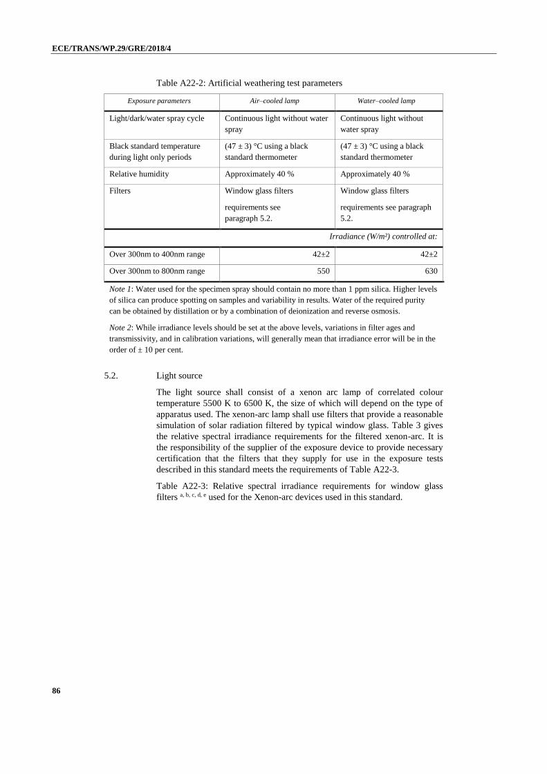
ECE/TRANS/WP.29/GRE/2018/4
86
Table A22-2: Artificial weathering test parameters
5.2. Light source
The light source shall consist of a xenon arc lamp of correlated colour
temperature 5500 K to 6500 K, the size of which will depend on the type of
apparatus used. The xenon-arc lamp shall use filters that provide a reasonable
simulation of solar radiation filtered by typical window glass. Table 3 gives
the relative spectral irradiance requirements for the filtered xenon-arc. It is
the responsibility of the supplier of the exposure device to provide necessary
certification that the filters that they supply for use in the exposure tests
described in this standard meets the requirements of Table A22-3.
Table A22-3: Relative spectral irradiance requirements for window glass
filters a, b, c, d, e used for the Xenon-arc devices used in this standard.
Exposure parameters Air–cooled lamp Water–cooled lamp
Light/dark/water spray cycle Continuous light without water
spray
Continuous light without
water spray
Black standard temperature
during light only periods
(47 ± 3) °C using a black
standard thermometer
(47 ± 3) °C using a black
standard thermometer
Relative humidity Approximately 40 % Approximately 40 %
Filters Window glass filters
requirements see
paragraph 5.2.
Window glass filters
requirements see paragraph
5.2.
Irradiance (W/m²) controlled at:
Over 300nm to 400nm range 42±2 42±2
Over 300nm to 800nm range 550 630
Note 1: Water used for the specimen spray should contain no more than 1 ppm silica. Higher levels
of silica can produce spotting on samples and variability in results. Water of the required purity
can be obtained by distillation or by a combination of deionization and reverse osmosis.
Note 2: While irradiance levels should be set at the above levels, variations in filter ages and
transmissivity, and in calibration variations, will generally mean that irradiance error will be in the
order of ± 10 per cent.
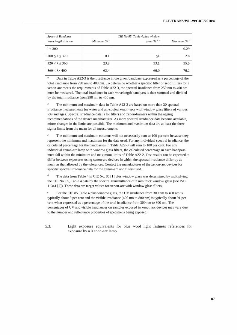
ECE/TRANS/WP.29/GRE/2018/4
87
Spectral Bandpass
Wavelength λ in nm Minimum % c
CIE No.85, Table 4 plus window
glass % d, e Maximum % c
l < 300 0.29
300 ≤ λ ≤ 320 0.1 ≤1 2.8
320 < λ ≤ 360 23.8 33.1 35.5
360 < λ ≤400 62.4 66.0 76.2
a Data in Table A22-3 is the irradiance in the given bandpass expressed as a percentage of the
total irradiance from 290 nm to 400 nm. To determine whether a specific filter or set of filters for a
xenon-arc meets the requirements of Table A22-3, the spectral irradiance from 250 nm to 400 nm
must be measured. The total irradiance in each wavelength bandpass is then summed and divided
by the total irradiance from 290 nm to 400 nm.
b The minimum and maximum data in Table A22-3 are based on more than 30 spectral
irradiance measurements for water and air-cooled xenon-arcs with window glass filters of various
lots and ages. Spectral irradiance data is for filters and xenon-burners within the ageing
recommendations of the device manufacturer. As more spectral irradiance data become available,
minor changes in the limits are possible. The minimum and maximum data are at least the three
sigma limits from the mean for all measurements.
c The minimum and maximum columns will not necessarily sum to 100 per cent because they
represent the minimum and maximum for the data used. For any individual spectral irradiance, the
calculated percentage for the bandpasses in Table A22-3 will sum to 100 per cent. For any
individual xenon-arc lamp with window glass filters, the calculated percentage in each bandpass
must fall within the minimum and maximum limits of Table A22-2. Test results can be expected to
differ between exposures using xenon-arc devices in which the spectral irradiance differ by as
much as that allowed by the tolerances. Contact the manufacturer of the xenon-arc devices for
specific spectral irradiance data for the xenon-arc and filters used.
d The data from Table 4 in CIE No. 85 [1] plus window glass was determined by multiplying
the CIE No. 85, Table 4 data by the spectral transmittance of 3 mm thick window glass (see ISO
11341 [2]). These data are target values for xenon-arc with window glass filters.
e For the CIE 85 Table 4 plus window glass, the UV irradiance from 300 nm to 400 nm is
typically about 9 per cent and the visible irradiance (400 nm to 800 nm) is typically about 91 per
cent when expressed as a percentage of the total irradiance from 300 nm to 800 nm. The
percentages of UV and visible irradiances on samples exposed in xenon arc devices may vary due
to the number and reflectance properties of specimens being exposed.
5.3. Light exposure equivalents for blue wool light fastness references for
exposure by a Xenon-arc lamp
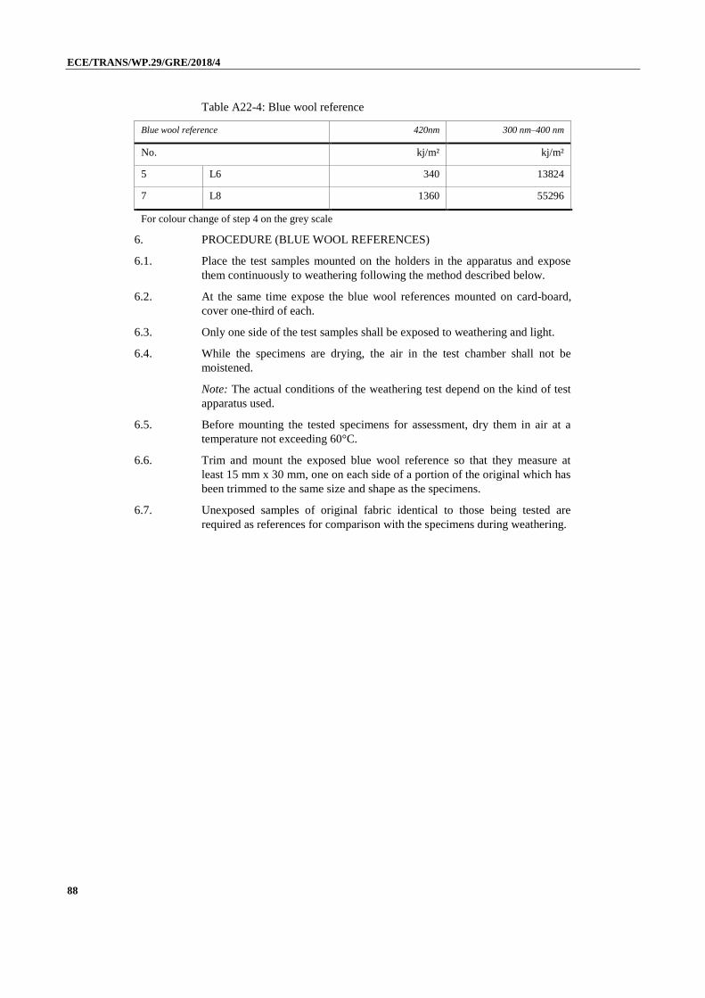
ECE/TRANS/WP.29/GRE/2018/4
88
Table A22-4: Blue wool reference
Blue wool reference 420nm 300 nm–400 nm
No. kj/m² kj/m²
5 L6 340 13824
7 L8 1360 55296
For colour change of step 4 on the grey scale
6. PROCEDURE (BLUE WOOL REFERENCES)
6.1. Place the test samples mounted on the holders in the apparatus and expose
them continuously to weathering following the method described below.
6.2. At the same time expose the blue wool references mounted on card-board,
cover one-third of each.
6.3. Only one side of the test samples shall be exposed to weathering and light.
6.4. While the specimens are drying, the air in the test chamber shall not be
moistened.
Note: The actual conditions of the weathering test depend on the kind of test
apparatus used.
6.5. Before mounting the tested specimens for assessment, dry them in air at a
temperature not exceeding 60°C.
6.6. Trim and mount the exposed blue wool reference so that they measure at
least 15 mm x 30 mm, one on each side of a portion of the original which has
been trimmed to the same size and shape as the specimens.
6.7. Unexposed samples of original fabric identical to those being tested are
required as references for comparison with the specimens during weathering.
ECE/TRANS/WP.29/GRE/2018/4
89
Annex 22 - Appendix 1
Definition of the Grey Scale
This section describes the grey scale for determining changes in colour of test samples in
colour fastness tests, and its use. A precise colorimetric specification of the scale is given as
a permanent record against which newly prepared working standards and standards that
may have changed can be compared.
1. The essential, or 5-step, scale consists of five pairs of non-glossy grey colour
chips (or swatches of grey cloth), which illustrate the perceived colour
differences corresponding to fastness ratings 5, 4, 3, 2 and 1. This essential
scale may be augmented by the provision of similar chips or swatches
illustrating the perceived colour differences corresponding to the half-step
fastness ratings 4-5, 3-4, 2-3 and 1-2, such scales being termed 9-step scales.
The first member of each pair is neutral grey in colour and the second
member of the pair illustrating fastness rating 5 is identical with the first
member. The second members of the remaining pairs are increasingly lighter
in colour so that each pair illustrates increasing contrasts or perceived colour
differences which are defined colorimetrically. The full colorimetric
specification is given below:
1.1. The chips or swatches shall be neutral grey in colour and shall be measured
with a spectrophotometer with the specular component included. The
colorimetric data shall be calculated using CIE standard colorimetric system
for Illuminant D65;
1.2. The Y tristimulus value of the first member of each pair shall be 12 ± 1;
1.3. The second member of each pair shall be such that the colour difference
between it and the adjacent first member is as follows.
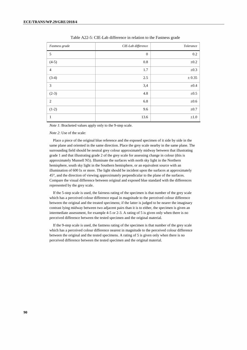
ECE/TRANS/WP.29/GRE/2018/4
90
Table A22-5: CIE-Lab difference in relation to the Fastness grade
Fastness grade CIE-Lab difference Tolerance
5 0 0.2
(4-5) 0.8 ±0.2
4 1.7 ±0.3
(3-4) 2.5 ± 0.35
3 3,4 ±0.4
(2-3) 4.8 ±0.5
2 6.8 ±0.6
(1-2) 9.6 ±0.7
1 13.6 ±1.0
Note 1: Bracketed values apply only to the 9-step scale.
Note 2: Use of the scale:
Place a piece of the original blue reference and the exposed specimen of it side by side in the
same plane and oriented in the same direction. Place the grey scale nearby in the same plane. The
surrounding field should be neutral grey colour approximately midway between that illustrating
grade 1 and that illustrating grade 2 of the grey scale for assessing change in colour (this is
approximately Munsell N5). Illuminate the surfaces with north sky light in the Northern
hemisphere, south sky light in the Southern hemisphere, or an equivalent source with an
illumination of 600 lx or more. The light should be incident upon the surfaces at approximately
45°, and the direction of viewing approximately perpendicular to the plane of the surfaces.
Compare the visual difference between original and exposed blue standard with the differences
represented by the grey scale.
If the 5-step scale is used, the fairness rating of the specimen is that number of the grey scale
which has a perceived colour difference equal in magnitude to the perceived colour difference
between the original and the treated specimens; if the latter is judged to be nearer the imaginary
contrast lying midway between two adjacent pairs than it is to either, the specimen is given an
intermediate assessment, for example 4-5 or 2-3. A rating of 5 is given only when there is no
perceived difference between the tested specimen and the original material.
If the 9-step scale is used, the fastness rating of the specimen is that number of the grey scale
which has a perceived colour difference nearest in magnitude to the perceived colour difference
between the original and the tested specimens. A rating of 5 is given only when there is no
perceived difference between the tested specimen and the original material.
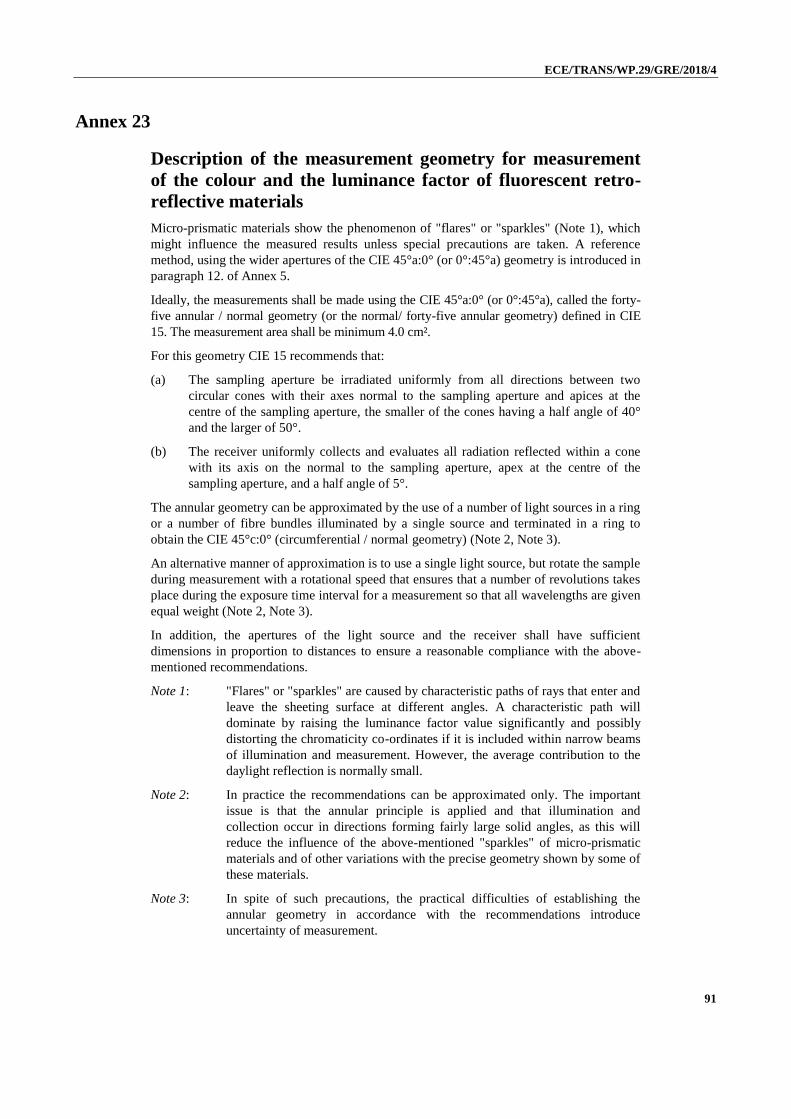
ECE/TRANS/WP.29/GRE/2018/4
91
Annex 23
Description of the measurement geometry for measurement
of the colour and the luminance factor of fluorescent retro-
reflective materials
Micro-prismatic materials show the phenomenon of "flares" or "sparkles" (Note 1), which
might influence the measured results unless special precautions are taken. A reference
method, using the wider apertures of the CIE 45°a:0° (or 0°:45°a) geometry is introduced in
paragraph 12. of Annex 5.
Ideally, the measurements shall be made using the CIE 45°a:0° (or 0°:45°a), called the forty-
five annular / normal geometry (or the normal/ forty-five annular geometry) defined in CIE
15. The measurement area shall be minimum 4.0 cm².
For this geometry CIE 15 recommends that:
(a) The sampling aperture be irradiated uniformly from all directions between two
circular cones with their axes normal to the sampling aperture and apices at the
centre of the sampling aperture, the smaller of the cones having a half angle of 40°
and the larger of 50°.
(b) The receiver uniformly collects and evaluates all radiation reflected within a cone
with its axis on the normal to the sampling aperture, apex at the centre of the
sampling aperture, and a half angle of 5°.
The annular geometry can be approximated by the use of a number of light sources in a ring
or a number of fibre bundles illuminated by a single source and terminated in a ring to
obtain the CIE 45°c:0° (circumferential / normal geometry) (Note 2, Note 3).
An alternative manner of approximation is to use a single light source, but rotate the sample
during measurement with a rotational speed that ensures that a number of revolutions takes
place during the exposure time interval for a measurement so that all wavelengths are given
equal weight (Note 2, Note 3).
In addition, the apertures of the light source and the receiver shall have sufficient
dimensions in proportion to distances to ensure a reasonable compliance with the above-
mentioned recommendations.
Note 1: "Flares" or "sparkles" are caused by characteristic paths of rays that enter and
leave the sheeting surface at different angles. A characteristic path will
dominate by raising the luminance factor value significantly and possibly
distorting the chromaticity co-ordinates if it is included within narrow beams
of illumination and measurement. However, the average contribution to the
daylight reflection is normally small.
Note 2: In practice the recommendations can be approximated only. The important
issue is that the annular principle is applied and that illumination and
collection occur in directions forming fairly large solid angles, as this will
reduce the influence of the above-mentioned "sparkles" of micro-prismatic
materials and of other variations with the precise geometry shown by some of
these materials.
Note 3: In spite of such precautions, the practical difficulties of establishing the
annular geometry in accordance with the recommendations introduce
uncertainty of measurement.
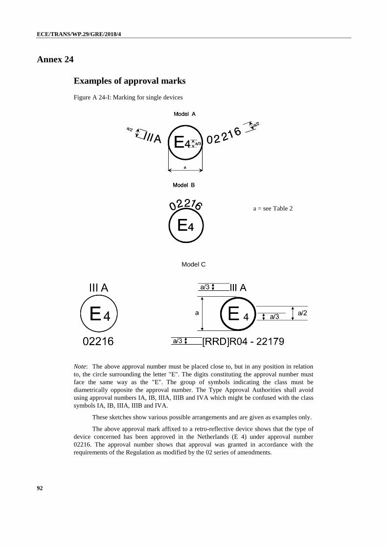
ECE/TRANS/WP.29/GRE/2018/4
92
Annex 24
Examples of approval marks
Figure A 24-I: Marking for single devices
Model C
Note: The above approval number must be placed close to, but in any position in relation
to, the circle surrounding the letter "E". The digits constituting the approval number must
face the same way as the "E". The group of symbols indicating the class must be
diametrically opposite the approval number. The Type Approval Authorities shall avoid
using approval numbers IA, IB, IIIA, IIIB and IVA which might be confused with the class
symbols IA, IB, IIIA, IIIB and IVA.
These sketches show various possible arrangements and are given as examples only.
The above approval mark affixed to a retro-reflective device shows that the type of
device concerned has been approved in the Netherlands (E 4) under approval number
02216. The approval number shows that approval was granted in accordance with the
requirements of the Regulation as modified by the 02 series of amendments.
a = see Table 2
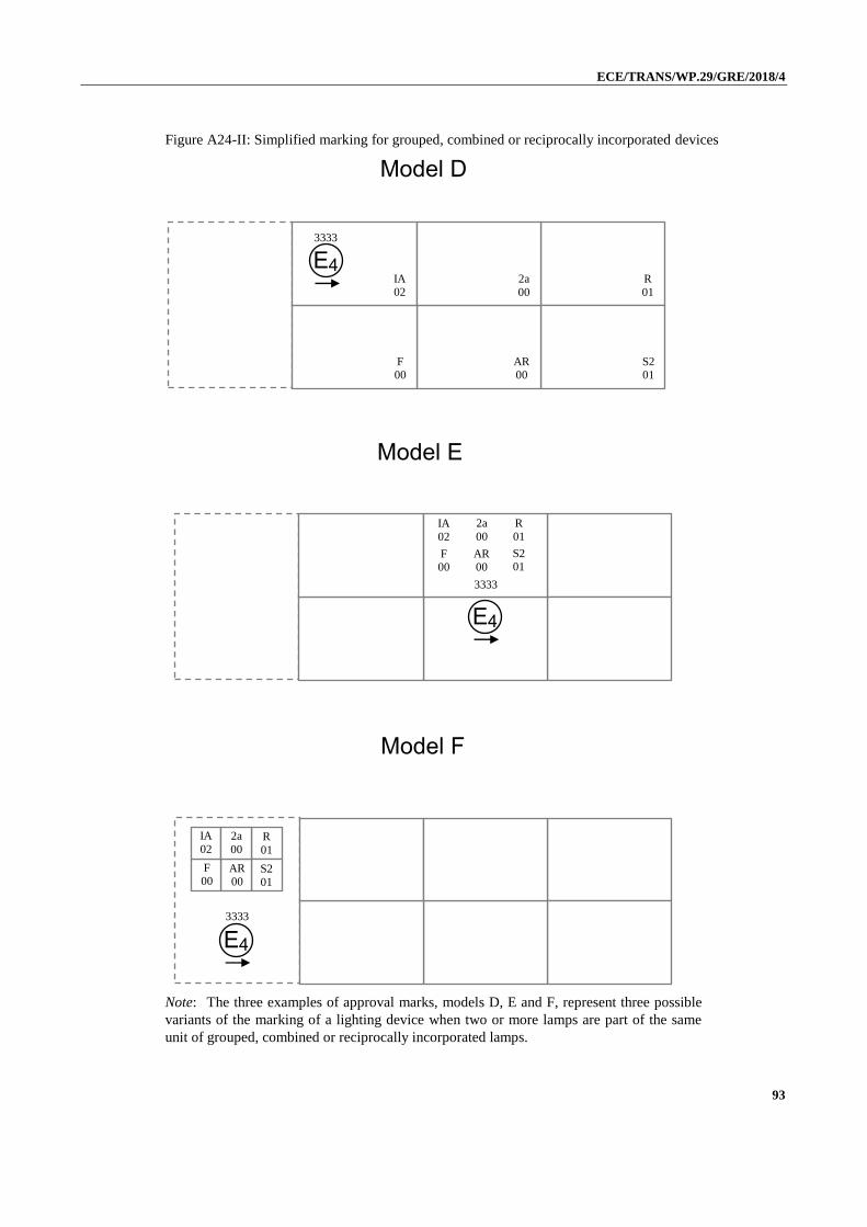
ECE/TRANS/WP.29/GRE/2018/4
93
Figure A24-II: Simplified marking for grouped, combined or reciprocally incorporated devices
Note: The three examples of approval marks, models D, E and F, represent three possible
variants of the marking of a lighting device when two or more lamps are part of the same
unit of grouped, combined or reciprocally incorporated lamps.
E 4
3333
IA 02
R 01
2a 00
F 00
S2 01
AR 00
Model D
E 4
3333
IA 02
R 01
2a 00
F 00
S2 01
AR 00
Model E
E 4
3333
IA 02
R 01
2a 00
F 00
S2 01
AR 00
Model F
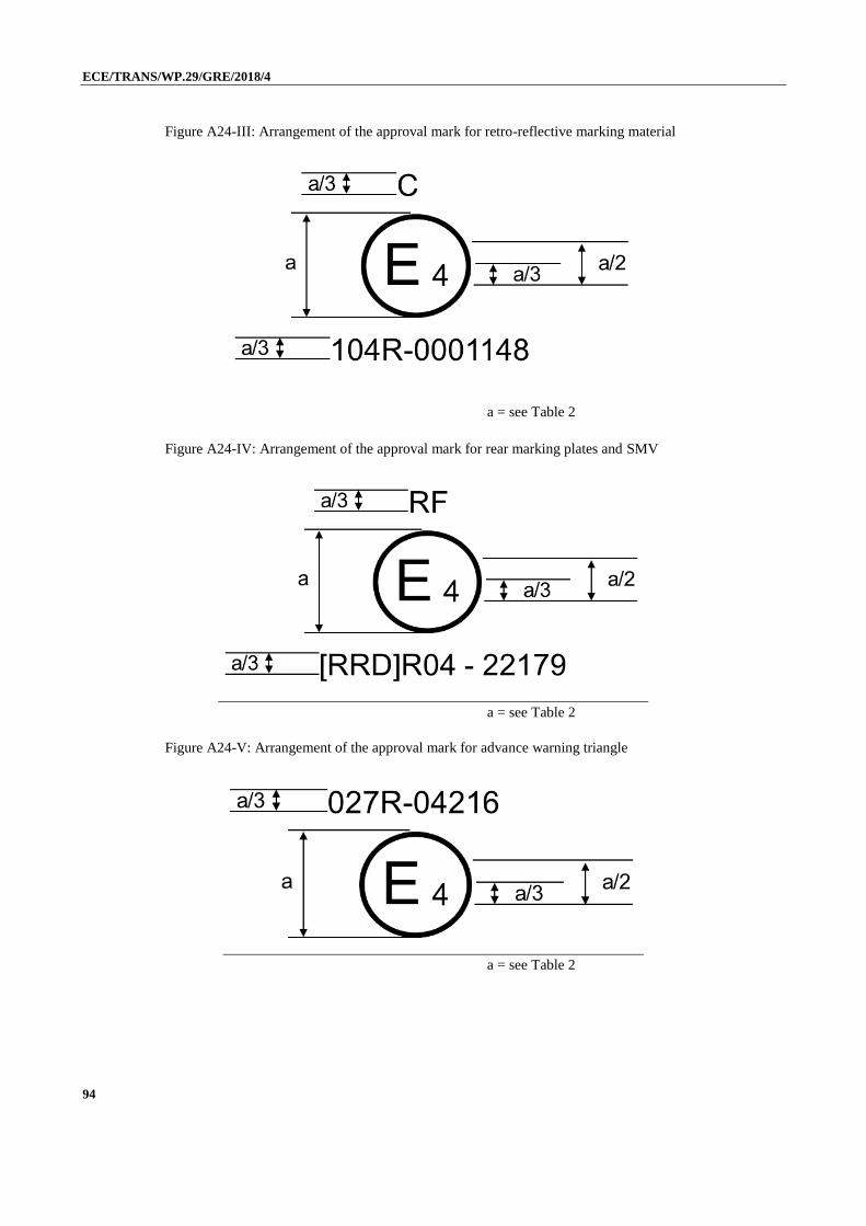
ECE/TRANS/WP.29/GRE/2018/4
94
Figure A24-III: Arrangement of the approval mark for retro-reflective marking material
a = see Table 2
Figure A24-IV: Arrangement of the approval mark for rear marking plates and SMV
a = see Table 2
Figure A24-V: Arrangement of the approval mark for advance warning triangle
a = see Table 2
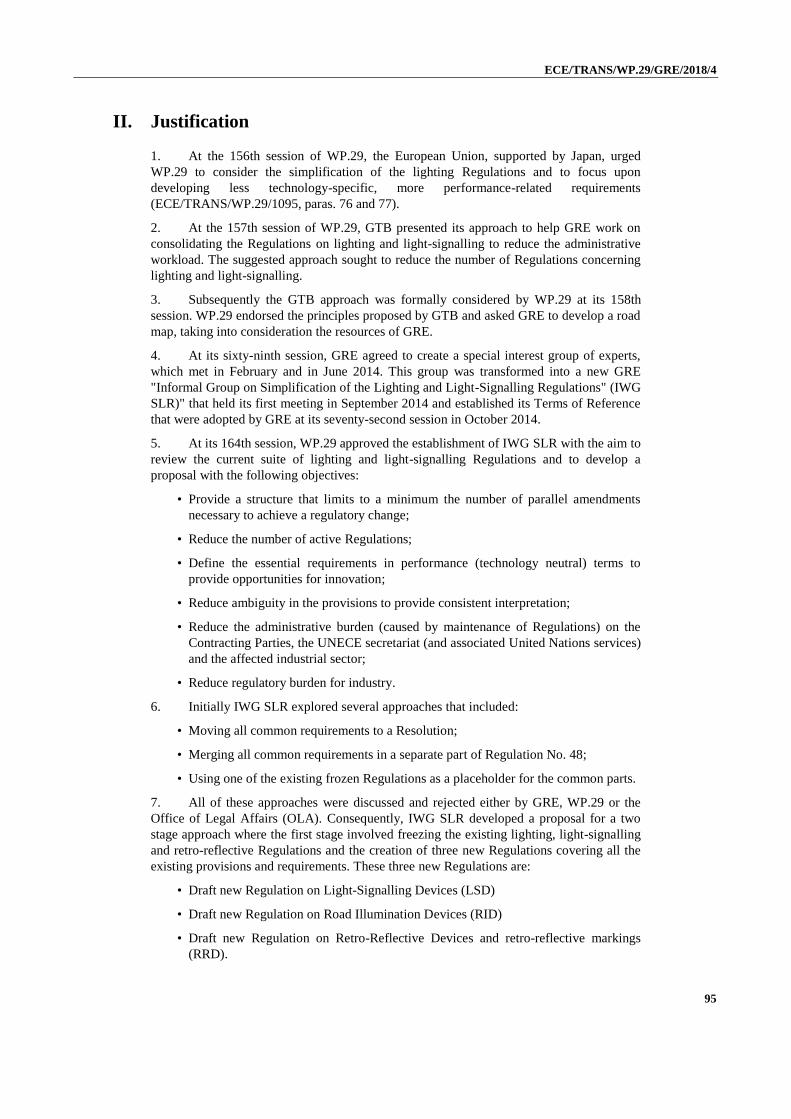
ECE/TRANS/WP.29/GRE/2018/4
95
II. Justification
1. At the 156th session of WP.29, the European Union, supported by Japan, urged
WP.29 to consider the simplification of the lighting Regulations and to focus upon
developing less technology-specific, more performance-related requirements
(ECE/TRANS/WP.29/1095, paras. 76 and 77).
2. At the 157th session of WP.29, GTB presented its approach to help GRE work on
consolidating the Regulations on lighting and light-signalling to reduce the administrative
workload. The suggested approach sought to reduce the number of Regulations concerning
lighting and light-signalling.
3. Subsequently the GTB approach was formally considered by WP.29 at its 158th
session. WP.29 endorsed the principles proposed by GTB and asked GRE to develop a road
map, taking into consideration the resources of GRE.
4. At its sixty-ninth session, GRE agreed to create a special interest group of experts,
which met in February and in June 2014. This group was transformed into a new GRE
"Informal Group on Simplification of the Lighting and Light-Signalling Regulations" (IWG
SLR)" that held its first meeting in September 2014 and established its Terms of Reference
that were adopted by GRE at its seventy-second session in October 2014.
5. At its 164th session, WP.29 approved the establishment of IWG SLR with the aim to
review the current suite of lighting and light-signalling Regulations and to develop a
proposal with the following objectives:
• Provide a structure that limits to a minimum the number of parallel amendments
necessary to achieve a regulatory change;
• Reduce the number of active Regulations;
• Define the essential requirements in performance (technology neutral) terms to
provide opportunities for innovation;
• Reduce ambiguity in the provisions to provide consistent interpretation;
• Reduce the administrative burden (caused by maintenance of Regulations) on the
Contracting Parties, the UNECE secretariat (and associated United Nations services)
and the affected industrial sector;
• Reduce regulatory burden for industry.
6. Initially IWG SLR explored several approaches that included:
• Moving all common requirements to a Resolution;
• Merging all common requirements in a separate part of Regulation No. 48;
• Using one of the existing frozen Regulations as a placeholder for the common parts.
7. All of these approaches were discussed and rejected either by GRE, WP.29 or the
Office of Legal Affairs (OLA). Consequently, IWG SLR developed a proposal for a two
stage approach where the first stage involved freezing the existing lighting, light-signalling
and retro-reflective Regulations and the creation of three new Regulations covering all the
existing provisions and requirements. These three new Regulations are:
• Draft new Regulation on Light-Signalling Devices (LSD)
• Draft new Regulation on Road Illumination Devices (RID)
• Draft new Regulation on Retro-Reflective Devices and retro-reflective markings
(RRD).
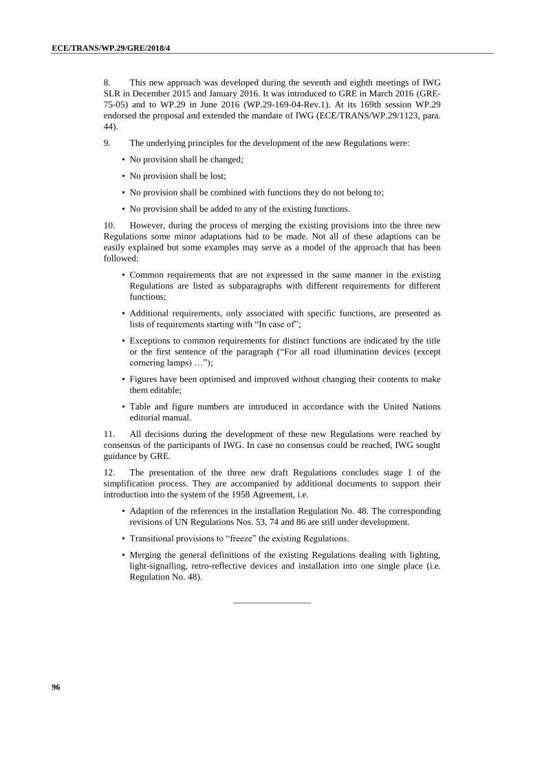
ECE/TRANS/WP.29/GRE/2018/4
96
8. This new approach was developed during the seventh and eighth meetings of IWG
SLR in December 2015 and January 2016. It was introduced to GRE in March 2016 (GRE-
75-05) and to WP.29 in June 2016 (WP.29-169-04-Rev.1). At its 169th session WP.29
endorsed the proposal and extended the mandate of IWG (ECE/TRANS/WP.29/1123, para.
44).
9. The underlying principles for the development of the new Regulations were:
• No provision shall be changed;
• No provision shall be lost;
• No provision shall be combined with functions they do not belong to;
• No provision shall be added to any of the existing functions.
10. However, during the process of merging the existing provisions into the three new
Regulations some minor adaptations had to be made. Not all of these adaptions can be
easily explained but some examples may serve as a model of the approach that has been
followed:
• Common requirements that are not expressed in the same manner in the existing
Regulations are listed as subparagraphs with different requirements for different
functions;
• Additional requirements, only associated with specific functions, are presented as
lists of requirements starting with “In case of”;
• Exceptions to common requirements for distinct functions are indicated by the title
or the first sentence of the paragraph (“For all road illumination devices (except
cornering lamps) …”);
• Figures have been optimised and improved without changing their contents to make
them editable;
• Table and figure numbers are introduced in accordance with the United Nations
editorial manual.
11. All decisions during the development of these new Regulations were reached by
consensus of the participants of IWG. In case no consensus could be reached, IWG sought
guidance by GRE.
12. The presentation of the three new draft Regulations concludes stage 1 of the
simplification process. They are accompanied by additional documents to support their
introduction into the system of the 1958 Agreement, i.e.
• Adaption of the references in the installation Regulation No. 48. The corresponding
revisions of UN Regulations Nos. 53, 74 and 86 are still under development.
• Transitional provisions to “freeze” the existing Regulations.
• Merging the general definitions of the existing Regulations dealing with lighting,
light-signalling, retro-reflective devices and installation into one single place (i.e.
Regulation No. 48).


![ECE/TRANS/WP.29/GRE/82 · Web view11.At the proposal to IWG SLR, GRE adopted further corrections to UN Regulation No. [148] (GRE-82-27, GRE-82-28, GRE-82-29 and Annex II) and requested](https://img.pdfslide.us/doc/110x75/61362fa40ad5d2067647dbdc/ecetranswp29gre82-web-view-11at-the-proposal-to-iwg-slr-gre-adopted-further.jpg)