Embed Size (px)
Citation preview

1
Electrical and Computer Engineering Dalhousie University
ECED3204: Microprocessor
Part I--Introduction
Jason J. GuDepartment of Electrical and Computer Engineering
Dalhousie University
1
Electrical and Computer Engineering Dalhousie University
Outline
i. Computer
ii. Processor
iii. Embedded System
iv. Memory
v. Program Execution
VI. AVR
VII. AVR Memory
VIII. AVR CPU Register
IX. AVR Instruction
X. AVR Addressing Mode
2

2
Electrical and Computer Engineering Dalhousie University
I: Introduction of the Computer
Computer terminology: hardware, software, Boolean algebra, bit, byte, word, double word
Computer components: processor, input devices, output devices, and memory
Categories: mainframe computers, minicomputers, microcomputers, and supercomputers
3
Electrical and Computer Engineering Dalhousie University
bit, byte, word, double word
4

3
Electrical and Computer Engineering Dalhousie University
Proposed by John von Neumann in 1945
von Neumann architecture
5
Electrical and Computer Engineering Dalhousie University
Computer Categories
Mainframe computers Original means huge size, now means very
fast, high reliable, extensive I/O, Backward Compatible
Minicomputers Smaller than Mainframe, appeared in 1960s
Microcomputers Uses a microprocessor as its CPU
Supercomputers Super fast, using multiple processor
6

4
Electrical and Computer Engineering Dalhousie University
Computer Hardware Organization
Components interconnected by buses Processor: computational operations
Input devices: means of entering programs and data
Output devices: provide access to end results
Memory devices: provide the processor ready access to programs and data
7
Electrical and Computer Engineering Dalhousie University
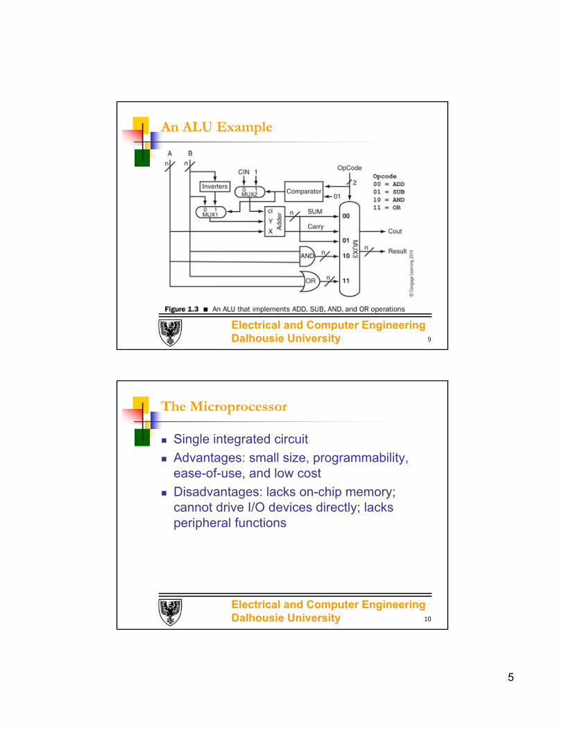
II: The Processor
The arithmetic logic unit (ALU) performs arithmetic and logic operations
Registers high-speed memory circuits
The control unit reads and interprets program instructions
The language issue Computer executes machine instructions only
Low-level vs. high-level languages
8
5
Electrical and Computer Engineering Dalhousie University
An ALU Example
9
Electrical and Computer Engineering Dalhousie University
The Microprocessor
Single integrated circuit
Advantages: small size, programmability, ease-of-use, and low cost
Disadvantages: lacks on-chip memory; cannot drive I/O devices directly; lacks peripheral functions
10
6
Electrical and Computer Engineering Dalhousie University
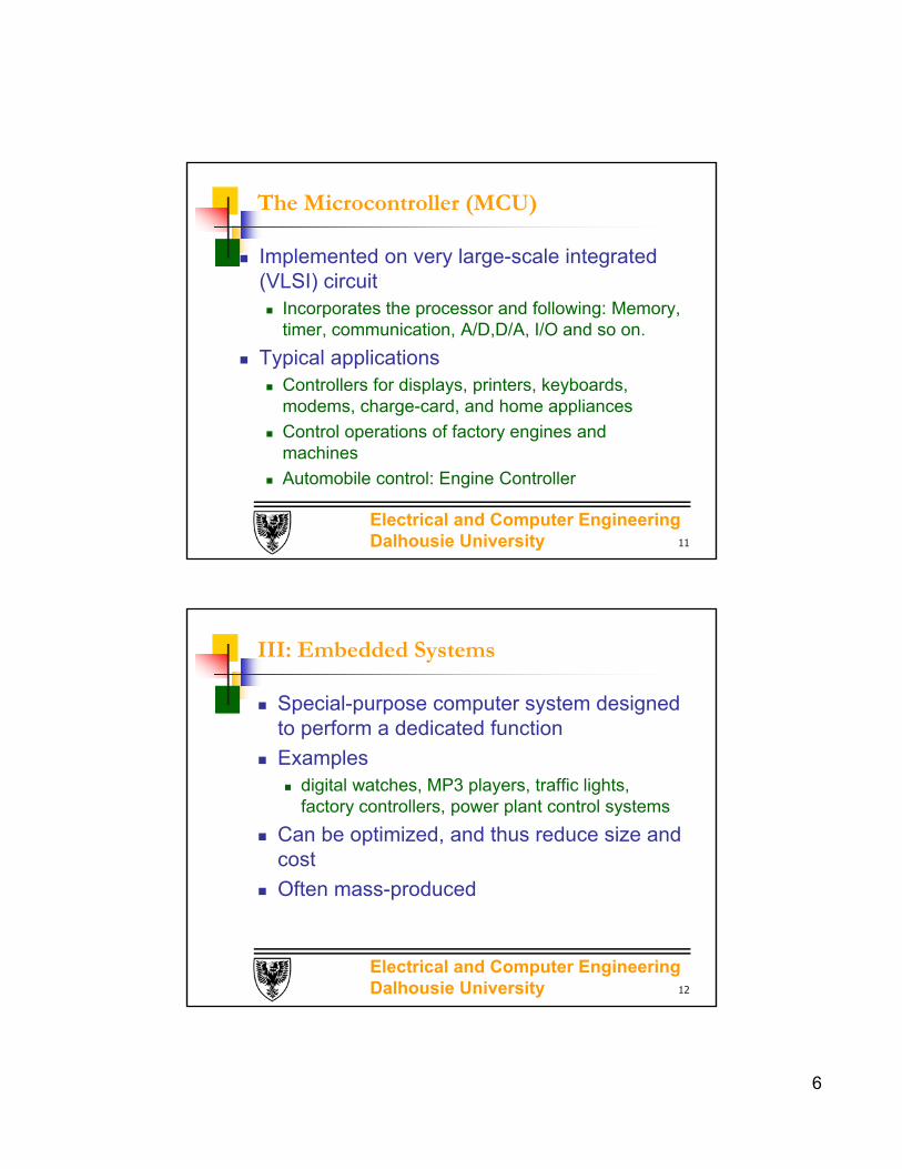
The Microcontroller (MCU)
Implemented on very large-scale integrated (VLSI) circuit Incorporates the processor and following: Memory,
timer, communication, A/D,D/A, I/O and so on.
Typical applications Controllers for displays, printers, keyboards,
modems, charge-card, and home appliances
Control operations of factory engines and machines
Automobile control: Engine Controller
11
Electrical and Computer Engineering Dalhousie University
III: Embedded Systems
Special-purpose computer system designed to perform a dedicated function
Examples digital watches, MP3 players, traffic lights,
factory controllers, power plant control systems
Can be optimized, and thus reduce size and cost
Often mass-produced
12
7
Electrical and Computer Engineering Dalhousie University
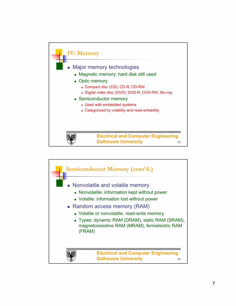
IV: Memory
Major memory technologies Magnetic memory: hard disk still used
Optic memory Compact disc (CD): CD-R, CD-RW
Digital video disc (DVD): DVD-R, DVD-RW, Blu-ray
Semiconductor memory Used with embedded systems
Categorized by volatility and read-writability
13
Electrical and Computer Engineering Dalhousie University
Semiconductor Memory (cont’d.)
Nonvolatile and volatile memory Nonvolatile: information kept without power
Volatile: information lost without power
Random access memory (RAM) Volatile or nonvolatile, read-write memory
Types: dynamic RAM (DRAM), static RAM (SRAM), magnetoresistive RAM (MRAM), ferroelectric RAM (FRAM)
14

8
Electrical and Computer Engineering Dalhousie University
Read-only memory Nonvolatile
Only allows data to be read (some exceptions)
Types: mask-programmed read-only memory (MROM), programmable read-only memory (PROM), erasable programmable read-only memory (EPROM), electrically erasable programmable read-only memory (EEPROM), flash memory
Semiconductor Memory (cont’d.)
15
Electrical and Computer Engineering Dalhousie University
Memory-System Operation
Consists of one or multiple memory chips
m x n organization m: number of memory locations
n: number of bits in each location
Each memory location: contents and address
Memory access types: read and write
16
9
Electrical and Computer Engineering Dalhousie University
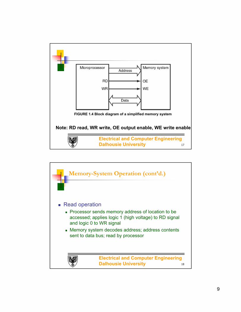
FIGURE 1.4 Block diagram of a simplified memory system
Note: RD read, WR write, OE output enable, WE write enable
17
Electrical and Computer Engineering Dalhousie University
Memory-System Operation (cont’d.)
Read operation Processor sends memory address of location to be
accessed; applies logic 1 (high voltage) to RD signal and logic 0 to WR signal
Memory system decodes address; address contents sent to data bus; read by processor
18

10
Electrical and Computer Engineering Dalhousie University
Memory-System Operation (cont’d.)
Write operation Processor: data placed on data bus, address placed
on address bus; logic 1 applied to WR signal, logic 0 to RD signal
Memory system: address decoded; value on data bus written to location
19
Electrical and Computer Engineering Dalhousie University
V: Program Execution
Mainframe computers, minicomputers, personal computers Power on: basic input/output system (BIOS) in
nonvolatile memory performs system initialization
After initialization: processor loads other programs from secondary storage
Other computers: All programs in nonvolatile memory
20
11
Electrical and Computer Engineering Dalhousie University
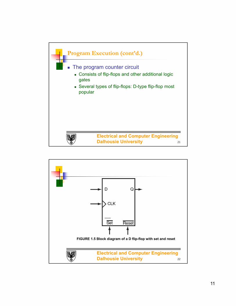
Program Execution (cont’d.)
The program counter circuit Consists of flip-flops and other additional logic
gates
Several types of flip-flops: D-type flip-flop most popular
21
Electrical and Computer Engineering Dalhousie University
FIGURE 1.5 Block diagram of a D flip-flop with set and reset
22

12
Electrical and Computer Engineering Dalhousie University
FIGURE 1.6 A simplified block diagram of the programcounter (PC) of an 8-bit microcontroller
23
Electrical and Computer Engineering Dalhousie University
Program Execution (cont’d.)
Starting program execution One approach: force PC to a fixed value when
power is turned on
Another approach: fetch program starting address from a fixed (known) memory location when power is turned on
Reset: identical to turning power on
24

13
Electrical and Computer Engineering Dalhousie University
Program Execution (cont’d.)
Instruction execution process1. Read next instruction indicated by PC
2. Decode the fetched instruction
3. Increment the PC
4. Read data the instruction requires from memory (or input device)
5. Provide the necessary data to ALU or register
25
Electrical and Computer Engineering Dalhousie University
Instruction Execution Process (cont’d.)
6. If instruction requires ALU or specialized hardware to complete, processor instructs hardware to perform requested operation
7. Write result from ALU back to a memory location or to a register or perhaps an output device
8. Jump back to step 1
26

14
Electrical and Computer Engineering Dalhousie University
VI: Introduction to AVR Microcontroller
AVR architecture provides Program and data stored in separate physical memory
address space
Ability to read data items from program memory using special instructions
Four subgroups: tinyAVR, 1-8kB Mem, 54-120 Instructions, 6-32pin, 20MHz
Mega AVR,4-256kB, 130-135 Instructions, 28-100pin, 20MHz
Xmega, 32-384kB, 142 Instruction,44-100pin, 32MHz
Application-specific AVR
27
Electrical and Computer Engineering Dalhousie University
VII: The AVR Memory Space
Figure 2.1 MEGA AVR program flashmemory map
Figure 2.2 XMEGA384A1 program memory map
28
Figure 2.1 MEGA AVR program flashmemory map
Program memory: m*16 matrix

15
Electrical and Computer Engineering Dalhousie University
The AVR Memory Space (cont’d.)
Figure 2.3 MEGA2560 data memory map, 64KB
Figure 2.4 XMEGA384A1 data memory map, 16MB
29
Electrical and Computer Engineering Dalhousie University
VIII: The AVR CPU Register
30
32-bit general purpose register with single clock cycle access time

16
Electrical and Computer Engineering Dalhousie University
The AVR CPU Register
Thirty-two 8-bit general-purpose registers with single clock cycle access time
X, Y, and Z registers: 16-bit address pointers for addressing data memory
Z register can be used to access program memory
31
Electrical and Computer Engineering Dalhousie University
The AVR CPU Register
RAMPX, RAMPY, and RAMPZ registers: concatenated with X, Y, and Z pointers to access data memory above 64 kB
RAMPZ and Z pointer for program memory
32

17
Electrical and Computer Engineering Dalhousie University
The AVR CPU Register (cont’d.)
The extended indirect register (EIND): supports extended indirect subroutine call and indirect jump in devices with program memory larger than 128 kB
33
The RAMPD register: supports direct addressing of the whole data memory space above 64 kB (XMega)
Electrical and Computer Engineering Dalhousie University
The AVR CPU Register (cont’d.)
The status register (SREG): contains information about the result of the most recently executed arithmetic or logic instruction
34

18
Electrical and Computer Engineering Dalhousie University
Figure 2.9 The SREG register
I: Global interrupt enable flag, chapter 9
T: Bit copy storage
H: Half carry flag
S: Sign bit
V: Two’s complement overflow flag
N: Negative flag
Z: Zero flag
C: Carry flag
35
Electrical and Computer Engineering Dalhousie University
IX: The AVR Instruction Set
Instruction parts: opcode and operand fields
142 instructions with 16-bit and 32-bit instructions
Instruction categories: arithmetic, control flow, data transfer, bit field manipulation, logical, and miscellaneous When an instruction has two operands, the first
operand is used as a source and destination
sub r10,r11
Summary in Appendix A of text
36

19
Electrical and Computer Engineering Dalhousie University
X: AVR Addressing Modes
1. Register direct mode: five bits used to specify register to be worked on
Example: sub r0,r1 ;r0←[r0]-[r1]
or r2,r3 ;r2←[r2]|[r3]
inc r4 ;r4←[r4]+1
Note: [ ] to refer to the content of a register or a mem location
mem(addr) refer to a data memory location
pmem(addr) refer to a program memory location
37
Electrical and Computer Engineering Dalhousie University
AVR Addressing Modes
2. I/O direct mode: six bits used to specify one of the first 64 I/O registers as an operand of an instruction
Example: in rd, A ; rd←I/O[A]
Out A,r1 ;I/O[A]←[r1]
Note: I/O registers in the extended I/O memory space
must be accessed using load(LD,LDD/LDS) and (ST/STS/STD) instructions
38

20
Electrical and Computer Engineering Dalhousie University
AVR Addressing Modes
3. Direct data mode: 16-bit value used to specify the operand address
Example: lds r1,0x1010 ;r1←[0x1010]
sts 0x1011,r2 ;mem(0x1011) ←[r2]
39
Electrical and Computer Engineering Dalhousie University
AVR Addressing Modes (cont’d.)
4. Data indirect with displacement mode: data memory address formed by adding 6-bit field from the instruction and the Y or Z pointer
example: ldd r0,Z+10 ; r0←[[Z]+10]
std Z+20,r1 ;mem([Z]+20)←[r1]
40

21
Electrical and Computer Engineering Dalhousie University
AVR Addressing Modes (cont’d.)
5. Data indirect mode: contents of one of the pointers (X, Y, or Z) used to specify the address of the data memory location to access
example: ld r0,Z ; r0←[[Z]]
st Z,r1 ;mem([Z])←[r1]
41
Electrical and Computer Engineering Dalhousie University
AVR Addressing Modes (cont’d.)
6. Data indirect with pre-decrement: contents of the pointer X, Y, or Z are decremented by 1 and then used as an address to access data memory
example: ld r0,-Z ; Z←[Z]-1;r0←[[Z]]
st -Z,r1 ; Z←[Z]-1;mem([Z])←[r1]
42
22
Electrical and Computer Engineering Dalhousie University
AVR Addressing Modes (cont’d.)
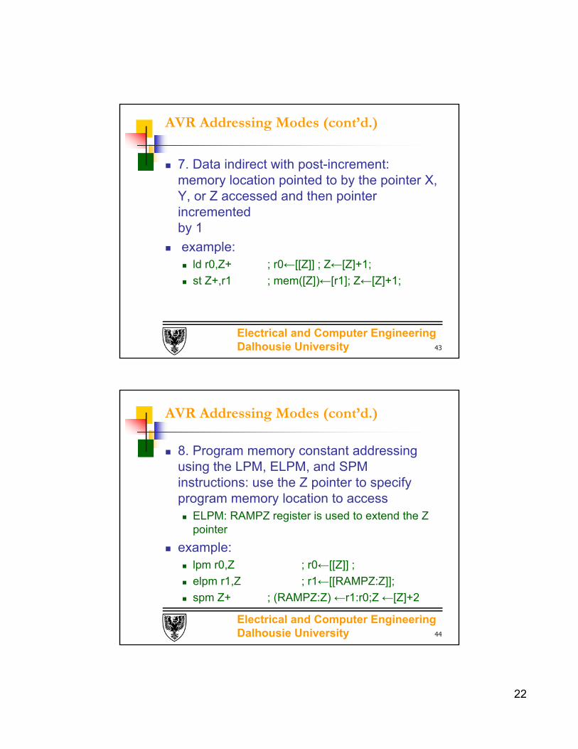
7. Data indirect with post-increment: memory location pointed to by the pointer X, Y, or Z accessed and then pointer incremented by 1
example: ld r0,Z+ ; r0←[[Z]] ; Z←[Z]+1;
st Z+,r1 ; mem([Z])←[r1]; Z←[Z]+1;
43
Electrical and Computer Engineering Dalhousie University
AVR Addressing Modes (cont’d.)
8. Program memory constant addressing using the LPM, ELPM, and SPM instructions: use the Z pointer to specify program memory location to access ELPM: RAMPZ register is used to extend the Z
pointer
example: lpm r0,Z ; r0←[[Z]] ;
elpm r1,Z ; r1←[[RAMPZ:Z]];
spm Z+ ; (RAMPZ:Z) ←r1:r0;Z ←[Z]+2
44
23
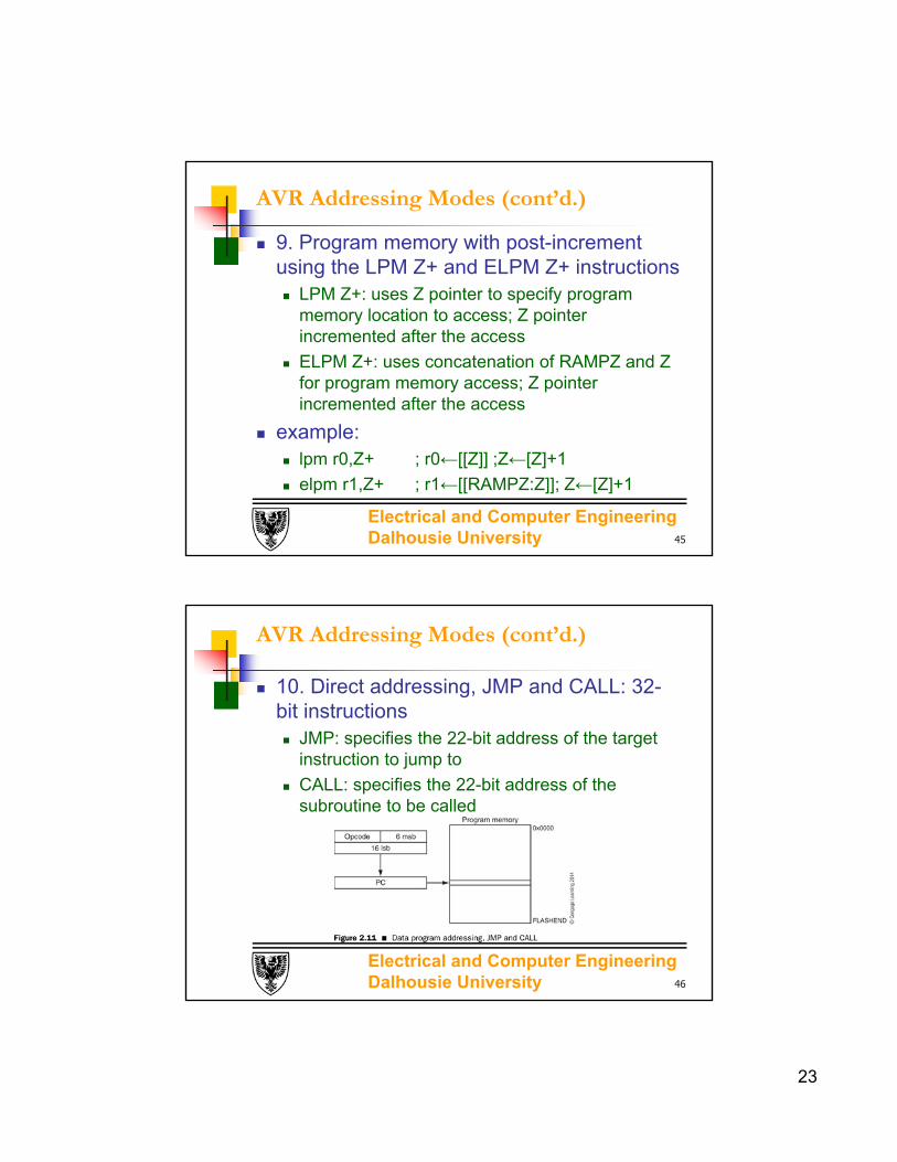
Electrical and Computer Engineering Dalhousie University
AVR Addressing Modes (cont’d.)
9. Program memory with post-increment using the LPM Z+ and ELPM Z+ instructions LPM Z+: uses Z pointer to specify program
memory location to access; Z pointer incremented after the access
ELPM Z+: uses concatenation of RAMPZ and Z for program memory access; Z pointer incremented after the access
example: lpm r0,Z+ ; r0←[[Z]] ;Z←[Z]+1
elpm r1,Z+ ; r1←[[RAMPZ:Z]]; Z←[Z]+1
45
Electrical and Computer Engineering Dalhousie University
AVR Addressing Modes (cont’d.)
10. Direct addressing, JMP and CALL: 32-bit instructions JMP: specifies the 22-bit address of the target
instruction to jump to
CALL: specifies the 22-bit address of the subroutine to be called
46

24
Electrical and Computer Engineering Dalhousie University
AVR Addressing Modes (cont’d.)
11. Indirect program addressing, IJMP and ICALL IJMP: Z pointer to specify address of the target
instruction to jump to
ICALL: Z pointer to specify address of the subroutine to be called
47
Electrical and Computer Engineering Dalhousie University
AVR Addressing Modes (cont’d.)
12. Relative program addressing, RJMP and RCALL 12-bit value used to specify distance (from the
instruction after RJMP) of the target instruction to jump to
RCALL: 12-bit value used to specify distance (from the instruction after RCALL) of the subroutine to call
48

25
Electrical and Computer Engineering Dalhousie University
A Sample of AVR Instructions
Data movement, addition, and subtraction instructions examined
AVR arithmetic and logic instructions require operand values copied from memory location to register before operation performed
49
Electrical and Computer Engineering Dalhousie University
A Sample of AVR Instructions
Data transfer instructions supported by the AVR Register to register: mov r0,r1
Constant loaded in a register: ldi rd,k
Data memory location to a register: lds r0, 0x100
Examples: Ldi r20,16 ; r20 ← 16
Ldd r20,z+5 ; r20 ←[[z]+5]
Lds r20,0x0100 ; r20 ←[0x0100]
50
26
Electrical and Computer Engineering Dalhousie University
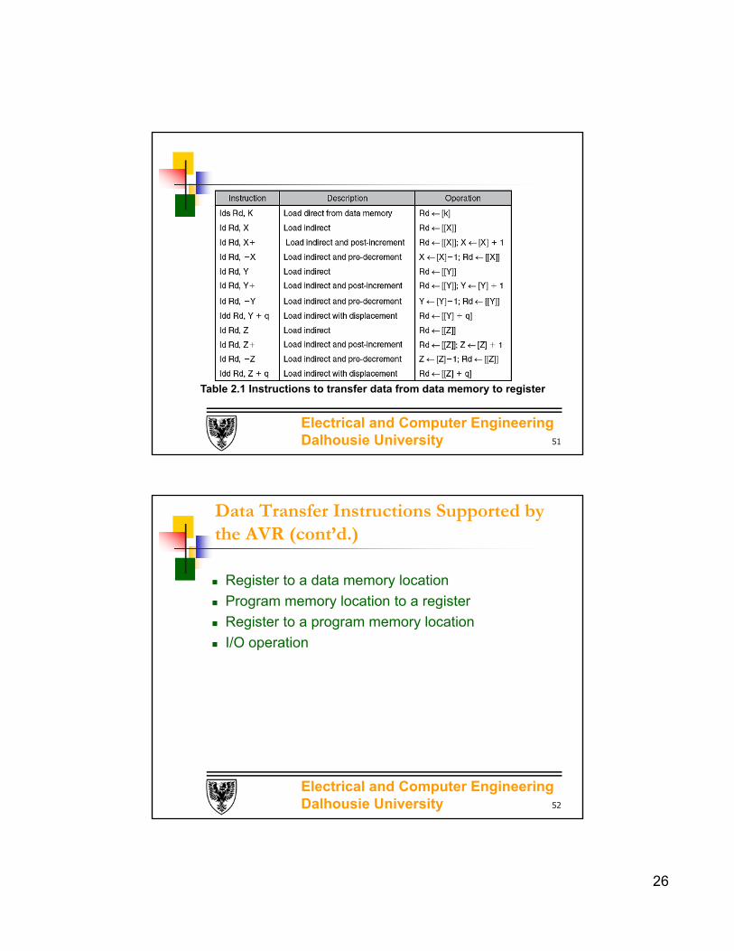
Table 2.1 Instructions to transfer data from data memory to register
51
Electrical and Computer Engineering Dalhousie University
Data Transfer Instructions Supported by the AVR (cont’d.)
Register to a data memory location
Program memory location to a register
Register to a program memory location
I/O operation
52

27
Electrical and Computer Engineering Dalhousie University
Table 2.2 Instructions to store the contents of a register in data memory
53
Electrical and Computer Engineering Dalhousie University
Table 2.3 Instructions to transfer data between a register and the program memory
54

28
Electrical and Computer Engineering Dalhousie University
A Sample of AVR Instructions (cont’d.)
Addition instruction
Table 2.4 AVR addition instructions
55
Note:Adiw rd,k; this instruction adds the constant k (0-63) to the register pair rd+1:rd and place the results in the register pair rd+1:rd , rd can only be 24,26,28,30
Electrical and Computer Engineering Dalhousie University
A Sample of AVR Instructions (cont’d.)
Subtract instructions
Table 2.5 AVR subtract instructions
56
Note:sbiw rd,k; this instruction subtract the constant k (0-63) from the register pair rd+1:rd and place the results in the register pair rd+1:rd , rd can only be 24,26,28,30