Embed Size (px)
Citation preview
ECE695 HW4 Solution Outline
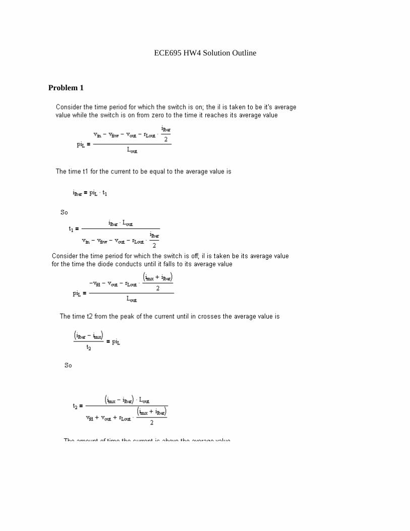
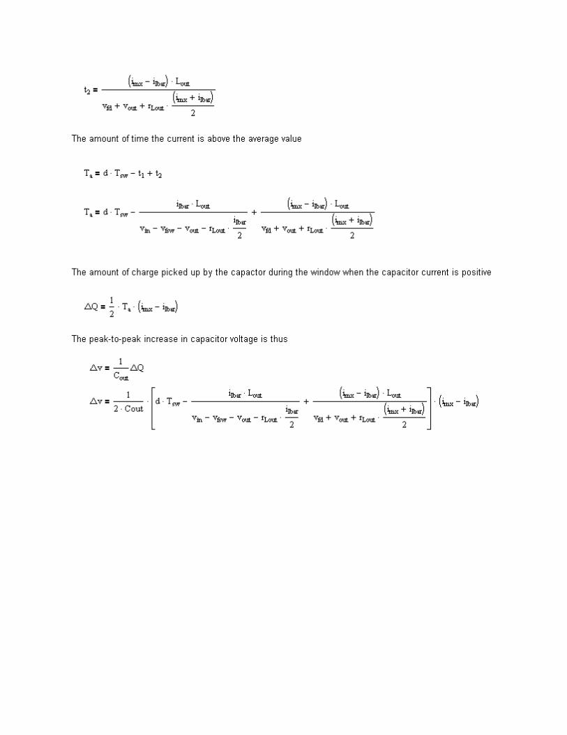
Problem 1
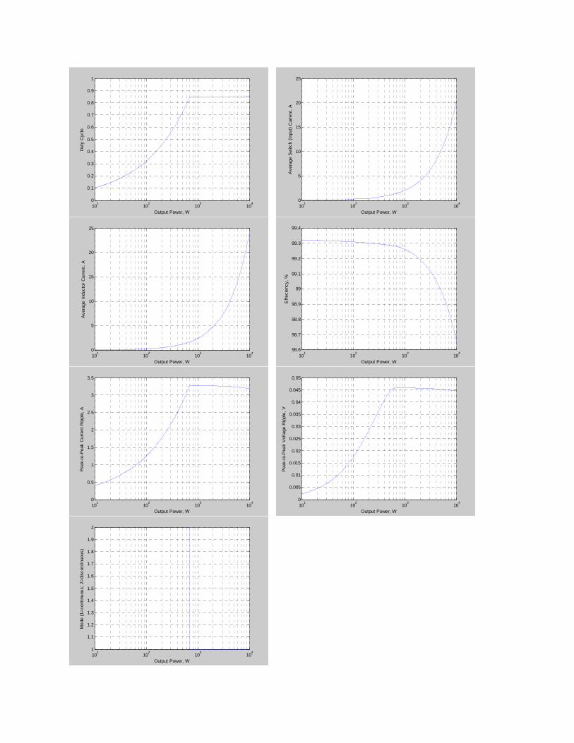
Problem 2
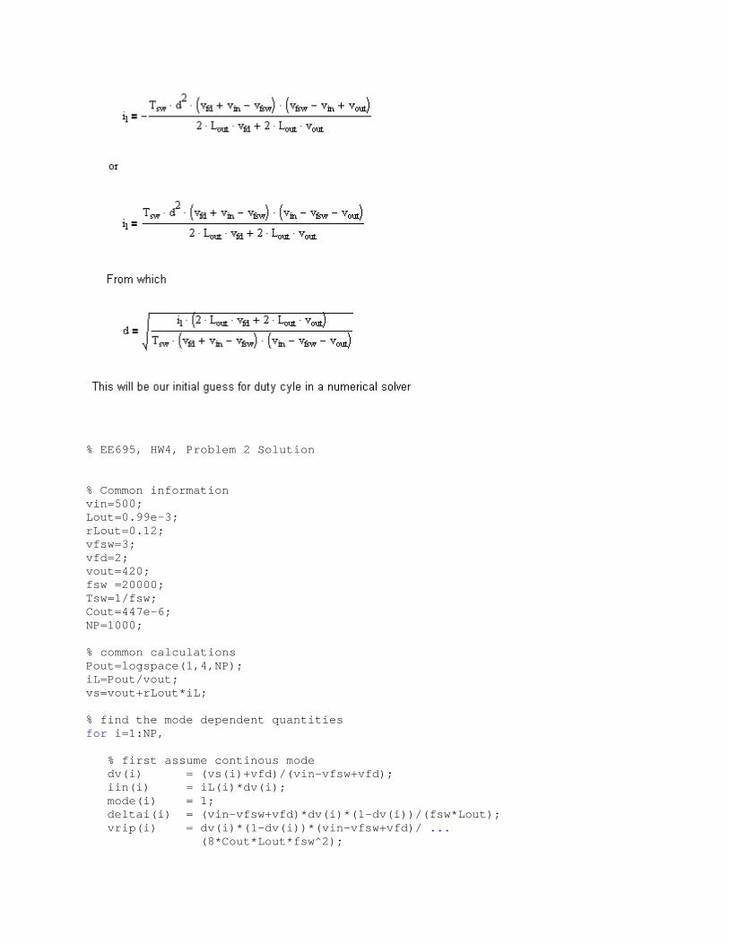
% EE695, HW4, Problem 2 Solution % Common information vin=500; Lout=0.99e-3; rLout=0.12; vfsw=3; vfd=2; vout=420; fsw =20000; Tsw=1/fsw; Cout=447e-6; NP=1000; % common calculations Pout=logspace(1,4,NP); iL=Pout/vout; vs=vout+rLout*iL; % find the mode dependent quantities for i=1:NP, % first assume continous mode dv(i) = (vs(i)+vfd)/(vin-vfsw+vfd); iin(i) = iL(i)*dv(i); mode(i) = 1; deltai(i) = (vin-vfsw+vfd)*dv(i)*(1-dv(i))/(fsw *Lout); vrip(i) = dv(i)*(1-dv(i))*(vin-vfsw+vfd)/ ... (8*Cout*Lout*fsw^2);
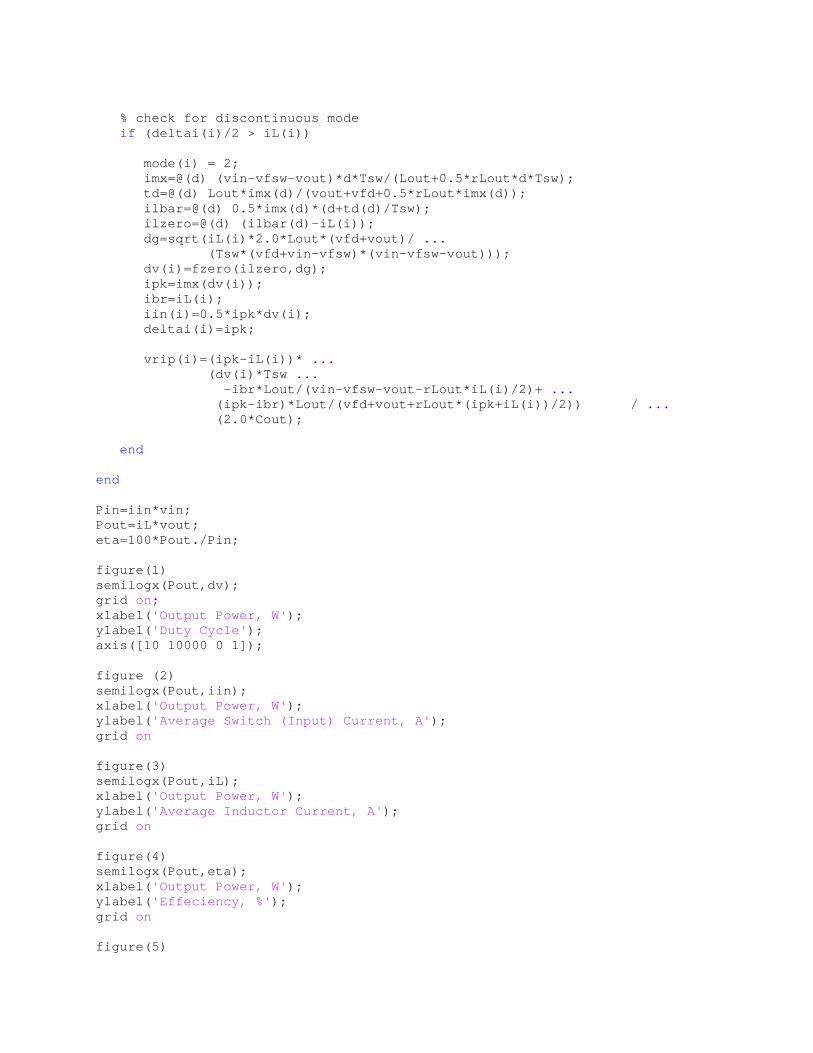
% check for discontinuous mode if (deltai(i)/2 > iL(i)) mode(i) = 2; imx=@(d) (vin-vfsw-vout)*d*Tsw/(Lout+0.5*rLou t*d*Tsw); td=@(d) Lout*imx(d)/(vout+vfd+0.5*rLout*imx(d )); ilbar=@(d) 0.5*imx(d)*(d+td(d)/Tsw); ilzero=@(d) (ilbar(d)-iL(i)); dg=sqrt(iL(i)*2.0*Lout*(vfd+vout)/ ... (Tsw*(vfd+vin-vfsw)*(vin-vfsw-vout))) ; dv(i)=fzero(ilzero,dg); ipk=imx(dv(i)); ibr=iL(i); iin(i)=0.5*ipk*dv(i); deltai(i)=ipk; vrip(i)=(ipk-iL(i))* ... (dv(i)*Tsw ... -ibr*Lout/(vin-vfsw-vout-rLout*iL(i )/2)+ ... (ipk-ibr)*Lout/(vfd+vout+rLout*(ipk+ iL(i))/2)) / ... (2.0*Cout); end end Pin=iin*vin; Pout=iL*vout; eta=100*Pout./Pin; figure(1) semilogx(Pout,dv); grid on; xlabel( 'Output Power, W' ); ylabel( 'Duty Cycle' ); axis([10 10000 0 1]); figure (2) semilogx(Pout,iin); xlabel( 'Output Power, W' ); ylabel( 'Average Switch (Input) Current, A' ); grid on figure(3) semilogx(Pout,iL); xlabel( 'Output Power, W' ); ylabel( 'Average Inductor Current, A' ); grid on figure(4) semilogx(Pout,eta); xlabel( 'Output Power, W' ); ylabel( 'Effeciency, %' ); grid on figure(5)
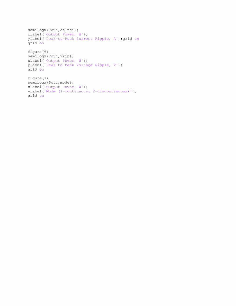
semilogx(Pout,deltai); xlabel( 'Output Power, W' ); ylabel( 'Peak-to-Peak Current Ripple, A' );grid on grid on figure(6) semilogx(Pout,vrip); xlabel( 'Output Power, W' ); ylabel( 'Peak-to-Peak Voltage Ripple, V' ); grid on figure(7) semilogx(Pout,mode); xlabel( 'Output Power, W' ); ylabel( 'Mode (1=continuous; 2=discontinuous)' ); grid on
101
102
103
104
0
0.1
0.2
0.3
0.4
0.5
0.6
0.7
0.8
0.9
1
Output Power, W
Dut
y C
ycle
101
102
103
104
0
5
10
15
20
25
Output Power, W
Ave
rage
Sw
itch
(Inp
ut)
Cur
rent
, A
101
102
103
104
0
5
10
15
20
25
Output Power, W
Ave
rage
Ind
ucto
r C
urre
nt,
A
101
102
103
104
98.6
98.7
98.8
98.9
99
99.1
99.2
99.3
99.4
Output Power, W
Eff
ecie
ncy,
%
101
102
103
104
0
0.5
1
1.5
2
2.5
3
3.5
Output Power, W
Pea
k-to
-Pea
k C
urre
nt R
ippl
e, A
101
102
103
104
0
0.005
0.01
0.015
0.02
0.025
0.03
0.035
0.04
0.045
0.05
Output Power, W
Pea
k-to
-Pea
k V
olta
ge R
ippl
e, V
101
102
103
104
1
1.1
1.2
1.3
1.4
1.5
1.6
1.7
1.8
1.9
2
Output Power, W
Mod
e (1
=co
ntin
uous
; 2=
disc
ontin
uous
)

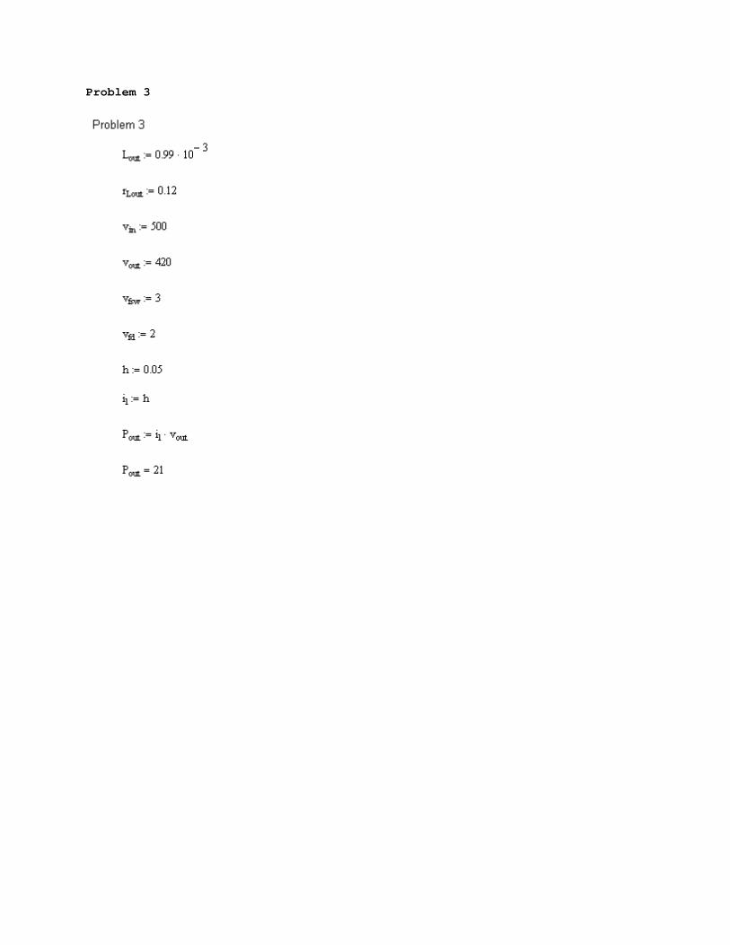
Problem 3
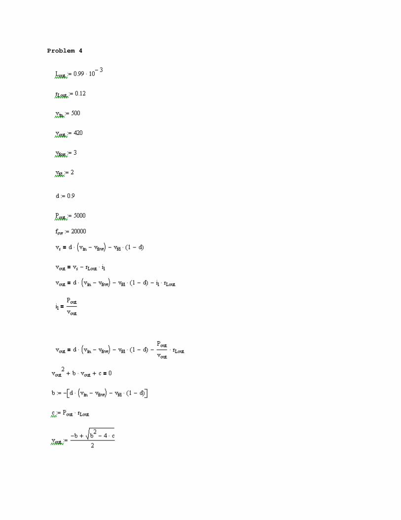
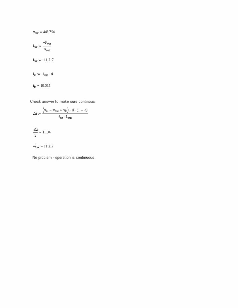
Problem 4
Problem 5
dmod.mac
"-------------------------------------------------- -------------------" " " " Author: S.D. Sudhoff " " School of Electrical Engineering " " 1285 Electrical Engineering Building " " Purdue University " " West Lafayette, IN 47905-1285 " " (765) 494-3246 " " For: ECE695,Project 2, Problem 5 " " Date: 9/25/08 " " Version: 1.0 " " " "-------------------------------------------------- -------------------" "-------------------------------------------------- -------------------" " " " MACRO: DMOD " " DESCRIPTION: Duty cycle modulator for dc/dc conve rter " " " " CONCATENATION " " " " z - identifier " " " " " " INPUTS " " " " d - duty cycle (upper switch on o ver total period) " " " " OUTPUTS " " " " s - switch signal (.true.=on,.fal se.=off) " " " " PARAMETERS " " " " fsw&z - switching frequency (Hz) " " " " INTERNAL " " " " tri&z - modulator triangle wave " " ptri&z - time derivative of triangle w ave (/s) " " slope&z - absolute value of rate of cha nge of triange " " wave (/s) " " " "-------------------------------------------------- -------------------" MACRO DDCDC(z,d,s,par_fsw) INITIAL LOGICAL s CONSTANT par_fsw "intitialize the triangle wave"
tri&z=0.0 slope&z=2.0*fsw&z ptri&z=slope&z END "compute the triangle wave and schedule changes of sign" tri&z=INTEG(ptri&z,0.0) SCHEDULE triangle&z/down&z .XP. tri&z-1.0 SCHEDULE triangle&z/up&z .XN. tri&z "schedule crossings of the triangle wave and the duty" "cycle for more accurate representation of the s witching" SCHEDULE .XZ. d-tri&z "compute the switch status" s= d .GE. tri&z DISCRETE triangle&z "This block is executed whenever triangle&z i s called" "Use if statement to sort out up and down cas es" IF (down&z) THEN ptri&z=-slope&z END IF IF (up&z) THEN ptri&z=slope&z END IF END ! triangle&z MACRO END
buckthev.mac
"-------------------------------------------------- -------------------" " " " Author: S.D. Sudhoff " " Purdue University " " School of Electrical and Computer En gineering " " 1285 Electrical Engineering Bulding " " West Lafayette, IN 47906 " " Phone: 765-494-3246 " " Fax: 765-494-0676 " " E-mail: [email protected] " " Version: 1.0 " " " "-------------------------------------------------- -------------------" "-------------------------------------------------- -------------------" " " " MACRO: Buck_THV "
" DESCRIPTION: Detailed simulation of a buck conver ter with a Thevenin" " equivalent output. " " " " CONCATENATION " " " " z - concatenation variable " " " " " " INPUTS " " " " s - switch status. .t.=switch on; .f.=switch off " " SEE modconfig&z TO CONFIGURE uin AND uout " " uin - input port input variable (in put port voltage " " or current into input port) " " uout ouput port input variable (ou tput port voltage " " or current into output port) " " " " OUTPUTS " " " " vin - input port voltage (V) " " iin - current into input port (A) " " vout - output port voltage (V) " " iout - current into output port (A) " " vc - voltage across input electrol ytic cap (with ESR)" " (V) " " il - current in output inductor (A ) " " vin_thv - input port instantaneous Thev inen equivalent " " circuit voltage (V) " " rin_thv - input port instantaneous Thev inen equivalent " " circuit resistance (Ohms) " " vout_thv - output port instantaneous The vinen equivalent " " circuit voltage (V) " " rout_thv - output port instantaneous The vinen equivalent " " circuit resistance (Ohms) " " ilout - output inductor current (A) " " " " PARAMETERS " " " " modconfig&z- model configuration (see inpu ts and outputs) " " 1: uin=vin; uout=vout; " " 2: uin=vin; uout=iout; " " 3: uin=iin; uout=iout; " " 4: uin=iin; uout=vout; " " where vin is input port volta ge, vout is output " " port voltage, iin is current into input port, " " iout is current INTO output p ort " " vsw&z - switch nominal forward voltag e drop (V) " " rsw&z - switch forward resistance (Oh ms) " " vd&z - diode nominal forward voltage drop (V) " " rd&z - diode forward resistance (Ohm s) " " Cin&z - input capacitor capacitance ( F) " " rcin&z - effective resistance of input capacitor (Ohms) " " Lout&z - output inductor inductance (H ) " " rlout&z - ouptut inductor resistance (O hms) " " Cout&z - output capacacitor capacitanc e (F) " " rcout&z - output capacitor eff. series resistance (Ohms)" " vsw&z - switch nominal forward voltag e drop (V) "
" rsw&z - switch forward resistance (Oh ms) " " vd&z - diode nominal forward voltage drop (V) " " rd&z - diode forward resistance (Ohm s) " " " " INTERNAL " " " " is&z - switch current (A) " " id&z - diode current (A) " " pvcin - time derivative of input capa citor voltage (V) " " pilout - time derivative of output ind uctor current (A) " " is&z - switch current (A) " " id&z - diode current (A) " " vc&z - input capacitor voltage (with ESR) (V) " " icin - current into input capacitor (A) " " vout&z - voltage at the output port (V ) " " icout - current into output capacitor (A) " " " "-------------------------------------------------- -------------------" MACRO Buck_THV(z,s,uin,uout,vin,iin,vout,iout,ilout , & vin_thv,rin_thv,vout_thv,rout_thv, & par_modconfig, & par_vsw,par_rsw,par_vd,par_rd, & par_cin,par_rcin,par_lout,par_rlout, & par_cout,par_rcout) INITIAL CONSTANT par_modconfig LOGICAL modconfig&z CONSTANT par_vsw CONSTANT par_vd CONSTANT par_rsw CONSTANT par_rd CONSTANT par_Cin CONSTANT par_rcin CONSTANT par_Lout CONSTANT par_rlout CONSTANT par_Cout CONSTANT par_rcout END MACRO REDEFINE piin,pvcin,pilout,pvcout,vcout,ic in,icout "compute the switch and diode current" PROCEDURAL(is&z,id&z=ilout,s) IF (ilout .GE. 0.0) THEN IF (s) THEN is&z=ilout id&z=0.0 ELSE is&z=0.0 id&z=ilout END IF ELSE id&z=0.0
is&z=0.0 END IF END "compute the total voltage across and current in to the input electrolytic" "capacitor as well as assign the input port outp ut variable" PROCEDURAL(vin,iin,icin=uin,is&z,vcin) IF ((modconfig&z .EQ. 1).OR.(modconfig&z .EQ. 2)) THEN vin=uin icin=(vin-vcin)/rcin&z iin=icin+is&z ELSE iin=uin icin=iin-is&z vin=rcin&z*icin+vcin END IF END "compute the input capacitor voltage - assume el ectrolytic" PROCEDURAL(pvcin=icin,vcin) IF ((vcin .GE. 0.0) .OR. (icin .GE. 0.0)) THE N pvcin=icin/cin&z ELSE pvcin=0.0 END IF END vcin=INTEG(pvcin,0.0) SCHEDULE .XN. vcin "compute the instantaneous thevenin equivalent c ircuit for the input" vin_thv=vcin-rcin&z*is&z rin_thv=rcin&z "compute the output voltage, output capacitor cu rrent, and output quantity" PROCEDURAL(vout,iout,icout=uout,ilout,vcout) IF ((modconfig&z .EQ. 1).OR.(modconfig&z .EQ. 4)) THEN vout=uout icout=(vout-vcout)/rcout&z iout=icout-ilout ELSE iout=uout icout=ilout+iout vout=vcout+rcout&z*icout END IF END "compute the thevenin equivalent output quantiti es" vout_thv = vcout + rcout&z*ilout rout_thv = rcout&z "compute the output capacitor voltage - assume e lectrolytic" PROCEDURAL(pvcout=vcout,icout) IF ((vcout .GT. 0.0) .OR. (icout .GT. 0.0)) T HEN pvcout=icout/cout&z ELSE pvcout=0.0
END IF END vcout=INTEG(pvcout,0.0) SCHEDULE .XN. vcout "compute the inductor current" PROCEDURAL(pilout=ilout,s,vin,vout) IF (ilout .GT. 0.0) THEN IF (s) THEN pilout=(vin-vsw&z-rsw&z*ilout-rlout&z*i lout-vout)/lout&z ELSE pilout=( -vd&z -rd&z*ilout-rlout&z*i lout-vout)/lout&z END IF ELSE IF (s .AND. (vin .GT. vsw&z+vout)) THEN pilout=(vin-vsw&z-rsw&z*ilout-rlout&z* ilout-vout)/lout&z ELSE pilout=0.0 END IF END IF END ilout=INTEG(pilout,0.0) SCHEDULE .XN. ilout MACRO END
prob567.csl
"-------------------------------------------------- -------------------" " " " Author: S.D. Sudhoff " " School of Electrical Engineering " " 1285 Electrical Engineering Building " " Purdue University " " West Lafayette, IN 47905-1285 " " (765) 494-3246 " " For: ECE695, Fall 10, HW4, Problem 5,6,7 " " Date: 9/25/08 " " Version: 1.0 " " " "-------------------------------------------------- -------------------" INCLUDE 'dmod.mac' INCLUDE 'buckthev.mac' PROGRAM DCDC DYNAMIC ALGORITHM IALG=4 CINTERVAL CINT=1.0e-5 MAXTERVAL MAXT=5.0e-6 MINTERVAL MINT=1.0e-8 NSTEPS NSTEP=1
CONSTANT Tstop=0.2 TERMT(t .GE. Tstop-1.5*CINT,'Exit On Tstop'); DERIVATIVE CONSTANT d=0.5 DDCDC(1,d,s,"fsw1=10000.0") "Source" vsrce=500.0 rsrce=0.1 "Compute the input voltage" vin=(rin_thv*vsrce+rsrce*vin_thv)/(rsrce+r in_thv) "Buck Converter" Buck_THV(1,s,vin,vout,dummy1,iin,dummy2,io ut,ilout, & vin_thv,rin_thv,vout_thv,rout_thv , & "modconfig1=1", & "vsw1=1.2","rsw1=0.02","vd1=1.0", "rd1=0.01", & "cin1=449.0e-6","rcin1=1.12", & "lout1=0.99e-3","rlout1=0.12", & "cout1=447.0e-6","rcout1=0.128") "Resistive Load" CONSTANT rload=30 "Compute the output voltage" vout=rload*vout_thv/(rload+rout_thv) END ! Derivative END ! Dynamic END ! Program
prob567.cmd
"-------------------------------------------------- -------------------" " " " Author: S.D. Sudhoff " " School of Electrical Engineering " " 1285 Electrical Engineering Building " " Purdue University " " West Lafayette, IN 47905-1285 " " (765) 494-3246 " " For: ECE695, Fall 10, HW 4, Problem 5,6,7 " " Date: 9/25/08 " " Version: 1.0 " " " "-------------------------------------------------- -------------------" s strplt=.t. s calplt=.f.
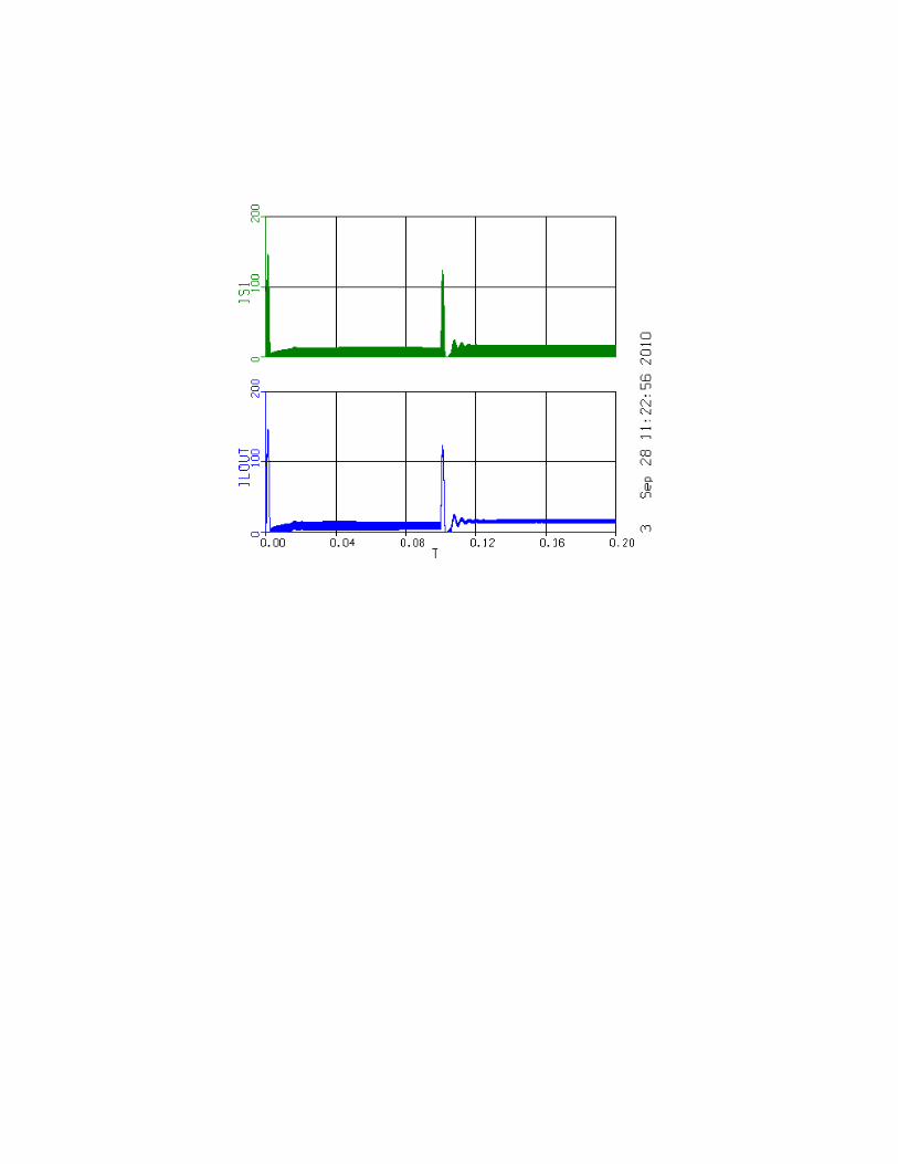
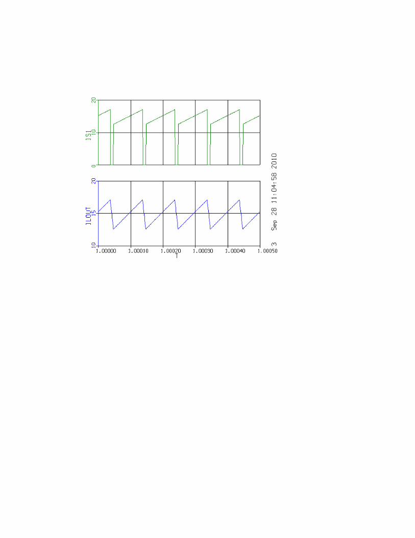
s hvdprn=.f. prepare t,vin,vout,iin,iout,ilout,is1 proced problem6 s d=0.9 s tstop=1.0 s cint=1.0e-4 start s tstop=1.0005 s cint=1.0e-6 s maxt=1.0e-6 contin plot /xlo=1.0/xhi=1.0005 plot vin/lo=498/hi=500,iin/lo=0/hi=20,vout/lo=44 0/hi=450,iout/lo=-15/hi=-14 plot ilout/lo=10/hi=20,is1/lo=0/hi=20 end proced problem7 s d=0.5 action/var=0.1/val=0.9/loc=d start action/clear plot /xlo=0.0/xhi=0.2 plot vin,iin,vout,iout plot ilout,is1 end
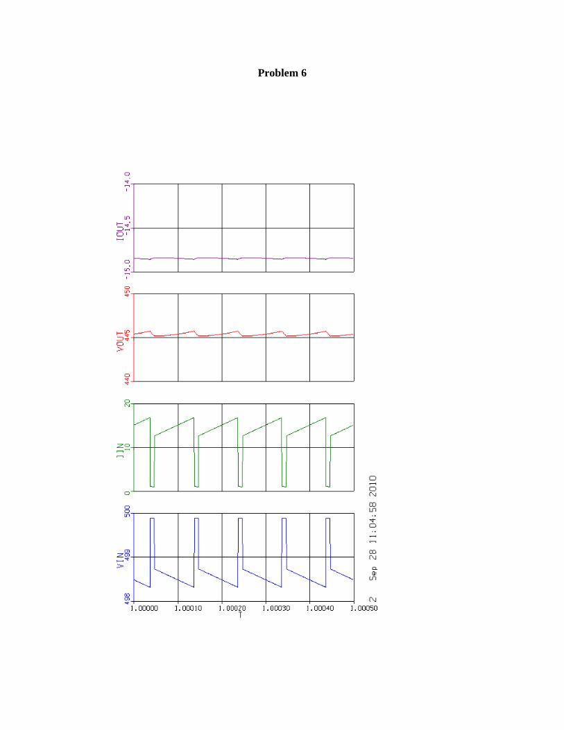
Problem 6
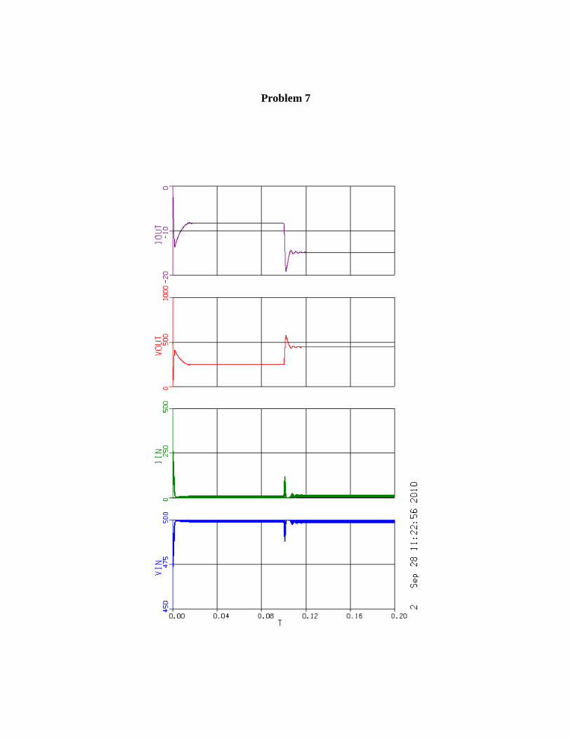
Problem 7