Embed Size (px)
Citation preview

George Mason University
VHDL Basics
Lecture 3
Simple Testbenches
2
Required reading
• P. Chu, RTL Hardware Design using VHDL
Chapter 2, Overview of Hardware Description Languages Chapter 3, Basic Language Constructs of VHDL
3
Recommended reading
• Wikipedia – The Free On-line Encyclopedia VHDL - http://en.wikipedia.org/wiki/VHDL Verilog - http://en.wikipedia.org/wiki/Verilog
Accellera - http://en.wikipedia.org/wiki/Accellera
4
Steps of the Design Process
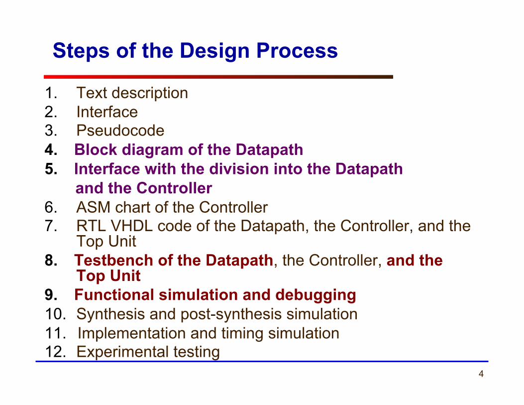
1. Text description 2. Interface 3. Pseudocode 4. Block diagram of the Datapath 5. Interface with the division into the Datapath and the Controller 6. ASM chart of the Controller 7. RTL VHDL code of the Datapath, the Controller, and the
Top Unit 8. Testbench of the Datapath, the Controller, and the
Top Unit 9. Functional simulation and debugging 10. Synthesis and post-synthesis simulation 11. Implementation and timing simulation 12. Experimental testing
5 ECE 448 – FPGA and ASIC Design with VHDL
Differences between Hardware Description Languages (HDL)
and Traditional Programming Languages (PL)
6
7
8
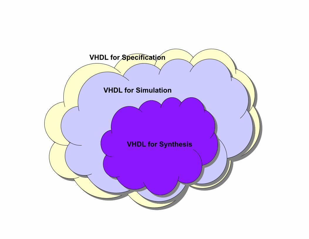
VHDL for Specification
VHDL for Simulation
VHDL for Synthesis

10
11
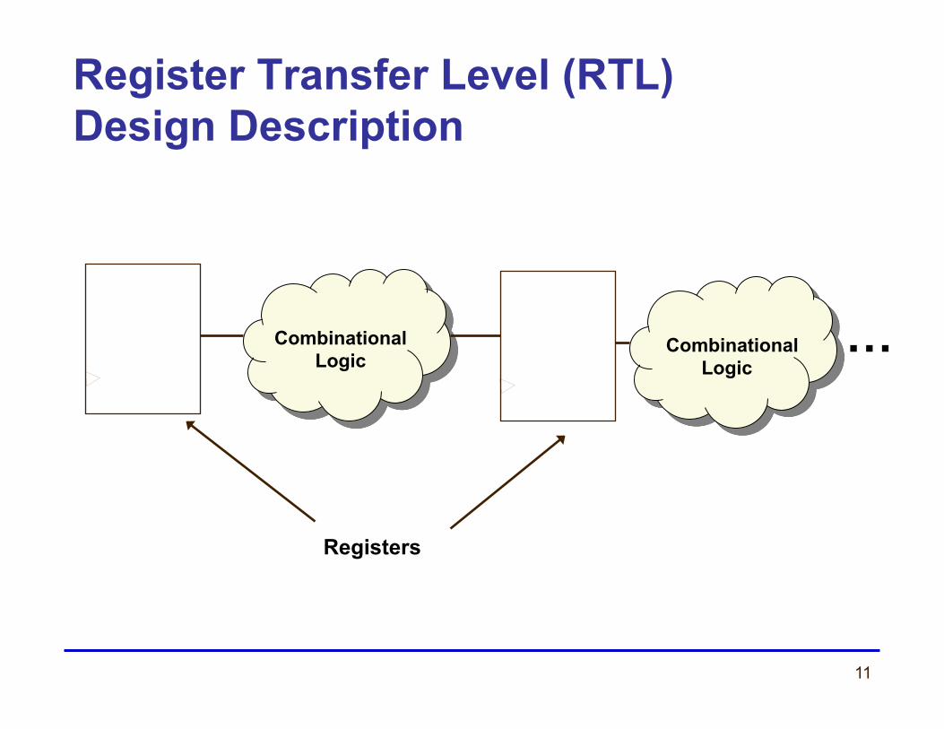
Register Transfer Level (RTL) Design Description
Combinational Logic
Combinational Logic
Registers
…
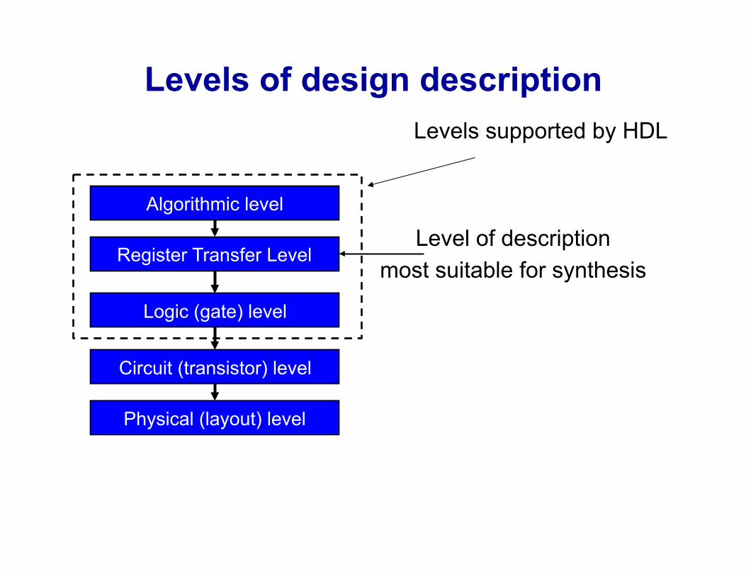
Levels of design description
Algorithmic level
Register Transfer Level
Logic (gate) level
Circuit (transistor) level
Physical (layout) level
Level of description most suitable for synthesis
Levels supported by HDL
13
14 ECE 448 – FPGA and ASIC Design with VHDL
Brief History of VHDL
15
VHDL
• VHDL is a language for describing digital hardware used by industry worldwide
• VHDL is an acronym for VHSIC (Very High Speed Integrated Circuit) Hardware Description Language

16
Genesis of VHDL
• Multiple design entry methods and hardware description languages in use • No or limited portability of designs between CAD tools from different vendors • Objective: shortening the time from a
design concept to implementation from 18 months to 6 months
State of art circa 1980
17
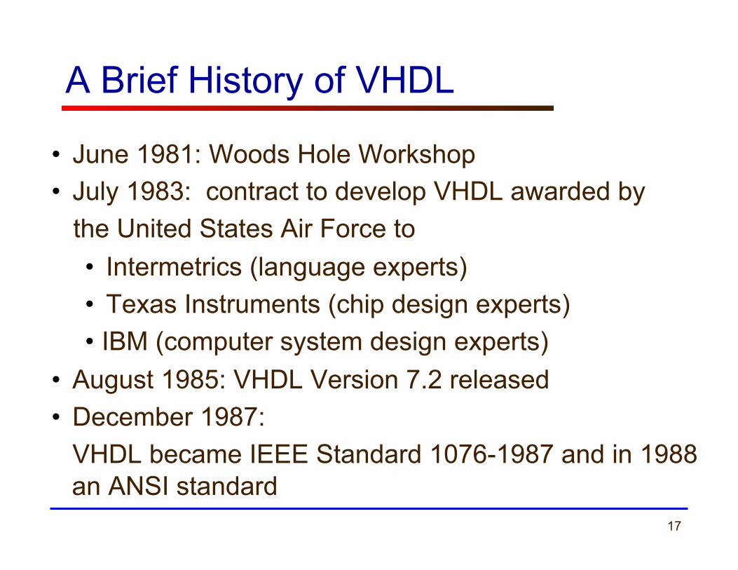
A Brief History of VHDL
• June 1981: Woods Hole Workshop • July 1983: contract to develop VHDL awarded by the United States Air Force to
• Intermetrics (language experts) • Texas Instruments (chip design experts) • IBM (computer system design experts)
• August 1985: VHDL Version 7.2 released • December 1987: VHDL became IEEE Standard 1076-1987 and in 1988 an ANSI standard
18
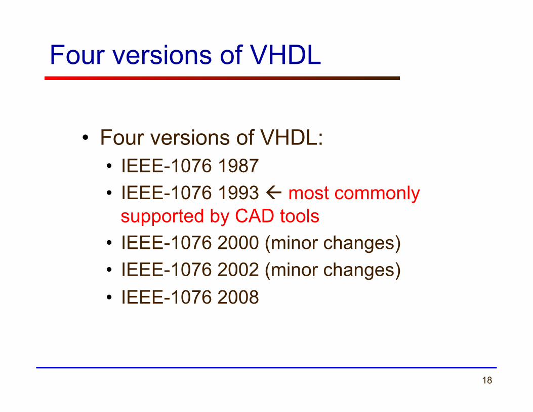
Four versions of VHDL
• Four versions of VHDL: • IEEE-1076 1987 • IEEE-1076 1993 ß most commonly
supported by CAD tools • IEEE-1076 2000 (minor changes) • IEEE-1076 2002 (minor changes) • IEEE-1076 2008
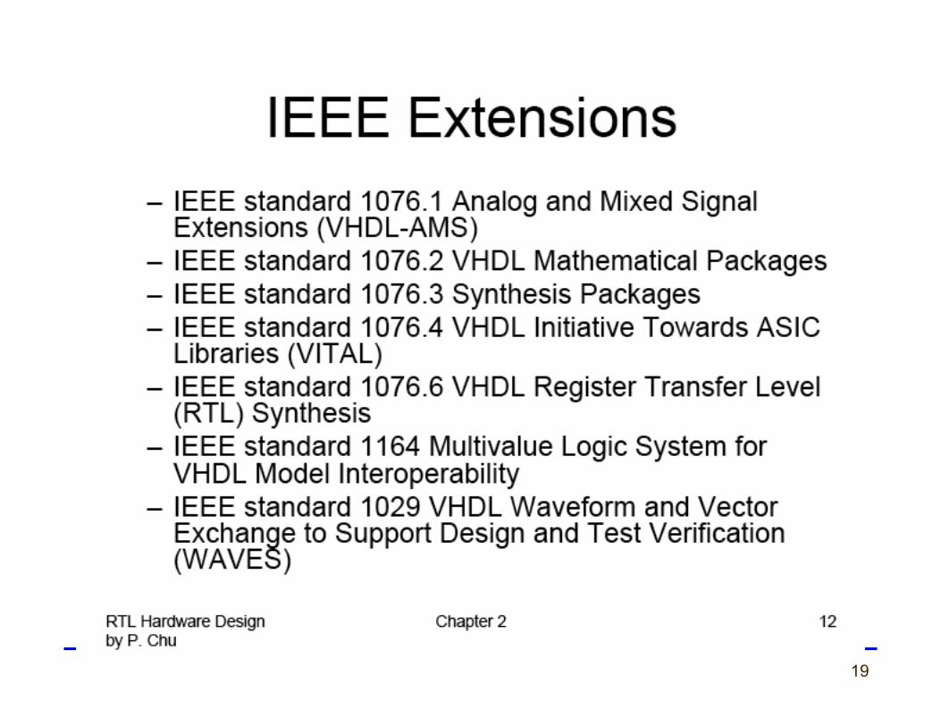
19
20 ECE 448 – FPGA and ASIC Design with VHDL
Verilog
21
Verilog • Essentially identical in function to VHDL • Simpler and syntactically different
• C-like
• Gateway Design Automation Co., 1985 • Gateway acquired by Cadence in 1990 • IEEE Standard 1364-1995 (Verilog-95) • Early de facto standard for ASIC design • Two subsequent versions
• Verilog 2001 (major extensions) ← dominant version used in industry
• Verilog 2005 (minor changes) • Programming language interface to allow connection to
non-Verilog code

22
VHDL vs. Verilog
Government Developed
Commercially Developed
Ada based C based
Strongly Type Cast Mildly Type Cast
Case-insensitive Case-sensitive
Difficult to learn Easier to Learn
More Powerful Less Powerful

23
How to learn Verilog by yourself ?
24
How to learn Verilog by yourself ?
25
Features of VHDL and Verilog
• Technology/vendor independent
• Portable
• Reusable
26 ECE 448 – FPGA and ASIC Design with VHDL
VHDL Fundamentals
27
Naming and Labeling (1)
• VHDL is case insensitive Example:
Names or labels databus Databus DataBus DATABUS
are all equivalent
28
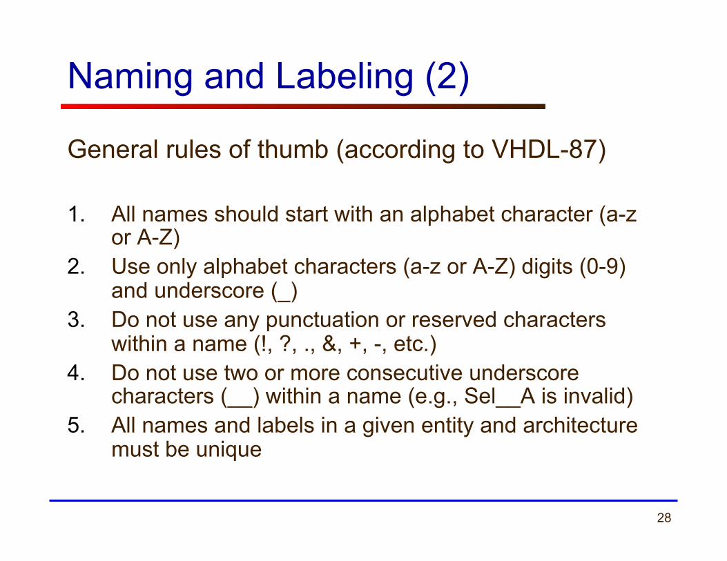
Naming and Labeling (2)
General rules of thumb (according to VHDL-87) 1. All names should start with an alphabet character (a-z
or A-Z) 2. Use only alphabet characters (a-z or A-Z) digits (0-9)
and underscore (_) 3. Do not use any punctuation or reserved characters
within a name (!, ?, ., &, +, -, etc.) 4. Do not use two or more consecutive underscore
characters (__) within a name (e.g., Sel__A is invalid) 5. All names and labels in a given entity and architecture
must be unique

29
Valid or invalid?
7segment_display A87372477424 Adder/Subtractor /reset And_or_gate AND__OR__NOT Kogge-Stone-Adder Ripple&Carry_Adder My adder
30
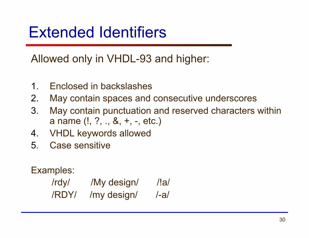
Extended Identifiers Allowed only in VHDL-93 and higher: 1. Enclosed in backslashes 2. May contain spaces and consecutive underscores 3. May contain punctuation and reserved characters within
a name (!, ?, ., &, +, -, etc.) 4. VHDL keywords allowed 5. Case sensitive
Examples: /rdy/ /My design/ /!a/ /RDY/ /my design/ /-a/

31
Free Format
• VHDL is a “free format” language No formatting conventions, such as spacing or
indentation imposed by VHDL compilers. Space and carriage return treated the same way. Example:
if (a=b) then
or if (a=b) then
or if (a =
b) then
are all equivalent
32
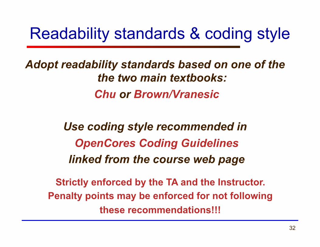
Readability standards & coding style
Adopt readability standards based on one of the the two main textbooks:
Chu or Brown/Vranesic
Use coding style recommended in OpenCores Coding Guidelines
linked from the course web page
Strictly enforced by the TA and the Instructor. Penalty points may be enforced for not following
these recommendations!!!

33
Comments
• Comments in VHDL are indicated with a “double dash”, i.e., “--”
§ Comment indicator can be placed anywhere in the line
§ Any text that follows in the same line is treated as a comment § Carriage return terminates a comment § No method for commenting a block extending over
a couple of lines Examples: -- main subcircuit Data_in <= Data_bus; -- reading data from the input FIFO
34
Comments
• Explain Function of Module to Other Designers
• Explanatory, Not Just Restatement of Code • Locate Close to Code Described
• Put near executable code, not just in a header

35 ECE 448 – FPGA and ASIC Design with VHDL
Design Entity

36
Example: NAND Gate
a b z 0 0 1 0 1 1 1 0 1 1 1 0
a
b z
37
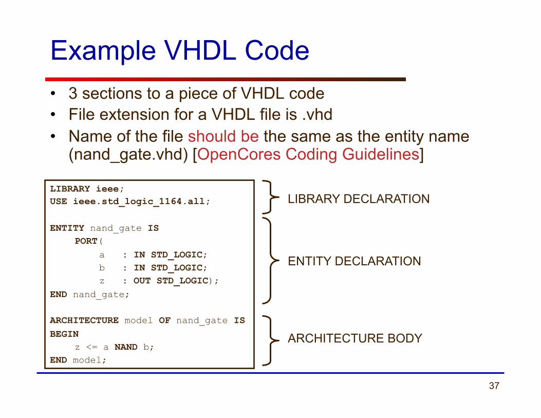
Example VHDL Code • 3 sections to a piece of VHDL code • File extension for a VHDL file is .vhd • Name of the file should be the same as the entity name
(nand_gate.vhd) [OpenCores Coding Guidelines]
LIBRARY DECLARATION
ENTITY DECLARATION
ARCHITECTURE BODY
LIBRARY ieee; USE ieee.std_logic_1164.all; ENTITY nand_gate IS
PORT( a : IN STD_LOGIC; b : IN STD_LOGIC; z : OUT STD_LOGIC);
END nand_gate; ARCHITECTURE model OF nand_gate IS BEGIN
z <= a NAND b; END model;

38
Design Entity - most basic building block of a design.
One entity can have many
different architectures.
entity declaration
architecture 1
architecture 2
architecture 3
design entity
Design Entity

39
ENTITY nand_gate IS PORT( a : IN STD_LOGIC;
b : IN STD_LOGIC; z : OUT STD_LOGIC
); END nand_gate;
Reserved words
Entity name Port names Port type Semicolon
No Semicolon after last port
Port modes (data flow directions)
Entity Declaration
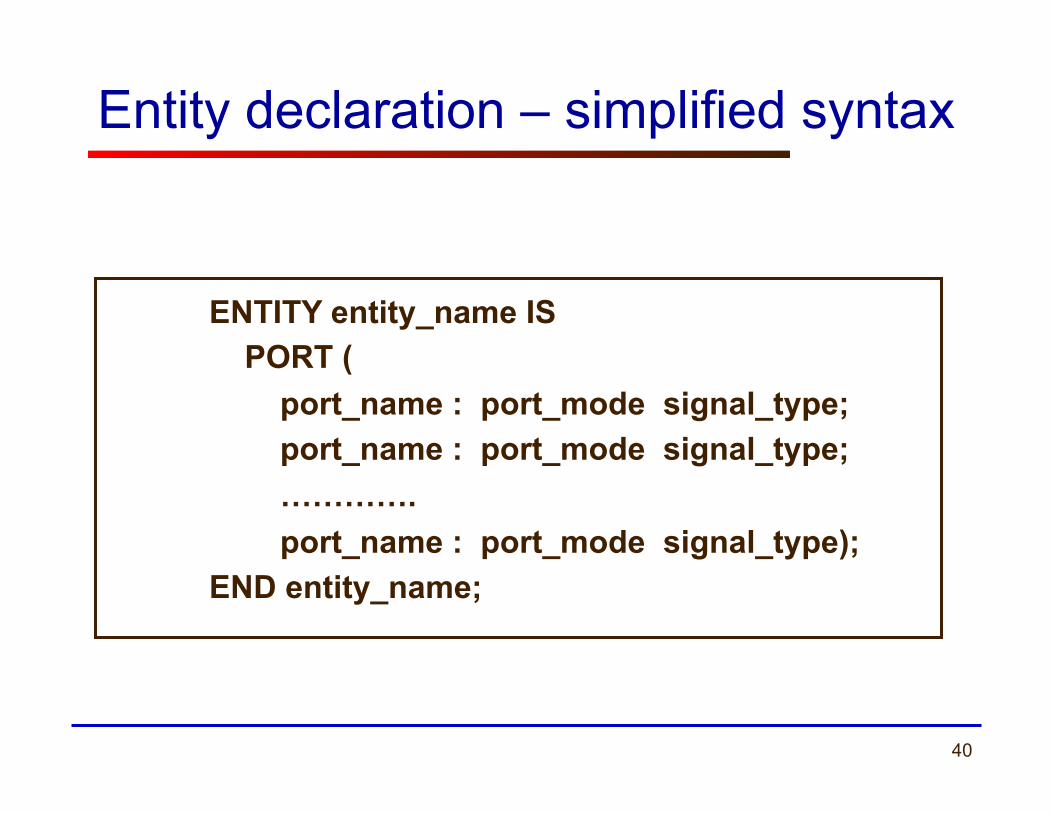
• Entity Declaration describes the interface of the component, i.e. input and output ports.
40
ENTITY entity_name IS PORT ( port_name : port_mode signal_type; port_name : port_mode signal_type; …………. port_name : port_mode signal_type); END entity_name;
Entity declaration – simplified syntax
41
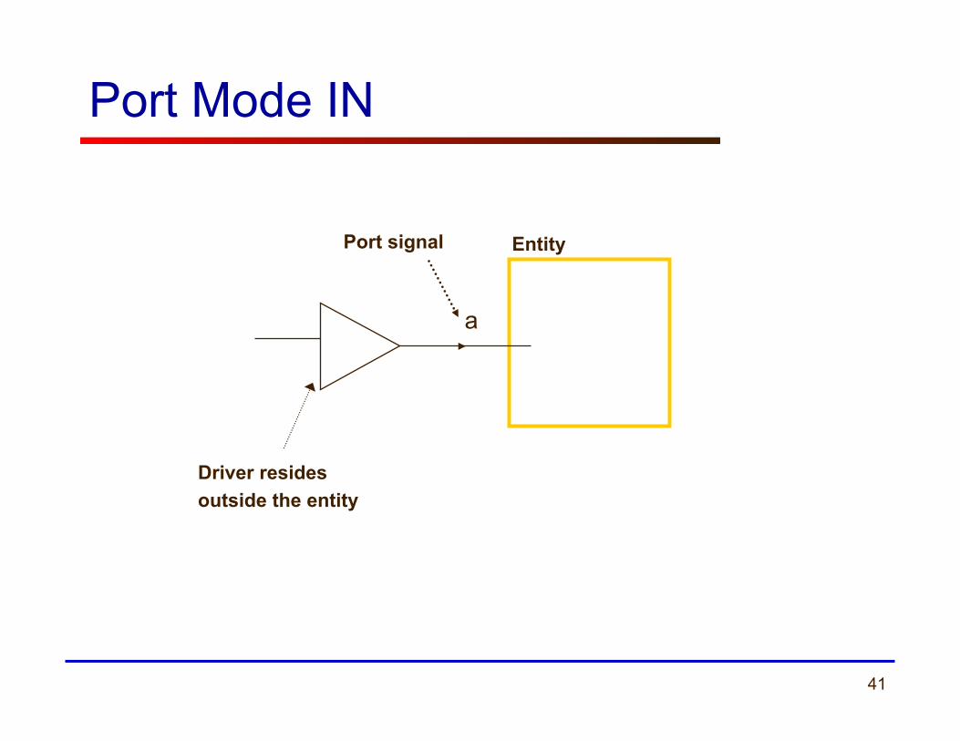
a
Entity Port signal
Driver resides outside the entity
Port Mode IN

42
Entity
Port signal
Driver resides inside the entity
Output cannot be read within the entity
z
c <= z
c
Port Mode OUT
43
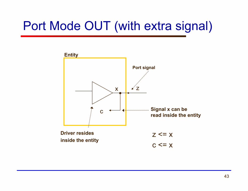
Port signal
Entity
Driver resides inside the entity
Signal x can be read inside the entity
x
c
z
z <= x c <= x
Port Mode OUT (with extra signal)

44
Signal can be read inside the entity
Entity Port signal
Driver may reside both inside and outside of the entity
a
Port Mode INOUT (typically avoided)
45
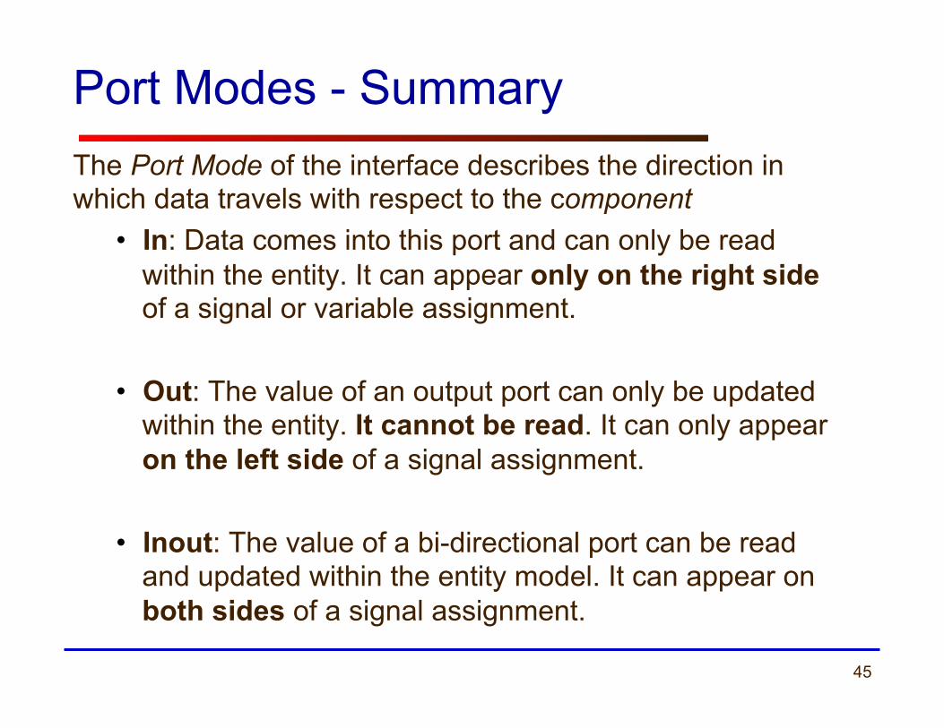
Port Modes - Summary The Port Mode of the interface describes the direction in which data travels with respect to the component
• In: Data comes into this port and can only be read within the entity. It can appear only on the right side of a signal or variable assignment.
• Out: The value of an output port can only be updated within the entity. It cannot be read. It can only appear on the left side of a signal assignment.
• Inout: The value of a bi-directional port can be read and updated within the entity model. It can appear on both sides of a signal assignment.
46
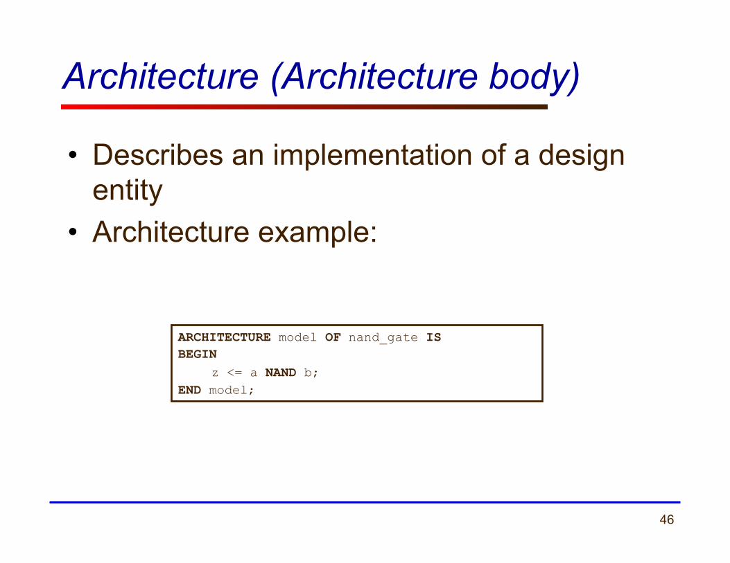
Architecture (Architecture body)
• Describes an implementation of a design entity
• Architecture example:
ARCHITECTURE model OF nand_gate IS BEGIN
z <= a NAND b; END model;
47
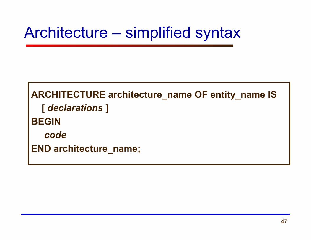
Architecture – simplified syntax
ARCHITECTURE architecture_name OF entity_name IS [ declarations ] BEGIN code END architecture_name;
48
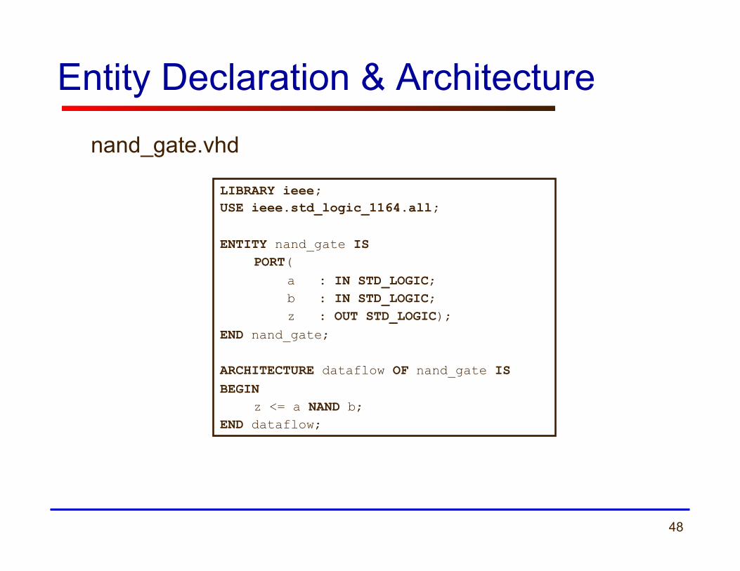
Entity Declaration & Architecture
LIBRARY ieee; USE ieee.std_logic_1164.all; ENTITY nand_gate IS
PORT( a : IN STD_LOGIC; b : IN STD_LOGIC; z : OUT STD_LOGIC);
END nand_gate; ARCHITECTURE dataflow OF nand_gate IS BEGIN
z <= a NAND b; END dataflow;
nand_gate.vhd
49
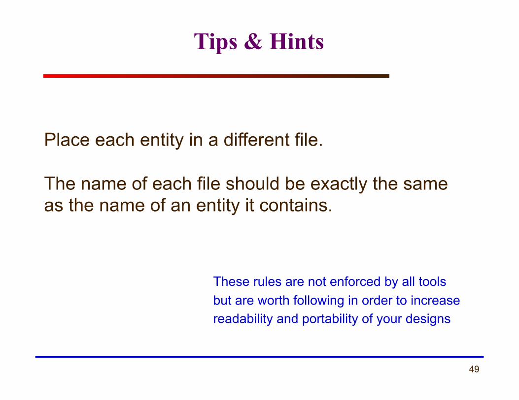
Tips & Hints
Place each entity in a different file. The name of each file should be exactly the same as the name of an entity it contains.
These rules are not enforced by all tools but are worth following in order to increase readability and portability of your designs
50
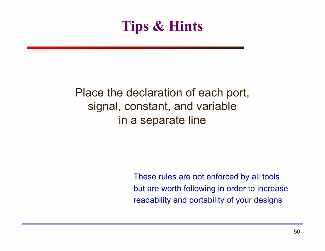
Tips & Hints
Place the declaration of each port, signal, constant, and variable
in a separate line
These rules are not enforced by all tools but are worth following in order to increase readability and portability of your designs

51 ECE 448 – FPGA and ASIC Design with VHDL
Libraries
52
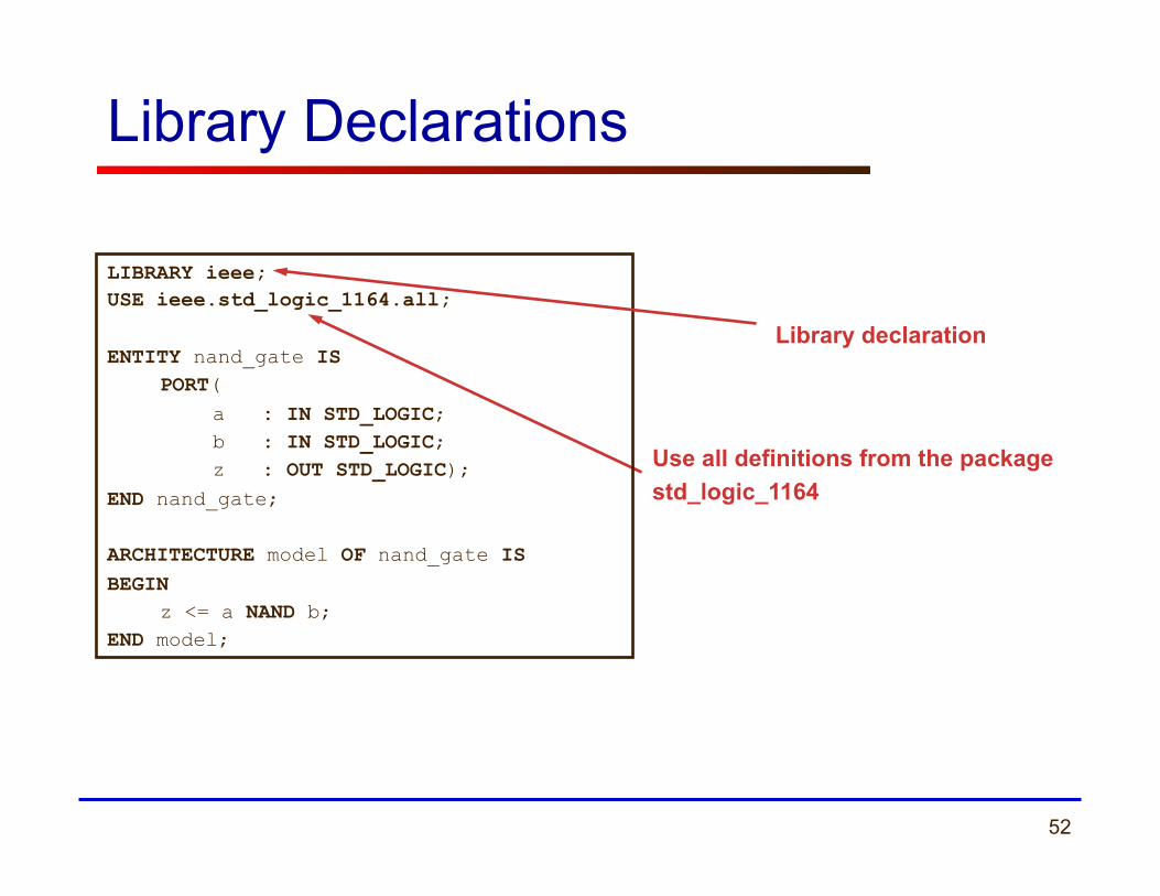
Library Declarations
Use all definitions from the package std_logic_1164
LIBRARY ieee; USE ieee.std_logic_1164.all; ENTITY nand_gate IS
PORT( a : IN STD_LOGIC; b : IN STD_LOGIC; z : OUT STD_LOGIC);
END nand_gate; ARCHITECTURE model OF nand_gate IS BEGIN
z <= a NAND b; END model;
Library declaration
53
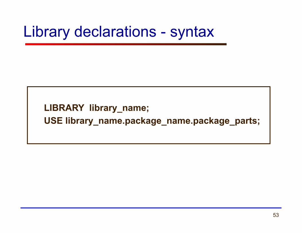
Library declarations - syntax
LIBRARY library_name; USE library_name.package_name.package_parts;

54
Fundamental parts of a library
LIBRARY
PACKAGE 1 PACKAGE 2
TYPES CONSTANTS FUNCTIONS PROCEDURES COMPONENTS
TYPES CONSTANTS FUNCTIONS PROCEDURES COMPONENTS
55
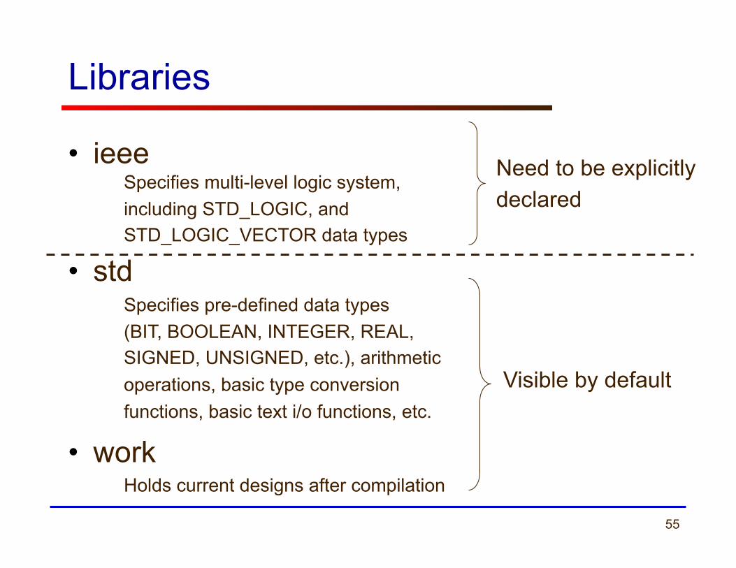
Libraries
• ieee
• std
• work
Need to be explicitly declared
Visible by default
Specifies multi-level logic system, including STD_LOGIC, and STD_LOGIC_VECTOR data types
Specifies pre-defined data types (BIT, BOOLEAN, INTEGER, REAL, SIGNED, UNSIGNED, etc.), arithmetic operations, basic type conversion functions, basic text i/o functions, etc.
Holds current designs after compilation
56 ECE 448 – FPGA and ASIC Design with VHDL
STD_LOGIC Demystified

57
STD_LOGIC
What is STD_LOGIC you ask?
LIBRARY ieee; USE ieee.std_logic_1164.all; ENTITY nand_gate IS
PORT( a : IN STD_LOGIC; b : IN STD_LOGIC; z : OUT STD_LOGIC);
END nand_gate; ARCHITECTURE dataflow OF nand_gate IS BEGIN
z <= a NAND b; END dataflow;
58
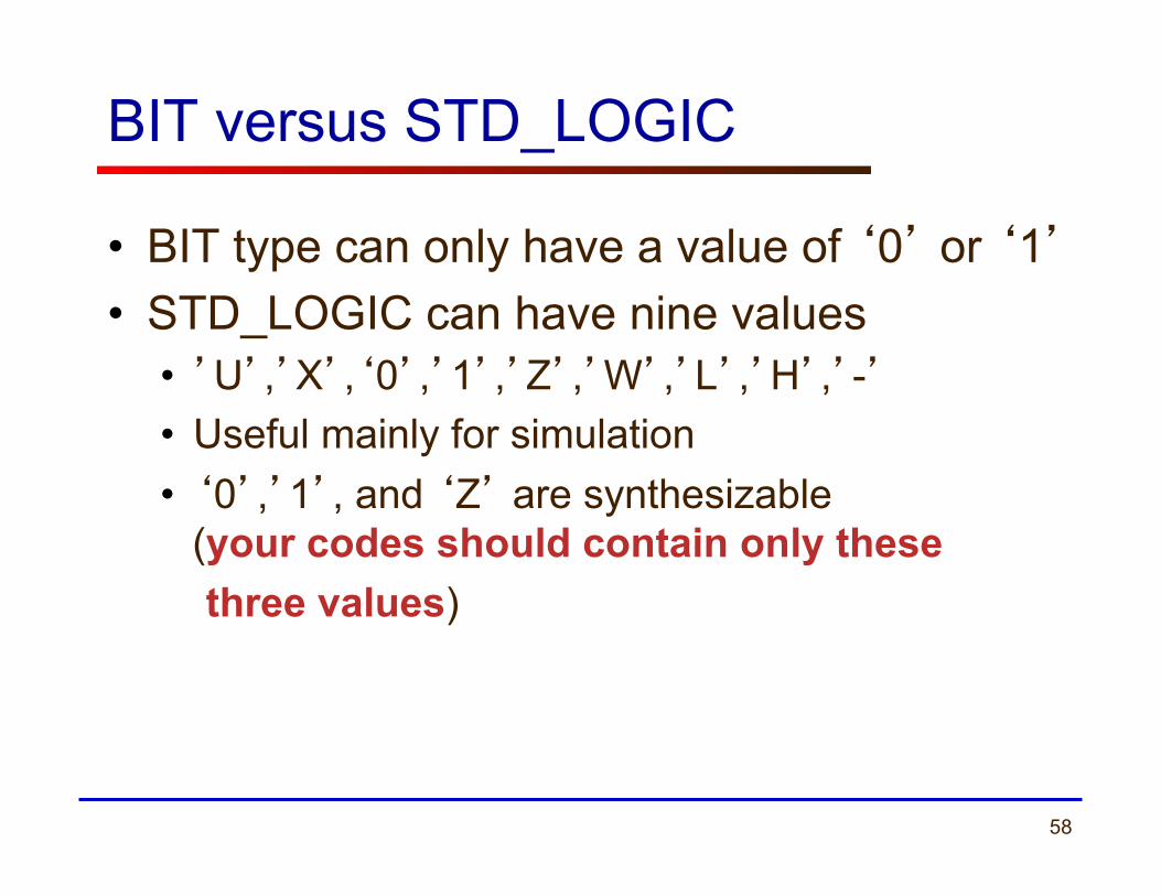
BIT versus STD_LOGIC
• BIT type can only have a value of ‘0’ or ‘1’ • STD_LOGIC can have nine values
• ’U’,’X’,‘0’,’1’,’Z’,’W’,’L’,’H’,’-’ • Useful mainly for simulation • ‘0’,’1’, and ‘Z’ are synthesizable
(your codes should contain only these three values)
59
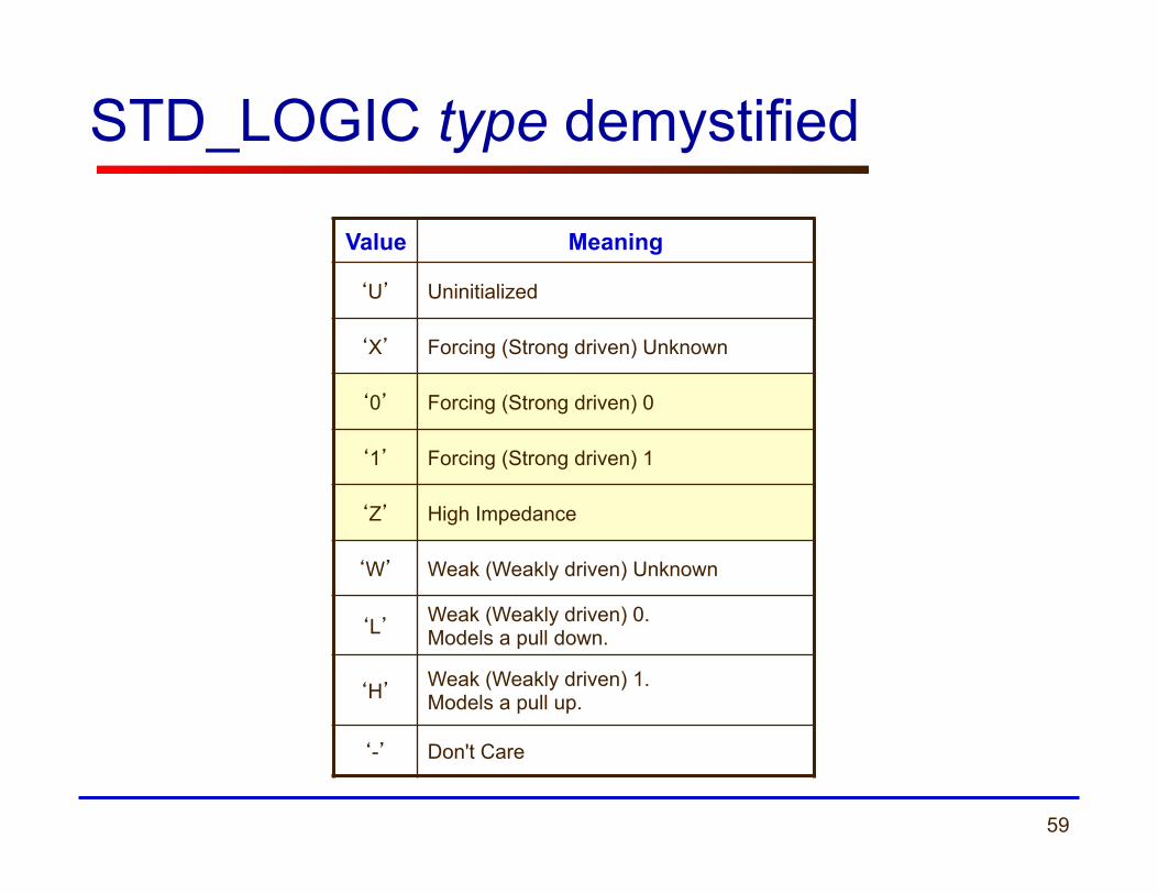
STD_LOGIC type demystified
Value Meaning
‘U’ Uninitialized
‘X’ Forcing (Strong driven) Unknown
‘0’ Forcing (Strong driven) 0
‘1’ Forcing (Strong driven) 1
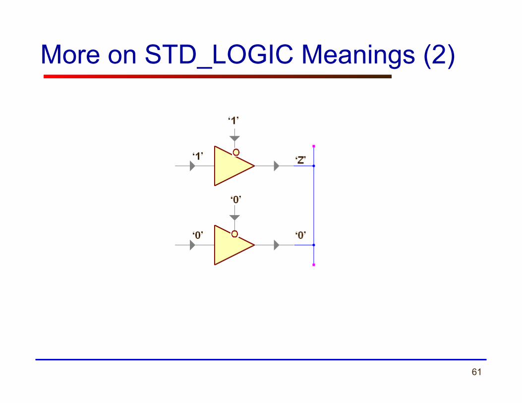
‘Z’ High Impedance
‘W’ Weak (Weakly driven) Unknown
‘L’ Weak (Weakly driven) 0. Models a pull down.
‘H’ Weak (Weakly driven) 1. Models a pull up.
‘-’ Don't Care
60
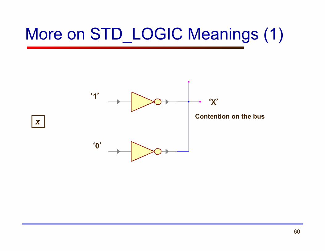
More on STD_LOGIC Meanings (1)
‘1’
‘0’
‘X’
Contention on the bus X
61
More on STD_LOGIC Meanings (2)
62
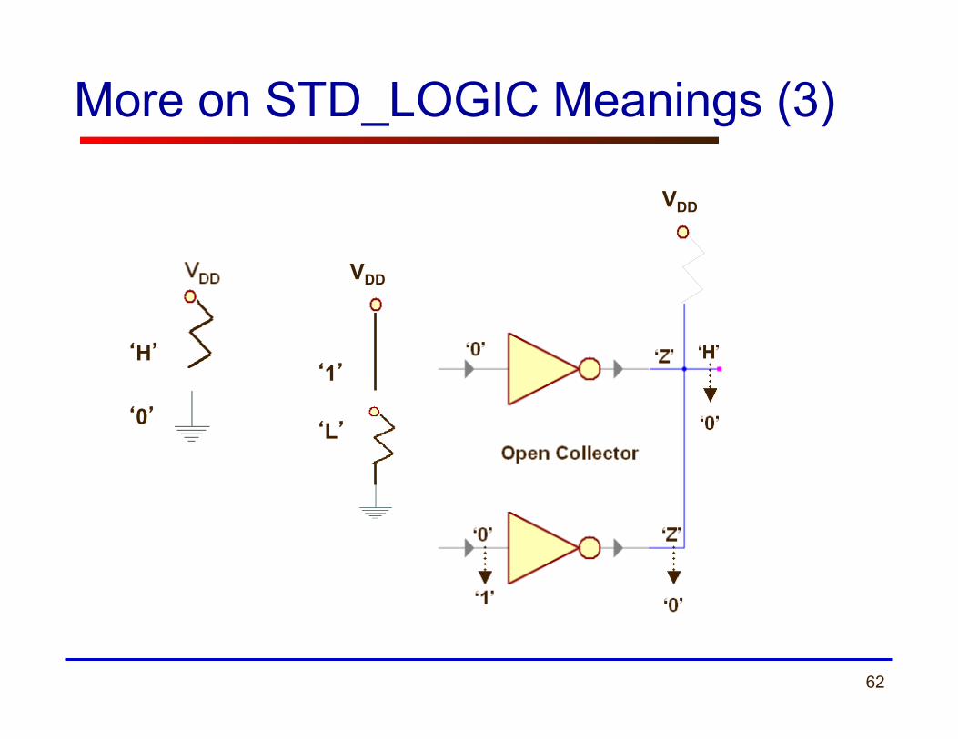
VDD
‘H’
‘0’
‘1’
‘L’
More on STD_LOGIC Meanings (3)
VDD

63
More on STD_LOGIC Meanings (4)
• Do not care. • Can be assigned to outputs for the case of invalid inputs (may produce significant improvement in resource utilization after synthesis). • Must be used with great caution. For example in VHDL, the direct comparison ‘1’ = ‘-’ gives FALSE. The "std_match" functions defined in the numeric_std package must be used to make this value work as expected: Example: if (std_match(address, "-11---") then ... elsif (std_match(address, "-01---") then ... else ... end if;
‘-’

64
Resolving logic levels
U X 0 1 Z W L H - U U U U U U U U U U X U X X X X X X X X 0 U X 0 X 0 0 0 0 X 1 U X X 1 1 1 1 1 X Z U X 0 1 Z W L H X W U X 0 1 W W W W X L U X 0 1 L W L W X H U X 0 1 H W W H X - U X X X X X X X X
65
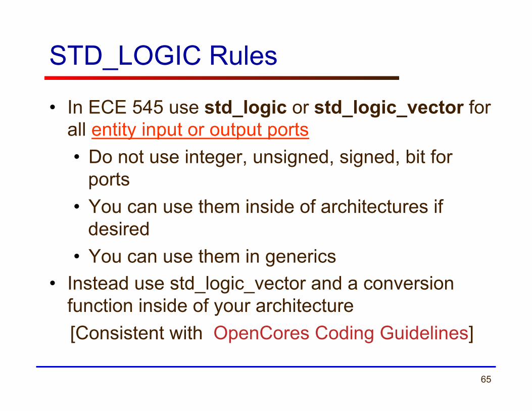
STD_LOGIC Rules
• In ECE 545 use std_logic or std_logic_vector for all entity input or output ports • Do not use integer, unsigned, signed, bit for
ports • You can use them inside of architectures if
desired • You can use them in generics
• Instead use std_logic_vector and a conversion function inside of your architecture
[Consistent with OpenCores Coding Guidelines]
66 ECE 448 – FPGA and ASIC Design with VHDL
Modeling Wires and Buses

67
Signals
SIGNAL a : STD_LOGIC;
SIGNAL b : STD_LOGIC_VECTOR(7 DOWNTO 0);
wire
a
bus
b
1
8
68
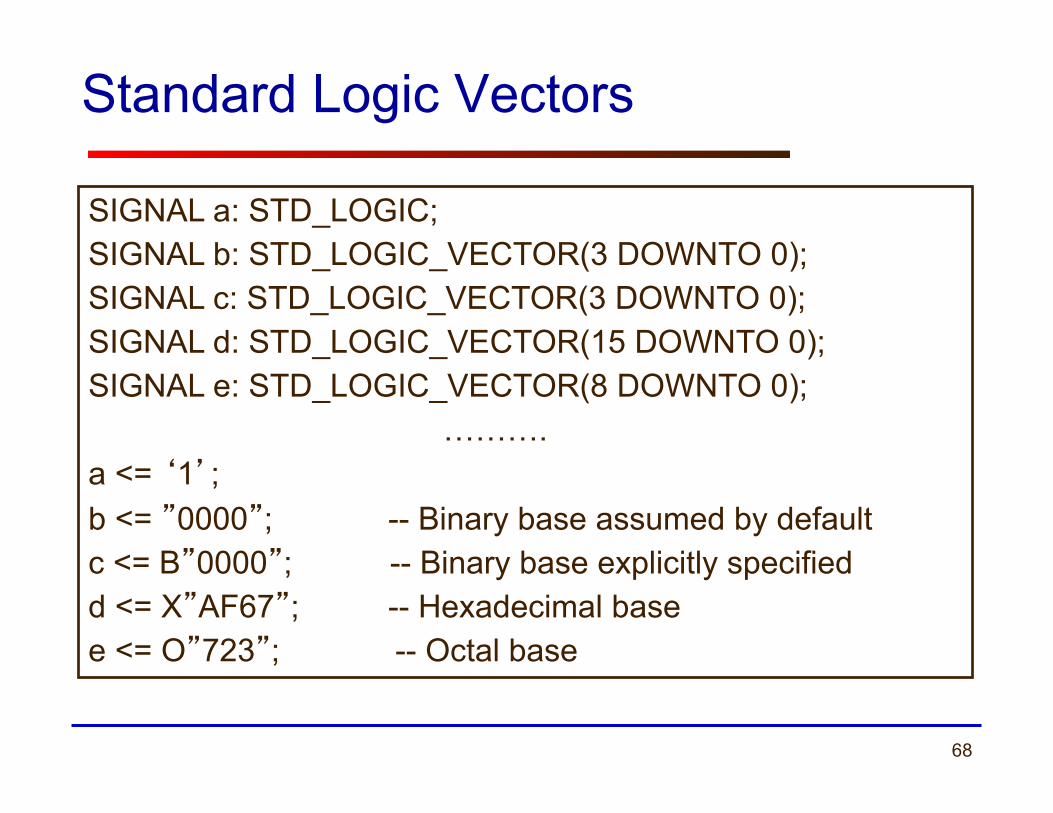
Standard Logic Vectors
SIGNAL a: STD_LOGIC; SIGNAL b: STD_LOGIC_VECTOR(3 DOWNTO 0); SIGNAL c: STD_LOGIC_VECTOR(3 DOWNTO 0); SIGNAL d: STD_LOGIC_VECTOR(15 DOWNTO 0); SIGNAL e: STD_LOGIC_VECTOR(8 DOWNTO 0); ………. a <= ‘1’; b <= ”0000”; -- Binary base assumed by default c <= B”0000”; -- Binary base explicitly specified d <= X”AF67”; -- Hexadecimal base e <= O”723”; -- Octal base
69
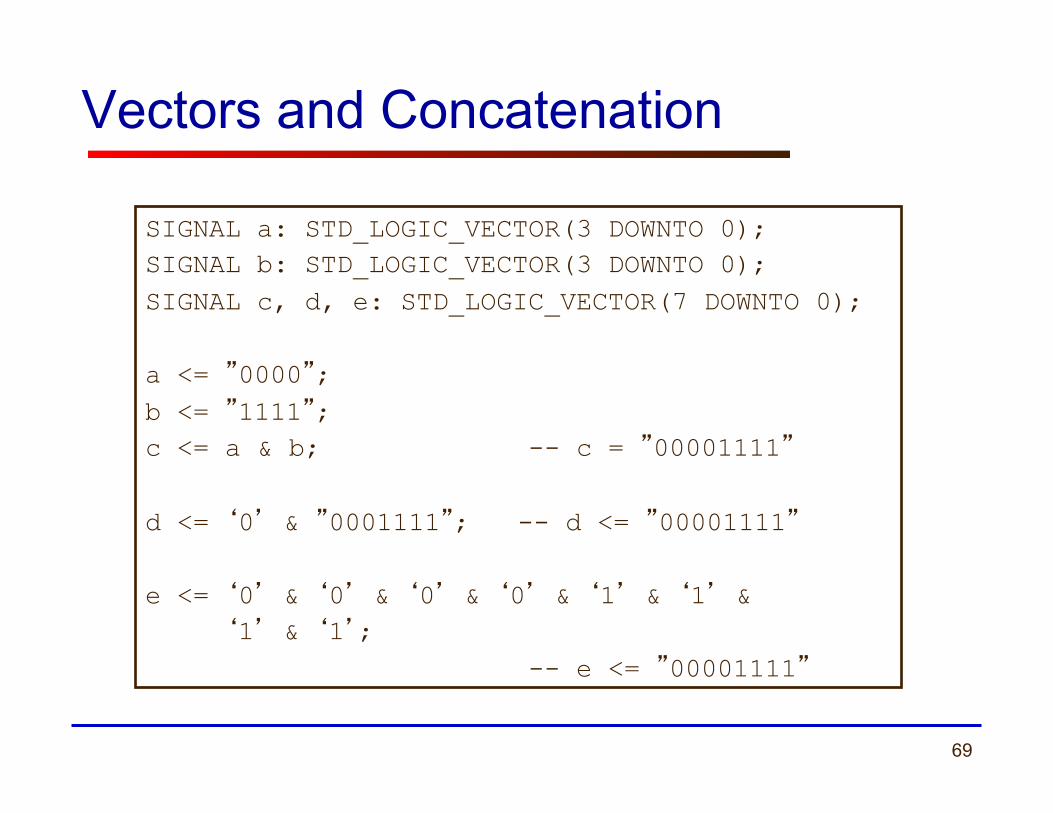
Vectors and Concatenation
SIGNAL a: STD_LOGIC_VECTOR(3 DOWNTO 0); SIGNAL b: STD_LOGIC_VECTOR(3 DOWNTO 0); SIGNAL c, d, e: STD_LOGIC_VECTOR(7 DOWNTO 0); a <= ”0000”; b <= ”1111”; c <= a & b; -- c = ”00001111” d <= ‘0’ & ”0001111”; -- d <= ”00001111” e <= ‘0’ & ‘0’ & ‘0’ & ‘0’ & ‘1’ & ‘1’ & ‘1’ & ‘1’; -- e <= ”00001111”
70 ECE 448 – FPGA and ASIC Design with VHDL
Types of VHDL Description (Modeling Styles)
71
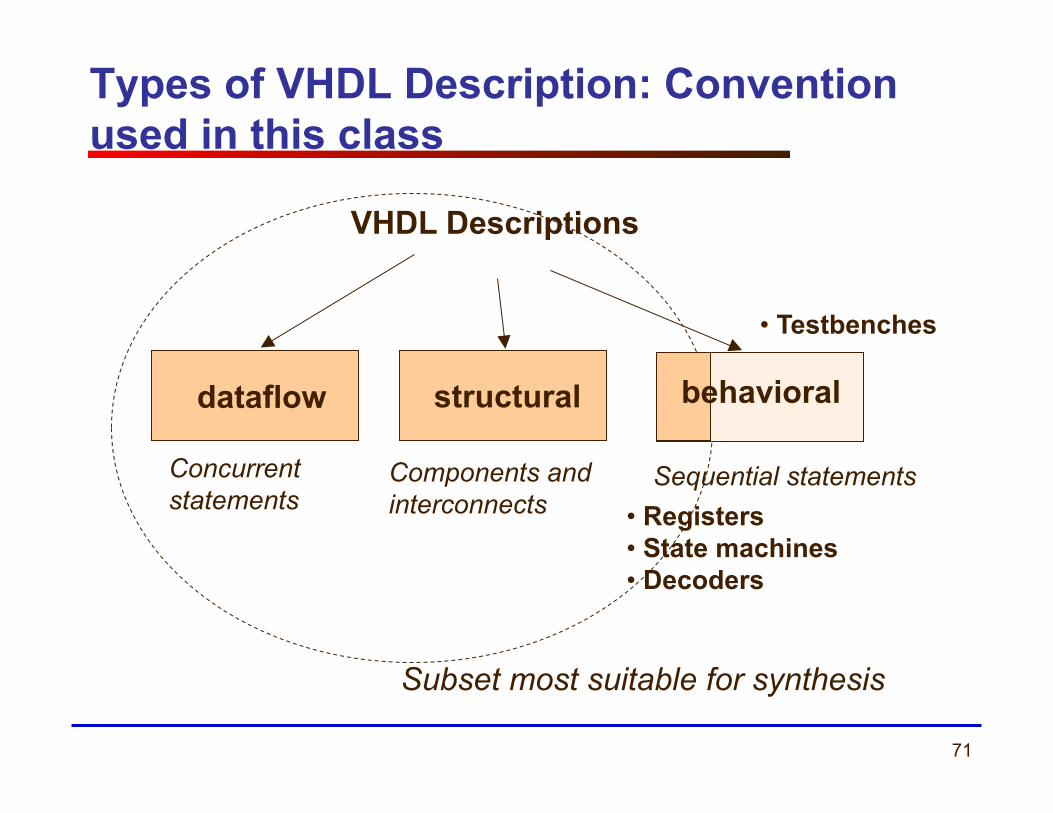
Types of VHDL Description: Convention used in this class
Components and interconnects
structural
VHDL Descriptions
dataflow
Concurrent statements
behavioral
• Registers • State machines • Decoders
Sequential statements
Subset most suitable for synthesis
• Testbenches
72
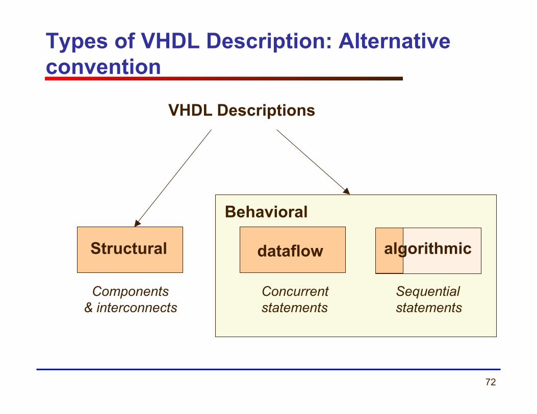
Types of VHDL Description: Alternative convention
Components & interconnects
Structural
VHDL Descriptions
dataflow
Concurrent statements
algorithmic
Sequential statements
Behavioral
73
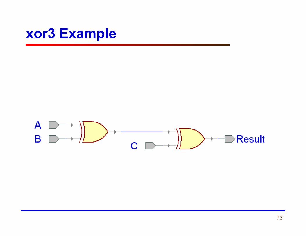
xor3 Example

74
Entity xor3_gate
LIBRARY ieee; USE ieee.std_logic_1164.all; ENTITY xor3_gate IS
PORT( A : IN STD_LOGIC; B : IN STD_LOGIC; C : IN STD_LOGIC; Result : OUT STD_LOGIC );
end xor3_gate;
75
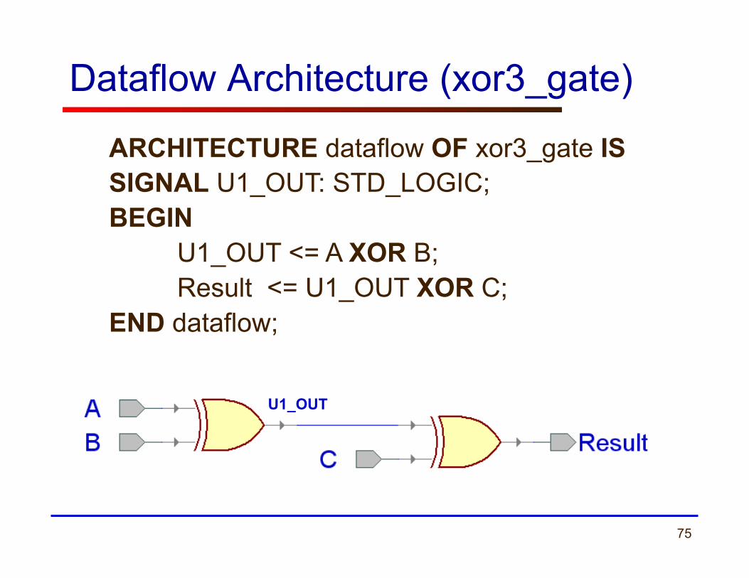
Dataflow Architecture (xor3_gate)
ARCHITECTURE dataflow OF xor3_gate IS SIGNAL U1_OUT: STD_LOGIC; BEGIN
U1_OUT <= A XOR B; Result <= U1_OUT XOR C;
END dataflow;
U1_OUT
76
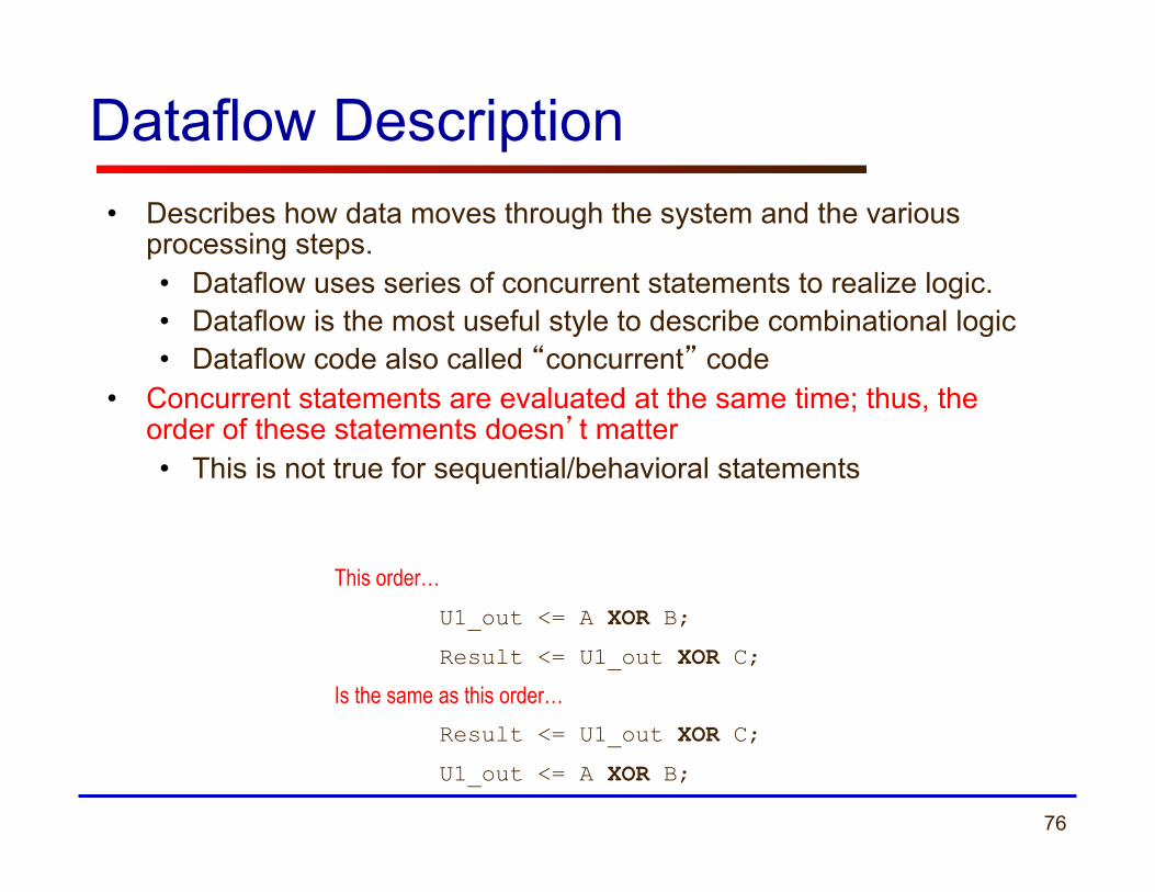
Dataflow Description • Describes how data moves through the system and the various
processing steps. • Dataflow uses series of concurrent statements to realize logic. • Dataflow is the most useful style to describe combinational logic • Dataflow code also called “concurrent” code
• Concurrent statements are evaluated at the same time; thus, the order of these statements doesn’t matter • This is not true for sequential/behavioral statements
This order… U1_out <= A XOR B;
Result <= U1_out XOR C;
Is the same as this order… Result <= U1_out XOR C;
U1_out <= A XOR B;
77
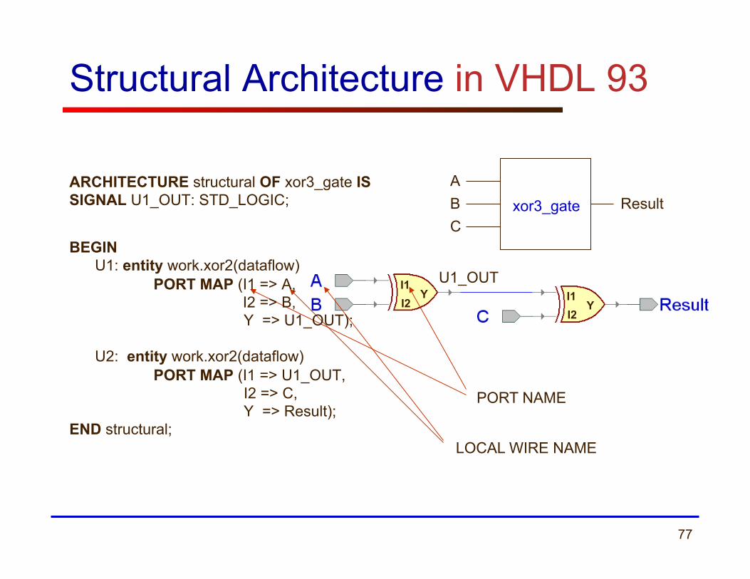
Structural Architecture in VHDL 93
ABC
Result xor3_gate
I1 I2
Y I1 I2
Y
U1_OUT
PORT NAME
LOCAL WIRE NAME
ARCHITECTURE structural OF xor3_gate IS SIGNAL U1_OUT: STD_LOGIC;
BEGIN U1: entity work.xor2(dataflow)
PORT MAP (I1 => A, I2 => B, Y => U1_OUT); U2: entity work.xor2(dataflow)
PORT MAP (I1 => U1_OUT, I2 => C, Y => Result);
END structural;
78
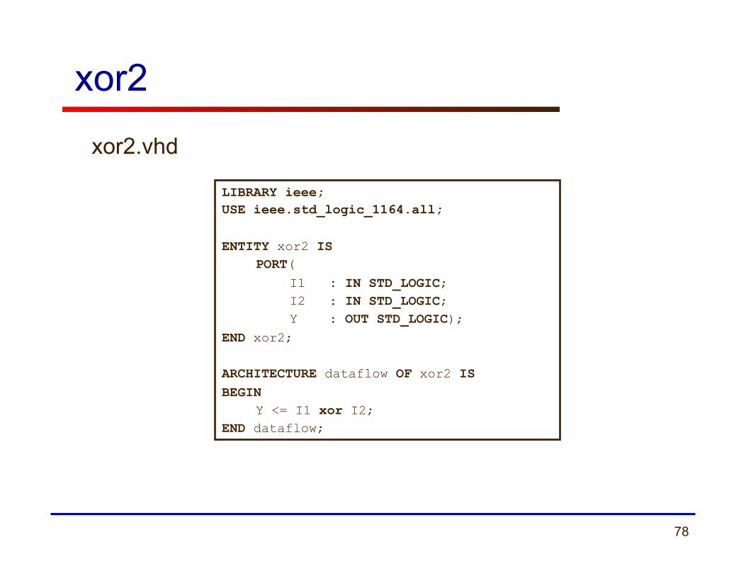
xor2
LIBRARY ieee; USE ieee.std_logic_1164.all; ENTITY xor2 IS
PORT( I1 : IN STD_LOGIC; I2 : IN STD_LOGIC; Y : OUT STD_LOGIC);
END xor2; ARCHITECTURE dataflow OF xor2 IS BEGIN
Y <= I1 xor I2; END dataflow;
xor2.vhd
79
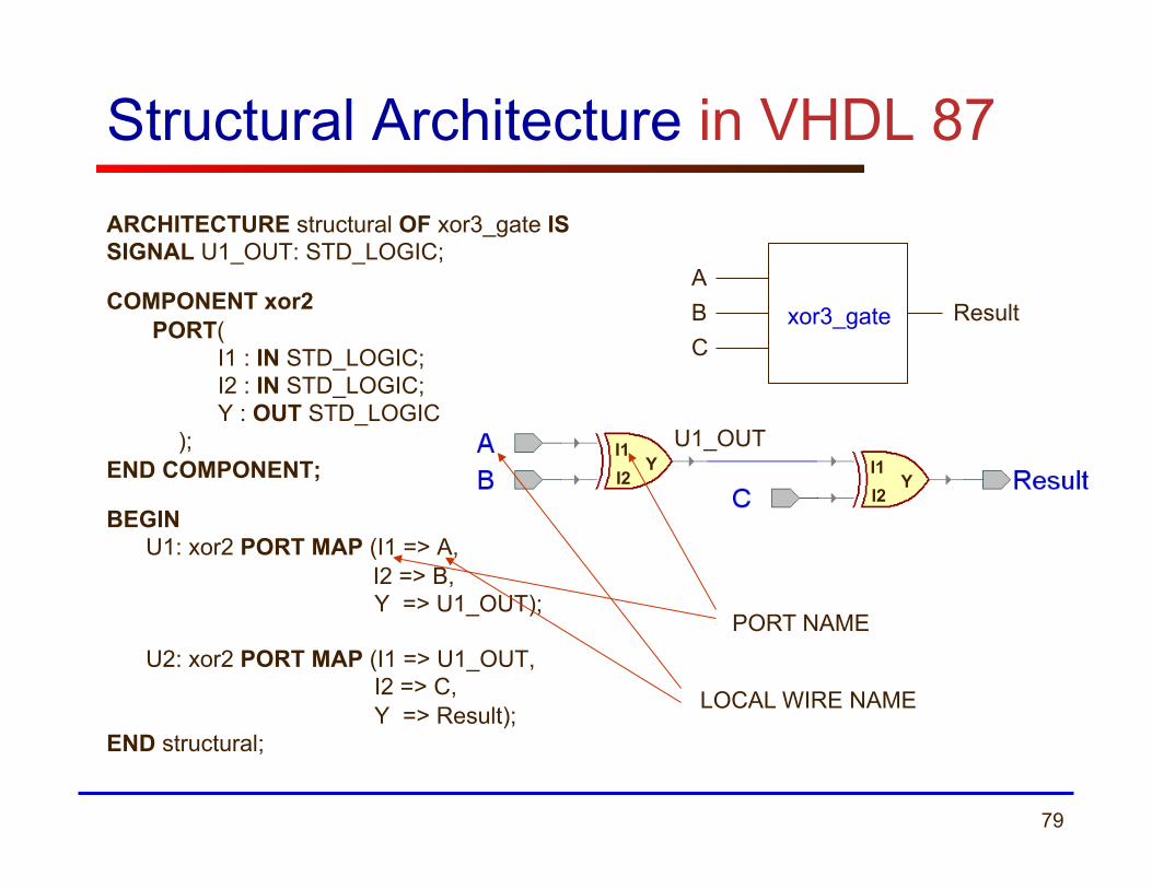
Structural Architecture in VHDL 87 ARCHITECTURE structural OF xor3_gate IS SIGNAL U1_OUT: STD_LOGIC;
COMPONENT xor2
PORT( I1 : IN STD_LOGIC; I2 : IN STD_LOGIC; Y : OUT STD_LOGIC );
END COMPONENT;
BEGIN U1: xor2 PORT MAP (I1 => A, I2 => B, Y => U1_OUT); U2: xor2 PORT MAP (I1 => U1_OUT, I2 => C, Y => Result);
END structural;
ABC
Result xor3_gate
I1 I2
Y I1 I2
Y
U1_OUT
PORT NAME
LOCAL WIRE NAME

80
Structural Description
• Structural design is the simplest to understand. This style is the closest to schematic capture and utilizes simple building blocks to compose logic functions.
• Components are interconnected in a hierarchical manner.
• Structural descriptions may connect simple gates or complex, abstract components.
• Structural style is useful when expressing a design that is naturally composed of sub-blocks.
81
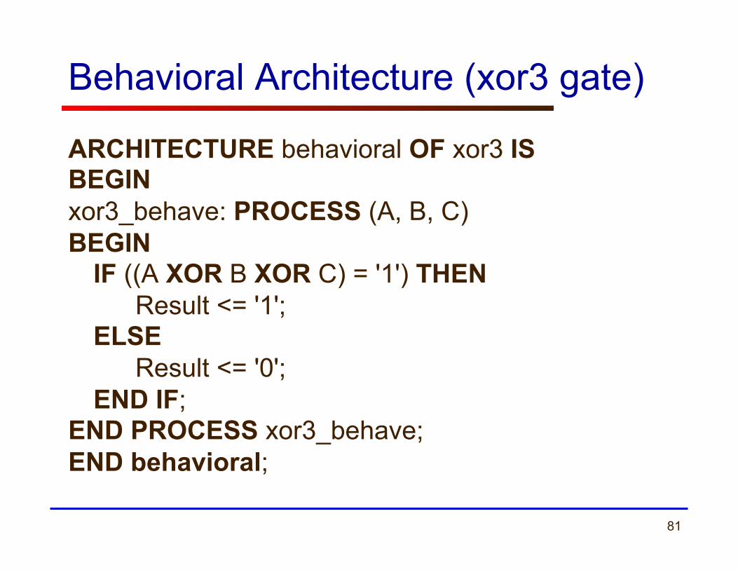
Behavioral Architecture (xor3 gate)
ARCHITECTURE behavioral OF xor3 IS BEGIN xor3_behave: PROCESS (A, B, C) BEGIN
IF ((A XOR B XOR C) = '1') THEN Result <= '1'; ELSE Result <= '0'; END IF;
END PROCESS xor3_behave; END behavioral;
82
Behavioral Description
• It accurately models what happens on the inputs and outputs of the black box (no matter what is inside and how it works).
• This style uses PROCESS statements in VHDL.
83 ECE 448 – FPGA and ASIC Design with VHDL
Testbenches
84
Testbench Defined
• Testbench = VHDL entity that applies stimuli (drives the inputs) to the Design Under Test (DUT) and (optionally) verifies expected outputs.
• The results can be viewed in a waveform window or written to a file.
• Since Testbench is written in VHDL, it is not restricted to a single simulation tool (portability).
• The same Testbench can be easily adapted to test different implementations (i.e. different architectures) of the same design.
85
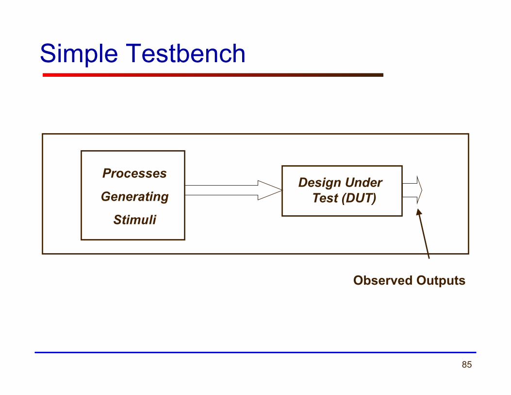
Simple Testbench
Processes
Generating
Stimuli
Design Under Test (DUT)
Observed Outputs

86
Advanced Testbench (1)
Processes Generating
Input Stimuli
Design Under Test (DUT)
Process Comparing
Actual Outputs
vs. Expected
Outputs
Design Correct/Incorrect
Yes/No
87
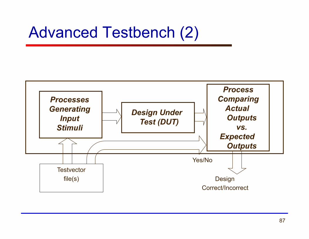
Advanced Testbench (2)
Processes Generating
Input Stimuli
Design Under Test (DUT)
Process Comparing
Actual Outputs
vs. Expected
Outputs
Design Correct/Incorrect
Yes/No Testvector
file(s)

88
Test vectors
Set of pairs: {Input i, Expected Output i} Input 1, Expected Output 1 Input 2, Expected Output 2 …………………………… Input N, Expected Output N
Test vectors can be: - defined in the testbench source file - stored in a data file
89
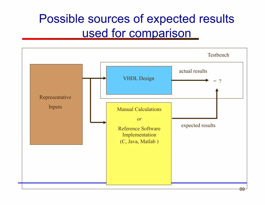
Representative
Inputs
VHDL Design
Manual Calculations
or
Reference Software Implementation
(C, Java, Matlab )
expected results
Testbench
actual results
= ?
Possible sources of expected results used for comparison

90
Testbench
testbench
design entity
Architecture 1 Architecture 2 Architecture N . . . .
The same testbench can be used to test multiple implementations of the same circuit
(multiple architectures)

91
Simple Testbench Anatomy ENTITY my_entity_tb IS
--TB entity has no ports
END my_entity_tb; ARCHITECTURE behavioral OF tb IS --Local signals and constants
----------------------------------------------------- BEGIN DUT: entity work.TestComp(dataflow) PORT MAP( -- Instantiations of DUTs ); testSequence: PROCESS -- Input stimuli END PROCESS; END behavioral;
92
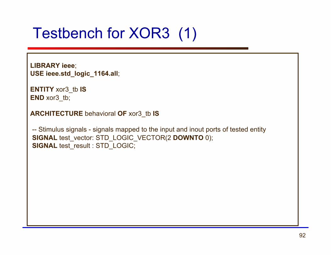
Testbench for XOR3 (1) LIBRARY ieee; USE ieee.std_logic_1164.all; ENTITY xor3_tb IS END xor3_tb; ARCHITECTURE behavioral OF xor3_tb IS -- Stimulus signals - signals mapped to the input and inout ports of tested entity SIGNAL test_vector: STD_LOGIC_VECTOR(2 DOWNTO 0); SIGNAL test_result : STD_LOGIC;
93
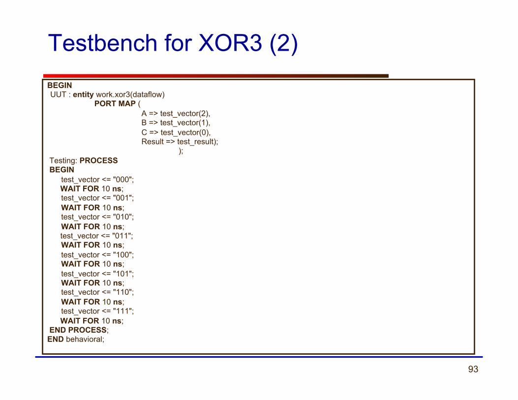
Testbench for XOR3 (2) BEGIN UUT : entity work.xor3(dataflow) PORT MAP ( A => test_vector(2), B => test_vector(1), C => test_vector(0), Result => test_result); ); Testing: PROCESS BEGIN test_vector <= "000"; WAIT FOR 10 ns; test_vector <= "001"; WAIT FOR 10 ns; test_vector <= "010"; WAIT FOR 10 ns; test_vector <= "011"; WAIT FOR 10 ns; test_vector <= "100"; WAIT FOR 10 ns; test_vector <= "101"; WAIT FOR 10 ns; test_vector <= "110"; WAIT FOR 10 ns; test_vector <= "111"; WAIT FOR 10 ns; END PROCESS; END behavioral;
94 ECE 448 – FPGA and ASIC Design with VHDL
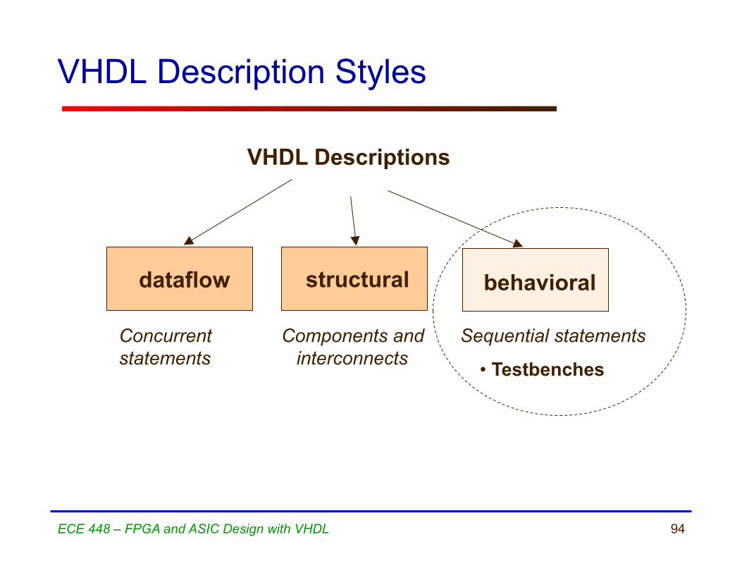
VHDL Description Styles
Components and interconnects
structural
VHDL Descriptions
dataflow
Concurrent statements
behavioral
• Testbenches
Sequential statements
95 ECE 448 – FPGA and ASIC Design with VHDL
Process without Sensitivity List and its use in Testbenches

96
• A process can be given a unique name using an optional LABEL
• This is followed by the keyword PROCESS
• The keyword BEGIN is used to indicate the start of the process
• All statements within the process are executed SEQUENTIALLY. Hence, order of statements is important.
• A process must end with the keywords END PROCESS.
Testing: PROCESS BEGIN
test_vector<=“00”; WAIT FOR 10 ns; test_vector<=“01”; WAIT FOR 10 ns; test_vector<=“10”; WAIT FOR 10 ns; test_vector<=“11”; WAIT FOR 10 ns;
END PROCESS;
• A process is a sequence of instructions referred to as sequential statements.
What is a PROCESS?
The keyword PROCESS
97
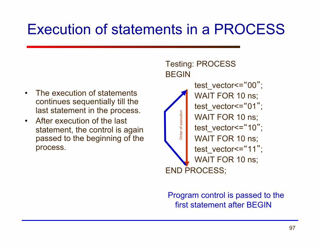
Execution of statements in a PROCESS
• The execution of statements continues sequentially till the last statement in the process.
• After execution of the last statement, the control is again passed to the beginning of the process.
Testing: PROCESS BEGIN
test_vector<=“00”; WAIT FOR 10 ns; test_vector<=“01”; WAIT FOR 10 ns; test_vector<=“10”; WAIT FOR 10 ns; test_vector<=“11”; WAIT FOR 10 ns;
END PROCESS;
Ord
er o
f exe
cutio
n
Program control is passed to the first statement after BEGIN
98
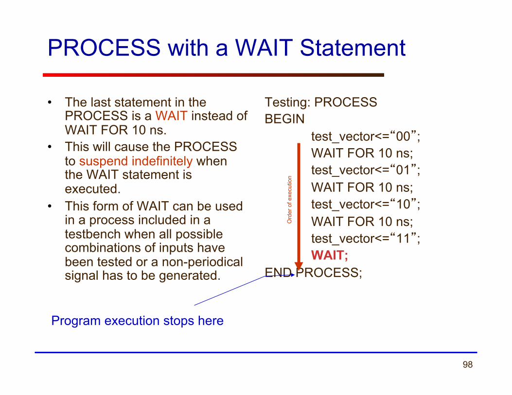
PROCESS with a WAIT Statement
• The last statement in the PROCESS is a WAIT instead of WAIT FOR 10 ns.
• This will cause the PROCESS to suspend indefinitely when the WAIT statement is executed.
• This form of WAIT can be used in a process included in a testbench when all possible combinations of inputs have been tested or a non-periodical signal has to be generated.
Testing: PROCESS BEGIN
test_vector<=“00”; WAIT FOR 10 ns; test_vector<=“01”; WAIT FOR 10 ns; test_vector<=“10”; WAIT FOR 10 ns; test_vector<=“11”; WAIT;
END PROCESS;
Program execution stops here
Ord
er o
f exe
cutio
n
99
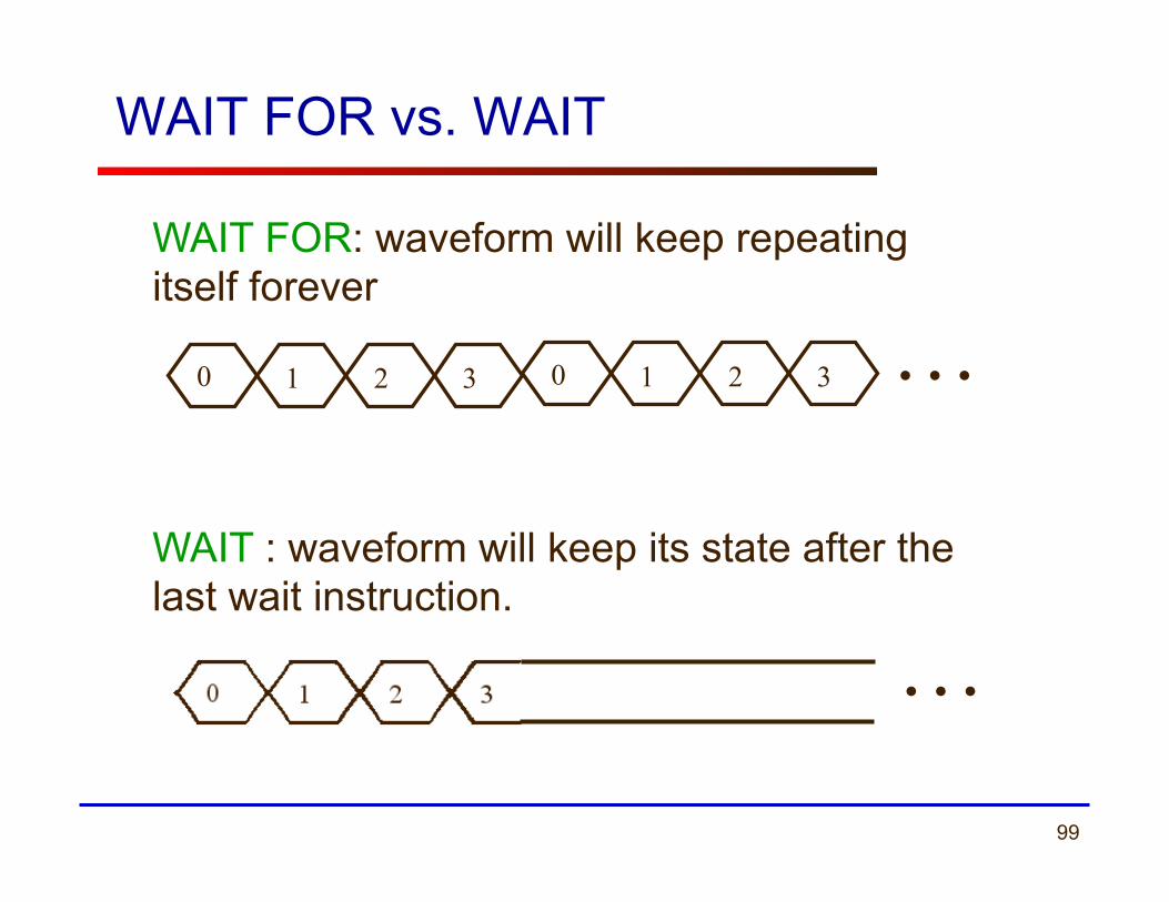
WAIT FOR vs. WAIT
WAIT FOR: waveform will keep repeating itself forever
WAIT : waveform will keep its state after the last wait instruction.
0 1 2 3
…
0 1 2 3 …
100 ECE 448 – FPGA and ASIC Design with VHDL
Specifying time in VHDL
101
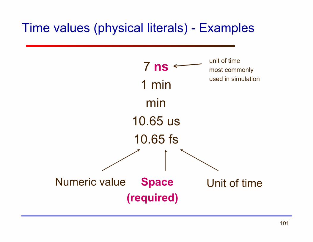
Time values (physical literals) - Examples
7 ns 1 min min
10.65 us 10.65 fs
Unit of time Space (required)
Numeric value
unit of time most commonly used in simulation
102
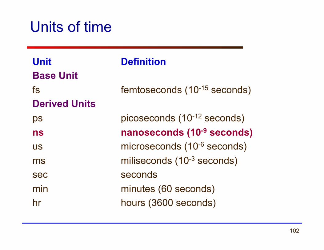
Units of time
Unit Definition Base Unit fs femtoseconds (10-15 seconds) Derived Units ps picoseconds (10-12 seconds) ns nanoseconds (10-9 seconds) us microseconds (10-6 seconds) ms miliseconds (10-3 seconds) sec seconds min minutes (60 seconds) hr hours (3600 seconds)
103 ECE 448 – FPGA and ASIC Design with VHDL
Simple Testbenches

104
Generating selected values of one input
SIGNAL test_vector : STD_LOGIC_VECTOR(2 downto 0); BEGIN .......
testing: PROCESS BEGIN
test_vector <= "000"; WAIT FOR 10 ns; test_vector <= "001"; WAIT FOR 10 ns; test_vector <= "010"; WAIT FOR 10 ns;
test_vector <= "011"; WAIT FOR 10 ns; test_vector <= "100"; WAIT FOR 10 ns;
END PROCESS; ........ END behavioral;
105
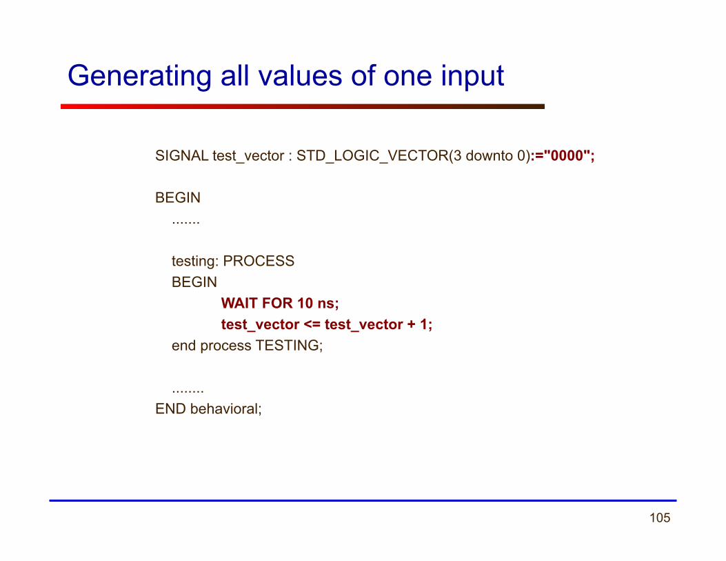
Generating all values of one input
SIGNAL test_vector : STD_LOGIC_VECTOR(3 downto 0):="0000"; BEGIN .......
testing: PROCESS BEGIN WAIT FOR 10 ns; test_vector <= test_vector + 1; end process TESTING;
........ END behavioral;
106
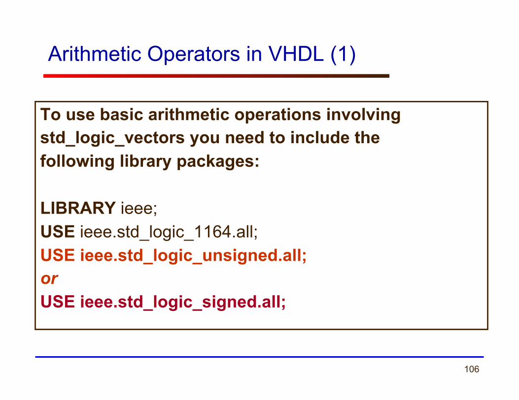
Arithmetic Operators in VHDL (1)
To use basic arithmetic operations involving std_logic_vectors you need to include the following library packages: LIBRARY ieee; USE ieee.std_logic_1164.all; USE ieee.std_logic_unsigned.all; or USE ieee.std_logic_signed.all;
107
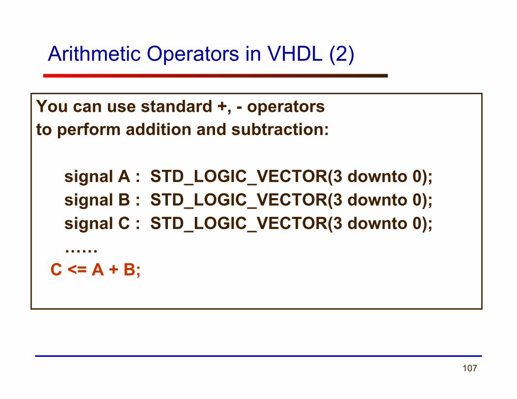
Arithmetic Operators in VHDL (2)
You can use standard +, - operators to perform addition and subtraction:
signal A : STD_LOGIC_VECTOR(3 downto 0); signal B : STD_LOGIC_VECTOR(3 downto 0); signal C : STD_LOGIC_VECTOR(3 downto 0);
…… C <= A + B;
108
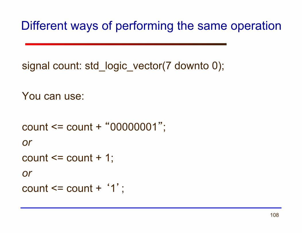
Different ways of performing the same operation
signal count: std_logic_vector(7 downto 0); You can use: count <= count + “00000001”; or count <= count + 1; or count <= count + ‘1’;
109
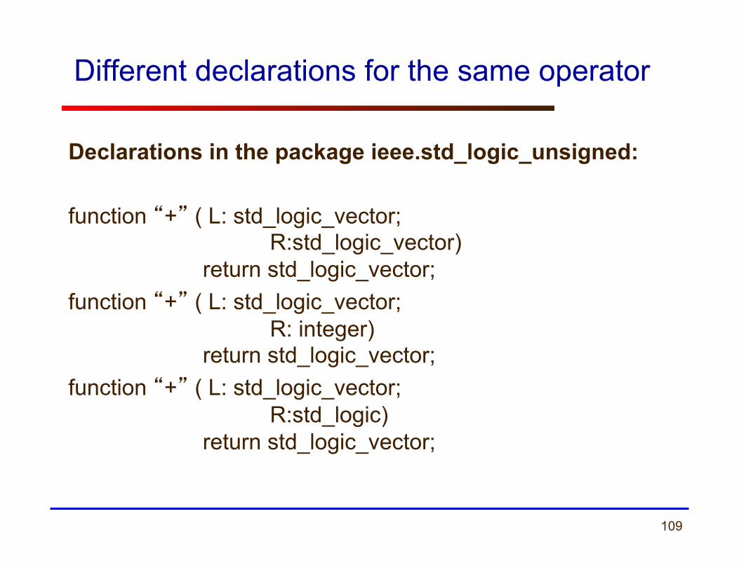
Different declarations for the same operator
Declarations in the package ieee.std_logic_unsigned: function “+” ( L: std_logic_vector;
R:std_logic_vector) return std_logic_vector;
function “+” ( L: std_logic_vector; R: integer) return std_logic_vector;
function “+” ( L: std_logic_vector; R:std_logic) return std_logic_vector;
110
Operator overloading
• Operator overloading allows different argument types for a given operation (function)
• The VHDL tools resolve which of these functions to select based on the types of the inputs
• This selection is transparent to the user as long as the function has been defined for the given argument types.
111
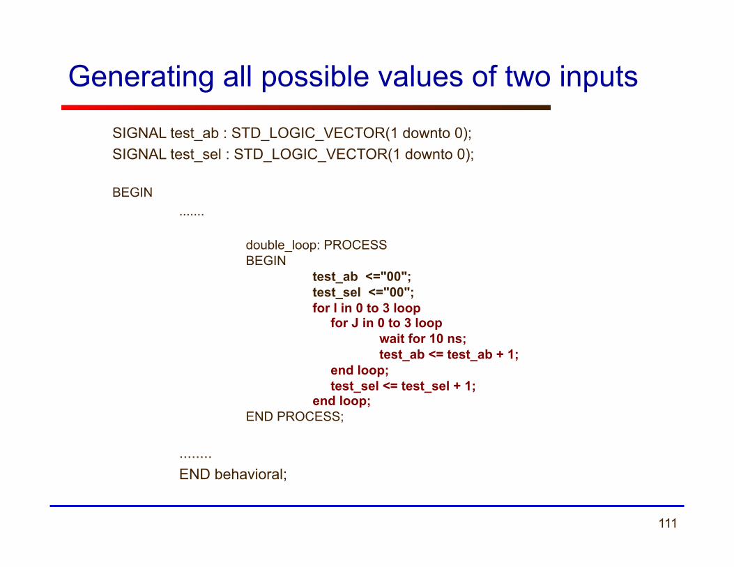
SIGNAL test_ab : STD_LOGIC_VECTOR(1 downto 0); SIGNAL test_sel : STD_LOGIC_VECTOR(1 downto 0); BEGIN .......
double_loop: PROCESS BEGIN test_ab <="00"; test_sel <="00"; for I in 0 to 3 loop for J in 0 to 3 loop wait for 10 ns; test_ab <= test_ab + 1; end loop; test_sel <= test_sel + 1; end loop; END PROCESS;
........
END behavioral;
Generating all possible values of two inputs
112
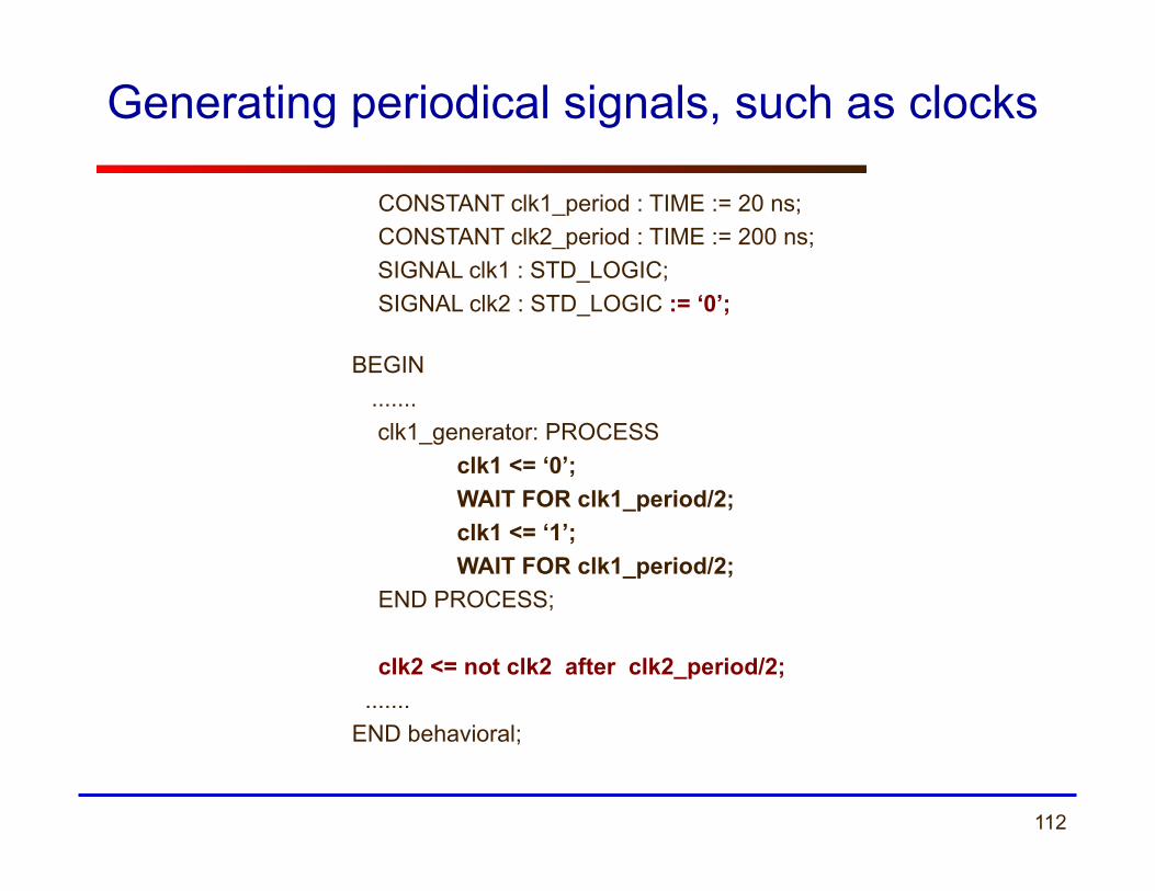
Generating periodical signals, such as clocks
CONSTANT clk1_period : TIME := 20 ns; CONSTANT clk2_period : TIME := 200 ns;
SIGNAL clk1 : STD_LOGIC; SIGNAL clk2 : STD_LOGIC := ‘0’;
BEGIN ....... clk1_generator: PROCESS clk1 <= ‘0’;
WAIT FOR clk1_period/2; clk1 <= ‘1’;
WAIT FOR clk1_period/2; END PROCESS;
clk2 <= not clk2 after clk2_period/2;
....... END behavioral;
113
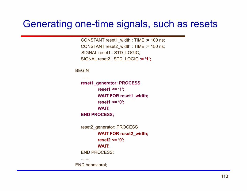
Generating one-time signals, such as resets CONSTANT reset1_width : TIME := 100 ns; CONSTANT reset2_width : TIME := 150 ns;
SIGNAL reset1 : STD_LOGIC; SIGNAL reset2 : STD_LOGIC := ‘1’;
BEGIN ....... reset1_generator: PROCESS reset1 <= ‘1’;
WAIT FOR reset1_width; reset1 <= ‘0’;
WAIT; END PROCESS;
reset2_generator: PROCESS
WAIT FOR reset2_width; reset2 <= ‘0’;
WAIT; END PROCESS;
....... END behavioral;
114
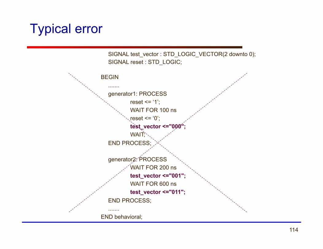
Typical error
SIGNAL test_vector : STD_LOGIC_VECTOR(2 downto 0); SIGNAL reset : STD_LOGIC;
BEGIN ....... generator1: PROCESS reset <= ‘1’;
WAIT FOR 100 ns reset <= ‘0’; test_vector <="000";
WAIT; END PROCESS;
generator2: PROCESS
WAIT FOR 200 ns test_vector <="001"; WAIT FOR 600 ns test_vector <="011"; END PROCESS; .......
END behavioral;