Embed Size (px)
Citation preview

ECE201 Lect-23 1
Transient PSpice Analysis (7.4)
Dr. Holbert
April 26, 2006
ECE201 Lect-23 2
Typical Transient Problems
• What is the voltage as a capacitor discharges to zero?
• What is the voltage as a capacitor charges from one voltage (often zero) to another constant voltage?
• How does the current through an inductor increase from zero to a final value?
• How does the current through an inductor decrease from an initial value to zero?
ECE201 Lect-23 3
More Typical Problems
• What are the transient and AC steady-state responses of an RC circuit to a sinusoidal source?
• What are the transient and AC steady-state responses of an RL circuit to a sinusoidal source?
ECE201 Lect-23 4
Solutions
• Changes in capacitor voltages and inductor currents from one value to another are easily solved.
• Changes in other voltages or currents in the circuit may or may not be easy to solve directly; they are all easy to solve using Laplace transforms (EEE 302).

ECE201 Lect-23 5
More Solutions
• Steady-state responses to sinusoidal sources are easy to find using AC steady-state analysis.
• Transient responses to sinusoidal sources are hard to find directly; they are easier to find using Laplace transforms.
ECE201 Lect-23 6
Example Problems:Changes from one value to another
• Computer RAM
– Refresh time
– Write time
• Stator coil on a motor
– Response to a step in current
ECE201 Lect-23 7
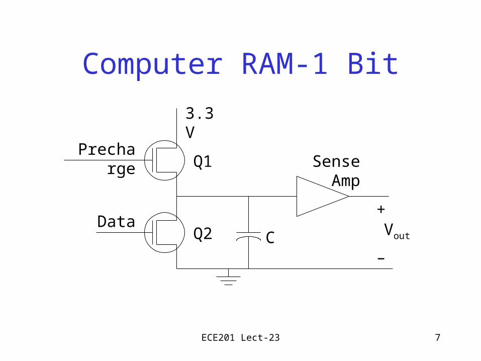
Computer RAM-1 Bit
Q1
Q2 C
Precharge
Data
3.3V
Sense Amp
+
–
Vout
ECE201 Lect-23 8
How the RAM Works
• When the Precharge line is high (> 3V) and the Data line is low (~0V), transistor Q1 is on and the capacitor charges up to 3V.
• If the Data line goes high after the capacitor is charged, then Q2 turns on and the capacitor discharges.
ECE201 Lect-23 9
RAM Discharge
• With Q1 and Q2 off, the capacitor holds a charge that represents the stored data bit.
• This charge leaks through Q2, the input of the sense amplifier, and the capacitor.
• To determine the time before a refresh is necessary, we can use a simple equivalent circuit.

ECE201 Lect-23 10
RAM Discharge Equivalent Circuit
1M 1000pF
+
–
v(t)
The 1M resistor models the parallel combination of the off resistance of Q2, the input resistance of the sense amplifier, and the leakage resistance of the capacitor.
ECE201 Lect-23 11
What is the time constant for this circuit?
ECE201 Lect-23 12
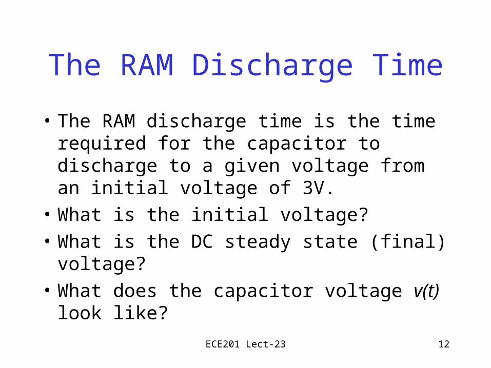
The RAM Discharge Time
• The RAM discharge time is the time required for the capacitor to discharge to a given voltage from an initial voltage of 3V.
• What is the initial voltage?
• What is the DC steady state (final) voltage?
• What does the capacitor voltage v(t) look like?
ECE201 Lect-23 13
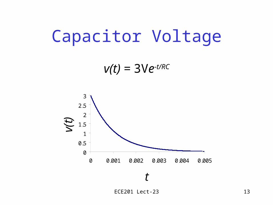
Capacitor Voltage
v(t) = 3Ve-t/RC
0
0.5
1
1.5
2
2.5
3
0 0.001 0.002 0.003 0.004 0.005
t
v(t)
ECE201 Lect-23 14
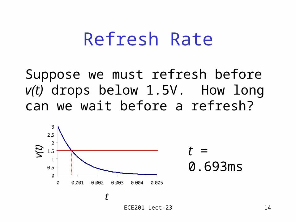
Refresh Rate
Suppose we must refresh before v(t) drops below 1.5V. How long can we wait before a refresh?
0
0.5
1
1.5
2
2.5
3
0 0.001 0.002 0.003 0.004 0.005
t
v(t) t = 0.693ms
ECE201 Lect-23 15
RAM Precharge
• With Q2 off, Q1 is turned on to charge the capacitor.
• The current to charge the capacitor comes through Q1.
• To determine the time necessary to precharge the capacitor, we use a simple equivalent circuit.
ECE201 Lect-23 16
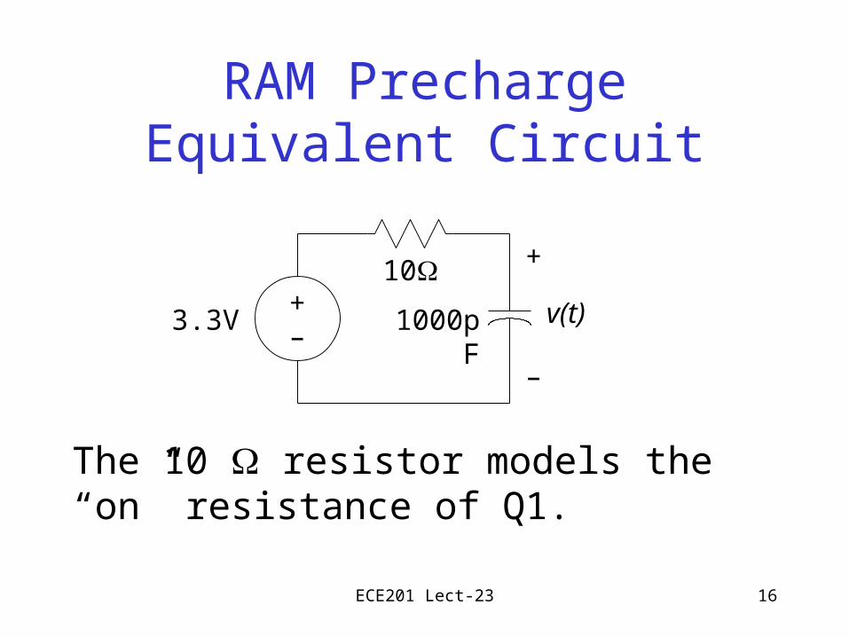
RAM Precharge Equivalent Circuit
The 10 resistor models the “on” resistance of Q1.
10
1000pF3.3V
+
–
v(t)+–

ECE201 Lect-23 17
What is the time constant for this circuit?

ECE201 Lect-23 18
The RAM Precharge Time
• The RAM precharge time is the time required for the capacitor to charge to a voltage of 3V from an initial voltage of 0V.
• What is the initial voltage?
• What is the DC steady state (final) voltage?
• What does the capacitor voltage v(t) look like?
ECE201 Lect-23 19
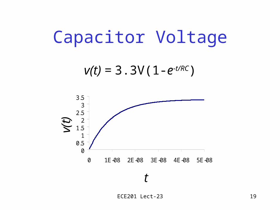
Capacitor Voltage
v(t) = 3.3V(1-e-t/RC)
00.51
1.52
2.53
3.5
0 1E-08 2E-08 3E-08 4E-08 5E-08
t
v(t)
ECE201 Lect-23 20
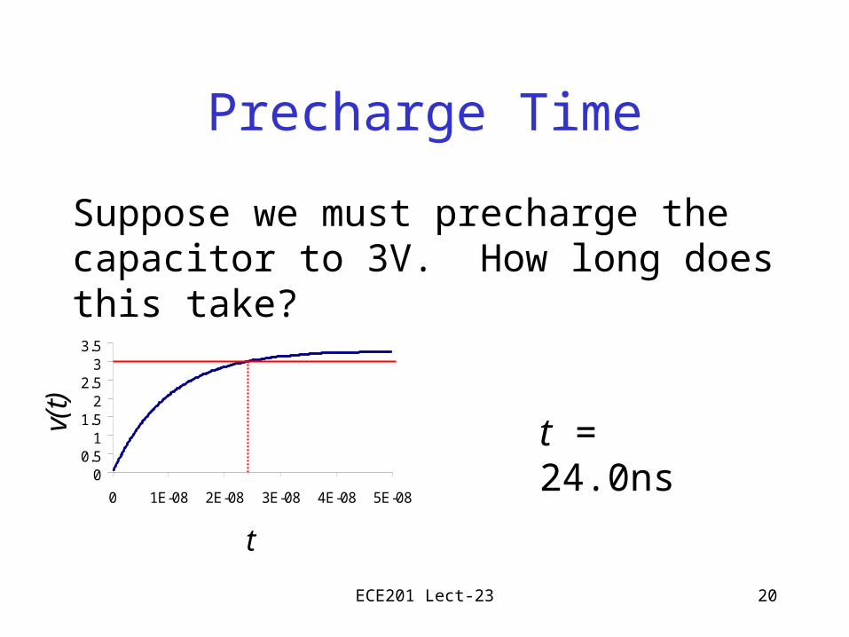
Precharge Time
Suppose we must precharge the capacitor to 3V. How long does this take?
t = 24.0ns0
0.51
1.52
2.53
3.5
0 1E-08 2E-08 3E-08 4E-08 5E-08
t
v(t)
ECE201 Lect-23 21
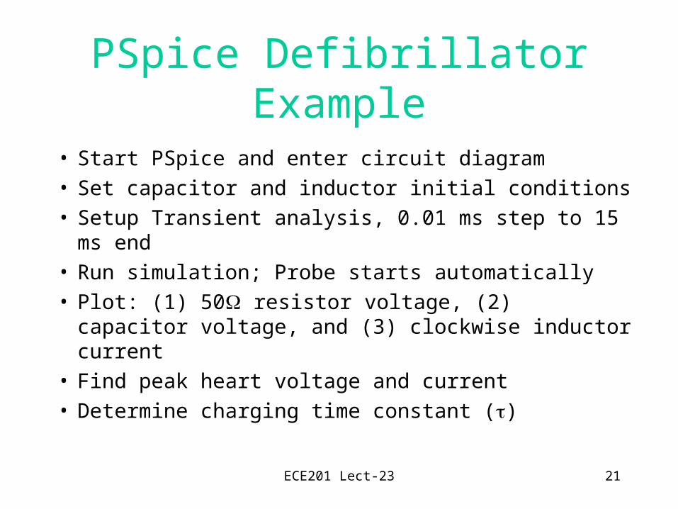
PSpice Defibrillator Example
• Start PSpice and enter circuit diagram• Set capacitor and inductor initial conditions• Setup Transient analysis, 0.01 ms step to 15 ms end• Run simulation; Probe starts automatically• Plot: (1) 50 resistor voltage, (2) capacitor voltage,
and (3) clockwise inductor current• Find peak heart voltage and current• Determine charging time constant ()
ECE201 Lect-23 22
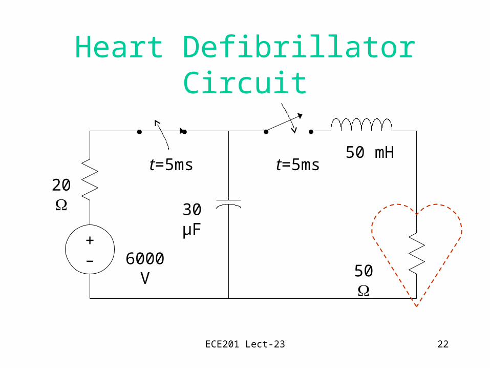
Heart Defibrillator Circuit
+–
20
50
30 µF
6000 V
50 mHt=5ms t=5ms

![121] 3-30 01/. ECE201 HW#5 Solutions 181 124 1/2 …smphilli/ece201/hw5soln.pdf121] 3-30 01/. ECE201 HW#5 Solutions 181 124 1/2 —V 2 VI , Vo-V, X - O 1.33 V 2 Q —Sowyce Sty](https://img.pdfslide.us/doc/110x75/5f0526187e708231d411835f/121-3-30-01-ece201-hw5-solutions-181-124-12-smphilliece201hw5solnpdf-121.jpg)