Embed Size (px)
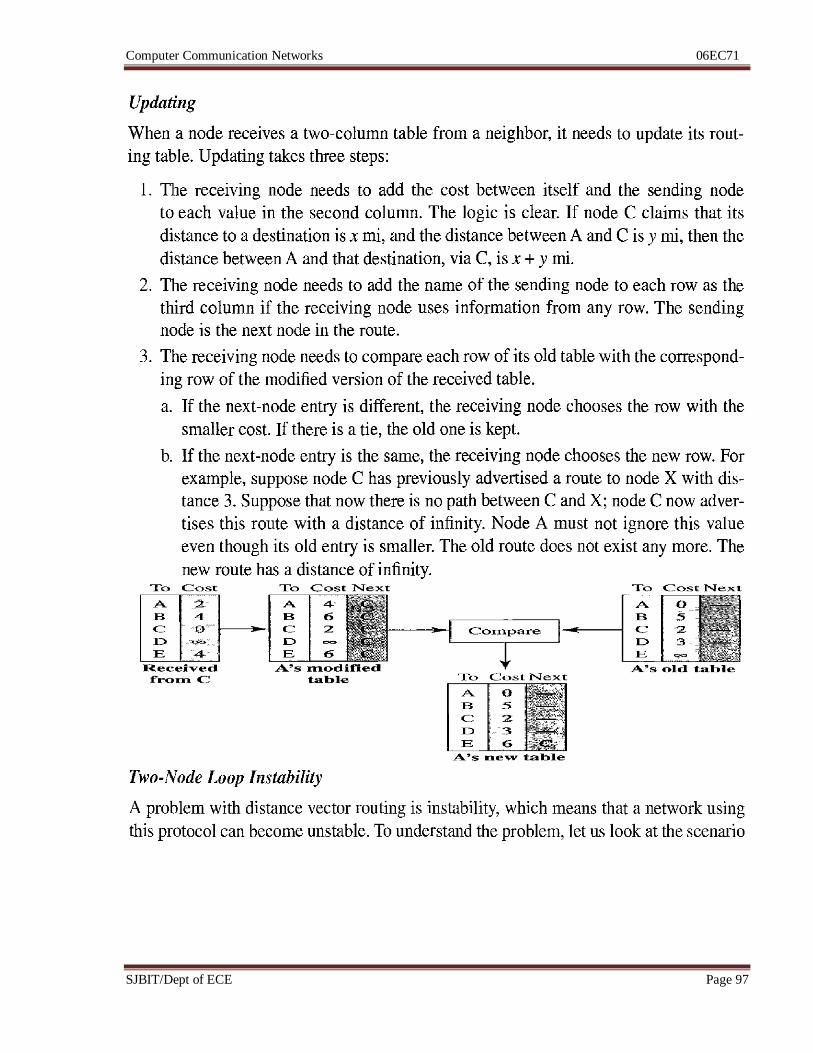
DESCRIPTION
COMPUTER COMMUNICATIONÂ_NETWORK [06EC71]-NOTES
Citation preview
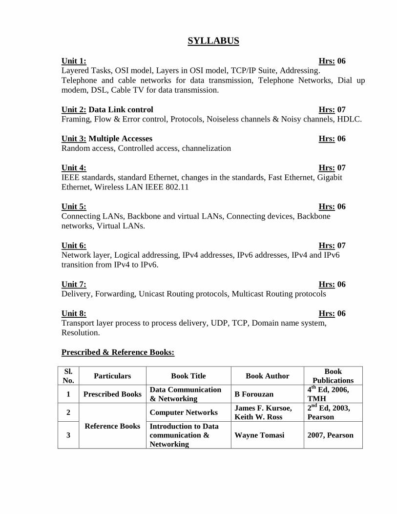
SYLLABUS
Unit 1: Hrs: 06
Layered Tasks, OSI model, Layers in OSI model, TCP/IP Suite, Addressing.
Telephone and cable networks for data transmission, Telephone Networks, Dial up
modem, DSL, Cable TV for data transmission.
Unit 2: Data Link control Hrs: 07 Framing, Flow & Error control, Protocols, Noiseless channels & Noisy channels, HDLC.
Unit 3: Multiple Accesses Hrs: 06
Random access, Controlled access, channelization
Unit 4: Hrs: 07
IEEE standards, standard Ethernet, changes in the standards, Fast Ethernet, Gigabit
Ethernet, Wireless LAN IEEE 802.11
Unit 5: Hrs: 06
Connecting LANs, Backbone and virtual LANs, Connecting devices, Backbone
networks, Virtual LANs.
Unit 6: Hrs: 07
Network layer, Logical addressing, IPv4 addresses, IPv6 addresses, IPv4 and IPv6
transition from IPv4 to IPv6.
Unit 7: Hrs: 06
Delivery, Forwarding, Unicast Routing protocols, Multicast Routing protocols
Unit 8: Hrs: 06
Transport layer process to process delivery, UDP, TCP, Domain name system,
Resolution.
Prescribed & Reference Books:
Sl.
No. Particulars Book Title Book Author
Book
Publications
1 Prescribed Books Data Communication
& Networking B Forouzan
4th
Ed, 2006,
TMH
2
Reference Books
Computer Networks James F. Kursoe,
Keith W. Ross
2nd
Ed, 2003,
Pearson
3
Introduction to Data
communication &
Networking
Wayne Tomasi 2007, Pearson
Computer Communication Networks 06EC71
SJBIT/Dept of ECE Page 1
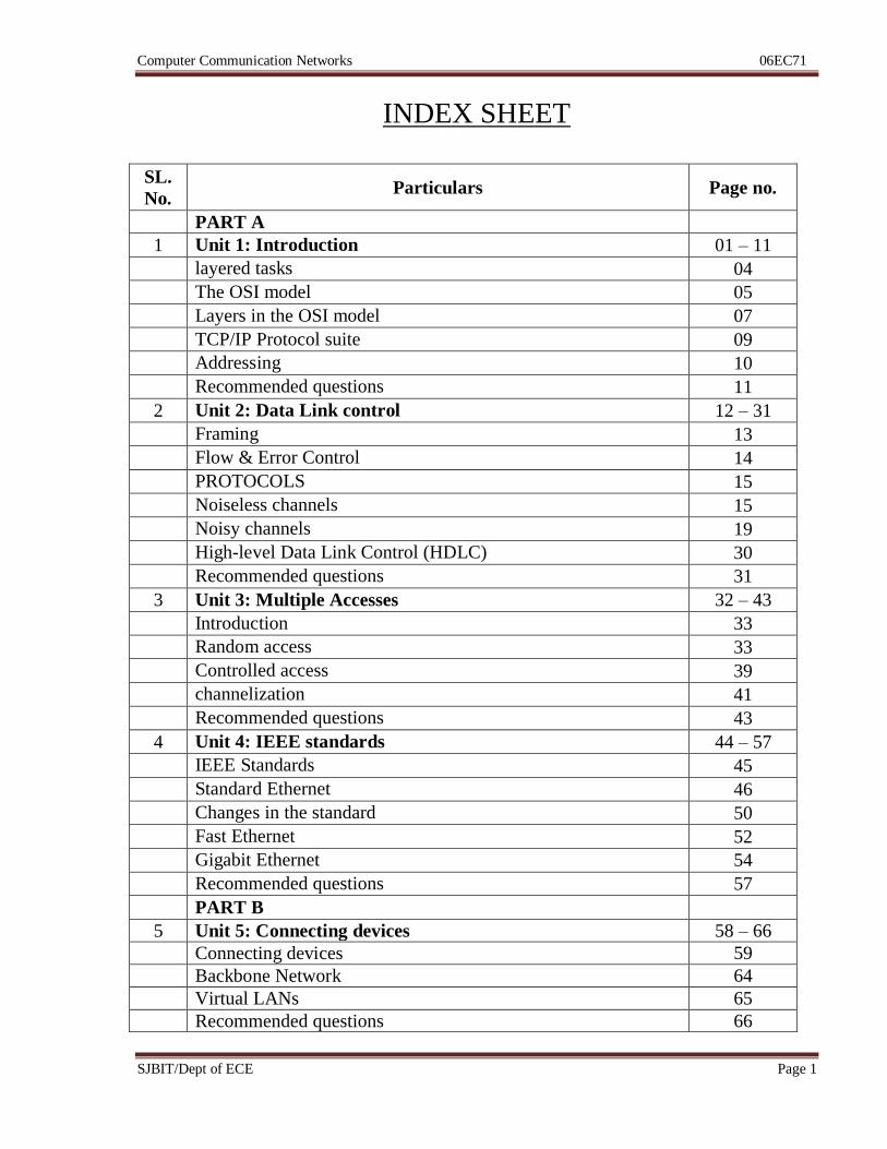
INDEX SHEET
SL.
No. Particulars Page no.
PART A
1 Unit 1: Introduction 01 – 11
layered tasks 04
The OSI model 05
Layers in the OSI model 07
TCP/IP Protocol suite 09
Addressing 10
Recommended questions 11
2 Unit 2: Data Link control 12 – 31
Framing 13
Flow & Error Control 14
PROTOCOLS 15
Noiseless channels 15
Noisy channels 19
High-level Data Link Control (HDLC) 30
Recommended questions 31
3 Unit 3: Multiple Accesses 32 – 43
Introduction 33
Random access 33
Controlled access 39
channelization 41
Recommended questions 43
4 Unit 4: IEEE standards 44 – 57
IEEE Standards 45
Standard Ethernet 46
Changes in the standard 50
Fast Ethernet 52
Gigabit Ethernet 54
Recommended questions 57
PART B
5 Unit 5: Connecting devices 58 – 66
Connecting devices 59
Backbone Network 64
Virtual LANs 65
Recommended questions 66
Computer Communication Networks 06EC71
SJBIT/Dept of ECE Page 2
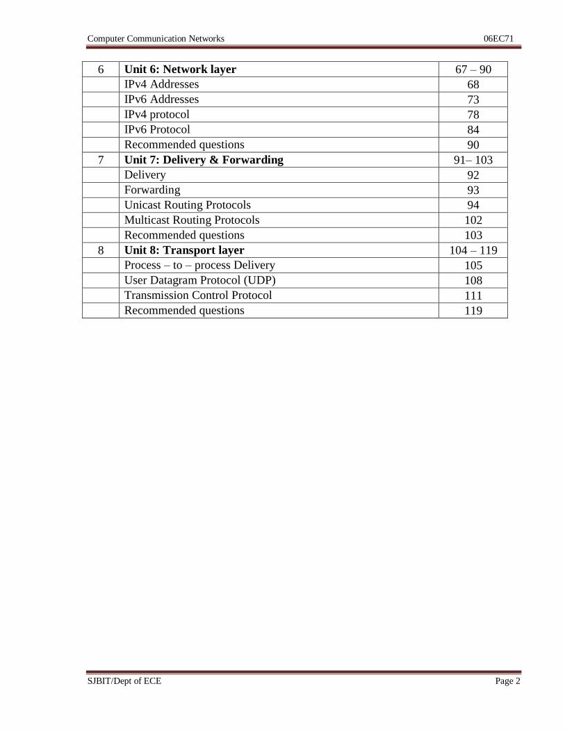
6 Unit 6: Network layer 67 – 90
IPv4 Addresses 68
IPv6 Addresses 73
IPv4 protocol 78
IPv6 Protocol 84
Recommended questions 90
7 Unit 7: Delivery & Forwarding 91– 103
Delivery 92
Forwarding 93
Unicast Routing Protocols 94
Multicast Routing Protocols 102
Recommended questions 103
8 Unit 8: Transport layer 104 – 119
Process – to – process Delivery 105
User Datagram Protocol (UDP) 108
Transmission Control Protocol 111
Recommended questions 119
Computer Communication Networks 06EC71
SJBIT/Dept of ECE Page 3
PART A
Unit 1: Network Architecture Hrs: 06
Syllabus:
Section 1: Layered Tasks, OSI model, Layers in OSI model, TCP/IP Suite, Addressing
Section 2: Telephone and cable networks for data transmission, Telephone Networks,
Dial up modem, DSL, Cable TV for data transmission.
Recommended readings:
Text Book: Data Communication & Networking, B Forouzan, 4e, TMH
Sec 1: Chapter 2 – page 27 to 50
Sec 2: Chapter 9 – page 241 to 260
Computer Communication Networks 06EC71
SJBIT/Dept of ECE Page 4
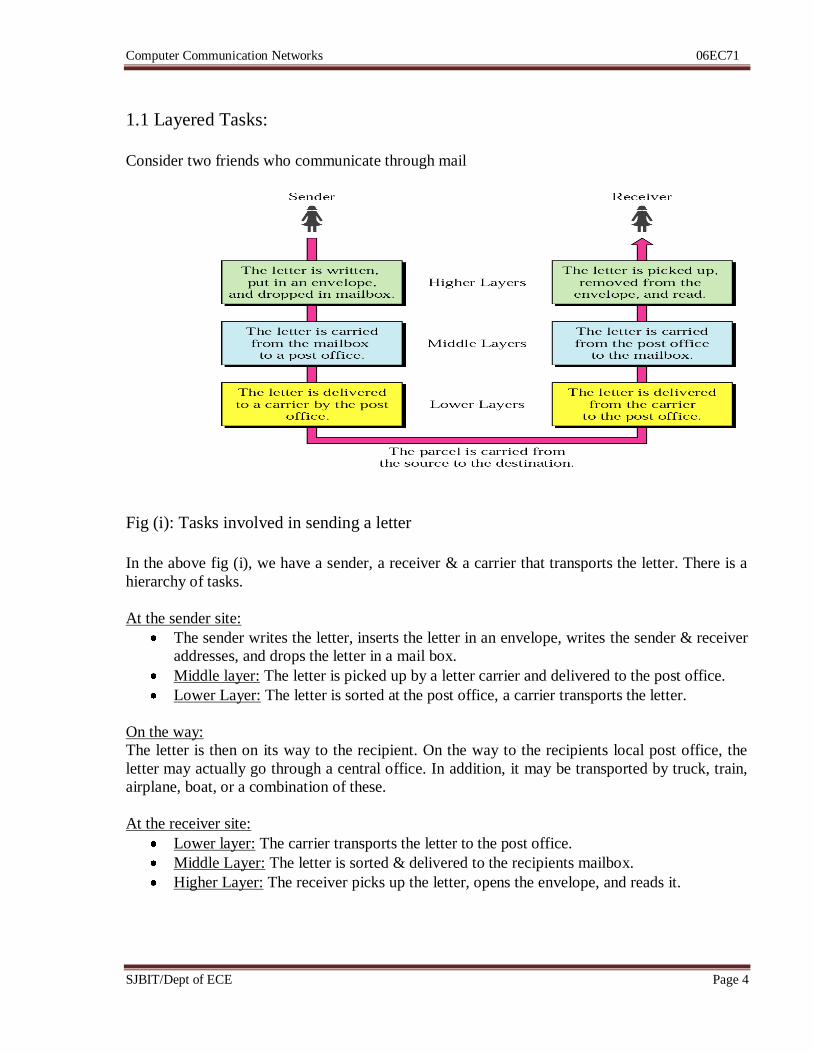
1.1 Layered Tasks:
Consider two friends who communicate through mail
Fig (i): Tasks involved in sending a letter
In the above fig (i), we have a sender, a receiver & a carrier that transports the letter. There is a
hierarchy of tasks.
At the sender site:
The sender writes the letter, inserts the letter in an envelope, writes the sender & receiver
addresses, and drops the letter in a mail box.
Middle layer: The letter is picked up by a letter carrier and delivered to the post office.
Lower Layer: The letter is sorted at the post office, a carrier transports the letter.
On the way:
The letter is then on its way to the recipient. On the way to the recipients local post office, the
letter may actually go through a central office. In addition, it may be transported by truck, train,
airplane, boat, or a combination of these.
At the receiver site:
Lower layer: The carrier transports the letter to the post office.
Middle Layer: The letter is sorted & delivered to the recipients mailbox.
Higher Layer: The receiver picks up the letter, opens the envelope, and reads it.
Computer Communication Networks 06EC71
SJBIT/Dept of ECE Page 5
Hierarchy:
The task of transporting the letter between the sender and the receiver is done by the carrier. The
tasks must be done in the order given in the hierarchy. At the sender site, the letter must be
written and dropped in the mailbox before being picked up by the letter carrier and delivered to
the post office. At the receiver site, the letter must be dropped in the recipient mailbox before
being picked up & read by the recipient. Services:
Each layer at the sending site uses the services of the layer immediately below it. The sender at
the higher layer uses the services of the middle layer. The middle layer uses the services of the
lower layer. The lower layer uses the services of the carrier.
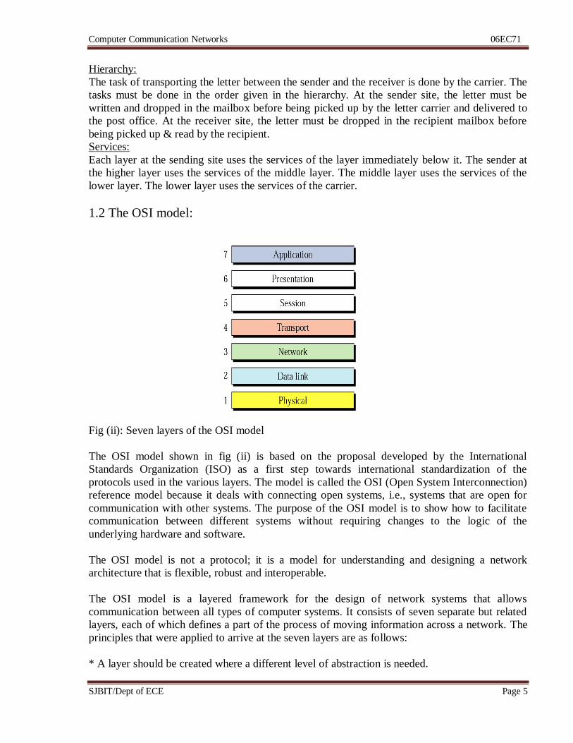
1.2 The OSI model:
Fig (ii): Seven layers of the OSI model
The OSI model shown in fig (ii) is based on the proposal developed by the International
Standards Organization (ISO) as a first step towards international standardization of the
protocols used in the various layers. The model is called the OSI (Open System Interconnection)
reference model because it deals with connecting open systems, i.e., systems that are open for
communication with other systems. The purpose of the OSI model is to show how to facilitate
communication between different systems without requiring changes to the logic of the
underlying hardware and software.
The OSI model is not a protocol; it is a model for understanding and designing a network
architecture that is flexible, robust and interoperable.
The OSI model is a layered framework for the design of network systems that allows
communication between all types of computer systems. It consists of seven separate but related
layers, each of which defines a part of the process of moving information across a network. The
principles that were applied to arrive at the seven layers are as follows:
* A layer should be created where a different level of abstraction is needed.
Computer Communication Networks 06EC71
SJBIT/Dept of ECE Page 6
* Each layer should perform a well-defined function.
* The function of each layer should be chosen with an eye toward defining internationally
standardized protocols.
* The layer boundaries should be chosen to minimize the information flow across the interfaces.
* The number of layers should be large enough that distinct functions need not be thrown
together in the same layer out of necessity and small enough that the architecture does not
become unwieldy.
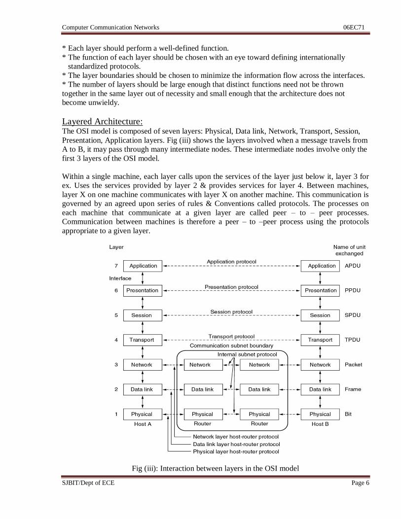
Layered Architecture: The OSI model is composed of seven layers: Physical, Data link, Network, Transport, Session,
Presentation, Application layers. Fig (iii) shows the layers involved when a message travels from
A to B, it may pass through many intermediate nodes. These intermediate nodes involve only the
first 3 layers of the OSI model.
Within a single machine, each layer calls upon the services of the layer just below it, layer 3 for
ex. Uses the services provided by layer 2 & provides services for layer 4. Between machines,
layer X on one machine communicates with layer X on another machine. This communication is
governed by an agreed upon series of rules & Conventions called protocols. The processes on
each machine that communicate at a given layer are called peer – to – peer processes.
Communication between machines is therefore a peer – to –peer process using the protocols
appropriate to a given layer.
Fig (iii): Interaction between layers in the OSI model
Computer Communication Networks 06EC71
SJBIT/Dept of ECE Page 7
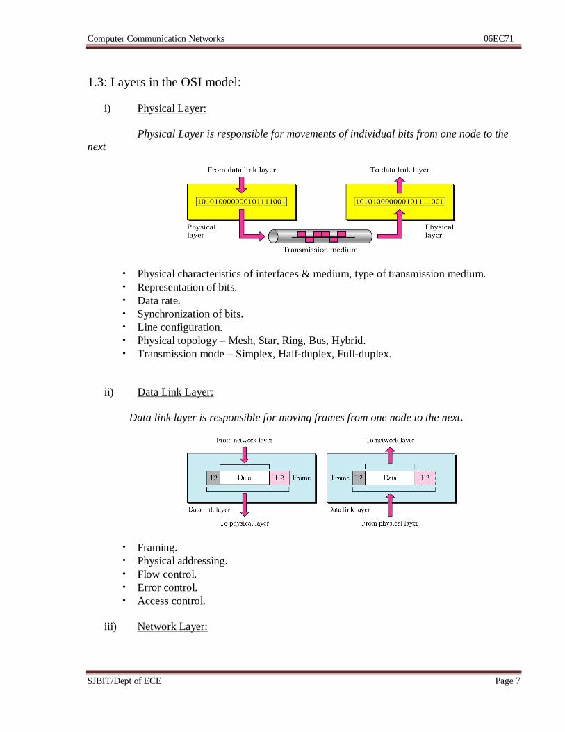
1.3: Layers in the OSI model:
i) Physical Layer:
Physical Layer is responsible for movements of individual bits from one node to the
next
• Physical characteristics of interfaces & medium, type of transmission medium.
• Representation of bits.
• Data rate.
• Synchronization of bits.
• Line configuration.
• Physical topology – Mesh, Star, Ring, Bus, Hybrid.
• Transmission mode – Simplex, Half-duplex, Full-duplex.
ii) Data Link Layer:
Data link layer is responsible for moving frames from one node to the next.
• Framing.
• Physical addressing.
• Flow control.
• Error control.
• Access control.
iii) Network Layer:
Computer Communication Networks 06EC71
SJBIT/Dept of ECE Page 8
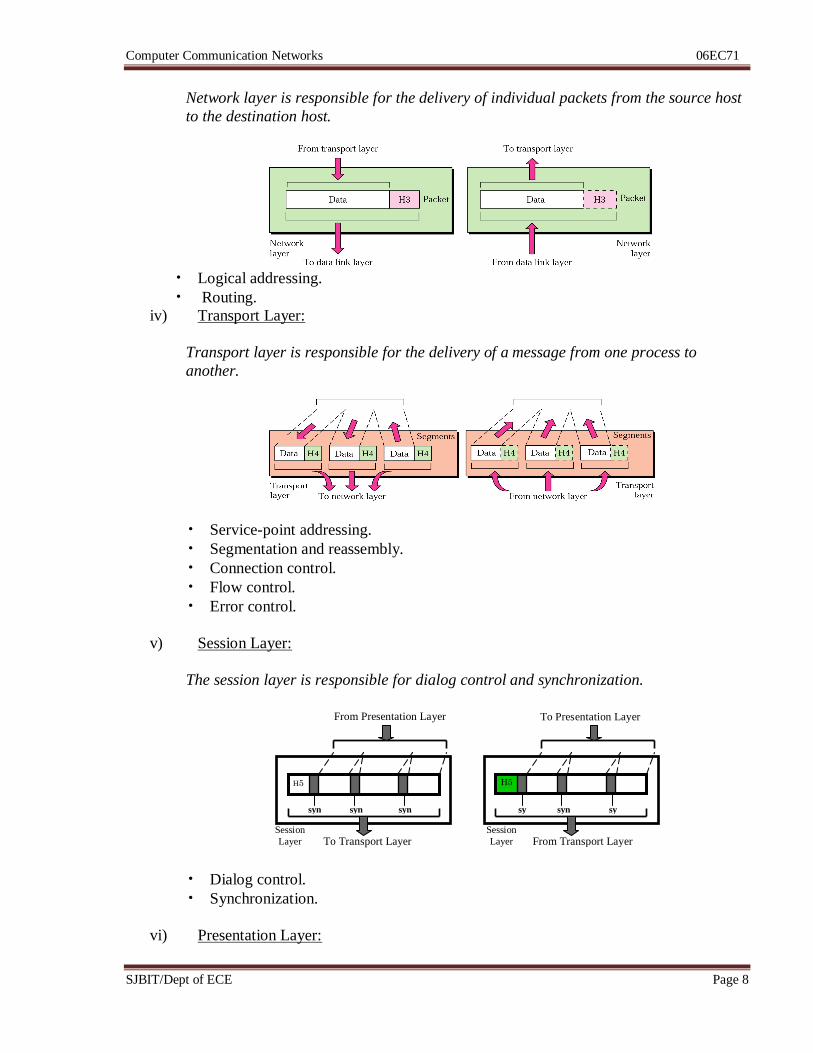
Network layer is responsible for the delivery of individual packets from the source host
to the destination host.
• Logical addressing.
• Routing.
iv) Transport Layer:
Transport layer is responsible for the delivery of a message from one process to
another.
• Service-point addressing.
• Segmentation and reassembly.
• Connection control.
• Flow control.
• Error control.
v) Session Layer:
The session layer is responsible for dialog control and synchronization.
• Dialog control.
• Synchronization.
vi) Presentation Layer:
H5
syn syn syn
H5
sy
n
syn sy
n
To Transport Layer From Transport Layer
To Presentation Layer From Presentation Layer
Session
Layer
Session
Layer
Computer Communication Networks 06EC71
SJBIT/Dept of ECE Page 9
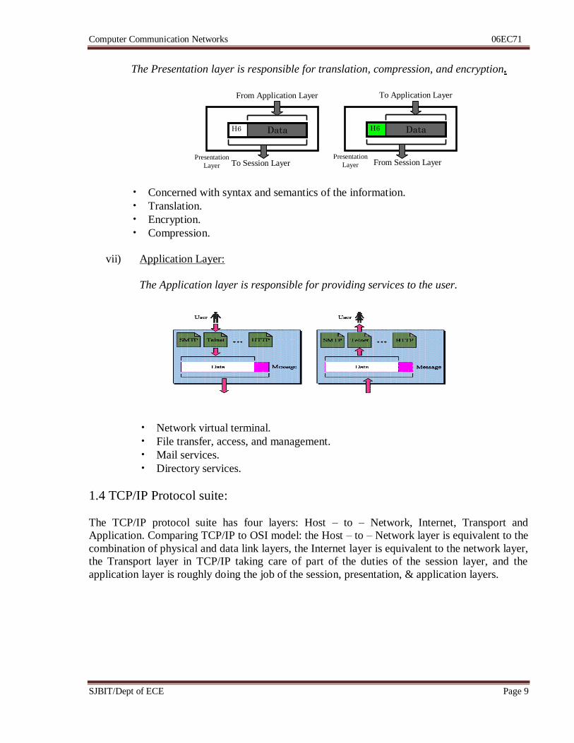
The Presentation layer is responsible for translation, compression, and encryption.
• Concerned with syntax and semantics of the information.
• Translation.
• Encryption.
• Compression.
vii) Application Layer:
The Application layer is responsible for providing services to the user.
• Network virtual terminal.
• File transfer, access, and management.
• Mail services.
• Directory services.
1.4 TCP/IP Protocol suite:
The TCP/IP protocol suite has four layers: Host – to – Network, Internet, Transport and
Application. Comparing TCP/IP to OSI model: the Host – to – Network layer is equivalent to the
combination of physical and data link layers, the Internet layer is equivalent to the network layer,
the Transport layer in TCP/IP taking care of part of the duties of the session layer, and the
application layer is roughly doing the job of the session, presentation, & application layers.
Data H6
To Session Layer
From Application Layer
Presentation
Layer
Data H6
From Session Layer
To Application Layer
Presentation
Layer
Computer Communication Networks 06EC71
SJBIT/Dept of ECE Page 10
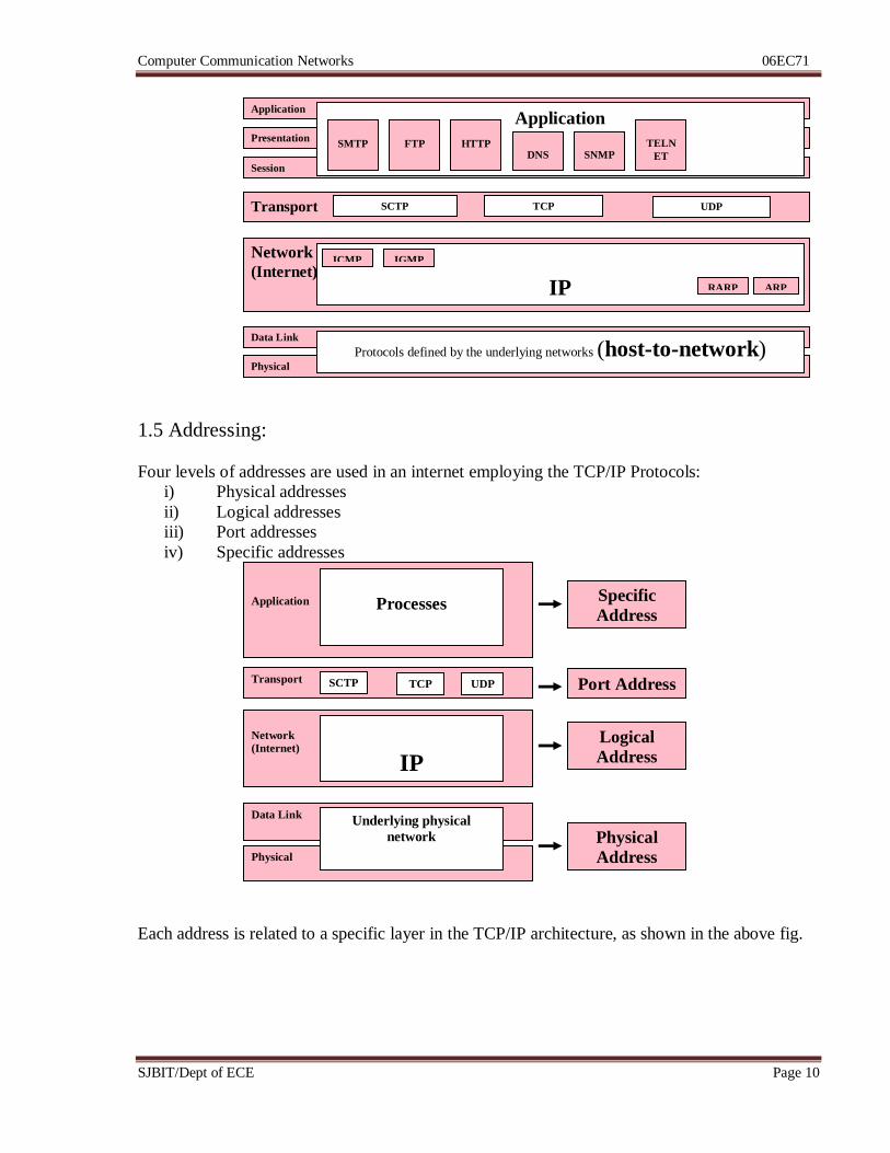
1.5 Addressing:
Four levels of addresses are used in an internet employing the TCP/IP Protocols:
i) Physical addresses
ii) Logical addresses
iii) Port addresses
iv) Specific addresses
Each address is related to a specific layer in the TCP/IP architecture, as shown in the above fig.
Session
Presentation
Application Application
Transport SCTP TCP UDP
SMTP
FTP
HTTP
DNS
SNMP
TELN
ET
Network
(Internet)
IP
ICMP IGMP
RARP ARP
Physical
Data Link
Protocols defined by the underlying networks (host-to-network)
Application
Processes
Transport SCTP TCP UDP
Network
(Internet)
IP
Physical
Data Link Underlying physical
network Physical
Address
Logical
Address
Port Address
Specific
Address
Computer Communication Networks 06EC71
SJBIT/Dept of ECE Page 11
Recommended questions:
1) List at-least 5 main responsibilities of Data link layer & Transport layer of OSI
reference model.
2) What is layered architecture? Explain the interaction between the layers using
a suitable diagram. 3) What are the responsibilities of the network layer in the internet model?
4) Name some services provided by the application layer in the internet model.
5) What is the difference between a port address, a logical address and a physical layer address?
6) What is a peer-to-peer process?
7) What are the concerns of the physical layer in the internet model?
8) What are the headers and trailers, and how do they get added and removed?
Computer Communication Networks 06EC71
SJBIT/Dept of ECE Page 12
Unit 2: Data Link control Hrs: 07
Syllabus:
Framing, Flow & Error control, Protocols, Noiseless channels & Noisy channels, HDLC.
Recommended readings:
Text Book: Data Communication & Networking, B Forouzan, 4e, TMH
Chapter 11 – page 307 to 346
Computer Communication Networks 06EC71
SJBIT/Dept of ECE Page 13
2.1 Framing:
Framing in the data link layer separates a message from one source to a destination by adding a
sender address & a destination address. The destination address defines where the packet is to
go; the sender address helps the recipient acknowledge the receipt. Although the whole message
could be packed in one frame, that is not normally done. One reason is that a frame can be very
large, making flow & error control very inefficient. When a message is carried in one very large
frame, even a single-bit error would require the retransmission of the whole message. When a
message is divided into smaller frames, a single-bit error affects only that small frame.
Frames can be of fixed or variable size.
i) Fixed-size framing:
In this there is no need for defining the boundaries of the frames, the size itself can be used as a
delimiter.
Ex: ATM wide area network which uses frames of fixed size called cells.
ii) Variable-size framing:
In this, we need a way to define the end of the frame and the beginning of the next.
Ex: LAN
Historically 2 approaches were used for variable size framing: Character-oriented & bit-oriented.
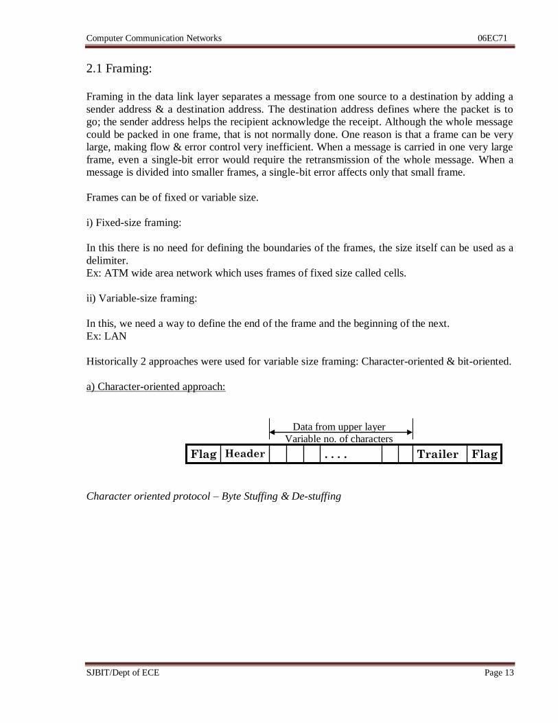
a) Character-oriented approach:
Character oriented protocol – Byte Stuffing & De-stuffing
Flag Trailer . . . . Header Flag
Data from upper layer
Variable no. of characters
Computer Communication Networks 06EC71
SJBIT/Dept of ECE Page 14
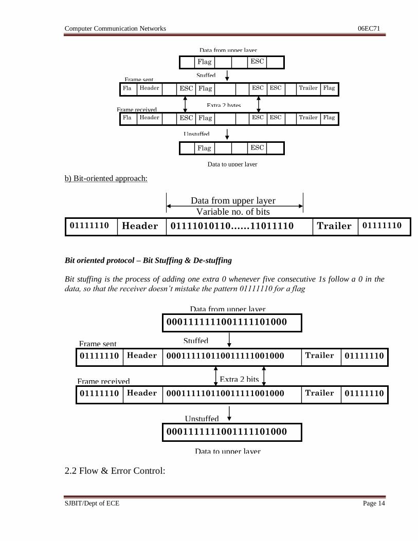
b) Bit-oriented approach:
Bit oriented protocol – Bit Stuffing & De-stuffing
Bit stuffing is the process of adding one extra 0 whenever five consecutive 1s follow a 0 in the
data, so that the receiver doesn’t mistake the pattern 01111110 for a flag
2.2 Flow & Error Control:
Data from upper layer
ESC Flag
Flag Trailer ESC ESC Flag ESC Header Fla
g
Flag Trailer ESC ESC Flag ESC Header Fla
g
ESC Flag
Data to upper layer
Unstuffed
Extra 2 bytes Frame received
Frame sent Stuffed
01111110 Trailer 01111010110……11011110 Header 01111110
Data from upper layer
Variable no. of bits
Data from upper layer
0001111111001111101000
01111110 Trailer 000111110110011111001000 Header 01111110
01111110 Trailer 000111110110011111001000 Header 01111110
0001111111001111101000
Data to upper layer
Frame sent
Frame received
Stuffed
Unstuffed
Extra 2 bits
Computer Communication Networks 06EC71
SJBIT/Dept of ECE Page 15
Flow Control:
• Any receiving device has a limited speed at which it can process incoming data and a
limited amount of memory in which to store incoming data.
• The flow of data must not be allowed to overwhelm the receiver.
• The receiver must be able to tell the sender to halt transmission until it is once again able
to receive.
• Flow control refers to a set of procedures used to restrict the amount of data that the
sender can send before waiting for acknowledgement.
Error Control: • Errors occur due to noises in the channel.
• Error control is both error detection & error correction.
• In the data link layer error control refers to methods of error detection and retransmission.
• To sender should add certain amount of redundant bits to the data, based on which the
receiver will be able to detect errors.
2.3 PROTOCOLS:
• A protocol is a set of rules that govern data communication.
• A protocol defines what, how it is communicated, and when it is communicated.
• The key elements of a protocol are syntax, semantics & timing.
• Syntax refers to the structure or format of the data, i.e., the order in which they are
presented.
• Semantics refers to the meaning of each section of bits.
• Timing refers to when data should be sent & how fast they can be sent.
• Protocols are implemented in software by using any of the common programming
languages.
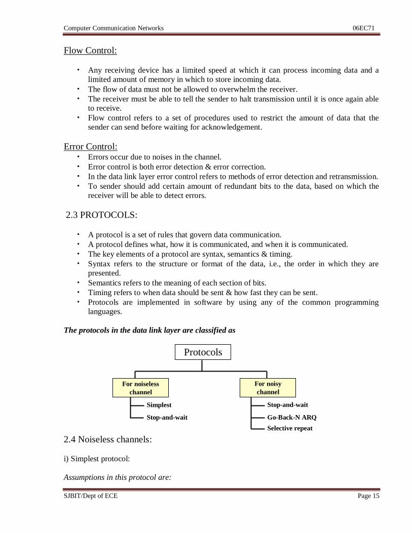
The protocols in the data link layer are classified as
2.4 Noiseless channels:
i) Simplest protocol:
Assumptions in this protocol are:
Protocols
For noiseless
channel
For noisy
channel
Simplest
Stop-and-wait
Stop-and-wait
ARQ Go-Back-N ARQ
Selective repeat
ARQ
Computer Communication Networks 06EC71
SJBIT/Dept of ECE Page 16
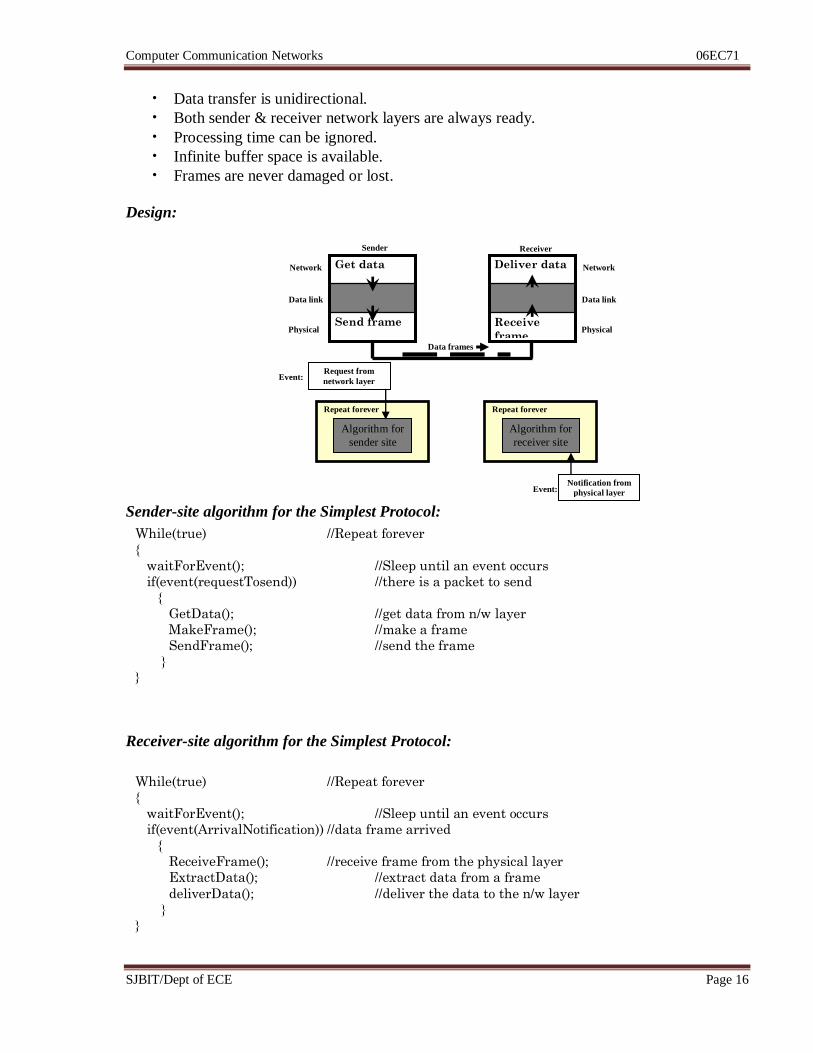
• Data transfer is unidirectional.
• Both sender & receiver network layers are always ready.
• Processing time can be ignored.
• Infinite buffer space is available.
• Frames are never damaged or lost.
Design:
Sender-site algorithm for the Simplest Protocol:
Receiver-site algorithm for the Simplest Protocol:
Send frame
Get data
Receive
frame
Deliver data
Algorithm for
sender site
Repeat forever
Algorithm for
receiver site
Repeat forever
Data frames
Network
Data link
Physical
Network
Data link
Physical
Sender Receiver
Request from
network layer
Notification from
physical layer
Event:
Event:
While(true) //Repeat forever
{
waitForEvent(); //Sleep until an event occurs
if(event(requestTosend)) //there is a packet to send
{
GetData(); //get data from n/w layer
MakeFrame(); //make a frame
SendFrame(); //send the frame
} }
While(true) //Repeat forever
{
waitForEvent(); //Sleep until an event occurs
if(event(ArrivalNotification)) //data frame arrived
{
ReceiveFrame(); //receive frame from the physical layer
ExtractData(); //extract data from a frame
deliverData(); //deliver the data to the n/w layer
}
}
Computer Communication Networks 06EC71
SJBIT/Dept of ECE Page 17
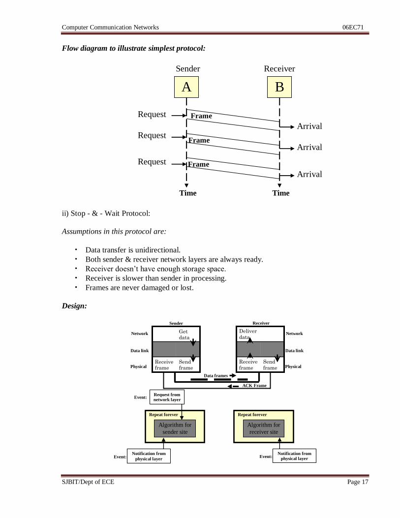
Flow diagram to illustrate simplest protocol:
ii) Stop - & - Wait Protocol:
Assumptions in this protocol are:
• Data transfer is unidirectional.
• Both sender & receiver network layers are always ready.
• Receiver doesn’t have enough storage space.
• Receiver is slower than sender in processing.
• Frames are never damaged or lost.
Design:
A B
Time Time
Request
Arrival
Arrival
Arrival
Request
Request
Frame
Frame
Frame
Sender Receiver
Algorithm for
sender site
Repeat forever
Algorithm for
receiver site
Repeat forever
Data frames
Network
Data link
Physical
Network
Data link
Physical
Sender Receiver
Request from network layer
Notification from physical layer
Event:
Event:
Send
frame
Receive
frame
Deliver
data
Send frame
Receive frame
Get data
ACK Frame
Notification from
physical layer Event:
Computer Communication Networks 06EC71
SJBIT/Dept of ECE Page 18
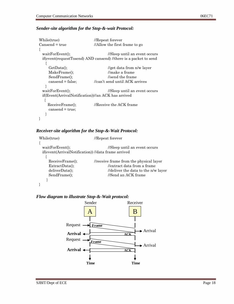
Sender-site algorithm for the Stop-&-wait Protocol:
Receiver-site algorithm for the Stop-&-Wait Protocol:
Flow diagram to illustrate Stop-&-Wait protocol:
While(true) //Repeat forever
Cansend = true //Allow the first frame to go
{
waitForEvent(); //Sleep until an event occurs
if(event(requestTosend) AND cansend) //there is a packet to send
{
GetData(); //get data from n/w layer
MakeFrame(); //make a frame
SendFrame(); //send the frame
cansend = false; //can’t send until ACK arrives
}
waitForEvent(); //Sleep until an event occurs
if(Event(ArrivalNotification)) //an ACK has arrived
{
ReceiveFrame(); //Receive the ACK frame
cansend = true;
}
}
While(true) //Repeat forever
{
waitForEvent(); //Sleep until an event occurs
if(event(ArrivalNotification)) //data frame arrived
{
ReceiveFrame(); //receive frame from the physical layer
ExtractData(); //extract data from a frame
deliverData(); //deliver the data to the n/w layer
SendFrame(); //Send an ACK frame
}
}
A B
Time Time
Request
Arrival
Arrival
Request
Frame
Frame
Sender Receiver
ACK
ACK
Arrival
Arrival
Computer Communication Networks 06EC71
SJBIT/Dept of ECE Page 19
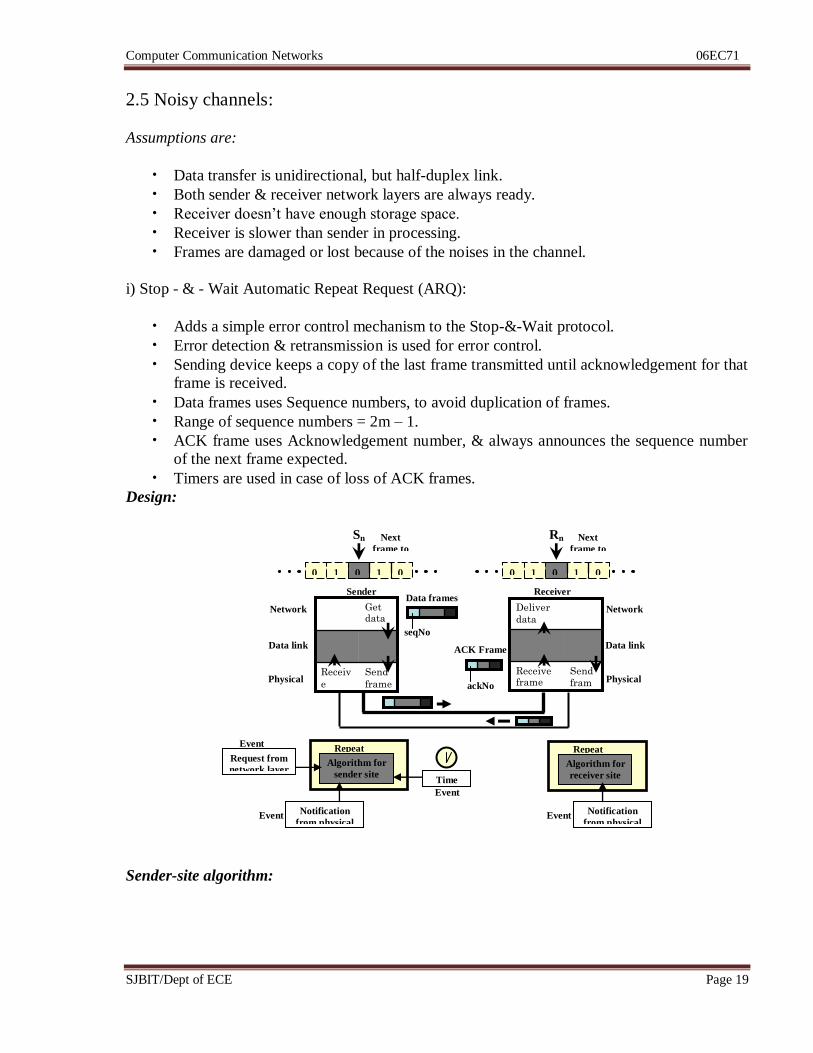
2.5 Noisy channels:
Assumptions are:
• Data transfer is unidirectional, but half-duplex link.
• Both sender & receiver network layers are always ready.
• Receiver doesn’t have enough storage space.
• Receiver is slower than sender in processing.
• Frames are damaged or lost because of the noises in the channel.
i) Stop - & - Wait Automatic Repeat Request (ARQ):
• Adds a simple error control mechanism to the Stop-&-Wait protocol.
• Error detection & retransmission is used for error control.
• Sending device keeps a copy of the last frame transmitted until acknowledgement for that
frame is received.
• Data frames uses Sequence numbers, to avoid duplication of frames.
• Range of sequence numbers = 2m – 1.
• ACK frame uses Acknowledgement number, & always announces the sequence number
of the next frame expected.
• Timers are used in case of loss of ACK frames.
Design:
Sender-site algorithm:
Algorithm for
sender site
Repeat
forever
Data frames
Network
Data link
Physical
Network
Data link
Physical
Sender Receiver
Request from
network layer
Event
:
Send
fram
e
Receive frame
Deliver
data
Send
frame
Receiv
e
frame
Get data
ACK Frame
Notification
from physical
layer
Notification
from physical
layer
Event
:
Algorithm for
receiver site
Repeat
forever
Event
:
0 1 0 1 0
Sn Next
frame to
send
0 1 0 1 0
Rn Next
frame to
receive
Time
Out Event
:
ackNo
seqNo
Computer Communication Networks 06EC71
SJBIT/Dept of ECE Page 20
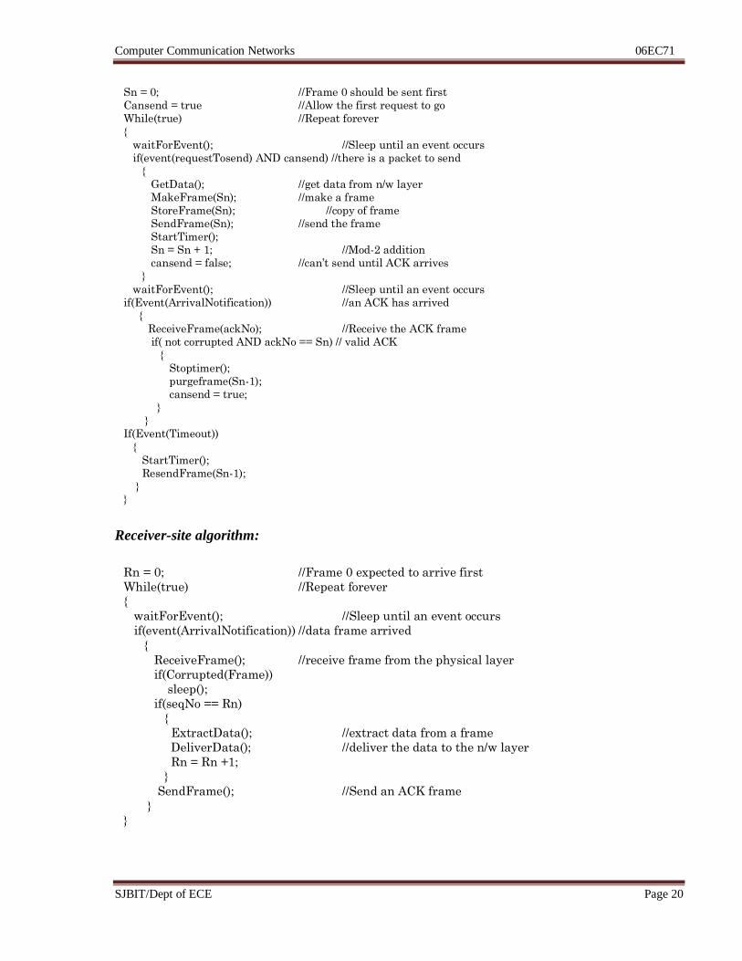
Receiver-site algorithm:
Sn = 0; //Frame 0 should be sent first
Cansend = true //Allow the first request to go
While(true) //Repeat forever
{
waitForEvent(); //Sleep until an event occurs
if(event(requestTosend) AND cansend) //there is a packet to send
{
GetData(); //get data from n/w layer
MakeFrame(Sn); //make a frame
StoreFrame(Sn); //copy of frame
SendFrame(Sn); //send the frame
StartTimer();
Sn = Sn + 1; //Mod-2 addition
cansend = false; //can’t send until ACK arrives
}
waitForEvent(); //Sleep until an event occurs
if(Event(ArrivalNotification)) //an ACK has arrived
{
ReceiveFrame(ackNo); //Receive the ACK frame
if( not corrupted AND ackNo == Sn) // valid ACK
{
Stoptimer();
purgeframe(Sn-1);
cansend = true;
}
}
If(Event(Timeout))
{
StartTimer();
ResendFrame(Sn-1);
} }
Rn = 0; //Frame 0 expected to arrive first
While(true) //Repeat forever
{
waitForEvent(); //Sleep until an event occurs
if(event(ArrivalNotification)) //data frame arrived
{
ReceiveFrame(); //receive frame from the physical layer
if(Corrupted(Frame))
sleep();
if(seqNo == Rn)
{
ExtractData(); //extract data from a frame
DeliverData(); //deliver the data to the n/w layer
Rn = Rn +1;
}
SendFrame(); //Send an ACK frame
}
}
Computer Communication Networks 06EC71
SJBIT/Dept of ECE Page 21
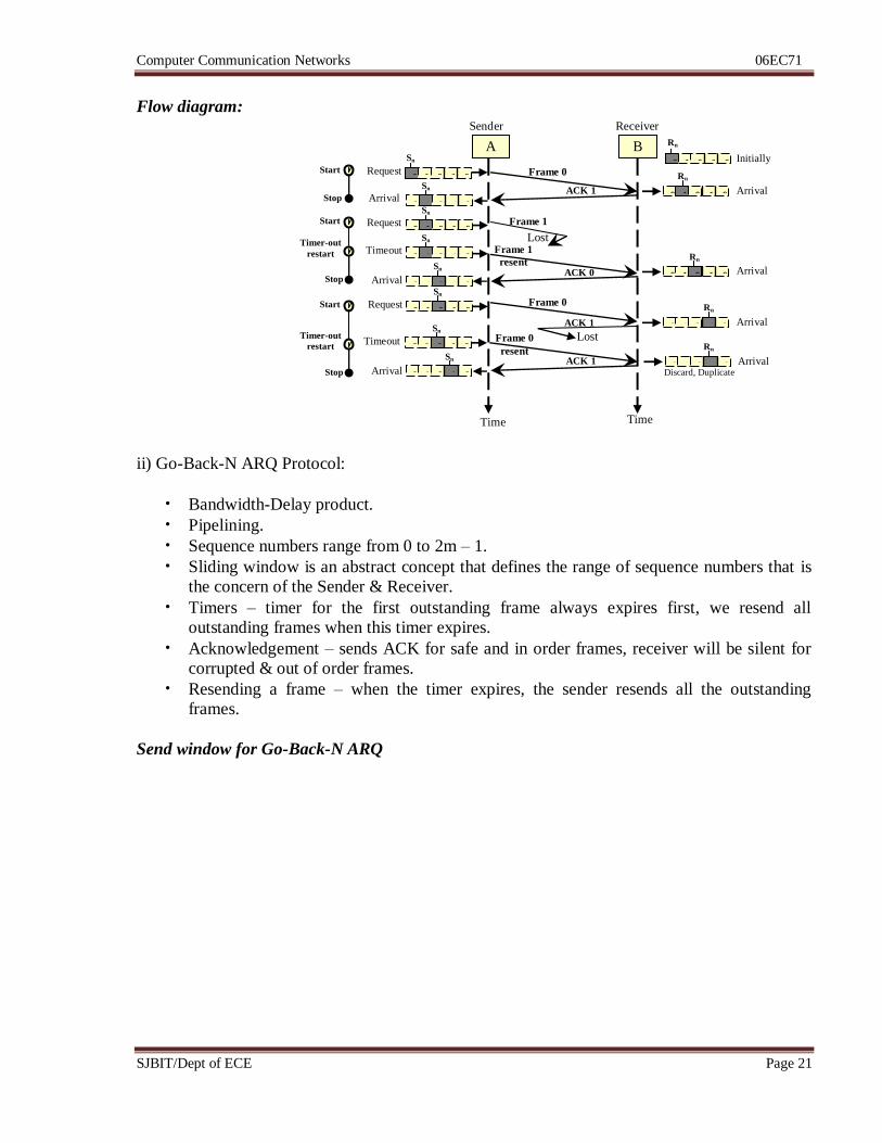
Flow diagram:
ii) Go-Back-N ARQ Protocol:
• Bandwidth-Delay product.
• Pipelining.
• Sequence numbers range from 0 to 2m – 1.
• Sliding window is an abstract concept that defines the range of sequence numbers that is
the concern of the Sender & Receiver.
• Timers – timer for the first outstanding frame always expires first, we resend all
outstanding frames when this timer expires.
• Acknowledgement – sends ACK for safe and in order frames, receiver will be silent for
corrupted & out of order frames.
• Resending a frame – when the timer expires, the sender resends all the outstanding
frames.
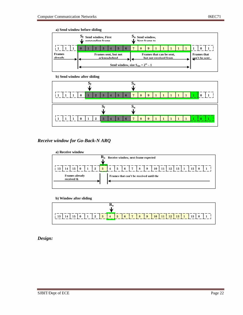
Send window for Go-Back-N ARQ
Arrival
A B
Time Time
Request Frame 0
Sender Receiver
ACK 1
0 1 0 1 0
Sn
Frame 1
Lost
0 1 0 1 0
Rn
0 1 0 1 0
Sn
Arrival
0 1 0 1 0
Sn
Request
0 1 0 1 0
Sn
Timeout Frame 1
resent ACK 0 Arrival
0 1 0 1 0
Rn
0 1 0 1 0
Sn
Arrival
0 1 0 1 0
Sn
Request Frame 0
Arrival 0 1 0 1 0
Rn
ACK 1
Lost Frame 0
resent 0 1 0 1 0
Sn
Timeout
ACK 1 Arrival 0 1 0 1 0
Rn
Discard, Duplicate Arrival 0 1 0 1 0
Sn
Start
Stop
Start
Timer-out
restart
Stop
Start
Timer-out
restart
Stop
0 1 0 1 0
Rn
Initially
Computer Communication Networks 06EC71
SJBIT/Dept of ECE Page 22
Receive window for Go-Back-N ARQ
Design:
1 0 1
5
1
4
1
3
1
2
1
1
1
0
9 8 7 6 5 4 3 2 1 0 1
5
1
4
1
3
Sn Send window,
Next frame to
send
Sf Send window, First
outstanding frame
Frames sent, but not
acknowledged
(outstanding)
Frames that can be sent,
but not received from
upper layer
Frames
already
acknowledged
Frames that
can’t be sent
Send window, size Ssize = 2m
– 1
1 0 1
5
1
4
1
3
1
2
1
1
1
0
9 8 7 6 5 4 3 2 1 0 1
5
1
4
1
3
Sn
b) Send window after sliding
Sf
a) Send window before sliding
1 0 1
5
1
4
1
3
1
2
1
1
1
0
9 8 7 6 5 4 3 2 1 0 1
5
1
4
1
3
Sn Sf
Receive window, next frame expected
Frames already
received &
acknowledged
Frames that can’t be received until the
window slides
1 0 15 1
4
13 12 11 10 9 8 7 6 5 4 3 2 1 0 15 14 13
Rn
b) Window after sliding
a) Receive window
1 0 15 1
4
13 12 11 10 9 8 7 6 5 4 2 1 0 15 14 13
Rn
3
Computer Communication Networks 06EC71
SJBIT/Dept of ECE Page 23
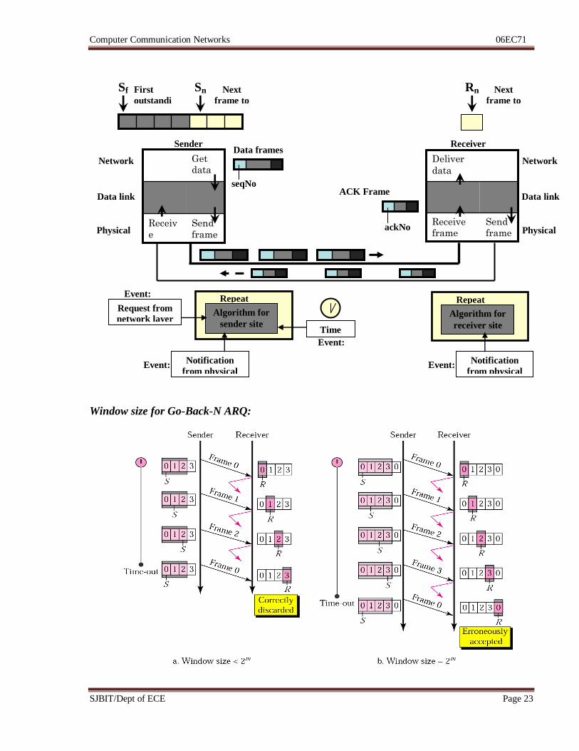
Window size for Go-Back-N ARQ:
Algorithm for
sender site
Repeat
forever
Data frames
Network
Data link
Physical
Network
Data link
Physical
Sender Receiver
Request from
network layer
Event:
Send frame
Receive frame
Deliver
data
Send
frame
Receiv
e
frame
Get data
ACK Frame
Notification
from physical
layer
Notification
from physical
layer
Event:
Algorithm for
receiver site
Repeat
forever
Event:
Sn Next
frame to
send
Rn Next
frame to
receive
Time
Out Event:
ackNo
seqNo
Sf First
outstandi
ng
Computer Communication Networks 06EC71
SJBIT/Dept of ECE Page 24
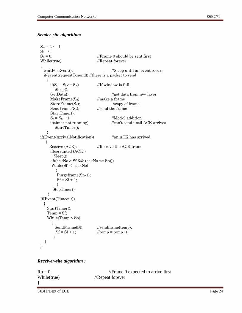
Sender-site algorithm:
Receiver-site algorithm :
Rn = 0; //Frame 0 expected to arrive first
While(true) //Repeat forever
{
Sw = 2m – 1;
Sf = 0;
Sn = 0; //Frame 0 should be sent first
While(true) //Repeat forever
{
waitForEvent(); //Sleep until an event occurs
if(event(requestTosend)) //there is a packet to send
{
if(Sn – Sf >= Sw) //If window is full
Sleep();
GetData(); //get data from n/w layer
MakeFrame(Sn); //make a frame
StoreFrame(Sn); //copy of frame
SendFrame(Sn); //send the frame
StartTimer();
Sn = Sn + 1; //Mod-2 addition
if(timer not running); //can’t send until ACK arrives
StartTimer();
}
if(Event(ArrivalNotification)) //an ACK has arrived
{
Receive (ACK); //Receive the ACK frame
if(corrupted (ACK))
Sleep();
if((ackNo > Sf && (ackNo <= Sn)))
While(Sf <= ackNo)
{
Purgeframe(Sn-1);
Sf = Sf + 1;
}
StopTimer();
}
If(Event(Timeout))
{
StartTimer();
Temp = Sf;
While(Temp < Sn)
{
SendFrame(Sf); //sendframe(temp);
Sf = Sf + 1; //temp = temp+1;
}
}
}
Computer Communication Networks 06EC71
SJBIT/Dept of ECE Page 25
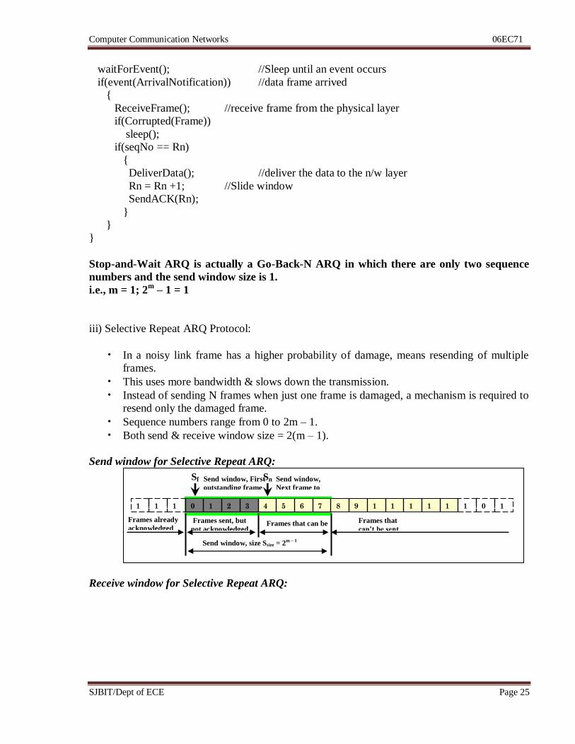
waitForEvent(); //Sleep until an event occurs
if(event(ArrivalNotification)) //data frame arrived
{
ReceiveFrame(); //receive frame from the physical layer
if(Corrupted(Frame))
sleep();
if(seqNo == Rn)
{
DeliverData(); //deliver the data to the n/w layer
Rn = Rn +1; //Slide window
SendACK(Rn);
}
}
}
Stop-and-Wait ARQ is actually a Go-Back-N ARQ in which there are only two sequence
numbers and the send window size is 1.
i.e., m = 1; 2m
– 1 = 1
iii) Selective Repeat ARQ Protocol:
• In a noisy link frame has a higher probability of damage, means resending of multiple
frames.
• This uses more bandwidth & slows down the transmission.
• Instead of sending N frames when just one frame is damaged, a mechanism is required to
resend only the damaged frame.
• Sequence numbers range from 0 to 2m – 1.
• Both send & receive window size = 2(m – 1).
Send window for Selective Repeat ARQ:
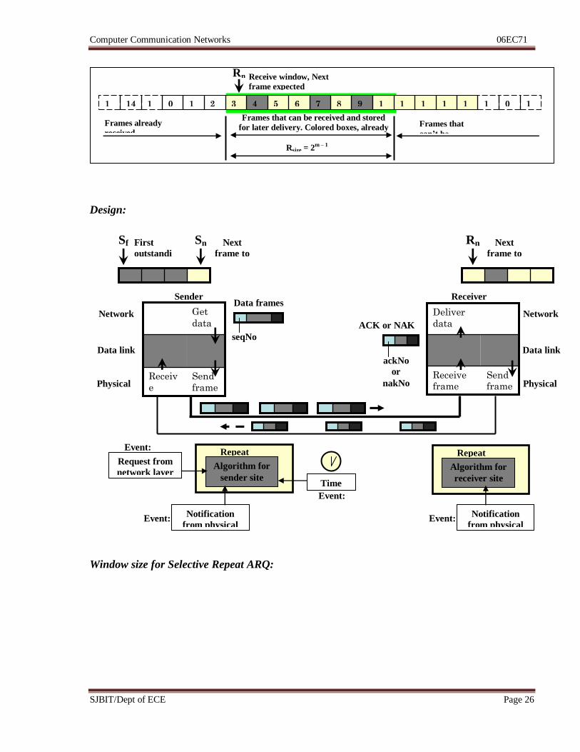
Receive window for Selective Repeat ARQ:
1 0 1
5
1
4
1
3
1
2
1
1
1
0
9 8 7 6 5 4 3 2 1 0 1
5
1
4
1
3
Sn Send window,
Next frame to
send
Sf Send window, First
outstanding frame
Frames sent, but
not acknowledged Frames that can be
sent
Frames already
acknowledged Frames that
can’t be sent
Send window, size Ssize = 2m – 1
Computer Communication Networks 06EC71
SJBIT/Dept of ECE Page 26
Design:
Window size for Selective Repeat ARQ:
1 0 1
5
1
4
1
3
1
2
1
1
1
0
9 8 7 6 5 4 3 2 1 0 1
5
14 1
3
Rn Receive window, Next
frame expected
Frames that can be received and stored
for later delivery. Colored boxes, already
received
Frames already
received Frames that
can’t be
received Rsize = 2
m – 1
Algorithm for
sender site
Repeat
forever
Data frames
Network
Data link
Physical
Network
Data link
Physical
Sender Receiver
Request from
network layer
Event:
Send frame
Receive frame
Deliver
data
Send
frame
Receiv
e
frame
Get
data
ACK or NAK
Notification
from physical
layer
Notification
from physical
layer
Event:
Algorithm for
receiver site
Repeat
forever
Event:
Sn Next
frame to
send
Rn Next
frame to
receive
Time
Out Event:
ackNo
or
nakNo
seqNo
Sf First
outstandi
ng
Computer Communication Networks 06EC71
SJBIT/Dept of ECE Page 27
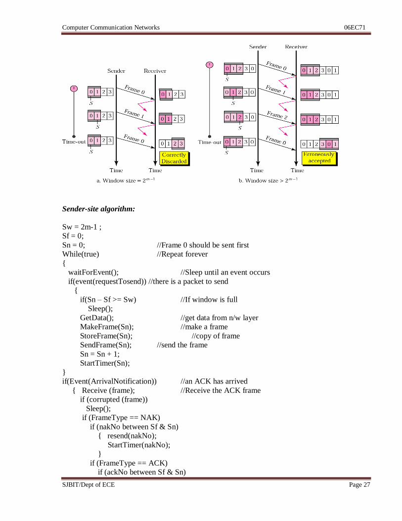
Sender-site algorithm:
Sw = 2m-1 ;
Sf = 0;
Sn = 0; //Frame 0 should be sent first
While(true) //Repeat forever
{
waitForEvent(); //Sleep until an event occurs
if(event(requestTosend)) //there is a packet to send
{
if(Sn – Sf >= Sw) //If window is full
Sleep();
GetData(); //get data from n/w layer
MakeFrame(Sn); //make a frame
StoreFrame(Sn); //copy of frame
SendFrame(Sn); //send the frame
Sn = Sn + 1;
StartTimer(Sn);
}
if(Event(ArrivalNotification)) //an ACK has arrived
{ Receive (frame); //Receive the ACK frame
if (corrupted (frame))
Sleep();
if (FrameType == NAK)
if (nakNo between Sf & Sn)
{ resend(nakNo);
StartTimer(nakNo);
}
if (FrameType == ACK)
if (ackNo between Sf & Sn)
Computer Communication Networks 06EC71
SJBIT/Dept of ECE Page 28
{ While (Sf <= ackNo)
{
Purge (Sf);
StopTimer (Sf);
Sf = Sf + 1;
}
}
}
If (Event (Timeout (t)))
{
StartTimer(t);
SendFrame(t);
}
}
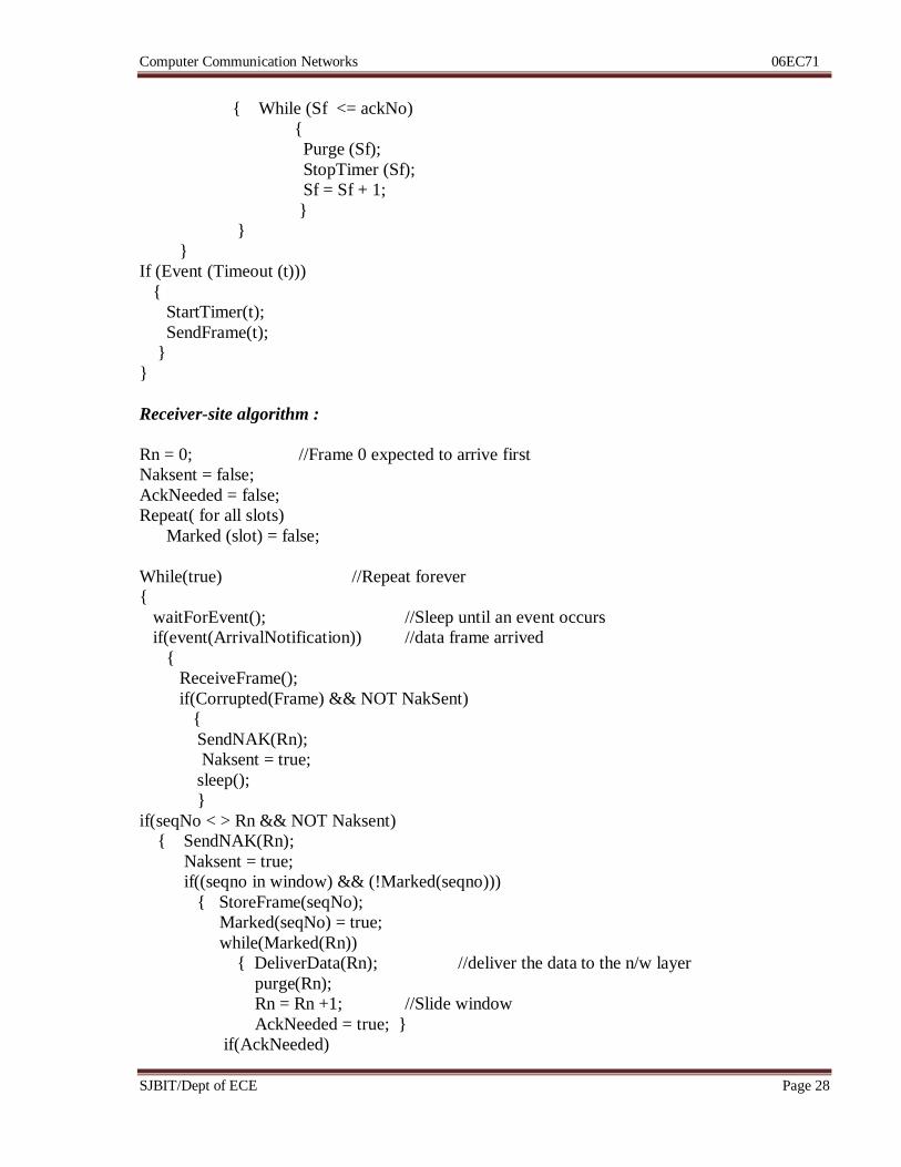
Receiver-site algorithm :
Rn = 0; //Frame 0 expected to arrive first
Naksent = false;
AckNeeded = false;
Repeat( for all slots)
Marked (slot) = false;
While(true) //Repeat forever
{
waitForEvent(); //Sleep until an event occurs
if(event(ArrivalNotification)) //data frame arrived
{
ReceiveFrame();
if(Corrupted(Frame) && NOT NakSent)
{
SendNAK(Rn);
Naksent = true;
sleep();
}
if(seqNo < > Rn && NOT Naksent)
{ SendNAK(Rn);
Naksent = true;
if((seqno in window) && (!Marked(seqno)))
{ StoreFrame(seqNo);
Marked(seqNo) = true;
while(Marked(Rn))
{ DeliverData(Rn); //deliver the data to the n/w layer
purge(Rn);
Rn = Rn +1; //Slide window
AckNeeded = true; }
if(AckNeeded)
Computer Communication Networks 06EC71
SJBIT/Dept of ECE Page 29
{ SendACK(Rn);
AckNeeded = false;
NakSent = false; }
}
}
}
}
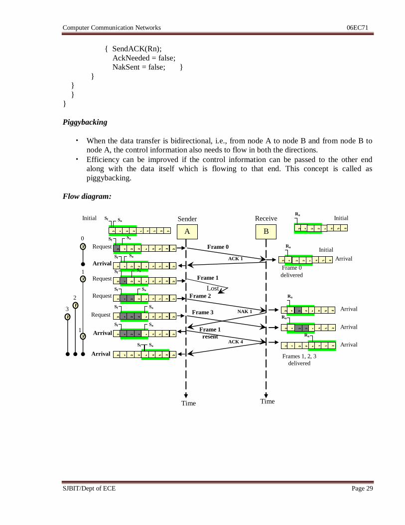
Piggybacking
• When the data transfer is bidirectional, i.e., from node A to node B and from node B to
node A, the control information also needs to flow in both the directions.
• Efficiency can be improved if the control information can be passed to the other end
along with the data itself which is flowing to that end. This concept is called as
piggybacking.
Flow diagram:
Arrival
A B
Time Time
Request Frame 0
Sender Receive
r
ACK 1
4 3 0 1 2
Sf
Frame 1
Lost
Arrival
Request
Request Frame 2
NAK 1 Arrival
Request
Arrival
Frame 3
Arrival Frame 1
resent ACK 4
Arrival
Arrival
Rn
Initial
0 5 6 7
Sn
4 3 0 1 2 0 5 6 7
Sn
4 3 0 1 2 5 6 7
Initial Sf
4 3 0 1 2 0 5 6 7
Sf Sn
4 3 0 1 2 0 5 6 7
Sf Sn
4 3 0 1 2 0 5 6 7
Sf Sn
4 3 0 1 2 0 5 6 7
Sf Sn
4 3 0 1 2 0 5 6 7
Sf Sn
4 3 0 1 2 0 5 6 7
Sf Sn
0
1
1
2
3
Rn
Initial
4 3 0 1 2 5 6 7
Rn
4 3 0 1 2 5 6 7 Rn
4 3 0 1 2 5 6 7
4 3 0 1 2 5 6 7
Rn
Frame 0
delivered
Frames 1, 2, 3
delivered
Computer Communication Networks 06EC71
SJBIT/Dept of ECE Page 30
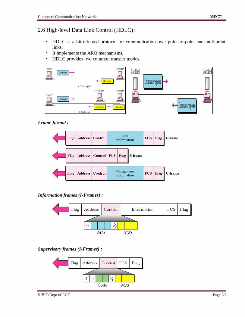
2.6 High-level Data Link Control (HDLC):
• HDLC is a bit-oriented protocol for communication over point-to-point and multipoint
links.
• It implements the ARQ mechanisms.
• HDLC provides two common transfer modes.
Frame format :
Information frames (I-Frames) :
Supervisory frames (I-Frames) :
Computer Communication Networks 06EC71
SJBIT/Dept of ECE Page 31
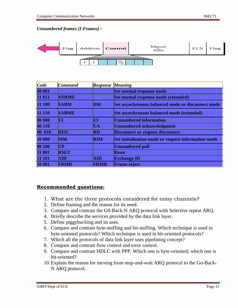
Unnumbered frames (I-Frames) :
Code Command Response Meaning
00 001 Set normal response mode
11 011 SNRME Set normal response mode (extended)
11 100 SABM DM Set asynchronous balanced mode or disconnect mode
11 110 SABME Set asynchronous balanced mode (extended)
00 000 UI UI Unnumbered information
00 110 UA Unnumbered acknowledgment
00 010 DISC RD Disconnect or request disconnect
10 000 SIM RIM Set initialization mode or request information mode
00 100 UP Unnumbered poll
11 001 RSET Reset
11 101 XID XID Exchange ID
10 001 FRMR FRMR Frame reject
Recommended questions:
1. What are the three protocols considered for noisy channels? 2. Define framing and the reason for its need.
3. Compare and contrast the G0-Back-N ARQ protocol with Selective repeat ARQ.
4. Briefly describe the services provided by the data link layer.
5. Define piggybacking and its uses.
6. Compare and contrast byte-stuffing and bit-stuffing. Which technique is used in
byte-oriented protocols? Which technique is used in bit-oriented protocols?
7. Which all the protocols of data link layer uses pipelining concept?
8. Compare and contrast flow control and error control.
9. Compare and contrast HDLC with PPP. Which one is byte-oriented; which one is
bit-oriented?
10. Explain the reason for moving from stop-and-wait ARQ protocol to the Go-Back-
N ARQ protocol.
Computer Communication Networks 06EC71
SJBIT/Dept of ECE Page 32
Unit 3: Multiple Accesses Hrs: 06
Syllabus:
Random access, Controlled access, channelization
Recommended readings:
Text Book: Data Communication & Networking, B Forouzan, 4e, TMH
Chapter 12 – page 363 to 396
Computer Communication Networks 06EC71
SJBIT/Dept of ECE Page 33
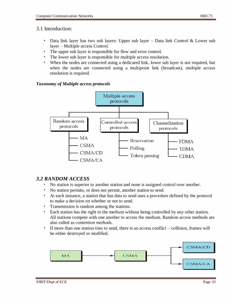
3.1 Introduction:
• Data link layer has two sub layers: Upper sub layer – Data link Control & Lower sub
layer – Multiple access Control.
• The upper sub layer is responsible for flow and error control.
• The lower sub layer is responsible for multiple access resolution.
• When the nodes are connected using a dedicated link, lower sub layer is not required, but
when the nodes are connected using a multipoint link (broadcast), multiple access
resolution is required.
Taxonomy of Multiple access protocols
3.2 RANDOM ACCESS • No station is superior to another station and none is assigned control over another.
• No station permits, or does not permit, another station to send.
• At each instance, a station that has data to send uses a procedure defined by the protocol
to make a decision on whether or not to send.
• Transmission is random among the stations.
• Each station has the right to the medium without being controlled by any other station.
All stations compete with one another to access the medium. Random access methods are
also called as contention methods.
• If more than one station tries to send, there is an access conflict – collision, frames will
be either destroyed or modified.
Computer Communication Networks 06EC71
SJBIT/Dept of ECE Page 34
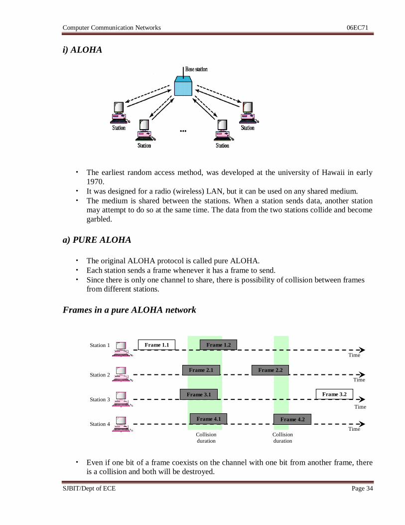
i) ALOHA
• The earliest random access method, was developed at the university of Hawaii in early
1970.
• It was designed for a radio (wireless) LAN, but it can be used on any shared medium.
• The medium is shared between the stations. When a station sends data, another station
may attempt to do so at the same time. The data from the two stations collide and become
garbled.
a) PURE ALOHA
• The original ALOHA protocol is called pure ALOHA.
• Each station sends a frame whenever it has a frame to send.
• Since there is only one channel to share, there is possibility of collision between frames
from different stations.
Frames in a pure ALOHA network
• Even if one bit of a frame coexists on the channel with one bit from another frame, there
is a collision and both will be destroyed.
Frame 1.1 Frame 1.2
Frame 2.1
Frame 3.1
Frame 4.1 Frame 4.2
Frame 2.2
Frame 3.2
Collision
duration
Collision
duration
Station 1
Station 2
Station 3
Station 4 Time
Time
Time
Time
Computer Communication Networks 06EC71
SJBIT/Dept of ECE Page 35
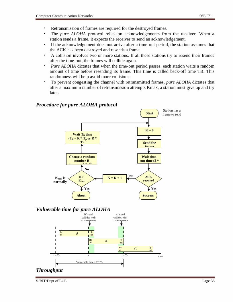
• Retransmission of frames are required for the destroyed frames.
• The pure ALOHA protocol relies on acknowledgements from the receiver. When a
station sends a frame, it expects the receiver to send an acknowledgement.
• If the acknowledgement does not arrive after a time-out period, the station assumes that
the ACK has been destroyed and resends a frame.
• A collision involves two or more stations. If all these stations try to resend their frames
after the time-out, the frames will collide again.
• Pure ALOHA dictates that when the time-out period passes, each station waits a random
amount of time before resending its frame. This time is called back-off time TB. This
randomness will help avoid more collisions.
• To prevent congesting the channel with retransmitted frames, pure ALOHA dictates that
after a maximum number of retransmission attempts Kmax, a station must give up and try
later.
Procedure for pure ALOHA protocol
Vulnerable time for pure ALOHA
Throughput
K = 0
Start
Send the
frame
Wait time-
out time (2 *
Tp)
ACK
received
?
Success Abort
K >
Kmax
Choose a random
number R
between 0 & 2k –
1
Wait TB time
(TB = R * Tp or R *
Tfr
K = K + 1
Station has a frame to send
Yes
No
No
Yes
Kmax is
normally
15
B Be
gi
n
E
nd
A Be
gi
n
E
nd
C Be
gi
n
E
nd
B’ s end
collides with
A’s beginning
A’ s end
collides with
C’s beginning
Vulnerable time = 2 * Tfr
t – Tfr t + Tfr t time
Computer Communication Networks 06EC71
SJBIT/Dept of ECE Page 36
G = average number of frames generated by the system during one frame transmission time.
Successful transmissions for pure ALOHA is
S = G * e-2G
The maximum throughput, Smax is for G = ½. i.e., Smax = 0.184 = 18.4%.
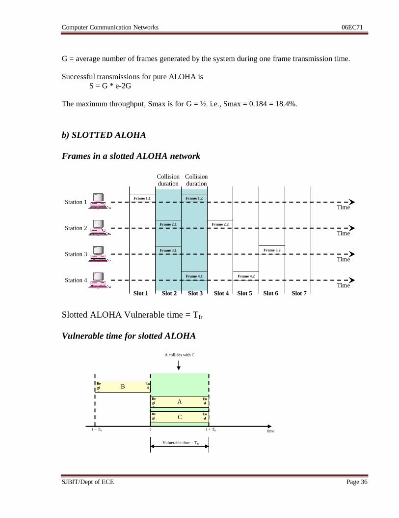
b) SLOTTED ALOHA
Frames in a slotted ALOHA network
Slotted ALOHA Vulnerable time = Tfr
Vulnerable time for slotted ALOHA
Frame 1.1
Collision duration
Collision duration
Time
Time
Frame 1.2
Frame 2.1 Frame 2.2
Frame 3.1 Frame 3.2
Frame 4.1 Frame 4.2
Slot 1 Slot 2 Slot 3 Slot 4 Slot 5 Slot 6 Slot 7
Time
Time
Station 1
Station 2
Station 3
Station 4
B Be
gi
n
En
d
A Be
gi
n
En
d
C Be
gi
n
En
d
A collides with C
Vulnerable time = Tfr
t – Tfr t + Tfr t time
Computer Communication Networks 06EC71
SJBIT/Dept of ECE Page 37
Throughput
G = average number of frames generated by the system during one frame transmission time.
Successful transmissions for pure ALOHA is
S = G * e-G
The maximum throughput, Smax is for G =1 i.e., Smax = 0.368 = 36.8%.
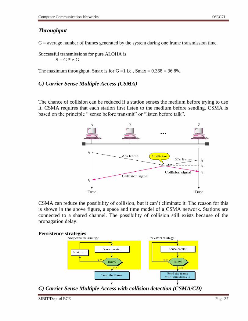
C) Carrier Sense Multiple Access (CSMA)
The chance of collision can be reduced if a station senses the medium before trying to use
it. CSMA requires that each station first listen to the medium before sending. CSMA is
based on the principle “ sense before transmit” or “listen before talk”.
CSMA can reduce the possibility of collision, but it can’t eliminate it. The reason for this
is shown in the above figure, a space and time model of a CSMA network. Stations are
connected to a shared channel. The possibility of collision still exists because of the
propagation delay.
Persistence strategies
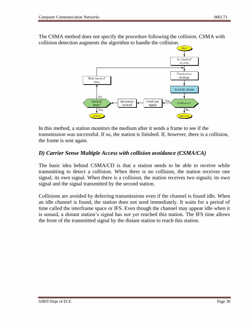
C) Carrier Sense Multiple Access with collision detection (CSMA/CD)
Computer Communication Networks 06EC71
SJBIT/Dept of ECE Page 38
The CSMA method does not specify the procedure following the collision. CSMA with
collision detection augments the algorithm to handle the collision.
In this method, a station monitors the medium after it sends a frame to see if the
transmission was successful. If so, the station is finished. If, however, there is a collision,
the frame is sent again.
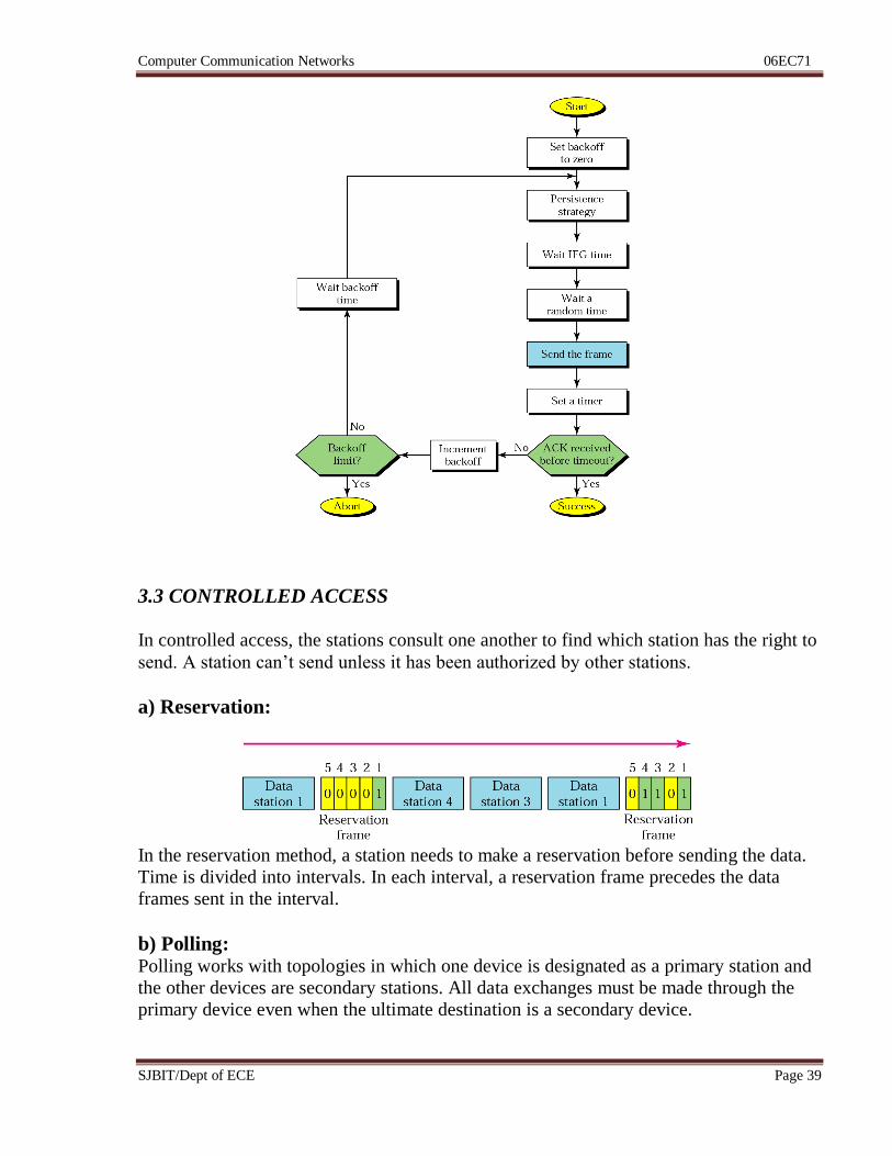
D) Carrier Sense Multiple Access with collision avoidance (CSMA/CA)
The basic idea behind CSMA/CD is that a station needs to be able to receive while
transmitting to detect a collision. When there is no collision, the station receives one
signal; its own signal. When there is a collision, the station receives two signals; its own
signal and the signal transmitted by the second station.
Collisions are avoided by deferring transmissions even if the channel is found idle. When
an idle channel is found, the station does not send immediately. It waits for a period of
time called the interframe space or IFS. Even though the channel may appear idle when it
is sensed, a distant station’s signal has not yet reached this station. The IFS time allows
the front of the transmitted signal by the distant station to reach this station.
Computer Communication Networks 06EC71
SJBIT/Dept of ECE Page 39
3.3 CONTROLLED ACCESS
In controlled access, the stations consult one another to find which station has the right to
send. A station can’t send unless it has been authorized by other stations.
a) Reservation:
In the reservation method, a station needs to make a reservation before sending the data.
Time is divided into intervals. In each interval, a reservation frame precedes the data
frames sent in the interval.
b) Polling: Polling works with topologies in which one device is designated as a primary station and
the other devices are secondary stations. All data exchanges must be made through the
primary device even when the ultimate destination is a secondary device.
Computer Communication Networks 06EC71
SJBIT/Dept of ECE Page 40
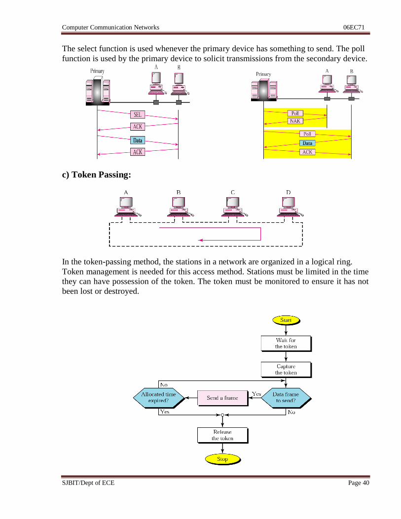
The select function is used whenever the primary device has something to send. The poll
function is used by the primary device to solicit transmissions from the secondary device.
c) Token Passing:
In the token-passing method, the stations in a network are organized in a logical ring.
Token management is needed for this access method. Stations must be limited in the time
they can have possession of the token. The token must be monitored to ensure it has not
been lost or destroyed.
Computer Communication Networks 06EC71
SJBIT/Dept of ECE Page 41
3.4 CHANNELIZATION
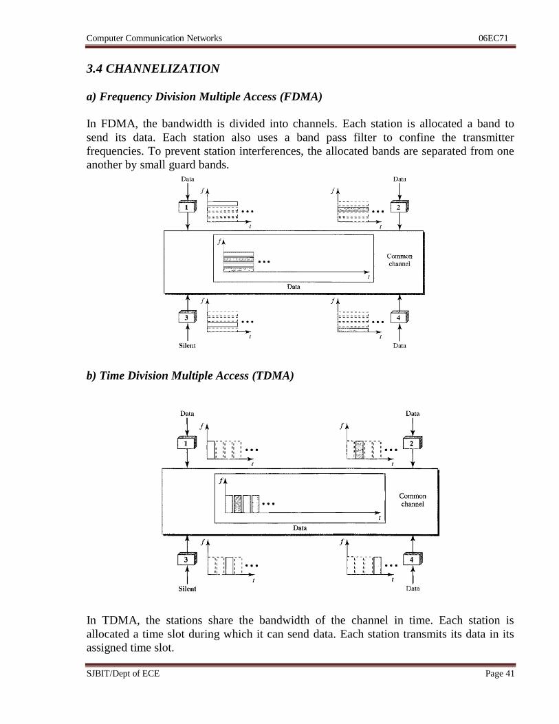
a) Frequency Division Multiple Access (FDMA)
In FDMA, the bandwidth is divided into channels. Each station is allocated a band to
send its data. Each station also uses a band pass filter to confine the transmitter
frequencies. To prevent station interferences, the allocated bands are separated from one
another by small guard bands.
b) Time Division Multiple Access (TDMA)
In TDMA, the stations share the bandwidth of the channel in time. Each station is
allocated a time slot during which it can send data. Each station transmits its data in its
assigned time slot.
Computer Communication Networks 06EC71
SJBIT/Dept of ECE Page 42
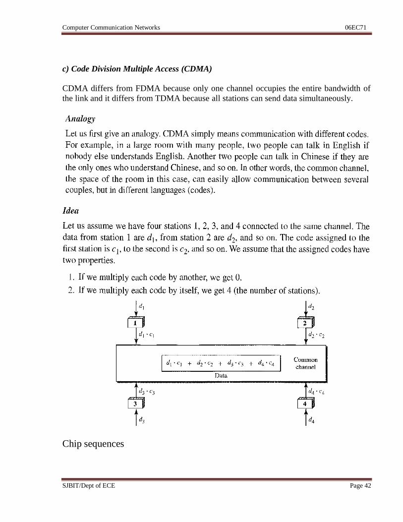
c) Code Division Multiple Access (CDMA)
CDMA differs from FDMA because only one channel occupies the entire bandwidth of
the link and it differs from TDMA because all stations can send data simultaneously.
Chip sequences
Computer Communication Networks 06EC71
SJBIT/Dept of ECE Page 43
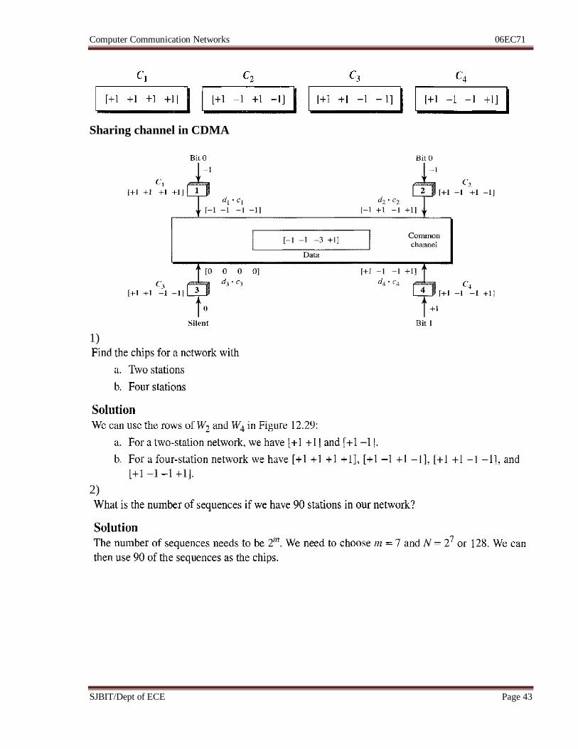
Sharing channel in CDMA
1)
2)
Computer Communication Networks 06EC71
SJBIT/Dept of ECE Page 44
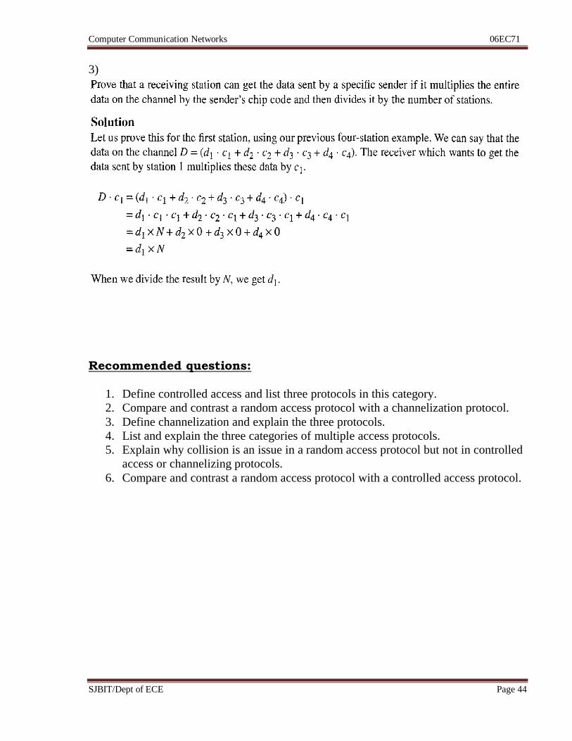
3)
Recommended questions:
1. Define controlled access and list three protocols in this category.
2. Compare and contrast a random access protocol with a channelization protocol.
3. Define channelization and explain the three protocols.
4. List and explain the three categories of multiple access protocols.
5. Explain why collision is an issue in a random access protocol but not in controlled
access or channelizing protocols.
6. Compare and contrast a random access protocol with a controlled access protocol.
Computer Communication Networks 06EC71
SJBIT/Dept of ECE Page 45
Unit 4: Hrs: 07
Syllabus:
IEEE standards, standard Ethernet, changes in the standards, Fast Ethernet, Gigabit
Ethernet, Wireless LAN IEEE 802.11
Recommended readings:
Text Book: Data Communication & Networking, B Forouzan, 4e, TMH
Chapter 13 – page 395 to 417
Chapter 14 – page 421 to 434
Computer Communication Networks 06EC71
SJBIT/Dept of ECE Page 46
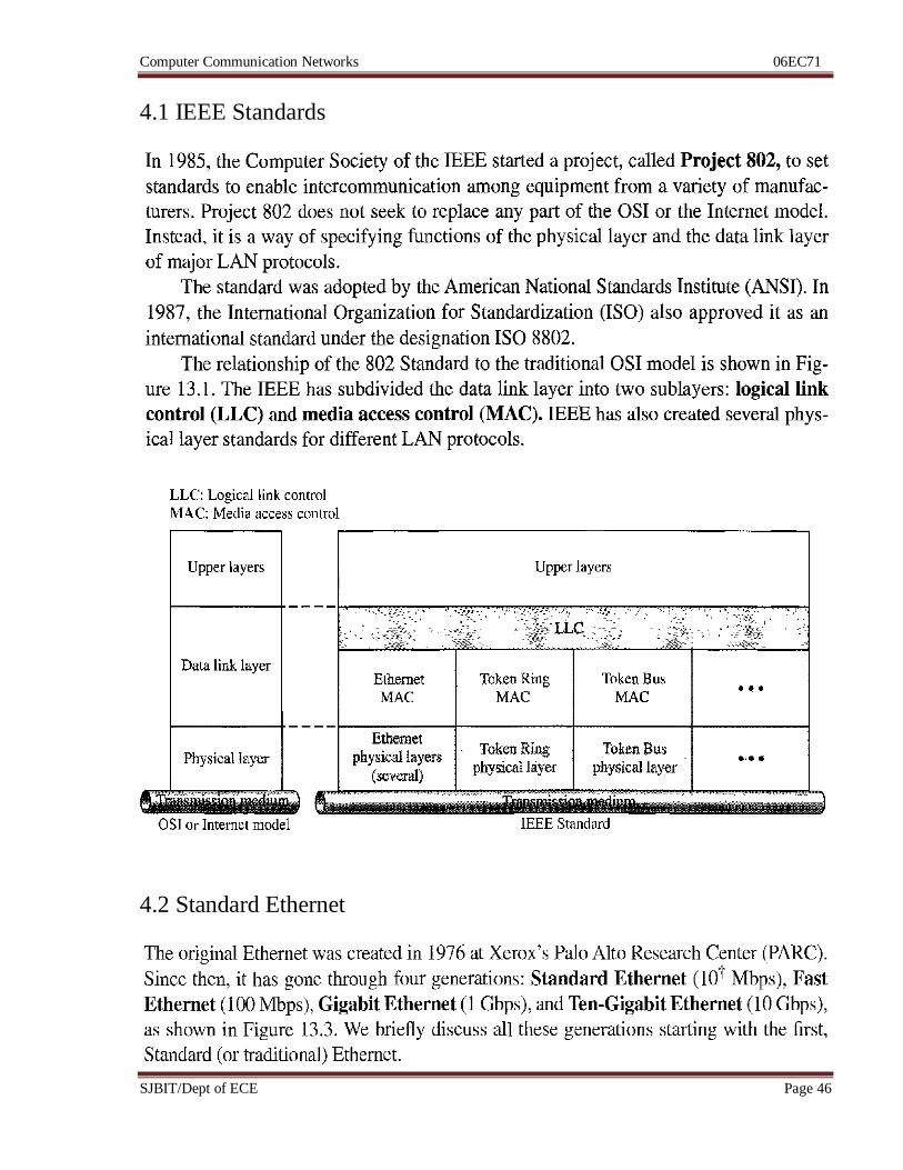
4.1 IEEE Standards
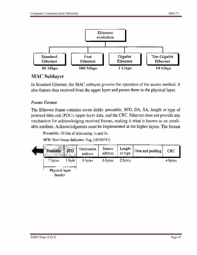
4.2 Standard Ethernet
Computer Communication Networks 06EC71
SJBIT/Dept of ECE Page 47
Computer Communication Networks 06EC71
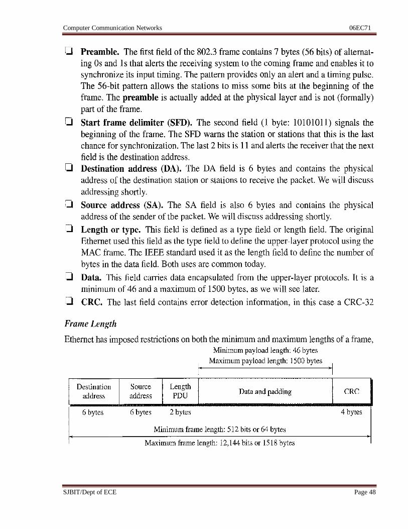
SJBIT/Dept of ECE Page 48
Computer Communication Networks 06EC71
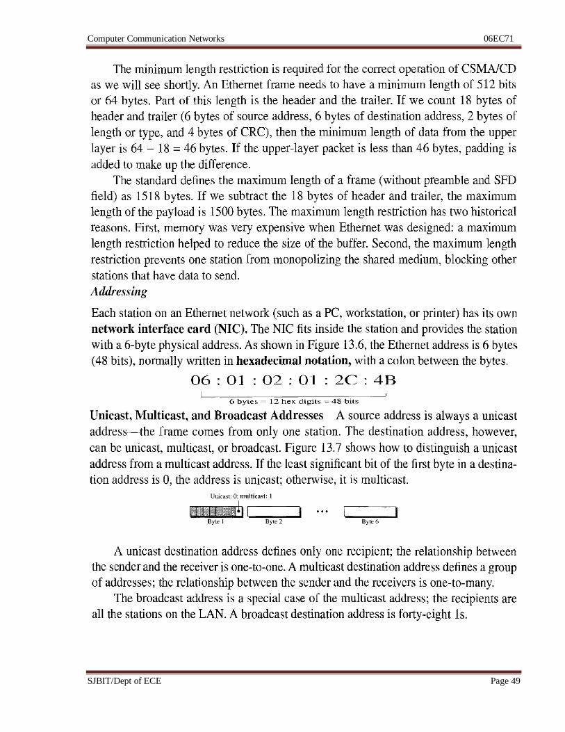
SJBIT/Dept of ECE Page 49
Computer Communication Networks 06EC71
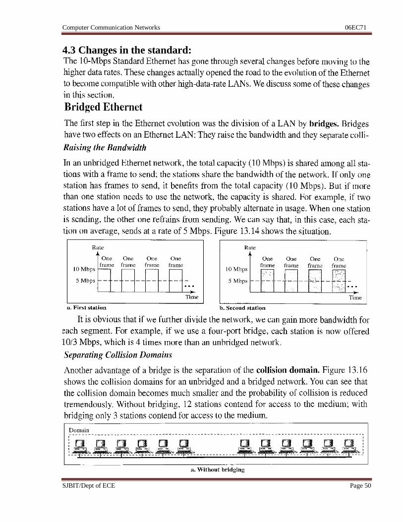
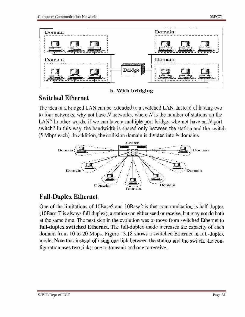
SJBIT/Dept of ECE Page 50
4.3 Changes in the standard:
Computer Communication Networks 06EC71
SJBIT/Dept of ECE Page 51
Computer Communication Networks 06EC71
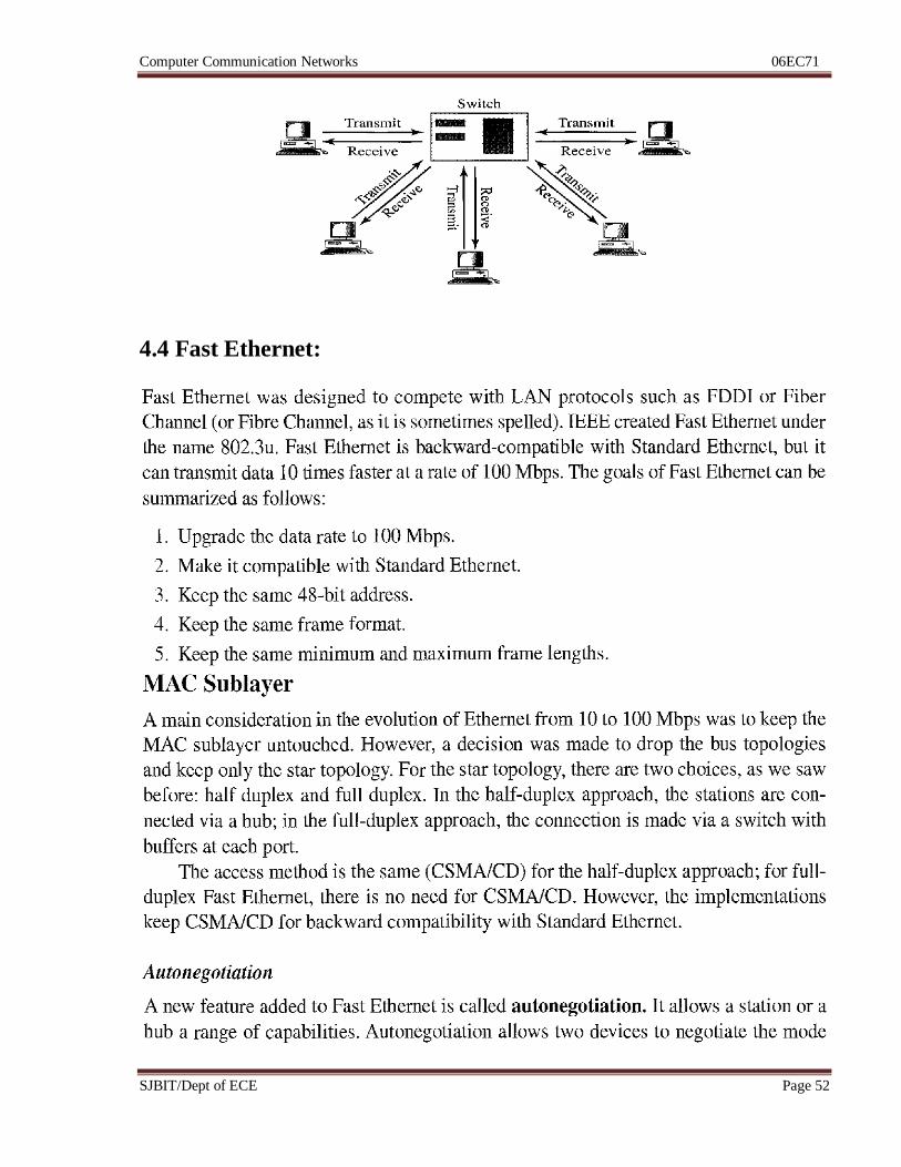
SJBIT/Dept of ECE Page 52
4.4 Fast Ethernet:
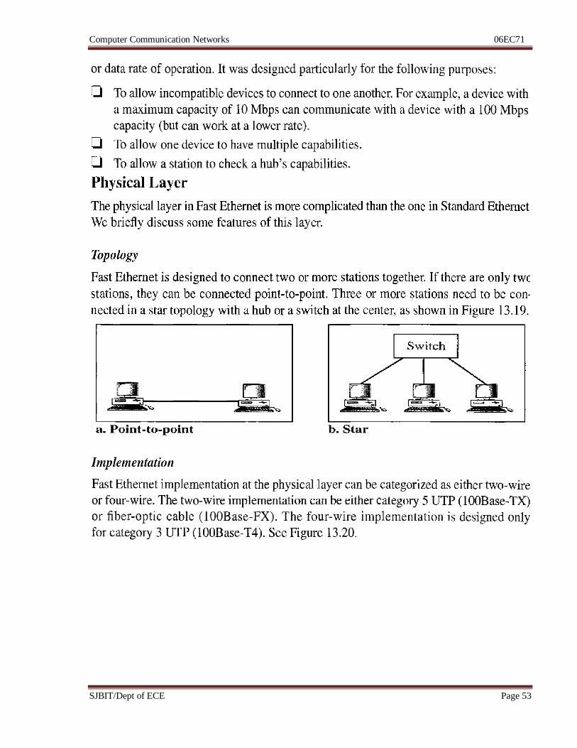
Computer Communication Networks 06EC71
SJBIT/Dept of ECE Page 53
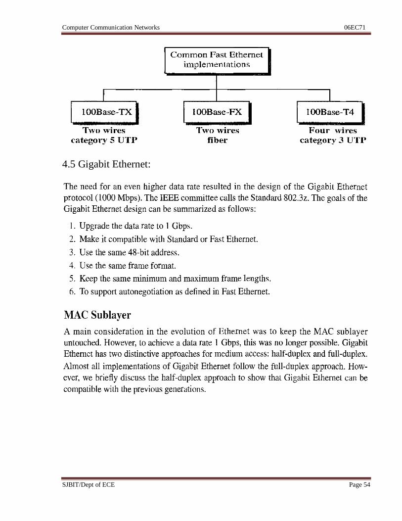
Computer Communication Networks 06EC71
SJBIT/Dept of ECE Page 54
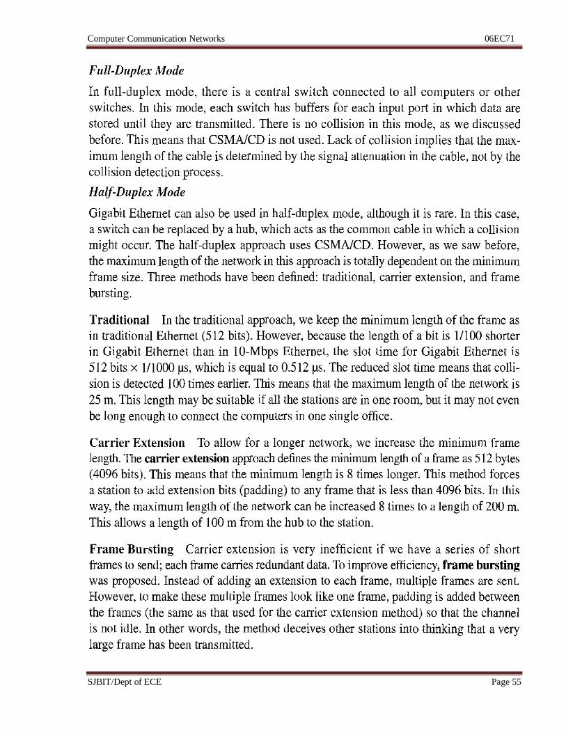
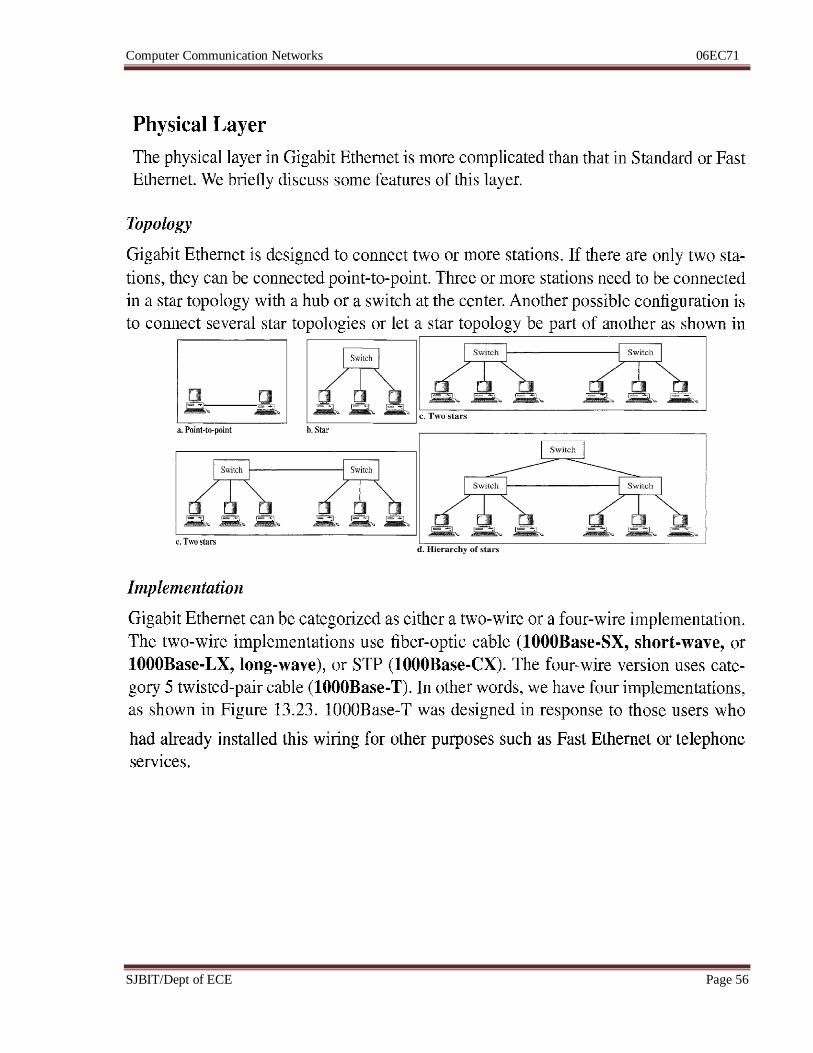
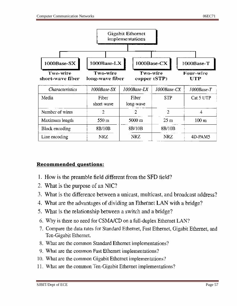
4.5 Gigabit Ethernet:
Computer Communication Networks 06EC71
SJBIT/Dept of ECE Page 55
Computer Communication Networks 06EC71
SJBIT/Dept of ECE Page 56
Computer Communication Networks 06EC71
SJBIT/Dept of ECE Page 57
Recommended questions:
Computer Communication Networks 06EC71
SJBIT/Dept of ECE Page 58
PART B
Unit 5: Hrs: 06
Syllabus:
Connecting LANs, Backbone and virtual LANs, Connecting devices, Backbone
networks, Virtual LANs.
Recommended readings:
Text Book: Data Communication & Networking, B Forouzan, 4e, TMH
Chapter 15 – page 445 to 463
Computer Communication Networks 06EC71
SJBIT/Dept of ECE Page 59
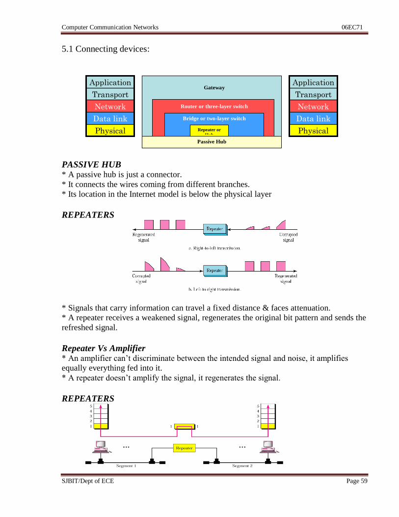
5.1 Connecting devices:
PASSIVE HUB * A passive hub is just a connector.
* It connects the wires coming from different branches.
* Its location in the Internet model is below the physical layer
REPEATERS
* Signals that carry information can travel a fixed distance & faces attenuation.
* A repeater receives a weakened signal, regenerates the original bit pattern and sends the
refreshed signal.
Repeater Vs Amplifier * An amplifier can’t discriminate between the intended signal and noise, it amplifies
equally everything fed into it.
* A repeater doesn’t amplify the signal, it regenerates the signal.
REPEATERS
Physical
Data link
Network
Transport
Application
Physical
Data link
Network
Transport
Application
Passive Hub
Repeater or
Hub
Bridge or two-layer switch
Router or three-layer switch
Gateway
Computer Communication Networks 06EC71
SJBIT/Dept of ECE Page 60
* A repeater is a device that operates only in the physical layer.
* A repeater can extend the physical length of a LAN.
* Repeater doesn’t connect two LANs, & of different protocols, it connects two segments
of same LAN.
* The location of a repeater on a link is vital.
* Repeaters overcome the restriction of 10Base5 Ethernet.
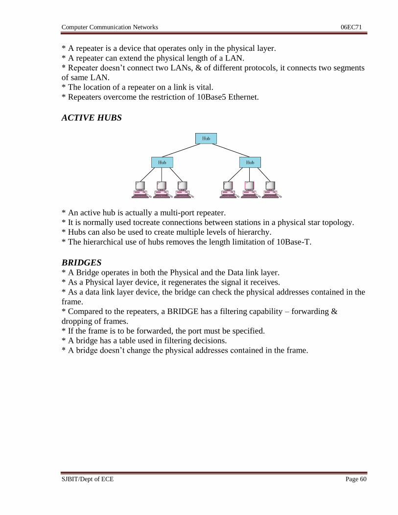
ACTIVE HUBS
* An active hub is actually a multi-port repeater.
* It is normally used tocreate connections between stations in a physical star topology.
* Hubs can also be used to create multiple levels of hierarchy.
* The hierarchical use of hubs removes the length limitation of 10Base-T.
BRIDGES * A Bridge operates in both the Physical and the Data link layer.
* As a Physical layer device, it regenerates the signal it receives.
* As a data link layer device, the bridge can check the physical addresses contained in the
frame.
* Compared to the repeaters, a BRIDGE has a filtering capability – forwarding &
dropping of frames.
* If the frame is to be forwarded, the port must be specified.
* A bridge has a table used in filtering decisions.
* A bridge doesn’t change the physical addresses contained in the frame.
Computer Communication Networks 06EC71
SJBIT/Dept of ECE Page 61
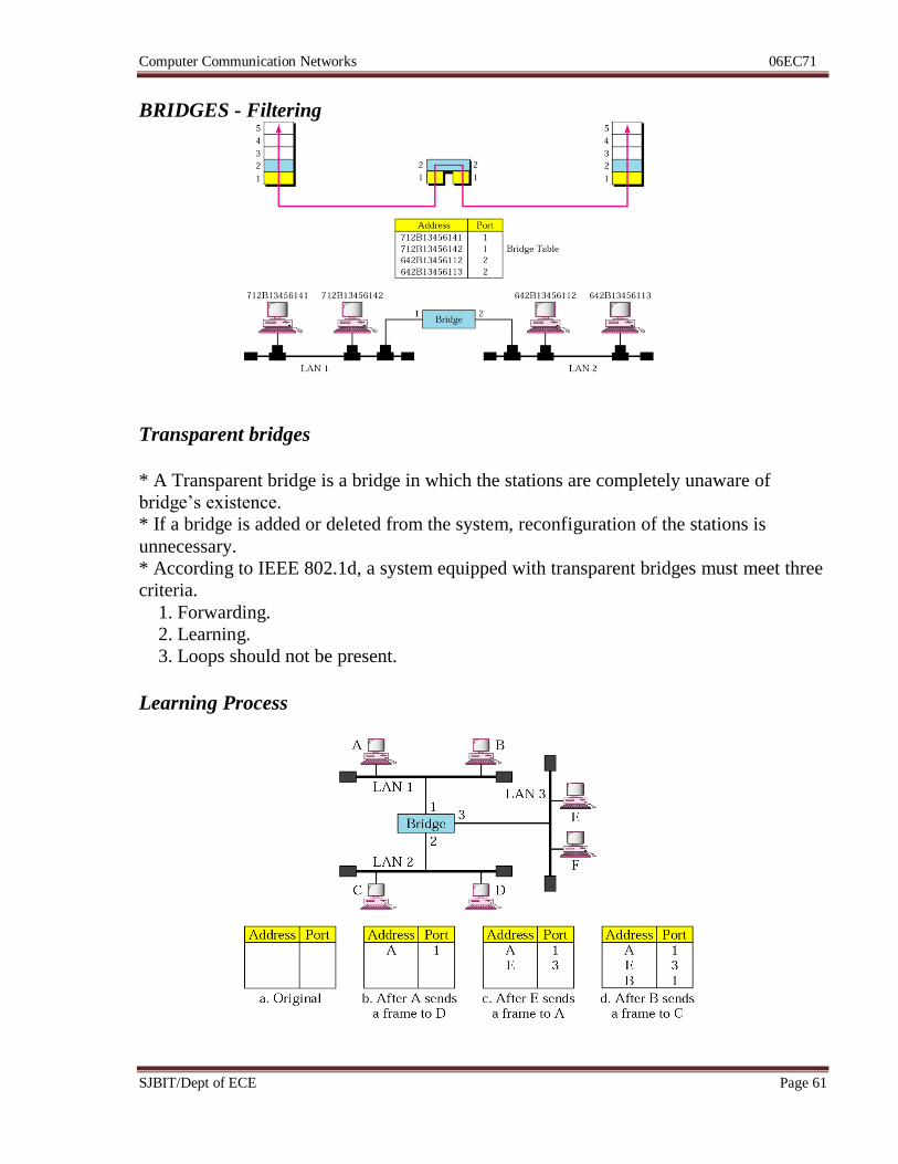
BRIDGES - Filtering
Transparent bridges
* A Transparent bridge is a bridge in which the stations are completely unaware of
bridge’s existence.
* If a bridge is added or deleted from the system, reconfiguration of the stations is
unnecessary.
* According to IEEE 802.1d, a system equipped with transparent bridges must meet three
criteria.
1. Forwarding.
2. Learning.
3. Loops should not be present.
Learning Process
Computer Communication Networks 06EC71
SJBIT/Dept of ECE Page 62
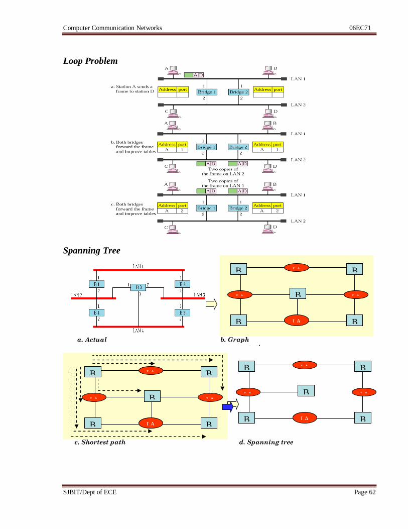
Loop Problem
Spanning Tree
B
1
B
4
B
2
B
5
LAN 4
LA
N 1
LAN 2
LAN 3
B
3
B
1
B
4
B
2
B
5
LAN 4
LAN 1
LAN 2
LAN 3
B
3
B
1
B
4
B
2
B
5
LAN 4
LA
N 1
LAN 2
LAN 3
B
3
a. Actual
system
b. Graph
representation
c. Shortest path d. Spanning tree
Computer Communication Networks 06EC71
SJBIT/Dept of ECE Page 63
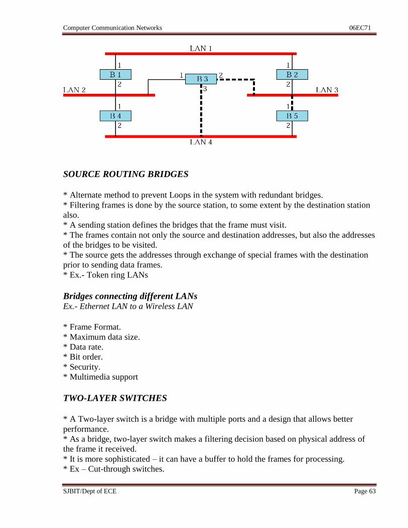
SOURCE ROUTING BRIDGES
* Alternate method to prevent Loops in the system with redundant bridges.
* Filtering frames is done by the source station, to some extent by the destination station
also.
* A sending station defines the bridges that the frame must visit.
* The frames contain not only the source and destination addresses, but also the addresses
of the bridges to be visited.
* The source gets the addresses through exchange of special frames with the destination
prior to sending data frames.
* Ex.- Token ring LANs
Bridges connecting different LANs Ex.- Ethernet LAN to a Wireless LAN
* Frame Format.
* Maximum data size.
* Data rate.
* Bit order.
* Security.
* Multimedia support
TWO-LAYER SWITCHES
* A Two-layer switch is a bridge with multiple ports and a design that allows better
performance.
* As a bridge, two-layer switch makes a filtering decision based on physical address of
the frame it received.
* It is more sophisticated – it can have a buffer to hold the frames for processing.
* Ex – Cut-through switches.
Computer Communication Networks 06EC71
SJBIT/Dept of ECE Page 64
ROUTERS or THREE-LAYER SWITCH
* A ROUTER is a three-layer device that routes packets based on their logical addresses.
* A router normally connects LANs & WANs in the internet and has a routing table that
is used for making decisions about the route.
* the routing tables are normally dynamic and are updated using routing protocols.
** A Three-Layer switch is a router, but a faster and more sophisticated.
GATEWAY
* A GATEWAY is normally a computer that operates in all five layers of the internet
model and seven layers of the OSI model.
* A Gateway takes an application message, reads it and interprets it – means it can be
used as a connecting device between two internetworks that use different models.
* A network designed to use the OSI model can be connected to another network using
the internet model.
* Gateways can provide security.
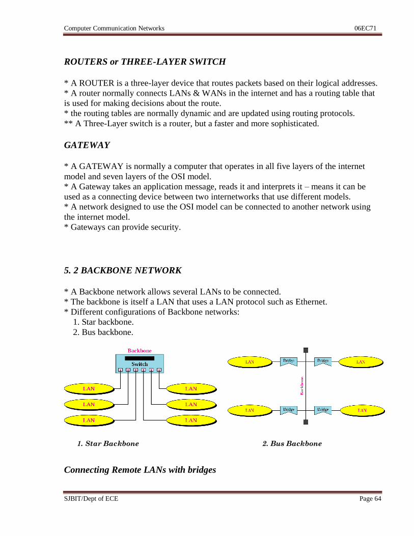
5. 2 BACKBONE NETWORK
* A Backbone network allows several LANs to be connected.
* The backbone is itself a LAN that uses a LAN protocol such as Ethernet.
* Different configurations of Backbone networks:
1. Star backbone.
2. Bus backbone.
Connecting Remote LANs with bridges
1. Star Backbone 2. Bus Backbone
Computer Communication Networks 06EC71
SJBIT/Dept of ECE Page 65
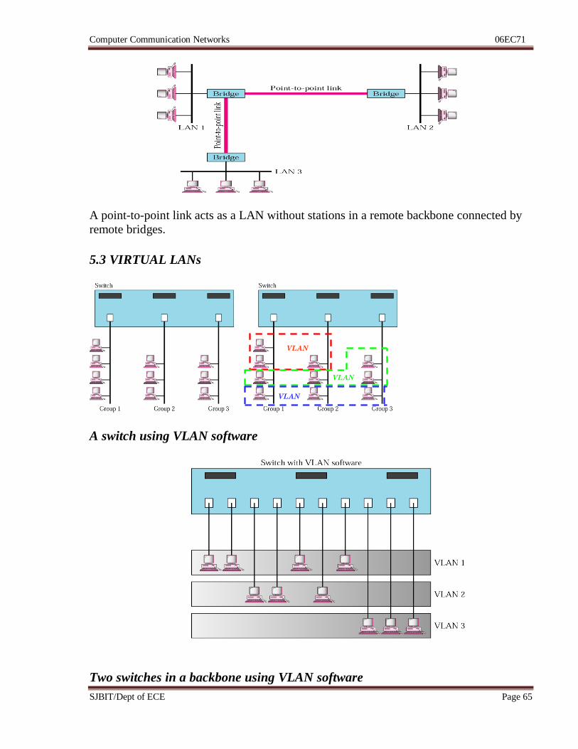
A point-to-point link acts as a LAN without stations in a remote backbone connected by
remote bridges.
5.3 VIRTUAL LANs
A switch using VLAN software
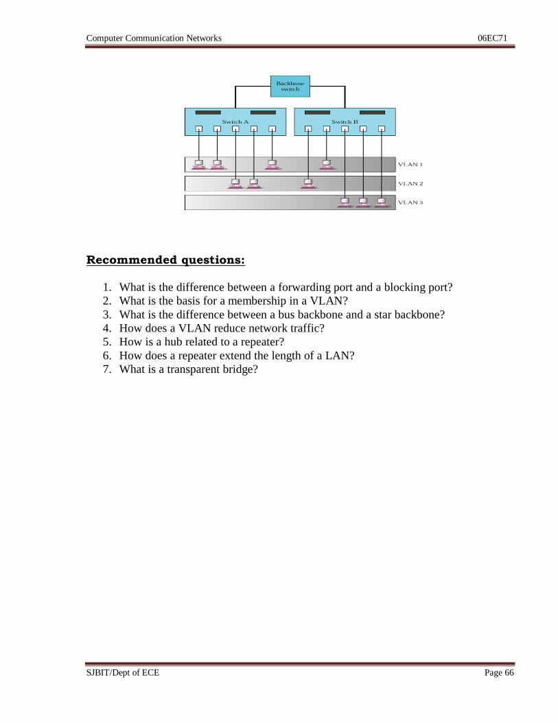
Two switches in a backbone using VLAN software
VLAN
1
VLAN
2
VLAN
3
Computer Communication Networks 06EC71
SJBIT/Dept of ECE Page 66
Recommended questions:
1. What is the difference between a forwarding port and a blocking port?
2. What is the basis for a membership in a VLAN?
3. What is the difference between a bus backbone and a star backbone?
4. How does a VLAN reduce network traffic?
5. How is a hub related to a repeater?
6. How does a repeater extend the length of a LAN?
7. What is a transparent bridge?
Computer Communication Networks 06EC71
SJBIT/Dept of ECE Page 67
Unit 6: Hrs: 07
Syllabus:
Network layer, Logical addressing, IPv4 addresses, IPv6 addresses, IPv4 and IPv6
transition from IPv4 to IPv6.
Recommended readings:
Text Book: Data Communication & Networking, B Forouzan, 4e, TMH
Chapter 19 – page 549 to 572
Chapter 20 – page 582 to 605
Computer Communication Networks 06EC71
SJBIT/Dept of ECE Page 68
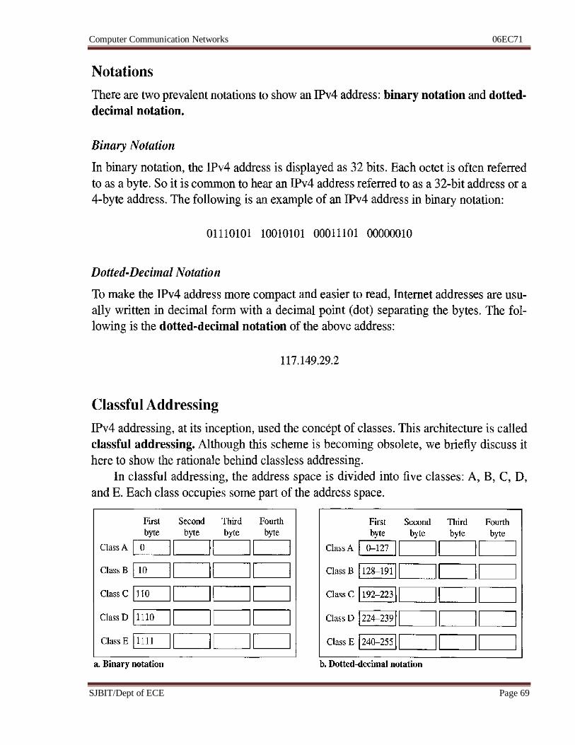
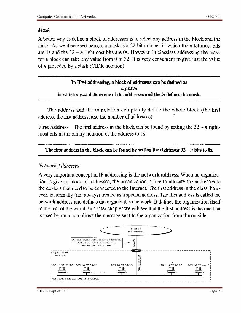
6.1 IPv4 Addresses
Computer Communication Networks 06EC71
SJBIT/Dept of ECE Page 69
Computer Communication Networks 06EC71
SJBIT/Dept of ECE Page 70
Computer Communication Networks 06EC71
SJBIT/Dept of ECE Page 71
Computer Communication Networks 06EC71
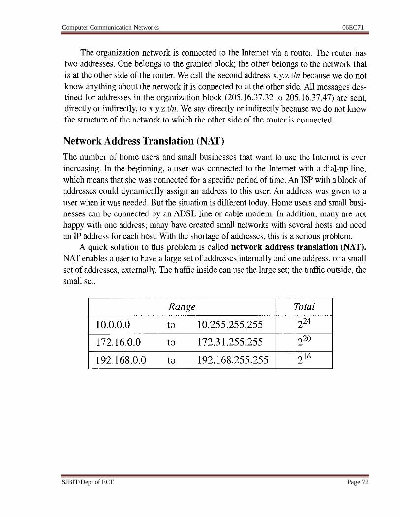
SJBIT/Dept of ECE Page 72
Computer Communication Networks 06EC71
SJBIT/Dept of ECE Page 73
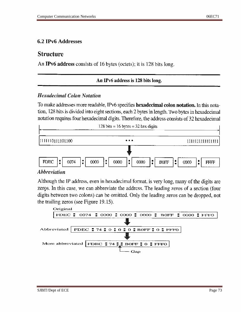
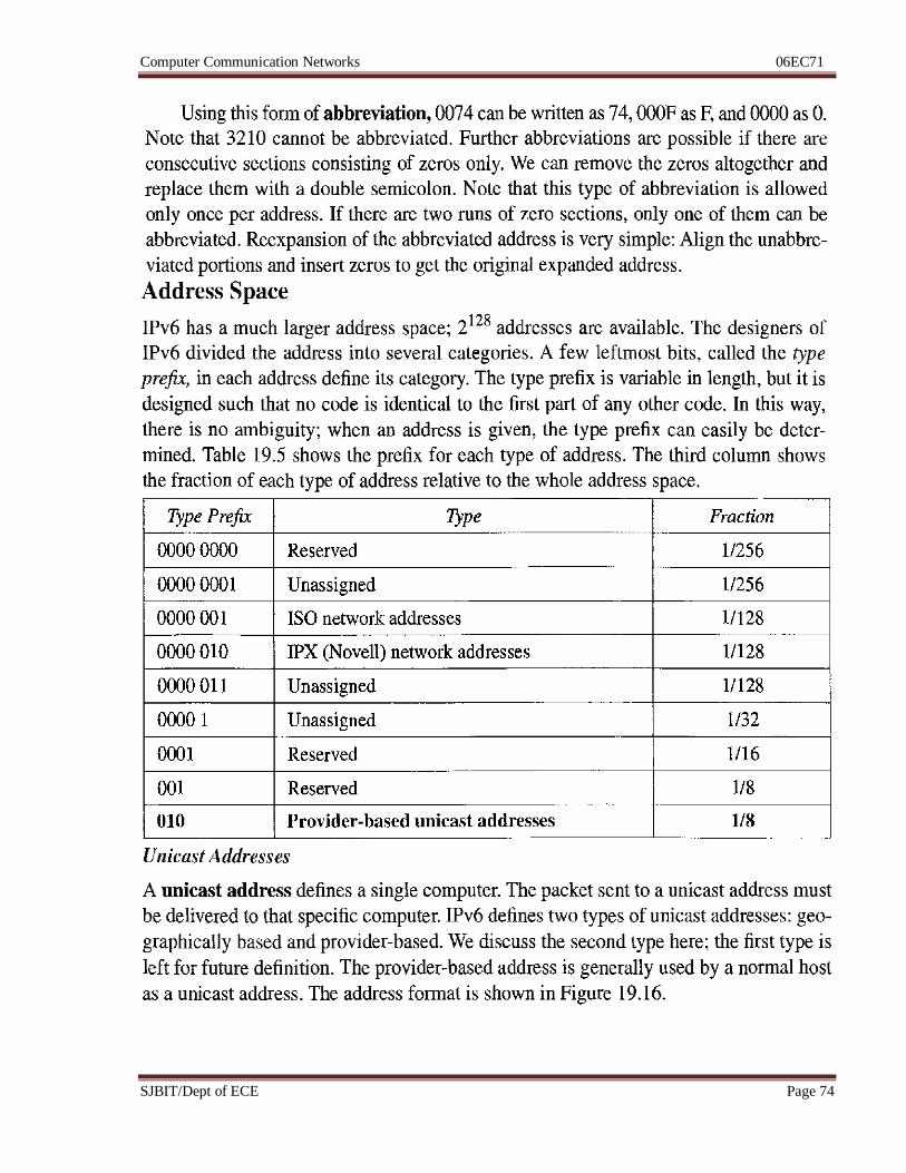
6.2 IPv6 Addresses
Computer Communication Networks 06EC71
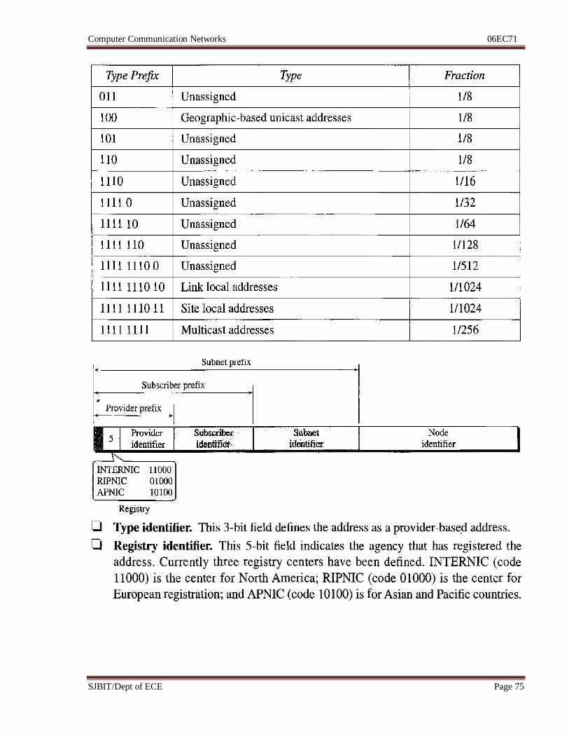
SJBIT/Dept of ECE Page 74
Computer Communication Networks 06EC71
SJBIT/Dept of ECE Page 75
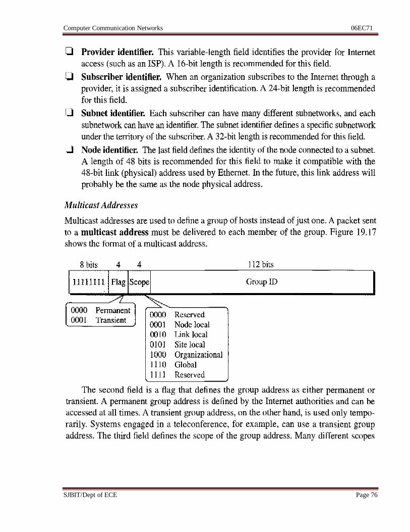
Computer Communication Networks 06EC71
SJBIT/Dept of ECE Page 76
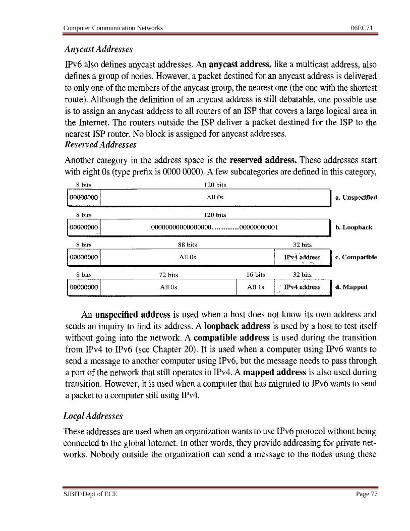
Computer Communication Networks 06EC71
SJBIT/Dept of ECE Page 77
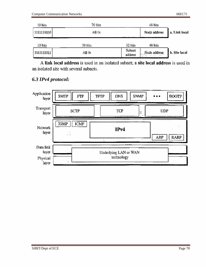
Computer Communication Networks 06EC71
SJBIT/Dept of ECE Page 78
6.3 IPv4 protocol:
Computer Communication Networks 06EC71
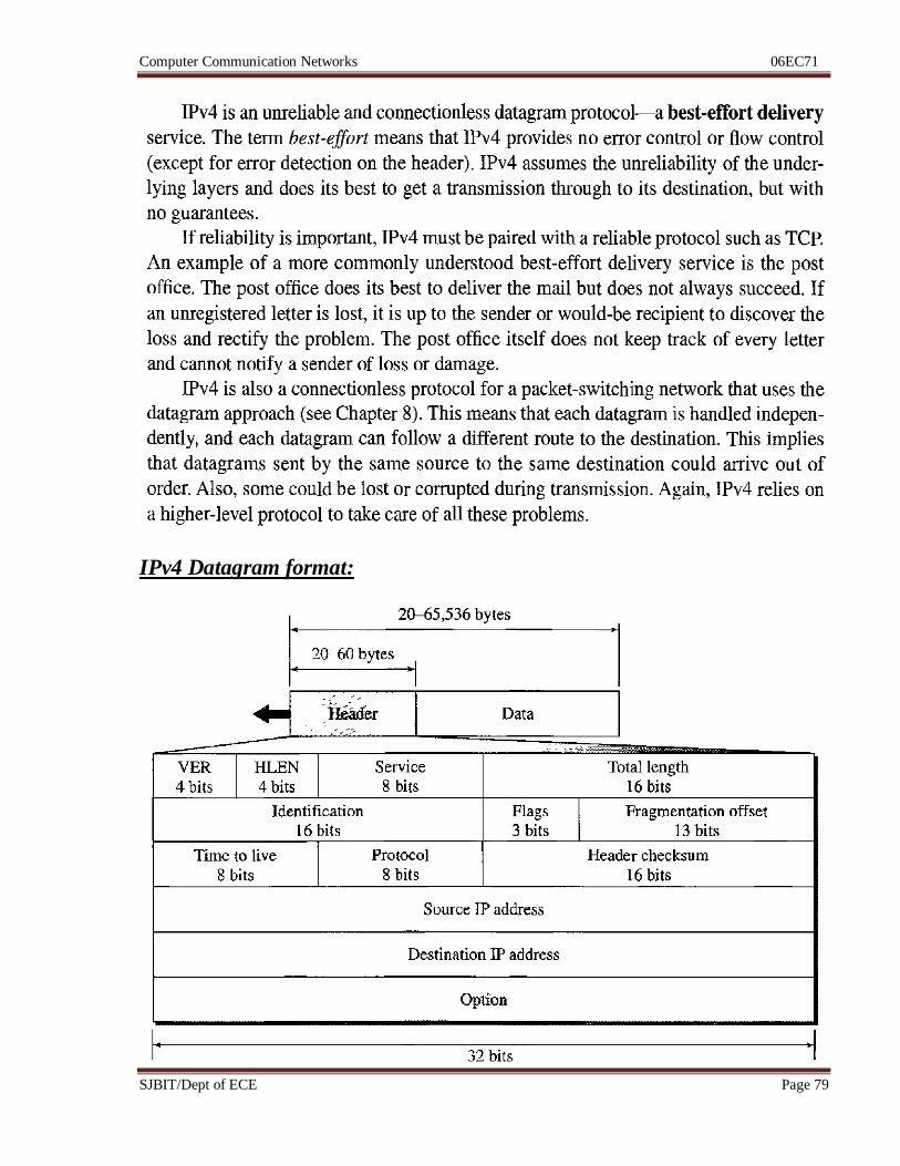
SJBIT/Dept of ECE Page 79
IPv4 Datagram format:
Computer Communication Networks 06EC71
SJBIT/Dept of ECE Page 80
Computer Communication Networks 06EC71
SJBIT/Dept of ECE Page 81
Computer Communication Networks 06EC71
SJBIT/Dept of ECE Page 82
Computer Communication Networks 06EC71
SJBIT/Dept of ECE Page 83
Computer Communication Networks 06EC71
SJBIT/Dept of ECE Page 84
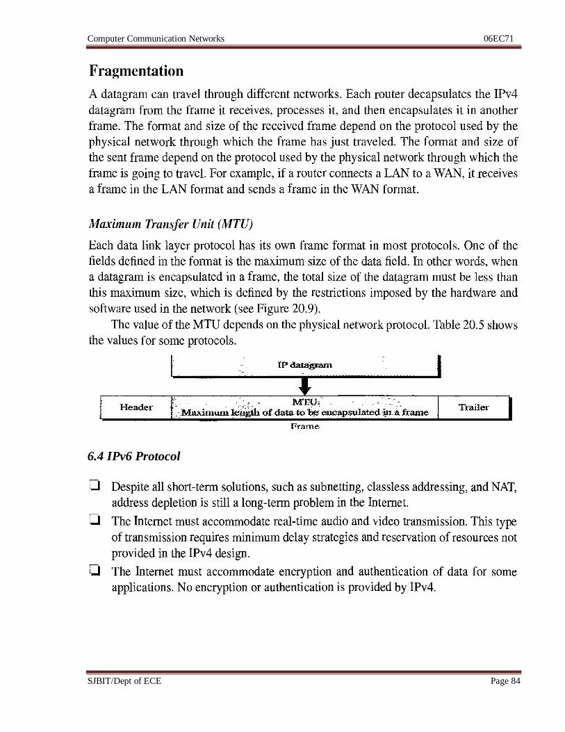
6.4 IPv6 Protocol
Computer Communication Networks 06EC71
SJBIT/Dept of ECE Page 85
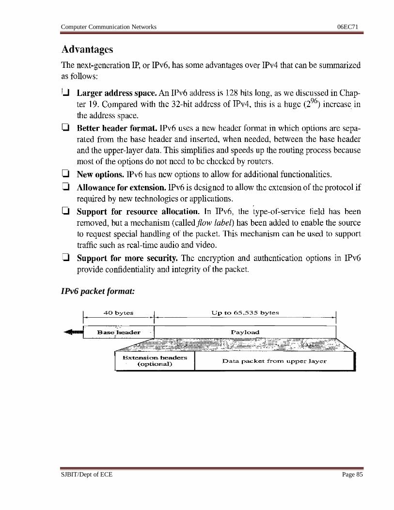
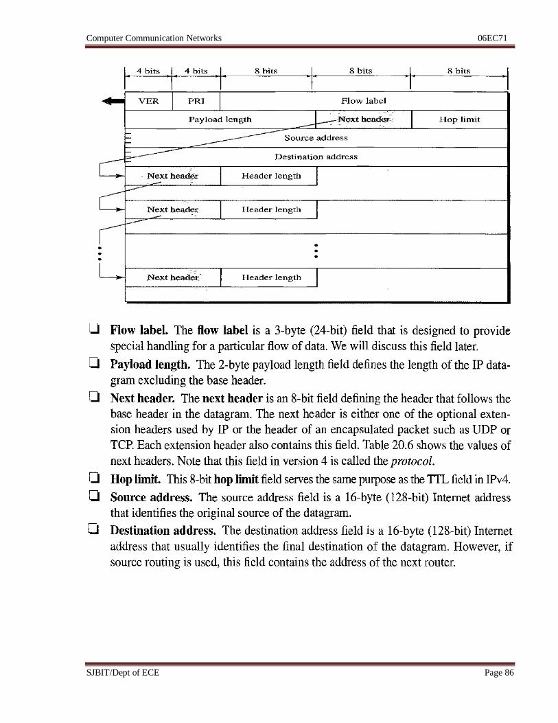
IPv6 packet format:
Computer Communication Networks 06EC71
SJBIT/Dept of ECE Page 86
Computer Communication Networks 06EC71
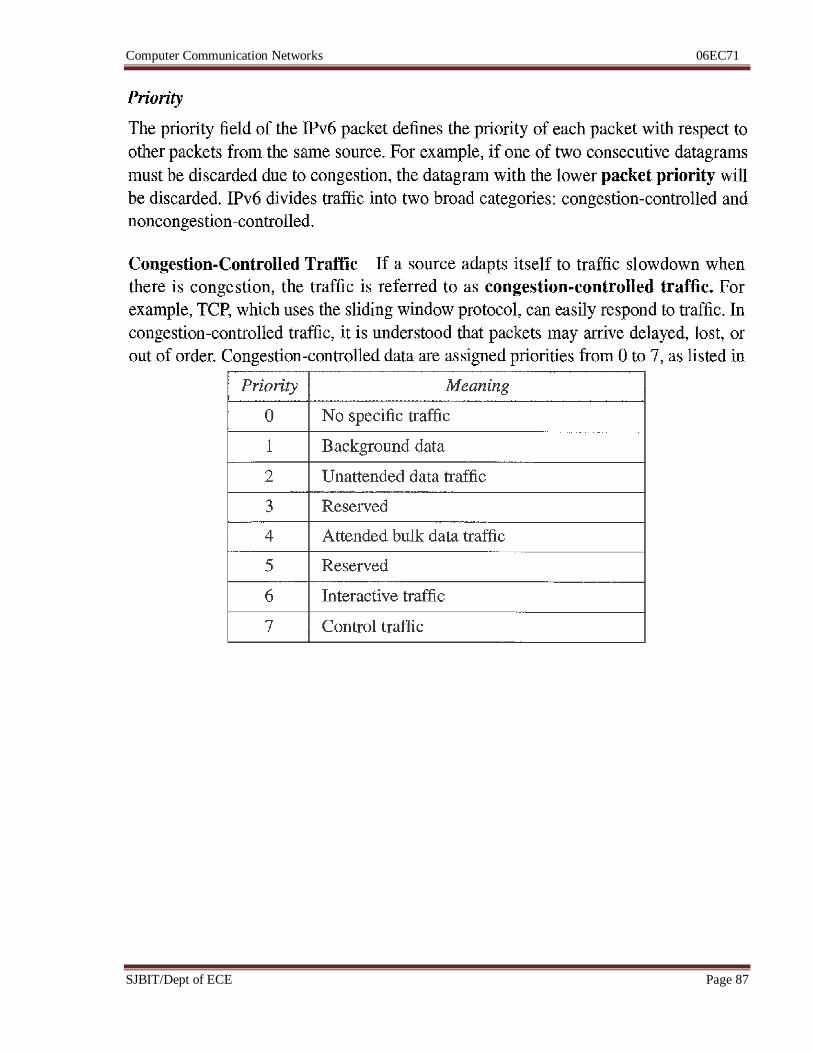
SJBIT/Dept of ECE Page 87
Computer Communication Networks 06EC71
SJBIT/Dept of ECE Page 88
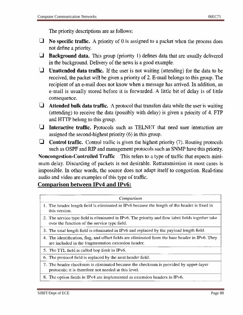
Comparison between IPv4 and IPv6:
Computer Communication Networks 06EC71
SJBIT/Dept of ECE Page 89
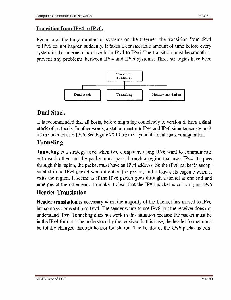
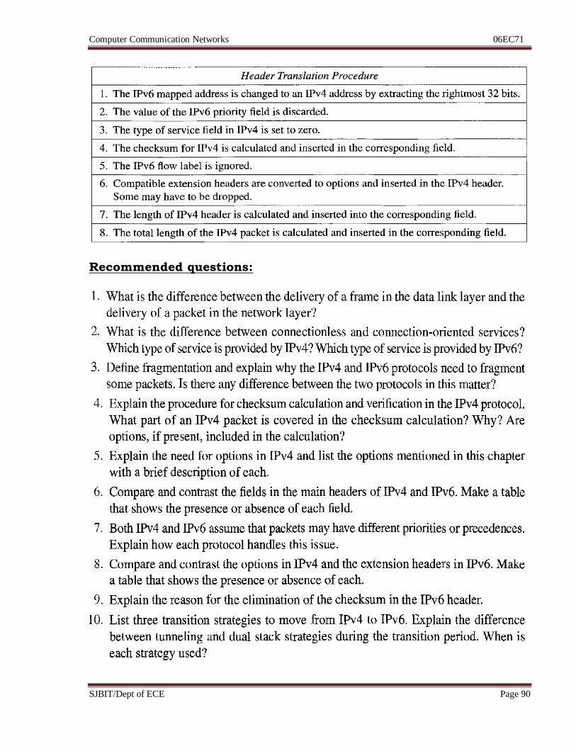
Transition from IPv4 to IPv6:
Computer Communication Networks 06EC71
SJBIT/Dept of ECE Page 90
Recommended questions:

Computer Communication Networks 06EC71
SJBIT/Dept of ECE Page 91
Unit 7: Hrs: 06
Syllabus:
Delivery, Forwarding, Unicast Routing protocols, Multicast Routing protocols
Recommended readings:
Text Book: Data Communication & Networking, B Forouzan, 4e, TMH
Chapter 22: Page 647 to 697
Computer Communication Networks 06EC71
SJBIT/Dept of ECE Page 92
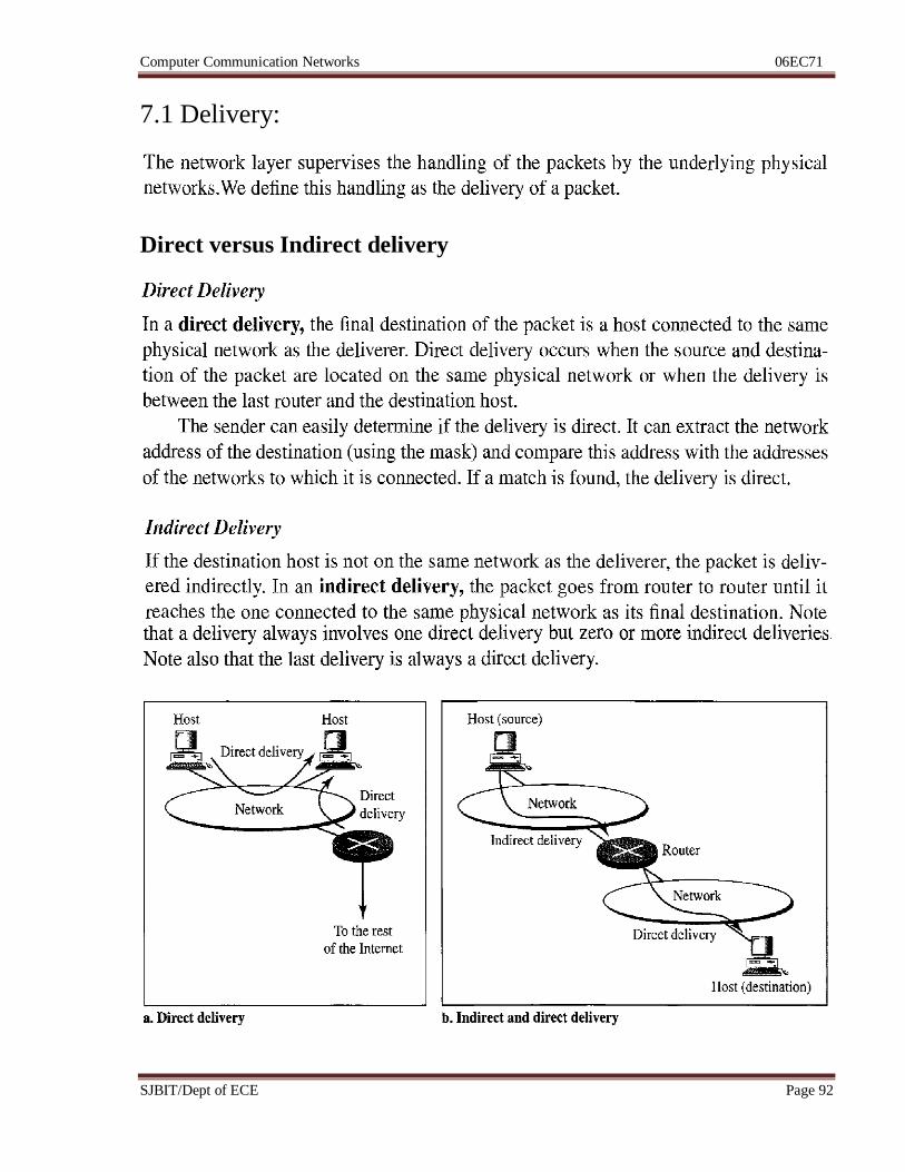
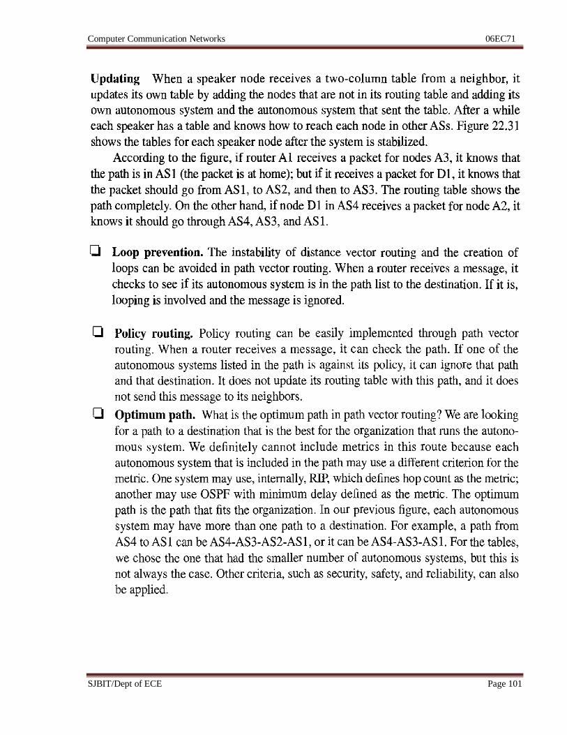
7.1 Delivery:
Direct versus Indirect delivery
Computer Communication Networks 06EC71
SJBIT/Dept of ECE Page 93
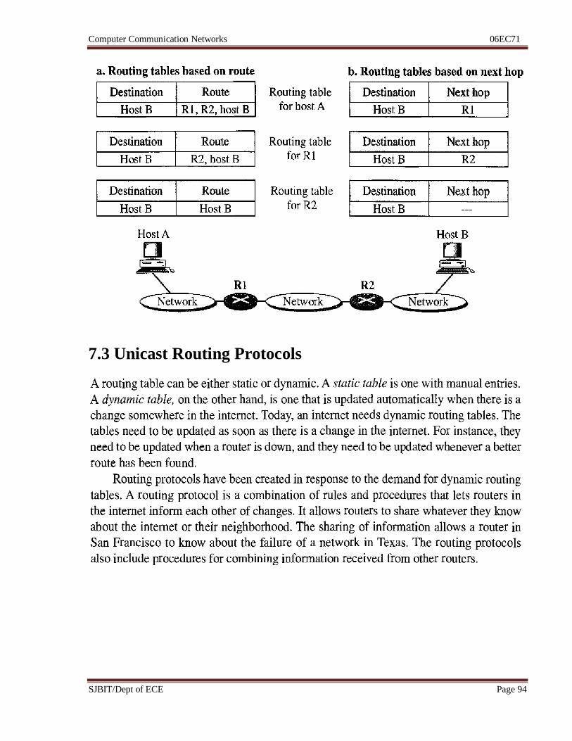
7.2 Forwarding:
Computer Communication Networks 06EC71
SJBIT/Dept of ECE Page 94
7.3 Unicast Routing Protocols
Computer Communication Networks 06EC71
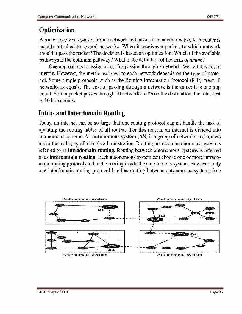
SJBIT/Dept of ECE Page 95
Computer Communication Networks 06EC71
SJBIT/Dept of ECE Page 96
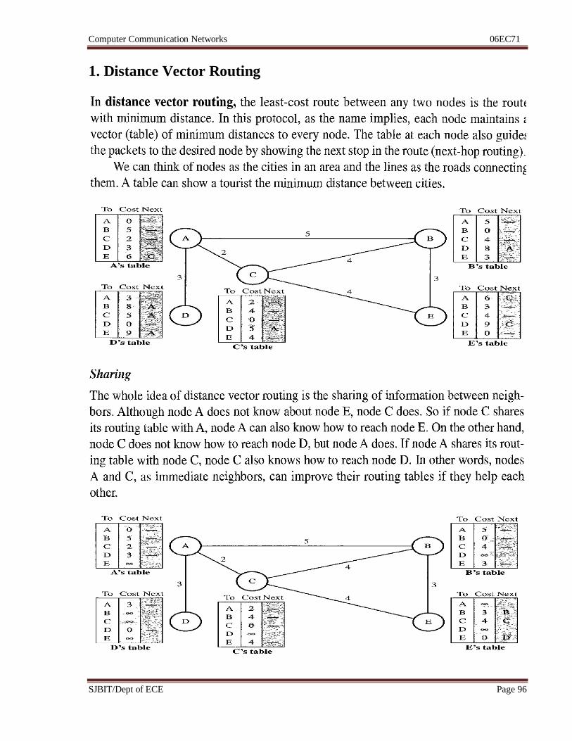
1. Distance Vector Routing
Computer Communication Networks 06EC71
SJBIT/Dept of ECE Page 97
Computer Communication Networks 06EC71
SJBIT/Dept of ECE Page 98
2. Routing Information Protocol (RIP)
Computer Communication Networks 06EC71
SJBIT/Dept of ECE Page 99
4. Path Vector Routing
Computer Communication Networks 06EC71
SJBIT/Dept of ECE Page 100
Computer Communication Networks 06EC71
SJBIT/Dept of ECE Page 101
Computer Communication Networks 06EC71
SJBIT/Dept of ECE Page 102
7.4 Multicast Routing Protocols
Computer Communication Networks 06EC71
SJBIT/Dept of ECE Page 103
Recommended questions:

Computer Communication Networks 06EC71
SJBIT/Dept of ECE Page 104
Unit 8: Hrs: 06
Syllabus:
Transport layer process to process delivery, UDP, TCP, Domain name system,
Resolution.
Recommended readings:
Text Book: Data Communication & Networking, B Forouzan, 4e, TMH
Chapter 23 – page 703 to 753
Computer Communication Networks 06EC71
SJBIT/Dept of ECE Page 105
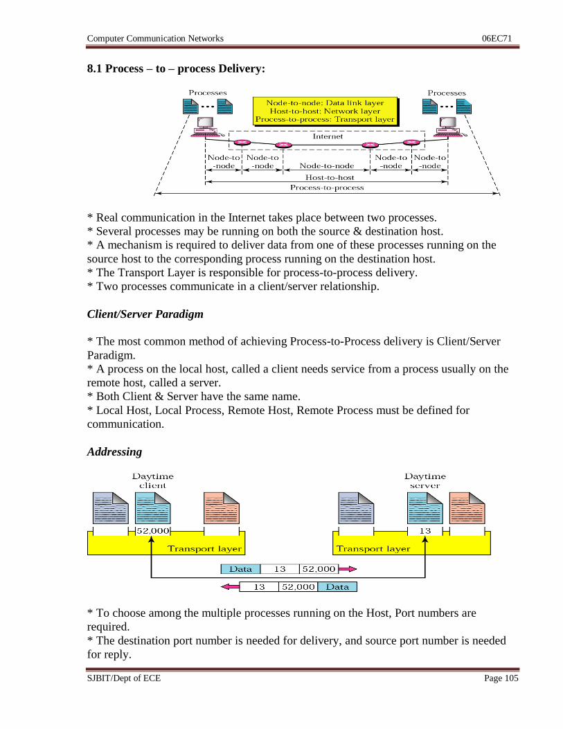
8.1 Process – to – process Delivery:
* Real communication in the Internet takes place between two processes.
* Several processes may be running on both the source & destination host.
* A mechanism is required to deliver data from one of these processes running on the
source host to the corresponding process running on the destination host.
* The Transport Layer is responsible for process-to-process delivery.
* Two processes communicate in a client/server relationship.
Client/Server Paradigm
* The most common method of achieving Process-to-Process delivery is Client/Server
Paradigm.
* A process on the local host, called a client needs service from a process usually on the
remote host, called a server.
* Both Client & Server have the same name.
* Local Host, Local Process, Remote Host, Remote Process must be defined for
communication.
Addressing
* To choose among the multiple processes running on the Host, Port numbers are
required.
* The destination port number is needed for delivery, and source port number is needed
for reply.
Computer Communication Networks 06EC71
SJBIT/Dept of ECE Page 106
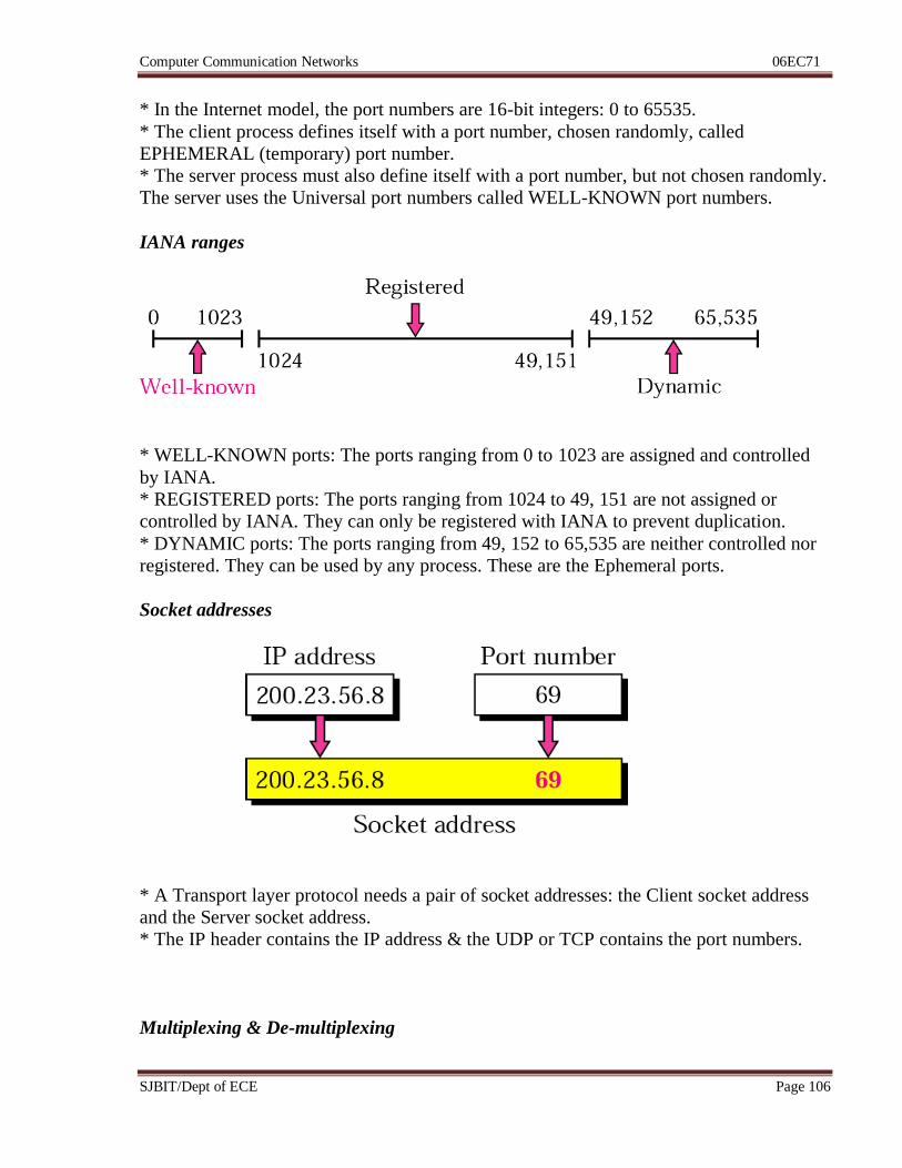
* In the Internet model, the port numbers are 16-bit integers: 0 to 65535.
* The client process defines itself with a port number, chosen randomly, called
EPHEMERAL (temporary) port number.
* The server process must also define itself with a port number, but not chosen randomly.
The server uses the Universal port numbers called WELL-KNOWN port numbers.
IANA ranges
* WELL-KNOWN ports: The ports ranging from 0 to 1023 are assigned and controlled
by IANA.
* REGISTERED ports: The ports ranging from 1024 to 49, 151 are not assigned or
controlled by IANA. They can only be registered with IANA to prevent duplication.
* DYNAMIC ports: The ports ranging from 49, 152 to 65,535 are neither controlled nor
registered. They can be used by any process. These are the Ephemeral ports.
Socket addresses
* A Transport layer protocol needs a pair of socket addresses: the Client socket address
and the Server socket address.
* The IP header contains the IP address & the UDP or TCP contains the port numbers.
Multiplexing & De-multiplexing
Computer Communication Networks 06EC71
SJBIT/Dept of ECE Page 107
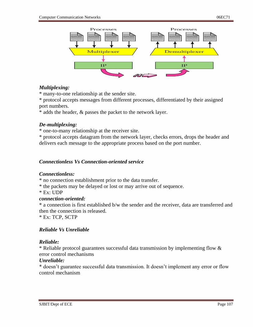
Multiplexing:
* many-to-one relationship at the sender site.
* protocol accepts messages from different processes, differentiated by their assigned
port numbers.
* adds the header, & passes the packet to the network layer.
De-multiplexing:
* one-to-many relationship at the receiver site.
* protocol accepts datagram from the network layer, checks errors, drops the header and
delivers each message to the appropriate process based on the port number.
Connectionless Vs Connection-oriented service
Connectionless:
* no connection establishment prior to the data transfer.
* the packets may be delayed or lost or may arrive out of sequence.
* Ex: UDP
connection-oriented:
* a connection is first established b/w the sender and the receiver, data are transferred and
then the connection is released.
* Ex: TCP, SCTP
Reliable Vs Unreliable
Reliable:
* Reliable protocol guarantees successful data transmission by implementing flow &
error control mechanisms
Unreliable:
* doesn’t guarantee successful data transmission. It doesn’t implement any error or flow
control mechanism

Computer Communication Networks 06EC71
SJBIT/Dept of ECE Page 108
USER DATAGRAM PROTOCOL (UDP)
* Is called a connectionless, unreliable transport protocol.
* it doesn’t add anything to the services of IP except to provide process-to-process
communication instead of host-to-host communication.
* it performs very limited error checking.
* if a process wants to send a small message and doesn’t care much about reliability, it
can use UDP.
WELL-KNOWN port numbers for UDP
Port Protocol Description
7 Echo Echoes a received datagram back to the sender
9 Discard Discards any datagram that is received
11 Users Active users
13 Daytime Returns the date and the time
17 Quote Returns a quote of the day
19 Chargen Returns a string of characters
53 Nameserver Domain Name Service
67 Bootps Server port to download bootstrap information
68 Bootpc Client port to download bootstrap information
69 TFTP Trivial File Transfer Protocol
111 RPC Remote Procedure Call
123 NTP Network Time Protocol
161 SNMP Simple Network Management Protocol
162 SNMP Simple Network Management Protocol (trap)
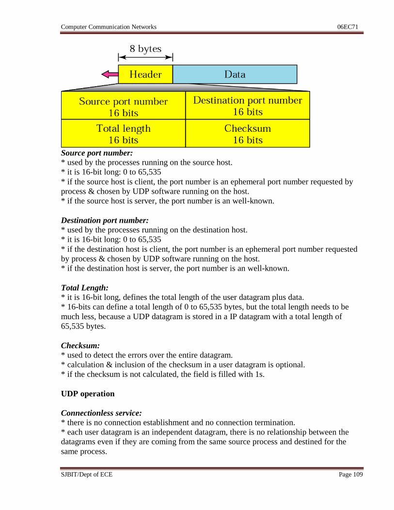
User Datagram format
* UDP packets, called user datagrams have a fixed-size header of 8 bytes.
Computer Communication Networks 06EC71
SJBIT/Dept of ECE Page 109
Source port number:
* used by the processes running on the source host.
* it is 16-bit long: 0 to 65,535
* if the source host is client, the port number is an ephemeral port number requested by
process & chosen by UDP software running on the host.
* if the source host is server, the port number is an well-known.
Destination port number:
* used by the processes running on the destination host.
* it is 16-bit long: 0 to 65,535
* if the destination host is client, the port number is an ephemeral port number requested
by process & chosen by UDP software running on the host.
* if the destination host is server, the port number is an well-known.
Total Length:
* it is 16-bit long, defines the total length of the user datagram plus data.
* 16-bits can define a total length of 0 to 65,535 bytes, but the total length needs to be
much less, because a UDP datagram is stored in a IP datagram with a total length of
65,535 bytes.
Checksum:
* used to detect the errors over the entire datagram.
* calculation & inclusion of the checksum in a user datagram is optional.
* if the checksum is not calculated, the field is filled with 1s.
UDP operation
Connectionless service:
* there is no connection establishment and no connection termination.
* each user datagram is an independent datagram, there is no relationship between the
datagrams even if they are coming from the same source process and destined for the
same process.
Computer Communication Networks 06EC71
SJBIT/Dept of ECE Page 110
* this means that user datagrams can travel on different paths.
* the user datagrams are not numbered
Flow and Error control:
* UDP is very simple, unreliable transport protocol.
* there is no Flow & Error control.
* lack of flow control & error control means that the process using UDP should provide
these mechanisms.
Encapsulation & Decapsulation:
* to send message from one process to another, the UDP protocol encapsulates and
decapsulates messages in an IP datagram.
Queuing
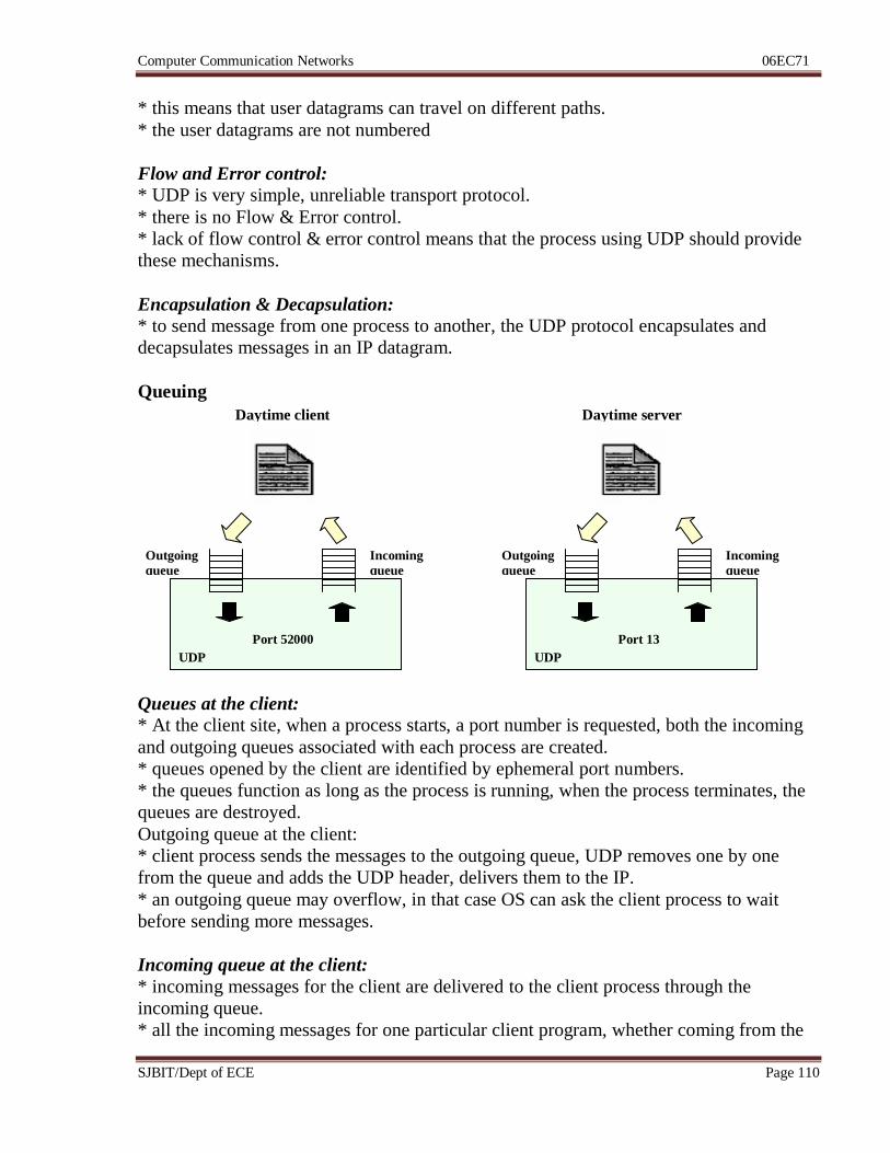
Queues at the client:
* At the client site, when a process starts, a port number is requested, both the incoming
and outgoing queues associated with each process are created.
* queues opened by the client are identified by ephemeral port numbers.
* the queues function as long as the process is running, when the process terminates, the
queues are destroyed.
Outgoing queue at the client:
* client process sends the messages to the outgoing queue, UDP removes one by one
from the queue and adds the UDP header, delivers them to the IP.
* an outgoing queue may overflow, in that case OS can ask the client process to wait
before sending more messages.
Incoming queue at the client:
* incoming messages for the client are delivered to the client process through the
incoming queue.
* all the incoming messages for one particular client program, whether coming from the
Outgoing
queue
Incoming
queue
Port 52000
UDP
Outgoing
queue
Incoming
queue
Port 13
UDP
Daytime client Daytime server
Computer Communication Networks 06EC71
SJBIT/Dept of ECE Page 111
same or a different server, are sent to the same queue.
* if there is no such incoming queue, the user datagrams are discarded and notified to the
server by sending a port unreachable message.
* an incoming queue can overflow, in that case the UDP drops the user datagram and
asks for a port unreachable message to be sent to the server.
Queues at server:
* at the server site, a server asks for incoming and outgoing queues using its well-known
port number, when it starts running.
* the queues remain open as long as the server process is running.
Incoming queue: * when a message arrives for a server, UDP sends the received user datagram to the end
of the incoming queue.
* all the incoming messages for one particular server process, whether coming from the
same or a different client, are sent to the same queue.
* if there is no such queue, UDP discards the user datagram and asks ICMP to send a port
unreachable message to the client.
* an incoming queue can overflow, in case, the UDP drops the user datagram and sends
the port unreachable message to the client.
Outgoing queue at the server:
* when a server wants to respond to a client, it sends messages to the outgoing queue.
* UDP removes one by one and, after adding the UDP header, delivers them to IP.
* an outgoing queue can overflow, in that case, the OS asks the server to wait before
sending any more messages.
Use of UDP
* UDP is suitable for a process that requires simple request-response communication with
little concern for flow and error control.
* UDP is suitable for a process with internal flow and error control mechanisms. Ex. –
TFTP.
* It is a suitable transport protocol for multicasting.
* UDP is used for management processes such as SNMP.
* UDP is used for some route updating protocols such as Routing Information Protocol
(RIP).
TRANSMISSION CONTROL PROTOCOL
* TCP is a connection-oriented, reliable transport protocol.
* it adds connection-oriented and reliability features to the services of IP.
Computer Communication Networks 06EC71
SJBIT/Dept of ECE Page 112
TCP services:
i) Process –to –process communication:
* TCP provides process-to-process communication using the port numbers.
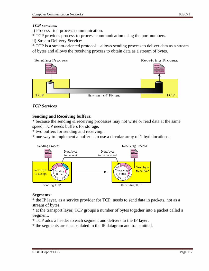
ii) Stream Delivery Service:
* TCP is a stream-oriented protocol – allows sending process to deliver data as a stream
of bytes and allows the receiving process to obtain data as a stream of bytes.
TCP Services
Sending and Receiving buffers:
* because the sending & receiving processes may not write or read data at the same
speed, TCP needs buffers for storage.
* two buffers for sending and receiving.
* one way to implement a buffer is to use a circular array of 1-byte locations.
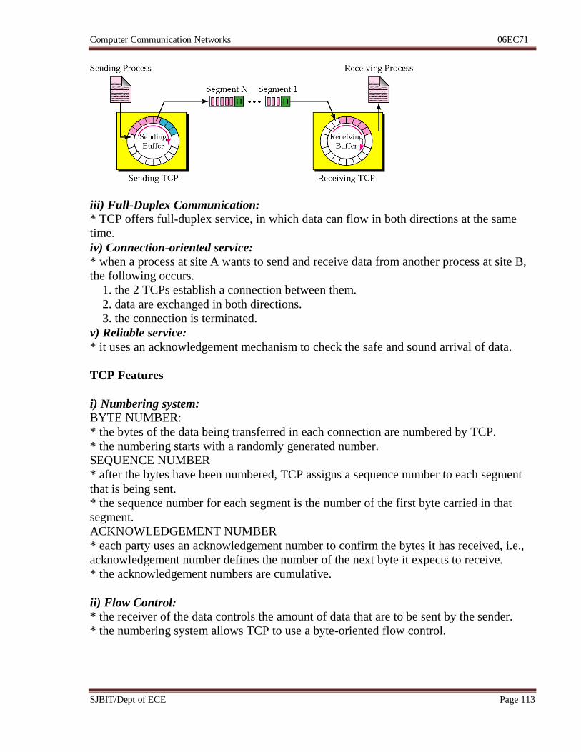
Segments:
* the IP layer, as a service provider for TCP, needs to send data in packets, not as a
stream of bytes.
* at the transport layer, TCP groups a number of bytes together into a packet called a
Segment.
* TCP adds a header to each segment and delivers to the IP layer.
* the segments are encapsulated in the IP datagram and transmitted.
Computer Communication Networks 06EC71
SJBIT/Dept of ECE Page 113
iii) Full-Duplex Communication:
* TCP offers full-duplex service, in which data can flow in both directions at the same
time.
iv) Connection-oriented service:
* when a process at site A wants to send and receive data from another process at site B,
the following occurs.
1. the 2 TCPs establish a connection between them.
2. data are exchanged in both directions.
3. the connection is terminated.
v) Reliable service:
* it uses an acknowledgement mechanism to check the safe and sound arrival of data.
TCP Features
i) Numbering system: BYTE NUMBER:
* the bytes of the data being transferred in each connection are numbered by TCP.
* the numbering starts with a randomly generated number.
SEQUENCE NUMBER
* after the bytes have been numbered, TCP assigns a sequence number to each segment
that is being sent.
* the sequence number for each segment is the number of the first byte carried in that
segment.
ACKNOWLEDGEMENT NUMBER
* each party uses an acknowledgement number to confirm the bytes it has received, i.e.,
acknowledgement number defines the number of the next byte it expects to receive.
* the acknowledgement numbers are cumulative.
ii) Flow Control: * the receiver of the data controls the amount of data that are to be sent by the sender.
* the numbering system allows TCP to use a byte-oriented flow control.
Computer Communication Networks 06EC71
SJBIT/Dept of ECE Page 114
iii) Error Control:
* to provide reliable service, TCP implements an error control mechanism.
iv) Congestion Control: * the amount of data sent by a sender is not only controlled by the receiver, but is also
determined by the level of congestion in the network.
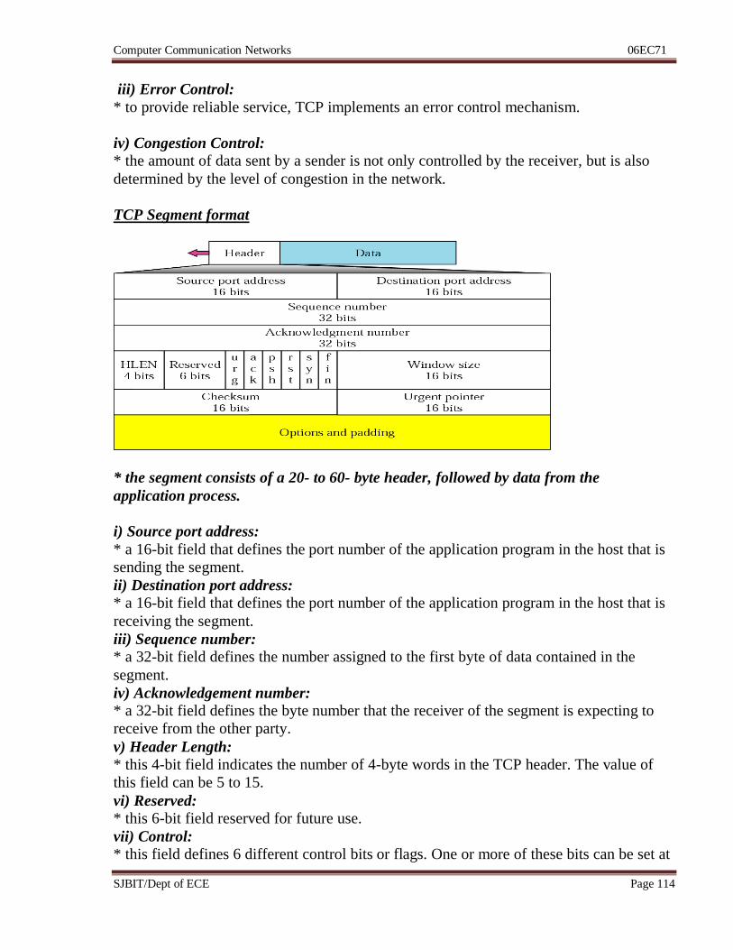
TCP Segment format
* the segment consists of a 20- to 60- byte header, followed by data from the
application process.
i) Source port address:
* a 16-bit field that defines the port number of the application program in the host that is
sending the segment.
ii) Destination port address:
* a 16-bit field that defines the port number of the application program in the host that is
receiving the segment.
iii) Sequence number:
* a 32-bit field defines the number assigned to the first byte of data contained in the
segment.
iv) Acknowledgement number:
* a 32-bit field defines the byte number that the receiver of the segment is expecting to
receive from the other party.
v) Header Length:
* this 4-bit field indicates the number of 4-byte words in the TCP header. The value of
this field can be 5 to 15.
vi) Reserved:
* this 6-bit field reserved for future use.
vii) Control:
* this field defines 6 different control bits or flags. One or more of these bits can be set at
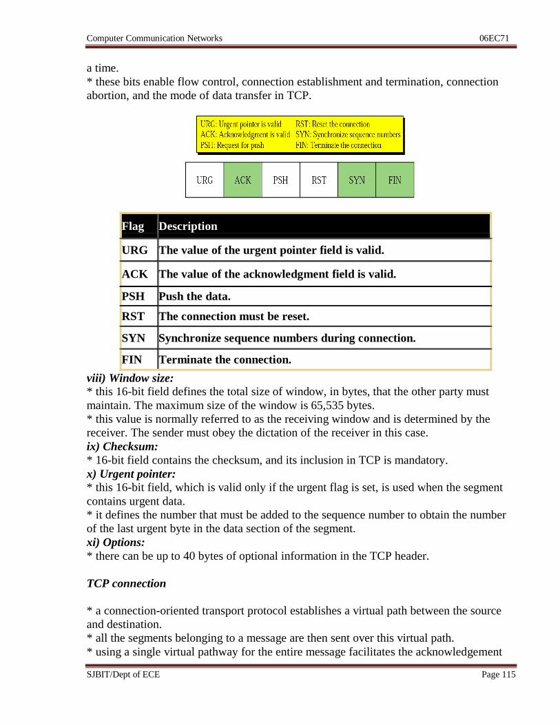
Computer Communication Networks 06EC71
SJBIT/Dept of ECE Page 115
a time.
* these bits enable flow control, connection establishment and termination, connection
abortion, and the mode of data transfer in TCP.
Flag Description
URG The value of the urgent pointer field is valid.
ACK The value of the acknowledgment field is valid.
PSH Push the data.
RST The connection must be reset.
SYN Synchronize sequence numbers during connection.
FIN Terminate the connection.
viii) Window size:
* this 16-bit field defines the total size of window, in bytes, that the other party must
maintain. The maximum size of the window is 65,535 bytes.
* this value is normally referred to as the receiving window and is determined by the
receiver. The sender must obey the dictation of the receiver in this case.
ix) Checksum:
* 16-bit field contains the checksum, and its inclusion in TCP is mandatory.
x) Urgent pointer:
* this 16-bit field, which is valid only if the urgent flag is set, is used when the segment
contains urgent data.
* it defines the number that must be added to the sequence number to obtain the number
of the last urgent byte in the data section of the segment.
xi) Options:
* there can be up to 40 bytes of optional information in the TCP header.
TCP connection
* a connection-oriented transport protocol establishes a virtual path between the source
and destination.
* all the segments belonging to a message are then sent over this virtual path.
* using a single virtual pathway for the entire message facilitates the acknowledgement
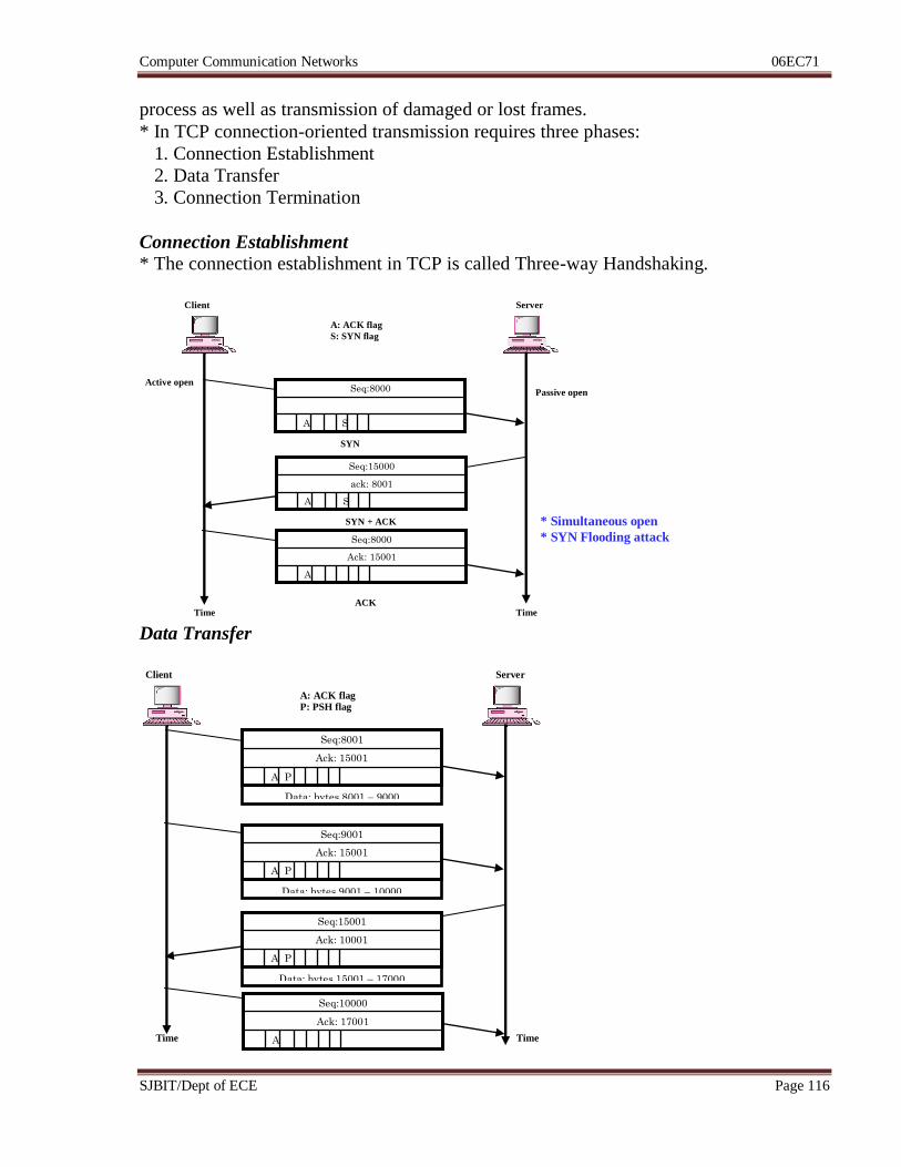
Computer Communication Networks 06EC71
SJBIT/Dept of ECE Page 116
process as well as transmission of damaged or lost frames.
* In TCP connection-oriented transmission requires three phases:
1. Connection Establishment
2. Data Transfer
3. Connection Termination
Connection Establishment
* The connection establishment in TCP is called Three-way Handshaking.
Data Transfer
A
Ack: 15001
Seq:8000
A S
ack: 8001
Seq:15000
A S
Seq:8000
A: ACK flag
S: SYN flag
Active open Passive open
SYN
SYN + ACK
ACK Time Time
Client Server
* Simultaneous open
* SYN Flooding attack
A P
Ack: 15001
Seq:8001
A: ACK flag P: PSH flag
Time Time
Client Server
Data: bytes 8001 – 9000
A P
Ack: 15001
Seq:9001
Data: bytes 9001 – 10000
A P
Ack: 10001
Seq:15001
Data: bytes 15001 – 17000
A
Ack: 17001
Seq:10000
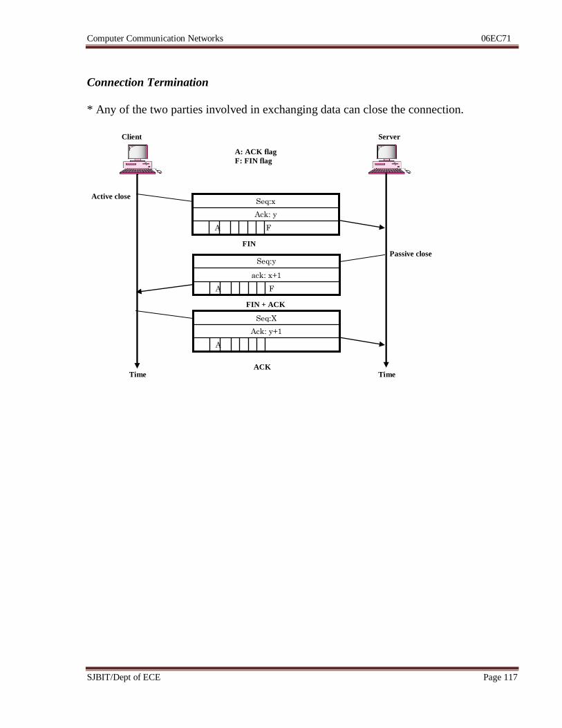
Computer Communication Networks 06EC71
SJBIT/Dept of ECE Page 117
Connection Termination
* Any of the two parties involved in exchanging data can close the connection.
A
Ack: y+1
Seq:X
A F
ack: x+1
Seq:y
A F
Ack: y
Seq:x
A: ACK flag
F: FIN flag
Active close
Passive close
FIN
FIN + ACK
ACK Time Time
Client Server
Computer Communication Networks 06EC71
SJBIT/Dept of ECE Page 118
Recommended questions:


![Ece Vii Optical Fiber Communication [06ec72] Notes](https://img.pdfslide.us/doc/110x75/5531e4984a7959372c8b4b9b/ece-vii-optical-fiber-communication-06ec72-notes.jpg)
![ECE-V-DIGITAL SIGNAL PROCESSING [10EC52]-NOTES.pdf](https://img.pdfslide.us/doc/110x75/56d6cbe71a28ab30169caa7d/ece-v-digital-signal-processing-10ec52-notespdf.jpg)


![Ece Vii Real Time Systems [06ec762] Notes](https://img.pdfslide.us/doc/110x75/545df80ab0af9fb2208b45e7/ece-vii-real-time-systems-06ec762-notes.jpg)


![ECE-VII-POWER ELECTRONICS [10EC73]-NOTES.pdf](https://img.pdfslide.us/doc/110x75/577cc48b1a28aba71199a74d/ece-vii-power-electronics-10ec73-notespdf.jpg)

![ECE-VI-SATELLITE COMMUNICATIONS [10EC662]-NOTES.pdf](https://img.pdfslide.us/doc/110x75/55cf9b50550346d033a58eee/ece-vi-satellite-communications-10ec662-notespdf.jpg)


![ECE-VIII-WIRELESS COMMUNICATION [10EC81]-NOTES.pdf](https://img.pdfslide.us/doc/110x75/577c7ffe1a28abe054a6dc1f/ece-viii-wireless-communication-10ec81-notespdf.jpg)


![Ece Vii Image Processing [06ec756] Solution](https://img.pdfslide.us/doc/110x75/552bbb4a5503464c158b45a9/ece-vii-image-processing-06ec756-solution.jpg)