Embed Size (px)
Citation preview

ECE 661: Homework #3
September 18, 2012
Professor Kak
Albert Parra Pozo
Contents
Method Outline . . . . . . . . . . . . . . . . . . . . . . . . . . . . . . . . . . . . . . . . . . . . . . . 2
Two-Step Method . . . . . . . . . . . . . . . . . . . . . . . . . . . . . . . . . . . . . . . . . . . . . 2
Single-Step Method . . . . . . . . . . . . . . . . . . . . . . . . . . . . . . . . . . . . . . . . . . . . 4
Two-Step Method VS Single-Step Method . . . . . . . . . . . . . . . . . . . . . . . . . . . . . . . . 4
APPENDIX 1 - Original Images . . . . . . . . . . . . . . . . . . . . . . . . . . . . . . . . . . . . . 5
APPENDIX 2 - Two-Step Method . . . . . . . . . . . . . . . . . . . . . . . . . . . . . . . . . . . . 10
APPENDIX 3 - One-Step Method . . . . . . . . . . . . . . . . . . . . . . . . . . . . . . . . . . . . 21
APPENDIX 4 - Code . . . . . . . . . . . . . . . . . . . . . . . . . . . . . . . . . . . . . . . . . . . 29
1

Albert Parra Pozo ECE 661 (Professor Kak): Homework #3 Method Outline
Method Outline
The goal of this project is to eliminate both the projective and affine distortions in an image. This can
be accomplished using two different methods. The first one, from now on called “two-step method”, first
eliminates the projective distortion by taking the vanishing line present in the image plane back to infinity
(lV L → l∞). Then, the affine distortion is removed by using the constraint l′TC∗∞m′. The second one, from
now one called “single-step method”, removes the projective and affine distortions at the same time by using
the dual conic C∗∞ and five pairs of physically orthogonal lines.
Two-Step Method
In the two-step method we first remove the projective distortion by taking the vanishing line present in the
image plane back to infinity. For this purpose we use the homography:
Hp =
⎡⎣1 0 0
0 1 0
l1 l2 l3
⎤⎦ ,
where lV L = [l1, l2, l3]T is the vanishing line. To obtain lV L we take the corners of a rectangular frame
that suffers from projective distortion and form two sets of parallel lines in the world plane. Defining this
corner points as x1, x2, x3, x4 we find the sets of parallel lines by taking their cross-product pairwise, so that
l1 = x1 × x2
l2 = x3 × x4
l3 = x1 × x3
l4 = x2 × x4.
Therefore, the intersection of each set of parallel lines gives us two points belonging to lLV :
P = l1 × l2
Q = l3 × l4.
With this, we form the vanishing line:
lV L = P ×Q = [l1, l2, l3]T .
Once we have computed lV L, we can apply the homography Hp mentioned above to eliminate the pro-
jective distortion. Now the image plane only contains affine distortion, which can be removed knowing that
the angle between two lines l = [l1, l2, l3]T and m = [m1,m2,m3]
T in the image plane with affine distortion
satisfy:
cos(θ) =l1m1 + l2m2√
(l21 + l22)(m21 +m2
2)=
lTC∗∞m√
(lTC∗∞l)(mTC∗∞m),
Two-Step Method continued on next page. . . Page 2 of 42

Albert Parra Pozo ECE 661 (Professor Kak): Homework #3 Two-Step Method
where C∗∞ =
⎡⎣1 0 0
0 1 0
0 0 0
⎤⎦. Using the fact that C∗′
= HC∗HT we can rewrite the numerator as:
cos(θ)numerator = l′TC∗′
∞m′.
If we now assume that l and m are orthogonal (i.e., cos(θ) = cos(π2 ) = 0) the above expression becomes
l′TC∗′
∞m′= 0,
or
l′THaC
∗∞HT
a m′= 0,
where in this case Ha =
[A 0
0T 1
], corresponding to the affine transformation homography. Expanding
the expression above:
l′THaC
∗∞HT
a m′= [l′1, l
′2, l
′3]
[AAT 0
0T 0
]⎡⎣m
′1
m′2
m′3
⎤⎦ .
Defining S = AAT , and being therefore S a symmetric matrix S =
[s11 s12s12 s22
]we obtain the expression
s11l′1m
′1 + s12(l
′1m
′2 + l′2m
′1) + s22l
′2m
′2 = 0.
If we use two angle-to-angle correspondences between two lines forming a 90◦ angle in the original scene
we can solve for s11, s12 and s22. Note that we can use one of the corners from the lines used to remove the
projective distortion as the first set of orthogonal lines, but the second set cannot be parallel to the first,
because parallel lines only differ in the third component, and this is ignored on the system of equation above.
Also note that although we have three unknowns we only need to know them up to their ratios, so we really
only have two unknowns (by setting one of them to 1 - e.g. s22 = 1):
s11l′1m
′1 + s12(l
′1m
′2 + l′2m
′1) = −l′2m
′2.
Once we have S, we can use SVD to estimate A, taking advantage of A being positive definite:
A = UDUT
S = AAT = UDUTUDUT = UD2UT ,
and therefore Ha. To sum up, both the projective and affine distortions are eliminated by applying the
two-step homography H−1p Ha.
Single-Step Method continued on next page. . . Page 3 of 42

Albert Parra Pozo ECE 661 (Professor Kak): Homework #3 Single-Step Method
Single-Step Method
We can use a single step to get rid of both the projective and affine distortions simultaneously, by using the
dual conic C∗∞. The homography H can be expressed as
H =
[A 0
vT 1
],
and thus the dual conic in the image plane is
C∗′∞ = HC∗
∞HT =
[AAT Av
vTAT vT v
].
Knowing that the general form of C∗′∞ is
C∗′∞ =
⎡⎣ a b/2 d/2
b/2 c e/2
d/2 e/2 f
⎤⎦ ,
and also knowing that l′TC∗′
∞m′= 0 when l and m are orthogonal in the world plane, we end up with
the equation wT z = 0, where
w =
⎡⎢⎢⎢⎢⎢⎢⎢⎣
l1m1l1m2+l2m1
2
l2m2l1m3+l3m1
2l2m3+l3m2
2
l3m3
⎤⎥⎥⎥⎥⎥⎥⎥⎦, z =
⎡⎢⎢⎢⎢⎢⎢⎢⎣
a
b
c
d
e
f
⎤⎥⎥⎥⎥⎥⎥⎥⎦
Then, by using five pairs of physically orthogonal lines in the world plane we can find z (as we did for
s in the 2-step method above). A can be found, again, through an SVD decomposition, and v according to
the rest of the components in C∗′∞. With all these parameters we can build H and apply the homography to
the input image to correct both the projective and the affine distortion at once.
Two-Step Method VS Single-Step Method
On the one hand, although the single-step method is more straightforward than the two-step method, it
requires several attempts on the selection of the five pairs of orthogonal lines to provide an accurate results.
The single-step method, however, requires less lines and the experimental results reflect that the line selection
does not seem to be that strict. On the other hand, although the single-step algorithm is shorter (i.e., less
lines of code), it requires at least two SVD decompositions to create the homography matrix, while in the
two-step method only one SVD decomposition is necessary. Moreover, the first step in the two-step method
is quite straightforward (basically seven cross products). It is also worth mentioning that I do not see any
difference in execution time between the two methods, maybe because of the fact that neither of them
requires a large amount of memory. To sum up, and taking into account that the code can be improved for
both methods, I found the two-step method less problematic for testing purposes.
Page 4 of 42
Albert Parra Pozo ECE 661 (Professor Kak): Homework #3 APPENDIX 1 - Original Images
APPENDIX 1 - Original Images
Figure 1: adams1 - Original
Figure 2: adams2 - Original
APPENDIX 1 - Original Images continued on next page. . . Page 5 of 42

Albert Parra Pozo ECE 661 (Professor Kak): Homework #3 APPENDIX 1 - Original Images
Figure 3: board1 - Original
Figure 4: board2 - Original
APPENDIX 1 - Original Images continued on next page. . . Page 6 of 42

Albert Parra Pozo ECE 661 (Professor Kak): Homework #3 APPENDIX 1 - Original Images
Figure 5: door1 - Original
Figure 6: door2 - Original
APPENDIX 1 - Original Images continued on next page. . . Page 7 of 42

Albert Parra Pozo ECE 661 (Professor Kak): Homework #3 APPENDIX 1 - Original Images
Figure 7: tree1 - Original
Figure 8: tree2 - Original
APPENDIX 1 - Original Images continued on next page. . . Page 8 of 42

Albert Parra Pozo ECE 661 (Professor Kak): Homework #3 APPENDIX 1 - Original Images
Figure 9: check - Original
Figure 10: key - Original
Page 9 of 42
Albert Parra Pozo ECE 661 (Professor Kak): Homework #3APPENDIX 2 - Two-Step Method
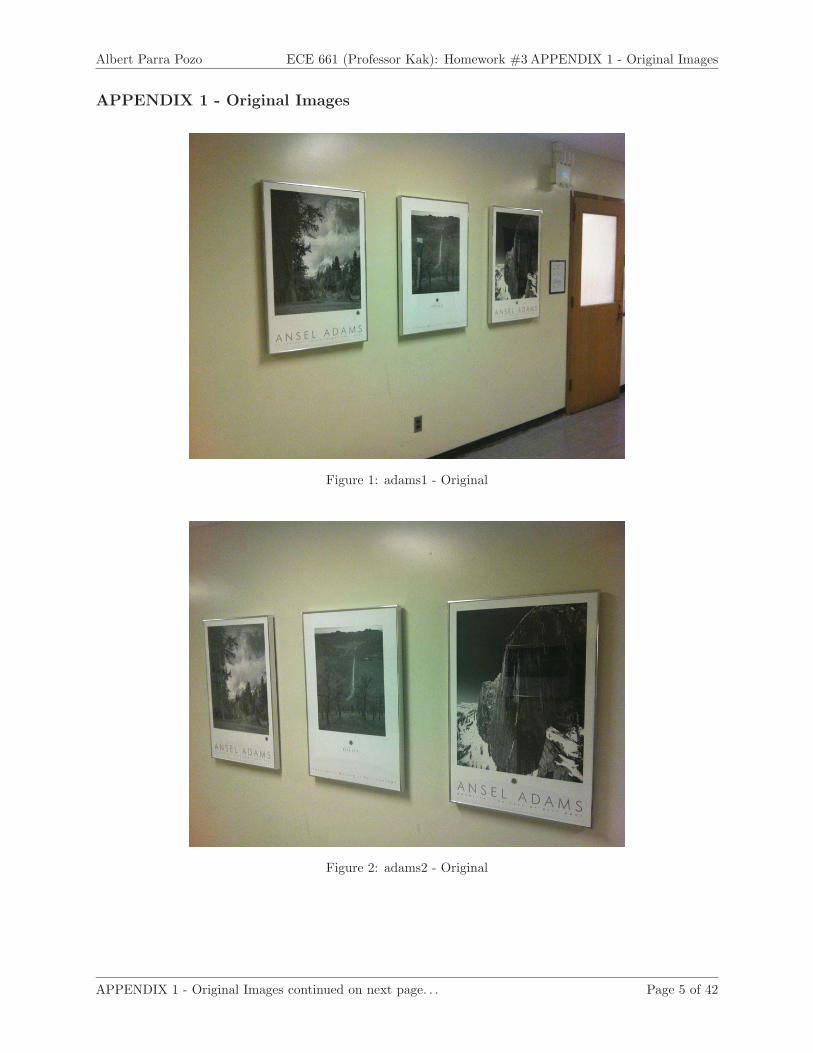
APPENDIX 2 - Two-Step Method
Figure 11: adams1 - Projective distortion removed
Figure 12: adams1 - Affine distortion removed
APPENDIX 2 - Two-Step Method continued on next page. . . Page 10 of 42

Albert Parra Pozo ECE 661 (Professor Kak): Homework #3APPENDIX 2 - Two-Step Method
Figure 13: adams2 - Projective distortion removed
Figure 14: adams2 - Affine distortion removed
APPENDIX 2 - Two-Step Method continued on next page. . . Page 11 of 42

Albert Parra Pozo ECE 661 (Professor Kak): Homework #3APPENDIX 2 - Two-Step Method
Figure 15: board1 - Projective distortion removed
Figure 16: board1 - Affine distortion removed
APPENDIX 2 - Two-Step Method continued on next page. . . Page 12 of 42

Albert Parra Pozo ECE 661 (Professor Kak): Homework #3APPENDIX 2 - Two-Step Method
Figure 17: board2 - Projective distortion removed
APPENDIX 2 - Two-Step Method continued on next page. . . Page 13 of 42

Albert Parra Pozo ECE 661 (Professor Kak): Homework #3APPENDIX 2 - Two-Step Method
Figure 18: board2 - Affine distortion removed
APPENDIX 2 - Two-Step Method continued on next page. . . Page 14 of 42

Albert Parra Pozo ECE 661 (Professor Kak): Homework #3APPENDIX 2 - Two-Step Method
Figure 19: door1 - Projective distortion removed
Figure 20: door1 - Affine distortion removed
APPENDIX 2 - Two-Step Method continued on next page. . . Page 15 of 42

Albert Parra Pozo ECE 661 (Professor Kak): Homework #3APPENDIX 2 - Two-Step Method
Figure 21: door2 - Projective distortion removed
Figure 22: door2 - Affine distortion removed
APPENDIX 2 - Two-Step Method continued on next page. . . Page 16 of 42

Albert Parra Pozo ECE 661 (Professor Kak): Homework #3APPENDIX 2 - Two-Step Method
Figure 23: tree1 - Projective distortion removed
Figure 24: tree1 - Affine distortion removed
APPENDIX 2 - Two-Step Method continued on next page. . . Page 17 of 42

Albert Parra Pozo ECE 661 (Professor Kak): Homework #3APPENDIX 2 - Two-Step Method
Figure 25: tree2 - Projective distortion removed
Figure 26: tree2 - Affine distortion removed
APPENDIX 2 - Two-Step Method continued on next page. . . Page 18 of 42

Albert Parra Pozo ECE 661 (Professor Kak): Homework #3APPENDIX 2 - Two-Step Method
Figure 27: check - Projective distortion removed
Figure 28: check - Affine distortion removed
APPENDIX 2 - Two-Step Method continued on next page. . . Page 19 of 42

Albert Parra Pozo ECE 661 (Professor Kak): Homework #3APPENDIX 2 - Two-Step Method
Figure 29: key - Projective distortion removed
Figure 30: key - Affine distortion removed
Page 20 of 42

Albert Parra Pozo ECE 661 (Professor Kak): Homework #3APPENDIX 3 - One-Step Method
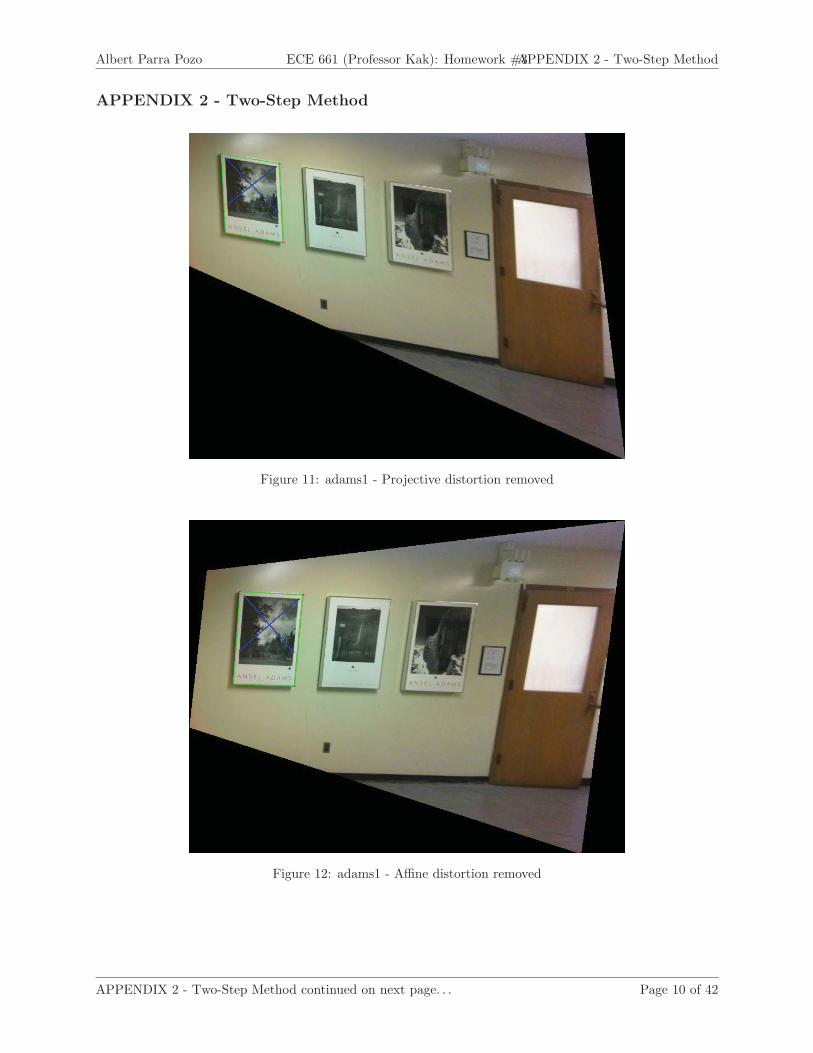
APPENDIX 3 - One-Step Method
Figure 31: adams1 - Projective and Affine distortions removed
APPENDIX 3 - One-Step Method continued on next page. . . Page 21 of 42
Albert Parra Pozo ECE 661 (Professor Kak): Homework #3APPENDIX 3 - One-Step Method
Figure 32: adams2 - Projective and Affine distortions removed
APPENDIX 3 - One-Step Method continued on next page. . . Page 22 of 42

Albert Parra Pozo ECE 661 (Professor Kak): Homework #3APPENDIX 3 - One-Step Method
Figure 33: board1 - Projective and Affine distortions removed
Figure 34: board2 - Projective and Affine distortions removed
APPENDIX 3 - One-Step Method continued on next page. . . Page 23 of 42

Albert Parra Pozo ECE 661 (Professor Kak): Homework #3APPENDIX 3 - One-Step Method
Figure 35: door1 - Projective and Affine distortions removed
APPENDIX 3 - One-Step Method continued on next page. . . Page 24 of 42

Albert Parra Pozo ECE 661 (Professor Kak): Homework #3APPENDIX 3 - One-Step Method
Figure 36: door2 - Projective and Affine distortions removed
APPENDIX 3 - One-Step Method continued on next page. . . Page 25 of 42

Albert Parra Pozo ECE 661 (Professor Kak): Homework #3APPENDIX 3 - One-Step Method
Figure 37: tree1 - Projective and Affine distortions removed
Figure 38: tree2 - Projective and Affine distortions removed
APPENDIX 3 - One-Step Method continued on next page. . . Page 26 of 42

Albert Parra Pozo ECE 661 (Professor Kak): Homework #3APPENDIX 3 - One-Step Method
Figure 39: check2 - Projective and Affine distortions removed
APPENDIX 3 - One-Step Method continued on next page. . . Page 27 of 42

Albert Parra Pozo ECE 661 (Professor Kak): Homework #3APPENDIX 3 - One-Step Method
Figure 40: key1 - Projective and Affine distortions removed
APPENDIX 3 - One-Step Method continued on next page. . . Page 28 of 42

Albert Parra Pozo ECE 661 (Professor Kak): Homework #3APPENDIX 3 - One-Step Method
APPENDIX 4 - Code
/*
* 2steps.cpp
*
* Created on: Sep 15, 2012
5 * Author: albertparra
*/
#include <cv.h>
#include <highgui.h>
10 #include <iostream>
using namespace std;
using namespace cv;
15 const char* winName = "Select Points";
Mat imgIn;
vector<Point3d> pointsDistProj;
vector<Point3d> pointsDistAff;
20 int idxPoints = 0;
// Setup mouse callbacks to register points when user clicks
void on_mouse(int event, int x, int y, int /*flags*/, void*) {
i f (imgIn.empty())
25 return;
i f (event == CV_EVENT_LBUTTONUP) {
idxPoints++;
30
cout << "Point: [" << x << ", " << y << "]" << endl;
// Draw circle on selected point location
circle(imgIn, Point(x, y), 3, CV_RGB(255, 0, 0), -1);
35
i f (idxPoints < 6) {
pointsDistProj.push_back(Point3d(x, y, 1));
i f (idxPoints > 1) {
40 // Draw l ine between points
Point3d p1 = pointsDistProj[idxPoints - 2];
Point3d p2 = pointsDistProj[idxPoints - 1];
// Draw lines joining points
45 l ine(imgIn, Point2d(p1.x, p1.y), Point2d(p2.x, p2.y),
CV_RGB(0, 255, 0), 2);
}
} else i f (idxPoints < 10) {
50 pointsDistAff.push_back(Point3d(x, y, 1));
APPENDIX 4 - Code continued on next page. . . Page 29 of 42

Albert Parra Pozo ECE 661 (Professor Kak): Homework #3 APPENDIX 4 - Code
i f (idxPoints % 2 == 1) {
// Draw l ine between points
Point3d p1 = pointsDistAff[idxPoints - 7];
55 Point3d p2 = pointsDistAff[idxPoints - 6];
// Draw lines joining points
l ine(imgIn, Point2d(p1.x, p1.y), Point2d(p2.x, p2.y),
CV_RGB(0, 0, 255), 2);
60 }
}
imshow(winName, imgIn);
}
65 }
// Correct input image given a homography
Mat correct_distortion(Mat imgIn, Mat H, String filename, String append) {
70 // Declare index variables
int idxRow, idxCol;
// Create vector with boundaries in image plane
vector<Point3d> coords_image;
75 coords_image.push_back(Point3d(0, 0, 1));
coords_image.push_back(Point3d(0, imgIn.rows - 1, 1));
coords_image.push_back(Point3d(imgIn.cols - 1, 0, 1));
coords_image.push_back(Point3d(imgIn.cols - 1, imgIn.rows - 1, 1));
80 cout << "coords_image = " << coords_image << endl;
// Compute corresponding coordinates in world plane
Mat M_coords_image = Mat(coords_image, true);
M_coords_image = M_coords_image.reshape(1, 4);
85
cout << "M_coords_image t = " << M_coords_image.t() << endl;
Mat M_coords_world = H.inv() * M_coords_image.t();
90 cout << "M_coords_world = " << M_coords_world << endl;
// Normalize wrt third column
M_coords_world.row(0)
= M_coords_world.row(0).mul(1 / M_coords_world.row(2));
95 M_coords_world.row(1)
= M_coords_world.row(1).mul(1 / M_coords_world.row(2));
cout << "M_coords_world normalized = " << M_coords_world << endl;
100 // Get minimum and maximum coordinates
double xmin, xmax, ymin, ymax;
minMaxLoc(M_coords_world.row(0), &xmin, &xmax, 0, 0);
minMaxLoc(M_coords_world.row(1), &ymin, &ymax, 0, 0);
APPENDIX 4 - Code continued on next page. . . Page 30 of 42

Albert Parra Pozo ECE 661 (Professor Kak): Homework #3 APPENDIX 4 - Code
105 cout << "xmin = " << xmin << endl;
cout << "xmax = " << xmax << endl;
cout << "ymin = " << ymin << endl;
cout << "ymax = " << ymax << endl;
110 // Determine size of corrected image, keeping image width
double scale = imgIn.cols / (xmax - xmin);
double height_out = (int) ((ymax - ymin) * scale);
cout << "scale = " << scale << endl;
115 cout << "height_out = " << height_out << endl;
// Create corrected image (output image)
Mat image_out(height_out, imgIn.cols, CV_8UC3);
120 // Find values for corrected image by taking set of coordinates from world plane
//to image plane and interpolating values i f necessary
// Create temporary world and image coordinates
Mat coords_world_temp(3, 1, CV_64FC1);
125 Mat coords_image_temp(3, 1, CV_64FC1);
// Loop through size of corrected image at step = 1/scale
coords_world_temp.at<double> (2, 0) = 1; // Set third component to 1
double step = 1 / scale;
130 for (idxCol = 0; idxCol < image_out.cols; idxCol++) {
// Set x coordinate
coords_world_temp.at<double> (0, 0) = (double) idxCol * step + xmin;
for (idxRow = 0; idxRow < image_out.rows; idxRow++) {
// Declare temporary variables
135 double x, y, dx, dy;
// Set y coordinate
coords_world_temp.at<double> (1, 0) = (double) idxRow * step + ymin;
140 // Find x and y coordinates in image plane
coords_image_temp = H * coords_world_temp;
// Normalize wrt third coordinate
x = coords_image_temp.at<double> (0, 0) / coords_image_temp.at<
145 double> (2, 0);
y = coords_image_temp.at<double> (1, 0) / coords_image_temp.at<
double> (2, 0);
// Check i f coordinate falls outside image boundaries
150 i f (x < 0 || x > imgIn.cols - 1 || y < 0 || y > imgIn.rows - 1) {
// Nothing to do to current pixel. Ignore rest of inner loop
continue;
}
155 // Take decimal part of x and y coordinates
dx = x - (int) x;
dy = y - (int) y;
APPENDIX 4 - Code continued on next page. . . Page 31 of 42

Albert Parra Pozo ECE 661 (Professor Kak): Homework #3 APPENDIX 4 - Code
// If decimal part is non-zero, interpolate pixel value
160 Vec3b i00 = imgIn.at<Vec3b> (int(y), int(x));
i f (dx != 0.0 || dy != 0.0) {
Vec3b i10 = imgIn.at<Vec3b> (int(y), int(x + 1));
Vec3b i01 = imgIn.at<Vec3b> (int(y + 1), int(x));
Vec3b i11 = imgIn.at<Vec3b> (int(y + 1), int(x + 1));
165
image_out.at<Vec3b> (idxRow, idxCol) = i00 * (1 - dx)
* (1 - dy) + i10 * dx * (1 - dy) + i01 * (1 - dx) * dy
+ i11 * dx * dy;
} else {
170 image_out.at<Vec3b> (idxRow, idxCol) = i00;
}
}
}
175 cout << "Saving image..." << endl;
// Save corrected image
int lastindex = filename.find_last_of(".");
String rawname = filename.substr(0, lastindex);
180 imwrite(rawname.append("_").append(append).append(".jpg"), image_out);
return image_out;
}
185 // Normalize 3D point wrt third component
Point3d normPoint3d(Point3d p) {
p.x = p.x / p.z;
p.y = p.y / p.z;
p.z = 1;
190
return p;
}
// Covert 3x1 mat to Point3d
195 Point3d mat2point3d(Mat p) {
Point3d p3d = Point3d(p.at<double> (0), p.at<double> (1), p.at<double> (2));
return p3d;
}
200
// Compute homography for removing projective distortion
Mat homography_projective() {
// Compute vanishing l ine
Point3d l1 = pointsDistProj[0].cross(pointsDistProj[1]);
205 Point3d l2 = pointsDistProj[3].cross(pointsDistProj[2]);
Point3d l3 = pointsDistProj[1].cross(pointsDistProj[2]);
Point3d l4 = pointsDistProj[4].cross(pointsDistProj[3]);
Point3d P = l1.cross(l2);
Point3d Q = l3.cross(l4);
210 Point3d VL = P.cross(Q);
APPENDIX 4 - Code continued on next page. . . Page 32 of 42

Albert Parra Pozo ECE 661 (Professor Kak): Homework #3 APPENDIX 4 - Code
// Normalize vanishing l ine
VL = normPoint3d(VL);
215 cout << "Vanishing Line: " << VL << endl;
// Build homography matrix to correct projective distortion
Mat Hp = Mat::eye(3, 3, CV_64FC1);
Hp.at<double> (2, 0) = VL.x;
220 Hp.at<double> (2, 1) = VL.y;
Hp.at<double> (2, 2) = VL.z;
cout << "Hp = " << Hp << endl;
225 return Hp;
}
// Compute homography for removing affine distortion
Mat homography_affine(Mat Hp) {
230
// Compute two sets of orthogonal lines
Point3d l = pointsDistAff[0].cross(pointsDistAff[1]);
Point3d m = pointsDistAff[2].cross(pointsDistAff[3]);
Point3d n = pointsDistProj[0].cross(pointsDistProj[1]);
235 Point3d o = pointsDistProj[1].cross(pointsDistProj[2]);
// Correct projective distortion of original lines
Mat lmat = Hp.inv().t() * Mat(l, true);
Mat mmat = Hp.inv().t() * Mat(m, true);
240 Mat nmat = Hp.inv().t() * Mat(n, true);
Mat omat = Hp.inv().t() * Mat(o, true);
// Convert Mat back to Point3d
l = mat2point3d(lmat);
245 m = mat2point3d(mmat);
n = mat2point3d(nmat);
o = mat2point3d(omat);
cout << "l = " << l << endl;
250 cout << "m = " << m << endl;
cout << "n = " << n << endl;
cout << "o = " << o << endl;
// Build ml and b for system of equations ml*s = b (setting s22 = 1)
255 double mldata[2][2] = { { l.x * m.x, l.x * m.y + l.y * m.x }, { n.x * o.x,
n.x * o.y + n.y * o.x } };
double bdata[2][1] = { { -l.y * m.y }, { -n.y * o.y } };
Mat ML = Mat(2, 2, CV_64FC1, mldata);
Mat b = Mat(2, 1, CV_64FC1, bdata);
260
cout << "ML = " << ML << endl;
cout << "b = " << b << endl;
APPENDIX 4 - Code continued on next page. . . Page 33 of 42

Albert Parra Pozo ECE 661 (Professor Kak): Homework #3 APPENDIX 4 - Code
// Solve ml*s = b for s
265 Mat s = ML.inv() * b;
cout << "s = " << s << endl;
// Build S matrix
270 double Sdata[2][2] = { { s.at<double> (0), s.at<double> (1) }, { s.at<
double> (1), 1 } };
Mat S = Mat(2, 2, CV_64FC1, Sdata);
cout << "S = " << S << endl;
275
// Compute SVD of S
Mat U, D2, D, Ut;
SVD::compute(S, D2, U, Ut, 0);
280 cout << "U = " << U << endl;
cout << "Ut = " << Ut << endl;
cout << "D2 = " << D2 << endl;
// Find D from Dˆ2
285 pow(D2, 0.5, D);
D = Mat::diag(D);
cout << "D = " << D << endl;
290 // Build A
Mat A = U * D * U.inv();
cout << "A = " << A << endl;
295 // Build homography matrix to correct affine distortion
Mat Ha;
double Acdata[2][1] = { { 0 }, { 0 } };
Mat Ac = Mat(2, 1, CV_64FC1, Acdata);
hconcat(A, Ac, Ha);
300
double Ardata[1][3] = { { 0, 0, 1 } };
Mat Ar = Mat(1, 3, CV_64FC1, Ardata);
vconcat(Ha, Ar, Ha);
305 cout << "Ha = " << Ha << endl;
return Ha;
}
310 // Main function
int main(int argc, char** argv) {
cout << "Use:" << endl << " right mouse button - to add new points;"
<< endl << " key ’r’ - to run the program" << endl << endl;
315
// Load input image
APPENDIX 4 - Code continued on next page. . . Page 34 of 42

Albert Parra Pozo ECE 661 (Professor Kak): Homework #3 APPENDIX 4 - Code
i f (argc < 2) {
cout << " Usage: ece661hw2 image_path" << endl;
return -1;
320
} else {
imgIn = imread(argv[1], CV_LOAD_IMAGE_COLOR);
i f (!imgIn.data) // Check for invalid input
{
325 cout << "Could not open or find the image" << endl;
return -1;
}
}
330 // Show image in external window
namedWindow(winName, CV_WINDOW_AUTOSIZE);
imshow(winName, imgIn);
// Set mouse callback (to get points in image from user clicks)
335 cvSetMouseCallback(winName, on_mouse);
cout << "1) Select 4 points from a rectangle in the world plane to form"
<< "two sets of parallel lines" << endl
<< "2) Select 4 points forming two orthogonal lines in the world plane"
340 << endl;
for (;;) {
// Wait for user to press key
345 uchar key = (uchar) waitKey();
// Exit i f escape key pressed
i f (key == 27)
break;
350
// Run program i f ’r’ key pressed
i f (key == ’r’) {
// Compute homography for removing projective distortion
355 Mat Hp = homography_projective();
// Correct projective distortion
correct_distortion(imgIn, Hp.inv(), argv[1], "proj");
360 // Compute homography for removing affine distorion
Mat Ha = homography_affine(Hp);
// Correct affine distortion
correct_distortion(imgIn, Hp.inv() * Ha, argv[1], "affine");
365
return 0;
}
}
}
APPENDIX 4 - Code continued on next page. . . Page 35 of 42

Albert Parra Pozo ECE 661 (Professor Kak): Homework #3 APPENDIX 4 - Code
C++ code - 2steps.cpp
/*
* 1step.cpp
*
* Created on: Sep 15, 2012
5 * Author: albertparra
*/
#include <cv.h>
#include <highgui.h>
10 #include <iostream>
using namespace std;
using namespace cv;
15 const char* winName = "Select Points";
Mat imgIn;
vector<Point3d> pointsDist;
int idxPoints = 0;
20
// Setup mouse callbacks to register points when user clicks
void on_mouse(int event, int x, int y, int /*flags*/, void*) {
i f (imgIn.empty())
return;
25
i f (event == CV_EVENT_LBUTTONUP) {
idxPoints++;
30 cout << "Point: [" << x << ", " << y << "]" << endl;
// Draw circle on selected point location
circle(imgIn, Point(x, y), 3, CV_RGB(255, 0, 0), -1);
35 i f (idxPoints < 21) {
pointsDist.push_back(Point3d(x, y, 1));
i f (idxPoints % 2 == 0) {
// Draw l ine between points
40 Point3d p1 = pointsDist[idxPoints - 2];
Point3d p2 = pointsDist[idxPoints - 1];
// Draw lines joining points
l ine(imgIn, Point2d(p1.x, p1.y), Point2d(p2.x, p2.y),
45 CV_RGB(0, 255, 0), 2);
}
imshow(winName, imgIn);
}
50 }
}
// Correct input image given a homography
APPENDIX 4 - Code continued on next page. . . Page 36 of 42

Albert Parra Pozo ECE 661 (Professor Kak): Homework #3 APPENDIX 4 - Code
Mat correct_distortion(Mat imgIn, Mat H, String filename, String append) {
55 // Declare index variables
int idxRow, idxCol;
// Create vector with boundaries in image plane
vector<Point3d> coords_image;
60 coords_image.push_back(Point3d(0, 0, 1));
coords_image.push_back(Point3d(0, imgIn.rows - 1, 1));
coords_image.push_back(Point3d(imgIn.cols - 1, 0, 1));
coords_image.push_back(Point3d(imgIn.cols - 1, imgIn.rows - 1, 1));
65 cout << "coords_image = " << coords_image << endl;
// Compute corresponding coordinates in world plane
Mat M_coords_image = Mat(coords_image, true);
M_coords_image = M_coords_image.reshape(1, 4);
70
cout << "M_coords_image t = " << M_coords_image.t() << endl;
Mat M_coords_world = H.inv() * M_coords_image.t();
75 cout << "M_coords_world = " << M_coords_world << endl;
// Normalize wrt third column
M_coords_world.row(0)
= M_coords_world.row(0).mul(1 / M_coords_world.row(2));
80 M_coords_world.row(1)
= M_coords_world.row(1).mul(1 / M_coords_world.row(2));
cout << "M_coords_world normalized = " << M_coords_world << endl;
85 // Get minimum and maximum coordinates
double xmin, xmax, ymin, ymax;
minMaxLoc(M_coords_world.row(0), &xmin, &xmax, 0, 0);
minMaxLoc(M_coords_world.row(1), &ymin, &ymax, 0, 0);
90 cout << "xmin = " << xmin << endl;
cout << "xmax = " << xmax << endl;
cout << "ymin = " << ymin << endl;
cout << "ymax = " << ymax << endl;
95 // Determine size of corrected image, keeping image width
double scale = imgIn.cols / (xmax - xmin);
double height_out = (int) ((ymax - ymin) * scale);
cout << "scale = " << scale << endl;
100 cout << "height_out = " << height_out << endl;
// Create corrected image (output image)
Mat image_out(height_out, imgIn.cols, CV_8UC3);
105 // Find values for corrected image by taking set of coordinates from world plane
APPENDIX 4 - Code continued on next page. . . Page 37 of 42
Albert Parra Pozo ECE 661 (Professor Kak): Homework #3 APPENDIX 4 - Code
//to image plane and interpolating values i f necessary
// Create temporary world and image coordinates
Mat coords_world_temp(3, 1, CV_64FC1);
110 Mat coords_image_temp(3, 1, CV_64FC1);
// Loop through size of corrected image at step = 1/scale
coords_world_temp.at<double> (2, 0) = 1; // Set third component to 1
double step = 1 / scale;
115 for (idxCol = 0; idxCol < image_out.cols; idxCol++) {
// Set x coordinate
coords_world_temp.at<double> (0, 0) = (double) idxCol * step + xmin;
for (idxRow = 0; idxRow < image_out.rows; idxRow++) {
// Declare temporary variables
120 double x, y, dx, dy;
// Set y coordinate
coords_world_temp.at<double> (1, 0) = (double) idxRow * step + ymin;
125 // Find x and y coordinates in image plane
coords_image_temp = H * coords_world_temp;
// Normalize wrt third coordinate
x = coords_image_temp.at<double> (0, 0) / coords_image_temp.at<
130 double> (2, 0);
y = coords_image_temp.at<double> (1, 0) / coords_image_temp.at<
double> (2, 0);
// Check i f coordinate falls outside image boundaries
135 i f (x < 0 || x > imgIn.cols - 1 || y < 0 || y > imgIn.rows - 1) {
// Nothing to do to current pixel. Ignore rest of inner loop
continue;
}
140 // Take decimal part of x and y coordinates
dx = x - (int) x;
dy = y - (int) y;
// If decimal part is non-zero, interpolate pixel value
145 Vec3b i00 = imgIn.at<Vec3b> (int(y), int(x));
i f (dx != 0.0 || dy != 0.0) {
Vec3b i10 = imgIn.at<Vec3b> (int(y), int(x + 1));
Vec3b i01 = imgIn.at<Vec3b> (int(y + 1), int(x));
Vec3b i11 = imgIn.at<Vec3b> (int(y + 1), int(x + 1));
150
image_out.at<Vec3b> (idxRow, idxCol) = i00 * (1 - dx)
* (1 - dy) + i10 * dx * (1 - dy) + i01 * (1 - dx) * dy
+ i11 * dx * dy;
} else {
155 image_out.at<Vec3b> (idxRow, idxCol) = i00;
}
}
}
APPENDIX 4 - Code continued on next page. . . Page 38 of 42
Albert Parra Pozo ECE 661 (Professor Kak): Homework #3 APPENDIX 4 - Code
160 cout << "Saving image..." << endl;
// Save corrected image
int lastindex = filename.find_last_of(".");
String rawname = filename.substr(0, lastindex);
165 imwrite(rawname.append("_").append(append).append(".jpg"), image_out);
return image_out;
}
170 // Normalize 3D point wrt third component
Point3d normPoint3d(Point3d p) {
p.x = p.x / p.z;
p.y = p.y / p.z;
p.z = 1;
175
return p;
}
// Compute homography for removing projective and affine distortions at the same time
180 Mat homography_projectiveaffine() {
// Compute five sets of orthogonal lines
Point3d l1 = pointsDist[0].cross(pointsDist[1]);
Point3d m1 = pointsDist[2].cross(pointsDist[3]);
185 Point3d l2 = pointsDist[4].cross(pointsDist[5]);
Point3d m2 = pointsDist[6].cross(pointsDist[7]);
Point3d l3 = pointsDist[8].cross(pointsDist[9]);
Point3d m3 = pointsDist[10].cross(pointsDist[11]);
Point3d l4 = pointsDist[12].cross(pointsDist[13]);
190 Point3d m4 = pointsDist[14].cross(pointsDist[15]);
Point3d l5 = pointsDist[16].cross(pointsDist[17]);
Point3d m5 = pointsDist[18].cross(pointsDist[19]);
cout << "l1 = " << l1 << endl;
195 cout << "m1 = " << m1 << endl;
cout << "l2 = " << l2 << endl;
cout << "m2 = " << m2 << endl;
cout << "l3 = " << l3 << endl;
cout << "m3 = " << m3 << endl;
200 cout << "l4 = " << l4 << endl;
cout << "m4 = " << m4 << endl;
cout << "l5 = " << l5 << endl;
cout << "m5 = " << m5 << endl;
205 // Build w and z for system of equations w*z = b
double wdata[5][5] = { { l1.x * m1.x, (l1.x * m1.y + l1.y * m1.x) / 2, l1.y
* m1.y, (l1.x * m1.z + l1.z * m1.x) / 2,
(l1.y * m1.z + l1.z * m1.y) / 2 }, { l2.x * m2.x, (l2.x * m2.y
+ l2.y * m2.x) / 2, l2.y * m2.y, (l2.x * m2.z + l2.z * m2.x) / 2,
210 (l2.y * m2.z + l2.z * m2.y) / 2 }, { l3.x * m3.x, (l3.x * m3.y
+ l3.y * m3.x) / 2, l3.y * m3.y, (l3.x * m3.z + l3.z * m3.x) / 2,
APPENDIX 4 - Code continued on next page. . . Page 39 of 42

Albert Parra Pozo ECE 661 (Professor Kak): Homework #3 APPENDIX 4 - Code
(l3.y * m3.z + l3.z * m3.y) / 2 }, { l4.x * m4.x, (l4.x * m4.y
+ l4.y * m4.x) / 2, l4.y * m4.y, (l4.x * m4.z + l4.z * m4.x) / 2,
(l4.y * m4.z + l4.z * m4.y) / 2 }, { l5.x * m5.x, (l5.x * m5.y
215 + l5.y * m5.x) / 2, l5.y * m5.y, (l5.x * m5.z + l5.z * m5.x) / 2,
(l5.y * m5.z + l5.z * m5.y) / 2 } };
double bdata[5][1] = { { -l1.z * m1.z }, { -l2.z * m2.z },
{ -l3.z * m3.z }, { -l4.z * m4.z }, { -l5.z * m5.z } };
220 Mat W = Mat(5, 5, CV_64FC1, wdata);
Mat b = Mat(5, 1, CV_64FC1, bdata);
cout << "W = " << W << endl;
cout << "b = " << b << endl;
225
Mat z = W.inv() * b;
cout << "z = " << z << endl;
230 // Build Cinf matrix
double Cinfdata[3][3] = { { z.at<double> (0), z.at<double> (1) / 2, z.at<
double> (3) / 2 }, { z.at<double> (1) / 2, z.at<double> (2), z.at<
double> (4) / 2 },
{ z.at<double> (3) / 2, z.at<double> (4) / 2, 1 } };
235 Mat Cinf = Mat(3, 3, CV_64FC1, Cinfdata);
cout << "Cinf = " << Cinf << endl;
// Compute SVD of Cinf
240 Mat U, D, Ut;
SVD::compute(Cinf, D, U, Ut, 0);
cout << "U = " << U << endl;
cout << "Ut = " << Ut << endl;
245 cout << "D = " << D << endl;
// Compute A
Mat AAt = Cinf(Range(0, 2), Range(0, 2));
250 cout << "AAt = " << AAt << endl;
Mat D2;
SVD::compute(AAt, D2, U, Ut, 0);
255 cout << "U = " << U << endl;
cout << "Ut = " << Ut << endl;
// Find D from Dˆ2
pow(D2, 0.5, D);
260 D = Mat::diag(D);
Mat A = U * D * Ut;
cout << "A = " << A << endl;
APPENDIX 4 - Code continued on next page. . . Page 40 of 42

Albert Parra Pozo ECE 661 (Professor Kak): Homework #3 APPENDIX 4 - Code
265
// Build system Av = Cinfsub
double Cinfsubdata[2][1] = { { Cinf.at<double> (0, 2) }, {
Cinf.at<double> (1, 2) } };
Mat Cinfsub(2, 1, CV_64FC1, Cinfsubdata);
270
cout << "Cinfsub = " << Cinfsub << endl;
// Solve system Av = Cinfsub for v
Mat v;
275 solve(A, Cinfsub, v, CV_LU);
cout << "v = " << v << endl;
// Build homography matrix to correct projective and affine distortion
280 Mat H;
double Hrdata[2][1] = { { 0 }, { 0 } };
Mat Hr = Mat(2, 1, CV_64FC1, Hrdata);
hconcat(A, Hr, H);
285
double Hddata[1][3] = { { v.at<double> (0), v.at<double> (1), 1 } };
Mat Hd = Mat(1, 3, CV_64FC1, Hddata);
vconcat(H, Hd, H);
290 cout << "H = " << H << endl;
return H;
}
295 // Main function
int main(int argc, char** argv) {
cout << "Use:" << endl << " right mouse button - to add new points;"
<< endl << " key ’r’ - to run the program" << endl << endl;
300
// Load input image
i f (argc < 2) {
cout << " Usage: ece661hw2 image_path" << endl;
return -1;
305
} else {
imgIn = imread(argv[1], CV_LOAD_IMAGE_COLOR);
i f (!imgIn.data) // Check for invalid input
{
310 cout << "Could not open or find the image" << endl;
return -1;
}
}
315 // Show image in external window
namedWindow(winName, CV_WINDOW_AUTOSIZE);
imshow(winName, imgIn);
APPENDIX 4 - Code continued on next page. . . Page 41 of 42

Albert Parra Pozo ECE 661 (Professor Kak): Homework #3 APPENDIX 4 - Code
// Set mouse callback (to get points in image from user clicks)
320 cvSetMouseCallback(winName, on_mouse);
cout
<< "1) Select 15 points from orthogonal lines in the world plane to form"
<< "five sets of parallel lines" << endl;
325
for (;;) {
// Wait for user to press key
uchar key = (uchar) waitKey();
330
// Exit i f escape key pressed
i f (key == 27)
break;
335 // Run program i f ’r’ key pressed
i f (key == ’r’) {
// Compute homography for removing projective distortion
Mat H = homography_projectiveaffine();
340
// Correct projective distortion
correct_distortion(imgIn, H, argv[1], "proj&affine");
return 0;
345 }
}
}
C++ code - 1step.cpp
Page 42 of 42