Embed Size (px)
Citation preview

ECE 4680 DSP Laboratory 3:Introduction to Code Composer Studio and
the Zoom OMAP-L138 BoardDue 12:15 PM Friday, October 10, 2014
In this lab you will get introduced to the hardware and software tools that you will be usingthroughout the rest of the semester. Think of it as a grand tour into some of the many facets of theeclipse-based integrated development environment (IDE) known as Code Composer Studio(CCS). The required course text1 will be used in what follows and all of the remaining labs.
An updated version of the software from the CD included with the text has been copied ontothe lab computers. The location is c:/CD. Certain executables that are discussed in later chaptershave not been installed at this time. If and when we need those applications the installation of thissoftware will take place.
A short lab report is due which documents code you have written and a summary of yourresults. Screen shots from the scope and any other instruments and software tools should beincluded as well.
Problems1. Work through Appendix A of the text as found in the update document
App_CCS_5_1_omapl138.pdf contained in the Lab 3 ZIP file. This document too isalso a bit dated, as it was written for CCS 5.1 and CCS 5.5 is the version currently runningin the lab. An in-class demo of the working project, including playing a 1 kHz sinusoidaltone through the Zoom OMAP L-138 board and viewed on the scope is expected. Use a labfunction generator as input to the analog-to-digital converter (ADC) and a scope for thisdemo. The lab instructor will show you where to find adaptor cables to convert from 3.5 mmjacks on the OMAP ZOOM board to phono jack and finally to BNC.
Note: The waveform will not be appear clean and sharp as you might expect. The digital-to-analog converter (DAC) contains a small leakage signal from sigma-delta DAC switchingwaveforms and perhaps from a switching power supply (LDO). The DAC lowpass recon-struction filter does its job of converting the samples to a continuous-time waveform, how-ever the leakage signal enters the output port through a board design issue. See the DACoutput for a 1 kHz input in the following figure, captured using the Analog Discovery2.
1. Thad Welch, Cameron Wright, and Michael Morrow, Real-Time Digital Signal Processing from MATLAB to C with the TMS320C6x DSK, second edition, CRC Taylor and Francis Group, Boca Raton, FL., 2012. ISBN 1439883033.
2. http://www.digilentinc.com/Products/Detail.cfm?Prod=ANALOG-DISCOVERY
Problems 1

ECE 4680 DSP Laboratory 3: Introduction to Code Composer Studio and the Zoom OMAP-L138 Board
When you listen to this signal through ear buds or the PC speakers on the lab bench you do nothear the noise because it is at a frequency range above your hearing. A spectrum analyzer plotshows the offending portions of the DAC output frequency spectrum.
To allow you to view a clean waveform on the scope, a stereo 3.5 mm cable is available in the labwhich contains a three section passive lowpass filter (LPF) to remove the high frequency noiseabove 20 kHz. See the appendix of this handout for details on the design of this filter using Agi-lent ADS. With the LPF cable in place the scope trace is very clear as seen in the figure below.
1 kHz sinusoid fromfunction generator
Noise spectrum fromthe power supply leakinginto the DAC output
~1.25 MHz
Problems 2

ECE 4680 DSP Laboratory 3: Introduction to Code Composer Studio and the Zoom OMAP-L138 Board
Sampling Theory
Using your knowledge of sampling theory and aliasing (recall what you learned in ECE2610), you will now make some additional observations. For sampling rate the lowpasssampling theorem says that a system composed of an ADC followed by a DAC has a usablefrequency band from zero to Hz. Signals entering the system above will bealiased back to the fundamental alias frequency band. The ADC employed on theZoom board (tlv320aic3106) incorporates an anti-aliasing filter that effectively prevents sig-nals above Hz from passing to the output.
The sampling rate is set by uncommenting #define statements in the project header fileDSP_Config.h. Open this file in CCS (double-click the file name in the project tree) andverify that default setting is 48 kHz. With the program running, increase the frequency of thefunction generator and verify that the output disappears at about 24 kHz. Rebuild the projectwith the sampling rate reduced to 24 kHz and find the function generator frequency wherethe output disappears. Are your observations as expected?
2. Explore the use of Code Composer Studio (CCS) debugging related capabilities, such as set-ting break points, the watch window, graphical displays, and the memory window. Theapproach to this exercise is similar to what you have already done when you worked throughAppendix A of the text for Problem 1. The guided steps are provided below.
CCS Debugging
To get started begin by modifying the ISRs.c file you brought into the project of Problem1. The modified file is named ISRs_Lab3.c. and can be found in the ZIP packageLab3.zip. A slight change was also made to the file Startup.c, so replace this file too.The two areas of the original file that were change are shown below:
// Portions of ISRs_Lab3.c...
20 kHz Lowpass filter in-line
fs
fs 2⁄ fs 2⁄0 fs, 2⁄[ ]
fs 2⁄
Problems 3

ECE 4680 DSP Laboratory 3: Introduction to Code Composer Studio and the Zoom OMAP-L138 Board
/* add any global variables here */#define N_buffer 256 // define buffer length
float gain = 1.0; // gain variable controlled by gain.gel in Problem 3
short i = 0; // index for buffershort buffer[N_buffer]; // buffer to hold values for display in CCS
...interrupt void Codec_ISR(){
WriteDigitalOutputs(1); // Write to GPIO J15, pin 6; begin ISR timing pulse...
// this example simply copies sample data from in to outxLeft = CodecDataIn.Channel[ LEFT];xRight = CodecDataIn.Channel[ RIGHT];
// Do some floating operations with temp here// Presently a GEL gain control is implemented (see Problem 3)xRight *= gain;//==========================================
// Store samples in a short buffer for displaybuffer[i] = (short) xRight;i += 1;if (i >= N_buffer){
i = 0;}//==========================================
yLeft = xLeft;yRight = xRight;
CodecDataOut.Channel[ LEFT] = (short) yLeft;CodecDataOut.Channel[RIGHT] = (short) yRight;
/* end your code here */
WriteCodecData(CodecDataOut.UINT);// send output data to portWriteDigitalOutputs(0); // Write to GPIO J15, pin 6; end ISR timing pulse
}
Notice that some new global variables have been defined and some additional processing isnow inside the ISR. Other minor modifications have also been made in how data is receivedand transmitted to the audio codec (A/D–D/A). Still more changes are present, but are not aconcern now as they will be described in later problems. Note that the audio codec sends andreceives 16-bit signed integers (short in C), so formally you need to use a cast to convertfrom short to float and then float back to short again. A short array buffer[]
Problems 4

ECE 4680 DSP Laboratory 3: Introduction to Code Composer Studio and the Zoom OMAP-L138 Board
has been inserted to allow 256 samples of the input signal from the right channel to be held.This buffer is continuously being re-written by virtue of the if clause that resets the indexcounter i back to zero when i>=N_Buffer.
In the project MyFirstZOOM, remove the file ISRs.c and replace it withISRs_Lab3.c. You have two options here: (1) Create a clean project as in Problem 1, butnow using the two new files, or use your existing Problem 1 project with new files importedinto the project. Importing the new files into the existing project will give you some practicewith eclipse IDE project management capability. Adding the file StartUp.c will over-write the original file, no problem with this. The ISRs_Lab3.c file will now sit alongsideISRs.c. You need to exclude the file ISRs.c from the build by right-clicking over the filein the project tree as shown in the figure below:
Build the modified project and reload/load the .out file. We will now do some debugging.
• Input a 1 kHz, 500 mv peak, sinusoid into the right channel of the Line In jack.
• Connect a speaker or scope to the right channel line out to verify that the signal is being pro-
With the exclude ISRsin place, you now canrebuild the project byclicking the hammertoolbar button
new
excluded
Modified Project
Problems 5

ECE 4680 DSP Laboratory 3: Introduction to Code Composer Studio and the Zoom OMAP-L138 Board
cessed through the ISR by clicking the green Run button, Run menu item Resume, or theF8 key all work).
Breakpoints and the Watch Window
Suspend the program (alt-F8) and set a break-point in the code as shown below:
– Run the program again and see that it will now stop at the break-point you just set.
– Now, right-click over the array variable buffer, and select add to watch window.
Double-clickto placebreakpoint;
Run/ResumeSuspend &Halt debuggingbuttons
Note: You cansuspend andmodify, thenrebuild codewithout stoppingthe debugger;you just need tochange from thedebug perspective tothe editperspective
click the resumebutton
Problems 6

ECE 4680 DSP Laboratory 3: Introduction to Code Composer Studio and the Zoom OMAP-L138 Board
As you can see in the above screen shot, the watch window opens and you can expand thearray variable to see each element of the array buffer. Practice setting breakpoints bysetting one inside the if clause. When the program halts verify that i has indeed reached256.
– When a program is halted you can also hover the mouse pointer over any variable andsee its value and/or its memory address
– Note also that when you place a variable in the watch window you can also change it bydouble-clicking it; when you run again, execution continues with the variable change.
Note: This is the eclipse environment for TI programmable devices, which means it also canbe used to develop MSP430 code.
Graphical Display
The buffer contains a 256 sample record of the most recently processed samples. These sam-ples continuously write over old samples, so the buffer actually contains a discontinuity anytime you halt the processor to examine the buffer. The watch wind lets you look at the con-tents of an array, but with CCS graphical displays, you can plot the contents of a buffer andperform operations such as the FFT, to display the buffer in the frequency domain.
Right-click over buffer[]brings up this floatingmenu, add Watch and see this
Problems 7
ECE 4680 DSP Laboratory 3: Introduction to Code Composer Studio and the Zoom OMAP-L138 Board
With the processor halted go to the View menu and select Graph:Time/Frequency...
You will then see the Graph Property dialog.– Configure the start address to the variable name buffer (why is this a valid address?).
– Configure the acquisition buffer size and display data size both to 256 (N_buffer).
– Configure the DSP data type to short (16-bit signed integer).
– Finally configure the sampling rate to 48,000 Hz; this agrees with the setting in theDSK_Config.h file (see #define SamplingRateSetting).
– OK the dialog and a plot window will appear as shown below:
Use for a spectrum plot next
Buffer isfilling again
Problems 8

ECE 4680 DSP Laboratory 3: Introduction to Code Composer Studio and the Zoom OMAP-L138 Board
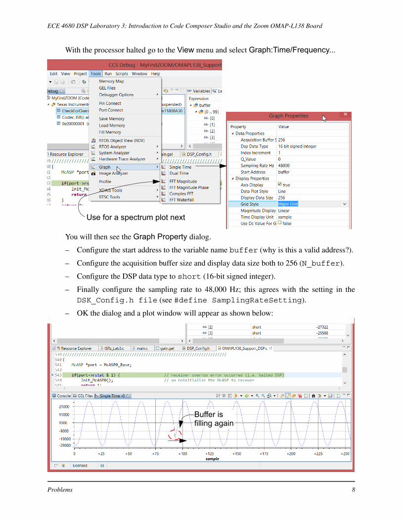
• At this point you can take measurement from the waveform by dragging the cursor aroundand reading the amplitude and time locations (time in seconds according to the entered sam-pling rate value is ignored by CCS for some reason).
• A second plot window can be opened to display the FFT magnitude of the data set
• Under Display Type, the top listed property, choose display FFT magnitude, then OK thedialog and observe the spectrum of a 256-point windowed sinusoid as shown below:
In the screen shot above you can see that the function generator input was at 1 kHz. Changethe input frequency to 9 kHz, run (F5) and then suspend the processor (alt-F8), then ver-ify with graph cursor that the frequency of the sinusoid is 9 kHz in the strange CCS scaling.
3. Text Chapter 2 Problem 1 (under Follow-On Challenges). You will augment this problem byimplementing a GUI gain scaling control using the CCS general purpose extension lan-guage (GEL). Fine the GEL file, gain.gel, in the Lab 3 ZIP package The guided steps forcreating and using a GEL slider for gain control is described below.
GEL Files
In this investigation you will learn how to use the general extension language (GEL) capa-bility of CCS to create a GUI slider control, can manipulate variables on code running on theOMAP-L138. You will later implement a panning fader, to continuously change the mixfrom left-to-right and right-to-left. One of the new global variables included in
The frequency axis scalingis hard to follow, but withfs = 48k and f0 = 1k, thenormalized sinusoid frequencyshould be 1/48 = 0.02083
Problems 9

ECE 4680 DSP Laboratory 3: Introduction to Code Composer Studio and the Zoom OMAP-L138 Board
ISRs_Lab3.c is
float gain = 1.0; // gain variable controlled by gain.gel
At present this variable has been fixed at 1.0, since there has been no outside control enabledto change the value. With a GEL file the value of this variable can be manipulated while theprogram is running under the control of CCS. A GEL file that performs this function islisted below.
/*gain.gel GEL slider to vary amplitude of signal in ISRs_Lab3.c */
menuitem "Input Gain"
slider Gain(0,50,4,1,gain_parameter) /*incr by 4, up to 50*/
{
/*vary gain_parameter over 0-50 then scale by 10 */
/* Range of values for gain is thus [0,50]/10 = [0,5.0] */
gain = (float) gain_parameter/10.0;
}
To load the GEL into the current project you first need to include the file in your project.Next start the debugger and from the debugger perspective you will be able access the GELFiles menu item under Tools. then from the File menu:
Once the file is loaded it will show up in the project workspace under the Scripts menu.Clicking this menu reveals the Input Gain item which contains a single slider gain.
First right-click toload the GEL file
Next, bring up theslider from theScripts menu
Problems 10

ECE 4680 DSP Laboratory 3: Introduction to Code Composer Studio and the Zoom OMAP-L138 Board
– In the GEL file listing notice that we created a menu item called “Input Gain”
– Under this menu item we have scripted a GUI slider element names Gain, which hasrange (integer steps) from 0 to 50, page-up/page-down steps of 1, and arrow left/arrowright of 1.
– This slider control then places its output variable, gain_parameter into the floatvariable gain, which is mapped to the matching variable gain in ISRs_Lab3.c.
To see the slider in action run the program (move the function generator frequency back to 1kHz) and notice as you move the slider up and down the signal amplitude will change; bestif you use the keyboard (page-up/down or arrow left/right), otherwise the action does notapply until you let go of the slider with the mouse
Reconfigure the function of the slider to implement a panning control between the right andleft audio channels. You will need to add some more variables and also receive and send outLEFT sample values. The algorithm is to make
(1)
where are the right and left input samples values, are the right and left outputsample values, and is a variable control by the slier that ranges over [0, 1]. In the sliderimplement this with an integer that runs over [0,100] then divide it down accordingly. Input
Ro 1 a–( )Ri aLi+=
Lo aRi 1 a–( )Li+=
Ri/Li Ro/Loa
Problems 11

ECE 4680 DSP Laboratory 3: Introduction to Code Composer Studio and the Zoom OMAP-L138 Board
two different audio sources to the left and right channels and then listen to what happens asyou move the slider up and down. Describe what this simple processing algorithm is doing.
4. In real-time DSP all of the DSP math that runs inside the ISR needs to complete before thesampling rate clock fires the next interrupt. Code profiling is one approach to time individ-ual sections of code CCS does indeed support this. WIth the digital output capability of theZoom OMAP-L138, it is possible to send an actual timing waveform to the digital outputsthat reflects the time spent in the ISR relative to the sampling rate clock.
The book describes the use of a support library function, WriteDigitalOutputs().This function outputs four bits to pins 6–9 of the LCD connector as shown below:
The only work being done by the ISR in ISRs_Lab3.c is copying input samples to out-put samples and filling display buffer. You expect this to be minimal. A logic analyzer plot isshown below for the case of sampling at 48 ksps:
When the ISR has more work to do in later labs, you will want to improve performanceusing the optimizing C compiler. For now you will characterize the performance of this sim-ple ISR under various optimization levels.
Under the Project menu you will find the Properties item (or alt+enter). This brings up adialog box that allows you to change compiler optimization settings:
pin 59pin 60
pin 1 (a ground pin)pin 2
Pins 6–9
Location of digital outputs, 1–4, on the 60-pin LCD header.
1/48k = 20.833 us
Problems 12

ECE 4680 DSP Laboratory 3: Introduction to Code Composer Studio and the Zoom OMAP-L138 Board
Insert a do-nothing for loop inside the ISR, e.g.,
short d = 0;
for(k=0; k<100; k++)
{
// Idle loop to load the processor inside the ISR
d += 1;
}
Initially set the number of iterations/loops to 100. Holding ksps increase the loopcount until the ISR service time is about 50% of the maximum time available, i.e. 20.833/2
s. Now investigate the speedup offered by setting the compiler optimization level to -o0, -o1, -o2, and -o3.
5. Text Chapter 2 Problem 2. Note that spectral inversion is described on p. 19 under basiceffect (2). A demo is expected, where you should experiment with both a sinusoidal tone andwith a high quality audio source, say an iPod or similar.
6. Text Chapter 2 Problem 5.
7. Text Chapter 2 Problems 6, 7, 8. Here you progressively limit the number of bits per sample.Comment on the audio quality as the number of bits is reduced. Demo this to the lab instruc-tor.
Pull down to select none or levels 0, 1, 2, or 3
fs 48=
μ
Problems 13

ECE 4680 DSP Laboratory 3: Introduction to Code Composer Studio and the Zoom OMAP-L138 Board
Appendix
Dr. Wickert’s Home Set-Up Using the Analog Discovery
Passive Lowpass Filter Design for DAC Noise ReductionConsider three passive filter designs build around 1000 ohm series resistors.
LPF
Digital
Scope
FctnGen
USB to PC
Power
Line In
Line Out
OnOff
Zoom OMAP-L138
Designin cable
Appendix 14

ECE 4680 DSP Laboratory 3: Introduction to Code Composer Studio and the Zoom OMAP-L138 Board
• Use the ADS Tuner to find a shunt C value that will produce a 3 dB frequency of about 20kHz.
Appendix 15