Embed Size (px)
Citation preview
ECE 4371, Fall, 2014
Introduction to Telecommunication Engineering/Telecommunication Laboratory
Zhu Han
Department of Electrical and Computer Engineering
Class 13
Oct. 8th, 2014
OutlineOutline Partial Response
Carrier systems – ASK, OOK, MASK
– FSK, MFSK
– BPSK, DBPSK, MPSK
– MQAM, MQPR
– OQPSK,
– Continuous phase modulation (CPM): MSK, GMSK
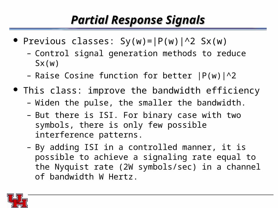
Partial Response SignalsPartial Response Signals
Previous classes: Sy(w)=|P(w)|^2 Sx(w)– Control signal generation methods to reduce Sx(w)
– Raise Cosine function for better |P(w)|^2
This class: improve the bandwidth efficiency– Widen the pulse, the smaller the bandwidth.
– But there is ISI. For binary case with two symbols, there is only few possible interference patterns.
– By adding ISI in a controlled manner, it is possible to achieve a signaling rate equal to the Nyquist rate (2W symbols/sec) in a channel of bandwidth W Hertz.
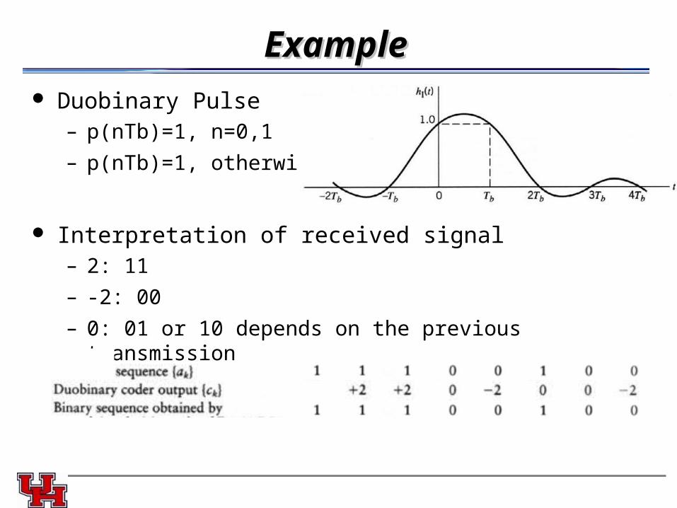
ExampleExample Duobinary Pulse
– p(nTb)=1, n=0,1
– p(nTb)=1, otherwise
Interpretation of received signal– 2: 11
– -2: 00
– 0: 01 or 10 depends on the previous transmission
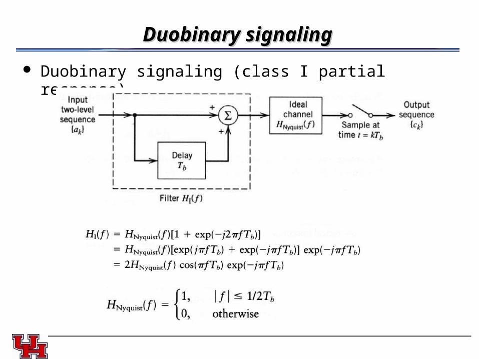
Duobinary signalingDuobinary signaling
Duobinary signaling (class I partial response)

Duobinary signal and Nyguist CriteriaDuobinary signal and Nyguist Criteria
Nyguist second criteria: but twice the bandwidth
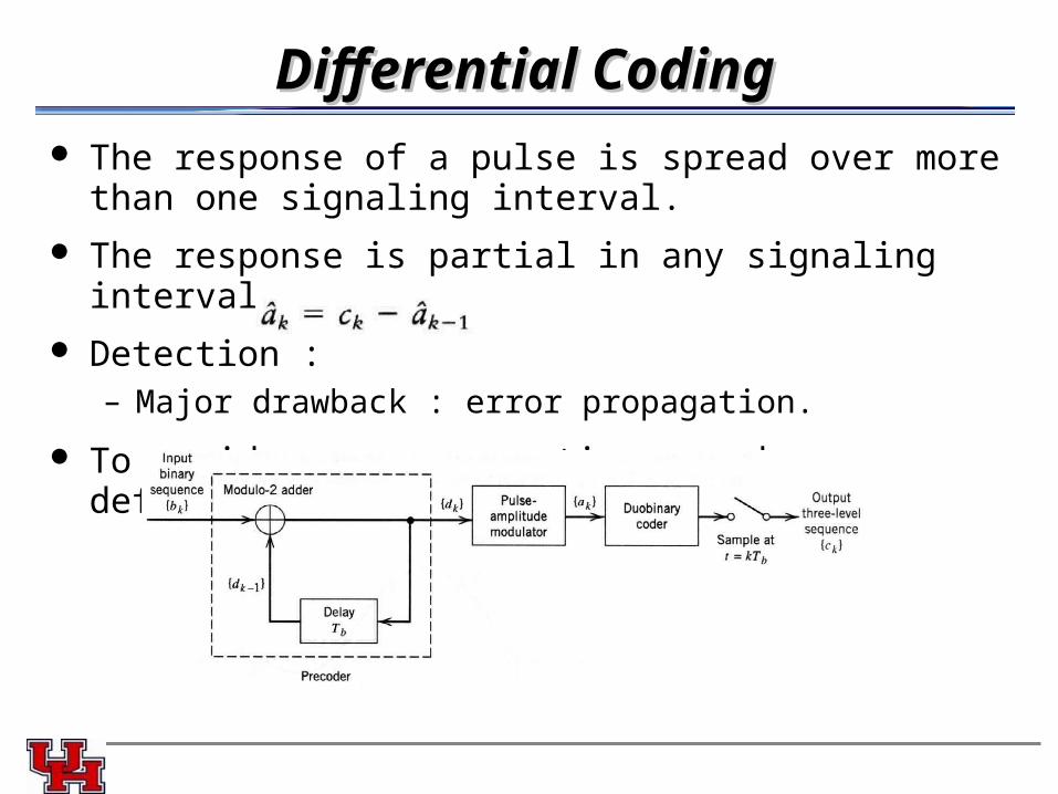
Differential CodingDifferential Coding The response of a pulse is spread over more than one signaling
interval.
The response is partial in any signaling interval.
Detection :– Major drawback : error propagation.
To avoid error propagation, need deferential coding (precoding).
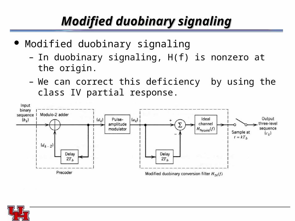
Modified duobinary signalingModified duobinary signaling
Modified duobinary signaling– In duobinary signaling, H(f) is nonzero at the origin.
– We can correct this deficiency by using the class IV partial response.
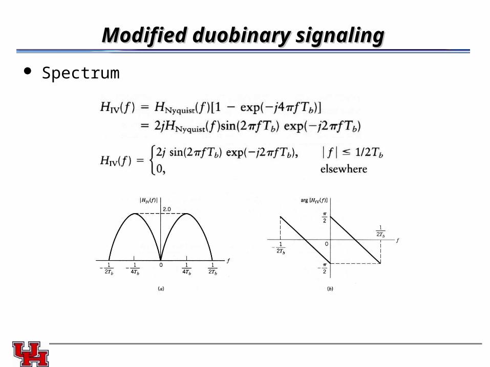
Modified duobinary signalingModified duobinary signaling
Spectrum
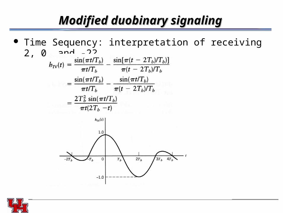
Modified duobinary signalingModified duobinary signaling
Time Sequency: interpretation of receiving 2, 0, and -2?
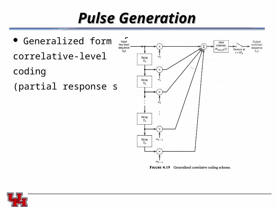
Pulse GenerationPulse Generation Generalized form of
correlative-level
coding
(partial response signaling)
TradeoffsTradeoffs Binary data transmission over a physical baseband channel can
be accomplished at a rate close to the Nyquist rate, using realizable filters with gradual cutoff characteristics.
Different spectral shapes can be produced, appropriate for the application at hand.
However, these desirable characteristics are achieved at a price :– A large SNR is required to yield the same average probability of
symbol error in the presence of noise.
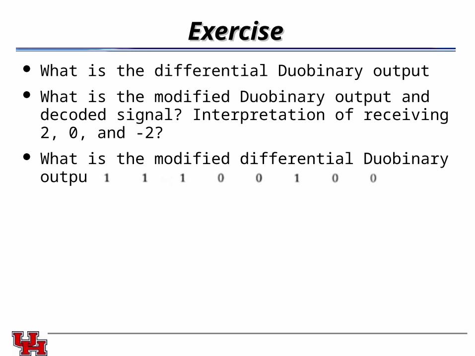
ExerciseExercise What is the differential Duobinary output
What is the modified Duobinary output and decoded signal? Interpretation of receiving 2, 0, and -2?
What is the modified differential Duobinary output
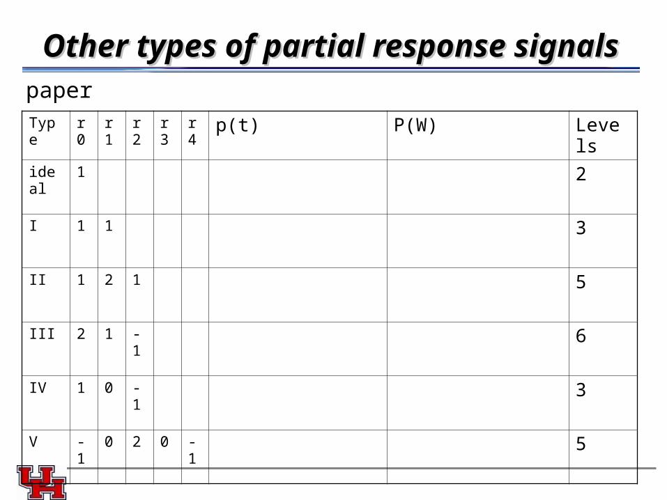
Other types of partial response signalsOther types of partial response signals
Type r0 r1 r2 r3 r4 p(t) P(W) Levels
ideal 1 2
I 1 1 3
II 1 2 1 5
III 2 1 -1 6
IV 1 0 -1 3
V -1 0 2 0 -1 5
paper
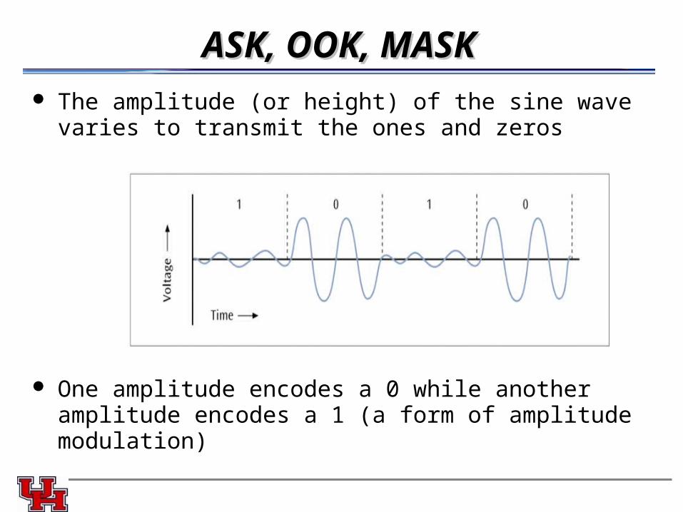
ASK, OOK, MASKASK, OOK, MASK The amplitude (or height) of the sine wave varies to transmit the
ones and zeros
One amplitude encodes a 0 while another amplitude encodes a 1 (a form of amplitude modulation)
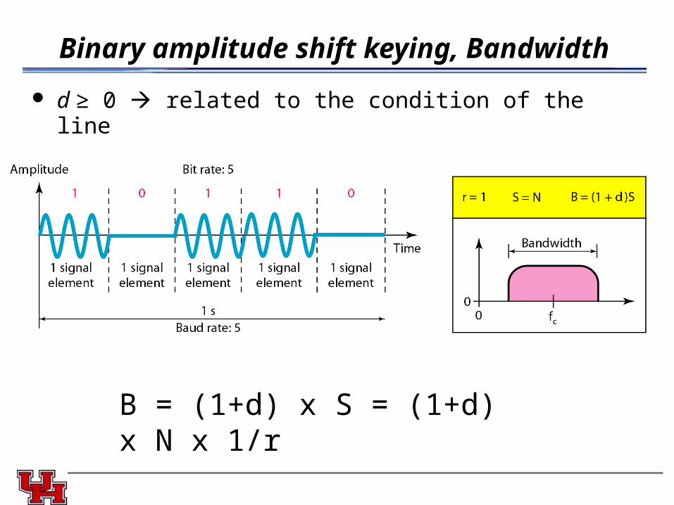
Binary amplitude shift keying, Bandwidth
d ≥ 0 related to the condition of the line
B = (1+d) x S = (1+d) x N x 1/r
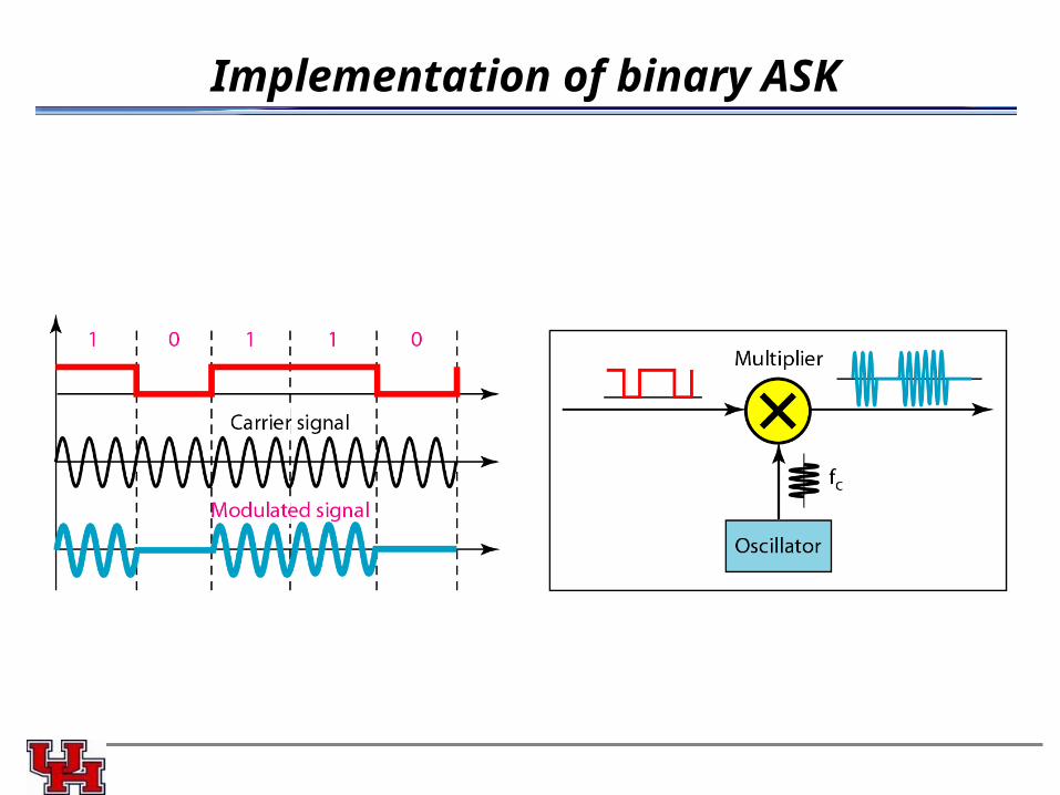
Implementation of binary ASK
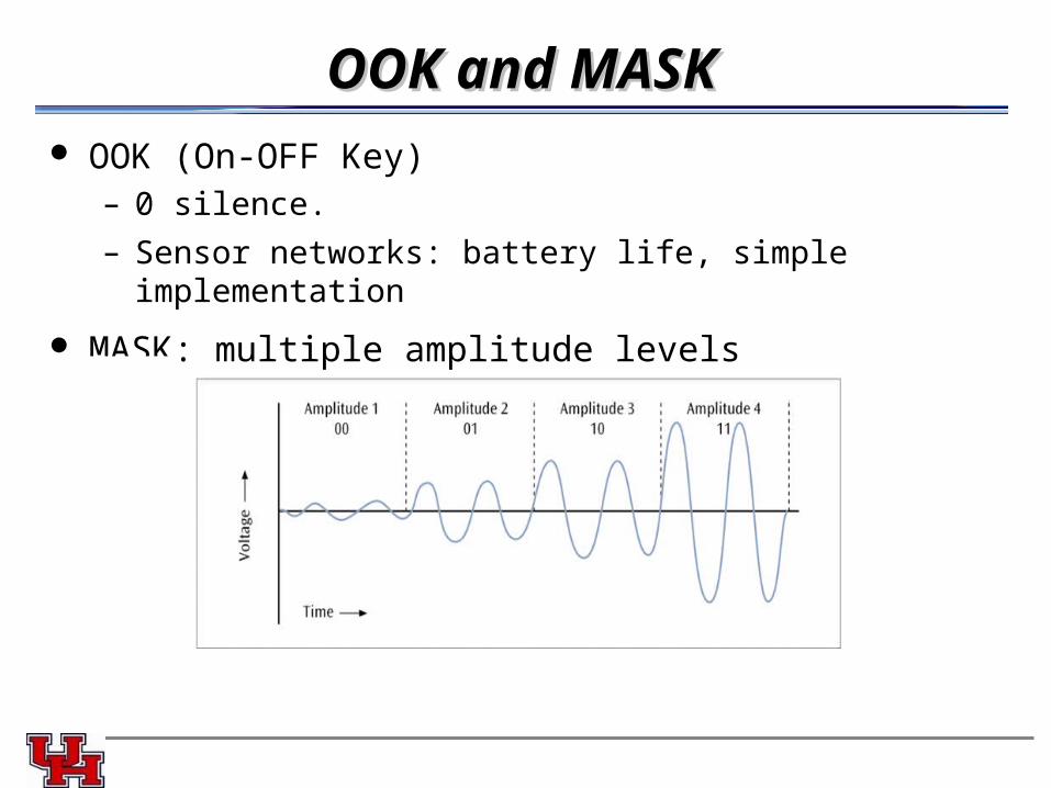
OOK and MASKOOK and MASK OOK (On-OFF Key)
– 0 silence.
– Sensor networks: battery life, simple implementation
MASK: multiple amplitude levels
Pro, Con and ApplicationsPro, Con and Applications Pro
– Simple implementation
Con– Major disadvantage is that telephone lines are very susceptible to
variations in transmission quality that can affect amplitude
– Susceptible to sudden gain changes
– Inefficient modulation technique for data
Applications– On voice-grade lines, used up to 1200 bps
– Used to transmit digital data over optical fiber
– Morse code
– Laser transmitters
Example
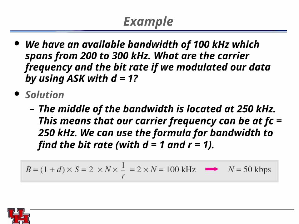
We have an available bandwidth of 100 kHz which spans from 200 to 300 kHz. What are the carrier frequency and the bit rate if we modulated our data by using ASK with d = 1?
Solution– The middle of the bandwidth is located at 250 kHz. This
means that our carrier frequency can be at fc = 250 kHz. We can use the formula for bandwidth to find the bit rate (with d = 1 and r = 1).
Frequency Shift KeyingFrequency Shift Keying
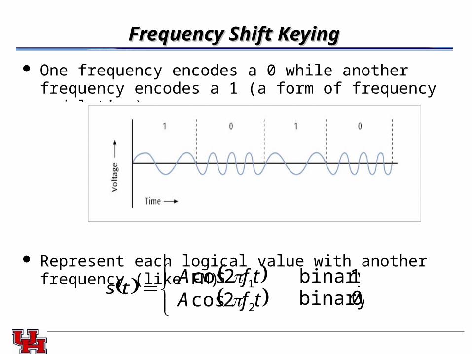
One frequency encodes a 0 while another frequency encodes a 1 (a form of frequency modulation)
Represent each logical value with another frequency (like FM)
ts tfA 12cos tfA 22cos
1binary 0binary
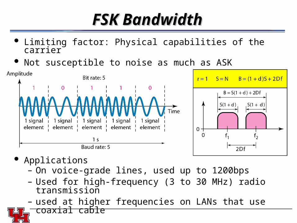
FSK BandwidthFSK Bandwidth Limiting factor: Physical capabilities of the carrier Not susceptible to noise as much as ASK
Applications– On voice-grade lines, used up to 1200bps– Used for high-frequency (3 to 30 MHz) radio transmission– used at higher frequencies on LANs that use coaxial cable
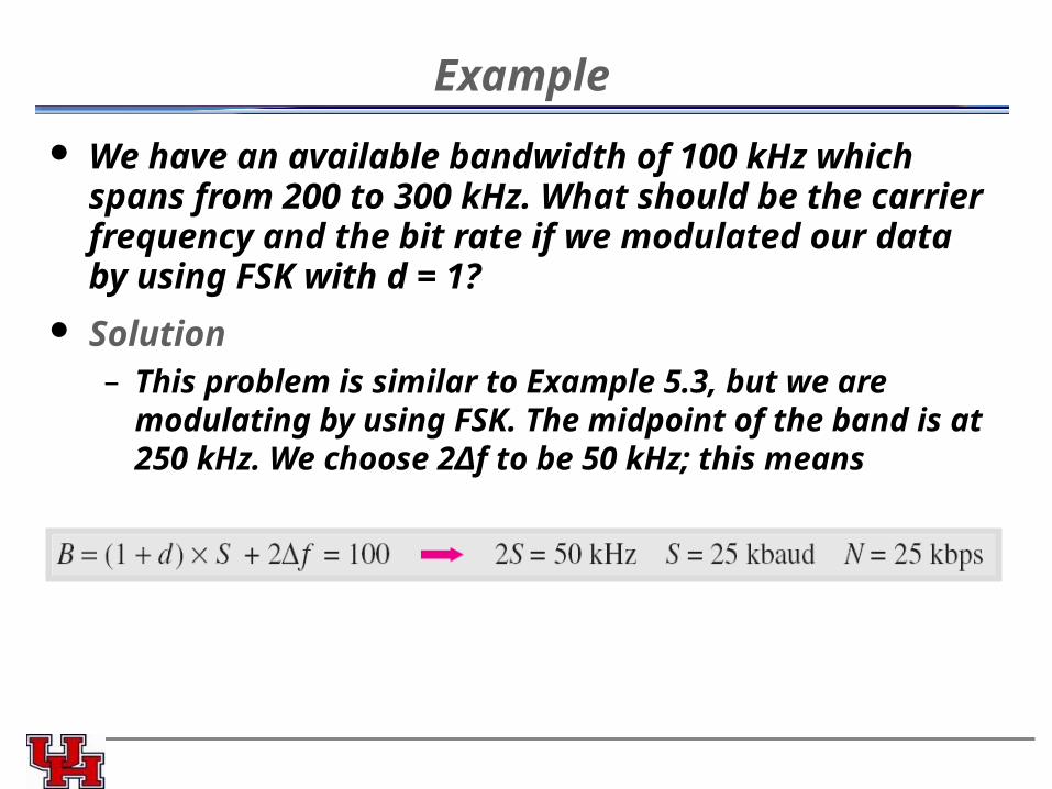
Example
We have an available bandwidth of 100 kHz which spans from 200 to 300 kHz. What should be the carrier frequency and the bit rate if we modulated our data by using FSK with d = 1?
Solution– This problem is similar to Example 5.3, but we are modulating
by using FSK. The midpoint of the band is at 250 kHz. We choose 2Δf to be 50 kHz; this means
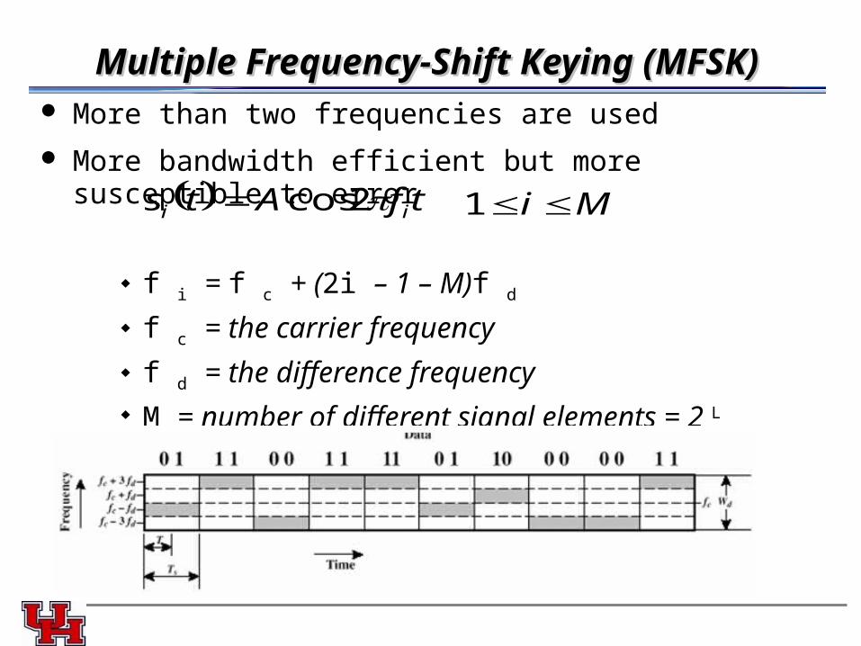
Multiple Frequency-Shift Keying (MFSK)Multiple Frequency-Shift Keying (MFSK) More than two frequencies are used
More bandwidth efficient but more susceptible to error
f i = f c + (2i – 1 – M)f d
f c = the carrier frequency f d = the difference frequency M = number of different signal elements = 2 L
L = number of bits per signal element
tfAts ii 2cos Mi 1
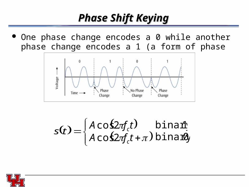
Phase Shift KeyingPhase Shift Keying
One phase change encodes a 0 while another phase change encodes a 1 (a form of phase modulation)
ts tfA c2cos tfA c2cos
1binary 0binary
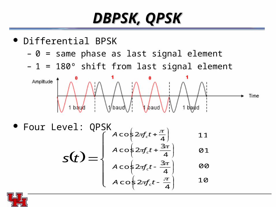
DBPSK, QPSKDBPSK, QPSK Differential BPSK
– 0 = same phase as last signal element
– 1 = 180º shift from last signal element
Four Level: QPSK
ts
42cos
tfA c 11
4
32cos
tfA c
4
32cos
tfA c
42cos
tfA c
01
00
10
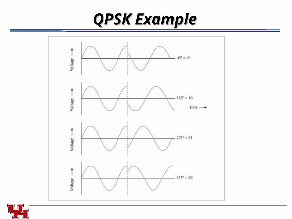
QPSK ExampleQPSK Example
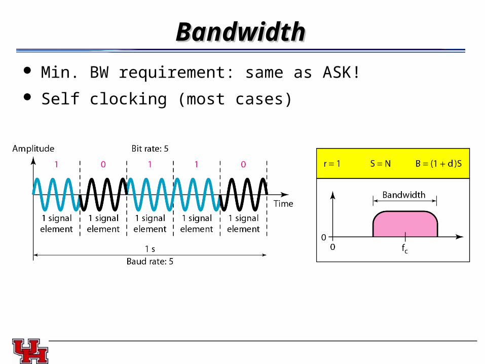
BandwidthBandwidth Min. BW requirement: same as ASK!
Self clocking (most cases)
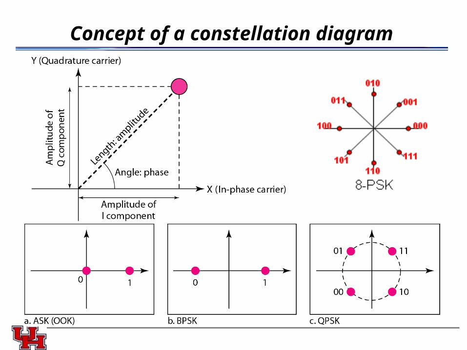
Concept of a constellation diagram
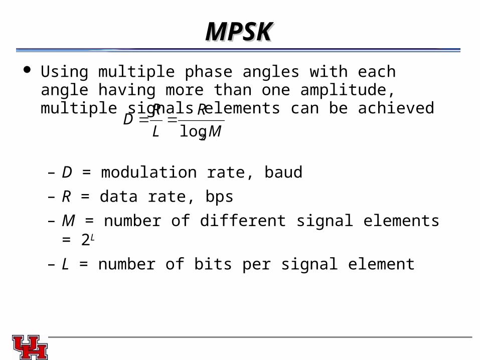
MPSKMPSK Using multiple phase angles with each angle having more than
one amplitude, multiple signals elements can be achieved
– D = modulation rate, baud
– R = data rate, bps
– M = number of different signal elements = 2L
– L = number of bits per signal element
M
R
L
RD
2log
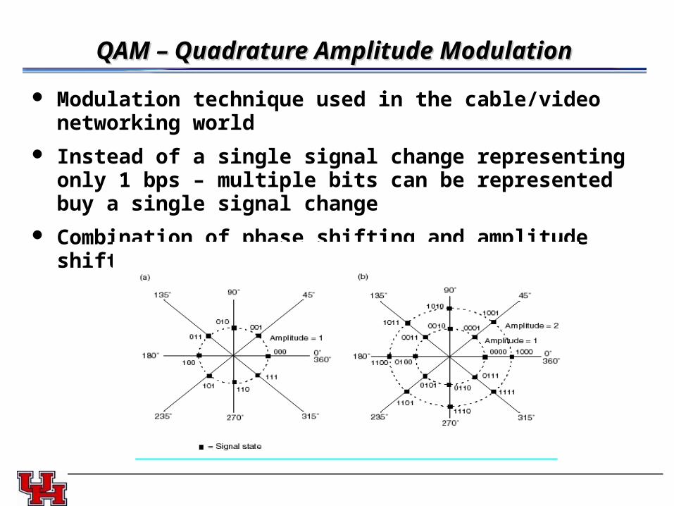
QAM – Quadrature Amplitude ModulationQAM – Quadrature Amplitude Modulation
Modulation technique used in the cable/video networking world
Instead of a single signal change representing only 1 bps – multiple bits can be represented buy a single signal change
Combination of phase shifting and amplitude shifting (8 phases, 2 amplitudes)
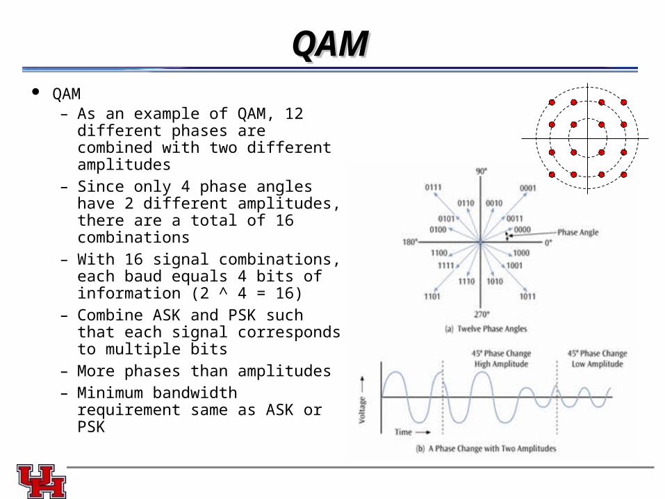
QAMQAM QAM
– As an example of QAM, 12 different phases are combined with two different amplitudes
– Since only 4 phase angles have 2 different amplitudes, there are a total of 16 combinations
– With 16 signal combinations, each baud equals 4 bits of information (2 ^ 4 = 16)
– Combine ASK and PSK such that each signal corresponds to multiple bits
– More phases than amplitudes– Minimum bandwidth requirement
same as ASK or PSK
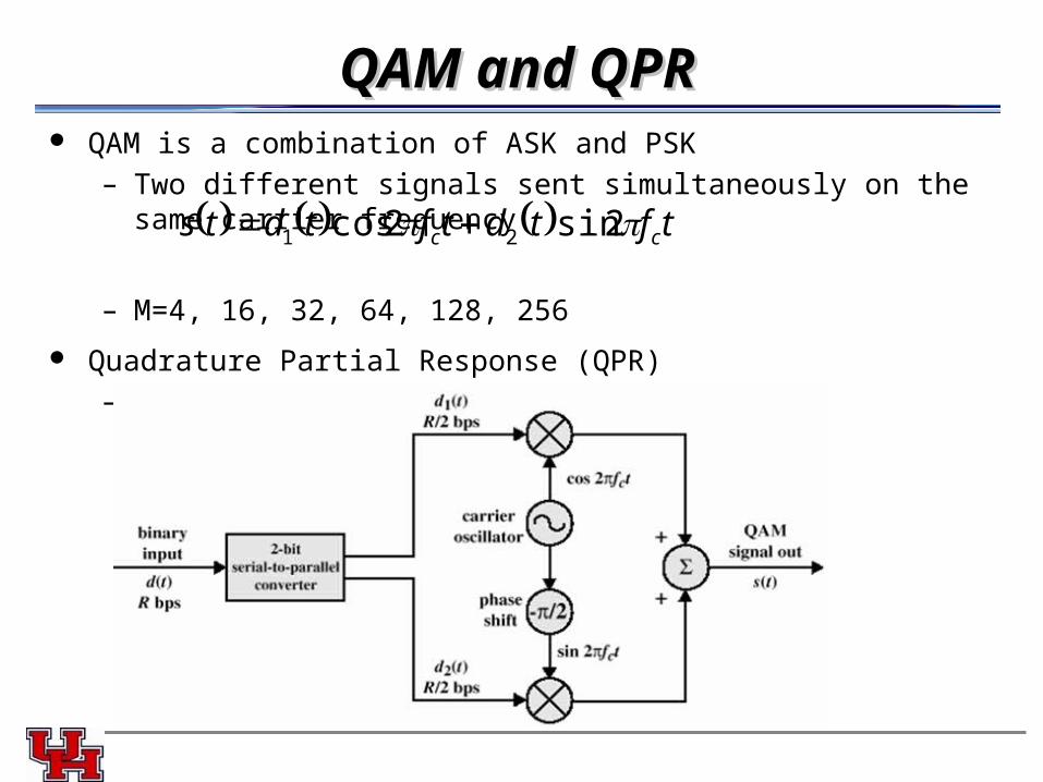
QAM and QPRQAM and QPR QAM is a combination of ASK and PSK
– Two different signals sent simultaneously on the same carrier frequency
– M=4, 16, 32, 64, 128, 256
Quadrature Partial Response (QPR)– 3 levels (+1, 0, -1), so 9QPR, 49QPR
tftdtftdts cc 2sin2cos 21
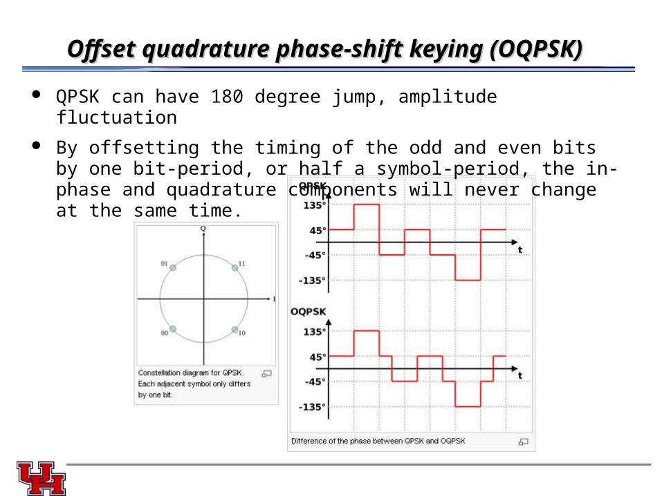
Offset quadrature phase-shift keying (OQPSK)Offset quadrature phase-shift keying (OQPSK)
QPSK can have 180 degree jump, amplitude fluctuation
By offsetting the timing of the odd and even bits by one bit-period, or half a symbol-period, the in-phase and quadrature components will never change at the same time.
ECE 4371 Fall 2008
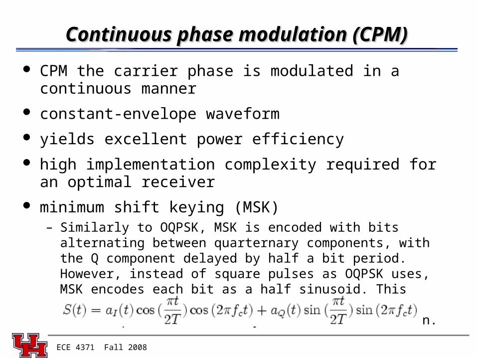
Continuous phase modulation (CPM)Continuous phase modulation (CPM)
CPM the carrier phase is modulated in a continuous manner
constant-envelope waveform
yields excellent power efficiency
high implementation complexity required for an optimal receiver
minimum shift keying (MSK)– Similarly to OQPSK, MSK is encoded with bits alternating between
quarternary components, with the Q component delayed by half a bit period. However, instead of square pulses as OQPSK uses, MSK encodes each bit as a half sinusoid. This results in a constant-modulus signal, which reduces problems caused by non-linear distortion.
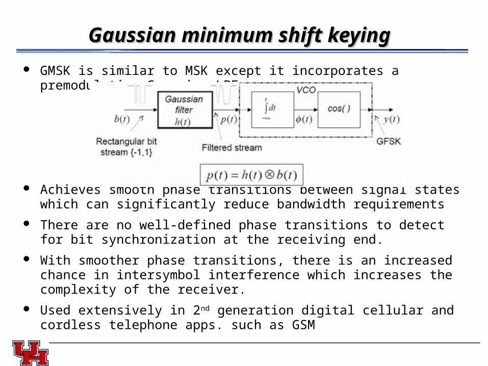
Gaussian minimum shift keying Gaussian minimum shift keying
GMSK is similar to MSK except it incorporates a premodulation Gaussian LPF
Achieves smooth phase transitions between signal states which can significantly reduce bandwidth requirements
There are no well-defined phase transitions to detect for bit synchronization at the receiving end.
With smoother phase transitions, there is an increased chance in intersymbol interference which increases the complexity of the receiver.
Used extensively in 2nd generation digital cellular and cordless telephone apps. such as GSM