Embed Size (px)
Citation preview
ECE 320 - Homework #8
Boolean Logic, DTL, TTL Logic. Due Monday, Marth 8th
Boolean Logic
1) Implement the following funciton using NAND gates (i.e. circle the ones)
f(A,B,C,D) CD
00 01 11 10
AB
00 1 0 0 0
01 1 1 0 1
11 x x x x
10 1 1 x x
Y = A + C'D' + BC' + BD'
Y
D'
B
C'
B
D'
C
A
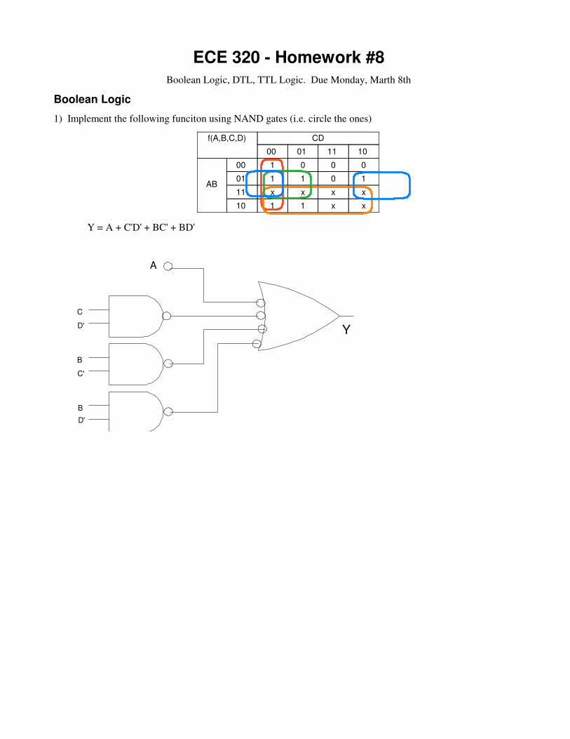
2) Implement the following function using NOR gates (i.e. circle the zeros)
f(A,B,C,D) CD
00 01 11 10
AB
00 1 0 0 0
01 1 1 0 1
11 x x x x
10 1 1 x x
Y' = CD + A'B'D + A'B'C
Y = (C' + D')(A + B + D') (A + B + C')
Y
C'
D'
A
D'
NOR
NOR NOR
A
C'
NOR
B
B
DTL Logic
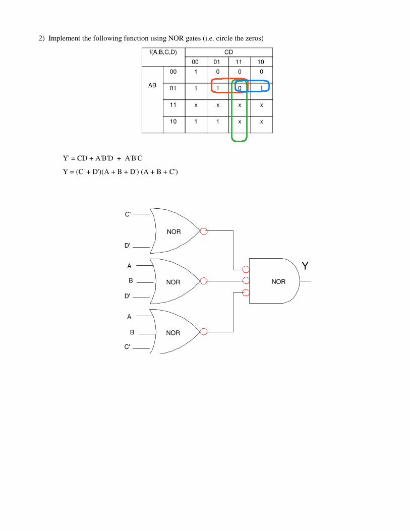
3) Determine the voltages and currents for the following DTL OR gate
5V
5V
0V
1k
20k
1k
5V
20k 20kV1
I2
V3
I4
V5
4.3V
0.7V
0.2V4.76V
sat off
180uA 0mA
238uA4.8mA
T1 T2
The 5V source turns on transistor T1 (saturated)
I2 =
5V−0.7V−0.7V
20k
= 180µA
T1 is saturatedβI2 = 18mA > 4.8mA
0.2V at V3 isn't enough to turn on T2 (off)
V5 =
20k
20k+1k
5V = 4.76V
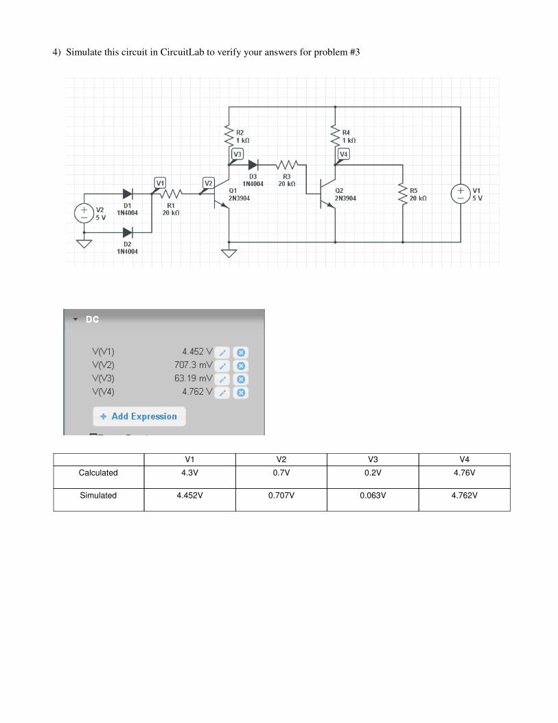
4) Simulate this circuit in CircuitLab to verify your answers for problem #3
V1 V2 V3 V4
Calculated 4.3V 0.7V 0.2V 4.76V
Simulated 4.452V 0.707V 0.063V 4.762V
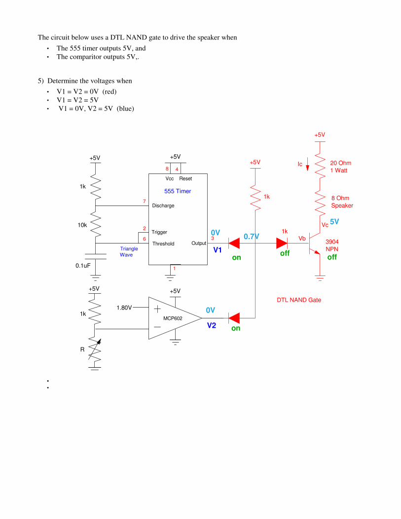
The circuit below uses a DTL NAND gate to drive the speaker when
The 555 timer outputs 5V, and
The comparitor outputs 5V,.
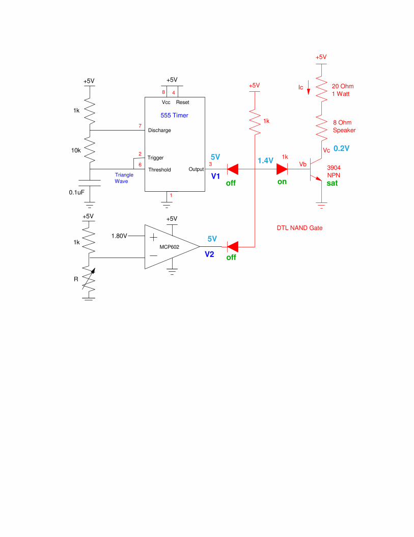
5) Determine the voltages when
V1 = V2 = 0V (red)
V1 = V2 = 5V
V1 = 0V, V2 = 5V (blue)
1k
10k
0.1uF
+5V +5V
555 Timer
Vcc Reset
Discharge
Trigger
Threshold Output
1
8 4
2
6
7
3
Triangle
Wave
8 Ohm
Speaker
20 Ohm
1 Watt
+5V
1k
3904
NPN
Vb
Vc
Ic
MCP602
1.80V
+5V +5V
1k
R
+5V
1k
DTL NAND Gate
V1
V2
0V
0V
0.7V
5V
on
on
offoff
1k
10k
0.1uF
+5V +5V
555 Timer
Vcc Reset
Discharge
Trigger
Threshold Output
1
8 4
2
6
7
3
Triangle
Wave
8 Ohm
Speaker
20 Ohm
1 Watt
+5V
1k
3904
NPN
Vb
Vc
Ic
MCP602
1.80V
+5V +5V
1k
R
+5V
1k
DTL NAND Gate
V1
V2
5V
5V
1.4V
0.2V
off
off
on sat
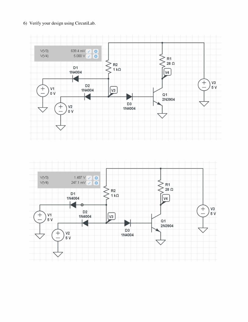
6) Verify your design using CircutiLab.

Lab: 7) (20pt): Verify your design in hardware (build and test the circuit with your lab kit).
1k
10k
0.1uF
+5V +5V
555 Timer
Vcc Reset
Discharge
Trigger
Threshold Output
1
8 4
2
6
7
3
Triangle
Wave
8 Ohm
Speaker
20 Ohm
1 Watt
+5V
1k
3904
NPN
Vb
Vc
Ic
MCP602
1.80V
+5V +5V
1k
R
+5V
1k
DTL NAND Gate
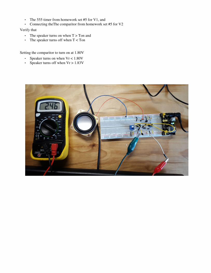
The 555 timer from homework set #5 for V1, and
Connecting theThe comparitor from homework set #5 for V2
Verify that
The speaker turns on when T > Ton and
The speaker turns off when T < Ton
Setting the comparitor to turn on at 1.80V
Speaker turns on when Vr < 1.80V
Speaker turns off when Vr > 1.83V
TTL Logic
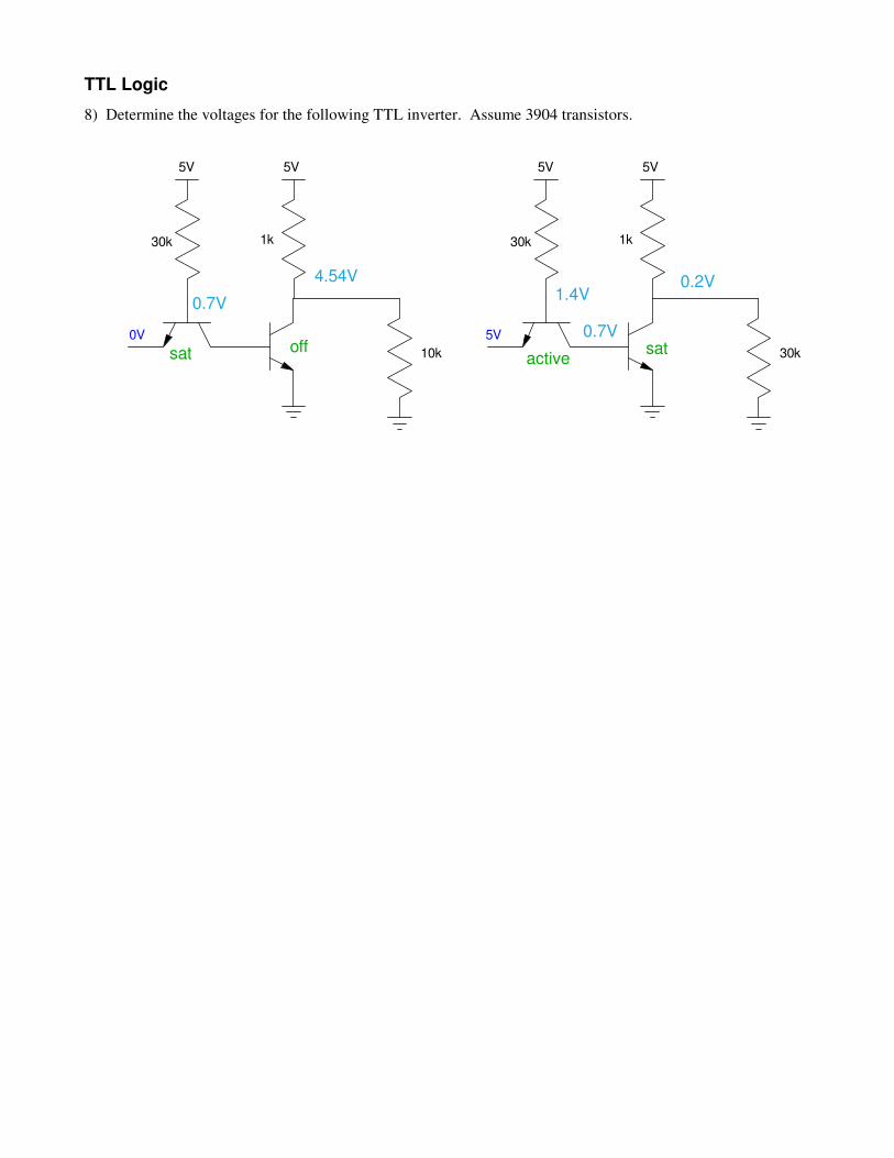
8) Determine the voltages for the following TTL inverter. Assume 3904 transistors.
5V 5V
1k
10k
30k
5V 5V
1k
30k
30k
0V 5V
0.7V
4.54V
0.7V
1.4V0.2V
satoffsat active
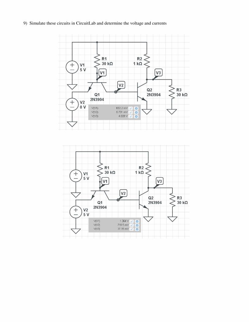
9) Simulate these circuits in CircuitLab and determine the voltage and currents