Embed Size (px)
Citation preview
ECE 300 Microprocessor Project Nick JonesNick Jones
Bibi MoralesBibi Morales
Hadi ChoueiryHadi Choueiry
Tyler GriffinTyler Griffin
Group 9
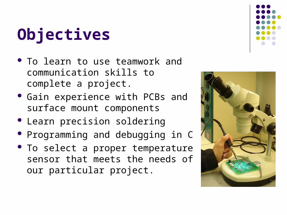
Objectives
To learn to use teamwork and communication skills to complete a project.
Gain experience with PCBs and surface mount components
Learn precision soldering Programming and debugging in C To select a proper temperature
sensor that meets the needs of our particular project.

Board Components - Chip
The first component that was soldered onto the board was the MSP430 chip using the provided microscope.
This was done by aligning the chip with the circuit traces and keeping it stable with a tiny bit of flux.
There were 100 solder connections which proved to be difficult at first.
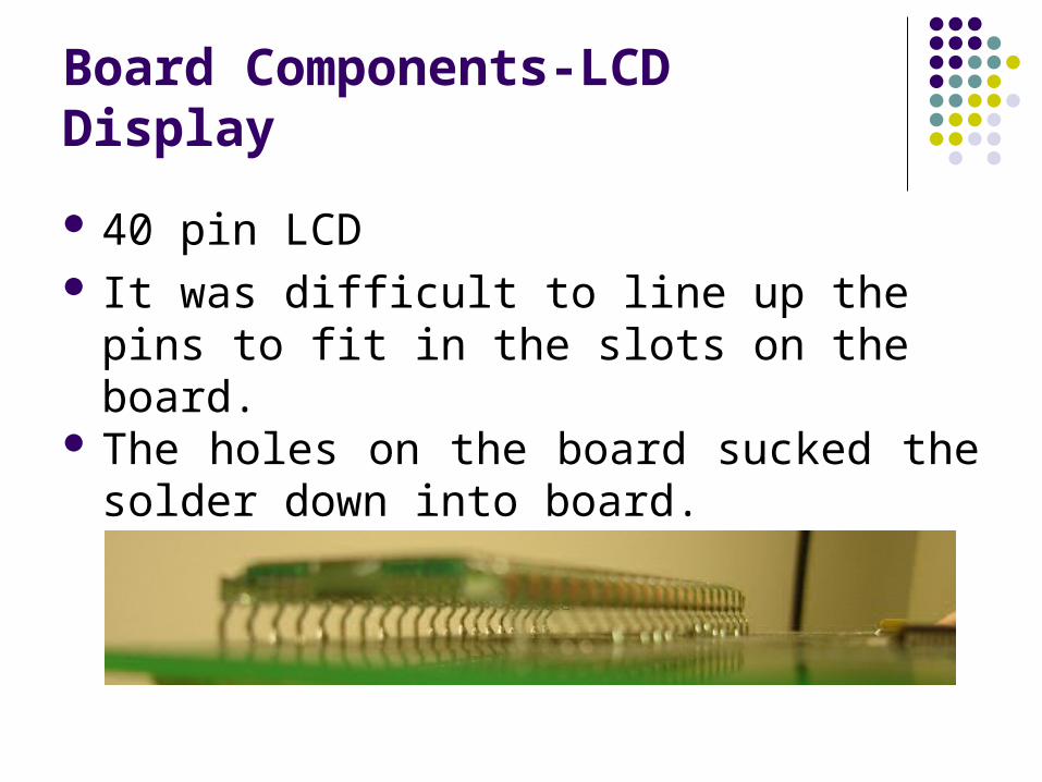
Board Components-LCD Display
40 pin LCD It was difficult to line up the pins to fit in the
slots on the board. The holes on the board sucked the solder
down into board.
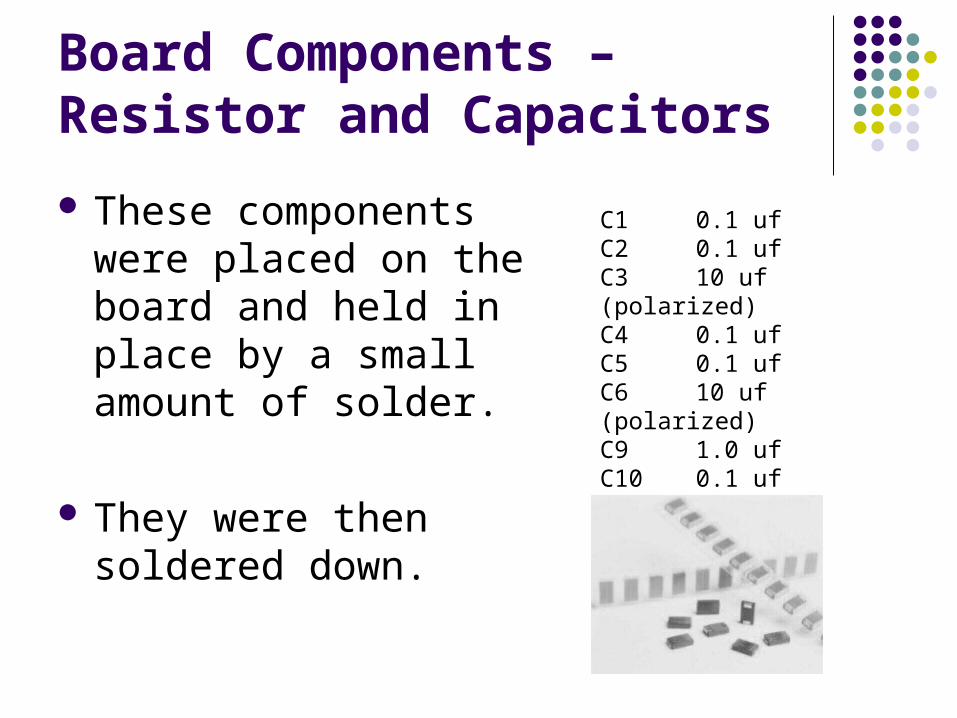
Board Components – Resistor and Capacitors
These components were placed on the board and held in place by a small amount of solder.
They were then soldered down.
C1 0.1 uf C2 0.1 uf C3 10 uf (polarized) C4 0.1 uf C5 0.1 uf C6 10 uf (polarized) C9 1.0 uf C10 0.1 uf R5 47 kohms
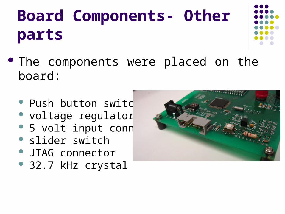
Board Components- Other parts
The components were placed on the board:
Push button switch voltage regulator 5 volt input connector slider switch JTAG connector 32.7 kHz crystal
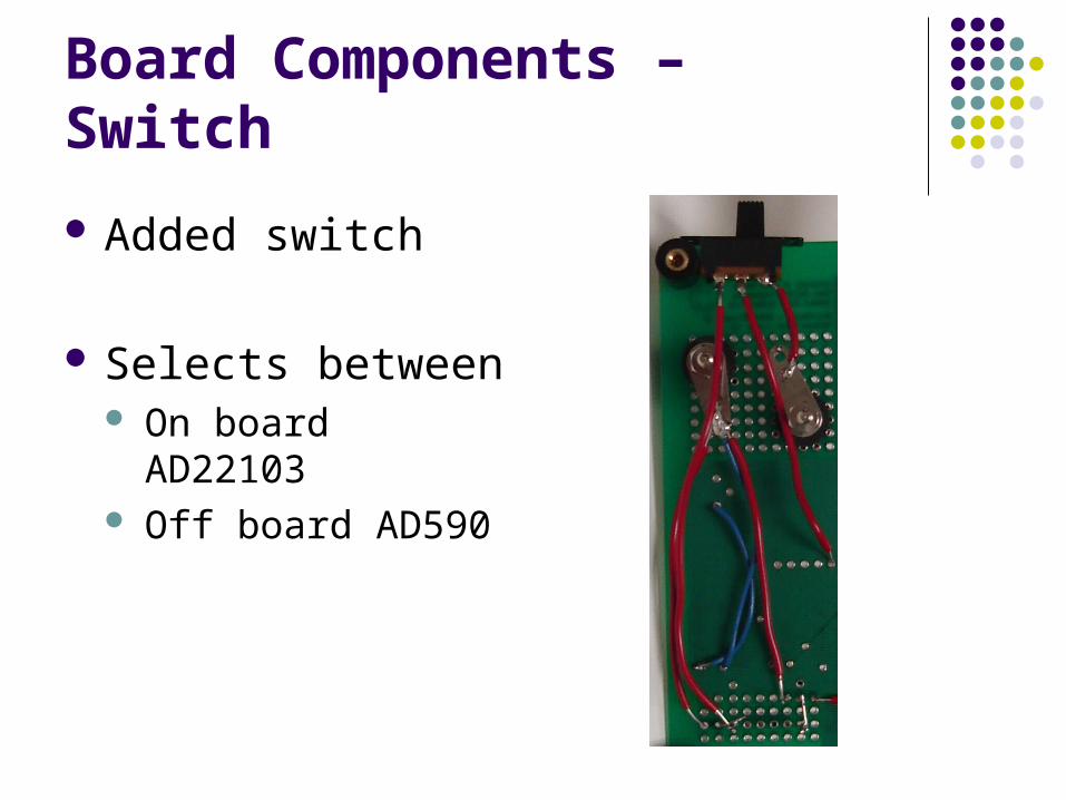
Board Components – Switch
Added switch
Selects between On board AD22103 Off board AD590
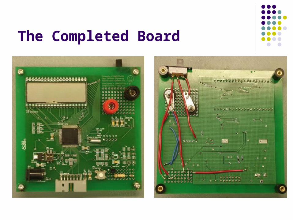
The Completed Board
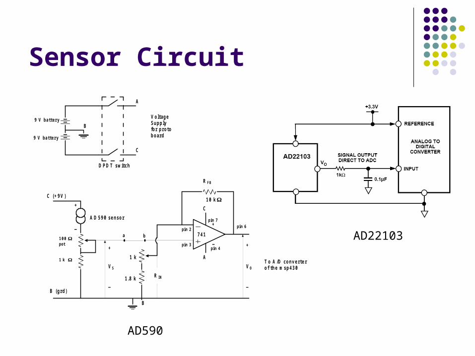
Sensor Circuit
9 V ba t te ry
9 V ba t te ry
B
A
C
D P D T s w itc h
V o ltag eS u p p lyfo r p ro tob o ard
C (+ 9 V )
B (g rd )
+
_
A D 5 9 0 s e n s o r
7 4 1
B
pin 7
pin 4
pin 6pin 2
pin 3
C
A
+
_+
_
V S
R FB
R IN
1 0 k
1 .8 k
1 k
+
_
V O
T o A /D c o n v e rte ro f th e m s p 4 3 0
• •a b
1 0 0 pot
1 k
AD590
AD22103
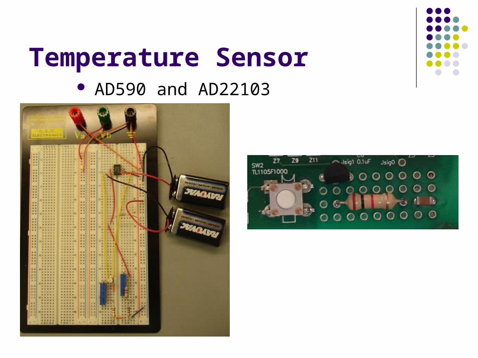
Temperature Sensor AD590 and AD22103
Programming the Chip
The files provided by Dr. Green, lcd.c, lcd.h, delay.c, delay.h, demo.c, sensor.c, were used in our project.
The MSP430 Flash emulation tool was connected to the board and the computer.
Using IAR and C-SPY we programmed the board.
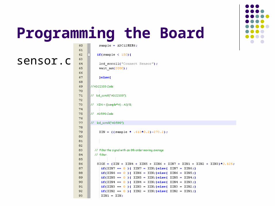
Programming the Board
sensor.c
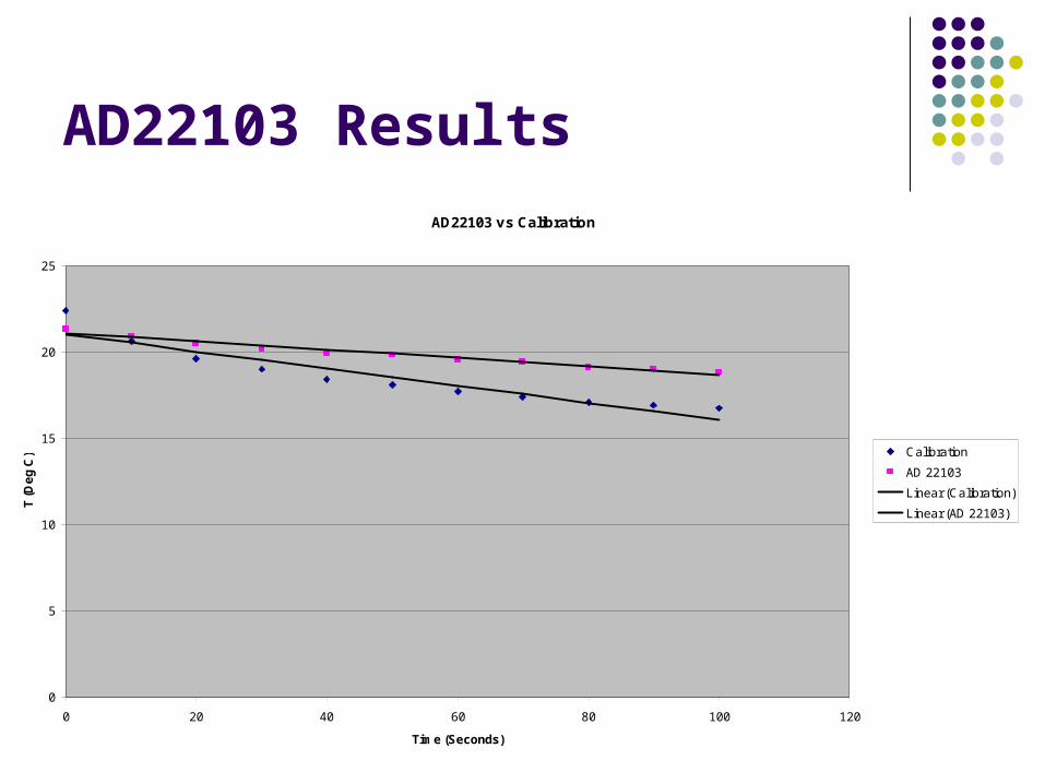
AD22103 Results
AD22103 vs Calibration
0
5
10
15
20
25
0 20 40 60 80 100 120
Time (Seconds)
T (
De
g C
) Calibration
AD 22103
Linear (Calibration)
Linear (AD 22103)
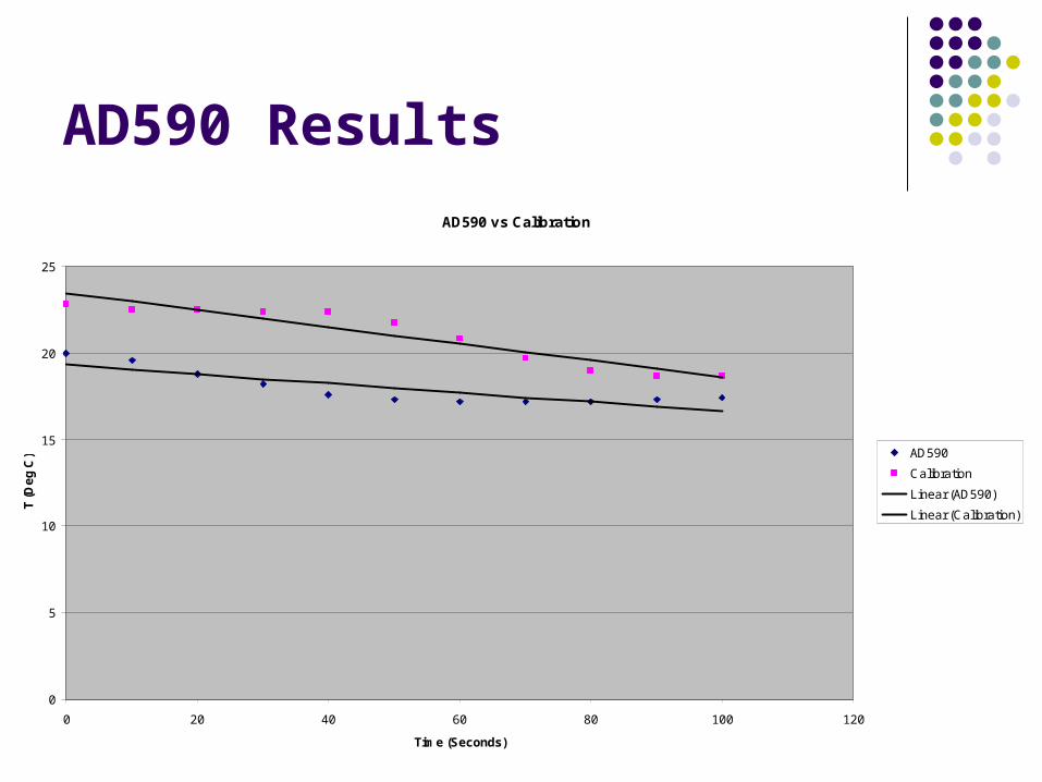
AD590 Results
AD590 vs Calibration
0
5
10
15
20
25
0 20 40 60 80 100 120
Time (Seconds)
T (
De
g C
) AD590
Calibration
Linear (AD590)
Linear (Calibration)
Questions?
Nick JonesNick Jones
Bibi MoralesBibi Morales
Hadi ChoueiryHadi Choueiry
Tyler GriffinTyler Griffin
Group 9
![[XLS]cbsialkot.gov.pkcbsialkot.gov.pk/allforms/Sadar Bazar Areas.xls · Web viewNAWAB DIN 1/3 SHARE FATIMA BIBI MUHAMMAD SADDIQ SAKINA BIBI SUGHRA BIBI MUHAMMAD RAFIQ 1/3 SHARE MST](https://img.pdfslide.us/doc/110x75/5afdc9707f8b9aa34d8df75b/xls-bazar-areasxlsweb-viewnawab-din-13-share-fatima-bibi-muhammad-saddiq-sakina.jpg)