Embed Size (px)
Citation preview

1
8-bit Booth Multiplier
Eric Wang
Federico Gonzalez
Bryan Flemming
Jep Barbour
ECE 261 Project Presentation 2

Abstract
The purpose of this project is to create a 8 by 8 multiplier using Booth’s multiplication algorithm. The 8-bit multiplicand and 8-bit multiplier are input signals into four Booth encoders/selectors. After applying Booth’s algorithm to the inputs, simple addition is done to produce a final output.
Our main goal is to produce a working 8 by 8 bit multiplier with correct simulations and layout while attempting to maximize the speed in which the multiplier performs the calculation.2

3
8 Bit Multiplicand
8 B
it Mu
ltiplier
Booth Encoder/ Selector for bits [0 1 2]
Booth Encoder/ Selector for bits [4 5 6]
Booth Encoder/ Selector for bits [2 3 4]
Booth Encoder/ Selector for bits [6 7 8]
16 Bit Carry Save Adder
16 Bit Carry
Save Adder
16 Bit Carry
Save Adder
Product Out
Schematic Block Diagram

Booth Encoder
Schematic

Booth Encoder

Booth DecoderSchematic

Booth DecoderLayout
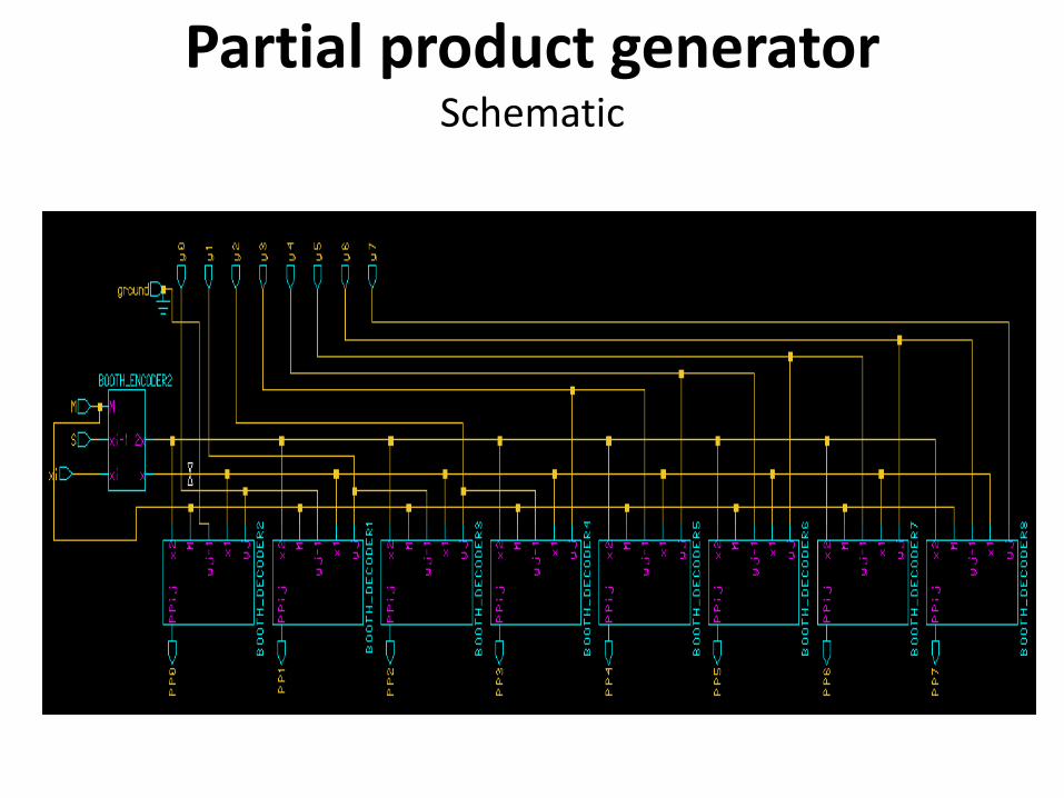
Partial product generatorSchematic

Partial product generator
Booth Encoder
8 Booth Decoders

Full Adder
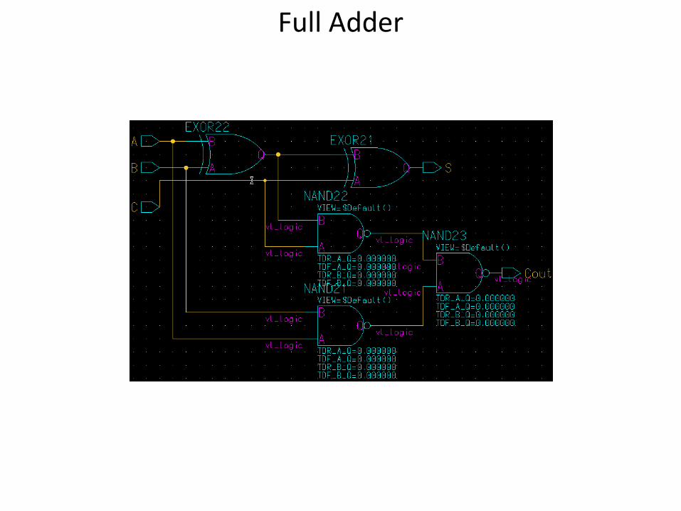
Full Adder

16 bit Carry Save Adder

CSA16
16 bit Carry Save Adder

CSA16
4 bit Carry Save Adder

CSA16
4 bit Carry Save Adder

Top Level Diagram

Top Level Layout

Functional Simulations
• Our Eldo would not simulate the top level diagram with all three adders included
• Therefore, for simulations, we deleted the third adder, and took the outputs at the ends of the inner adders.
• To verify functionality through simulation, we simply took the two outputs we found and added them ourselves.

Test 1:
• Multiplier input: 00001010 = 10
• Multiplicand input: 00000101 = 5
• Output 1: 1111111111011110
• Output 2: 0000000001010100
• Sum of outputs: 0000000000110010 = 50
• As we can see, the output equals the product of the two inputs

Test 2
• Multiplier input: 01011101 = 93
• Multiplicand input: 0001101010 = 26
• Output 1: 1111111110100110
• Output 2: 0000100111000100
• Sum of outputs: 0000100101101010 = 2418
• Once again the final output is equal to the product of the inputs as expected.

Timing Simulations
• Propagation time? Only 6ns worst case

Propagation Time continued
• Extra adder! 2ns additional propagation time.

Power Consumption
• Simulation of top level block (minus the final adder of course) showed an average power consumption of 73.72 nano Watts.
• Simulation of the adder gave a power consumption of 21.24 nW.
• Therefore the total power consumption of our circuit is expected to be an average of 94.96nW.