Embed Size (px)
Citation preview

1
ECE 2054
Using the Digital Multimeter

2
WARNING! Static discharge
can destroy your meter.
In dry conditions, even moving in your chair can create a large charge of static electricity on you. Always ground yourself to something (e.g. touch something metal) before opening the meter case.
The ECE department is not responsible for meters damaged by abuse or static discharge.
If you have any doubts about your ability to perform this procedure, consult with an OpEL GTA.

3
Meter Leads
Your LiaB kit has several types of leads.
Left to right are:
• Probe
• IC-hook or mini-grabber
• Alligator clip
• The probe is good for measuring
devices with terminals, but be careful
on a breadboard because it is easy to
create a short circuit between
component leads with a probe tip.

4
• The IC-hook / mini-grabber is
useful for attaching to
component leads and wires.
• The Alligator clip is useful for
attaching to wires, larger parts,
and ground connections.
Clipping an Alligator to a small
terminal, as shown in the photo
on the right, is asking for
trouble.

Connecting Leads to the Multimeter
• The meter uses “Banana Jacks” for lead connections – insert the banana plugs into the appropriate meter jacks.
• COM (black arrow) is the common or ground lead used as a reference for all measurements.
• VΩHz (red arrow) is used to measure voltages, resistance, and frequency.
• 10A (blue arrow)is used for high current AC and DC measurements.
• mA (yellow arrow) is used for low current AC and DC measurements. Caution: Fused at 200mA!
5

Meter Tip for easier scale setting
The range switch has a notch in
the end of the knob to show the
chosen scale. This notch is difficult
to see in poor lighting.
The range position is much
easier to see if you fill the notch
with paint or whiteout.
6

Resistance Measurement
1. The red cable Banana plug is inserted
into the “VΩHz” jack of the multimeter.
2. The black cable Banana plug is put
into the “COM” (ground) jack of the
multimeter.
3. Clip the leads to a resistor.
7

Resistance Range
4. Adjust the Ω range switch for best
resolution.
• For ANY meter measurement, adjust
the range for maximum resolution
without an overflow.
8

Measuring a Resistor Value1. Clip the meter leads to the 100Ω resistor.
Adjust the meter for maximum accuracy,
and write the range setting and measured
resistance on Part A of the worksheet.
2. Replace the 100Ω resistor with the 10kΩ
resistor. Adjust the meter for maximum
accuracy, and write the range setting and
measured resistance on Part A of the
worksheet.
• You may (just for fun) measure the
resistance of your body between
your two hands (one lead in each
hand). Try different scales, try it
dry, try it wet.
9

10
DC Voltage Measurement
• The red cable is inserted into the “VΩHz” jack.
• The black cable is put into the “COM”
(ground) jack.
• The meter range switch is turned to one of the
DC volts settings.
• The other end of the cables may be used
directly on the circuit (with caution) or you can
add short lengths of wire to the IC-clip or
Alligator to assist with the measurement.
• Voltage measurements are made by placing
the meter leads across (in parallel with) a
component or from one point on a circuit
another point on a circuit.

Measure the voltage of your old battery
1. Set the meter to measure DC Volts. It is
best to set the range above the expected
voltage
2. Use the probes or clips with wires to touch
the battery terminals. The positive (+)
battery terminal is the smaller (male)
terminal.
3. Adjust the meter range for best resolution.
Record your measurement on Part B of
the worksheet.
4. Swap the lead connections and notice
how the meter reads negative voltage
when the leads are reversed.
11

DC Current Measurement – very tricky!1. The red cable is inserted into the 10A jack (set
the meter switch to measure 10A DC) or into
the mA jack (set the meter switch to measure
2m, 20m, or 200m DC).CAUTION: the current shunt acts as a short circuit. It
is very easy to blow the mA fuse if you connect the
meter leads to a circuit incorrectly.
2. The black cable is put into the COM (ground)
jack.
3. For polarity, positive current flows into the red
lead and back out of the black Common lead.
4. Measurements are made by placing the meter
leads in series with a component (move a
component lead to open the circuit, and use
the meter leads to complete the circuit).12

To measure an unknown current
1. Always measure with the 10A scale first!
– This reduces the chance of blowing the mA fuse.
2. Make sure that you have the scale set to
10A DC and the lead in the 10A jack.
– If you fail to do this, the meter will display 0 even if
there is a large current flowing!
3. If your measured current is less than 0.2A,
change the range to 200m and move the
red lead to the mA jack. Adjust the range for
maximum resolution.
4. After the current measurement is
complete, always move the red lead back
to “VΩHz”. This is easy to forget!
13

Current measurement accuracy (AC and DC)
From the owners manual and the Specification Sheet:
• For polarity, positive current flows into the red lead and back out of
the black Common lead.
14
Range Resolution Accuracy Burden
Voltage
2mA 1μA +/-0.8% of reading ± 1 digits 110mV/mA
20mA 10μA +/-0.8% of reading ± 1 digit 15mV/mA
200mA 100μA +/-1.5% of reading ± 1 digit 5mV/mA
10A 10mA +/-2.0% of reading ± 5 digits 0.03V/A
The Burden Voltage is the voltage drop across the shunt.
For example, a 10mA current with the meter set to the 20mA
scale, will produce a 300mV drop between the red and black leads
(20mA X 15mV/mA = 300mV). This drop can significantly affect measurements of low voltage circuits.

15
ANDY Board current measurement
1. Begin with your original circuit (upper photo).
2. Lift one end of a component and move the
lead to a new column (lower photo).
3. Connect the red meter lead (plugged into the
10A jack) into the column to the component’s
moved end (lower photo).
4. Connect the black meter lead to the original
column where the component’s end was
before you moved it. (lower photo)
• You have now opened the circuit and re-
completed it by inserting the meter in series
with the resistor.
4. Set the meter scale to 10A, power up the
ANDY board and read the current. It should
be low for most circuits.

Larger image of measurement connection
• If your measurement is greater
than 0.2A, do not use the mA
scale.
5. If the 10A range measurement
is less than 0.2A, move the red
lead to the mA jack on the
meter, and adjust the range for
maximum resolution.
16

How you can get into trouble….
• The DMM’s ammeter is nothing more than a very low value resistor
with a voltmeter connected across the resistor. As current flows
through the resistor, a voltage drop proportional to the current is
created (Ohm’s Law). The meter converts this measured voltage to
a current value for the display.
• On the 10A scale, the resistor is a piece of wire.
• On the mA scales, the resistor is smaller and protected by a 200mA
fuse.
17
18
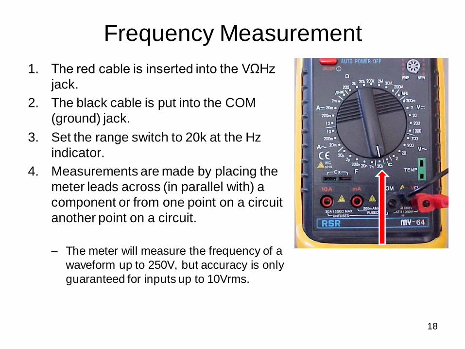
Frequency Measurement
1. The red cable is inserted into the VΩHz
jack.
2. The black cable is put into the COM
(ground) jack.
3. Set the range switch to 20k at the Hz
indicator.
4. Measurements are made by placing the
meter leads across (in parallel with) a
component or from one point on a circuit
another point on a circuit.
– The meter will measure the frequency of a
waveform up to 250V, but accuracy is only
guaranteed for inputs up to 10Vrms.

AC Voltage Measurement
• The red cable is inserted into the “VΩHz”
jack.
• The black cable is put into the “COM”
(ground) jack.
• The range switch is turned to somewhere
in the AC volts group (AC volts appears as
V~ on the meter).
• Voltage measurements are made by
placing the meter leads across (in parallel
with) a component or from one point on a
circuit another point on a circuit.
19

AC Current Measurement – also tricky!1. The red cable is inserted into the 10A jack (set
the meter switch to measure 10A AC) or into
the mA jack (set the meter switch to measure
2m, 20m, or 200m AC).CAUTION: As with DC current, the AC current shunt
acts as a short circuit.
2. The black cable is put into the COM (ground)
jack.
3. Measurements are made by placing the meter
leads in series with a component (move a
component lead to open the circuit, and use
the meter leads to complete the circuit).
20

21
ANDY Board AC current measurement
1. Begin with your +9V measurement circuit.
2. Lift the negative lead of the resistor and move
the lead to a new column (photo next sheet).
3. Insert the meter red lead (plugged into the
10A jack) into the column with the moved
resistor end.
• You have now opened the circuit and re-
completed it by inserting the meter in series
with the resistor.
• Leave the black COM lead connected to black
wire from the GND block.
4. Set the meter scale to 10A, power up the
ANDY board and read the current. It should
be near 0A.

Larger image of measurement connection
• If your measurement is greater
than 0.01A, troubleshoot your
wiring.
5. When the 10A range
measurement is near 0A,
move the red lead to the mA
jack on the meter, and adjust
the range for maximum
resolution. Complete Part F on
the worksheet.
22