Embed Size (px)
Citation preview


DSBA3300 - Révision 10-01-2017 3/15
ECD.1A - ECM.1 & .2 - DESCRIPTION ECD.1A - ECM.1 & .2 - DESCRIPTION
ECD.1A - ECM.1 & .2 - BESCHREIBUNG ECD.1A - ECM.1 & .2 - DESCRIPCIÓN
EN D ES
Type : ECM Type : ECD ER seulement ER only ER nur ER solamente
ECD.1A ECM.1 ECM.2
Connecteur 3P+T DIN43650. 3P+T DIN43650 connector. Gerätesteckdose nach DIN43650 3P+T Conectador DIN43650 3P+T
1 x Connecteur M12. 1 x M12 connector. 1 x Gerätesteckdose nach M12 1 x Conectador M12
2 x Connecteur M12. 2 x M12 connector. 2 x Gerätesteckdose nach M12 2 x Conectador M12
IP66 IP67 IP67
MONTAGE ET ENCOMBREMENTS (ECD.1A) / ASSEMBLY AND DIMENSIONS (ECD.1A) EINBAU UND DIMENSIONEN (ECD.1A) / MONTAJE Y DIMENCIONES (ECD.1A)
Nos presse-étoupe acceptent un câble de diamètre compris entre 7mm et 12mm. Our cable glands are designed for cables with a diameter between 7mm and 12mm. Unsere Kabelverschraubungen sind zulässig für Kabel mit einem Durchmesser zwischen 7mm und 12mm. Nuestros prensas a estopa aceptan un cable de diámetro entre 7mm y 12mm.
Prévoir un shunt entre 4 et 6 (côté câblage client) Foresee a shunt between 4 and 6 (customer wiring) Nebenschluss zwischen 4 und 6 vorsehen (Verkabelung des Benutzers) Prever un shunt entre 4 y 6 (cableado cliente)

4/15 DSBA3300 - Révision 10-01-2017
ECD.1A - SCHÉMA ÉLECTRIQUE
EN D
ES
ECD.1A - ELECTRIC WIRING
ECD.1A - SCHALTPLAN ECD.1A - ESQUEMA ELÉCTRICO
REP DESIGNATION / BESCHREIBUNG / DESIGNACIÓN
FC0 Fin de course ouverture Open limit switch Endschalter AUF Final de carrera apertura
FC1 Fin de course auxiliaire 1 Auxiliary limit switch 1 Zusätzlicher Endschalter 1 Final de carrera auxiliar 1
D1/D2 Bornier report défaut (24V DC / 3A max) (ER PLUS) Failure report Terminal strip (24V DC / 3A max) (ER PLUS) Fehlermeldung Klemmleiste (24V DC / 3A max) (ER PLUS) Terminal retorno de defecto (24V DC / 3A max) (ER PLUS)
FCF Fin de course fermeture Close limit switch Endschalter ZU Final de carrera cierre
FC2 Fin de course auxiliaire 2 Auxiliary limit switch 2 Zusätzlicher Endschalter 2 Final de carrera auxiliar 2
M Moteur Motor
N -
Ouvrir Open Auf
Abrir
Fermer Close
Zu Cerrar
Ph +
N -
Ouvrir Open Auf
Abrir
Ph +
Mode 3 points modulants 3-points modulating mode
3-Punkt-Modus Modo 3 puntos modulantes
Mode Tout ou rien (ON/OFF) On-Off mode On-Off Modus
Modo Todo o nada (ON-OFF),
ALIMENTATION / POWER SUPPLY / SPANNUNGSVERSORGUNG / ALIMENTACIÓN (Connecteur noir / black connector / Schwartz Verbindung / conectador negro)
TP/PE
2 3
1 2 3
1
TP/PE
FC
F
FC
0
A
B
+ —
~
~
FC
2
FC
1
A
3 2 1
15V-30V 50/60Hz (12V-48V DC) 100V-240V 50/60Hz (100V-350V DC)
C
M
1 2 3
18 17
Version Failsafe
(ER PLUS)
Mode ON/OFF obligatoire ON/OFF mode compulsory ON/OFF Modus notwendig
Modo ON/OFF oblgatorio
TP/PE
9 8 7 5
D2
D1
6 4
1 2 3
CO
MM
UN
FC
1/F
C2
CO
MM
ON
G
EM
EIN
SA
M
CO
MÚ
N
RE
CO
PIE
FC
1
FE
ED
BA
CK
R
ÜC
KM
ELD
UN
G
RE
CO
PIA
RE
CO
PIE
FC
2
FE
ED
BA
CK
R
ÜC
KM
ELD
UN
G
RE
CO
PIA
RECOPIE / FEEDBACK / RÜCKMELDUNG / RECO-PIA
(Connecteur gris / grey connector grau Verbin- dung / conec-tador gris )
1 2 3
ECD.1A
CABLAGE CLIENT SUGGERE / SUGGESTED CUSTOMER WIRING / EMPFOHLENE VERDRAHTUNG / CABLEADO SUGERIDO CLIENTE
ECD.1A
DSBA3300 - Révision 10-01-2017 5/15
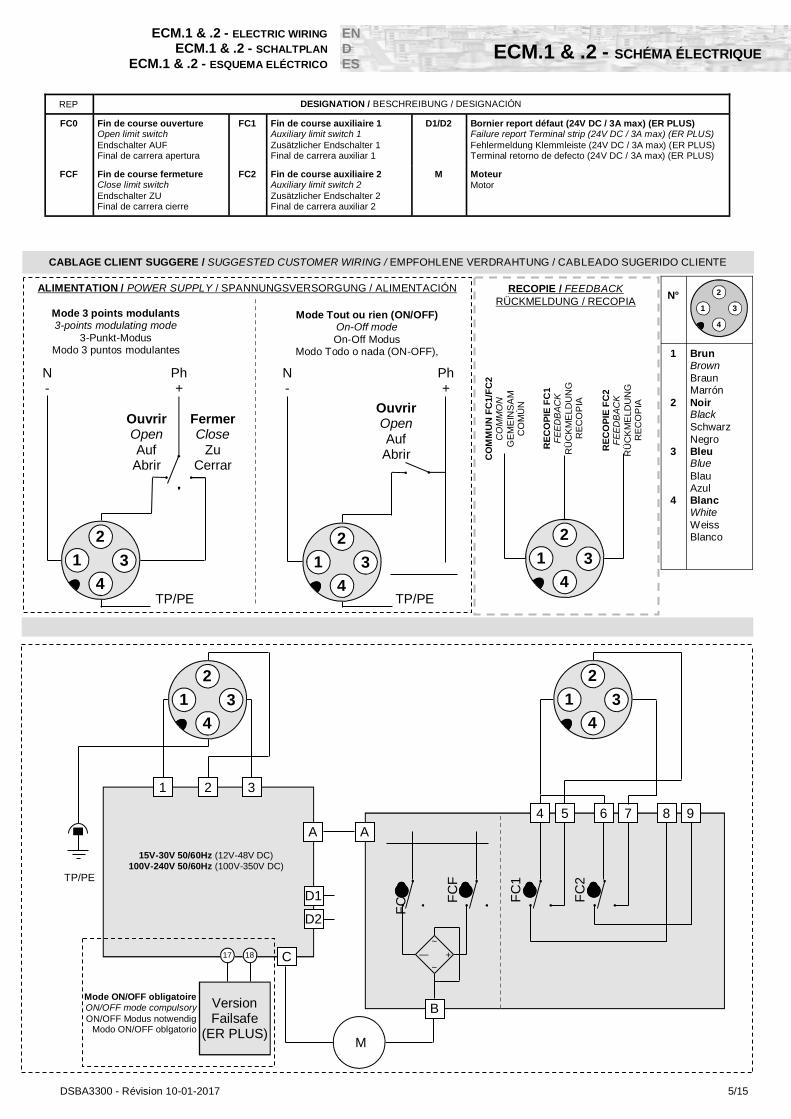
ECM.1 & .2 - SCHÉMA ÉLECTRIQUE
ECM.1 & .2 - ELECTRIC WIRING
ECM.1 & .2 - SCHALTPLAN ECM.1 & .2 - ESQUEMA ELÉCTRICO
EN D ES
N°
1 2 3 4
Brun Brown Braun Marrón Noir Black Schwarz Negro Bleu Blue Blau Azul Blanc White Weiss Blanco
1
2
3
4
FC
F
FC
0
A
B
+ —
~
~
FC
2
FC
1
A
15V-30V 50/60Hz (12V-48V DC) 100V-240V 50/60Hz (100V-350V DC)
C
M
18 17
Version Failsafe
(ER PLUS)
Mode ON/OFF obligatoire ON/OFF mode compulsory ON/OFF Modus notwendig
Modo ON/OFF oblgatorio
TP/PE
9 8 7 5
D2
D1
6 4
N -
Ouvrir Open Auf
Abrir
Fermer Close
Zu Cerrar
Ph +
N -
Ouvrir Open Auf
Abrir
Ph +
Mode 3 points modulants 3-points modulating mode
3-Punkt-Modus Modo 3 puntos modulantes
Mode Tout ou rien (ON/OFF) On-Off mode On-Off Modus
Modo Todo o nada (ON-OFF),
ALIMENTATION / POWER SUPPLY / SPANNUNGSVERSORGUNG / ALIMENTACIÓN
CO
MM
UN
FC
1/F
C2
CO
MM
ON
G
EM
EIN
SA
M
CO
MÚ
N
RE
CO
PIE
FC
2
FE
ED
BA
CK
R
ÜC
KM
ELD
UN
G
RE
CO
PIA
RE
CO
PIE
FC
1
FE
ED
BA
CK
R
ÜC
KM
ELD
UN
G
RE
CO
PIA
RECOPIE / FEEDBACK RÜCKMELDUNG / RECOPIA
CABLAGE CLIENT SUGGERE / SUGGESTED CUSTOMER WIRING / EMPFOHLENE VERDRAHTUNG / CABLEADO SUGERIDO CLIENTE
2
1 3
4
1 2 3
2
1 3
4
2
1 3
4
2
1 3
4
2
1 3
4
REP DESIGNATION / BESCHREIBUNG / DESIGNACIÓN
FC0 Fin de course ouverture Open limit switch Endschalter AUF Final de carrera apertura
FC1 Fin de course auxiliaire 1 Auxiliary limit switch 1 Zusätzlicher Endschalter 1 Final de carrera auxiliar 1
D1/D2 Bornier report défaut (24V DC / 3A max) (ER PLUS) Failure report Terminal strip (24V DC / 3A max) (ER PLUS) Fehlermeldung Klemmleiste (24V DC / 3A max) (ER PLUS) Terminal retorno de defecto (24V DC / 3A max) (ER PLUS)
FCF Fin de course fermeture Close limit switch Endschalter ZU Final de carrera cierre
FC2 Fin de course auxiliaire 2 Auxiliary limit switch 2 Zusätzlicher Endschalter 2 Final de carrera auxiliar 2
M Moteur Motor
TP/PE TP/PE
6/15 DSBA3300 - Révision 10-01-2017
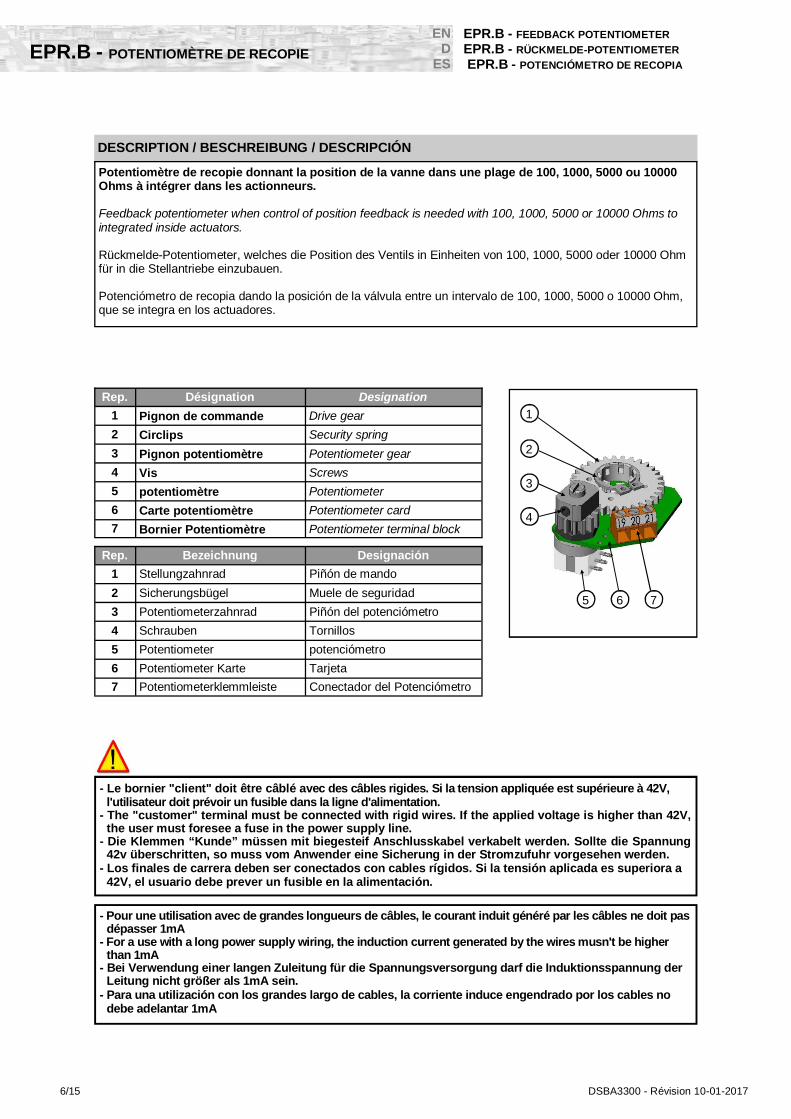
EPR.B - POTENTIOMÈTRE DE RECOPIE
EN D
ES
EPR.B - FEEDBACK POTENTIOMETER
EPR.B - RÜCKMELDE-POTENTIOMETER EPR.B - POTENCIÓMETRO DE RECOPIA
Rep. Désignation Designation
1 Pignon de commande Drive gear
2 Circlips Security spring
3 Pignon potentiomètre Potentiometer gear
4 Vis Screws
5 potentiomètre Potentiometer
6 Carte potentiomètre Potentiometer card
7 Bornier Potentiomètre Potentiometer terminal block
- Le bornier "client" doit être câblé avec des câbles rigides. Si la tension appliquée est supérieure à 42V, l'utilisateur doit prévoir un fusible dans la ligne d'alimentation.
- The "customer" terminal must be connected with rigid wires. If the applied voltage is higher than 42V, the user must foresee a fuse in the power supply line.
- Die Klemmen “Kunde” müssen mit biegesteif Anschlusskabel verkabelt werden. Sollte die Spannung 42v überschritten, so muss vom Anwender eine Sicherung in der Stromzufuhr vorgesehen werden.
- Los finales de carrera deben ser conectados con cables rígidos. Si la tensión aplicada es superiora a 42V, el usuario debe prever un fusible en la alimentación.
DESCRIPTION / BESCHREIBUNG / DESCRIPCIÓN
Potentiomètre de recopie donnant la position de la vanne dans une plage de 100, 1000, 5000 ou 10000 Ohms à intégrer dans les actionneurs. Feedback potentiometer when control of position feedback is needed with 100, 1000, 5000 or 10000 Ohms to integrated inside actuators. Rückmelde-Potentiometer, welches die Position des Ventils in Einheiten von 100, 1000, 5000 oder 10000 Ohm für in die Stellantriebe einzubauen. Potenciómetro de recopia dando la posición de la válvula entre un intervalo de 100, 1000, 5000 o 10000 Ohm, que se integra en los actuadores.
Rep. Bezeichnung Designación
1 Stellungzahnrad Piñón de mando
2 Sicherungsbügel Muele de seguridad
3 Potentiometerzahnrad Piñón del potenciómetro
4 Schrauben Tornillos
5 Potentiometer potenciómetro
6 Potentiometer Karte Tarjeta
7 Potentiometerklemmleiste Conectador del Potenciómetro
2
3
7
4
5 6
1
- Pour une utilisation avec de grandes longueurs de câbles, le courant induit généré par les câbles ne doit pas dépasser 1mA
- For a use with a long power supply wiring, the induction current generated by the wires musn't be higher than 1mA
- Bei Verwendung einer langen Zuleitung für die Spannungsversorgung darf die Induktionsspannung der Leitung nicht größer als 1mA sein.
- Para una utilización con los grandes largo de cables, la corriente induce engendrado por los cables no debe adelantar 1mA

DSBA3300 - Révision 10-01-2017 7/15
EPR.B - POTENTIOMÈTRE DE RECOPIE
EPR.B - FEEDBACK POTENTIOMETER
EPR.B - RÜCKMELDE-POTENTIOMETER EPR.B - POTENCIÓMETRO DE RECOPIA
EN D ES
TYPE EPR.01.B EPR.1.B EPR.5.B EPR.10.B Données / Data / Daten / Datos (Ohms) 100 1000 5000 10000
Angle de lecture Travel angle Schwenkwinkel Angulo de lectura
90° (0° - 270° sur demande / on request / auf Anfrage / sobre pedido)
Linéarité Linearity Linearität Linealidad
+/-5%
Tolérance Tolerance Toleranz Tolerancia
+/-10%
Puissance Power Leistungsaufnahme Potencia
240V AC/DC max 1W à/at 125°C
Actionneur position fermée actuator closed position Stellantrieb geschlossene Position Actuador en posición cerrada
0 0 0 0
Actionneur position ouverte actuator opened position Stellantrieb offene Position Actuador en position abierta
100 1000 5000 10000
Valeur de la résistance entre bornes 19-20 (Ohm) / Résistor value between terminals 19-20 (Ohm) E-Widerstand Wert zwischen Klemmen 19-20 (Ohm) / Valor de la resistencia entre los bornes 19-20 (Ohm)
19 21 20
P
Valeurs inverses entre bornes 20 et 21. / Inverted values between terminals 20 and 21. Gegenteiligen Ergbnissen mit Klemmen 20 und 21. Valor inverso entre los bornes 20 y 21
REP DESIGNATION
BESCHREIBUNG / DESIGNACIÓN
P Potentiomètre Potentiometer Potentiometer Potenciómetro
R Recopie client Feedback information Rückmeldung Recopia
PH Phase Phase Phase Fase
DSBL0118
COM OU/OR/ODER/O
— R
PH OU/OR/ODER/O
+
SCHÉMA ÉLECTRIQUE / ELECTRIC WIRING / SCHALTPLAN / ESQUEMA ELÉCTRCIO
DONNÉES TECHNIQUES / TECHNICAL DATAS / TECHNISCHEN / DATOS TECNICOS
8/15 DSBA3300 - Révision 10-01-2017
EPT.C - TRANSMETTEUR
EN D
ES
EPT.C - TRANSMITTER
EPT.C - STELLUNGSGEBER EPT.C - TRANSMISOR
DESCRIPTION / BESCHREIBUNG / DESCRIPCIÓN
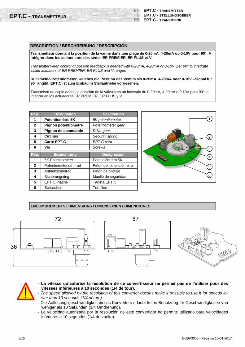
Transmetteur donnant la position de la vanne dans une plage de 0-20mA, 4-20mA ou 0-10V pour 90° .A intégrer dans les actionneurs des séries ER PREMIER, ER PLUS et V. Transmitter when control of position feedback is needed with 0-20mA, 4-20mA or 0-10V per 90° to integrate inside actuators of ER PREMIER, ER PLUS and V ranges. Rückmelde-Potentiometer, welches die Position des Ventils als 0-20mA, 4-20mA oder 0-10V –Signal für 90° angibt. EPT.C ist zum Einbau in Stellantriebe vorgesehen. Transmisor de copio dando la posición de la válvula en un intervalo de 0-20mA, 4-20mA o 0-10V para 90°. a integrar en los actuadores ER PREMIER, ER PLUS y V.
Rep. Désignation Designation
1 Potentiomètre 5K 5K potentiometer
2 Pignon potentiomètre Potentiometer gear
3 Pignon de commande Drive gear
4 Circlips Security spring
5 Carte EPT.C EPT.C card
6 Vis Screws
Rep. Bezeichnung Designación
1 5K Potentiometer Potenciómetro 5K
2 Potentiometerzahnrad Piñón del potenciómetro
3 Antriebszahnrad Piñón de pilotaje
4 Sicherungsring Muelle de seguridad
5 EPT.C Platine Tarjeta EPT.C
6 Schrauben Tornillos
2
3
4
1
5
6
ENCOMBREMENTS / DIMENSIONS / DIMENSIONEN / DIMENCIONES
- La vitesse qu’autorise la résolution de ce convertisseur ne permet pas de l’utiliser pour des vitesses inférieures à 10 secondes (1/4 de tour).
- The speed allowed by the resolution of this converter doesn’t make it possible to use it for speeds lo-wer than 10 seconds (1/4 of turn).
- Die Auflösungsgeschwindigkeit dieses Konverters erlaubt keine Benutzung für Geschwindigkeiten von weniger als 10 Sekunden (1/4 Umdrehung).
- La velocidad autorizada por la resolución de este convertidor no permite utilizarlo para velocidades inferiores a 10 segundos (1/4 de vuelta).
DSBA3300 - Révision 10-01-2017 9/15
EPT.C - TRANSMETTEUR
EPT.C - TRANSMITTER
EPT.C - STELLUNGSGEBER EPT.C - TRANSMISOR
EN D ES
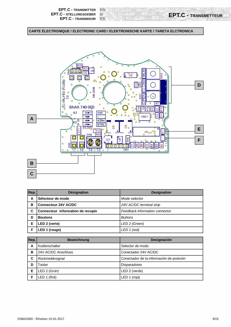
Rep. Désignation Designation
A Sélecteur de mode Mode selector
B Connecteur 24V AC/DC 24V AC/DC terminal strip
C Connecteur information de recopie Feedback information connector
D Boutons Buttons
E LED 2 (verte) LED 2 (Green)
F LED 1 (rouge) LED 1 (red)
F
E
A
B
C
D
CARTE ÉLECTRONIQUE / ELECTRONIC CARD / ELEKTRONISCHE KARTE / TARETA ELCTRONICA
Rep. Bezeichnung Designación
A Kodierschalter Selector de modo
B 24V AC/DC Anschluss Conectador 24V AC/DC
C Rückmeldesignal Conectador de la información de posición
D Taster Disparadores
E LED 2 (Grün) LED 2 (verde)
F LED 1 (Rot) LED 1 (roja)

10/15 DSBA3300 - Révision 10-01-2017
EPT.C - TRANSMETTEUR
EN D
ES
EPT.C - TRANSMITTER
EPT.C - STELLUNGSGEBER EPT.C - TRANSMISOR
DONNÉES TECHNIQUES / TECHNICAL DATAS / TECHNISCHEN DATEN / DATOS TECNICOS
SCHÉMA ÉLECTRIQUE / ELECTRIC WIRING / SCHALTPLAN / ESQUEMA ELÉCTRCIO
ALIMENTATION POWER SUPPLY Betriebsspannung ALIMENTACIÓN
EPT.C Utilisé avec une carte de la gamme PLUS
EPT.C used with a card of PLUS range
EPT.C bei Einbau in PLUS-Serie
EPT.C utilizado con una tajeta de la gama PLUS 12-48 VDC 15-30 VAC
ENTREE INPUT EINGANG ENTRADA Angle de lecture Travel angle Stellwinkel Ángulo de lectura 90° +/-10% 180° +/-10% Ratio de réduction Gear's ratio Untersetzung Ratio de reducción 2.3 1.3
Vitesse de conversion Conversion speed Umwandlungsgeschwindig-keit
Velocidad de conversión 10 Mesures/Seconde
Température Temperature Zul. Umgebungstemperatur Temperatura -10°C / + 60°C
SORTIE COURANT OUTPUT AUSGANG SALIDA EN CORRIENTE 4-20mA / 0-20mA
Résolution Resolution Auflösung Resolución. 20µA Précision de la valeur pleine échelle Full scale accuracy Genauigkeit Precisión del valor +/- 5%
Résistance maximale de charge en mode courant
Maximum load re-sistance Min. Last Resistencia maximal de
cargo en modo "corriente" 800 Ohms
SORTIE TENSION OUTPUT AUSGANG SALIDA EN TENSIÓN 0-10V
Résolution Resolution Auflösung Resolución 10mV
Précision de la valeur pleine échelle Full scale accuracy Genauigkeit Precisión del valor +/- 5%
Résistance minimale de charge en mode tension
Minimum load re-sistance Min. Last
Resistencia maximal de cargo en modo "corriente" 1 K Ohms
DSBA3300 - Révision 10-01-2017 11/15
EPT.C - TRANSMETTEUR
EPT.C - TRANSMITTER
EPT.C - STELLUNGSGEBER EPT.C - TRANSMISOR
EN D ES
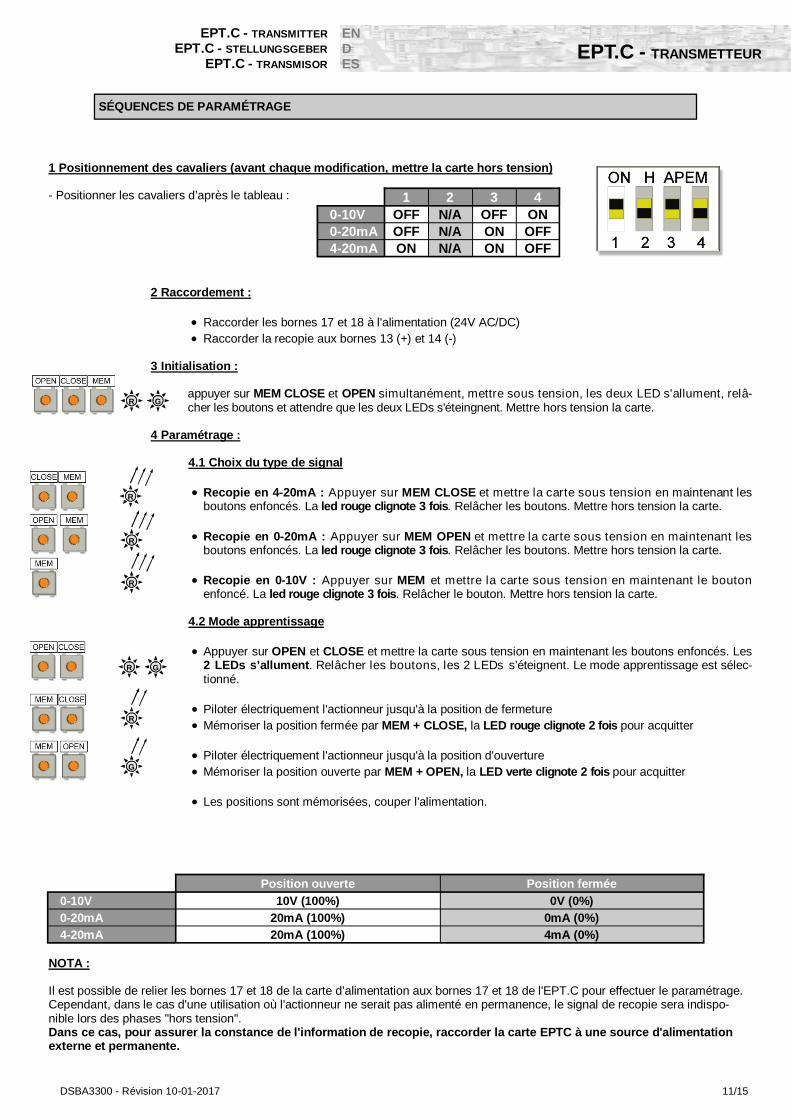
1 2 3 4 0-10V OFF N/A OFF ON 0-20mA OFF N/A ON OFF 4-20mA ON N/A ON OFF
1 Positionnement des cavaliers (avant chaque modification, mettre la carte hors tension) - Positionner les cavaliers d’après le tableau :
2 Raccordement :
Raccorder les bornes 17 et 18 à l'alimentation (24V AC/DC) Raccorder la recopie aux bornes 13 (+) et 14 (-)
3 Initialisation :
appuyer sur MEM CLOSE et OPEN simultanément, mettre sous tension, les deux LED s'allument, relâ-cher les boutons et attendre que les deux LEDs s'éteingnent. Mettre hors tension la carte.
4 Paramétrage : 4.1 Choix du type de signal
Recopie en 4-20mA : Appuyer sur MEM CLOSE et mettre la carte sous tension en maintenant les boutons enfoncés. La led rouge clignote 3 fois. Relâcher les boutons. Mettre hors tension la carte.
Recopie en 0-20mA : Appuyer sur MEM OPEN et mettre la carte sous tension en maintenant les
boutons enfoncés. La led rouge clignote 3 fois. Relâcher les boutons. Mettre hors tension la carte. Recopie en 0-10V : Appuyer sur MEM et mettre la carte sous tension en maintenant le bouton
enfoncé. La led rouge clignote 3 fois. Relâcher le bouton. Mettre hors tension la carte. 4.2 Mode apprentissage
Appuyer sur OPEN et CLOSE et mettre la carte sous tension en maintenant les boutons enfoncés. Les 2 LEDs s’allument. Relâcher les boutons, les 2 LEDs s’éteignent. Le mode apprentissage est sélec-tionné.
Piloter électriquement l'actionneur jusqu'à la position de fermeture Mémoriser la position fermée par MEM + CLOSE, la LED rouge clignote 2 fois pour acquitter
Piloter électriquement l'actionneur jusqu'à la position d'ouverture Mémoriser la position ouverte par MEM + OPEN, la LED verte clignote 2 fois pour acquitter Les positions sont mémorisées, couper l'alimentation.
NOTA : Il est possible de relier les bornes 17 et 18 de la carte d’alimentation aux bornes 17 et 18 de l'EPT.C pour effectuer le paramétrage. Cependant, dans le cas d'une utilisation où l'actionneur ne serait pas alimenté en permanence, le signal de recopie sera indispo-nible lors des phases "hors tension". Dans ce cas, pour assurer la constance de l'information de recopie, raccorder la carte EPTC à une source d'alimentation externe et permanente.
Position ouverte Position fermée
0-10V 10V (100%) 0V (0%) 0-20mA 20mA (100%) 0mA (0%) 4-20mA 20mA (100%) 4mA (0%)
G R
R
R
R
G R
R
G
SÉQUENCES DE PARAMÉTRAGE

12/15 DSBA3300 - Révision 10-01-2017
EPT.C - TRANSMETTEUR
EN D
ES
EPT.C - TRANSMITTER
EPT.C - STELLUNGSGEBER EPT.C - TRANSMISOR
1 2 3 4 0-10V OFF N/A OFF ON 0-20mA OFF N/A ON OFF 4-20mA ON N/A ON OFF
1 Shunts positioning (before each modification, mettre la carte hors tension) - Position the shunts as follows :
2 Connection:
Connect the power supply (24V AC/DC) to the terminals 17 and 18 Connect the feedback signal to the terminals 13 (+) and 14 (-)
3 Initialization:
Press the MEM + CLOSE + OPEN button, and apply the operating voltage to the card, keeping the buttons pressed. The two LEDs lights up. Release the buttons and wait until the LEDs light off. Disconnect the power supply card .
4 Setup : 4.1 Signal type choice:
4-20mA feedback signal: Press the MEM + CLOSE buttons and apply the operating voltage to the card, keeping the buttons pressed. The red LED lights up 3 times. Release the buttons and discon-nect the power supply card .
0-20mA feedback signal: Press MEM + OPEN buttons and apply the operating voltage to the
card, keeping the buttons pressed. The red LED lights up 3 times. Release the buttons and disconnect the power supply card.
0-10V feedback signal: Press MEM button and apply the operating voltage to the card, keeping the
button pressed. The red LED lights up 3 times. Release the button and disconnect the power supply card.
4.2 Learning mode
Press the OPEN + CLOSE buttons and apply the operating voltage to the card, keeping the buttons pressed. The 2 LEDs light up. Release the buttons , the 2 LEDs light off. Le mode The learning mode is selected.
Operate electrically the actuator to its closed position. Save the closed position by pressing MEM + CLOSE, the red LED lights up 2 times to confirm.
Operate electrically the actuator to its open position Save the open position by pressing MEM + OPEN, the green LED lights up 2 times to confirm The positions are saved. disconnect the power supply card.
NOTA : It’s possible to link the terminals 17 and 18 of the power supply card with the terminals 17 and 18 of the EPT.C to execute the pa-rameters selection sequence. However, in the case of a use without permanently power supply, the feedback information won’t be available during “out of power” phases. In this case, to insure the permanence of the feedback information, connect the EPT.C card to an external continuous pow-er supply.
Open position Closed position
0-10V 10V (100%) 0V (0%) 0-20mA 20mA (100%) 0mA (0%) 4-20mA 20mA (100%) 4mA (0%)
G R
R
R
R
G R
R
G
SÉQUENCES DE PARAMÉTRAGE
DSBA3300 - Révision 10-01-2017 13/15
EPT.C - TRANSMETTEUR
EPT.C - TRANSMITTER
EPT.C - STELLUNGSGEBER EPT.C - TRANSMISOR
EN D ES
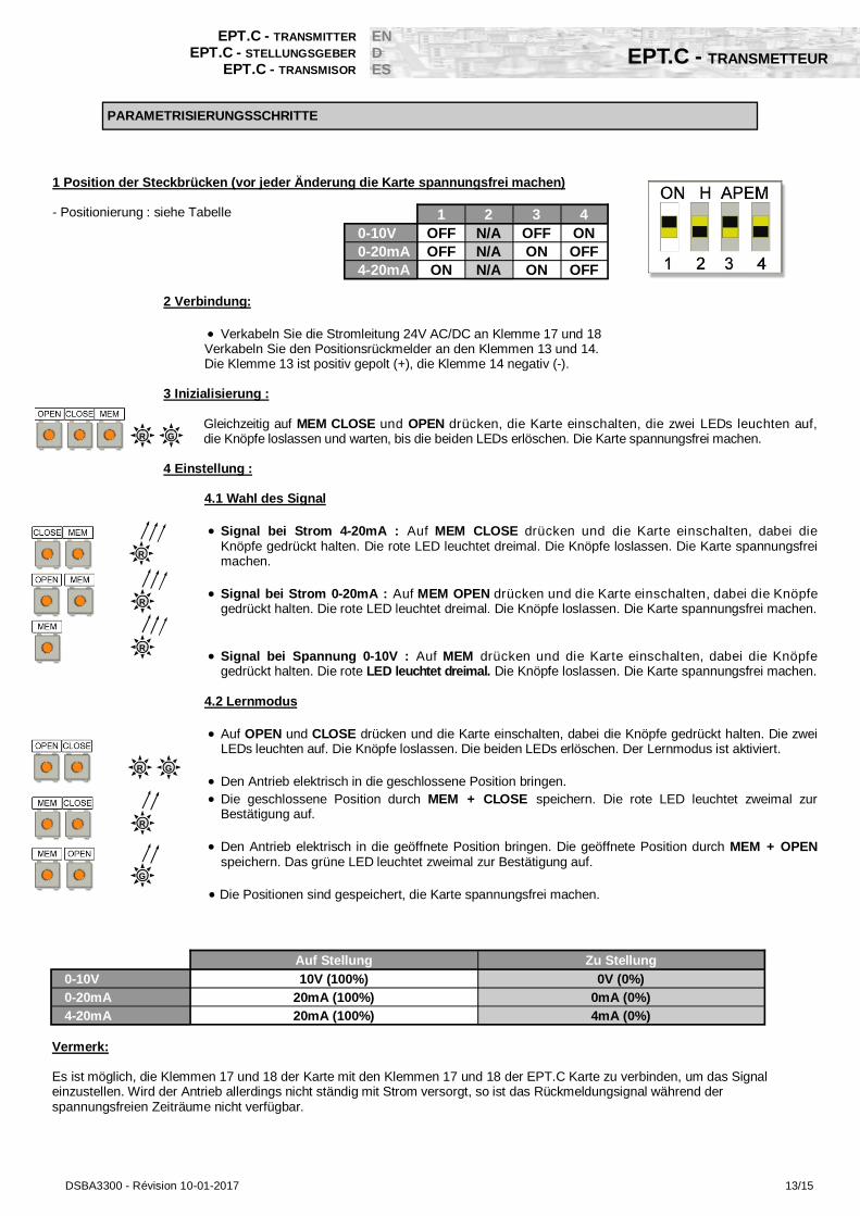
1 2 3 4 0-10V OFF N/A OFF ON 0-20mA OFF N/A ON OFF 4-20mA ON N/A ON OFF
1 Position der Steckbrücken (vor jeder Änderung die Karte spannungsfrei machen) - Positionierung : siehe Tabelle
2 Verbindung:
Verkabeln Sie die Stromleitung 24V AC/DC an Klemme 17 und 18 Verkabeln Sie den Positionsrückmelder an den Klemmen 13 und 14. Die Klemme 13 ist positiv gepolt (+), die Klemme 14 negativ (-). 3 Inizialisierung :
Gleichzeitig auf MEM CLOSE und OPEN drücken, die Karte einschalten, die zwei LEDs leuchten auf, die Knöpfe loslassen und warten, bis die beiden LEDs erlöschen. Die Karte spannungsfrei machen.
4 Einstellung : 4.1 Wahl des Signal
Signal bei Strom 4-20mA : Auf MEM CLOSE drücken und die Karte einschalten, dabei die Knöpfe gedrückt halten. Die rote LED leuchtet dreimal. Die Knöpfe loslassen. Die Karte spannungsfrei machen.
Signal bei Strom 0-20mA : Auf MEM OPEN drücken und die Karte einschalten, dabei die Knöpfe
gedrückt halten. Die rote LED leuchtet dreimal. Die Knöpfe loslassen. Die Karte spannungsfrei machen. Signal bei Spannung 0-10V : Auf MEM drücken und die Karte einschalten, dabei die Knöpfe
gedrückt halten. Die rote LED leuchtet dreimal. Die Knöpfe loslassen. Die Karte spannungsfrei machen. 4.2 Lernmodus
Auf OPEN und CLOSE drücken und die Karte einschalten, dabei die Knöpfe gedrückt halten. Die zwei LEDs leuchten auf. Die Knöpfe loslassen. Die beiden LEDs erlöschen. Der Lernmodus ist aktiviert.
Den Antrieb elektrisch in die geschlossene Position bringen. Die geschlossene Position durch MEM + CLOSE speichern. Die rote LED leuchtet zweimal zur
Bestätigung auf.
Den Antrieb elektrisch in die geöffnete Position bringen. Die geöffnete Position durch MEM + OPEN speichern. Das grüne LED leuchtet zweimal zur Bestätigung auf.
Die Positionen sind gespeichert, die Karte spannungsfrei machen.
Vermerk: Es ist möglich, die Klemmen 17 und 18 der Karte mit den Klemmen 17 und 18 der EPT.C Karte zu verbinden, um das Signal einzustellen. Wird der Antrieb allerdings nicht ständig mit Strom versorgt, so ist das Rückmeldungsignal während der spannungsfreien Zeiträume nicht verfügbar.
Auf Stellung Zu Stellung
0-10V 10V (100%) 0V (0%) 0-20mA 20mA (100%) 0mA (0%) 4-20mA 20mA (100%) 4mA (0%)
G R
R
R
R
G R
R
G
PARAMETRISIERUNGSSCHRITTE
14/15 DSBA3300 - Révision 10-01-2017
EPT.C - TRANSMETTEUR
EN D
ES
EPT.C - TRANSMITTER
EPT.C - STELLUNGSGEBER EPT.C - TRANSMISOR
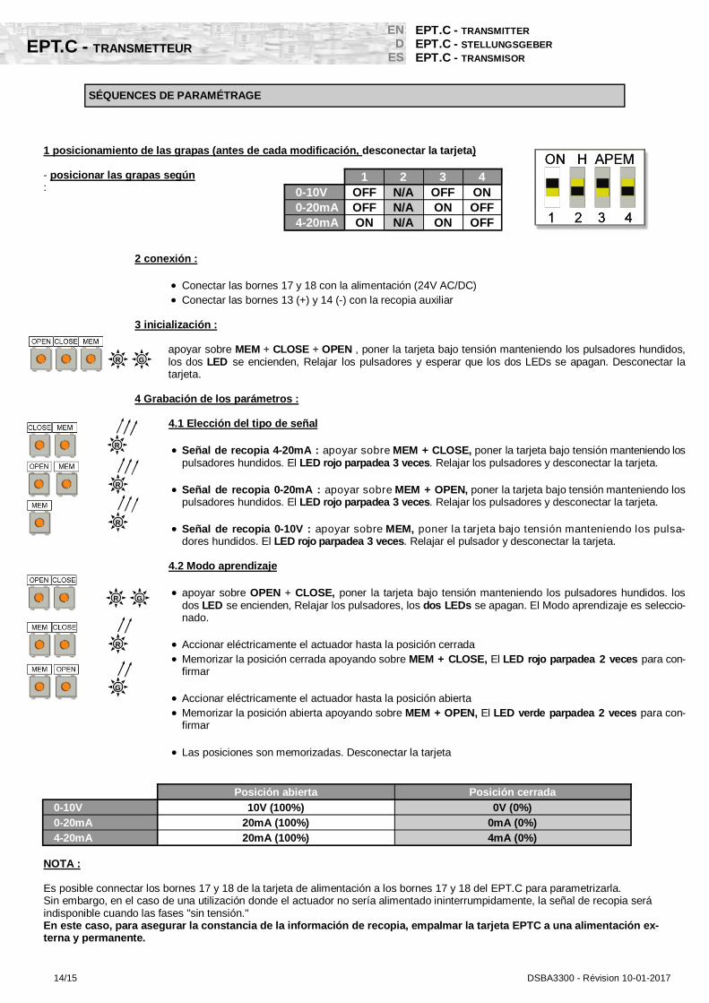
1 2 3 4 0-10V OFF N/A OFF ON 0-20mA OFF N/A ON OFF 4-20mA ON N/A ON OFF
1 posicionamiento de las grapas (antes de cada modificación, desconectar la tarjeta) - posicionar las grapas según :
2 conexión :
Conectar las bornes 17 y 18 con la alimentación (24V AC/DC) Conectar las bornes 13 (+) y 14 (-) con la recopia auxiliar
3 inicialización :
apoyar sobre MEM + CLOSE + OPEN , poner la tarjeta bajo tensión manteniendo los pulsadores hundidos, los dos LED se encienden, Relajar los pulsadores y esperar que los dos LEDs se apagan. Desconectar la tarjeta.
4 Grabación de los parámetros : 4.1 Elección del tipo de señal
Señal de recopia 4-20mA : apoyar sobre MEM + CLOSE, poner la tarjeta bajo tensión manteniendo los pulsadores hundidos. El LED rojo parpadea 3 veces. Relajar los pulsadores y desconectar la tarjeta.
Señal de recopia 0-20mA : apoyar sobre MEM + OPEN, poner la tarjeta bajo tensión manteniendo los
pulsadores hundidos. El LED rojo parpadea 3 veces. Relajar los pulsadores y desconectar la tarjeta. Señal de recopia 0-10V : apoyar sobre MEM, poner la tarjeta bajo tensión manteniendo los pulsa-
dores hundidos. El LED rojo parpadea 3 veces. Relajar el pulsador y desconectar la tarjeta. 4.2 Modo aprendizaje
apoyar sobre OPEN + CLOSE, poner la tarjeta bajo tensión manteniendo los pulsadores hundidos. los dos LED se encienden, Relajar los pulsadores, los dos LEDs se apagan. El Modo aprendizaje es seleccio-nado.
Accionar eléctricamente el actuador hasta la posición cerrada Memorizar la posición cerrada apoyando sobre MEM + CLOSE, El LED rojo parpadea 2 veces para con-
firmar
Accionar eléctricamente el actuador hasta la posición abierta Memorizar la posición abierta apoyando sobre MEM + OPEN, El LED verde parpadea 2 veces para con-
firmar Las posiciones son memorizadas. Desconectar la tarjeta
NOTA : Es posible connectar los bornes 17 y 18 de la tarjeta de alimentación a los bornes 17 y 18 del EPT.C para parametrizarla. Sin embargo, en el caso de una utilización donde el actuador no sería alimentado ininterrumpidamente, la señal de recopia será indisponible cuando las fases "sin tensión." En este caso, para asegurar la constancia de la información de recopia, empalmar la tarjeta EPTC a una alimentación ex-terna y permanente.
Posición abierta Posición cerrada
0-10V 10V (100%) 0V (0%) 0-20mA 20mA (100%) 0mA (0%) 4-20mA 20mA (100%) 4mA (0%)
G R
R
R
R
G R
R
G
SÉQUENCES DE PARAMÉTRAGE

DSBA3300 - Révision 10-01-2017 15/15
DESCRIPTION / BESCHREIBUNG / DESCRIPCIÓN
Carte 2 contacts fins de course permettant une information de recopie supplémentaire 2 limit switches card allowing an extra feedback information 2 Endschalter Karte für zusätzliche Rückmeldung Tarjeta con 2 contactos dando la posibilidad de una información de recopia suplementaria
Rep. Désignation Designation
1 Circuit imprimé Circuit board
2 Contacts fin de course End limit switches
3 Borniers Terminal strips
4 Support plastique Plastic bracket
5 Cames et circlips Cams and circlips
6 Vis M2,2x6,5 M2,2x6,5 screws
Rep. Bezeichnung Designación
1 Leiterplatte Circuito impreso
2 Endschalterkontakte Contactos de final de carrera
3 Verbindung Terminal de conexión
4 Kunststoff Halterung Soporte de plástico
5 Nocken und Sicherungsbügel Levas y muele de seguridad
6 M2,2x6,5 Schrauben Tornillos M2,2x6,5
2
4 5 6
1
3
3
REP DESIGNATION
BESCHREIBUNG / DESIGNACIÓN
FC3 Fin de course auxiliaire 3 Auxiliary limit switch 3 Zusätzlicher Endschalter 3 Final de carrera auxiliar 3
FC4 Fin de course auxiliaire 4 Auxiliary limit switch 4 Zusätzlicher Endschalter 4 Final de carrera auxiliar 4
R Recopie client Feedback information Rückmeldung Recopia
24
25
26
27
28
29
FC3
FC4
FC4(NO)
COM
FC3(NO)
COM
R
SCHÉMA ÉLECTRIQUE / ELECTRIC WIRING / SCHALTPLAN / ESQUEMA ELÉCTRCIO
- Le bornier "client" doit être câblé avec des câbles rigides. Si la tension appliquée est supérieure à 42V, l'utilisateur doit prévoir un fusible dans la ligne d'alimentation.
- The "customer" terminal must be connected with rigid wires. If the applied voltage is higher than 42V, the user must foresee a fuse in the power supply line.
- Die Klemmen “Kunde” müssen mit biegesteif Anschlusskabel verkabelt werden. Sollte die Spannung 42v übersch-ritten, so muss vom Anwender eine Sicherung in der Stromzufuhr vorgesehen werden.
- Los finales de carrera deben ser conectados con cables rígidos. Si la tensión aplicada es superiora a 42V, el usua-rio debe prever un fusible en la alimentación.
- Pour une utilisation avec de grandes longueurs de câbles, le courant induit généré par les câbles ne doit pas dépasser 1mA - For a use with a long power supply wiring, the induction current generated by the wires musn't be higher than 1mA - Bei Verwendung einer langen Zuleitung für die Spannungsversorgung darf die Induktionsspannung der Leitung nicht
größer als 1mA sein. -
Tension maximale / Maximal voltage / Max. Spannung / Volatje máximo 240V AC/DC max.
Courant maximal / Maximal current / Max. Ström / Corriente máxima
DONNÉES TECHNIQUES / TECHNICAL DATAS / TECHNISCHEN / DATOS TECNICOS
EFC.2 - CARTE 2 CONTACTS SUPPLÉMENTAIRES
EFC.2 - 2 EXTRA LIMIT SWITCHES CARD
EFC.2 - 2 ZUSÄTZLICHE ENDSCHALTER KARTE EFC.2 - TARJETA CON 2 CONTACTOS SUPLEMENTARIOS
EN D ES