Embed Size (px)
Citation preview
GB/2017.03 – Ident-No. 228493
1
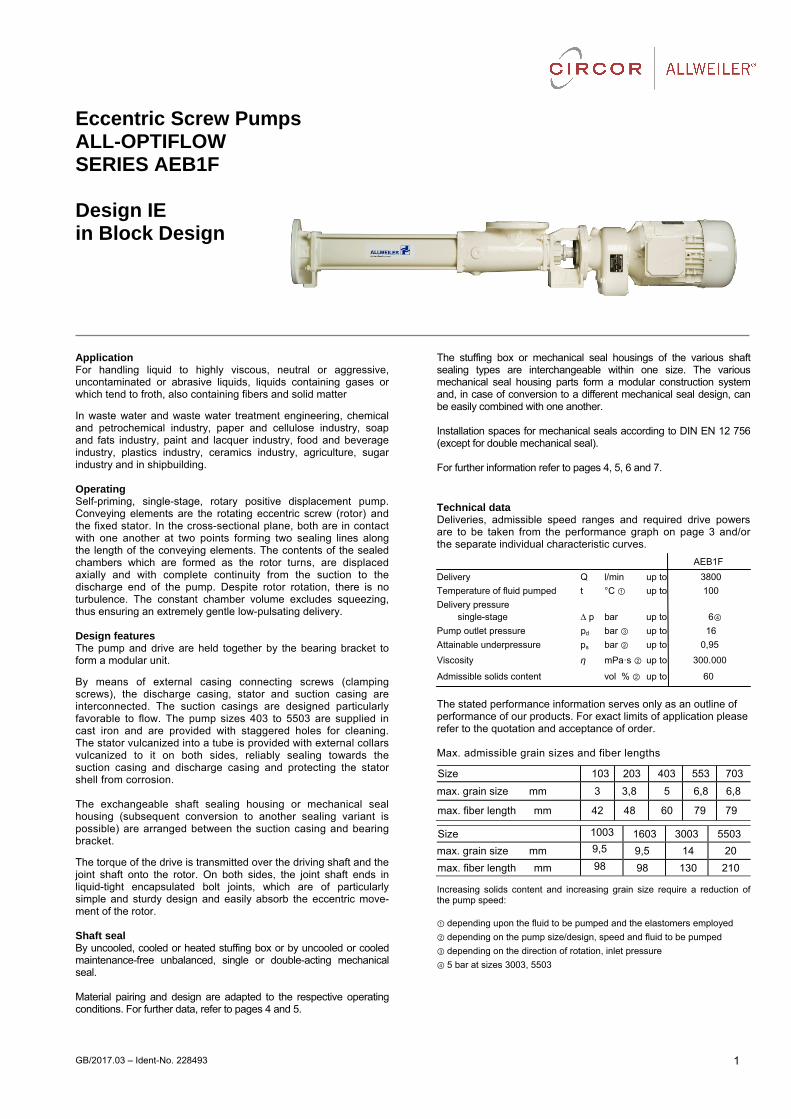
Eccentric Screw Pumps ALL-OPTIFLOW SERIES AEB1F Design IE in Block Design Application For handling liquid to highly viscous, neutral or aggressive, uncontaminated or abrasive liquids, liquids containing gases or which tend to froth, also containing fibers and solid matter
In waste water and waste water treatment engineering, chemical and petrochemical industry, paper and cellulose industry, soap and fats industry, paint and lacquer industry, food and beverage industry, plastics industry, ceramics industry, agriculture, sugar industry and in shipbuilding. Operating Self-priming, single-stage, rotary positive displacement pump. Conveying elements are the rotating eccentric screw (rotor) and the fixed stator. In the cross-sectional plane, both are in contact with one another at two points forming two sealing lines along the length of the conveying elements. The contents of the sealed chambers which are formed as the rotor turns, are displaced axially and with complete continuity from the suction to the discharge end of the pump. Despite rotor rotation, there is no turbulence. The constant chamber volume excludes squeezing, thus ensuring an extremely gentle low-pulsating delivery. Design features The pump and drive are held together by the bearing bracket to form a modular unit.
By means of external casing connecting screws (clamping screws), the discharge casing, stator and suction casing are interconnected. The suction casings are designed particularly favorable to flow. The pump sizes 403 to 5503 are supplied in cast iron and are provided with staggered holes for cleaning. The stator vulcanized into a tube is provided with external collars vulcanized to it on both sides, reliably sealing towards the suction casing and discharge casing and protecting the stator shell from corrosion. The exchangeable shaft sealing housing or mechanical seal housing (subsequent conversion to another sealing variant is possible) are arranged between the suction casing and bearing bracket.
The torque of the drive is transmitted over the driving shaft and the joint shaft onto the rotor. On both sides, the joint shaft ends in liquid-tight encapsulated bolt joints, which are of particularly simple and sturdy design and easily absorb the eccentric move-ment of the rotor. Shaft seal By uncooled, cooled or heated stuffing box or by uncooled or cooled maintenance-free unbalanced, single or double-acting mechanical seal. Material pairing and design are adapted to the respective operating conditions. For further data, refer to pages 4 and 5.
The stuffing box or mechanical seal housings of the various shaft sealing types are interchangeable within one size. The various mechanical seal housing parts form a modular construction system and, in case of conversion to a different mechanical seal design, can be easily combined with one another. Installation spaces for mechanical seals according to DIN EN 12 756 (except for double mechanical seal). For further information refer to pages 4, 5, 6 and 7.
Technical data Deliveries, admissible speed ranges and required drive powers are to be taken from the performance graph on page 3 and/or the separate individual characteristic curves.
AEB1F
Delivery Q l/min up to 3800
Temperature of fluid pumped t °C ① up to 100
Delivery pressure single-stage ∆ p bar up to 6④
Pump outlet pressure pd bar ③ up to 16
Attainable underpressure ps bar ② up to 0,95
Viscosity η mPa·s ② up to 300.000
Admissible solids content vol % ② up to 60
The stated performance information serves only as an outline of performance of our products. For exact limits of application please refer to the quotation and acceptance of order.
Max. admissible grain sizes and fiber lengths
Size 103 203 403 553 703
max. grain size mm 3 3,8 5 6,8 6,8
max. fiber length mm 42 48 60 79 79
Size 1003 1603 3003 5503
max. grain size mm 9,5 9,5 14 20
max. fiber length mm 98 98 130 210
Increasing solids content and increasing grain size require a reduction of the pump speed: ① depending upon the fluid to be pumped and the elastomers employed
② depending on the pump size/design, speed and fluid to be pumped
③ depending on the direction of rotation, inlet pressure ④ 5 bar at sizes 3003, 5503
2
GB/2017.03 – Ident-No. 228493
Bearings The driving and the joint shaft are situated in the reinforced bearings of the electric motors, gear motors or control gear which also absorb the generated axial forces. As all drives are only supplied with reinforced bearings it must be assured that the assigned pumps can be run at full capacity within their permissible application limits. Drive The drive can be provided by non-explosion-proof or explosion-proof three-phase motors, gear motors or control gear. For drive options see page 10. For technical data and dimensions, please refer to the separate sales documentation, data sheet 19-00-0000-111-3. A considerable advantage is the fact that within a pump size the connection dimensions for all drive types are the same. This allows a later change to a different drive type or size. Installation AEB pumps may be installed horizontally or vertically, depending on the shaft seal. In case of vertical arrangement, “shaft shank downwards” is not admissible. Exchangeability of components The components of all eccentric screw pumps are of a modular design. This allows a simple and cost-effective spare parts management even if different series and designs of pumps are used.

GB/2017.03 – Ident-No. 228493
3
Performance graph For a rough selection of the pump size and speed as a function of the requested delivery and kind of fluid to be pumped. Vg”m” = available, mean sliding speed of the rotor in the stator.
Sizes of the series AEB1F Data on the performance range not covered by AEB1F series are to be taken from the last page of this brochure and/or the individual brochures of the other series. For exact performance data, please refer to the individual characteristics.
4
GB/2017.03 – Ident-No. 228493
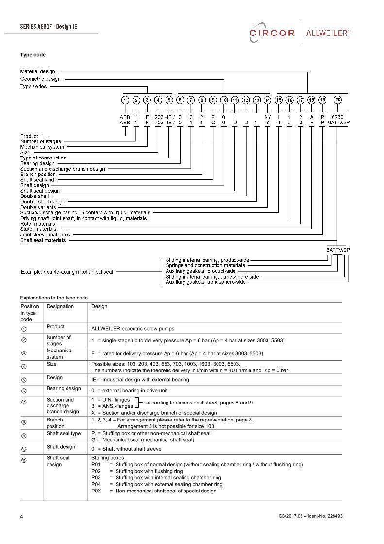
Type code
Explanations to the type code
Position in type code
Designation Design
① Product ALLWEILER eccentric screw pumps
② Number of stages
1 = single-stage up to delivery pressure ∆p = 6 bar (∆p = 4 bar at sizes 3003, 5503)
③ Mechanical system
F = rated for delivery pressure ∆p = 6 bar (∆p = 4 bar at sizes 3003, 5503)
④ Size Possible sizes: 103, 203, 403, 553, 703, 1003, 1603, 3003, 5503. The numbers indicate the theoretic delivery in l/min with n = 400 1/min and ∆p = 0 bar
⑤ Design IE = Industrial design with external bearing
⑥ Bearing design 0 = external bearing in drive unit
⑦ Suction and discharge branch design
1 = DIN-flanges 3 = ANSI-flanges X = Suction and/or discharge branch of special design
⑧ Branch position
1, 2, 3, 4 – For arrangement please refer to the representation, page 8. Arrangement 3 is not possible for size 103.
⑨ Shaft seal type P = Stuffing box or other non-mechanical shaft seal G = Mechanical seal (mechanical shaft seal)
⑩ Shaft design 0 = Shaft without shaft sleeve
⑪ Shaft seal design
Stuffing boxes P01 = Stuffing box of normal design (without sealing chamber ring / without flushing ring) P02 = Stuffing box with flushing ring P03 = Stuffing box with internal sealing chamber ring P04 = Stuffing box with external sealing chamber ring P0X = Non-mechanical shaft seal of special design
according to dimensional sheet, pages 8 and 9
GB/2017.03 – Ident-No. 228493
5
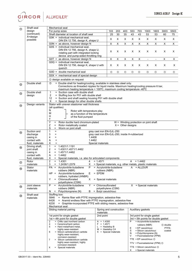
⑪ Shaft seal design (continued) X=design possible
Mechanical seal For pump sizes 103 203 403 553 703 1003 1603 3003 5503 Shaft diameter at location of shaft seal 25 30 35 43 43 53 53 60 75 G0K = individual mechanical seal, DIN EN 12 756, design K, shape U X X X X X X X X X
G0N = as above, however design N X X X X X X X X X G0S = individual mechanical seal, DIN EN 12 756, design K, shape U, rotating part with integrated locking device and pump-sided throttling ring
X X X X X X X X X
G0T = as above, however design N X X X X X - - X X G0Q = individual mechanical seal, DIN EN 12 756, design K, shape U with quench
X X X X X X X X X
G0D = double mechanical seal ① ① ① ① ① ① ① ① ①
G0X = mechanical seal of special design
① design available on request
⑫ Double shell
D = Double shell for heating/cooling, available in stainless steel only. Connections as threaded nipples for liquid media. Maximum heating/cooling pressure 6 bar, maximum heating temperature + 100ºC, maximum cooling temperature -40ºC
⑬ Double shell design
1 = Suction case with double shell 2 = Stuffing box for P01 with double shell 12 = Suction and shaft sealing housing P01 with double shell X = Special design for other double shells
⑭ Design variants Stator with uneven elastomer wall thickness (all qualities) N M H T Y = Rotor ductile hard chromium-plated W = Winding protection on joint shaft Z = Rotor metallically coated X = Other designs S = Worm on joint shaft
⑮ Suction and discharge casing in contact with fluid, materials
1 = gray cast iron EN-GJL-250 3 = gray cast iron EN-GJL-250, inside H-rubberized 4 = 1.4408 A = 1.4462 X = Special materials
⑯ Driving shaft, joint shaft casing in contact with fluid, materials
1 = 1.4021/1.1191 2 = 1.4301/1.4571/1.4462 4 = 1.4571/1.4462 A = 1.4462 X = Special materials, i.e. also for articulated components
⑰ Rotor materials
2 = 1.4301 4 = 1.4571 A = 1.4462 3 = 1.2436/1.2379 X = Special materials, e.g. other metals, plastic materials
⑱ Stator materials
PA = Acrylonitrile-butadiene P = Acrylonitrile-butadiene A = ALLDUR rubbers (NBR) rubbers (NBR) HP = Acrylonitrile-butadiene E = EPDM rubbers, hydrated (HNBR) Y = Chlorosulfonated X = Special materials polyethylene (CSM)
⑲ Joint sleeve materials
P = Acrylonitrile-butadiene Y = Chlorosulfonated X = Special materials rubbers (NBR) polyethylene (CSM) N = Polychloroprene (N) B = Butyl caoutchouc
⑳ Shaft seal materials
Stuffing box: 5846 = Ramie fiber with PTFE impregnation, asbestos-free 6426 = Aramid endless fiber with PTFE impregnation, asbestos-free 6230 = Graphite-incorporated PTFE with sliding means, asbestos-free Mechanical seal: Sliding material pairing Spring and construction
materials Auxilliary gaskets
1st point for single gasket 1st + 4th point for double gasket
2nd point 3rd point for single gasket 3rd + 5th points for double gasket
2 = CrMo cast iron/hard carbon 4 = Ceramics/hard carbon 5 = Hard metal/hard metal,
highly wear-resistant 6 = Silicon carbide/silicon carbide highly wear-resistant, corrosion-resistant 7 = Silicon carbide/silicon carbide highly wear-resistant, highly corrosion-resistant X = Special materials
A = 1.4300 F = 1.4571 L = Hastelloy B M = Hastelloy C4 X = Special materials
P = Acrylonitrile-butadiene
rubbers (NBR) ① double
E = EP caoutchouc PTFE- S = Silicon caoutchouc coated N = Polychloroprene (N) V = Fluoroelastomer (FPM)
TTE = EP caoutchouc ①
TTV = Fluoroelastomer (FPM) ①
TTS = Silicon caoutchouc ①
X = Special materials
Rotor with temperature play as a function of the temperature of the fluid pumped
6
GB/2017.03 – Ident-No. 228493
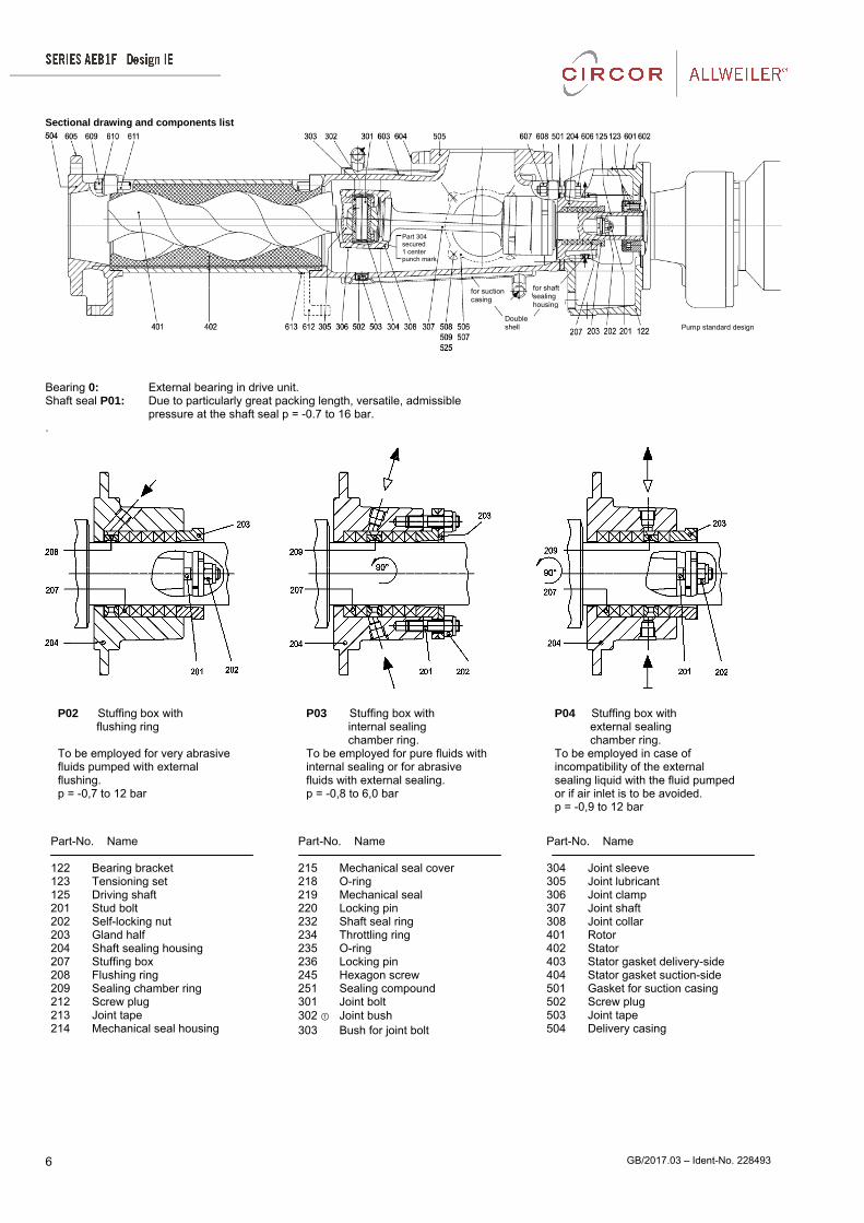
Sectional drawing and components list
Bearing 0: External bearing in drive unit. Shaft seal P01: Due to particularly great packing length, versatile, admissible pressure at the shaft seal p = -0.7 to 16 bar. .
Part-No. Name 122 Bearing bracket 123 Tensioning set 125 Driving shaft 201 Stud bolt 202 Self-locking nut 203 Gland half 204 Shaft sealing housing 207 Stuffing box 208 Flushing ring 209 Sealing chamber ring 212 Screw plug 213 Joint tape 214 Mechanical seal housing
Part-No. Name 215 Mechanical seal cover 218 O-ring 219 Mechanical seal 220 Locking pin 232 Shaft seal ring 234 Throttling ring 235 O-ring 236 Locking pin 245 Hexagon screw 251 Sealing compound 301 Joint bolt 302 ① Joint bush 303 Bush for joint bolt
Part-No. Name 304 Joint sleeve 305 Joint lubricant 306 Joint clamp 307 Joint shaft 308 Joint collar 401 Rotor 402 Stator 403 Stator gasket delivery-side 404 Stator gasket suction-side 501 Gasket for suction casing 502 Screw plug 503 Joint tape 504 Delivery casing
P02 Stuffing box with flushing ring To be employed for very abrasive fluids pumped with external flushing. p = -0,7 to 12 bar
P03 Stuffing box with internal sealing chamber ring. To be employed for pure fluids with internal sealing or for abrasive fluids with external sealing. p = -0,8 to 6,0 bar
P04 Stuffing box with external sealing chamber ring. To be employed in case of incompatibility of the external sealing liquid with the fluid pumped or if air inlet is to be avoided. p = -0,9 to 12 bar
Double shell
for shaft sealing housing
for suction casing
Part 304 secured 1 center punch mark
Pump standard design
GB/2017.03 – Ident-No. 228493
7
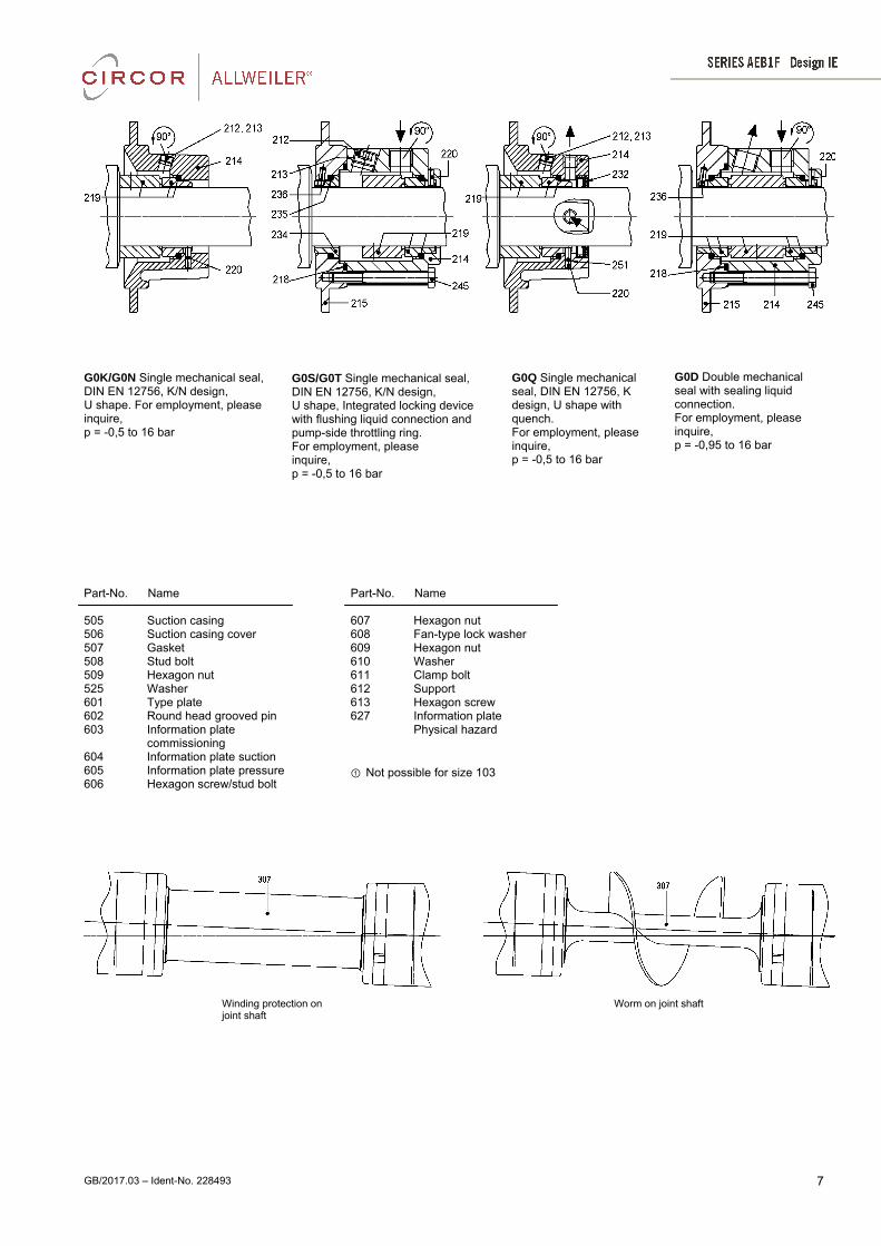
G0K/G0N Single mechanical seal, DIN EN 12756, K/N design, U shape. For employment, please inquire, p = -0,5 to 16 bar
G0S/G0T Single mechanical seal, DIN EN 12756, K/N design, U shape, Integrated locking device with flushing liquid connection and pump-side throttling ring. For employment, please inquire, p = -0,5 to 16 bar
G0Q Single mechanical seal, DIN EN 12756, K design, U shape with quench. For employment, please inquire, p = -0,5 to 16 bar
G0D Double mechanical seal with sealing liquid connection. For employment, please inquire, p = -0,95 to 16 bar
Part-No. Name 505 Suction casing 506 Suction casing cover 507 Gasket 508 Stud bolt 509 Hexagon nut 525 Washer 601 Type plate 602 Round head grooved pin 603 Information plate commissioning 604 Information plate suction 605 Information plate pressure 606 Hexagon screw/stud bolt
Part-No. Name 607 Hexagon nut 608 Fan-type lock washer 609 Hexagon nut 610 Washer 611 Clamp bolt 612 Support 613 Hexagon screw 627 Information plate
Physical hazard ① Not possible for size 103
Winding protection on joint shaft
Worm on joint shaft
8
GB/2017.03 – Ident-No. 228493
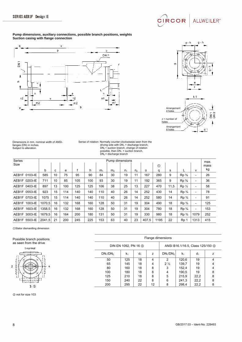
Pump dimensions, auxiliary connections, possible branch positions, weights Suction casing with flange connection
Series Size
Pump dimensions max. mass
kg b c e f h m1 m2 n1 n2 o
①
q s L v
AEB1F 0103-IE 585 10 75 95 90 84 30 19 11 167 280 9 Rp ⅜ - 26
AEB1F 0203-IE 711 10 85 105 100 93 30 19 11 192 365 9 Rp ⅜ - 36
AEB1F 0403-IE 897 13 100 125 125 106 38 25 13 227 470 11,5 Rp ½ - 58
AEB1F 0553-IE 923 15 114 140 140 110 40 26 14 252 430 14 Rp ¾ - 78
AEB1F 0703-IE 1075 15 114 140 140 110 40 26 14 252 580 14 Rp ¾ - 91
AEB1F 1003-IE 1070,5 16 132 168 160 128 50 31 19 304 490 18 Rp ¾ - 125
AEB1F 1603-IE 1358,5 16 132 168 160 128 50 31 19 304 780 18 Rp ¾ - 153
AEB1F 3003-IE 1679,5 16 164 200 180 131 50 31 19 330 980 18 Rp ¾ 1079 252
AEB1F 5503-IE 2041,5 21 200 245 225 153 63 40 23 407,5 1195 22 Rp 1 1313 415
①Stator dismantling dimension
Possible branch positions as seen from the drive ② not for size 103
Flange dimensions
DIN EN 1092, PN 16 ⑤ ANSI B16.1/16.5, Class 125/150 ④
DN1/DN2 k1 d1 z DN1/DN2 k1 d1 z
50 65 80 100 125 150 200
125 145 160 180 210 240 295
18 18 18 18 18 22 22
4 4 8 8 8 8
12
2 2 ½
3 4 5 6 8
120,6 139,7 152,4 190,5 215,9 241,3 298,4
19 19 19 19
22,2 22,2 22,2
4 4 4 8 8 8 8
Dimensions in mm, nominal width of ANSI-llanges (DN) in inches. Subject to alteration.
Sense of rotation: Normally counter-clockwiseas seen from thedriving side with DN1 = discharge branch, DN2 = suction branch, change of rotation possible, then DN1 = suction branch, DN2 = discharge branch
Arrangement 4 holes_____
Arrangement 8 holes_____
z = number of holes __________
GB/2017.03 – Ident-No. 228493
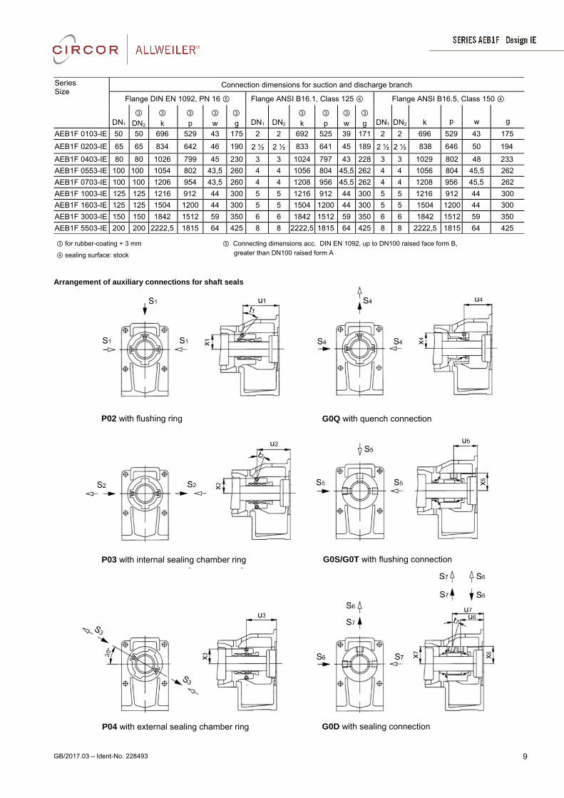
9
Series Size
Connection dimensions for suction and discharge branch
Flange DIN EN 1092, PN 16 ⑤ Flange ANSI B16.1, Class 125 ④ Flange ANSI B16.5, Class 150 ④
DN1
③
DN2
③
k
③
p
③
w
③
g
DN1
DN2
③
k
③
p
③
w
③
g
DN1
DN2
k
p
w
g
AEB1F 0103-IE 50 50 696 529 43 175 2 2 692 525 39 171 2 2 696 529 43 175
AEB1F 0203-IE 65 65 834 642 46 190 2 ½ 2 ½ 833 641 45 189 2 ½ 2 ½ 838 646 50 194
AEB1F 0403-IE 80 80 1026 799 45 230 3 3 1024 797 43 228 3 3 1029 802 48 233
AEB1F 0553-IE 100 100 1054 802 43,5 260 4 4 1056 804 45,5 262 4 4 1056 804 45,5 262
AEB1F 0703-IE 100 100 1206 954 43,5 260 4 4 1208 956 45,5 262 4 4 1208 956 45,5 262
AEB1F 1003-IE 125 125 1216 912 44 300 5 5 1216 912 44 300 5 5 1216 912 44 300
AEB1F 1603-IE 125 125 1504 1200 44 300 5 5 1504 1200 44 300 5 5 1504 1200 44 300
AEB1F 3003-IE 150 150 1842 1512 59 350 6 6 1842 1512 59 350 6 6 1842 1512 59 350
AEB1F 5503-IE 200 200 2222,5 1815 64 425 8 8 2222,5 1815 64 425 8 8 2222,5 1815 64 425
Arrangement of auxiliary connections for shaft seals
⑤ Connecting dimensions acc. DIN EN 1092, up to DN100 raised face form B,
greater than DN100 raised form A ③ for rubber-coating + 3 mm ④ sealing surface: stock
P02 with flushing ring G0Q with quench connection
G0S/G0T with flushing connection
P04 with external sealing chamber ring G0D with sealing connection
P04 with external sealing chamber ring G0D with sealing connection G0D with sealing connection G0D with sealing connection
G0S/G0T with flushing connection P03 with internal sealing chamber ring P03 with internal sealing chamber ring
10
GB/2017.03 – Ident-No. 228493
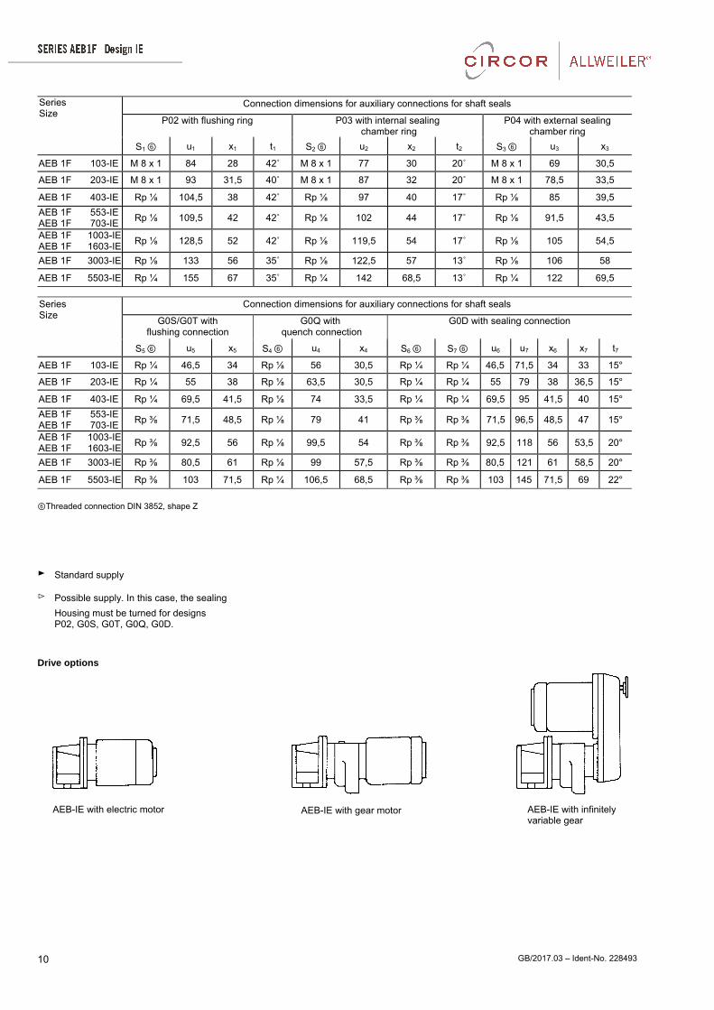
Series Size
Connection dimensions for auxiliary connections for shaft seals
P02 with flushing ring P03 with internal sealing chamber ring
P04 with external sealing chamber ring
S1 ⑥ u1 x1 t1 S2 ⑥ u2 x2 t2 S3 ⑥ u3 x3
AEB 1F 103-IE M 8 x 1 84 28 42˚ M 8 x 1 77 30 20˚ M 8 x 1 69 30,5
AEB 1F 203-IE M 8 x 1 93 31,5 40˚ M 8 x 1 87 32 20˚ M 8 x 1 78,5 33,5
AEB 1F 403-IE Rp ⅛ 104,5 38 42˚ Rp ⅛ 97 40 17˚ Rp ⅛ 85 39,5
AEB 1F 553-IE AEB 1F 703-IE
Rp ⅛ 109,5 42 42˚ Rp ⅛ 102 44 17˚ Rp ⅛ 91,5 43,5
AEB 1F 1003-IE AEB 1F 1603-IE
Rp ⅛ 128,5 52 42˚ Rp ⅛ 119,5 54 17˚ Rp ⅛ 105 54,5
AEB 1F 3003-IE Rp ⅛ 133 56 35˚ Rp ⅛ 122,5 57 13˚ Rp ⅛ 106 58
AEB 1F 5503-IE Rp ¼ 155 67 35˚ Rp ¼ 142 68,5 13˚ Rp ¼ 122 69,5
Series Size
Connection dimensions for auxiliary connections for shaft seals
G0S/G0T with flushing connection
G0Q with quench connection
G0D with sealing connection
S5 ⑥ u5 x5 S4 ⑥ u4 x4 S6 ⑥ S7 ⑥ u6 u7 x6 x7 t7
AEB 1F 103-IE Rp ¼ 46,5 34 Rp ⅛ 56 30,5 Rp ¼ Rp ¼ 46,5 71,5 34 33 15°
AEB 1F 203-IE Rp ¼ 55 38 Rp ⅛ 63,5 30,5 Rp ¼ Rp ¼ 55 79 38 36,5 15°
AEB 1F 403-IE Rp ¼ 69,5 41,5 Rp ⅛ 74 33,5 Rp ¼ Rp ¼ 69,5 95 41,5 40 15°
AEB 1F 553-IE AEB 1F 703-IE
Rp ⅜ 71,5 48,5 Rp ⅛ 79 41 Rp ⅜ Rp ⅜ 71,5 96,5 48,5 47 15°
AEB 1F 1003-IE AEB 1F 1603-IE
Rp ⅜ 92,5 56 Rp ⅛ 99,5 54 Rp ⅜ Rp ⅜ 92,5 118 56 53,5 20°
AEB 1F 3003-IE Rp ⅜ 80,5 61 Rp ⅛ 99 57,5 Rp ⅜ Rp ⅜ 80,5 121 61 58,5 20°
AEB 1F 5503-IE Rp ⅜ 103 71,5 Rp ¼ 106,5 68,5 Rp ⅜ Rp ⅜ 103 145 71,5 69 22°
⑥Threaded connection DIN 3852, shape Z
► Standard supply
▻ Possible supply. In this case, the sealing
Housing must be turned for designs P02, G0S, G0T, G0Q, G0D.
Drive options
AEB-IE with electric motor AEB-IE with gear motor AEB-IE with infinitely variable gear

GB/2017.03 – Ident-No. 228493
11
Subject to technical alterations.
ALLWEILER GmbH Postfach 200123 • 46223 Bottrop Kirchhellener Ring 77–79 • 46244 Bottrop Germany Tel. +49 (0)2045 966-60 Fax +49 (0)2045 966-679 E-mail: [email protected] Internet: http://www.allweiler.com
GB/2017.03 – Ident-No. 228493
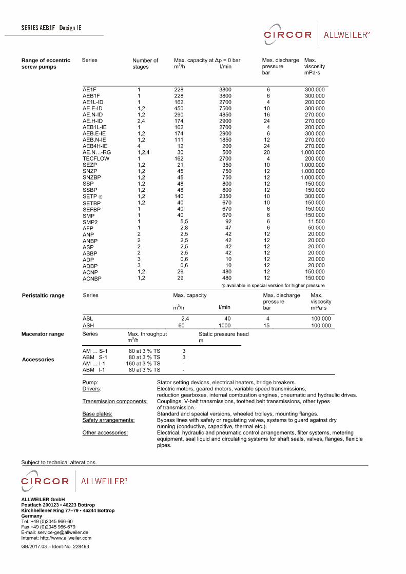
AE1F AEB1F AE1L-ID AE.E-ID AE.N-ID AE.H-ID AEB1L-IE AEB.E-IE AEB.N-IE AEB4H-IE AE.N…-RG TECFLOW SEZP SNZP SNZBP SSP SSBP SETP ① SETBP SEFBP SMP SMP2 AFP ANP ANBP ASP ASBP ADP ADBP ACNP ACNBP
1 1 1 1,2 1,2 2,4 1 1,2 1,2 4 1,2,4 1 1,2 1,2 1,2 1,2 1,2 1,2 1,2 1 1 1 1 2 2 2 2 3 3 1,2 1,2
228 228 162 450 290 174 162 174 111 12 30 162 21 45 45 48 48 140 40 40 40 5,5 2,8 2,5 2,5 2,5 2,5 0,6 0,6 29 29
3800 3800 2700 7500 4850 2900 2700 2900 1850
200 500
2700 350 750 750 800 800
2350 670 670 670
92 47 42 42 42 42 10 10
480 480
6 6 4
10 16 24
4 6
12 24 20
4 10 12 12 12 12 10 10
6 6 6 6
12 12 12 12 12 12 12 12
300.000 300.000 200.000 300.000 270.000 270.000 200.000 300.000 270.000 270.000
1.000.000 200.000
1.000.000 1.000.000 1.000.000
150.000 150.000 300.000 150.000 150.000 150.000
11.500 50.000 20.000 20.000 20.000 20.000 20.000 20.000
150.000 150.000
① available in special version for higher pressure
ASL ASH
2,4 60
40 1000
4 15
100.000 100.000
AM … S-1 80 at 3 % TS 3 ABM S-1 80 at 3 % TS 3 AM … l-1 160 at 3 % TS - ABM l-1 80 at 3 % TS -
Pump: Stator setting devices, electrical heaters, bridge breakers. Drivers: Electric motors, geared motors, variable speed transmissions, reduction gearboxes, internal combustion engines, pneumatic and hydraulic drives. Transmission components: Couplings, V-belt transmissions, toothed belt transmissions, other types of transmission. Base plates: Standard and special versions, wheeled trolleys, mounting flanges. Safety arrangements: Bypass lines with safety or regulating valves, systems to guard against dry running (conductive, capacitive, thermal etc.). Other accessories: Electrical, hydraulic and pneumatic control arrangements, filter systems, metering
equipment, seal liquid and circulating systems for shaft seals, valves, flanges, flexible pipes.
Peristaltic range Series Max. capacity m3/h l/min
Max. discharge pressure bar
Max. viscosity mPa·s
Macerator range Series Max. throughput m3/h
Static pressure head m
Accessories
Range of eccentric screw pumps
Series Number of stages
Max. capacity at ∆p = 0 bar m3/h l/min
Max. discharge pressure bar
Max. viscosity mPa·s