Embed Size (px)
Citation preview
EC8751 – Optical Communication Department of ECE 2021 – 2022
St. Joseph’s College of Engineering / St Joseph’s Institute of Technology 1
EC8751 – OPTICAL COMMUNICATION UNIT-I INTRODUCTION TO OPTICAL FIBERS Introduction-general optical fiber communication system- basic optical laws and definitions-
optical modes and configurations -mode analysis for optical propagation through fibers-
modes in planar wave guide-modes in cylindrical optical fiber-transverse electric and
transverse magnetic modes- fiber materials-fiber fabrication techniques-fiber optic cables-
classification of optical fiber-single mode fiber-graded index fiber.
UNIT-II TRANSMISSION CHARACTERISTIC OF OPTICAL FIBER Attenuation-absorption –scattering losses-bending losses-core and cladding losses-signal
dispersion –inter symbol interference and bandwidth-intra model dispersion-material
dispersion- waveguide dispersion-polarization mode dispersion-intermodal dispersion-
dispersion optimization of single mode fiber-characteristics of single mode fiber-R-I Profile-
cutoff wave length-dispersion calculation-mode field diameter.
UNIT-III OPTICAL SOURCES AND DETECTORS Sources: Intrinsic and extrinsic material-direct and indirect band gaps-LED-LED structures-
surface emitting LED-Edge emitting LED-quantum efficiency and LED power-light source
materials-modulation of LED-LASER diodes-modes and threshold conditions-Rate
equations-external quantum efficiency-resonant frequencies-structures and radiation patterns-
single mode laser-external modulation-temperature effort. Detectors: PIN photo detector-
Avalanche photo diodes-Photo detector noise-noise sources-SNR-detector response time-
Avalanche multiplication noise-temperature effects-comparisons of photo detectors.
UNIT-IV OPTICAL RECEIVER, MEASUREMENTS AND COUPLING Fundamental receiver operation-preamplifiers-digital signal transmission-error sources-Front
end amplifiers-digital receiver performance-probability of error-receiver sensitivity-quantum
limit.Optical power measurement-attenuation measurement-dispersion measurement- Fiber
Numerical Aperture Measurements- Fiber cut- off Wave length Measurements- Fiber
diameter measurements-Source to Fiber Power Launching-Lensing Schemes for Coupling
Management-Fiber to Fiber Joints-LED Coupling to Single Mode Fibers-Fiber Splicing-
Optical Fiber connectors.
UNIT-V OPTICAL COMMUNICATION SYSTEMS AND NETWORKS System design consideration Point – to –Point link design –Link power budget –rise time
budget, WDM –Passive DWDM Components-Elements of optical networks-SONET/SDH-
Optical Interfaces-SONET/SDH Rings and Networks-High speed light wave Links-OADM
configuration-Optical ETHERNET-Soliton.
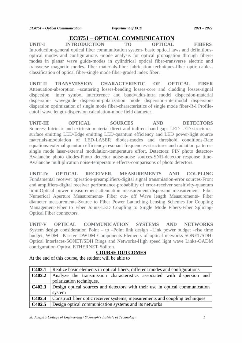
COURSE OUTCOMES At the end of this course, the student will be able to
C402.1 Realize basic elements in optical fibers, different modes and configurations
C402.2 Analyze the transmission characteristics associated with dispersion and
polarization techniques.
C402.3 Design optical sources and detectors with their use in optical communication
system
C402.4 Construct fiber optic receiver systems, measurements and coupling techniques
C402.5 Design optical communication systems and its networks
EC8751 – Optical Communication Department of ECE 2021 – 2022
St. Joseph’s College of Engineering / St Joseph’s Institute of Technology 2
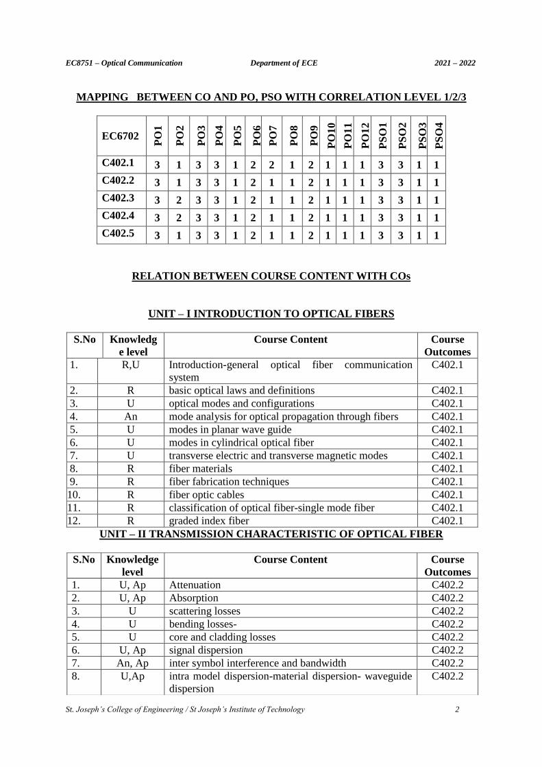
MAPPING BETWEEN CO AND PO, PSO WITH CORRELATION LEVEL 1/2/3
EC6702
PO
1
PO
2
PO
3
PO
4
PO
5
PO
6
PO
7
PO
8
PO
9
PO
10
PO
11
PO
12
PS
O1
PS
O2
PS
O3
PS
O4
C402.1 3 1 3 3 1 2 2 1 2 1 1 1 3 3 1 1
C402.2 3 1 3 3 1 2 1 1 2 1 1 1 3 3 1 1
C402.3 3 2 3 3 1 2 1 1 2 1 1 1 3 3 1 1
C402.4 3 2 3 3 1 2 1 1 2 1 1 1 3 3 1 1
C402.5 3 1 3 3 1 2 1 1 2 1 1 1 3 3 1 1
RELATION BETWEEN COURSE CONTENT WITH COs
UNIT – I INTRODUCTION TO OPTICAL FIBERS
S.No Knowledg
e level
Course Content Course
Outcomes
1. R,U Introduction-general optical fiber communication
system
C402.1
2. R basic optical laws and definitions C402.1
3. U optical modes and configurations C402.1
4. An mode analysis for optical propagation through fibers C402.1
5. U modes in planar wave guide C402.1
6. U modes in cylindrical optical fiber C402.1
7. U transverse electric and transverse magnetic modes C402.1
8. R fiber materials C402.1
9. R fiber fabrication techniques C402.1
10. R fiber optic cables C402.1
11. R classification of optical fiber-single mode fiber C402.1
12. R graded index fiber C402.1
UNIT – II TRANSMISSION CHARACTERISTIC OF OPTICAL FIBER
S.No Knowledge
level
Course Content Course
Outcomes
1. U, Ap Attenuation C402.2
2. U, Ap Absorption C402.2
3. U scattering losses C402.2
4. U bending losses- C402.2
5. U core and cladding losses C402.2
6. U, Ap signal dispersion C402.2
7. An, Ap inter symbol interference and bandwidth C402.2
8. U,Ap intra model dispersion-material dispersion- waveguide
dispersion
C402.2
EC8751 – Optical Communication Department of ECE 2021 – 2022
St. Joseph’s College of Engineering / St Joseph’s Institute of Technology 3
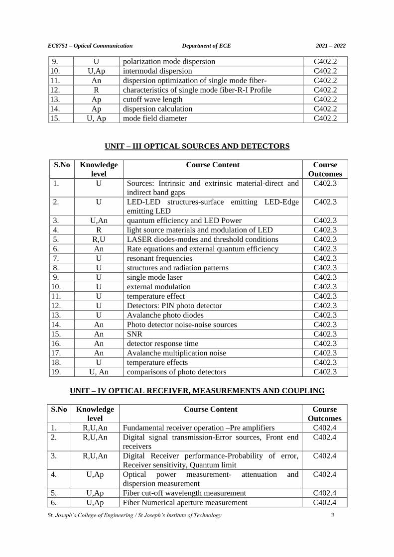
UNIT – III OPTICAL SOURCES AND DETECTORS
S.No Knowledge
level
Course Content Course
Outcomes
1. U Sources: Intrinsic and extrinsic material-direct and
indirect band gaps
C402.3
2. U LED-LED structures-surface emitting LED-Edge
emitting LED
C402.3
3. U,An quantum efficiency and LED Power C402.3
4. R light source materials and modulation of LED C402.3
5. R,U LASER diodes-modes and threshold conditions C402.3
6. An Rate equations and external quantum efficiency C402.3
7. U resonant frequencies C402.3
8. U structures and radiation patterns C402.3
9. U single mode laser C402.3
10. U external modulation C402.3
11. U temperature effect C402.3
12. U Detectors: PIN photo detector C402.3
13. U Avalanche photo diodes C402.3
14. An Photo detector noise-noise sources C402.3
15. An SNR C402.3
16. An detector response time C402.3
17. An Avalanche multiplication noise C402.3
18. U temperature effects C402.3
19. U, An comparisons of photo detectors C402.3
UNIT – IV OPTICAL RECEIVER, MEASUREMENTS AND COUPLING
S.No Knowledge
level
Course Content Course
Outcomes
1. R,U,An Fundamental receiver operation –Pre amplifiers C402.4
2. R,U,An Digital signal transmission-Error sources, Front end
receivers
C402.4
3. R,U,An Digital Receiver performance-Probability of error,
Receiver sensitivity, Quantum limit
C402.4
4. U,Ap Optical power measurement- attenuation and
dispersion measurement
C402.4
5. U,Ap Fiber cut-off wavelength measurement C402.4
6. U,Ap Fiber Numerical aperture measurement C402.4
9. U polarization mode dispersion C402.2
10. U,Ap intermodal dispersion C402.2
11. An dispersion optimization of single mode fiber- C402.2
12. R characteristics of single mode fiber-R-I Profile C402.2
13. Ap cutoff wave length C402.2
14. Ap dispersion calculation C402.2
15. U, Ap mode field diameter C402.2
EC8751 – Optical Communication Department of ECE 2021 – 2022
St. Joseph’s College of Engineering / St Joseph’s Institute of Technology 4
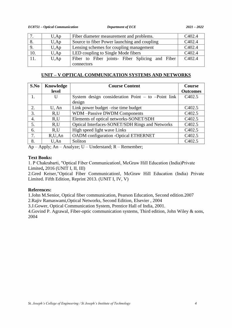
7. U,Ap Fiber diameter measurement and problems. C402.4
8. U,Ap Source to fiber Power launching and coupling C402.4
9. U,Ap Lensing schemes for coupling management C402.4
10. U,Ap LED coupling to Single Mode fibers C402.4
11. U,Ap Fiber to Fiber joints- Fiber Splicing and Fiber
connectors
C402.4
UNIT – V OPTICAL COMMUNICATION SYSTEMS AND NETWORKS
S.No Knowledge
level
Course Content Course
Outcomes
1. U System design consideration Point – to –Point link
design
C402.5
2. U, An Link power budget –rise time budget C402.5
3. R,U WDM –Passive DWDM Components C402.5
4. R,U Elements of optical networks-SONET/SDH C402.5
5. R,U Optical Interfaces-SONET/SDH Rings and Networks C402.5
6. R,U High speed light wave Links C402.5
7. R,U,An OADM configuration -Optical ETHERNET C402.5
8. U,An Soliton C402.5
Ap – Apply; An – Analyze; U – Understand; R – Remember;
Text Books:
1. P Chakrabarti, "Optical Fiber Communication‖, McGraw Hill Education (India)Private
Limited, 2016 (UNIT I, II, III)
2.Gred Keiser,"Optical Fiber Communication‖, McGraw Hill Education (India) Private
Limited. Fifth Edition, Reprint 2013. (UNIT I, IV, V)
References:
1.John M.Senior, Optical fiber communication, Pearson Education, Second edition.2007
2.Rajiv Ramaswami,Optical Networks, Second Edition, Elsevier , 2004
3.J.Gower, Optical Communication System, Prentice Hall of India, 2001.
4.Govind P. Agrawal, Fiber-optic communication systems, Third edition, John Wiley & sons,
2004

EC8751 – Optical Communication Department of ECE 2021 – 2022
St. Joseph’s College of Engineering / St Joseph’s Institute of Technology 5
UNIT I - INTRODUCTION TO OPTICAL FIBERS
PART A – C402.1
1. State Snell’s law. (May 15)
At a material boundary, Snell’s Law gives the angular relationship between a part of the ray
which is reflected at the interface and a part of the ray refracted into the next material.
Where n1, n2 - refractive indicies of first and second medium
2. It is desired to make a single-mode fiber at an operating wavelength=1300 nm with
ncore=1.505 and nclad= 1.502. Find the Numerical Aperture and core radius or core
size (May 14)(Nov 18)
Numerical Aperture = (ncore2 - nclad
2
)1/2 = (1.5052 – 1.5022) 1/2 = 0.094979
Numerical Aperture = v. λ/2πa, v = 2.405,
Core radius (a) = v.λ/2π (Numerical Aperture) = 5239nm.
3. Give the refractive index expression of a graded index fiber. (Dec 06)
n( r ) = n1[ 1-2Δ(r/a)α]1/2 for 0≤ r ≤a
= n1 [ 1-2Δ] 1/2 = n1[ 1 - Δ] = n2 for r ≥ a
4. Define Numerical Aperture of a step index fiber. (Dec 14) (Nov 16) Numerical aperture is the light gathering capability of a fiber. It is related to the refractive
indices of core and cladding. For step index fiber it is expressed as
NA = (ncore 2 - nclad
2)1/2
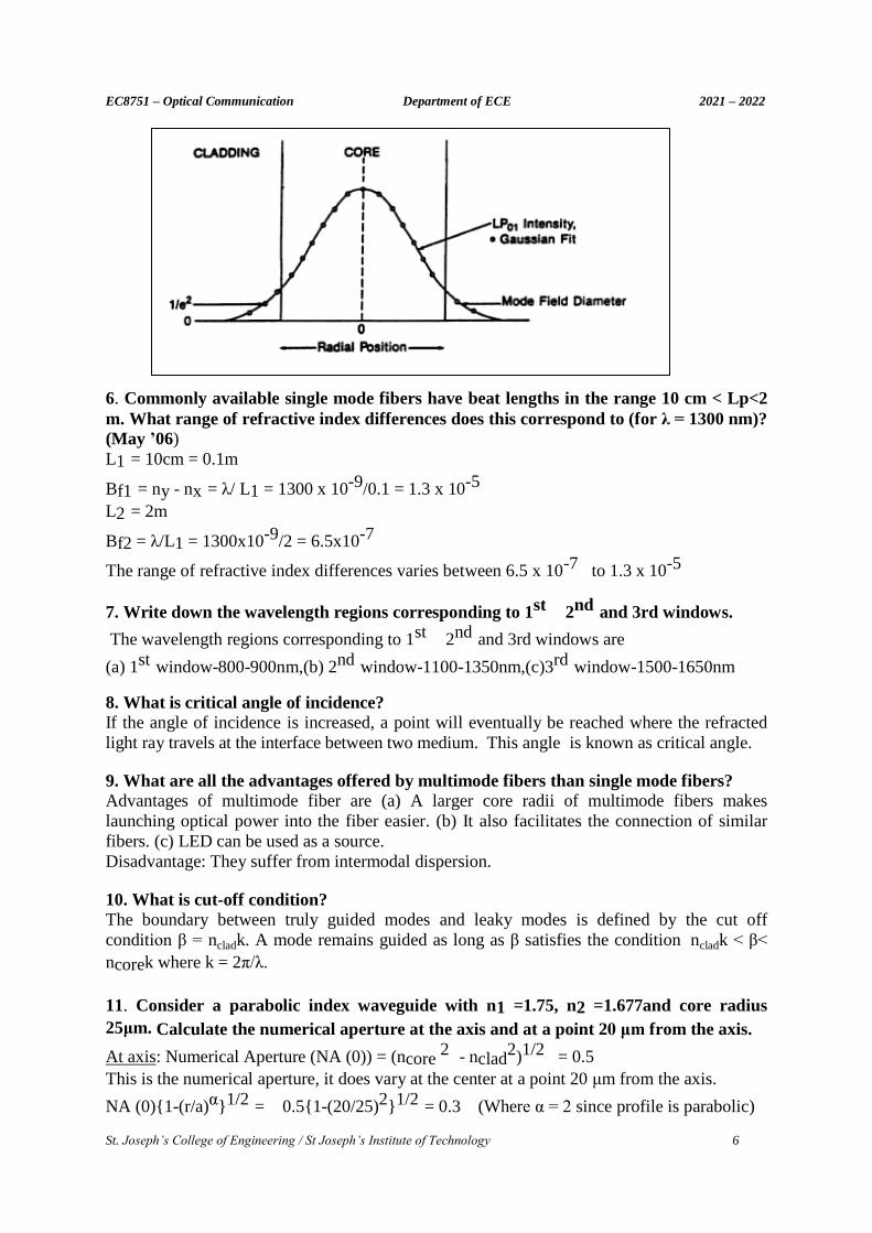
5. Why do we calculate mode field diameter? Write its significance. (Nov 20) Although most light travels inside an optical fiber’s core, the light actually spreads through a
slightly larger volume including the inner edge of the fiber cladding. This effective area is
called the fiber’s mode field diameter or MFD. Mode field diameter is a measure of the
spatial extends of the fundamental mode and it is only important for single mode fibers.
Mode field diameter plays an important role in estimating splice losses, source to fiber
coupler losses, macro bending and micro bending losses, etc. For single mode fibers
manufacturing, MFD is used as a rather more important parameter than fiber’s core size.
2211sinnsinn
EC8751 – Optical Communication Department of ECE 2021 – 2022
St. Joseph’s College of Engineering / St Joseph’s Institute of Technology 6
6. Commonly available single mode fibers have beat lengths in the range 10 cm < Lp<2
m. What range of refractive index differences does this correspond to (for λ = 1300 nm)?
(May ’06)
L1 = 10cm = 0.1m
Bf1 = ny - nx = λ/ L1 = 1300 x 10-9/0.1 = 1.3 x 10⁻⁵
L2 = 2m
Bf2 = λ/L1 = 1300x10-9/2 = 6.5x10⁻⁷
The range of refractive index differences varies between 6.5 x 10⁻⁷ to 1.3 x 10⁻⁵
7. Write down the wavelength regions corresponding to 1st 2nd and 3rd windows.
The wavelength regions corresponding to 1st 2nd and 3rd windows are
(a) 1st window-800-900nm,(b) 2nd window-1100-1350nm,(c)3rd window-1500-1650nm
8. What is critical angle of incidence? If the angle of incidence is increased, a point will eventually be reached where the refracted
light ray travels at the interface between two medium. This angle is known as critical angle.
9. What are all the advantages offered by multimode fibers than single mode fibers?
Advantages of multimode fiber are (a) A larger core radii of multimode fibers makes
launching optical power into the fiber easier. (b) It also facilitates the connection of similar
fibers. (c) LED can be used as a source.
Disadvantage: They suffer from intermodal dispersion.
10. What is cut-off condition? The boundary between truly guided modes and leaky modes is defined by the cut off
condition β = ncladk. A mode remains guided as long as β satisfies the condition ncladk < β<
ncorek where k = 2π/λ.
11. Consider a parabolic index waveguide with n1 =1.75, n2 =1.677and core radius
25μm. Calculate the numerical aperture at the axis and at a point 20 μm from the axis.
At axis: Numerical Aperture (NA (0)) = (ncore 2 - nclad
2)1/2 = 0.5
This is the numerical aperture, it does vary at the center at a point 20 μm from the axis.
NA (0){1-(r/a)α}1/2 = 0.5{1-(20/25)2}1/2 = 0.3 (Where α = 2 since profile is parabolic)
EC8751 – Optical Communication Department of ECE 2021 – 2022
St. Joseph’s College of Engineering / St Joseph’s Institute of Technology 7
12. What are the advantages and disadvantages of the ray optics theory? (Nov 08)
Advantages: (a) Ray optics gives more direct physical interpretation of light propagation
characteristics in an optical fiber. (b) It provides good approximation to the light acceptance
and guiding in fiber at small wavelength unit.
Disadvantages: (a)Ray optics does not predict every mode of curve fiber, (ii) It does not solve
the interference problem. (b)Inaccurate for non-zero wavelength unit when number of guided
mode is large.
13. For a fiber with core refractive index of 1.54 and fractional refractive index
difference of 0.01, calculate its numerical aperture (Nov 13)
n1=1.54, Δ = 0.01
NA = n1 (2Δ)1/2 = 1.54(2 x 0.01)1/2=0.218
14. For n1=1.55 and n2= 1.52, calculate the critical angle and Numerical aperture.
(May 13) (May 15)
NA= (n12-n2
2)1/2 = 0.3035; Critical angle Øc=sin-1(n2/n1) = 17.4o
15. What is a linearly polarized mode? (May 13) In electromagnetics, linear polarization or plane polarization of electromagnetic radiation is a
confinement of the electric field vector or magnetic field vector to a given plane long the
direction of propagation.
16. List any two advantages of single mode fibers. (Nov 14)
The two advantages of single mode fibers are
1. Intermodal dispersion is absent. 2. supports larger bandwidth.
17. Determine the normalized frequency at 820 nm for a step index fiber having a 25µm
radius. The refractive indices of the cladding and core are 1.45 and 1.47 respectively.
How many modes propagate in this fiber at 820nm? (Nov 13)
Normalized frequency is given by, V=(2π/ƛ)(a)(NA)
Numerical Aperture = (ncore 2 - nclad
2)1/2 = (1.472-1.452)1/2 = 0.255
Normalized frequency = (6.18/820nm)(25µm)(0.255)=4.18KHz.
18. Distinguish meridional rays and skew rays. (May 14) (Nov 18)
Meridional rays Skew rays Meridional rays pass through the fiber
axis
Skew rays doesn’t pass through the fiber axis
Meridional rays follows zig zag path Skew rays follow helical path
19. What is total internal reflection in a fiber? (Nov 15) (Nov 16)
Total internal reflection is the phenomenon which occurs when a propagated wave strikes a
medium boundary at an angle larger than a particular critical angle with respect to
the normal to the surface. Where, the critical angle is the angle of incidence for which the
angle of refraction is 90°. The angle of incidence is measured with respect to the normal at
the refractive boundary.
20. What are the conditions for light to get propagated inside a fiber? (Nov 16)
a) Light should travel from denser medium to rarer medium.
b) The angle of incidence should be greater than the critical angle of the denser medium.
EC8751 – Optical Communication Department of ECE 2021 – 2022
St. Joseph’s College of Engineering / St Joseph’s Institute of Technology 8
21. What are the conditions for the single mode propagation? (May ‘16)
Single-mode propagation exists only above a certain specific wavelength called the cut-off
wavelength. Where, the cut-off wavelength is the smallest operating wavelength when SMFs
propagate only the fundamental mode. At this wavelength, the second-order mode becomes
loss and radiates out of the fibre core.
22. What are the advantages of Optical fibre and State the reason to opt for Optical
Fiber Communication. (April 17) (Apr 18)
The following are the major advantages of Optical fibre- wide band, lower loss, light weight,
small size, strength, security, interference immunity and safety. Optical Fiber Communication
have much higher Bandwidth and lower loss.
23. A multimode silica fibre has a core refractive index 1.48 and cladding refractive
index of 1.46. Find the numerical aperture of the fibre. (April 17)
Numerical Aperture = (ncore 2 - nclad
2)1/2 = (1.482 – 1.462 )1/2 = 0.2423
24. Why partial reflection does not suffice the propagation of Light? (Nov 17)
The reason is that, at each reflection a part of the optical energy launched into the optical
fiber would be lost and after a certain distance along the length of the fiber the optical power
would be negligibly low to be of any use. Thus total internal reflection is an absolute
necessity at each reflection for a sustained propagation of optical energy over long
distance e along the optical fiber. This precisely is the sole reason of launching light into the
fiber at particular angles so that light energy propagates along the fiber by multiple
total internal reflections at the core-cladding interface.
25. A graded index optical fiber has a core with a parabolic refractive index profile
which has a diameter of 50 µm. The fiber has a numerical aperture of 0.2. Calculate the
total number of guided modes in the fiber when it is operating at a wavelength of 1 µm.
(Nov 17)
V=(πd/λ)NA = (3.14x50x10-6 /1x10-6)0.2= 785
Total number of guided modes in graded index fiber = V2/4
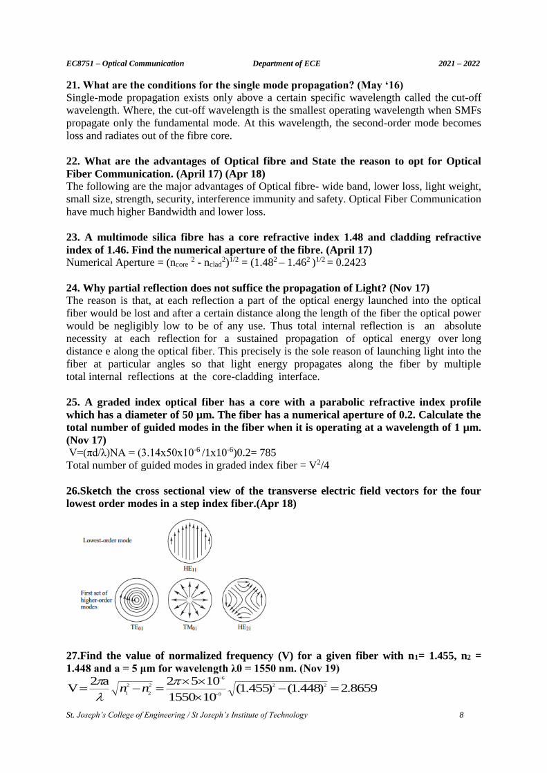
26.Sketch the cross sectional view of the transverse electric field vectors for the four
lowest order modes in a step index fiber.(Apr 18)
27.Find the value of normalized frequency (V) for a given fiber with n1= 1.455, n2 =
1.448 and a = 5 μm for wavelength λ0 = 1550 nm. (Nov 19)
8659.2)448.1()455.1(101550
1052a2V 22
9
6
2
2
2
1
nn
EC8751 – Optical Communication Department of ECE 2021 – 2022
St. Joseph’s College of Engineering / St Joseph’s Institute of Technology 9
28. Give the spectral bands used for optical communication with its name and
designation. (Nov 19)
Original band (O-band): 1260 to 1360 nm
Extended band (E-band): 1360 to 1460 nm
Short band (S-band): 1460 to 1530 nm (shorter than C-band)
Conventional band (C-band): 1530 to 1565 nm (EDFA region)
Long band (L-band): 1565 to 1625 nm (longer than C-band)
Ultra-long band (U-band): 1625 to 1675 nm
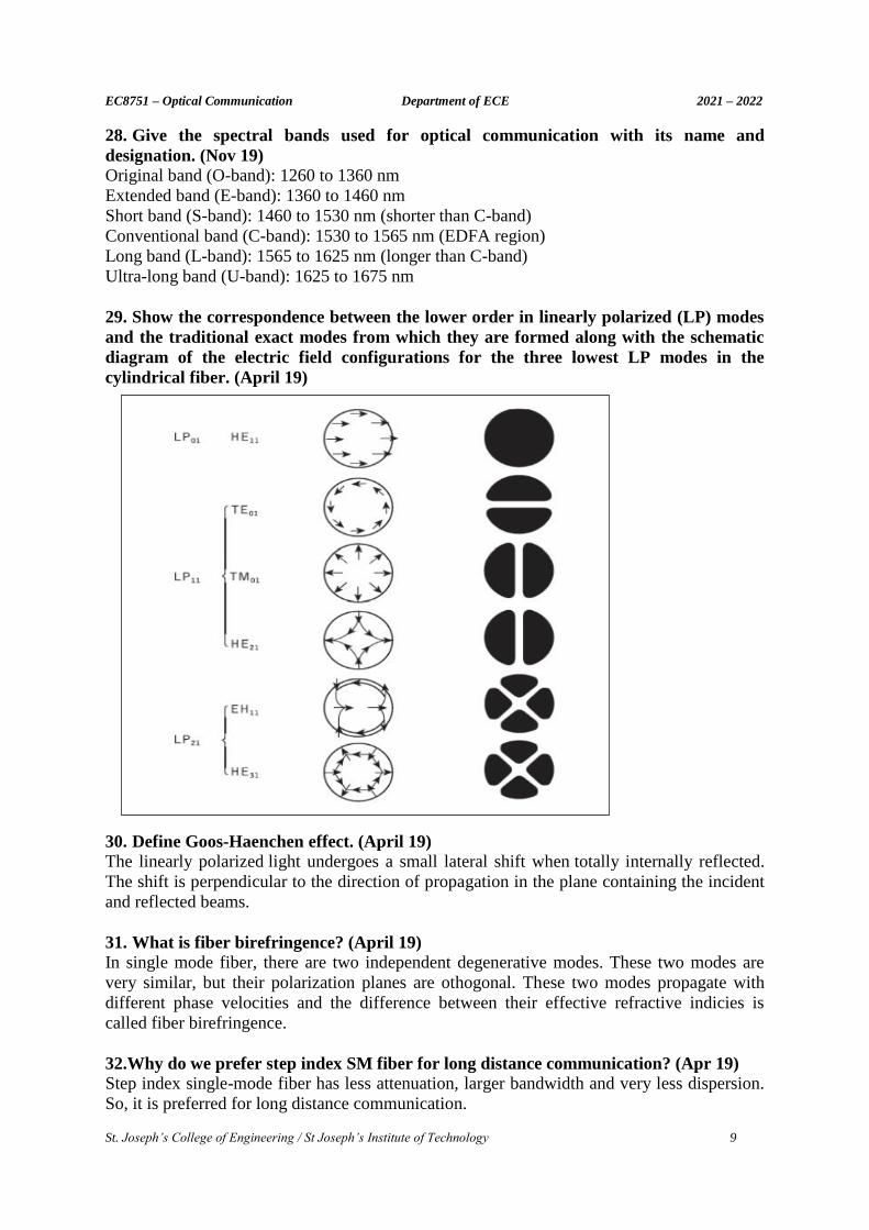
29. Show the correspondence between the lower order in linearly polarized (LP) modes
and the traditional exact modes from which they are formed along with the schematic
diagram of the electric field configurations for the three lowest LP modes in the
cylindrical fiber. (April 19)
30. Define Goos-Haenchen effect. (April 19)
The linearly polarized light undergoes a small lateral shift when totally internally reflected.
The shift is perpendicular to the direction of propagation in the plane containing the incident
and reflected beams.
31. What is fiber birefringence? (April 19)
In single mode fiber, there are two independent degenerative modes. These two modes are
very similar, but their polarization planes are othogonal. These two modes propagate with
different phase velocities and the difference between their effective refractive indicies is
called fiber birefringence.
32.Why do we prefer step index SM fiber for long distance communication? (Apr 19)
Step index single-mode fiber has less attenuation, larger bandwidth and very less dispersion.
So, it is preferred for long distance communication.
EC8751 – Optical Communication Department of ECE 2021 – 2022
St. Joseph’s College of Engineering / St Joseph’s Institute of Technology 10
33.What is the necessity of cladding for an optical fiber? (Apr 19)
a) To provide a lower refractive index at the core interface in order to cause reflection within
the core so that light waves are transmitted through the fiber b) To avoid leakage of light
from fiber c)To provide proper light guidance inside the core d) To provide mechanical
strength to the fiber.
34. What is called as fiber pigtail flylead? (Nov 20)
A fiber pigtail is a single, short, usually tight-buffered, optical fiber that has an optical
connector pre-installed on one end and a length of exposed fiber at the other end. The end of
the pigtail is stripped and fusion spliced to a single fiber of a multi-fiber trunk. Splicing of
pigtails to each fiber in the trunk "breaks out" the multi-fiber cable into its component fibers
for connection to the end equipment.
PART B – C402.1
1. With the neat block diagram, explain the fundamental block of Optical Fiber
Communication. (Apr 18) (Nov 18)
2. i) Derive the expression for numerical aperture of the fiber. ii) A graded index fiber has a
core with a parabolic refractive index profile which has a diameter of 50 μm. The fiber has a
numerical aperture of 0.2. Calculate the total number of guided modes propagating in the
fiber when it is operating at a wavelength of 1 μm. (Apr 19)
3. i) With a neat sketch, illustrate the modes in a planar guide. ii) An optical fiber in air has a
numerical aperture of 0.4. Compare the acceptance angle for meridional rays with that for
skew rays which change direction by 100 degrees at each reflection and also comment on the
result. (Apr 19)
4. Discuss the evolution of fibre optic communication system. (Nov 19)
5. Describe with the aid of simple ray diagram. (i) The multimode step index fiber (ii) The
single mode step index fiber (iii) Compare the advantages and disadvantages of these two
types of fiber for their use as an optical channel. (Nov 19)
6. i) Briefly indicate with the aid of suitable diagrams the difference between meriodinal and
skew ray paths in step index fibers. Derive an expression for the acceptance angle for a skew
ray which changes direction by an angle 2γ at each reflection in a step index fiber in term of
the fiber NA and γ. It may be assumed that ray theory holds for the fiber. ii) A step index
fiber with suitably large core diameter for ray theory considerations has core and cladding
refractive indices of 1.44 and 1.42 respectively. Calculate the acceptance angle for skew rays
which change direction by 150 degrees at each reflection. (Nov 19)
7. A silica fiber with core diameter large enough to be considered by ray theory analysis has a
core refractive index of 1.50 and cladding refractive index of 1.47. Determine (a) The critical
angle at the core cladding interface (b) The NA for the fiber (c) The acceptance angle in air
for the fiber. (Apr 18)
8. A step index fiber with numerical aperture of 0.2 supports approximately 1000 modes at an
850nm wavelength. What is the diameter of its core? How many modes does the fiber
supports at 850nm and 1550nm? (Apr 19)
9. (i) Find the core radius necessary for single mode operation at 1320nm of a step index fiber
with n1=1.48 and n2=1.478. Determine NA and acceptance angle of the fiber? (ii) Derive the
wave equation for cylindrical fiber. (Apr 17)
EC8751 – Optical Communication Department of ECE 2021 – 2022
St. Joseph’s College of Engineering / St Joseph’s Institute of Technology 11
10. Consider a multimode fiber that has a core refractive index of 1.480 and a core cladding
index difference of 2%. Find the numerical aperture, the acceptance angle and the critical
angle of the fiber. (Nov 18)
11. i)Explain in detail about linearly polarised modes in optical fibers and their relationship to
V number.ii)Consider a fiber with 25 µm core radius, core index n1 = 1.48 and Δ = 0.01. If λ
= 1320 nm, what value of V and how many modes propagate in the fiber. What percent of
optical power flows in the cladding? If the core cladding difference is reduced to Δ = 0.003,
how many modes does the fiber support and what fraction of the optical power flows in the
cladding?(Apr 19)
12. i) Draw and explain refractive index profile and ray transmission in multimode step index
fiber and single mode step index fiber. ii) Consider a multimode step index fiber with a 62.5
µm core diameter and a core cladding index difference of 1.5%.If the core refractive index is
1.480, estimate the normalized frequency of the fiber and the total no of modes supported in
the fiber at the wavelength of 850 nm. (Apr 19)
13. i) Suppose that an incoming ray from a light source is not within the acceptance angle
limits. What will happen to the light to be transmitted ? Suggest a proper solution so that the
whole of information to be transmitted is properly sent through the fiber. (Nov 20)
ii) Step index fiber has an acceptance angle of 18 degrees in air. The fiber has a relative
refractive index difference of 2.5%. Estimate the value of the critical angle at the core-cladding
interface of the fiber and also the NAof the fiber. (Nov 20)
14. i) Explain about any two fiber fabrication techniques. (Nov 20)
ii) Calculate the value of critical angle (with respect to the interface) when light travels from
glass (n1 = 1.5) into water (n2 = 1.33). What is the value of critical angle with respect to the
normal drawn on the interface plane at the point of incidence? (Nov 20)
UNIT-II TRANSMISSION CHARACTERISTICS OF OPTICAL FIBER
PART A – C402.2
1. Define signal attenuation. (Nov 13) (May 15) (Nov 17) Signal attenuation is defined as the ratio of the optical output power Pout from a fiber of
length L to the optical input power Pin. Attenuation (α) = 10/L log {Pin/Pout} dB/Km
2. What are the causes of absorption? (Nov 16) Absorption is caused by 3 different mechanisms. (a) Absorption by atomic defects in the glass
composition. (b) Extrinsic absorption by impurity atoms in the glass material. (c)Intrinsic
absorption by the basic constituent atoms of the material.
3. What are the types of bends that can be subjected to a fiber? (May 15)
Two types of bends are (i) Macroscopic bends having radii that are larger compared to the
fiber diameter. (ii) Random microscopic bends of the fiber axis that can arise when the fibers
are incorporated into cables.
4. How does intrinsic absorption occur? (Nov 14) (Nov 16)
The intrinsic absorption occurs when the material is in perfect state with no density
variations, impurities, material inhomogeneity etc. Intrinsic absorption thus sets the
fundamental lower limit on absorption for any particular material.

EC8751 – Optical Communication Department of ECE 2021 – 2022
St. Joseph’s College of Engineering / St Joseph’s Institute of Technology 12
5. Identify the causes of scattering loss. (May 14)
Scattering losses in glass arise from microscopic variations in the material
density, from compositional fluctuations, and from structural inhomogenities or defects
occurring during fiber manufacture.
6. How can you minimize micro bending losses? Micro bending losses can be minimized by extruding a compressible jacket over the
fiber. When external forces are applied to this configuration, the jacket will be deformed, but
the fiber will tend to stay relatively straight.
7. How does waveguide dispersion occur? Waveguide dispersion occurs because a single mode fiber only confines about 80% of
the optical power to the core. The 20% of the optical power travels in the cladding
because of the speed difference between these two dispersion occurs.
8. List the basic attenuation mechanisms in an optical fiber. (Dec 14) 1. Absorption, 2.Scattering, 3.Radiative losses of the optical energy 4. Bending Losses are the
basic attenuation mechanism in an optical fiber.
9. What is Rayeligh Scattering? (May 13)
This scattering occurs in all directions and produces attenuation proportional to 1/ ƛ4. This
loss occurs in the ultra violet region. It tail extends up to infrared region.
10. What is Mode Coupling? It is another type of pulse distortion which is common in o p tical links. The pulse
distortion will increase less rapidly after a certain initial length of fiber due to this mode
coupling and differential mode losses. In initial length coupling of energy from one mode to
another arises because of structural irregularities, fiber diameter etc.
11. What is elastic and inelastic scattering? (Apr 18)
Linear scattering(i.e. Rayleigh), which is said to be elastic because the scattered wave has the
same frequency as the incident wave, whereas nonlinear scattering process are inelastic.
12. Distinguish between Intramodal and Intermodal Dispersion. (Nov 18)
Intramodal Dispersion Intermodal Dispersion
Pulse broadening within a single mode is called
as intramodal dispersion or chromatic
dispersion.
Dispersion caused by multipath propagation
of light energy is referred to as intermodal
dispersion.
It occurs in Single Mode Fiber It occurs in Multimode fiber
13. What do you mean by polarization mode dispersion in a fiber? (Nov 15) (Nov
16)(Apr 18)(Nov 18) The difference in propagation times between the two orthogonal polarization modes will
result in pulse spreading. This is called as polarization Mode Dispersion.
14. What do you understand by phase and group velocity? (May 16)
The group velocity is the velocity with which the envelope of a pulse propagates in a
medium, assuming a long pulse with narrow and the absence of nonlinear effects
EC8751 – Optical Communication Department of ECE 2021 – 2022
St. Joseph’s College of Engineering / St Joseph’s Institute of Technology 13
The phase velocity of light is the velocity with which phase fronts propagate in a medium. It
is related to the wave number ( ) and the (angular) optical frequency ( ),
15. What is chromatic dispersion? (May 16)
The chromatic dispersion of an optical medium is the phenomenon that the phase
velocity and group velocity of light propagating in a transparent medium depend on
the optical frequency; that dependency results mostly from the interaction of light with
electrons of the medium.
16. What are atomic defects? Atomic defects are imperfections of the atomic structure of the fiber material such as missing
molecules, high density clusters of atom groups, or oxygen defects in the glass structure.
17. How does impurity absorption loss occur? Impurity absorption loss occurs either because of electronic transitions between the
energy levels associated with the incompletely filled inner sub shell of these ions or
because of charge transitions from one ion to another.
18. What is effective cut-off wavelength? It is defined as the largest wavelength at which the higher order LP11 mode power relative to
the fundamental LP01 mode power is reduced to 0.1db.
19. What’s Urbach’s rule? The UV edges of the electron absorption bands of both amorphous and crystalline materials
follow the empirical relationship, αUV=CeE/E0 which’s known as Urbach’s rule. Here C
and E0 are empirical constants and E is the photon energy.
20. What are micro bends? How are they caused in the fiber? Micro bends are repetitive small-scale fluctuations in the radius of curvature of the fiber
axis. They are caused either by non- uniformities in the manufacturing of the fiber or by
non- uniform lateral pressures created during the cabling of the fiber.
21. What is intermodal dispersion? (April 17)
Intermodal dispersion is also called modal dispersion and is the phenomenon that the group
velocity of light propagating in a multi-mode fiber or other waveguide depends not only on
the optical frequency but also on the propagation mode involved. Other ways it is a time or
arrival differences of signal between Zero Order and highest order modes.
22. A manufacturer’s data sheet lists the material dispersion Dmat=110ps/nm.km at a
wavelength of 860 nm. Find the RMS pulse broadening per Km due to material
dispersion if the optical source has a spectral width = 40 nm at b an output wavelength
of 860nm. (Nov 17)
The RMS of material dispersion σmat/L= σλDmat =(40nm)x(110ps/(nm.km)) = 4.4 ns/km.
23.A fiber has an attenuation of 0.5 dB/Km at 1500 nm. If 0.5 mW of optical power is
initially launched into the fiber, estimate the power level after 25 km. (Apr 19) (Nov 19)
EC8751 – Optical Communication Department of ECE 2021 – 2022
St. Joseph’s College of Engineering / St Joseph’s Institute of Technology 14
Kmin distance - z dB,in n attenuatio
PPin(dbm)out(dbm)
z
dBm 8.12255.0101
105.0log10P
3
3
out(dbm)
24.A manufacturer’s data sheet lists the material dispersion Dmat of GeO2 doped fiber
to be 210 ps/(nm km) at a wavelength of 860 nm. Find the rms pulse broadening per km
due to material dispersion if the optical source is a GaAIAs LED that has spectral width
σλ of 40 nm at an output wavelength of 860 nm. (Nov 19)
ns/km 8.4(ps/nm.km) 210 nm 40DKm/matmat
25.When the mean optical power launched into a 8 Km fiber is 120 μw. The mean
optical power at the fiber output is 3 μw. Calculate the overall attenuation in dB
assuming there are no splices. (Apr 19)
2.002516.02/8(dB/Km)n attenuatio
02.16101
10120log10
101
10120log10PP(dB)n attenuatio
6
6
6
6
out(dBm)in(dbm)
26. Give the measure of information capacity in optical waveguide. (Apr 19)
Measure of information capacity in optical waveguide is specified by bandwidth distance
product.
27. A continuous 12 km long optical fiber link has a loss of 1.5 dB/Km. Propose a proper
solution to find the minimum optical power that must be launched into the fiber to
maintain the optical power level of 0.3 μw at the receiving end.(Nov 20)
Given: L= 12km, α = 1.5dB/km, Po = 0.3 μw
= 18.92 μw
28. Consider a single mode fiber having core refractive index n1 = 1.5. The fiber length
is 12 meter. Find the time taken by the axial ray to travel along the fiber. (Nov 20)
Tmin = Ln1/c = (12)(1.5)/3x108
= .06µs
PART B – C402.2
1. Explain in detail with necessary mathematical expressions the various attenuation
mechanisms in optical fiber. (Nov 18) (Apr 18)
2. When the mean optical power launched into an 8km length of fiber is 120μW, the mean
optical power at the fiber output is 3 μW. Determine (a) Overall signal attenuation in dB/km
(b) The overall signal attenuation for a 10 km optical link using the same fiber with splices at
1Km intervals, each giving an attenuation of 1dB. (c) Numerical input/output power ratio.
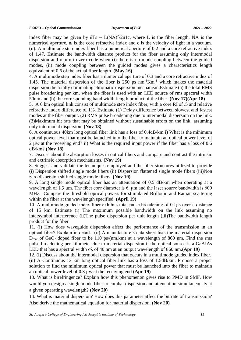
(Apr 18) 3. (i) Describe the mechanism of intermodal dispersion in a multimode step index fiber. Show
that the total broadening of a light pulse due to intermodal dispersion in multimode step
kmdBP
P
L o
i /log10
10
EC8751 – Optical Communication Department of ECE 2021 – 2022
St. Joseph’s College of Engineering / St Joseph’s Institute of Technology 15
index fiber may be given by δTs = L(NA)2/2n1c, where L is the fiber length, NA is the
numerical aperture, ni is the core refractive index and c is the velocity of light in a vacuum.
(ii). A multimode step index fiber has a numerical aperture of 0.2 and a core refractive index
of 1.47. Estimate the bandwidth distance product for the fiber assuming only intermodal
dispersion and return to zero code when (i) there is no mode coupling between the guided
modes, (ii) mode coupling between the guided modes gives a characteristics length
equivalent of 0.6 of the actual fiber length. (May 16)
4. A multimode step index fiber has a numerical aperture of 0.3 and a core refractive index of
1.45. The material dispersion of the fiber is 250 ps nm-1Km-1 which makes the material
dispersion the totally dominating chromatic dispersion mechanism.Estimate (a) the total RMS
pulse broadening per km. when the fiber is used with an LED source of rms spectral width
50nm and (b) the corresponding band width-length product of the fiber. (Nov 17)(Apr 18)
5. A 6 km optical link consist of multimode step index fiber, with a core RI of .5 and relative
refractive index difference of 1%. Estimate (1) Delay difference between slowest and fastest
modes at the fiber output. (2) RMS pulse broadening due to intermodal dispersion on the link.
(3)Maximum bit rate that may be obtained without sustainable errors on the link assuming
only intermodal dispersion. (Nov 18)
6. A continuous 40km long optical fiber link has a loss of 0.4dB/km i) What is the minimum
optical power level that must be launched into the fiber to maintain an optical power level of
2 µw at the receiving end? ii) What is the required input power if the fiber has a loss of 0.6
dB/km? (Nov 18)
7. Discuss about the absorption losses in optical fibers and compare and contrast the intrinsic
and extrinsic absorption mechanisms. (Nov 19)
8. Suggest and validate the techniques employed and the fiber structures utilized to provide
(i) Dispersion shifted single mode fibers (ii) Dispersion flattened single mode fibers (iii)Non
zero dispersion shifted single mode fibers. (Nov 19)
9. A long single mode optical fiber has an attenuation of 0.5 dB/km when operating at a
wavelength of 1.3 μm. The fiber core diameter is 6 μm and the laser source bandwidth is 600
MHz. Compare the threshold optical powers for stimulated Brillouin and Raman scattering
within the fiber at the wavelength specified. (April 19)
10. A multimode graded index fiber exhibits total pulse broadening of 0.1μs over a distance
of 15 km. Estimate (i) The maximum possible bandwidth on the link assuming no
intersymbol interference (ii)The pulse dispersion per unit length (iii)The bandwidth length
product for the fiber
11. (i) How does waveguide dispersion affect the performance of the transmission in an
optical fiber? Explain in detail. (ii) A manufacture’s data sheet lists the material dispersion
Dmat of GeO2 doped fiber to be 110 ps/(nm.km) at a wavelength of 860 nm. Find the rms
pulse broadening per kilometer due to material dispersion if the optical source is a GaAIAs
LED that has a spectral width σλ of 40 nm at an output wavelength of 860 nm.(Apr 19)
12. (i) Discuss about the intermodal dispersion that occurs in a multimode graded index fiber.
(ii) A Continuous 12 km long optical fiber link has a loss of 1.5dB/km. Propose a proper
solution to find the minimum optical power that must be launched into the fiber to maintain
an optical power level of 0.3 µw at the receiving end (Apr 19)
13. What is birefringence? Explain how this phenomenon gives rise to PMD in SMF. How
would you design a single mode fiber to combat dispersion and attenuation simultaneously at
a given operating wavelength? (Nov 20)
14. What is material dispersion? How does this parameter affect the bit rate of transmission?
Also derive the mathematical equation for material dispersion. (Nov 20)

EC8751 – Optical Communication Department of ECE 2021 – 2022
St. Joseph’s College of Engineering / St Joseph’s Institute of Technology 16
UNIT III OPTICAL SOURCES AND DETECTORS
PART A – C402.3
1. What are the laser light properties? How are they produced?
Laser light properties are 1. High radiance output, 2.Fast emission response time
3. High quantum efficiency. Dimensional characteristics compatible with those of optical
fibers. High radiance and high quantum efficiency are achieved through carrier and
optical confinement using double hetero structure.
2. What are the mechanisms behind lasing action? (Nov 16)
Laser action is the result of three key processes Photon absorption, Spontaneous emission and
Stimulated emission. The conditions to achieve laser action are (i) Magnitude of guided mode
should be greater than the threshold value, (ii) At the lasing threshold, a steady state
oscillation takes place, and (iii) the magnitude and phase of the returned wave must be
equal to those of the original wave.
3. What are direct band gap and indirect band semiconductors? In direct band gap materials direct transition is possible from valence band to
conduction band. e.g. GaAs, InP, InGaAs, In indirect band gap materials direct transition is
not possible from valence band to conduction. e.g. Silicon, germanium.
4. Define internal quantum efficiency of a LED (Nov 14, May 14, Nov 15, Nov 18) The internal quantum efficiency in the active region is the fraction of electron hole pairs
thatrecombine radiatively. It’s given by ηi=Rr / (Rr + Rnr)
Where, ηi is the internal quantum efficiencyr is the radiative recombination per unit volume.
Rnr is the non-radiative recombination rate.
5. Why do we prefer laser diodes over LED’s for communication applications? 1. High intensity radiation 2 . Narrow spectral width of the laser source, are the preferable
features of Laser compared to LED.
6.. What is meant by hetero junction structure? (Nov 15) To achieve carrier and optical confinement, two different alloy layers on each side of active
region is known as hetero junction structure.
7. What are the factors that determine the response time of photo detector? (Apr 18)
i) The transit time of the photo carriers in the depletion region.
ii) The diffusion time of the photo carriers generated outside the depletion region. iii)The RC
time constant of the photodiode and its associated circuit.
8. Write two differences between an ILD and a LED. (May 16)(April 17)
S.No LED ILD 1. Optical output is in coherent Optical output is coherent 2. Output radiation has broad spectral width Highly Monochromatic
EC8751 – Optical Communication Department of ECE 2021 – 2022
St. Joseph’s College of Engineering / St Joseph’s Institute of Technology 17
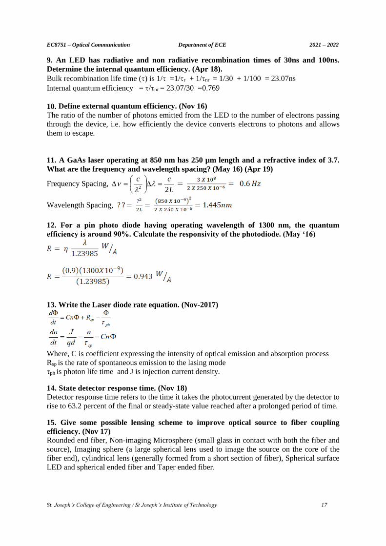
9. An LED has radiative and non radiative recombination times of 30ns and 100ns.
Determine the internal quantum efficiency. (Apr 18).
Bulk recombination life time () is 1/ =1/r + 1/nr = 1/30 + 1/100 = 23.07ns
Internal quantum efficiency = /nr = 23.07/30 =0.769
10. Define external quantum efficiency. (Nov 16)
The ratio of the number of photons emitted from the LED to the number of electrons passing
through the device, i.e. how efficiently the device converts electrons to photons and allows
them to escape.
11. A GaAs laser operating at 850 nm has 250 µm length and a refractive index of 3.7.
What are the frequency and wavelength spacing? (May 16) (Apr 19)
Frequency Spacing, L
cc
22
Wavelength Spacing,
12. For a pin photo diode having operating wavelength of 1300 nm, the quantum
efficiency is around 90%. Calculate the responsivity of the photodiode. (May ‘16)
13. Write the Laser diode rate equation. (Nov-2017)
Where, C is coefficient expressing the intensity of optical emission and absorption process
Rsp is the rate of spontaneous emission to the lasing mode
τph is photon life time and J is injection current density.
14. State detector response time. (Nov 18)
Detector response time refers to the time it takes the photocurrent generated by the detector to
rise to 63.2 percent of the final or steady-state value reached after a prolonged period of time.
15. Give some possible lensing scheme to improve optical source to fiber coupling
efficiency. (Nov 17)
Rounded end fiber, Non-imaging Microsphere (small glass in contact with both the fiber and
source), Imaging sphere (a large spherical lens used to image the source on the core of the
fiber end), cylindrical lens (generally formed from a short section of fiber), Spherical surface
LED and spherical ended fiber and Taper ended fiber.
EC8751 – Optical Communication Department of ECE 2021 – 2022
St. Joseph’s College of Engineering / St Joseph’s Institute of Technology 18
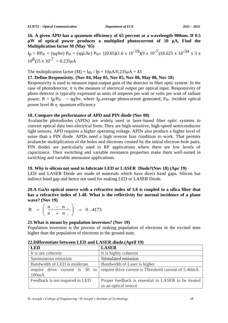
16. A given APD has a quantum efficiency of 65 percent at a wavelength 900nm. If 0.5
μW of optical power produces a multiplied photocurrent of 10 μA, Find the
Multiplication factor M (May ’05)
Ip = RPo = (ηq/hv) Po = (ηqλ/hc) Po= {(0.65)(1.6 x 10⁻¹⁹)(9 x 10⁻⁷)/(6.625 x 10-34 x 3 x
108)}5 x 10-7 = 0.235μA
The multiplication factor (M) = Im / Ip = 10μA/0.235μA = 43
17. Define Responsivity. (Nov 04, May 05, Nov 05, Nov 08, May 08, Nov 18)
Responsivity is used to measure input-output gain of the detector in fiber optic system. In the
case of photodetector, it is the measure of electrical output per optical input. Responsivity of
photo detector is typically expressed as units of amperes per watt or volts per watt of radiant
power. R = Ip/Po = ηq/hν, where Ip-average photocurrent generated, Po- incident optical
power level & η -quantum efficiency
18. Compare the performance of APD and PIN diode (Nov 08) Avalanche photodiodes (APDs) are widely used in laser-based fiber optic systems to
convert optical data into electrical form. They are high-sensitive, high-speed semiconductor
light sensors. APD requires a higher operating voltage. APDs also produce a higher level of
noise than a PIN diode. APDs need a high reverse bias condition to work. That permits
avalanche multiplication of the holes and electrons created by the initial electron-hole pairs.
PIN diodes are particularly used in RF applications where there are low levels of
capacitance. Their switching and variable resistance properties make them well-suited in
switching and variable attenuator applications.
19. Why is silicon not used to fabricate LED or LASER Diode?(Nov 18) (Apr 19)
LED and LASER Diode are made of materials which have direct band gaps. Silicon has
indirect band gap and hence not used for making LED or LASER Diode.
20.A GaAs optical source with a refractive index of 3.6 is coupled to a silica fiber that
has a refractive index of 1.48. What is the reflectivity for normal incidence of a plane
wave? (Nov 19)
4173.0nn
nnR
2
21
21
21.What is meant by population inversion? (Nov 19)
Population inversion is the process of making population of electrons in the excited stste
higher than the population of electrons in the ground state.
22.Differentiate between LED and LASER diode.(April 19)
LED LASER
It is not coherent It is highly coherent
Spontaneous emission Stimulated emission
Bandwidth of LED is moderate Bandwidth of Laser is higher
require drive current is 50 to
100mA
require drive current is Threshold current of 5-40mA
Feedback is not required in LED Proper feedback is essential in LASER to be treated
as an optical source
EC8751 – Optical Communication Department of ECE 2021 – 2022
St. Joseph’s College of Engineering / St Joseph’s Institute of Technology 19
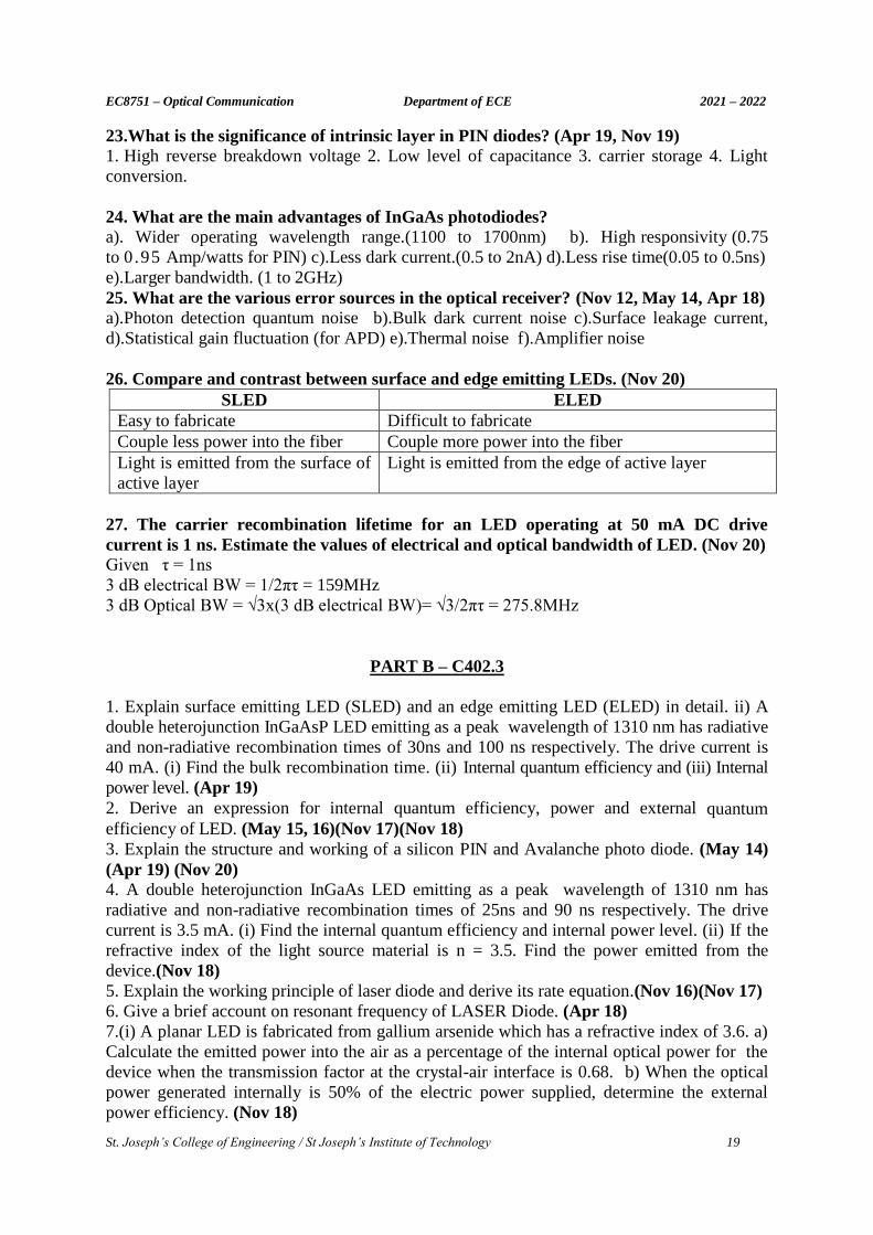
23.What is the significance of intrinsic layer in PIN diodes? (Apr 19, Nov 19) 1. High reverse breakdown voltage 2. Low level of capacitance 3. carrier storage 4. Light
conversion.
24. What are the main advantages of InGaAs photodiodes? a). Wider operating wavelength range.(1100 to 1700nm) b). High responsivity (0.75
to 0 .95 Amp/watts for PIN) c).Less dark current.(0.5 to 2nA) d).Less rise time(0.05 to 0.5ns)
e).Larger bandwidth. (1 to 2GHz)
25. What are the various error sources in the optical receiver? (Nov 12, May 14, Apr 18) a).Photon detection quantum noise b).Bulk dark current noise c).Surface leakage current,
d).Statistical gain fluctuation (for APD) e).Thermal noise f).Amplifier noise
26. Compare and contrast between surface and edge emitting LEDs. (Nov 20)
SLED ELED
Easy to fabricate Difficult to fabricate
Couple less power into the fiber Couple more power into the fiber
Light is emitted from the surface of
active layer
Light is emitted from the edge of active layer
27. The carrier recombination lifetime for an LED operating at 50 mA DC drive
current is 1 ns. Estimate the values of electrical and optical bandwidth of LED. (Nov 20)
Given τ = 1ns
3 dB electrical BW = 1/2πτ = 159MHz
3 dB Optical BW = √3x(3 dB electrical BW)= √3/2πτ = 275.8MHz
PART B – C402.3
1. Explain surface emitting LED (SLED) and an edge emitting LED (ELED) in detail. ii) A
double heterojunction InGaAsP LED emitting as a peak wavelength of 1310 nm has radiative
and non-radiative recombination times of 30ns and 100 ns respectively. The drive current is
40 mA. (i) Find the bulk recombination time. (ii) Internal quantum efficiency and (iii) Internal
power level. (Apr 19)
2. Derive an expression for internal quantum efficiency, power and external quantum
efficiency of LED. (May 15, 16)(Nov 17)(Nov 18)
3. Explain the structure and working of a silicon PIN and Avalanche photo diode. (May 14)
(Apr 19) (Nov 20) 4. A double heterojunction InGaAs LED emitting as a peak wavelength of 1310 nm has
radiative and non-radiative recombination times of 25ns and 90 ns respectively. The drive
current is 3.5 mA. (i) Find the internal quantum efficiency and internal power level. (ii) If the
refractive index of the light source material is n = 3.5. Find the power emitted from the
device.(Nov 18)
5. Explain the working principle of laser diode and derive its rate equation.(Nov 16)(Nov 17)
6. Give a brief account on resonant frequency of LASER Diode. (Apr 18)
7.(i) A planar LED is fabricated from gallium arsenide which has a refractive index of 3.6. a)
Calculate the emitted power into the air as a percentage of the internal optical power for the
device when the transmission factor at the crystal-air interface is 0.68. b) When the optical
power generated internally is 50% of the electric power supplied, determine the external
power efficiency. (Nov 18)
EC8751 – Optical Communication Department of ECE 2021 – 2022
St. Joseph’s College of Engineering / St Joseph’s Institute of Technology 20
8. When a current pulse is applied to a laser diode, the injected carrier pair density n within
the recombination region of width ‘d’ changes with time according to the relationship.
dn/dt = J/qd - n/r (i) Assume r is the average carrier lifetime in th recombination region
when the injected carrier pair density is nth near the threshold current density Jth . That is in the
steady state we have δn/δt=0, so that nth = Jthτ/qd. If a current pulse of amplitude Ip is
applied to an unbiased laser diode, show that the time needed for the onset of stimulated
emission is td = τ ln [Ip/(Ip-Ith)]. Assume the drive current I=JA, where J is the current
density and A is the area of the active region. (ii) If the laser is now pre-biased to a current
density JB = IB/A, so that the initial excess carrier pair density is nB=JBτ/qd, then the current
density in the active region during a current pulse Ip is J=JB+JP. Show that in this case td =
τ ln [Ip/(Ip+(IB-Ith))] (Nov 18)
9. Draw and explain the different structures used to achieve carrier and optical confinement
in laser diodes. (Nov 19)
10.Discuss the necessary expressions that different types of noises that affect the performance
of a photo detector. (Nov 19)
11. Describe with the aid of suitable diagrams the mechanism giving the emission of light
from a LED. Discuss the effects of this mechanism on the properties of the LED in relation to
its use as an optical source for communication. (Nov 19)
12. (i) Discuss the principle of gain guided laser and index guided laser diodes along with the
schematic diagram. (ii) When 3×10¹¹ photons each with a wavelength of 0.85 μm are incident
on a photodiode, on average 1.2×10¹¹ electrons are collected at the terminals of the device.
Determine the quantum efficiency and the responsivity of the photodiode at 0.85 μm. (Apr
19) 13. i)Demonstrate the structure and working of silicon Avalanche photodiode. (ii) The
radiative and nonradiative recombination lifetimes of the minority carriers in the active
region of a double-hetrojunction LED are 60 ns and 100ns respectively. Determine the total
carrier recombination lifetime and the power internally generated within the device when the
peak emission wavelength is 0.87 μm at a drive current of 40 mA. (Apr 19)
14. Draw and explain the structure of Fabry Perot resonator cavity for a laser diode. Derive
laser diode rate equation (Apr 19)
15. (i)With a schematic of double heterojunction LED explain how carrier confinement and
optical confinement can be achieved simultaneously.
(ii) Define quantum efficiency of an LED. Derive an expression for internal quantum
efficiency of an LED and hence discuss the effect of various recombination mechanisms on
the quantum efficiency. (Nov 20)
16. (i) Derive Laser diode rate equation.
(ii) A GaAs laser operating at 850 nm has 500 μm length and a refractive index n = 3.7. a)
What are its frequency spacing and wavelength spacing ? b) If at the half power point λ – λ0
= 2 nm, what is the spectral width of the gain ? (Nov 20)
UNIT IV- OPTICAL RECEIVER, MEASUREMENTS AND COUPLING
PART A – C402.4
1. What are the requirements for a preamplifier? a). Preamplifier bandwidth must be greater than or equal to signal bandwidth. b).It must
reduce all source of noise, c).It must have high receiver sensitivity.
EC8751 – Optical Communication Department of ECE 2021 – 2022
St. Joseph’s College of Engineering / St Joseph’s Institute of Technology 21
2. Why do we prefer trans-impedance preamplifier rather than high impedance
preamplifier? (Nov 14) Since the high impedance produces large input RC time constant, the front end bandwidth is
less than the signal bandwidth. This drawback is overcome in the trans-impedance
preamplifier.
3. Define receiver Sensitivity. (Nov 17)
Receiver sensitivity is the lowest power level at which the receiver can detect an RF signal
and demodulate data. Sensitivity is purely a receiver specification and is independent of the
transmitter.
4. Define quantum limit. (May 14, Nov 13, May 16, Apr 18, Apr 19) The minimum received optical power required for a specific bit error rate performance
in a digital system is known as quantum limit.
5. Distinguish between splice and connector.
SPLICE CONNECTOR 1. A permanent joint between two
optical fibers.
A demountable joint between two fibers.
2. It is used to establish long-haul optical
fiber links where smaller fiber lengths need
to be joined, and there is no requirement for
repeated connection and disconnection.
The connector design must allow for repeated
connection and disconnection without problems
of fiber alignment, which may lead to
degradation in the performance of the
transmission line at the joint.
6. Define BER. (May 15) (Nov 16) (April 17) The number ( Ne) of errors occurring over a certain time interval ( t) divided by the
number of pulses transmitted (Nt) during this interval is called as the error rate or the bit
error rate. Bit error rate, BER =Ne/Nt
7. What are connectors? What are the types of connectors?
The connectors are used to join the optical sources as well as detectors to the optical fiber
temporarily. They are also used to join two optical fibers. The 2 major types of connectors
are:1. Lensed type expanded beam connector 2. Ferrule type connector
8. What are the requirements of a good connector? The requirements of a good connector are as follows:
1. Low loss 2. Repeatability 3. Predictability 4. Ease of assembly and use 5. Low cost &
reliability 6 . Compatibility
9. Mention the different techniques used for measurement of fiber refractive profile.
The different techniques used for measurement of fiber refractive profile are
(a). Interferometric Method, (b). Near field scanning method, (c) Refractive near field method
10. What are the methods of fiber splicing? (Nov/Dec 2020)
There are 3 methods of fiber splicing. They are:
1. Electric arc fusion splicing or fusion splicing 2. Mechanical splicing
3. V-groove splicing or loose tube splicing
EC8751 – Optical Communication Department of ECE 2021 – 2022
St. Joseph’s College of Engineering / St Joseph’s Institute of Technology 22
11. Mention types of preamplifiers.
Types of preamplifiers are
(a) Low impedance preamplifiers, (b) High impedance preamplifiers (c) Trans impedance
preamplifiers
12. Mention the techniques used for determination of fiber numerical aperture. (a) Far field angle from fiber using a scanning photo detector and a rotating stage
(b) Far field pattern by trigonometric fiber
(c) Far field pattern of NA measurement using a rotating stage.
13. Define effective cutoff wavelength. The effective cutoff wavelength is defined as wavelength greater than the ratio o f the
total power launched to higher order modes to the total power launched to fundamental mode.
14. List out the advantages of outer diameter measurement.(Nov 14)(Nov 19)
The advantages of outer diameter measurement are
(a). High speed (b). High accuracy, (c) Faster diameter measurements
15. What are the standard measurement techniques?
The standard measurement techniques are (i) Reference Test Method, (ii) Alternative Test
Method
16. What are the requirements of an optical receiver?
The requirements of an optical receiver are
a) Light detector b) Pre amplifier c) Equalizer d) Signal discriminator circuits
17. What are the advantages of preamplifier? (May 15)
The advantages of preamplifier are (a)low noise level, (b)high bandwidth, (c)high dynamic
range, (d)high sensitivity, (e)high gain
18. What are the standard measurement techniques? (Apr 17) The standard measurement techniques are
(a)Reference test methods, (b)Alternative test methods
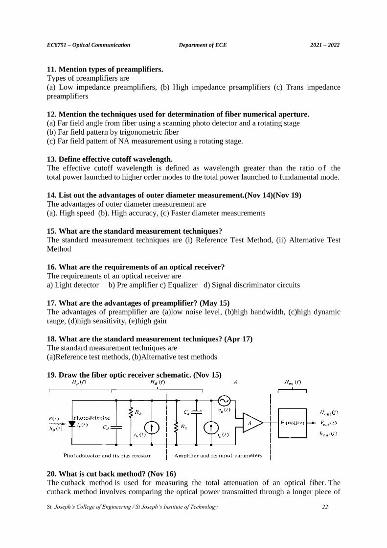
19. Draw the fiber optic receiver schematic. (Nov 15)
20. What is cut back method? (Nov 16)
The cutback method is used for measuring the total attenuation of an optical fiber. The
cutback method involves comparing the optical power transmitted through a longer piece of
EC8751 – Optical Communication Department of ECE 2021 – 2022
St. Joseph’s College of Engineering / St Joseph’s Institute of Technology 23
fiber to the power transmitted through a shorter piece of the fiber. The cutback method
requires that a test fiber of known length ‘L’ be cut back to a shorter length. It needs access
to both ends of the fiber.
21. Mention few fiber diameter measurement techniques. (Nov 15)
(i) Inner diameter measurement (ii) Outer diameter measurement
22.List out the various error sources in the receiver section. (April 19)
The various error sources in the receiver section are Quantum Noise, Bulk Dark current
Noise, Surface leakage current noise, Thermal Noise and Amplifier noise.
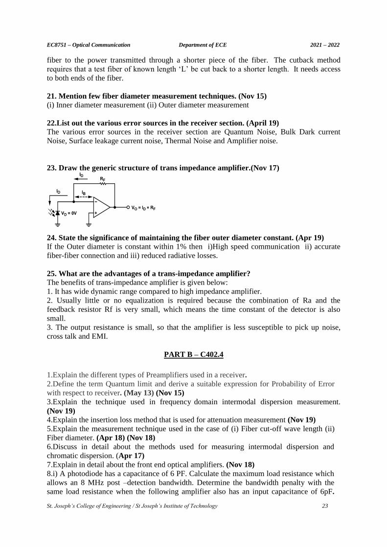
23. Draw the generic structure of trans impedance amplifier.(Nov 17)
24. State the significance of maintaining the fiber outer diameter constant. (Apr 19)
If the Outer diameter is constant within 1% then i)High speed communication ii) accurate
fiber-fiber connection and iii) reduced radiative losses.
25. What are the advantages of a trans-impedance amplifier?
The benefits of trans-impedance amplifier is given below:
1. It has wide dynamic range compared to high impedance amplifier.
2. Usually little or no equalization is required because the combination of Ra and the
feedback resistor Rf is very small, which means the time constant of the detector is also
small.
3. The output resistance is small, so that the amplifier is less susceptible to pick up noise,
cross talk and EMI.
PART B – C402.4
1.Explain the different types of Preamplifiers used in a receiver.
2.Define the term Quantum limit and derive a suitable expression for Probability of Error
with respect to receiver. (May 13) (Nov 15)
3.Explain the technique used in frequency domain intermodal dispersion measurement.
(Nov 19)
4.Explain the insertion loss method that is used for attenuation measurement (Nov 19)
5.Explain the measurement technique used in the case of (i) Fiber cut-off wave length (ii)
Fiber diameter. (Apr 18) (Nov 18)
6.Discuss in detail about the methods used for measuring intermodal dispersion and
chromatic dispersion. (Apr 17)
7.Explain in detail about the front end optical amplifiers. (Nov 18)
8.i) A photodiode has a capacitance of 6 PF. Calculate the maximum load resistance which
allows an 8 MHz post –detection bandwidth. Determine the bandwidth penalty with the
same load resistance when the following amplifier also has an input capacitance of 6pF.

EC8751 – Optical Communication Department of ECE 2021 – 2022
St. Joseph’s College of Engineering / St Joseph’s Institute of Technology 24
ii)Explain the measurement technique used in the case of Numerical aperture (Nov 17)
(Apr 19).
9. A trigonometrical measurement is performed in order to determine the numerical of a
step index fiber. The screen is positioned 10 cm from the fiber end face. When illuminated
from a wide-angled visible source the measured output pattern size 6.2 cm. Calculate the
appropriate numerical aperture of the fiber. (Apr 18)
10. Discuss the different structures of receiver in the optical fiber communication with neat
diagram. (Apr 18) (Apr 19)
11. Pulse dispersion measurements are taken over a 1.2 km length of partially graded
multimode fiber. The 3dB widths of the optical input pulses are 300 ps, and the
corresponding 3dB width for the output pulses are found to be 12.6 ns. Assuming the pulse
shapes and fiber impulses response are Gaussian, calculate: (Apr 19)
(i)The 3 dB pulses broadening for the ns km -1 (ii) The fiber bandwidth –length product.
12. Explain in brief the blocks and their functions of an optical receiver with schematic
diagram. (Apr 19)
13. (i)Discuss the various fiber Alignment losses and Joint losses with a neat sketch. (ii)
What is meant by fiber splicing? Brief in detail the techniques and methods of fiber
splicing.(Apr 19).
14. (i) Describe the various types of Connectors in detail. (ii) Explain the Lensing Schemes
used to improve optical source to fiber coupling efficiency. (Nov 19)
15. Demonstrate the following in detail : i) Optical Power Measurements ii) Attenuation
Measurements. (Nov 20)
16. Explain in detail about various lensing schemes for coupling improvement. (Nov 20)
17. An InGaAsP light source that has a refractive index of 3.540 is coupled to a step index
fiber that has a core refractive index of 1.480. Assume that the source size is smaller than the
fiber core and that there is a small gap between the source and fiber.
i) If the gap is filled with a gel that has a refractive index of 1.520, what is the power loss in
decibels from the source into fiber ?
ii) What is the power loss if no gel is used in the small gap? (Nov 20)
UNIT V- OPTICAL COMMUNICATION SYSTEMS AND NETWORKS
PART A – C402.5
1. What are solitons and give its significance? (May 13, Nov 14, May 14, May 15, Apr18)
The term “Soliton” refers to special kinds of waves that can propagate undistorted over long
distances and remain after collisions with each other. Solitons are very narrow, high-intensity
optical pulses that retain their shape through the interaction of balancing pulse dispersion
with the nonlinear properties of an optical fiber. The set of pulses that do not change in shape
are called fundamental solitons, and those that undergo periodic shape changes are called
higher-order solitons.
2. What are repeaters? In optical communications the term repeater is used to describe a piece of equipment that
receives an optical signal, converts that signal into an electrical one, regenerates it, and then
retransmits an optical signal. Since such a device converts the optical signal into an
electrical one, and then back to an optical signal, they are often known as Optical Electrical
Optical (OEO) repeaters.
EC8751 – Optical Communication Department of ECE 2021 – 2022
St. Joseph’s College of Engineering / St Joseph’s Institute of Technology 25
3. What is frequency chirping?
A chirp is a signal in which the frequency increases ('up-chirp') or decreases ('down-chirp')
with time. It is commonly used in sonar and radar, but has other applications, such as in
spread spectrum communications. In frequency chirping the rising edge of the pulse
experiences a red shift in frequency (toward higher frequencies), whereas the trailing edge of
the pulse experiences a blue shift in frequency (toward lower frequencies).
4. Why do we use NRZ coding scheme generally?
For a serial data stream, an on-off (or unipolar) signal represents the symbol 1 by a pulse of
current or light filling an entire bit period, whereas for the symbol 0 is represented by no
pulse. These codes are simple to generate and decode, but they possess no inherent error-
monitoring or correcting capabilities and they have no self-clocking (timing) features.
5. List out the benefits of SONET and PDH? (Nov 13) (May 15) Synchronous optical networking (SONET) and Synchronous Digital Hierarchy (SDH), are
multiplexing protocols that transfer multiple digital bit streams using lasers or light-
emitting diodes (LEDs) over the same optical fiber. The method was developed to replace the
Plesiochronous Digital Hierarchy (PDH) system for transporting larger amounts of telephone
calls and data traffic over the same fiber wire without synchronization problems.
6. What is Kerr effect? Nonlinearity produces a carrier induced phase modulation of the propagating signal. This is
called as Kerr effect.
7. State the concept of WDM. (Nov 14) Wavelength-division multiplexing (WDM) is a technology which multiplexes multiple
optical carrier signals on a single optical fiber by using different wavelengths (colours) of
laser light to carry different signals. This allows for a multiplication in capacity, in
addition to enabling bidirectional communications over one strand of fiber.
8. What is the significance of rise time budget? (Nov 08, Apr 08)
A rise-time budget analysis is a convenient method for determining the dispersion limitation
of an optical link. This is particularly useful for a digital link. The four basic elements that
may significantly limit optical system speed are the transmitter rise time, the group-velocity
dispersion (GVD), rise time of the fiber, the modal dispersion rise time of the fiber, and the
receiver rise time.
Where ttx - Transmitter rise time; tmod - Modal dispersion; tGVD - Rise time due to group
velocity dispersion; trx - receiver rise time
9. Compare doped fiber amplifiers and conventional repeaters. (Nov ’08)
Repeater Fiber Amplifier (i) Conversion of optical to electrical and
amplify this signal and reconvert the
electrical to optical
(ii) Used in short distance
(iii) Complex device
(iv) Bandwidth utilization is less
(i) It directly amplify the optical signal
without any conversion
(ii) Used in long distance
(iii) Device is less complex
(iv) Bandwidth is utilized effectively
EC8751 – Optical Communication Department of ECE 2021 – 2022
St. Joseph’s College of Engineering / St Joseph’s Institute of Technology 26
10. Distinguish fundamental and higher order solitons. (Nov 07,Apr 19) The family of pulses that do not change in shape are called fundamental solitons, and
those that undergo periodic shape changes are called higher-order solitons. In either case,
attenuation in the fiber will eventually decrease the soliton energy. Since this weakens the
nonlinear interaction needed to counteract group velocity dispersion, periodically spaced
optical amplifiers are required in a soliton link to restore the pulse energy.
11. What is EDFA? (May 08, May 16, Nov 18, Apr 19) An Erbium Doped Fiber Amplifier (EDFA) consists of a piece of fiber of length L, whose
core is uniformly doped with Erbium ions. Such ions can be thought of as simple two-
level systems, i.e., they can have only two energy states:1) a fundamental state and 2) an
excited state.
12. Define Modal Noise. (May 07)
Noise generated in an optical fiber system by the combination of mode-dependent optical
losses and fluctuation in the distribution of optical energy among the guided modes or in the
relative phases of the guided modes.
13. What are the system requirements in analyzing a point-to-point link?(DEC 05) The following key system requirements are needed in analyzing point-to-point link
(a). The desired (or possible) transmission distance. (b). the data or channel bandwidth
(c). the bit-error rate (BER)
14. What is DWDM? Dense Wavelength Division Multiplexing is an optical technology used to increase
bandwidth over existing fiber optic backbones. It works by combining and
transmitting multiple signals simultaneously at different wavelengths on the same fibers.
15. What are the types of broadcast and select network? a) Single hop networks b) Multi hop networks
16. Distinguish SONET and SDH. (Nov 15)
SONET SDH (i) Synchronous Optical NET work
(ii) Used in North America
(iii) Basic Signal rate:51.84Mbps
(iv) 9 Rows 90 Columns
(i) Synchronous Digital Hierarchy
(ii) Rest of the world
(iii)Basic Signal rate:155.52Mbps
(iv)9 Rows 270 Columns
17. What are the three common topologies used in fiber optic networks?(Apr 19) a) Linear Bus b) Ring c) Star
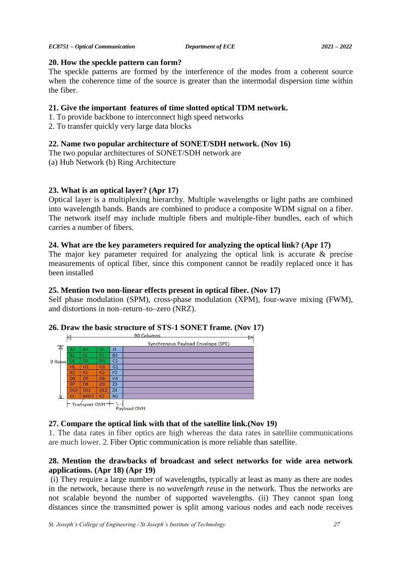
18. Define the basic signal rate of SONET. STS-1={(90 bytes/row) x (9 rows/frame) x(8 bits/byte)} / (125μs/frame) = 51.84Mbps
19. What is optical CDMA? (Nov 15) (May 16) An Optical CDMA system being a broadcast system sinks receive all source signals – as is
normal in the case of CDMA. The advantage of this scheme is that it doesn’t require any
central control.
EC8751 – Optical Communication Department of ECE 2021 – 2022
St. Joseph’s College of Engineering / St Joseph’s Institute of Technology 27
20. How the speckle pattern can form? The speckle patterns are formed by the interference of the modes from a coherent source
when the coherence time of the source is greater than the intermodal dispersion time within
the fiber.
21. Give the important features of time slotted optical TDM network. 1. To provide backbone to interconnect high speed networks
2. To transfer quickly very large data blocks
22. Name two popular architecture of SONET/SDH network. (Nov 16)
The two popular architectures of SONET/SDH network are
(a) Hub Network (b) Ring Architecture
23. What is an optical layer? (Apr 17)
Optical layer is a multiplexing hierarchy. Multiple wavelengths or light paths are combined
into wavelength bands. Bands are combined to produce a composite WDM signal on a fiber.
The network itself may include multiple fibers and multiple-fiber bundles, each of which
carries a number of fibers.
24. What are the key parameters required for analyzing the optical link? (Apr 17)
The major key parameter required for analyzing the optical link is accurate & precise
measurements of optical fiber, since this component cannot be readily replaced once it has
been installed
25. Mention two non-linear effects present in optical fiber. (Nov 17)
Self phase modulation (SPM), cross-phase modulation (XPM), four-wave mixing (FWM),
and distortions in non–return–to–zero (NRZ).
26. Draw the basic structure of STS-1 SONET frame. (Nov 17)
27. Compare the optical link with that of the satellite link.(Nov 19)
1. The data rates in fiber optics are high whereas the data rates in satellite communications
are much lower. 2. Fiber Optic communication is more reliable than satellite.
28. Mention the drawbacks of broadcast and select networks for wide area network
applications. (Apr 18) (Apr 19)
(i) They require a large number of wavelengths, typically at least as many as there are nodes
in the network, because there is no wavelength reuse in the network. Thus the networks are
not scalable beyond the number of supported wavelengths. (ii) They cannot span long
distances since the transmitted power is split among various nodes and each node receives
EC8751 – Optical Communication Department of ECE 2021 – 2022
St. Joseph’s College of Engineering / St Joseph’s Institute of Technology 28
only a small fraction of the transmitted power, which becomes smaller as the number of
nodes increases.
29. Define power penalty. (Nov 18) (Nov 19) (Nov 20)
The signal power has to be increased to achieve the same SNR or BER performance as that of
an ideal system to compensate for the system degradation. This increase in power is called
the Power Penalty.
30. Consider a spectral band of 0.8 nm (or equivalently, a mean frequency spacing of
100 GHz at a 1550 nm wavelength) within which lasers with narrow linewidths are
transmitting. How many of such signal channels fit into the C band? (Nov 20) Because the C-band ranges from 1530 to 1565 nm, one can have N = (35 nm) / (0.8 nm per
channel) = 43 independent signal channels.
PART B - C402.5
1.Explain the SONET frame structures and SONET rings with neat diagrams. (Nov18, Apr
19, Nov 20)
2.Explain the principles of WDM Networks. (Nov 18, Apr 19)
3.Describe Non-linear optical effects in detail. (May 15, Nov 18, Apr 18, Apr 19)
4.Write notes on Solitons. (Nov 13, Apr 19)
5.Explain the following requirements for the design of an optically amplified WDM link: (i)
Link Band width (ii)Optical power requirements for a specific BER
6.Explain with neat sketch of two popular architecture of SONET. (May 16)
7.Explain in detail different types of Broad cast-and – select WDM networks. (May 16)
8.Write a note on optical switching methods. (Nov 17).
9.What is optical power budgeting? Determine the optical power budget for the below system
and hence determine its viability. Components are chosen for a digital optical fiber link of
overall length 7 Km and operating at 20 Mbits per sec using RZ code. It is decided that an
LED emitting at 0.85 µm with graded index fiber to a pin photodiode is a suitable choice for
the system components giving no dispersion equalization penalty. An LED which is capable
of launching an average of 100 µW of optical power (including connected loss) into a graded
index fiber of 50 µm core diameter is chosen. The proposed fiber cable has an attenuation of
2.6 dB km-1 and requires splicing every kilometer with a loss of 0.5 dB per splice. There is
also a connecter loss at the receiver of 1.5 dB. The receiver mean incident optical power of -
41 dBm in order to give the necessary BER of 10-10 , and it is predicted that a safety margin
of 6 dB will be required. (Apr 18)
10.Discuss about the concept of routing and wavelength assignment technique in the
wavelength routed networks. (Apr 18)
11.Briefly explain the layers of SONET. (Apr 18)
12.(i)Analyze the rise time budget for a fiber link. (ii) Assume that LED together with drive
circuit has a rise time of 15 ns. LED has spectral width of 40nm. We have a material
dispersion related rise time degradation of 21 ns over the 6km link. The rise time degradation
from the receiver is 14 ns. The modal dispersion induced fiber rise time is 3.9ns.calculate link
rise time. (Nov 19)
13.With suitable example, explain the condition and constrains in the formulation and finding
solution for routing and wavelength assignment problem in a optimal way. (Nov 19).
14. Explain about Link power budget and rise time budget. (Nov 20)