Embed Size (px)
Citation preview
andandandandandInstallaInstallaInstallaInstallaInstallationtiontiontiontion
TWINTWINTWINTWINTWIN DISCDISCDISCDISCDISCINCORPORAINCORPORAINCORPORAINCORPORAINCORPORATEDTEDTEDTEDTED
MarineMarineMarineMarineMarineContrContrContrContrControl Systemol Systemol Systemol Systemol System
Model:EC300
Document Number: 1020607
OperOperOperOperOperaaaaator’tor’tor’tor’tor’sssssManualManualManualManualManual

NOTICE
Twin Disc, Incorporated makes no warranty or guaranty of anykind, expressed, implied or otherwise, with regard to theinformation contained within this manual. Twin Disc, Incorporatedhas developed this manual through research and testing of theinformation contained therein. Twin Disc, Incorporated assumesno responsibility for any errors that may appear in this manualand shall not be liable under any circumstances for incidental,consequential or punitive damages in connection with, or arisingout of, the use of this manual. The information contained withinthis manual is subject to change without notice.
Document Number1020607
September 2003
Marine Control SystemInstallation and
Operator’s Manual

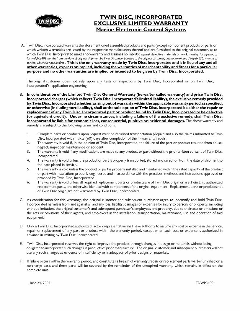
TWIN DISC, INCORPORATED EXCLUSIVE LIMITED WARRANTY Marine Electronic Control Systems
A. Twin Disc, Incorporated warrants the aforementioned assembled products and parts (except component products or parts on
which written warranties are issued by the respective manufacturers thereof and are furnished to the original customer, as to which Twin Disc, Incorporated makes no warranty and assumes no liability) against defective materials or workmanship for a period of forty-eight (48) months from the date of original shipment by Twin Disc, Incorporated to the original customer, but not to exceed thirty-six (36) months of service, whichever occurs first . This is the only warranty made by Twin Disc, Incorporated and is in lieu of any and all other warranties, express or implied, including the warranties of merchantability and fitness for a particular purpose and no other warranties are implied or intended to be given by Twin Disc, Incorporated.
The original customer does not rely upon any tests or inspections by Twin Disc, Incorporated or on Twin Disc, Incorporated’s application engineering.
B. In consideration of the Limited Twin Disc General Warranty (hereafter called warranty) and price Twin Disc,
Incorporated charges (which reflects Twin Disc, Incorporated’s limited liability), the exclusive remedy provided by Twin Disc, Incorporated whether arising out of warranty within the applicable warranty period as specified, or otherwise (including tort liability), shall at the sole option of Twin Disc, Incorporated be either the repair or replacement of any Twin Disc, Incorporated part or product found by Twin Disc, Incorporated to be defective (or equivalent credit). Under no circumstances, including a failure of the exclusive remedy, shall Twin Disc, Incorporated be liable for economic loss, consequential, punitive or incidental damages. The above warranty and remedy are subject to the following terms and conditions:
1. Complete parts or products upon request must be returned transportation prepaid and also the claims submitted to Twin
Disc, Incorporated within sixty (60) days after completion of the in-warranty repair. 2. The warranty is void if, in the opinion of Twin Disc, Incorporated, the failure of the part or product resulted from abuse,
neglect, improper maintenance or accident. 3. The warranty is void if any modifications are made to any product or part without the prior written consent of Twin Disc,
Incorporated. 4. The warranty is void unless the product or part is properly transported, stored and cared for from the date of shipment to
the date placed in service. 5. The warranty is void unless the product or part is properly installed and maintained within the rated capacity of the product
or part with installations properly engineered and in accordance with the practices, methods and instructions approved or provided by Twin Disc, Incorporated.
6. The warranty is void unless all required replacement parts or products are of Twin Disc origin or are Twin Disc authorized replacement parts, and otherwise identical with components of the original equipment. Replacement parts or products not of Twin Disc origin are not warranted by Twin Disc, Incorporated.
C. As consideration for this warranty, the original customer and subsequent purchaser agree to indemnify and hold Twin Disc,
Incorporated harmless from and against all and any loss, liability, damages or expenses for injury to persons or property, including without limitation, the original customer’s and subsequent purchaser’s employees and property, due to their acts or omissions or the acts or omissions of their agents, and employees in the installation, transportation, maintenance, use and operation of said equipment.
D. Only a Twin Disc, Incorporated authorized factory representative shall have authority to assume any cost or expense in the service,
repair or replacement of any part or product within the warranty period, except when such cost or expense is authorized in advance in writing by Twin Disc, Incorporated.
E. Twin Disc, Incorporated reserves the right to improve the product through changes in design or materials without being
obligated to incorporate such changes in products of prior manufacture. The original customer and subsequent purchasers will not use any such changes as evidence of insufficiency or inadequacy of prior designs or materials.
F. If failure occurs within the warranty period, and constitutes a breach of warranty, repair or replacement parts will be furnished on a
no-charge basis and these parts will be covered by the remainder of the unexpired warranty which remains in effect on the complete unit.
June 24, 2003 TDWP3100


7
Twin Disc, Incorporated Table of Contents
EC300 Marine Control System Installation Manual #1020607
Table of ContentsIntroduction ................................................................... 11
Preface .................................................................................................................... 11General Information ............................................................................................... 13Replacement Parts................................................................................................. 14Safety ...................................................................................................................... 15Source of Service Information .............................................................................. 15Sectional Contents ................................................................................................ 16Required Tools ....................................................................................................... 17Required Supplies ................................................................................................. 18Additional Materials ............................................................................................... 21Other Items Which May Be Required .................................................................... 21
Component Installation ................................................ 27General Installation Guidelines ............................................................................. 27EC300 Control Installation .................................................................................... 30Control Head Installation ....................................................................................... 31Control Head Lever Drag Adjustment .................................................................. 37Station Doubler Installation ................................................................................... 39Engine Speed Sensor Installation ........................................................................ 40Servo Actuator Installation .................................................................................... 44Push-Pull Cable Installation .................................................................................. 46Twin Disc Display Installation ............................................................................... 58Lever Function Switch Installation ....................................................................... 60
Electrical Installation .................................................... 61Introduction ............................................................................................................ 61Control Head Harness (J1, J2, or J3) Installation ................................................ 71Service Connector (J4) .......................................................................................... 86Engine Control Harness (J5) Installation ............................................................. 86Engine Room Analog Harness (J6) Installation ................................................... 99PWM Drivers Harness (J7) Installation ............................................................... 102Miscellaneous Bridge Signals Harness (J8) Installation................................... 105Twin Disc Display Harness (J9) Installation ....................................................... 112Communication Harness (J10) Installation ........................................................ 115Servo Actuator Harness (J11) Installation .......................................................... 119Engine Room Switch Harness (J12) Installation ............................................... 121EC300 Control Power and Grounding Harness (J13) Installation.................... 124
8
Twin Disc, IncorporatedTable of Contents
EC300 Marine Control System Installation Manual #1020607
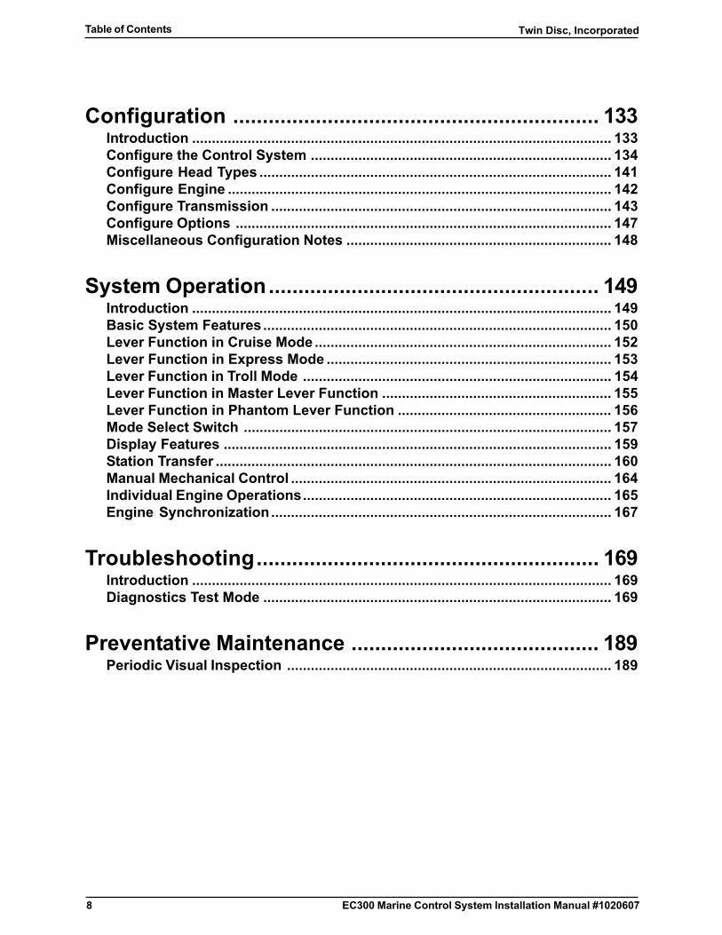
Configuration .............................................................. 133Introduction .......................................................................................................... 133Configure the Control System ............................................................................ 134Configure Head Types ......................................................................................... 141Configure Engine ................................................................................................. 142Configure Transmission ...................................................................................... 143Configure Options ............................................................................................... 147Miscellaneous Configuration Notes ................................................................... 148
System Operation........................................................ 149Introduction .......................................................................................................... 149Basic System Features........................................................................................ 150Lever Function in Cruise Mode ........................................................................... 152Lever Function in Express Mode ........................................................................ 153Lever Function in Troll Mode .............................................................................. 154Lever Function in Master Lever Function .......................................................... 155Lever Function in Phantom Lever Function ...................................................... 156Mode Select Switch ............................................................................................. 157Display Features .................................................................................................. 159Station Transfer .................................................................................................... 160Manual Mechanical Control ................................................................................. 164Individual Engine Operations.............................................................................. 165Engine Synchronization...................................................................................... 167
Troubleshooting.......................................................... 169Introduction .......................................................................................................... 169Diagnostics Test Mode ........................................................................................ 169
Preventative Maintenance .......................................... 189Periodic Visual Inspection .................................................................................. 189

9
Twin Disc, Incorporated Table of Contents
EC300 Marine Control System Installation Manual #1020607
Engineering Drawings ................................................ 191List of Engineering Drawings ............................................................................. 191Morse 33 Series Cable Mounting Dimensions ................................................... 193EC300 Control Mounting Dimensions Sheet 1 (1020676) ................................. 194EC300 Control Mounting Dimensions Sheet 2 (1020676) ................................. 195Servo Actuator Mounting Dimensions ............................................................... 196Twin Disc Display Mounting Dimensions (1018791) ......................................... 197Control Head Mounting Template ....................................................................... 207Interface Assembly Mounting Template ............................................................. 209Selector Assembly Mounting Template .............................................................. 211
Appendix ...................................................................... A-1

10
Twin Disc, IncorporatedTable of Contents
EC300 Marine Control System Installation Manual #1020607
This page intentionally blank
11
Twin Disc, Incorporated Introduction
EC300 Marine Control System Installation Manual #1020607
Introduction
Preface
The Twin Disc Incorporated product line of electronic Marine Control Systemsprovides remote operation of engine throttle and transmission engagement.The model EC300 Marine Control System is designed for use with currentElectronic Throttle and/or Electric Shift propulsion systems used within thepleasure and work-boat markets. The EC300 Control has many specialfeatures which provide flexibility and adaptability for use with the vast majorityof engine/transmission combinations including popular options such as EngineSync, Trolling, Shaft Brake, Mechanical Actuator Output, Transmission OilPressure and Oil Temperature Monitoring, Master and Phantom lever function,Alarm Output, and Helm Display.
The following installation instructions provide the necessary information onComponent Installation, Electrical Installation, Configuration, SystemOperation and Troubleshooting. Review the entire manual for the optionsspecific to your application, and become familiar with all Customer Suppliedmaterials and tools that may be required. In addition, while the manual isoutlined for the general sequence of installation from setup throughtroubleshooting, a good understanding of all aspects of the installation willhelp make for a smoother installation process.
For most applications, the installation process is as follows:
1. Read and understand this manual. Contact the supplier of the system,your local Twin Disc Distributor, or the Twin Disc Inc. website for help:http://www.twindisc.com
2. Locate desired positions for Control Heads, Controls and generalrouting of interconnecting harnessing.
3. Identify locations for vessel interconnections such as Ignition, PowerWiring, Electronic Throttle, Electric Shift, Speed Sensing etc. Engineand transmission installation manuals and vessel wiring diagrams maybe needed for reference.
4. Purchase/fabricate any necessary “Customer Supplied” items or tools.
5. Finalize locations of Control Heads and Controls.

12
Twin Disc, IncorporatedIntroduction
EC300 Marine Control System Installation Manual #1020607
6. Install harnessing and wiring.
7. Inspect the installation against the manual. Document componentpart and serial numbers and any particulars regarding wire colorsand locations specific to the application.
8. Process initial tests, adjustments and troubleshooting.
9. Process final test/sea-trial.
13
Twin Disc, Incorporated Introduction
EC300 Marine Control System Installation Manual #1020607
General Information
This publication provides the information necessary for the installation ofthe Twin Disc Model EC300 Control System.
This manual is designed to facilitate the installation of the EC300 ControlSystem by the customer. The installer should perform the work as presented inthis manual. Twin Disc, Incorporated and its local distributors are available toassist in the installation.
The components as supplied with the order meet the codes and standardsthat were applicable when the order was placed. This instruction manual isprepared to address many of the applicable requirements of the followingthat are effective on the date that this manual is prepared:
❑ American Boat & Yacht Council (ABYC) Direct Current (DC) ElectricalSystems on Boats Standard E-9.
❑ American Bureau of Shipping’s (ABS) Rules for Building and ClassingSteel Vessels 2002.
❑ American Bureau of Shipping’s (ABS) Rules for Building and ClassingSteel Vessels Under 90 Meters (295 Feet) 2001.
However, the customer is responsible for meeting all currently applicablecode and standard requirements for the component installation at the timeof installation.
The following instructions cover typical installation of single- or twin-enginesystems with one, two, or three control stations as standard equipment.However, these instructions also cover installation of up to eight enginesystems with optional accessories and cables.
The EC300 Control System is supplied in response to specific orders forspecific applications. Based upon the details of the order, certain featuresand options that are described in this manual will not be applicable. Forspecific component information, refer to the system installation drawingsupplied for your application.
14
Twin Disc, IncorporatedIntroduction
EC300 Marine Control System Installation Manual #1020607
Replacement Parts
Parts List
Engineering assembly drawings are provided in appropriate sections of thismanual to facilitate ordering spare or replacement parts. Current systemdrawings are available from Twin Disc Inc. or the nearest authorized Twin DiscInc. Distributor.
Ordering Parts
WARNINGAll replacement parts or products must be of Twin Disc Inc. origin orequal, and otherwise identical with components of the originalequipment. Use of any other parts or products will void the warrantyand may result in malfunction or accident, causing injury to personneland/or serious damage to the equipment.
Renewal parts and service parts kits may be obtained from any authorizedTwin Disc Inc. distributor or service dealer.
Twin Disc Incorporated, having stipulated the part number on the unit’snameplate, absolves itself of any responsibility resulting from any external,internal or installation changes made in the field without the express writtenapproval of Twin Disc Inc.
15
Twin Disc, Incorporated Introduction
EC300 Marine Control System Installation Manual #1020607
Safety
All people installing and operating this unit must employ safe operatingpractices. Twin Disc Incorporated is not responsible for any personal injuryresulting from any unsafe and careless use of hand tools, power tools, liftingequipment, or from any unsafe practices during installation and operation.
Because of the possible danger to people or property from accidents thatmay result from the use of manufactured products, it is important that correctprocedures be followed. Products must be used in accordance with theinformation specified.
Proper installation procedures must be used. Proper safety devices, suchas guards, may be required as specified in applicable codes. Safety devicesare not provided by Twin Disc Incorporated nor are they the responsibility ofTwin Disc Incorporated.
Source of Service Information
This manual is current at the time of printing. Changes are made to themanual for advances in technology and improvement in the state of the artwhen required. All revisions and design improvements are subject to changewithout notice.
Individual product service bulletins are issued to provide Twin Disc distributorswith immediate notice of new service information. These service bulletinsare distributed to all Twin Disc EC300 Control distributors throughout theUnited States and many foreign countries.
For the latest service information on Twin Disc Inc. products, contact anyTwin Disc distributor or service dealer. This can be done on the Twin Disccorporate web site found at [http://www.twindisc.com]. Provide your systemdrawing number. If necessary, contact the Product Service Department,Twin Disc Incorporated, Racine, Wisconsin 53405-3698, USA by e-mail [email protected].
16
Twin Disc, IncorporatedIntroduction
EC300 Marine Control System Installation Manual #1020607
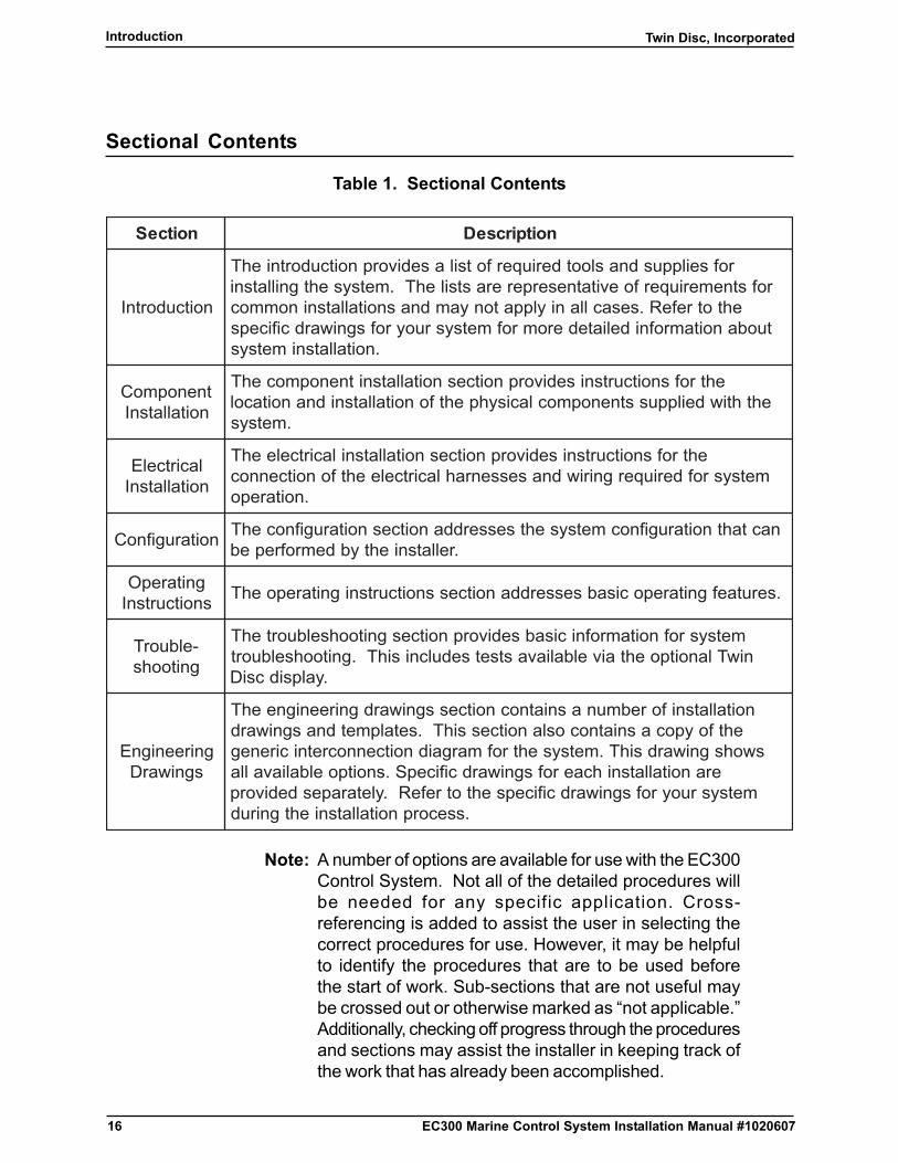
Sectional Contents
Table 1. Sectional Contents
noitceS noitpircseD
noitcudortnI
rofseilppusdnaslootderiuqerfotsilasedivorpnoitcudortniehTrofstnemeriuqerfoevitatneserpererastsilehT.metsysehtgnillatsni
ehtotrefeR.sesacllaniylppatonyamdnasnoitallatsninommoctuobanoitamrofnideliatederomrofmetsysruoyrofsgniwardcificeps
.noitallatsnimetsys
tnenopmoCnoitallatsnI
ehtrofsnoitcurtsnisedivorpnoitcesnoitallatsnitnenopmocehTehthtiwdeilppusstnenopmoclacisyhpehtfonoitallatsnidnanoitacol
.metsys
lacirtcelEnoitallatsnI
ehtrofsnoitcurtsnisedivorpnoitcesnoitallatsnilacirtceleehTmetsysrofderiuqergniriwdnasessenrahlacirtceleehtfonoitcennoc
.noitarepo
noitarugifnoC nactahtnoitarugifnocmetsysehtsesserddanoitcesnoitarugifnocehT.rellatsniehtybdemrofrepeb
gnitarepOsnoitcurtsnI .serutaefgnitarepocisabsesserddanoitcessnoitcurtsnignitarepoehT
-elbuorTgnitoohs
metsysrofnoitamrofnicisabsedivorpnoitcesgnitoohselbuortehTniwTlanoitpoehtaivelbaliavastsetsedulcnisihT.gnitoohselbuort
.yalpsidcsiD
gnireenignEsgniwarD
noitallatsniforebmunasniatnocnoitcessgniwardgnireenigneehTehtfoypocasniatnocoslanoitcessihT.setalpmetdnasgniward
swohsgniwardsihT.metsysehtrofmargaidnoitcennocretnicirenegeranoitallatsnihcaerofsgniwardcificepS.snoitpoelbaliavalla
metsysruoyrofsgniwardcificepsehtotrefeR.yletarapesdedivorp.ssecorpnoitallatsniehtgnirud
Note: A number of options are available for use with the EC300Control System. Not all of the detailed procedures willbe needed for any specific application. Cross-referencing is added to assist the user in selecting thecorrect procedures for use. However, it may be helpfulto identify the procedures that are to be used beforethe start of work. Sub-sections that are not useful maybe crossed out or otherwise marked as “not applicable.”Additionally, checking off progress through the proceduresand sections may assist the installer in keeping track ofthe work that has already been accomplished.

17
Twin Disc, Incorporated Introduction
EC300 Marine Control System Installation Manual #1020607
Note: Dimensions provided in this manual are in mm (in) unlessotherwise specified.
Required Tools
Note: Not all installations will require all of the tools itemizedbelow. All of the tools would be required for the mostcomplex installation.
Installation may require the following tools:
� Electric or pneumatic drill
� Assorted drill bits
� Center punch
� #1 Phillips screwdriver
� Screwdriver with a 1/8 in. blade
� Wire terminal crimpers
� Wire strippers
� DC voltmeter or multimeter
� Watch with a seconds hand
� Tachometer, oscilloscope, or frequency counter for troubleshooting dualengine applications
� 3/32 in. hex key (Allen) wrench
� 1/8 in. hex key (Allen) wrench
� Deutsch crimp tool (P/N HDT 48-00) for 12 to 24 AWG wire sizes
� Torque wrench capable of measuring 4.52 Nm (40 in-lb) for installing aspeed sensor in the flywheel housing and for mounting components
� File, rasp, or sandpaper to smooth cut surfaces
� 500 VDC Megohmmeter for testing power wiring as per ABSrequirements.
18
Twin Disc, IncorporatedIntroduction
EC300 Marine Control System Installation Manual #1020607
Required Supplies
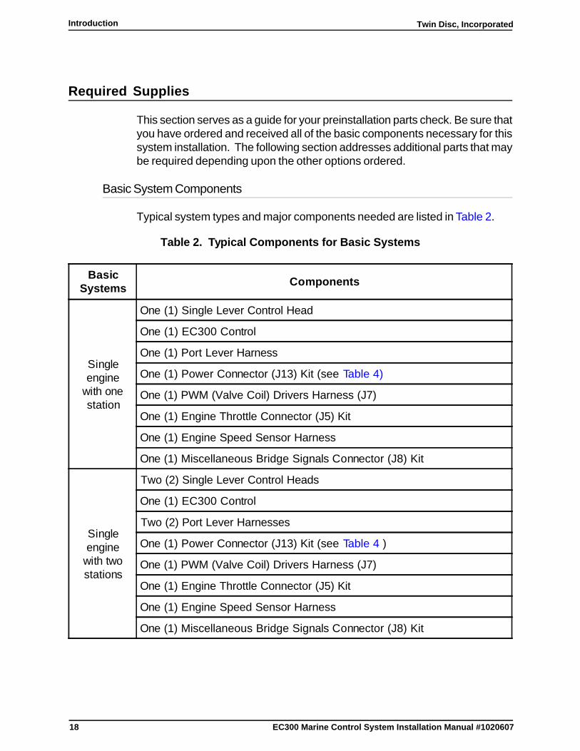
This section serves as a guide for your preinstallation parts check. Be sure thatyou have ordered and received all of the basic components necessary for thissystem installation. The following section addresses additional parts that maybe required depending upon the other options ordered.
Basic System Components
Typical system types and major components needed are listed in Table 2.
Table 2. Typical Components for Basic Systems
BasicSystems Components
Singleengine
with onestation
One (1) Single Lever Control Head
One (1) EC300 Control
One (1) Port Lever Harness
One (1) Power Connector (J13) Kit (see Table 4)
One (1) PWM (Valve Coil) Drivers Harness (J7)
One (1) Engine Throttle Connector (J5) Kit
One (1) Engine Speed Sensor Harness
One (1) Miscellaneous Bridge Signals Connector (J8) Kit
Singleengine
with twostations
Two (2) Single Lever Control Heads
One (1) EC300 Control
Two (2) Port Lever Harnesses
One (1) Power Connector (J13) Kit (see Table 4 )
One (1) PWM (Valve Coil) Drivers Harness (J7)
One (1) Engine Throttle Connector (J5) Kit
One (1) Engine Speed Sensor Harness
One (1) Miscellaneous Bridge Signals Connector (J8) Kit
19
Twin Disc, Incorporated Introduction
EC300 Marine Control System Installation Manual #1020607
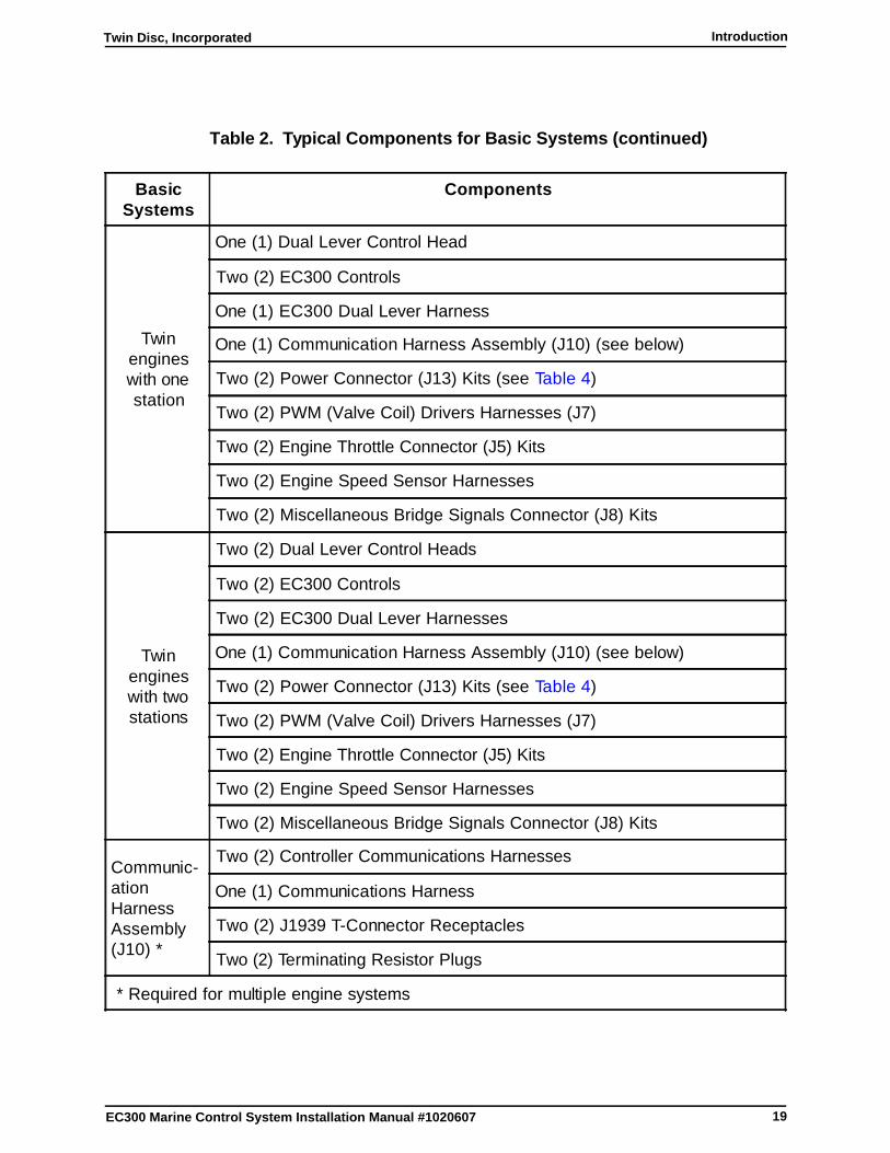
Table 2. Typical Components for Basic Systems (continued)
BasicSystems
Components
Twinengineswith onestation
One (1) Dual Lever Control Head
Two (2) EC300 Controls
One (1) EC300 Dual Lever Harness
One (1) Communication Harness Assembly (J10) (see below)
Two (2) Power Connector (J13) Kits (see Table 4)
Two (2) PWM (Valve Coil) Drivers Harnesses (J7)
Two (2) Engine Throttle Connector (J5) Kits
Two (2) Engine Speed Sensor Harnesses
Two (2) Miscellaneous Bridge Signals Connector (J8) Kits
Twinengineswith twostations
Two (2) Dual Lever Control Heads
Two (2) EC300 Controls
Two (2) EC300 Dual Lever Harnesses
One (1) Communication Harness Assembly (J10) (see below)
Two (2) Power Connector (J13) Kits (see Table 4)
Two (2) PWM (Valve Coil) Drivers Harnesses (J7)
Two (2) Engine Throttle Connector (J5) Kits
Two (2) Engine Speed Sensor Harnesses
Two (2) Miscellaneous Bridge Signals Connector (J8) Kits
Communic-ationHarnessAssembly(J10) *
Two (2) Controller Communications Harnesses
One (1) Communications Harness
Two (2) J1939 T-Connector Receptacles
Two (2) Terminating Resistor Plugs
* Required for multiple engine systems
20
Twin Disc, IncorporatedIntroduction
EC300 Marine Control System Installation Manual #1020607
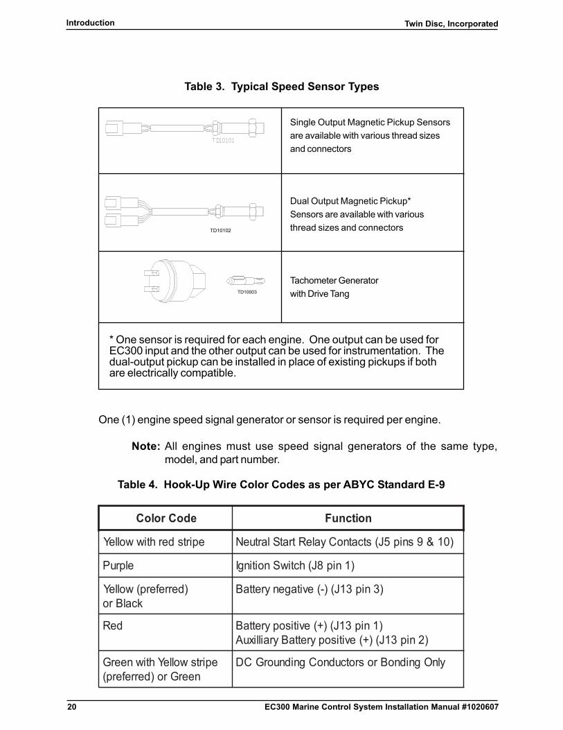
Table 3. Typical Speed Sensor Types
One (1) engine speed signal generator or sensor is required per engine.
Note: All engines must use speed signal generators of the same type,model, and part number.
Table 4. Hook-Up Wire Color Codes as per ABYC Standard E-9
edoCroloC noitcnuF
epirtsderhtiwwolleY )01&9snip5J(stcatnoCyaleRtratSlartueN
elpruP )1nip8J(hctiwSnoitingI
)derreferp(wolleYkcalBro
)3nip31J()-(evitagenyrettaB
deR )1nip31J()+(evitisopyrettaB)2nip31J()+(evitisopyrettaByraillixuA
epirtswolleYhtiwneerGneerGro)derreferp(
ylnOgnidnoBrosrotcudnoCgnidnuorGCD
Single Output Magnetic Pickup Sensorsare available with various thread sizesand connectors
TD10102
Dual Output Magnetic Pickup*Sensors are available with variousthread sizes and connectors
TD10003
Tachometer Generatorwith Drive Tang
* One sensor is required for each engine. One output can be used forEC300 input and the other output can be used for instrumentation. Thedual-output pickup can be installed in place of existing pickups if bothare electrically compatible.
21
Twin Disc, Incorporated Introduction
EC300 Marine Control System Installation Manual #1020607
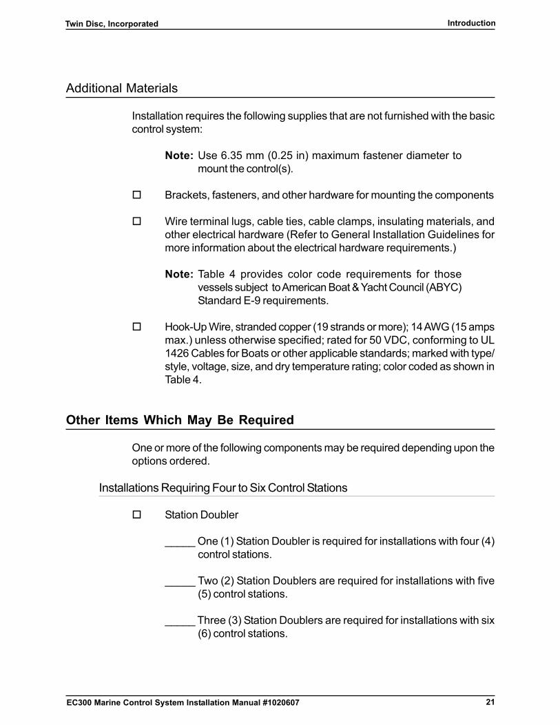
Additional Materials
Installation requires the following supplies that are not furnished with the basiccontrol system:
Note: Use 6.35 mm (0.25 in) maximum fastener diameter tomount the control(s).
� Brackets, fasteners, and other hardware for mounting the components
� Wire terminal lugs, cable ties, cable clamps, insulating materials, andother electrical hardware (Refer to General Installation Guidelines formore information about the electrical hardware requirements.)
Note: Table 4 provides color code requirements for thosevessels subject to American Boat & Yacht Council (ABYC)Standard E-9 requirements.
� Hook-Up Wire, stranded copper (19 strands or more); 14 AWG (15 ampsmax.) unless otherwise specified; rated for 50 VDC, conforming to UL1426 Cables for Boats or other applicable standards; marked with type/style, voltage, size, and dry temperature rating; color coded as shown inTable 4.
Other Items Which May Be Required
One or more of the following components may be required depending upon theoptions ordered.
Installations Requiring Four to Six Control Stations
� Station Doubler
_____ One (1) Station Doubler is required for installations with four (4)control stations.
_____ Two (2) Station Doublers are required for installations with five(5) control stations.
_____ Three (3) Station Doublers are required for installations with six(6) control stations.
22
Twin Disc, IncorporatedIntroduction
EC300 Marine Control System Installation Manual #1020607
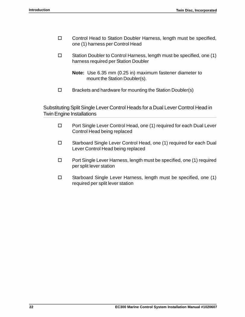
� Control Head to Station Doubler Harness, length must be specified,one (1) harness per Control Head
� Station Doubler to Control Harness, length must be specified, one (1)harness required per Station Doubler
Note: Use 6.35 mm (0.25 in) maximum fastener diameter tomount the Station Doubler(s).
� Brackets and hardware for mounting the Station Doubler(s)
Substituting Split Single Lever Control Heads for a Dual Lever Control Head inTwin Engine Installations
� Port Single Lever Control Head, one (1) required for each Dual LeverControl Head being replaced
� Starboard Single Lever Control Head, one (1) required for each DualLever Control Head being replaced
� Port Single Lever Harness, length must be specified, one (1) requiredper split lever station
� Starboard Single Lever Harness, length must be specified, one (1)required per split lever station
23
Twin Disc, Incorporated Introduction
EC300 Marine Control System Installation Manual #1020607
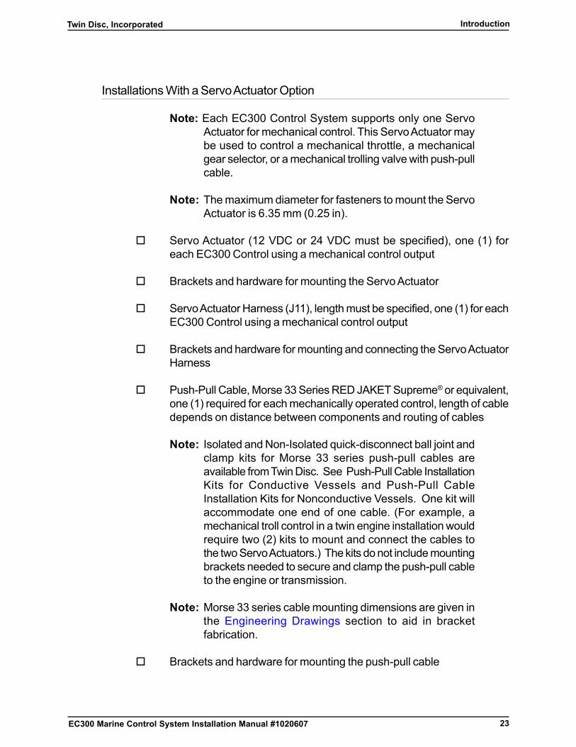
Installations With a Servo Actuator Option
Note: Each EC300 Control System supports only one ServoActuator for mechanical control. This Servo Actuator maybe used to control a mechanical throttle, a mechanicalgear selector, or a mechanical trolling valve with push-pullcable.
Note: The maximum diameter for fasteners to mount the ServoActuator is 6.35 mm (0.25 in).
� Servo Actuator (12 VDC or 24 VDC must be specified), one (1) foreach EC300 Control using a mechanical control output
� Brackets and hardware for mounting the Servo Actuator
� Servo Actuator Harness (J11), length must be specified, one (1) for eachEC300 Control using a mechanical control output
� Brackets and hardware for mounting and connecting the Servo ActuatorHarness
� Push-Pull Cable, Morse 33 Series RED JAKET Supreme® or equivalent,one (1) required for each mechanically operated control, length of cabledepends on distance between components and routing of cables
Note: Isolated and Non-Isolated quick-disconnect ball joint andclamp kits for Morse 33 series push-pull cables areavailable from Twin Disc. See Push-Pull Cable InstallationKits for Conductive Vessels and Push-Pull CableInstallation Kits for Nonconductive Vessels. One kit willaccommodate one end of one cable. (For example, amechanical troll control in a twin engine installation wouldrequire two (2) kits to mount and connect the cables tothe two Servo Actuators.) The kits do not include mountingbrackets needed to secure and clamp the push-pull cableto the engine or transmission.
Note: Morse 33 series cable mounting dimensions are given inthe Engineering Drawings section to aid in bracketfabrication.
� Brackets and hardware for mounting the push-pull cable

24
Twin Disc, IncorporatedIntroduction
EC300 Marine Control System Installation Manual #1020607
Installation In Starter Solenoid Circuits Greater Than 5 Amps
� Relay, Normally Open (NO) Single Pole Single Throw (SPST), coilvoltage rating equal to the starter solenoid voltage, contact current ratinggreater than the starter solenoid current, one (1) required per control,customer supplied
Push-Pull Cable Installation on Nonconductive Vessels
� Insulated push-pull cable mounting hardware may be necessary to satisfybonding or isolation requirements, especially if the engine block is notgrounded. Single and Dual Nylon Installation Kits are available. ConsultTwin Disc Incorporated or a local distributor for further information or toorder insulated push-pull cable mounting hardware
Master or Phantom Switch Installations
Note: Switches and controls must be marked to indicate theusage. Most switch manufacturers provide legend platesfor their switches.
� Toggle switch, DC Current rating greater than 0.5 amps, one (1) requiredif either switch is used
25
Twin Disc, Incorporated Introduction
EC300 Marine Control System Installation Manual #1020607
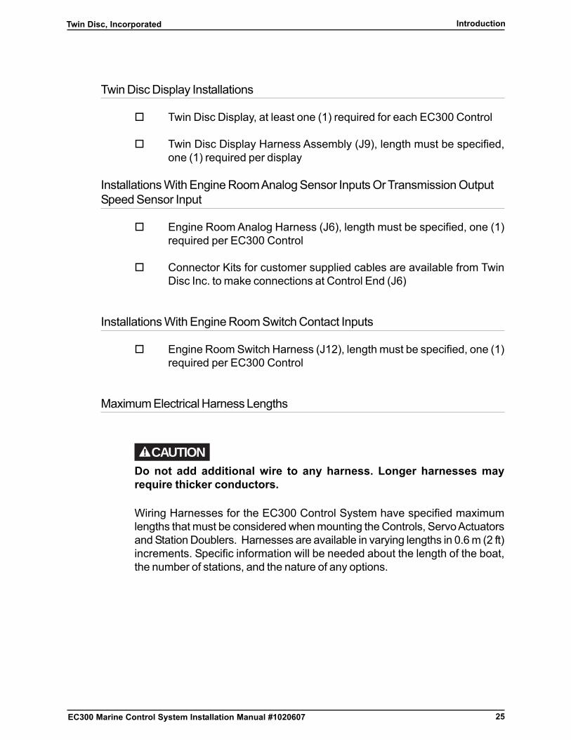
Twin Disc Display Installations
� Twin Disc Display, at least one (1) required for each EC300 Control
� Twin Disc Display Harness Assembly (J9), length must be specified,one (1) required per display
Installations With Engine Room Analog Sensor Inputs Or Transmission OutputSpeed Sensor Input
� Engine Room Analog Harness (J6), length must be specified, one (1)required per EC300 Control
� Connector Kits for customer supplied cables are available from TwinDisc Inc. to make connections at Control End (J6)
Installations With Engine Room Switch Contact Inputs
� Engine Room Switch Harness (J12), length must be specified, one (1)required per EC300 Control
Maximum Electrical Harness Lengths
CAUTIONDo not add additional wire to any harness. Longer harnesses mayrequire thicker conductors.
Wiring Harnesses for the EC300 Control System have specified maximumlengths that must be considered when mounting the Controls, Servo Actuatorsand Station Doublers. Harnesses are available in varying lengths in 0.6 m (2 ft)increments. Specific information will be needed about the length of the boat,the number of stations, and the nature of any options.

26
Twin Disc, IncorporatedIntroduction
EC300 Marine Control System Installation Manual #1020607
This page intentionally blank
27
Twin Disc, Incorporated Component Installation
EC300 Marine Control System Installation Manual #1020607
Component Installation
General Installation Guidelines
EC300 Control Systems should be mounted near the engines in a locationreasonably free from direct splash and spray, and protected from mechanicalabuse. When selecting the location for mounting the components, considerationshould be given to any push-pull cable routing in order to avoid sharp bends orexcessive lengths. The mounting surface should be flat, or shimmed so that thecontrol enclosure is secured without distortion to the bottom plate. Controlsshould not be mounted on the engines unless they are protected by a heatshield and mounted to a vibration-damped plate.
Ensure a suitable location is chosen for mounting the EC300 Control(s), ControlHead(s), Twin Disc Display(s), and any other components. Choose a locationthat meets the following criteria:
� It is not on any drivetrain component.
� It is away from heat sources.
� It is clear of service and access areas.
� It is away from AC power and high current conductors.
� It is protected from submersion or splash.
� It will not provide a “step” for personnel.
� It is a minimum of 1 m (3.3 ft) away from alternators, generators,communications equipment, and associated leads.
� It is away from high vibration.
� It provides easy access for routing, connecting, and adjusting the push-pull cable, if used.
� It is convenient for accessing the electrical connections.

28
Twin Disc, IncorporatedComponent Installation
EC300 Marine Control System Installation Manual #1020607
� Control equipment and instrumentation are to be so placed or protectedas to minimize the likelihood of sustaining damage from thecondensation of moisture, accumulation of dust, oil vapors, steam,dripping liquids, or from activities around their location.
There are other factors to consider when choosing a mounting location for theEC300 Controls and Servo Actuators.
Push-pull cable installation should meet the following criteria:
� Cables should be minimum length possible.
� Any bends should have the maximum possible bend radius. Refer tocable manufacturer’s specifications.
� Cables must be located away from hot surfaces.
� Cables must be clear of service or access areas.
� Cables must be Morse Series 33 RED JAKET® Supreme or equivalent.
Electrical wiring and routing should meet the following criteria:
� Wiring must be minimum practical length.
� Wiring must be located away from high current conductors and devices.
� Wiring must be located away from hot surfaces.
� Wiring must be clear of service and access areas.
� Wiring should be at least 1 m (3.3 ft) away from communicationsequipment, antennas, and associated leads.
� Wiring should be at least 1 m (3.3 ft) away from alternators, generators,and ignition systems.
� Wiring should have drip loops where required, especially at the controls.

29
Twin Disc, Incorporated Component Installation
EC300 Marine Control System Installation Manual #1020607
Use the correct fasteners and mounting hardware as follows:
� Use any fasteners and mounting hardware as supplied from Twin DiscIncorporated with the component.
� Use stainless steel fasteners unless otherwise specified.
� Use lock washers as specified, but only use them once. Install newlock washers, if required.
30
Twin Disc, IncorporatedComponent Installation
EC300 Marine Control System Installation Manual #1020607
EC300 Control Installation
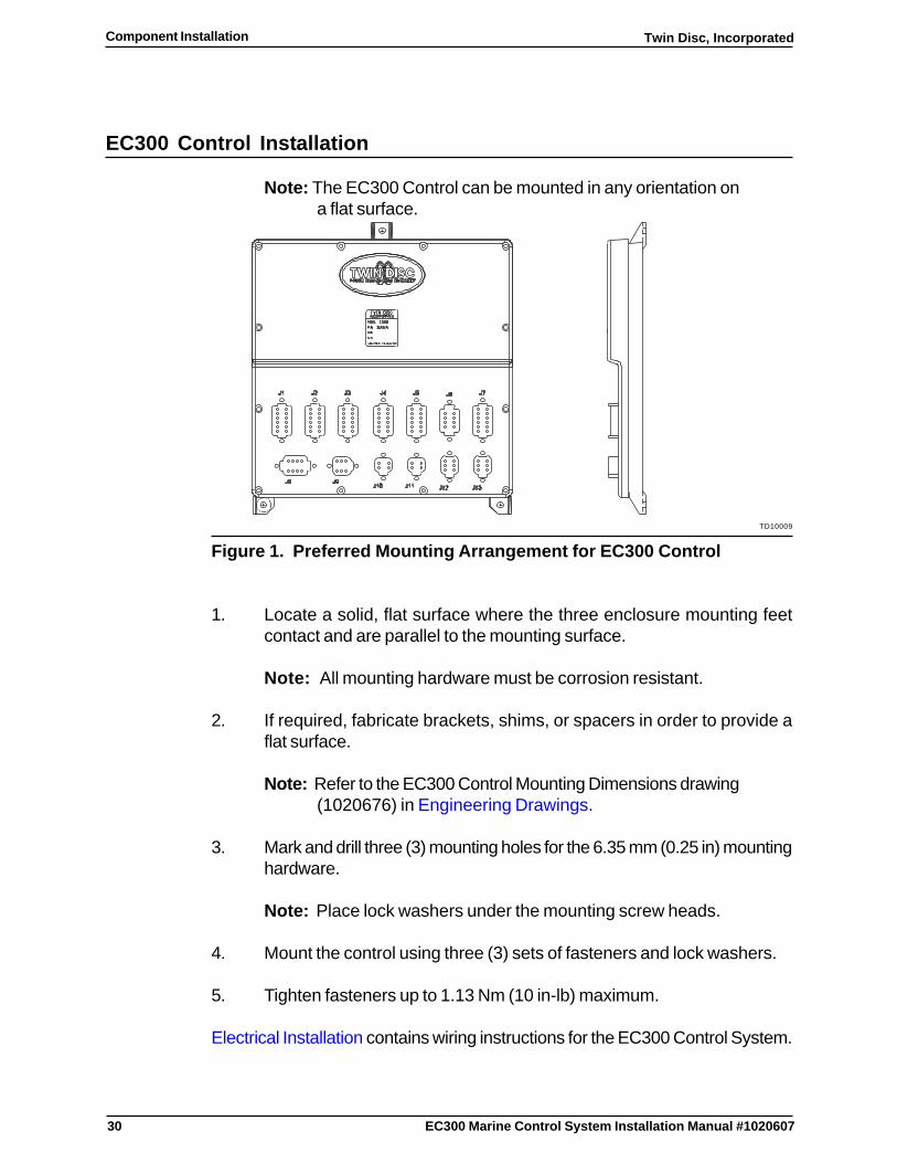
Note: The EC300 Control can be mounted in any orientation ona flat surface.
TD10009
Figure 1. Preferred Mounting Arrangement for EC300 Control
1. Locate a solid, flat surface where the three enclosure mounting feetcontact and are parallel to the mounting surface.
Note: All mounting hardware must be corrosion resistant.
2. If required, fabricate brackets, shims, or spacers in order to provide aflat surface.
Note: Refer to the EC300 Control Mounting Dimensions drawing(1020676) in Engineering Drawings.
3. Mark and drill three (3) mounting holes for the 6.35 mm (0.25 in) mountinghardware.
Note: Place lock washers under the mounting screw heads.
4. Mount the control using three (3) sets of fasteners and lock washers.
5. Tighten fasteners up to 1.13 Nm (10 in-lb) maximum.
Electrical Installation contains wiring instructions for the EC300 Control System.

31
Twin Disc, Incorporated Component Installation
EC300 Marine Control System Installation Manual #1020607
Control Head Installation
A control station is a location from which the boat can be operated. A controlstation will consist of one or more Control Heads. Each control station requiresthe installation of a Control Head and associated wiring harnesses. The controlstation may consist of a single or dual lever Control Head, multiple ControlHeads, or side mount Control Head Assembly. There are separate instructionsfor the single/dual lever Control Head and the side mount Control HeadAssembly.
Note: Only EC300 Control Heads will work with the EC300Control. The older EC200 Control Heads are notcompatible.
Note: Chrome plated Control Heads should be polishedperiodically using a chrome polish to help retardcorrosion.
Single/Dual Lever Control Head
The Control Head may be either a single or dual lever version. This installationprocedure applies to both versions.
STATION
SELECT
PORTR
STBD
TWIN DISC
NCRUISE
P0WER COMMANDER
GEAR SHIFTER IS IN
NEUTRAL POSITION
WHEN INDICATOR ON.
EC300R
SYNC TROLLEXPRESS
N
R
TD10103
STBDLEVER
NEUTRALINDICATOR LED(2 PLACES)
STATION SELECTINDICATOR LED(2 PLACES)
STATIONSELECTBUTTON
PORTLEVER
MODESELECTSWITCH
TD10010
Figure 2. Front View of Dual Lever Control Head With Levers in NeutralPosition
32
Twin Disc, IncorporatedComponent Installation
EC300 Marine Control System Installation Manual #1020607
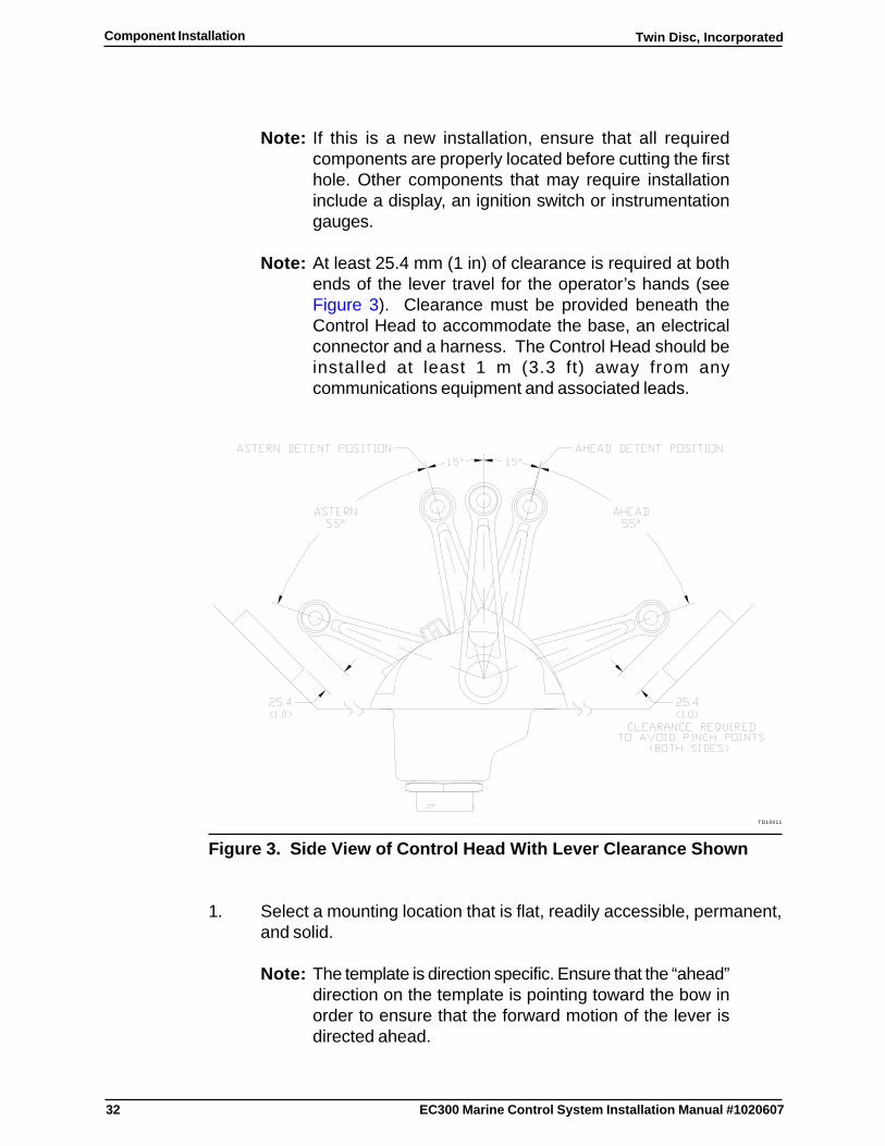
Note: If this is a new installation, ensure that all requiredcomponents are properly located before cutting the firsthole. Other components that may require installationinclude a display, an ignition switch or instrumentationgauges.
Note: At least 25.4 mm (1 in) of clearance is required at bothends of the lever travel for the operator’s hands (seeFigure 3). Clearance must be provided beneath theControl Head to accommodate the base, an electricalconnector and a harness. The Control Head should beinstalled at least 1 m (3.3 ft) away from anycommunications equipment and associated leads.
TD10011
Figure 3. Side View of Control Head With Lever Clearance Shown
1. Select a mounting location that is flat, readily accessible, permanent,and solid.
Note: The template is direction specific. Ensure that the “ahead”direction on the template is pointing toward the bow inorder to ensure that the forward motion of the lever isdirected ahead.

33
Twin Disc, Incorporated Component Installation
EC300 Marine Control System Installation Manual #1020607
2. Cut out the Control Head Mounting Template in Engineering Drawingsand tape it in the desired location.
3. Make sure this position provides clearance for the operator’s handsover the full range of lever travel.
4. Center punch the four (4) mounting holes and scribe the base cutoutoutline.
5. Remove the template.
Note: The hole cannot be smaller than shown on the templateand must be properly aligned with the mounting holes.
6. Drill and cut the holes using the template markings.
7. Check the hole locations with the template.
8. Remove any splinters or sharp edges from the holes.
9. Carefully place the Control Head in the hole.
10. Check the fit of holes.
11. Remove the Control Head from the cutout.
12. If required, correct the fit.
Note: Drag adjustment is provided at each lever. Properadjustment is necessary to ensure that the lever remainsin the intended position without operator assistance.
13. Set drag per Control Head Lever Drag Adjustment.

34
Twin Disc, IncorporatedComponent Installation
EC300 Marine Control System Installation Manual #1020607
Side Mount Control Head Assembly (Binnacle/Console Station)
The side mount Control Head Assembly consists of a Lever, Interface Assembly,Interface harness and Selector Assembly. The lever may be supplied by TwinDisc or other sources. Specific lever attachment instructions should be suppliedwith the lever and the lever must be capable of attaching to the 15.87 mm(0 .625 in) diameter shaft of the Interface Assembly. The Interface Assemblycomes with a mounting plate for sandwiching the console wall between theassembly and the mounting plate. The Selector Assembly mounts directly tothe surface of the console.
1. Locate a position on the side of the console which provides the operatorwith unrestricted access to the lever(s), while providing full range (70degrees either side of neutral) of lever motion.
2. Locate a position on the top or front surface of the console which providesunrestricted access to the Selector Assembly indicators and ModeSelect Switch. Confirm that the desired location will allow the InterfaceHarness to reach between the Interface Assembly and the SelectorAssembly.
TD10200
Figure 4. Side Mount Control Head Assembly
35
Twin Disc, Incorporated Component Installation
EC300 Marine Control System Installation Manual #1020607
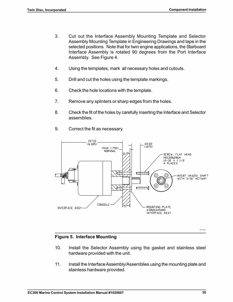
3. Cut out the Interface Assembly Mounting Template and SelectorAssembly Mounting Template in Engineering Drawings and tape in theselected positions. Note that for twin engine applications, the StarboardInterface Assembly is rotated 90 degrees from the Port InterfaceAssembly. See Figure 4.
4. Using the templates, mark all necessary holes and cutouts.
5. Drill and cut the holes using the template markings.
6. Check the hole locations with the template.
7. Remove any splinters or sharp edges from the holes.
8. Check the fit of the holes by carefully inserting the Interface and Selectorassemblies.
9. Correct the fit as necessary.
TD10201
Figure 5. Interface Mounting
10. Install the Selector Assembly using the gasket and stainless steelhardware provided with the unit.
11. Install the Interface Assembly/Assemblies using the mounting plate andstainless hardware provided.

36
Twin Disc, IncorporatedComponent Installation
EC300 Marine Control System Installation Manual #1020607
12. Connect the Interface Harness between the Interface Assembly and theSelector Assembly and secure/strain relieve as necessary.
13. Attach the Lever to the 15.87 mm (0 .625 in) diameter shaft of theInterface Assembly, following the instructions provided with the lever.
37
Twin Disc, Incorporated Component Installation
EC300 Marine Control System Installation Manual #1020607
Control Head Lever Drag Adjustment
TD10013
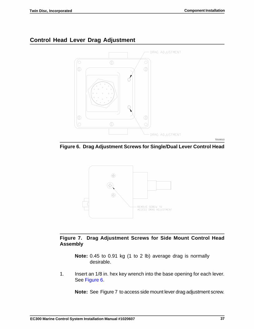
Figure 6. Drag Adjustment Screws for Single/Dual Lever Control Head
Figure 7. Drag Adjustment Screws for Side Mount Control HeadAssembly
Note: 0.45 to 0.91 kg (1 to 2 lb) average drag is normallydesirable.
1. Insert an 1/8 in. hex key wrench into the base opening for each lever.See Figure 6.
Note: See Figure 7 to access side mount lever drag adjustment screw.

38
Twin Disc, IncorporatedComponent Installation
EC300 Marine Control System Installation Manual #1020607
2. Tighten the drag adjustment screw(s) until the desired drag is obtainedover the full lever travel.
Note: All fastening hardware must be corrosion resistant.
Note: The type of fastener to be used depends on material usedfor the support. Each Control Head is supplied withstainless steel 38 mm (1.5 in) screws suitable for mountingin a dash up to 19 mm (0.75 in) thick. Use the appropriatefastener for the specific installation.
3. Install and mount the Control Head using the supplied gasket and four(4) oval head #10 screws or equivalent.
4. Torque the fasteners to 1.13 Nm (10 in-lb) maximum.
Control Head Harness (J1, J2, or J3) Installation addresses Control Headharness wiring installation.
39
Twin Disc, Incorporated Component Installation
EC300 Marine Control System Installation Manual #1020607
Station Doubler Installation
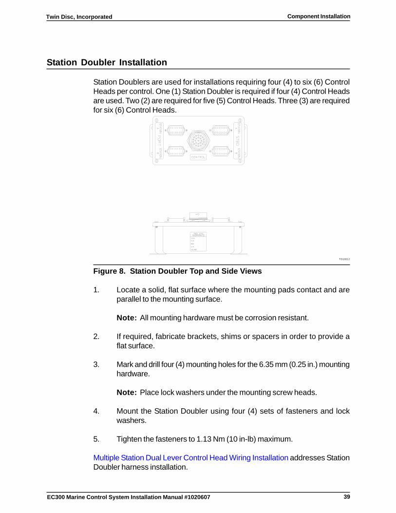
Station Doublers are used for installations requiring four (4) to six (6) ControlHeads per control. One (1) Station Doubler is required if four (4) Control Headsare used. Two (2) are required for five (5) Control Heads. Three (3) are requiredfor six (6) Control Heads.
TD10012
Figure 8. Station Doubler Top and Side Views
1. Locate a solid, flat surface where the mounting pads contact and areparallel to the mounting surface.
Note: All mounting hardware must be corrosion resistant.
2. If required, fabricate brackets, shims or spacers in order to provide aflat surface.
3. Mark and drill four (4) mounting holes for the 6.35 mm (0.25 in.) mountinghardware.
Note: Place lock washers under the mounting screw heads.
4. Mount the Station Doubler using four (4) sets of fasteners and lockwashers.
5. Tighten the fasteners to 1.13 Nm (10 in-lb) maximum.
Multiple Station Dual Lever Control Head Wiring Installation addresses StationDoubler harness installation.
40
Twin Disc, IncorporatedComponent Installation
EC300 Marine Control System Installation Manual #1020607
Engine Speed Sensor Installation
Installations with options such as engine syncronization (Sync Mode), ExpressMode, and Troll Mode (with speed feedback) require engine speed sensors.There are many types of sensors available. Many will work with the EC300Control System. This section outlines the installation of the sensors availablefrom Twin Disc. Contact Twin Disc Incorporated or the nearest distributor forthe possible use of other sensors.
The following speed signal generators are covered:
� Speed Sensor including the use of a dual output Speed Sensor
� Tachometer Signal Generator
Speed Sensor Installation
Note: Newer Twin Disc Incorporated transmissions haveintegrated input speed sensors as a standard option.
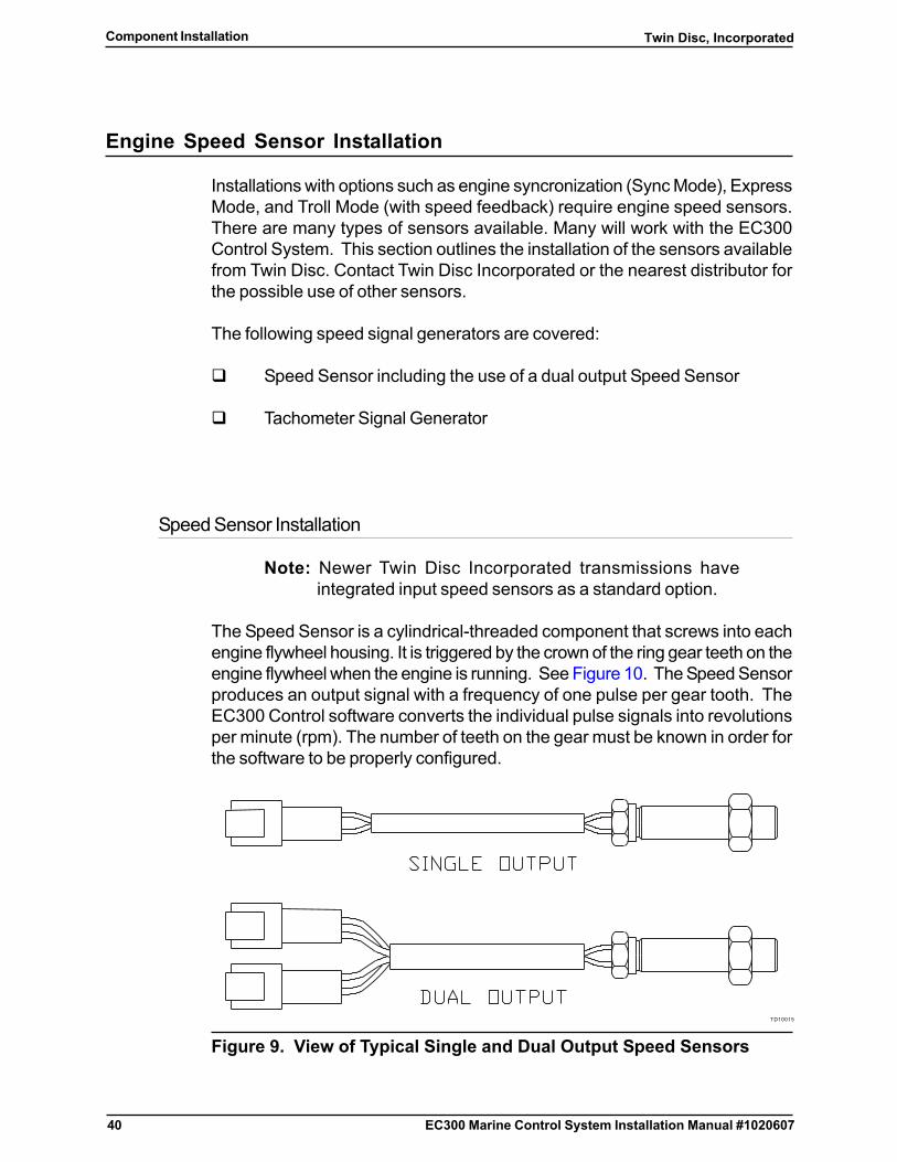
The Speed Sensor is a cylindrical-threaded component that screws into eachengine flywheel housing. It is triggered by the crown of the ring gear teeth on theengine flywheel when the engine is running. See Figure 10. The Speed Sensorproduces an output signal with a frequency of one pulse per gear tooth. TheEC300 Control software converts the individual pulse signals into revolutionsper minute (rpm). The number of teeth on the gear must be known in order forthe software to be properly configured.
TD10015
Figure 9. View of Typical Single and Dual Output Speed Sensors
41
Twin Disc, Incorporated Component Installation
EC300 Marine Control System Installation Manual #1020607
Note: Single output Speed Sensors are preferred. See Figure9. Dual output Speed Sensors are acceptable if theoutputs are electrically isolated from each other and havethe required electrical characteristics.
TD10014
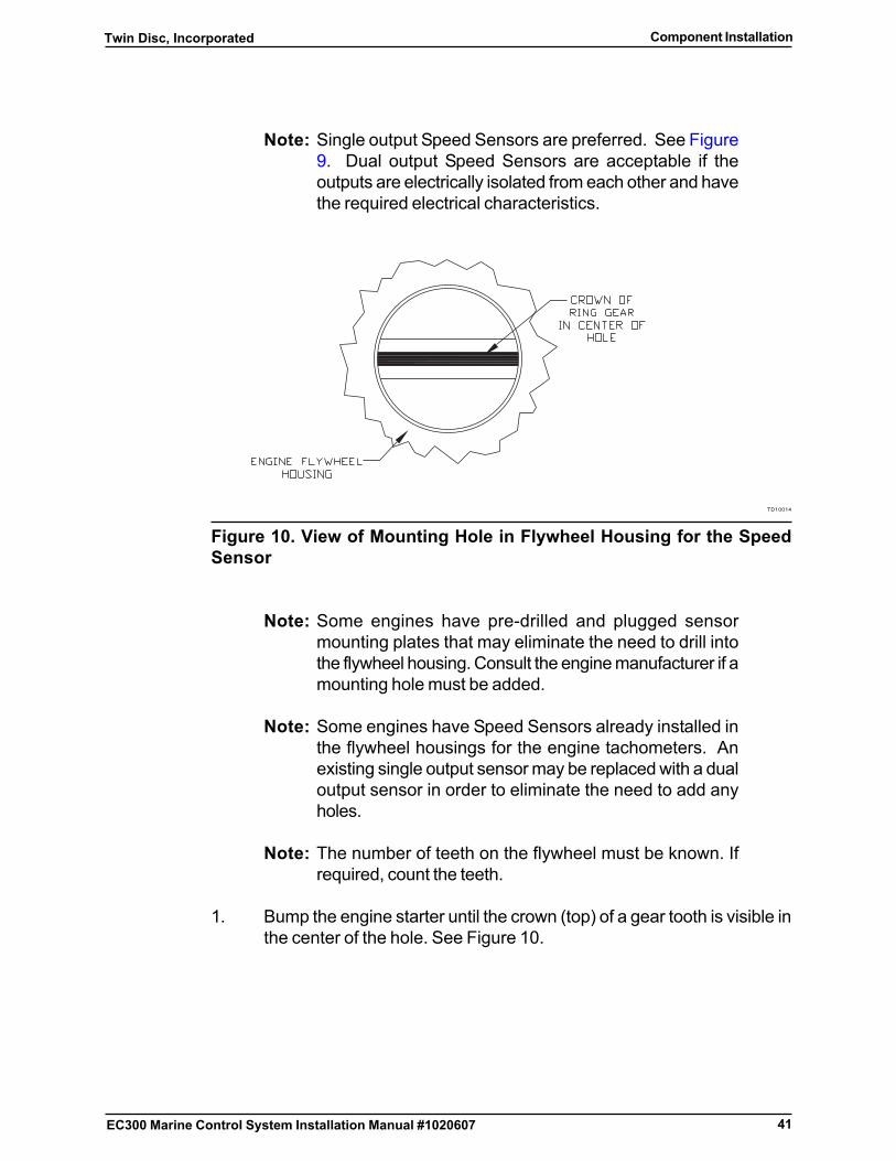
Figure 10. View of Mounting Hole in Flywheel Housing for the SpeedSensor
Note: Some engines have pre-drilled and plugged sensormounting plates that may eliminate the need to drill intothe flywheel housing. Consult the engine manufacturer if amounting hole must be added.
Note: Some engines have Speed Sensors already installed inthe flywheel housings for the engine tachometers. Anexisting single output sensor may be replaced with a dualoutput sensor in order to eliminate the need to add anyholes.
Note: The number of teeth on the flywheel must be known. Ifrequired, count the teeth.
1. Bump the engine starter until the crown (top) of a gear tooth is visible inthe center of the hole. See Figure 10.
42
Twin Disc, IncorporatedComponent Installation
EC300 Marine Control System Installation Manual #1020607
CAUTIONDo not use too much oil. Dirt will collect on the sensing face and makethe Speed Sensor malfunction.
2. Coat the Speed Sensor threads with a very thin film of oil.
3. Install the Speed Sensor in the hole finger-tight against the ring gear.
4. Back out the Speed Sensor one-half turn and tighten the lock nut to 4.52Nm (40 in-lb) maximum against the flywheel housing while holding theSpeed Sensor body in place.
5. If using a dual-output Speed Sensor, reconnect the original signal cableto one of the sensor outputs.
Cable installation is completed in Electrical Installation.
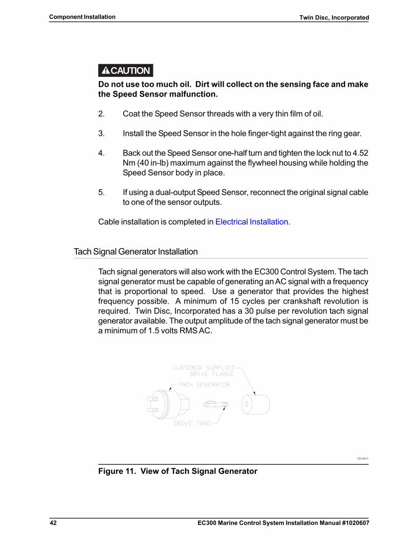
Tach Signal Generator Installation
Tach signal generators will also work with the EC300 Control System. The tachsignal generator must be capable of generating an AC signal with a frequencythat is proportional to speed. Use a generator that provides the highestfrequency possible. A minimum of 15 cycles per crankshaft revolution isrequired. Twin Disc, Incorporated has a 30 pulse per revolution tach signalgenerator available. The output amplitude of the tach signal generator must bea minimum of 1.5 volts RMS AC.
TD10017
Figure 11. View of Tach Signal Generator

43
Twin Disc, Incorporated Component Installation
EC300 Marine Control System Installation Manual #1020607
Note: Mechanical drive components that are necessary toconvert an existing tach sender drive to a dual tach senderdrive must be ordered from the accessory supplieridentified on the existing tach sender.
CAUTIONThe tach signal generator output used for the EC300 Marine ControlSystem cannot be used to provide signals to other devices on the vessel.The signal generator output used must be connected directly to theEC300 Control.
Install the tach signal generator as per the manufacturer’s instructions.
Reference Engine Control Harness Installation for Cable Installation.
Note: The number of pulses per revolution must be known inorder for the EC300 control software to be properlyconfigured.
44
Twin Disc, IncorporatedComponent Installation
EC300 Marine Control System Installation Manual #1020607
Servo Actuator Installation
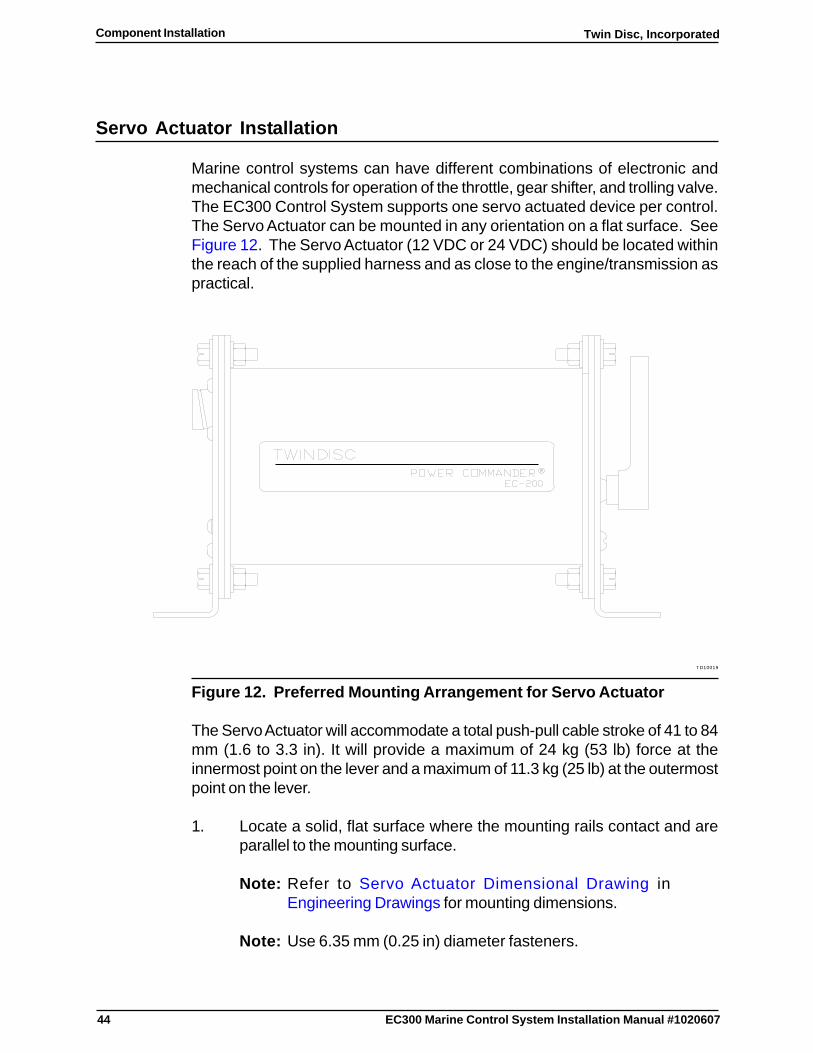
Marine control systems can have different combinations of electronic andmechanical controls for operation of the throttle, gear shifter, and trolling valve.The EC300 Control System supports one servo actuated device per control.The Servo Actuator can be mounted in any orientation on a flat surface. SeeFigure 12. The Servo Actuator (12 VDC or 24 VDC) should be located withinthe reach of the supplied harness and as close to the engine/transmission aspractical.
TD10019
Figure 12. Preferred Mounting Arrangement for Servo Actuator
The Servo Actuator will accommodate a total push-pull cable stroke of 41 to 84mm (1.6 to 3.3 in). It will provide a maximum of 24 kg (53 lb) force at theinnermost point on the lever and a maximum of 11.3 kg (25 lb) at the outermostpoint on the lever.
1. Locate a solid, flat surface where the mounting rails contact and areparallel to the mounting surface.
Note: Refer to Servo Actuator Dimensional Drawing inEngineering Drawings for mounting dimensions.
Note: Use 6.35 mm (0.25 in) diameter fasteners.

45
Twin Disc, Incorporated Component Installation
EC300 Marine Control System Installation Manual #1020607
Note: All mounting hardware must be corrosion resistant.
2. If required, fabricate brackets, shims or spacers in order to provide aflat surface.
3. Mark and drill the four mounting holes for the 6.35 mm (0.25 in) mountinghardware.
Note: Place lock washers under the mounting screw heads.
4. Mount the Servo Actuator using four sets of fasteners and lock washers.
5. Install the push-pull cable. See Push-Pull Cable Installation.

46
Twin Disc, IncorporatedComponent Installation
EC300 Marine Control System Installation Manual #1020607
Push-Pull Cable Installation
Introduction
Correct push-pull cable installation will aid in trouble-free operation andmaintenance of the control system. Different installation kits are available. Usingquick-disconnect ball joints will aid in push-pull cable adjustment.
This section contains the following sub-sections:
� Push-Pull Cable Installation Kits for Conductive Vessels
� Push-Pull Cable Installation Kits for Nonconductive Vessels
� Push-Pull Cable Installation Guidelines
� Push-Pull Cable Installation
Push-Pull Cable Installation Kits for Conductive Vessels
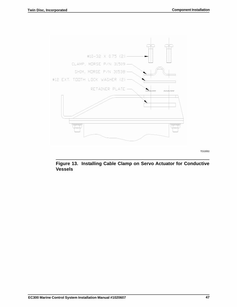
Quick-disconnect ball joint kits or terminal eye pins with cable clamps for Morse33 series push-pull cables are available from Twin Disc Incorporated. SeeFigure 13 and Figure 14. The dual kit accommodates one end of two cables.The single kit accommodates one end of one cable. Each Servo Actuatorrequires a single kit to connect the cable to the Servo Actuator. Refer to Morse33 Series Cable Mounting Dimensions in Engineering Drawings for additionalinformation.
47
Twin Disc, Incorporated Component Installation
EC300 Marine Control System Installation Manual #1020607
TD10053
Figure 13. Installing Cable Clamp on Servo Actuator for ConductiveVessels
48
Twin Disc, IncorporatedComponent Installation
EC300 Marine Control System Installation Manual #1020607
TD10054
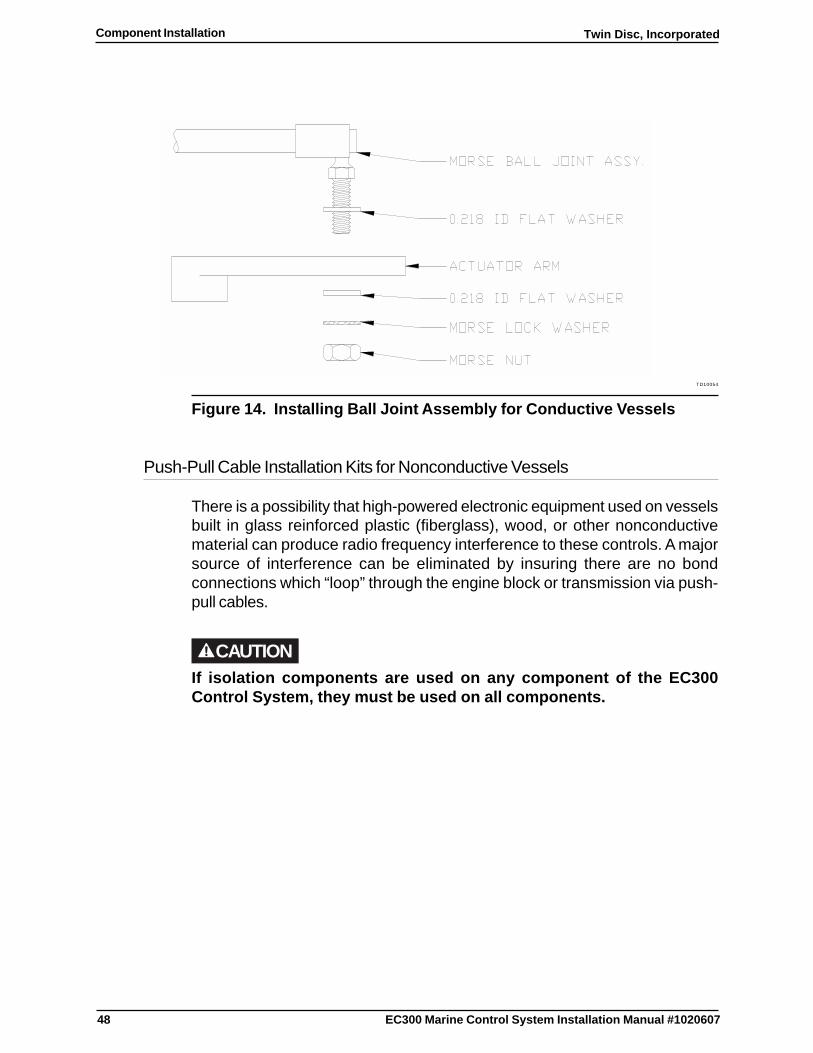
Figure 14. Installing Ball Joint Assembly for Conductive Vessels
Push-Pull Cable Installation Kits for Nonconductive Vessels
There is a possibility that high-powered electronic equipment used on vesselsbuilt in glass reinforced plastic (fiberglass), wood, or other nonconductivematerial can produce radio frequency interference to these controls. A majorsource of interference can be eliminated by insuring there are no bondconnections which “loop” through the engine block or transmission via push-pull cables.
CAUTIONIf isolation components are used on any component of the EC300Control System, they must be used on all components.
49
Twin Disc, Incorporated Component Installation
EC300 Marine Control System Installation Manual #1020607
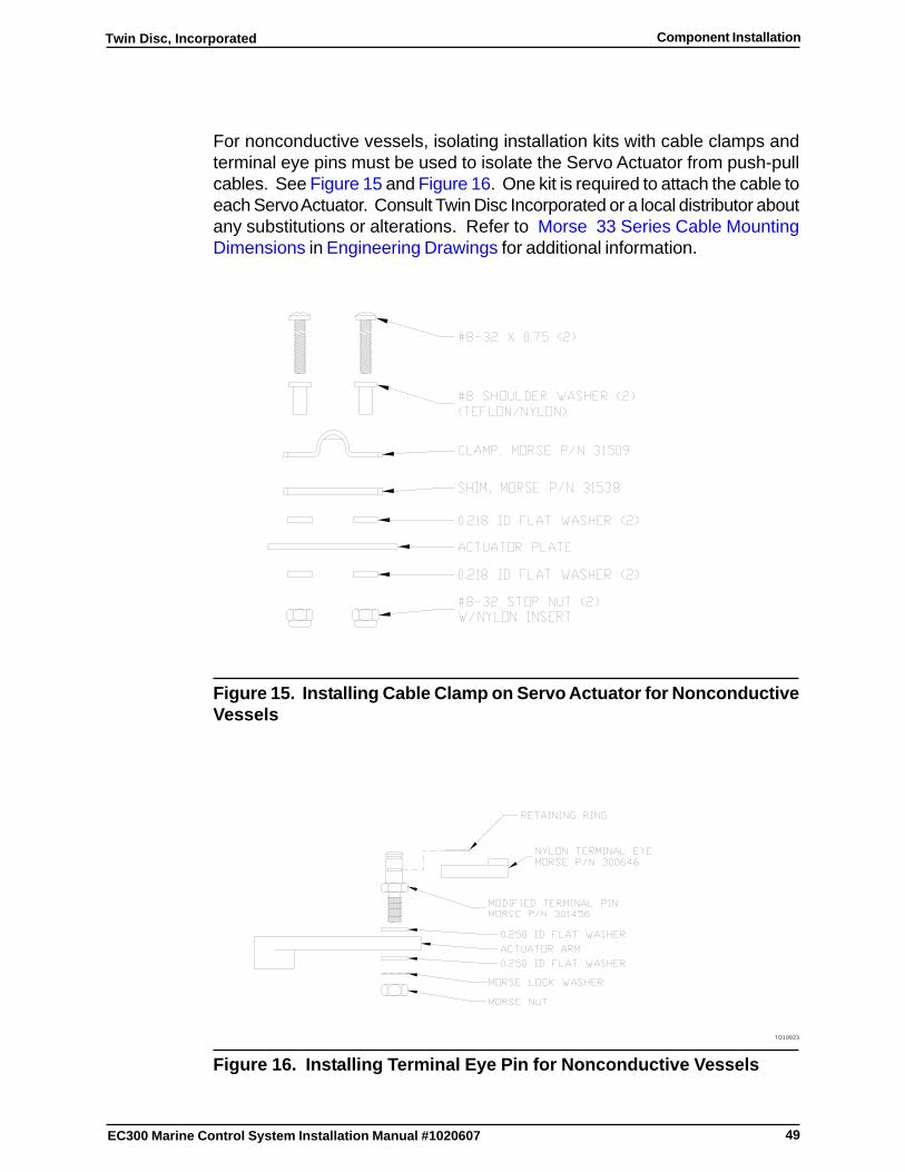
For nonconductive vessels, isolating installation kits with cable clamps andterminal eye pins must be used to isolate the Servo Actuator from push-pullcables. See Figure 15 and Figure 16. One kit is required to attach the cable toeach Servo Actuator. Consult Twin Disc Incorporated or a local distributor aboutany substitutions or alterations. Refer to Morse 33 Series Cable MountingDimensions in Engineering Drawings for additional information.
Figure 15. Installing Cable Clamp on Servo Actuator for NonconductiveVessels
TD10023
Figure 16. Installing Terminal Eye Pin for Nonconductive Vessels

50
Twin Disc, IncorporatedComponent Installation
EC300 Marine Control System Installation Manual #1020607
Push-Pull Cable Installation Guidelines
Push-pull cable installation should meet the following guidelines:
� Cables must be Morse 33 Series RED JAKET® Supreme or equivalent.
� A minimal number of bends should be used.
� Bends should use the maximum possible radius where bends arerequired.
� Cables should not be routed near hot surfaces.
� Cables should not be routed in service or access areas.
Push-Pull Cable Installation
This section describes how to install the push-pull cable for a mechanicallyshifted transmission, for a mechanically controlled throttle, and for amechanically controlled troll actuator.
TD10024
Figure 17. Servo Actuator Push-Pull Cable Installation
51
Twin Disc, Incorporated Component Installation
EC300 Marine Control System Installation Manual #1020607
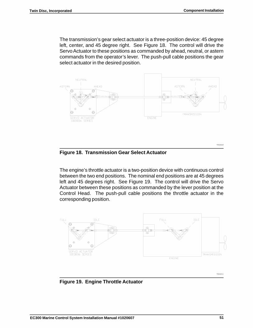
The transmission’s gear select actuator is a three-position device: 45 degreeleft, center, and 45 degree right. See Figure 18. The control will drive theServo Actuator to these positions as commanded by ahead, neutral, or asterncommands from the operator’s lever. The push-pull cable positions the gearselect actuator in the desired position.
TD10210
Figure 18. Transmission Gear Select Actuator
The engine’s throttle actuator is a two-position device with continuous controlbetween the two end positions. The nominal end positions are at 45 degreesleft and 45 degrees right. See Figure 19. The control will drive the ServoActuator between these positions as commanded by the lever position at theControl Head. The push-pull cable positions the throttle actuator in thecorresponding position.
TD10211
Figure 19. Engine Throttle Actuator

52
Twin Disc, IncorporatedComponent Installation
EC300 Marine Control System Installation Manual #1020607
The transmission’s troll valve actuator is a two-position device with nominalpositions at 45 degree left and 45 degree right rotation. See Figure 20. TheControl will drive the Servo Actuator to these positions as commanded by leverposition at the Control Head. The push-pull cable positions the troll valve in thedesired position.
TD10212
Figure 20. Transmission Troll Valve Actuator
Note: Neither the engine’s nor the transmission’s push-pull clampand bracket are supplied.
Note: This process should be read and understood prior toinstallation of Servo Actuator and related components, toensure all component mounting positions are locatedproperly and all necessary materials are available forcomplete installation.
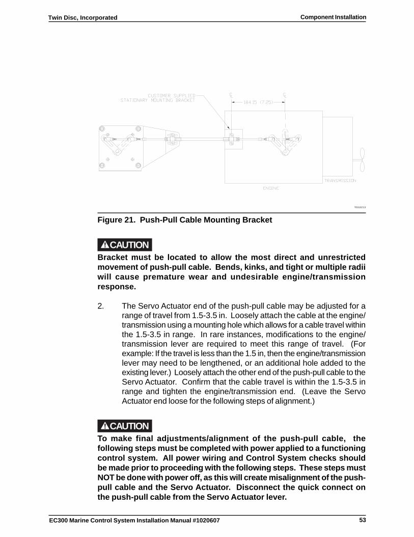
1. Fabricate push-pull cable mounting bracket as needed, to attach/clampthe cable to the engine or transmission. The critical dimension is 7.25inches from centerline of clamp mounting holes to centerline of engine/transmission lever. See Figure 21. Secure bracket to engine/transmission.
53
Twin Disc, Incorporated Component Installation
EC300 Marine Control System Installation Manual #1020607
TD10213
Figure 21. Push-Pull Cable Mounting Bracket
CAUTIONBracket must be located to allow the most direct and unrestrictedmovement of push-pull cable. Bends, kinks, and tight or multiple radiiwill cause premature wear and undesirable engine/transmissionresponse.
2. The Servo Actuator end of the push-pull cable may be adjusted for arange of travel from 1.5-3.5 in. Loosely attach the cable at the engine/transmission using a mounting hole which allows for a cable travel withinthe 1.5-3.5 in range. In rare instances, modifications to the engine/transmission lever are required to meet this range of travel. (Forexample: If the travel is less than the 1.5 in, then the engine/transmissionlever may need to be lengthened, or an additional hole added to theexisting lever.) Loosely attach the other end of the push-pull cable to theServo Actuator. Confirm that the cable travel is within the 1.5-3.5 inrange and tighten the engine/transmission end. (Leave the ServoActuator end loose for the following steps of alignment.)
CAUTIONTo make final adjustments/alignment of the push-pull cable, thefollowing steps must be completed with power applied to a functioningcontrol system. All power wiring and Control System checks shouldbe made prior to proceeding with the following steps. These steps mustNOT be done with power off, as this will create misalignment of the push-pull cable and the Servo Actuator. Disconnect the quick connect onthe push-pull cable from the Servo Actuator lever.
54
Twin Disc, IncorporatedComponent Installation
EC300 Marine Control System Installation Manual #1020607
3. The Control Head levers and Mode Select Switch will have to bemanipulated for the following activities. Power up the Control Systemand take command of the Control Head. Use the Control Head closestto where the Servo Actuator is located, or have one person commandthe Control Head while another monitors and adjusts the push-pull cableat the Servo Actuator.
Engine Servo Actuator (Throttle):
A: Position Control Head lever for Idle/Neutral. The Servo Actuatorlever will move to the idle position.
B: Position engine lever to Idle. The attached push-pull cable will moveaccordingly.
C: Make note of the push-pull cable position at the Servo Actuator end,comparing the location of the cable end to the Servo Actuator lever.Using a piece of tape and pen/marker, mark the Servo Actuator with theposition of the cable end.
D: Repeat with the Control Head lever in Full Throttle position. TheServo Actuator lever will move to the full throttle position.
Transmission Servo Actuator (FWD/NEU/REV):
A: Position Control Head lever for Forward Detent. The Servo Actuatorlever will move to the Forward position.
B: Position the transmission lever to Forward Detent. The attachedpush-pull cable will move accordingly.
C: Make note of the push-pull cable position at the Servo Actuator end,comparing the location of the cable to the Servo Actuator lever. Using apiece of tape and pen/marker, mark the Servo Actuator with the positionof the cable end.
D: Repeat with the Control Head lever in the Reverse Detent. TheServo Actuator will move to the Reverse position.
Note: When you adjust the push-pull cable travel for Forwardand Reverse positions, Neutral will automatically becentered. However, you cannot adjust the push-pull cablefor Neutral and then assume the Forward and Reversepositions will be aligned.
55
Twin Disc, Incorporated Component Installation
EC300 Marine Control System Installation Manual #1020607
Transmission Servo Actuator (TROLL):
A: Position Control Head lever for Neutral Detent and the Mode SelectSwitch to TROLL. The Servo Actuator will move to the Full Slip/Trollposition.
B: Position the transmission trolling lever to Full Slip/Troll. The attachedpush-pull cable will move accordingly.
C: Make note of the push-pull cable position at the Servo Actuator end,comparing the location of the cable end to the Servo Actuator lever.Using a piece of tape and pen/marker, mark the Servo Actuator with theposition of the cable end.
D: Repeat with the Control Head Mode Select Switch in CRUISE. TheServo Actuator will move to the Lockup/Cruise position.
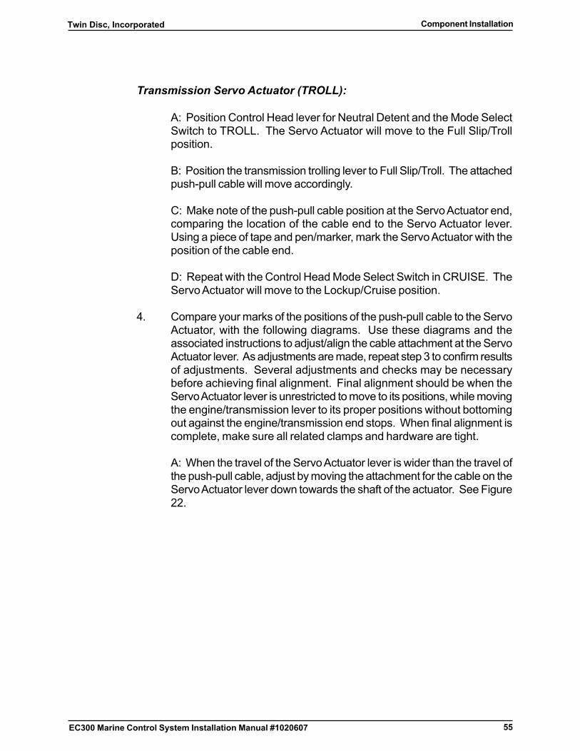
4. Compare your marks of the positions of the push-pull cable to the ServoActuator, with the following diagrams. Use these diagrams and theassociated instructions to adjust/align the cable attachment at the ServoActuator lever. As adjustments are made, repeat step 3 to confirm resultsof adjustments. Several adjustments and checks may be necessarybefore achieving final alignment. Final alignment should be when theServo Actuator lever is unrestricted to move to its positions, while movingthe engine/transmission lever to its proper positions without bottomingout against the engine/transmission end stops. When final alignment iscomplete, make sure all related clamps and hardware are tight.
A: When the travel of the Servo Actuator lever is wider than the travel ofthe push-pull cable, adjust by moving the attachment for the cable on theServo Actuator lever down towards the shaft of the actuator. See Figure22.
56
Twin Disc, IncorporatedComponent Installation
EC300 Marine Control System Installation Manual #1020607
TD10214
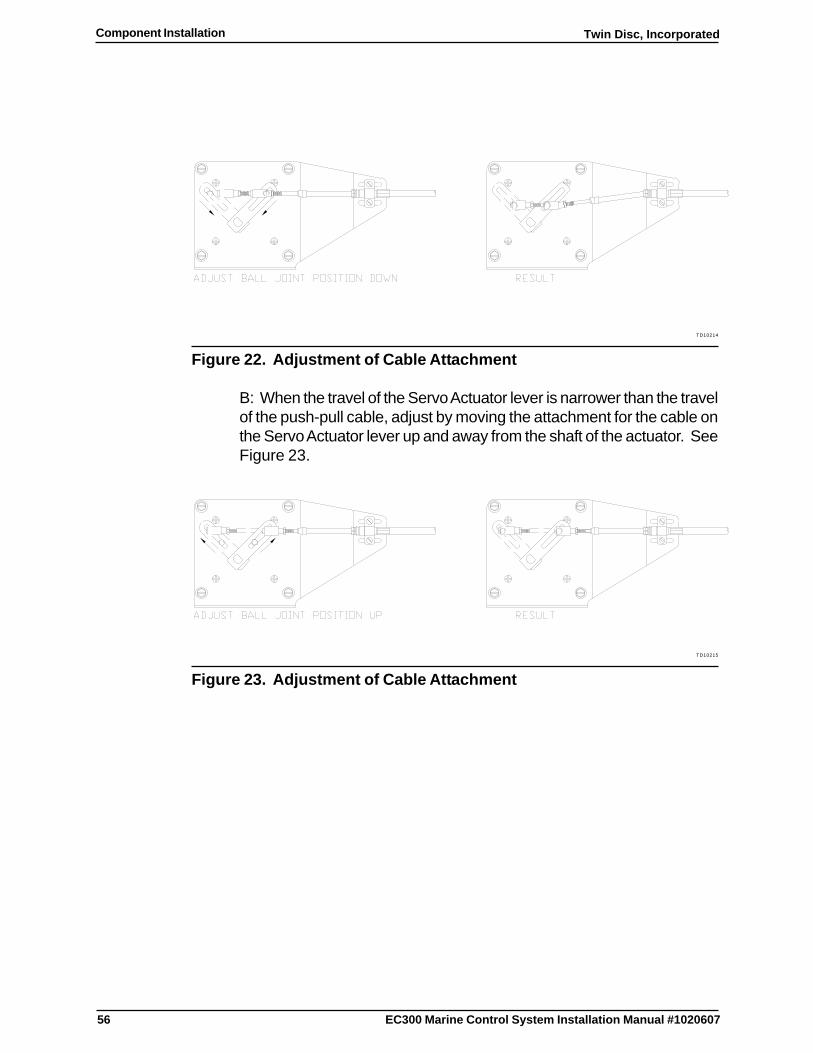
Figure 22. Adjustment of Cable Attachment
B: When the travel of the Servo Actuator lever is narrower than the travelof the push-pull cable, adjust by moving the attachment for the cable onthe Servo Actuator lever up and away from the shaft of the actuator. SeeFigure 23.
TD10215
Figure 23. Adjustment of Cable Attachment

57
Twin Disc, Incorporated Component Installation
EC300 Marine Control System Installation Manual #1020607
C: When the travel of the Servo Actuator lever and push-pull cablematches closely, however the cable will not reach to attach to the ServoActuator Lever at both ends of travel, move the cable clamp inwardstowards the actuator lever. See Figure 24.
TD10216
Figure 24. Adjustment of Cable Clamp - Short
D: When the travel of the Servo Actuator lever and push-pull cablematches closely; however, the cable overshoots the Servo Actuator leverat both ends of travel, moving the cable clamp outwards away from theactuator lever. See Figure 25.
TD10217
Figure 25. Adjustment of Cable Clamp - Overshoot
Note: Electrical harness installation for the Servo Actuator iscompleted in Electrical Installation.
58
Twin Disc, IncorporatedComponent Installation
EC300 Marine Control System Installation Manual #1020607
Twin Disc Display Installation
TD10025
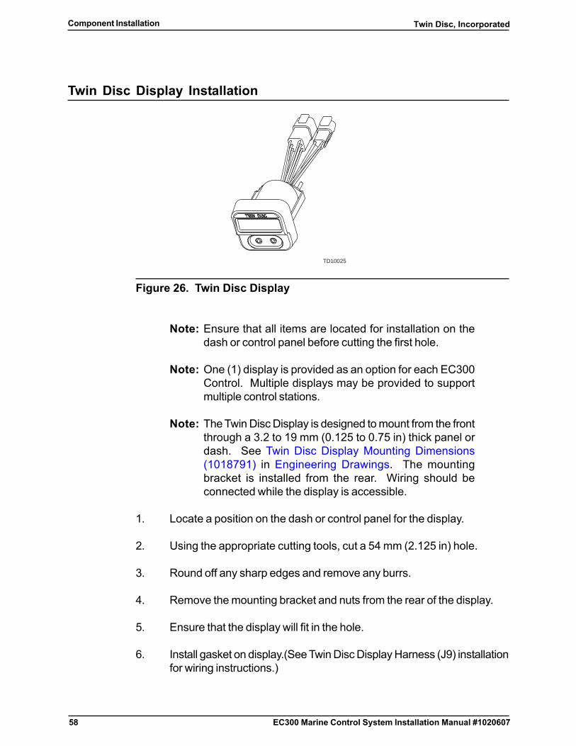
Figure 26. Twin Disc Display
Note: Ensure that all items are located for installation on thedash or control panel before cutting the first hole.
Note: One (1) display is provided as an option for each EC300Control. Multiple displays may be provided to supportmultiple control stations.
Note: The Twin Disc Display is designed to mount from the frontthrough a 3.2 to 19 mm (0.125 to 0.75 in) thick panel ordash. See Twin Disc Display Mounting Dimensions(1018791) in Engineering Drawings. The mountingbracket is installed from the rear. Wiring should beconnected while the display is accessible.
1. Locate a position on the dash or control panel for the display.
2. Using the appropriate cutting tools, cut a 54 mm (2.125 in) hole.
3. Round off any sharp edges and remove any burrs.
4. Remove the mounting bracket and nuts from the rear of the display.
5. Ensure that the display will fit in the hole.
6. Install gasket on display.(See Twin Disc Display Harness (J9) installationfor wiring instructions.)

59
Twin Disc, Incorporated Component Installation
EC300 Marine Control System Installation Manual #1020607
7. Insert the display in the dash or control panel.
8. Attach the mounting bracket and tighten the nuts until the display is firmlysecured in the dash.
9. If applicable, repeat steps 1 through 8 for each additional display.
Twin Disc Display Harness (J9) Installation addresses display harness wiringinstallation.

60
Twin Disc, IncorporatedComponent Installation
EC300 Marine Control System Installation Manual #1020607
Lever Function Switch Installation
The lever function toggle switch is used in certain applications for the EC300Control System. The switch can be used to enable Master Lever or Phantomlever modes depending upon the selected options. This instruction providesinformation related to the installation of a typical toggle switch. Refer to themanufacturer’s literature for any custom switch installation requirements.
Note: Ensure that all items are located for installation on thedash or control panel before cutting the first hole.
Note: The typical toggle switch is designed to mount from therear of the panel or dash. The mounting nut is installedfrom the front.
TD10026
Figure 27. Typical Enable Toggle Switch
1. Locate a position on the dash or control panel for the switch.
2. Using the appropriate cutting tools, cut a mounting hole of the requiredsize.
3. Round off any sharp edges and remove any burrs.
4. Remove the mounting nut from the front of the switch.
5. Insert the switch and any legend plate in the dash or control panel.
6. Install and tighten the nut until the switch is firmly contacting the dash orpanel.
Lever Function Switch Wiring addresses Miscellaneous Bridge SignalsConnector Kit (J8) wiring installation.

61
Twin Disc, Incorporated Electrical Installation
EC300 Marine Control System Installation Manual #1020607
Electrical Installation
Introduction
Harnesses and Connectors
The EC300 Control System is provided with prefabricated cable harnesseswith pre-installed connectors in order to reduce installation time and errors. Insome cases, only the EC300 end of the harness has a pre-installed connector.In other cases, the EC300 connector is supplied by Twin Disc Incorporatedand the cable and far-end connectors are supplied by the customer.
Note the following when making connections:
q The installer must provide suitable wire cable and crimping tools, Deutschcrimp tool (P/N HDT 48-00). Use all tools and materials in accordancewith manufacturer’s instructions. See Required Tools and Table 4.
q The installer must follow the print provided for the system.
q Cables should never be installed in a manner which puts strain on theconnector or which results in more than 610 mm (24 in) of excess length.
q A service loop or drip leg should be provided in each cable at the EC300Control. Service loops should be tied down so that they do not movefreely when the boat is in motion. Excess motion can cause the wiringto fatigue and break.
q The connectors have a resilient insert that seals to the insulation of eachwire in the connector. Do not attempt to fit two wires into any of theconnector positions. Sealing plugs are provided for unused positionsof the connector in order to insure the sealed nature of the connectedcable assembly. Do not discard these white plastic plugs since theymust be inserted into the unused positions.
q For harness kits that require field termination by the installer, tape andsecure the ends of any unused wires.
Note: Harnesses supplied by Twin Disc Inc. will not include anyunused wires.

62
Twin Disc, IncorporatedElectrical Installation
EC300 Marine Control System Installation Manual #1020607
� To connect a harness to an EC300 Control, align the harnessplug with the EC300 Control’s receptacle and push the plug inuntil it snaps in place.
Electrical Isolation
CAUTIONWhen making the electrical connections described in this section,ensure that the associated power source is turned off.
Ensure that the EC300 Control Power and Grounding Harness (J13) connectoris disconnected before proceeding with the installation of wiring.
Power Wiring Requirements
The following criteria must be met when installing power distribution wiring forUS installations:
� Low voltage conductors must comply with SAE standards J1127 BatteryCable or J1128 Low Tension Primary Cable. The insulation temperaturerating must meet the requirements of SAE J378 Marine Engine Wiringor UL 1426 Cables for Boats.
� Electric cables must be constructed of stranded copper conductors,thermoplastic, elastomeric or other insulation, moisture-resistant jackets,and, where applicable, armor and outer-sheathing are to be inaccordance with IEC Publication 60092-353, IEEE 1580-2001 or othermarine standards acceptable to the American Bureau of Shipping (ABS).All electrical cables for power circuits are to have insulation suitable fora conductor temperature of not less than 60°C (140°F).
� Maximum current carrying capacities of cables conforming to IECPublication 60092-353 are to be in accordance with the values given in4-8-3/Table 6 of ABS Rules for Building and Classing Steel Vessels2002. These values are applicable for cables installed double-bankedon cable trays, in cable conduits or cable pipes. The values, however,are to be reduced for installations where there is an absence of free aircirculation around the cables. See 4-8-2/7.7.1 and Note 4 of 4-8-3/Table6 in the ABS document.
63
Twin Disc, Incorporated Electrical Installation
EC300 Marine Control System Installation Manual #1020607
� Electric cables are to be flame retardant and must comply with thefollowing requirements, as applicable:
_____ Cables constructed to IEC Publication 60092 standards are tocomply with the flammability criteria of IEC Publication 60332-3,Category A/F or A/F/R.
_____ Cables constructed to IEEE 1580-2001 are to comply with theflammability criteria contained therein.
_____ Cables constructed to other standards, where accepted by ABS,are to comply with the flammability criteria of IEC Publication60332-3, category A/F or A/F/R (depending on the intendedinstallation), or other acceptable standards.
_____ Flame retardant marine cables which have not passed thebunched cable flammability criteria as per IEC Publication 60332-3 may be considered, provided that the cable is treated withapproved flame retardant material or the installation is providedwith approved fire stop arrangements.
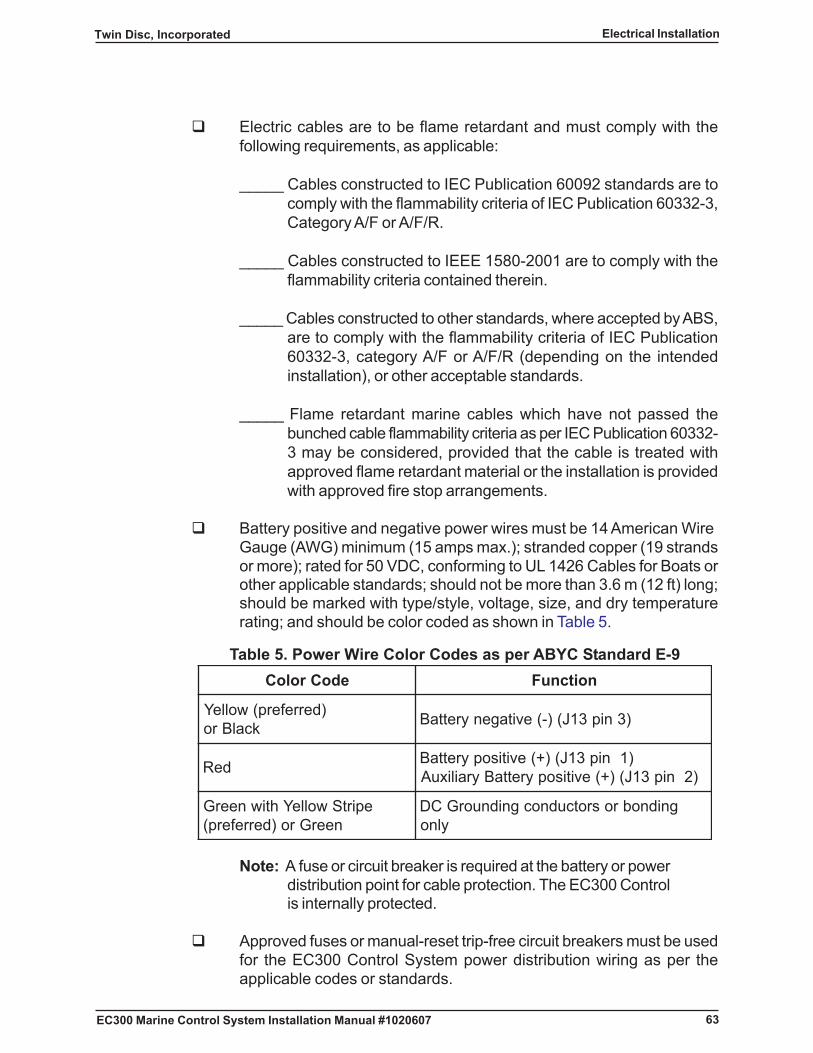
� Battery positive and negative power wires must be 14 American WireGauge (AWG) minimum (15 amps max.); stranded copper (19 strandsor more); rated for 50 VDC, conforming to UL 1426 Cables for Boats orother applicable standards; should not be more than 3.6 m (12 ft) long;should be marked with type/style, voltage, size, and dry temperaturerating; and should be color coded as shown in Table 5.
Table 5. Power Wire Color Codes as per ABYC Standard E-9edoCroloC noitcnuF
)derreferp(wolleYkcalBro )3nip31J()-(evitagenyrettaB
deR )1nip31J()+(evitisopyrettaB)2nip31J()+(evitisopyrettaByrailixuA
epirtSwolleYhtiwneerGneerGro)derreferp(
gnidnobrosrotcudnocgnidnuorGCDylno
Note: A fuse or circuit breaker is required at the battery or powerdistribution point for cable protection. The EC300 Controlis internally protected.
� Approved fuses or manual-reset trip-free circuit breakers must be usedfor the EC300 Control System power distribution wiring as per theapplicable codes or standards.
64
Twin Disc, IncorporatedElectrical Installation
EC300 Marine Control System Installation Manual #1020607
� A 15A fuse and fuse holder are supplied in the Power Connector Kit(J13).
� All fuses must meet the general provisions of Article 240 of the NationalElectrical Code or IEC 92-202, as appropriate, and have an interruptingrating sufficient to interrupt the maximum asymmetrical RMS short-circuitcurrent at the point of application. Each fuse must provide for readyaccess to test the condition of the fuse.
� Unless otherwise permitted, the fuse or circuit breaker must be locatedwithin 178 mm (7 in) of the point at which the power conductor isconnected. If the wire is continually sheathed or enclosed and ifconnected directly to a battery terminal, the distance may be up to 1,829mm (72 in). If connecting downstream of the battery terminal the circuitprotection must be within 1,016 mm (40 in) of the connection.
� Power distribution wiring must be insulated. Caps or boots are requiredat all terminals in order to prevent accidental shorts.
� Special requirements apply to vessels with gasoline, liquid petroleumgas (LPG), or Marine Compressed Natural Gas (CNG) engines or tovessels with hazardous areas. Power routing and wiring must meet allapplicable codes and standards. Circuit components may have to berated as Ignition Protected as per SAE J1171 External Ignition Protectionof Marine Electrical Devices, UL 1500 Ignition Protection Test to MarineProducts, and the electrical system requirements for boats in Title 33CFR 183.410(a).
� The main power wires to the power/interface connector (battery + andbattery -) must be routed directly to the battery or a primary distributionpanel within 1 m (3.3 ft) of the battery, but not the starter feed.
� Do not connect the EC300 Control’s battery + or - power input directlyto the engine or any of its electrical components.
� Connect the control power wires to the battery for the engine controlledby the EC300 Control. Port engine controls should be connected to the“port” battery. Starboard engine controls should be connected to the“starboard” battery.
� Use a good quality connector to connect the power wires to the batteryor bus bar and check the wires to be sure they are secure. Do not usesimple spring-loaded connectors.

65
Twin Disc, Incorporated Electrical Installation
EC300 Marine Control System Installation Manual #1020607
� DC Distribution must be a two-wire system. Battery return wiring mustbe routed to the battery and not to the bonding system or the metallichull. The negative side of the battery must be connected to ground if thesystem is to be grounded.
� The electrical load added by the EC300 Control System is not large.Current is limited to 15 amps at either 12 or 24 VDC. However, in somecircumstances, this may require an increase in the capacity of the powerdistribution system, larger batteries, and/or larger grounding conductors.The customer is responsible for meeting the applicable code andstandard requirements.
Neutral Start Interlock Wiring Requirements
All EC300 Control Systems include a Neutral Start Interlock feature for preventionof start-in-gear situations. The Neutral Start Interlock is a relay contact insideof the EC300 Control which is normally located in the engine room. The relaycontact only closes when the system ignition is turned on, a Control Head isselected, and the lever for the selected Control Head is placed in the neutralposition. Normally, the boat wiring routes the start command wire from the keyswitch or engine control panel through the EC300 Control’s Neutral StartInterlock. If a bypass or override switch is desired, contact Twin DiscIncorporated or a local distributor for information related to specific installationrequirements. Damage or injury that is caused by improper installation is notthe responsibility of Twin Disc Incorporated or its distributors.
The following criteria must be met when installing neutral start interlock wiring:
� These wires must be 14 AWG stranded copper.
� Neutral start interlock wiring must be connected to prevent the enginefrom starting with the gear selector out of the neutral position. If a hardwired transmission neutral switch is available, route the engine startsignal through the switch.
� Route the wire from the ignition switch to the starter relay through theinterlock contact connections provided via Engine Throttle Connector(J5).
� If more than 5 amps are required for the neutral start interlock circuit, atransfer relay must be installed using the diagram provided on the systeminstallation drawing.
66
Twin Disc, IncorporatedElectrical Installation
EC300 Marine Control System Installation Manual #1020607
Routing Requirements
The following criteria must be met when routing electrical wiring:
� Wiring must be the minimum practical length.
� Wire bend radii should be at least eight wire-diameters unless otherwisepermitted.
CAUTIONKeep the EC300 system wires away from antenna wires and AC powerwires. Do not route the EC300 control wires in the same trough orconduit as antenna or AC power wires.
� Wiring must be located away from high current conductors and devices.Wiring must be at least 1 m (3.3 ft) away from communicationsequipment, antennas and associated leads. Wiring must be at least 1m (3.3 ft) away from alternators, generators, and ignition systems.
� Wiring must be located away from hot surfaces or high-risk fire areas.
� Wiring must be clear of service areas, access areas, or other spaceswhere it may be exposed to mechanical damage. Where this cannotbe avoided, special measures are to be made for effective protectionof wiring.
� Wiring should have drip loops at each connection point as required tominimize water drainage toward the connector.
� Do not splice or substitute different types of wire into the harnesses.Increased length may require increased wire size.
� Any splices must meet the requirements of the applicable standards orspecifications.
� Wiring is to be secured in such a manner that stresses are not transmittedto the connector terminal.
� Wiring and harnesses must be supported or secured every 406 mm (16in) maximum with the appropriate hardware except if the wiring isenclosed in rigid duct, conduit, or other enclosure. The distance betweencable supports are to be suitably chosen according to the type of cable

67
Twin Disc, Incorporated Electrical Installation
EC300 Marine Control System Installation Manual #1020607
and the degree of vibration the installation is likely to be subjected to.For horizontal runs where cables are laid on tray plates, individual supportbrackets or hanger ladders, the distance between the fixing points maybe up to 914 mm (36 in), provided that there are supports with maximumspacing as specified above. Increased support will be required for cableruns on weather decks where forces from sea water washing over thedeck is expected. Alternatively, cable support systems complying with arecognized standard other than IEC 60092-352 may be used where theinstalled cables also comply with that standard. Specifically, cable supportsystems meeting the requirements of IEEE 1580-2001 may be usedwhere IEEE 1580-2001 cables are installed.
� Metallic cable clamps or supports are required if the failure of the supportcould cause a hazardous condition in the engine room, machinery rooms,or passageways.
� Clamps and supports shall not have sharp edges or rough surfaces thatcould damage the insulation. Special protective measures such as tapeor other wrapping are required for metallic clamps or supports. Clips,saddles, and straps are to have surface area sufficiently wide andshaped that the cables are fixed tight without their covering beingdamaged.
� Non-metallic clamps and supports must be resistant to oil, gasoline,and water and shall have a temperature range of -34 to 121°C (-30 to250°F). They shall be flame retardant in accordance with IEC Publication60092-101. Where used for cables that are not routed on top ofhorizontal cable trays, suitable metal clips or straps are to be added atregular intervals not exceeding 2 m (6.6 ft) in order to prevent the releaseof cables during a fire.
� Do not use wire staples, as staples can damage the insulation and allowthe conductor to break under stress.
� Where cables pass through watertight or fire-rated bulkheads or decks,the penetrations are to be made through the use of approved stuffingtubes, transit devices, or pourable materials in order to maintain thewatertight or firetight integrity of the bulkheads or decks. These devicesor materials must not damage the cable. Where cable conduit pipe orequivalent is carried through decks or bulkheads, arrangements are tobe made to maintain the integrity of the water or gas tightness of thestructure.
68
Twin Disc, IncorporatedElectrical Installation
EC300 Marine Control System Installation Manual #1020607
� Cables are not to be installed behind, or imbedded in, structuralinsulation. They may, however, pass through such insulation at rightangles. Cable conduit or recesses integral with B or C class fire-wallsmay be used for installing cables if the fire-walls are of an approvedtype and the installation prevents the propagation of smoke through theconduit.
� When cables pass through non-watertight bulkheads, decks or structuralmembers, the length of the bearing surface for the cable is to be at least6.4 mm (0.25 in). All burrs and sharp edges are to be removed.
� No cable is allowed to penetrate the collision bulkhead.
� The rated temperature of the cable’s insulating material is to be at least10°C (18°F) higher than the maximum ambient temperature likely to bein the space where the cable is installed.
� To avoid possible signal interference, signal cables occupying the samewireway or conduit with power cables are to be effectively shielded.
Bonding Requirements
The EC300 Control must be bonded. If used, the Station Doubler and the ServoActuator must also be bonded.
Note: Insulated push-pull cable mounting hardware may benecessary to satisfy bond/isolation requirements,especially if the engine block is not grounded to the batterynegative. See Push-Pull Cable Installation Kits forNonconductive Vessels.
The following criteria must be met when making bonding connections:
� The EC300 Control must be directly bonded to battery negative, bondrails, or hull plates. If the engine is grounded to the battery negativeterminal, then the EC300 Control’s bond connection should also be tothe battery negative. If the vessel or engine has an independent bondingsystem, then the control should be bonded to the independent bondingsystem.
69
Twin Disc, Incorporated Electrical Installation
EC300 Marine Control System Installation Manual #1020607
� Bond wires must be connected to one of the unpainted mounting surfacesof the EC300 Control, the Station Doubler, and/or the Servo Actuator.Any paint must be removed in order to make the bonding connection.The bond wire must be terminated with a ring lug that fits the fastenerused to mount the component.
� The bonding conductor must be 14 AWG stranded copper wire withinsulation that is colored green with yellow stripe (preferred) or green.
Wiring Connections
The following criteria must be met when making wiring connections:
� All electrical connections must be made within waterproof enclosuresor shall be watertight. Connections must be watertight if they can beimmersed in water.
� Wiring connections must not damage the conductor.
� Metals used for connections shall be corrosion resistant.
� Terminal lugs shall be ring lug or captive spade styles and shall be sizedto match the terminal and the conductor. Shanks shall be insulated unlessused on a grounded conductor. Crimp lugs must be of equal or greatercurrent rating than the wire.
� Cables stripped of insulation are to be sealed using heat shrink tubingin combination with insulating compound or sealing devices.
� Crimps must be made with a tool designed to operate with the lug/contact. Crimps shall be able to hold 13.6 kg (30 lb) for one minute.
� Aluminum or unplated steel shall not be used for fasteners.
� Twist-on connectors, such as wire nuts, shall not be used.
� Solder may not be the only means of connection between two or moreconductors or between a conductor and a connector.

70
Twin Disc, IncorporatedElectrical Installation
EC300 Marine Control System Installation Manual #1020607
� Any friction connectors or soldered connectors at components must meetthe component manufacturer’s requirements as well as the applicablestandards.
� No more than four conductors may be terminated at any single stud.
� Wires shall have sufficient freedom of movement to allow for removal,dressing, and tension relief.
� To avoid electromagnetic noise caused by circulating currents, theconductive shield and cable armor of signal cables is to be groundedonly at one end of the cable.
71
Twin Disc, Incorporated Electrical Installation
EC300 Marine Control System Installation Manual #1020607
Control Head Harness (J1, J2, or J3) Installation
This section contains the following sub-sections:
� Control Head Harness Routing Guidelines
� Multi-Station Single Lever Control Head Wiring Installation
� Multi-Station Dual Lever Control Head Wiring Installation
� Multi-Station Dual Lever Control Head Wiring Installation Using StationDoublers
� Split Single Lever Control Heads in Twin Engine Installations WithoutStation Doublers
� Control Head Wiring for Master Switch Applications Without StationDoublers
� Control Head Wiring for Phantom Switch Applications Without StationDoublers
Control Head Harness Routing Guidelines
Follow these guidelines when routing the Control Head harnesses:
� Keep clear of service and access areas.
� Avoid hot surfaces.
� Avoid AC power and high current conductors.
� Avoid potential pinch or abrasion points.
� Use vertical or overhead surfaces for attachment if possible.
� Do not route across deck.
� Ensure that harnesses can be properly supported along their length.
� Arrange harnesses so that drip-loops are formed.
� Route harnesses at least 1 m (3.3 ft) away from communicationsequipment and associated leads.
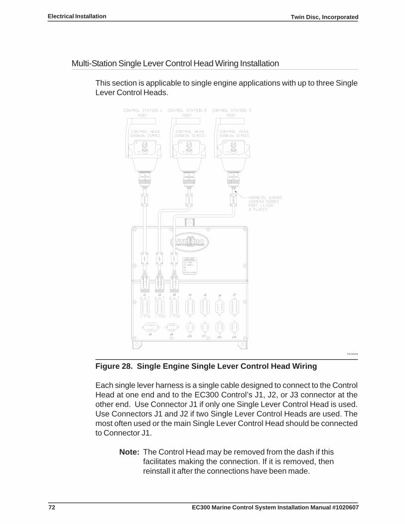
72
Twin Disc, IncorporatedElectrical Installation
EC300 Marine Control System Installation Manual #1020607
Multi-Station Single Lever Control Head Wiring Installation
This section is applicable to single engine applications with up to three SingleLever Control Heads.
TD10028
Figure 28. Single Engine Single Lever Control Head Wiring
Each single lever harness is a single cable designed to connect to the ControlHead at one end and to the EC300 Control’s J1, J2, or J3 connector at theother end. Use Connector J1 if only one Single Lever Control Head is used.Use Connectors J1 and J2 if two Single Lever Control Heads are used. Themost often used or the main Single Lever Control Head should be connectedto Connector J1.
Note: The Control Head may be removed from the dash if thisfacilitates making the connection. If it is removed, thenreinstall it after the connections have been made.

73
Twin Disc, Incorporated Electrical Installation
EC300 Marine Control System Installation Manual #1020607
Note: The Control Head may be removed from the dash if thisfacilitates making the connection. If it is removed, thenreinstall it after the connections have been made.
Note: Provide enough length in the harness to allow removal ofthe Control Head in the future.
Note: For each Control Head connector, align the large connectorkey with the large keyway and push the connector intoplace. Then, turn the connector’s collar until engagementsnap is felt.
1. Connect the circular connector end of the Control Head harness to theControl Station 1 Single Lever Control Head.
2. Ensure that the Single Lever Control Head is firmly mounted.
3. Route the Control Head harness to the EC300 Control.
4. Connect the Control Head Harness’s plug at the J1 receptacle of theEC300 Control.
5. If applicable, repeat Steps 1 through 4 for connecting the Control Station2 Single Lever Control Head at the J2 receptacle of each EC300 Control.
6. If applicable, repeat Steps 1 through 4 for connecting the Control Station3 Single Lever Control Head at the J3 receptacle of each EC300 Control.
7. Secure all harnesses to a supporting structure with clamps or cable tiesat 406 mm (16 in) intervals. See Routing Requirements.
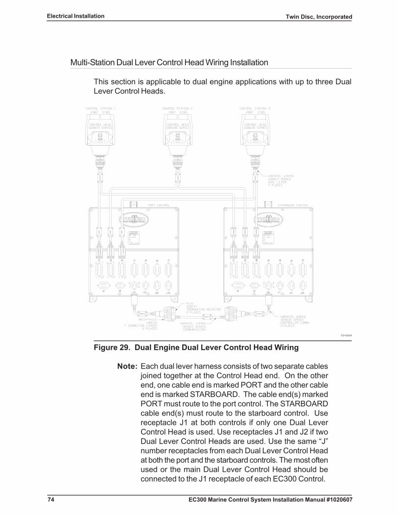
74
Twin Disc, IncorporatedElectrical Installation
EC300 Marine Control System Installation Manual #1020607
Multi-Station Dual Lever Control Head Wiring Installation
This section is applicable to dual engine applications with up to three DualLever Control Heads.
TD10029
Figure 29. Dual Engine Dual Lever Control Head Wiring
Note: Each dual lever harness consists of two separate cablesjoined together at the Control Head end. On the otherend, one cable end is marked PORT and the other cableend is marked STARBOARD. The cable end(s) markedPORT must route to the port control. The STARBOARDcable end(s) must route to the starboard control. Usereceptacle J1 at both controls if only one Dual LeverControl Head is used. Use receptacles J1 and J2 if twoDual Lever Control Heads are used. Use the same “J”number receptacles from each Dual Lever Control Headat both the port and the starboard controls. The most oftenused or the main Dual Lever Control Head should beconnected to the J1 receptacle of each EC300 Control.
75
Twin Disc, Incorporated Electrical Installation
EC300 Marine Control System Installation Manual #1020607
Note: The Control Head may be removed from the dash if thisfacilitates making the connection. If it is removed, thenreinstall it after the connections have been made.
Note: Provide enough length in the harness to allow removal ofthe Control Head in the future.
Note: For each Control Head connector, align the large connectorkey with the large keyway and push the connector intoplace. Then, turn the connector’s collar until engagementsnap is felt.
1. Connect the circular connector end of the dual lever harness to theControl Station 1 Dual Lever Control Head.
2. Ensure that the Dual Lever Control Head is firmly mounted.
3. Route the cable marked “PORT” to the EC300 Port Control.
4. Plug the “PORT” cable into the J1 receptacle of the EC300 Port Control.
5. Route the cable marked “STARBOARD” to the EC300 StarboardControl.
6. Plug the “STARBOARD” cable into the J1 receptacle of the EC300Starboard Control.
7. If applicable, repeat steps 1 through 6 for connecting the Control Station2 Dual Lever Control Head to the J2 receptacle of each EC300 Control.
8. If applicable, repeat steps 1 through 6 for connecting the Control Station3 Dual Lever Control Head to the J3 receptacle of each EC300 Control.
9. Secure all harnesses to a supporting structure with clamps or cable tiesat 406 mm (16 in) intervals. See Routing Requirements.
Note: The EC300 Control’s communication harness assemblyis shown in the Communication Harness (J10) Installationsection of this manual.

76
Twin Disc, IncorporatedElectrical Installation
EC300 Marine Control System Installation Manual #1020607
Multi-Station Dual Lever Control Head Wiring Installation Using Station Doublers
This section is applicable to multiple engine applications with more than three(3) Dual Lever Control Heads per EC300 Control. Up to six Control Heads canbe used through the use of Station Doublers. Each Station Doubler combinesthe signals from two separate Control Heads and routes the combined signalsto each of the EC300 Controls (J1, J2, or J3).
Note: Station Doublers may also be used on single-engineSingle Lever Control Head applications if more than threeControl Heads are required. Single Lever Control Headstation-to-doubler harnesses are used in place of the duallever station-to-doubler harnesses. A port station-to-doubler harness is used with a Port Control Head. Astarboard station-to-doubler harness is used with aStarboard Control Head.
TD10055
Figure 30. Station Doubler Connection Using Dual Lever Control Heads

77
Twin Disc, Incorporated Electrical Installation
EC300 Marine Control System Installation Manual #1020607
Note: The Station Doubler Harnesses route between the ControlHeads and the Station receptacles on the Station Doubler.The Dual Lever Harness routes between the CONTROLconnector on the Station Doubler and the EC300 Control.
Note: The Control Head may be removed from the dash if thisfacilitates making the connection. If it is removed, thenreinstall it after the connections have been made.
Note: Provide enough length in the harness to allow removal ofthe Control Head in the future.
Note: For each Control Head connector, align the large connectorkey with the large keyway and push the connector intoplace. Then, turn the connector’s collar until engagementsnap is felt.
1. Connect the circular connector end of a station-to-doubler harness tothe Control Station 1 Dual Lever Control Head.
2. Ensure that the Control Station 1 Dual Lever Control Head is firmlymounted.
3. Route the Control Station 1 station-to-doubler harness to the StationDoubler.
4. Plug the cable marked “PORT” into the receptacle marked “STATIONA” on the side of the Station Doubler marked “PORT”.
5. Plug the cable marked “STARBOARD” into the receptacle marked“STATION A” on the side of the Station Doubler marked “STBD”.
6. Connect the circular connector end of a station-to-doubler harness tothe Control Station 2 Dual Lever Control Head.
7. Ensure that the Control Station 2 Dual Lever Control Head is firmlymounted.
8. Route the Control Station 2 station-to-doubler harness to the StationDoubler.
9. Plug the cable marked “PORT” into the receptacle marked “STATIONB” on the side of the Station Doubler marked “PORT”.

78
Twin Disc, IncorporatedElectrical Installation
EC300 Marine Control System Installation Manual #1020607
10. Plug the cable marked “STARBOARD” into the receptacle marked“STATION B” on the side of the Station Doubler marked “STBD”.
11. Connect the circular connector end of a Dual Lever Control Head harnessto the receptacle on the Station Doubler marked “CONTROL”.
12. Route the cable marked “PORT” to the EC300 Port Control.
13. Plug the “PORT” cable into the J1 receptacle of the EC300 Port Control.
14. Route the cable marked “STARBOARD” to the EC300 StarboardControl.
15. Plug the “STARBOARD” cable into the J1 receptacle of the EC300Starboard Control.
16. If applicable, repeat steps 1 through 15 to connect Station 3 and 4 DualLever Control Heads through a second Station Doubler to the J2receptacles of the EC300 Port and Starboard Controls.
17. If applicable, repeat steps 1 through 15 to connect Station 5 and 6 DualLever Control Heads through a third Station Doubler to the J3 receptacleof the EC300 Port and Starboard Controls.
18. Secure all harnesses to a supporting structure with clamps or cable tiesat 406 mm (16 in) intervals. See Routing Requirements.
Note: The bonding conductor must be 14 AWG stranded copperwire. It must be colored green with a yellow stripe(preferred) or green in order to comply with ABYCstandards.
19. Route a bond wire from the vessel bonding system to the selectedmounting pad on each Station Doubler. See Figure 30.
Note: The ring lug must be properly sized for both the wire andthe mounting fastener.
20. Install a ring lug on the control end of the wire.
21. Remove the mounting fastener at the bonding connection.
22. Remove any paint at the mounting connection in order to ensure electricalcontact.
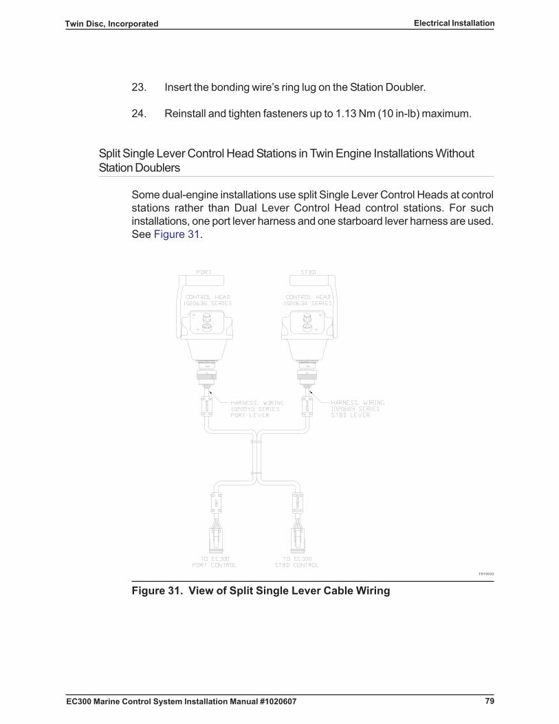
79
Twin Disc, Incorporated Electrical Installation
EC300 Marine Control System Installation Manual #1020607
23. Insert the bonding wire’s ring lug on the Station Doubler.
24. Reinstall and tighten fasteners up to 1.13 Nm (10 in-lb) maximum.
Split Single Lever Control Head Stations in Twin Engine Installations WithoutStation Doublers
Some dual-engine installations use split Single Lever Control Heads at controlstations rather than Dual Lever Control Head control stations. For suchinstallations, one port lever harness and one starboard lever harness are used.See Figure 31.
TD10032
Figure 31. View of Split Single Lever Cable Wiring

80
Twin Disc, IncorporatedElectrical Installation
EC300 Marine Control System Installation Manual #1020607
Install the Control Head harnesses as follows:
Note: The Control Head may be removed from the dash if thisfacilitates making the connection. If it is removed, thenreinstall it after the connections have been made.
Note: Provide enough length in the harness to allow removal ofthe Control Head in the future.
Note: For each Control Head connector, align the large connectorkey with the large keyway and push the connector intoplace. Then, turn the connector’s collar until engagementsnap is felt.
1. Connect the circular connector end of the port lever harness to the portControl Head.
2. Connect the circular connector end of the starboard harness to thestarboard Control Head.
3. Ensure that the port and starboard single lever Control Heads are firmlymounted.
4. Route the port lever harness to the EC300 port Control.
5. Connect the port lever harness at the EC300 port Control (J1).
6. Route the starboard lever harness to the EC300 starboard Control.
7. Connect the starboard lever harness at the EC300 starboard ControlConnector (J1).
8. If applicable, repeat Steps 1 through 6 for connecting the Control Station2 split Single Lever Control Heads at each EC300 Control (J2).
9. If applicable, repeat Steps 1 through 6 for connecting the Control Station3 Single Lever Control Heads at each EC300 Control (J3).
10. Secure all harnesses to a supporting structure with clamps or cable tiesat 406 mm (16 in) intervals. See Routing Requirements.
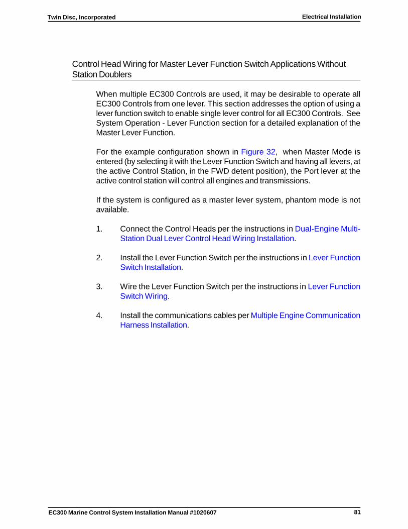
81
Twin Disc, Incorporated Electrical Installation
EC300 Marine Control System Installation Manual #1020607
Control Head Wiring for Master Lever Function Switch Applications WithoutStation Doublers
When multiple EC300 Controls are used, it may be desirable to operate allEC300 Controls from one lever. This section addresses the option of using alever function switch to enable single lever control for all EC300 Controls. SeeSystem Operation - Lever Function section for a detailed explanation of theMaster Lever Function.
For the example configuration shown in Figure 32, when Master Mode isentered (by selecting it with the Lever Function Switch and having all levers, atthe active Control Station, in the FWD detent position), the Port lever at theactive control station will control all engines and transmissions.
If the system is configured as a master lever system, phantom mode is notavailable.
1. Connect the Control Heads per the instructions in Dual-Engine Multi-Station Dual Lever Control Head Wiring Installation.
2. Install the Lever Function Switch per the instructions in Lever FunctionSwitch Installation.
3. Wire the Lever Function Switch per the instructions in Lever FunctionSwitch Wiring.
4. Install the communications cables per Multiple Engine CommunicationHarness Installation.
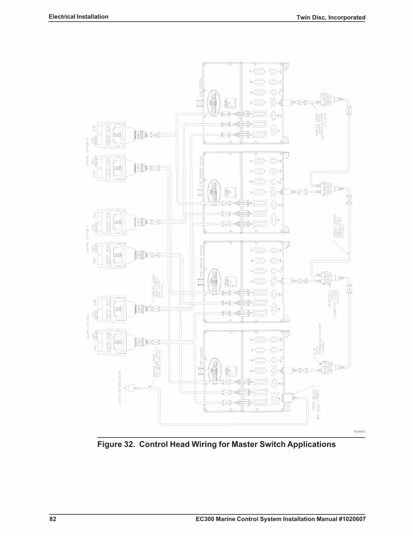
82
Twin Disc, IncorporatedElectrical Installation
EC300 Marine Control System Installation Manual #1020607
TD10033
Figure 32. Control Head Wiring for Master Switch Applications

83
Twin Disc, Incorporated Electrical Installation
EC300 Marine Control System Installation Manual #1020607
Control Head Wiring for Phantom Lever Function Switch Applications WithoutStation Doublers
When multiple EC300 Controls are used, it may be desirable to operate multipleengines/transmissions from one lever. This section addresses the option ofusing a Lever Function Switch to enable Phantom Mode Control. See SystemOperation - Lever Function section for a detailed explanation of the PhantomLever Function.
For the example configuration shown in Figure 33, when Phantom Mode isentered (by selecting it with the Lever Function Switch and having all levers, atControl Station 1, in the NEUT detent position), the Port lever at Control Station1 will control the Port and Center engines and transmissions.
TD10034
Figure 33. Control Head Wiring for Phantom Switch Applications

84
Twin Disc, IncorporatedElectrical Installation
EC300 Marine Control System Installation Manual #1020607
If the system is configured as a phantom mode lever system, master lever modeis not available.
1. Connect the Control Heads per the instructions in the appropriate ControlHead Wiring Installation sections.
2. Install the Lever Function Switch per the instructions in Lever FunctionSwitch Installation.
3. Wire the Lever Function Switch per the instructions in Lever FunctionSwitch Wiring.
4. Install the communications cables per the Multiple EngineCommunication Harness Installation.
Multiple Lever Station Wiring Using Station Doublers
A maximum of six Control Heads can be used on an EC300 Control Systeminstallation. Each EC300 Control can directly accept up to three Control Headinputs. Using Station Doublers, a total of six Control Head inputs can besupported.
Figure 34 shows five Control Heads and two Station Doublers. Using a thirdStation Doubler, a sixth Control Head can be combined with the inputs from themain or navigation bridge control station. The main or navigation bridge ControlHead wiring should not be combined through the use of a Station Doubler unlessnecessary to obtain the maximum number of stations.
1. Refer to the interconnection diagram supplied with your order.
2. Perform the necessary wiring harness installations as outlined in theapplicable component instructions.
3. Install the communications harness per the Dual Engine CommunicationHarness Installation.
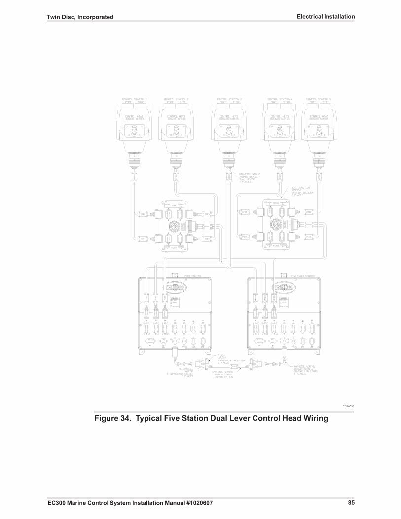
85
Twin Disc, Incorporated Electrical Installation
EC300 Marine Control System Installation Manual #1020607
TD10035
Figure 34. Typical Five Station Dual Lever Control Head Wiring
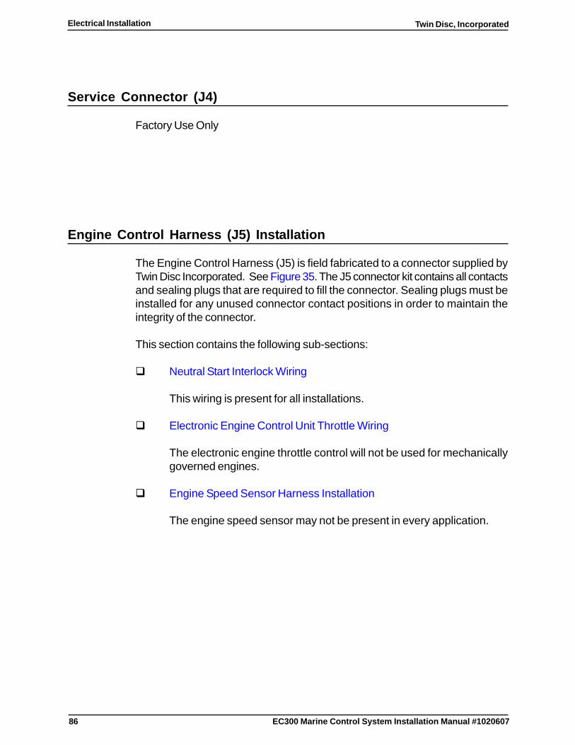
86
Twin Disc, IncorporatedElectrical Installation
EC300 Marine Control System Installation Manual #1020607
Service Connector (J4)
Factory Use Only
Engine Control Harness (J5) Installation
The Engine Control Harness (J5) is field fabricated to a connector supplied byTwin Disc Incorporated. See Figure 35. The J5 connector kit contains all contactsand sealing plugs that are required to fill the connector. Sealing plugs must beinstalled for any unused connector contact positions in order to maintain theintegrity of the connector.
This section contains the following sub-sections:
� Neutral Start Interlock Wiring
This wiring is present for all installations.
� Electronic Engine Control Unit Throttle Wiring
The electronic engine throttle control will not be used for mechanicallygoverned engines.
� Engine Speed Sensor Harness Installation
The engine speed sensor may not be present in every application.
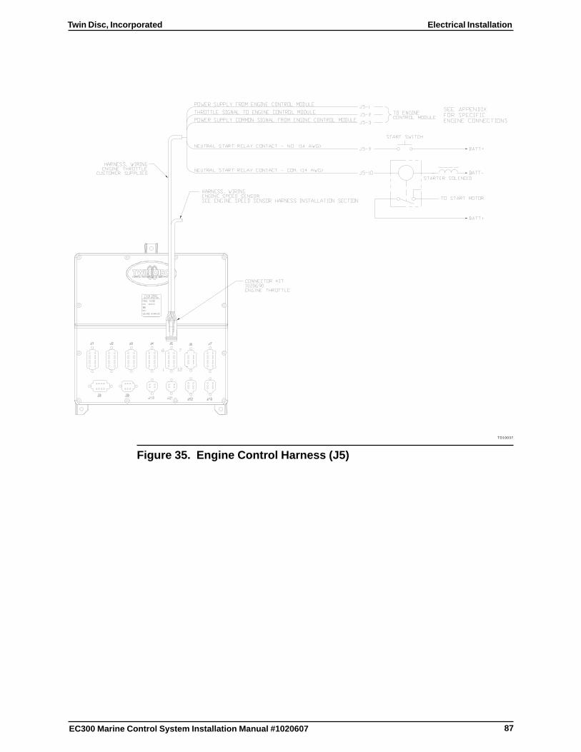
87
Twin Disc, Incorporated Electrical Installation
EC300 Marine Control System Installation Manual #1020607
TD10037
Figure 35. Engine Control Harness (J5)
88
Twin Disc, IncorporatedElectrical Installation
EC300 Marine Control System Installation Manual #1020607
Neutral Start Interlock Wiring
The EC300 Control is designed to ensure that a control station is in commandand that the Control Head is in the neutral detent position before an engine canbe started. Thus, the output of the start or ignition switch is routed to the startersolenoid through the EC300 Control.
CAUTIONBypassing of the neutral start interlock may cause damage or injury.Twin Disc Incorporated and its distributors are not responsible for theresults of any improper wiring. Contact Twin Disc Incorporated or alocal distributor for recommendations related to any engine-room startswitch.
Two pins are provided in the control’s Engine throttle connector kit (J5) forneutral start interlock wiring. Connector J5 pin 9 and conector J5 pin 10 are foruse with commonly available DC engine system voltages (12/24 VDC Nominal).See Figure 36. The neutral interlock contact rating is 5 amps DC maximum.The hook up wire must be 14 AWG stranded copper wire.
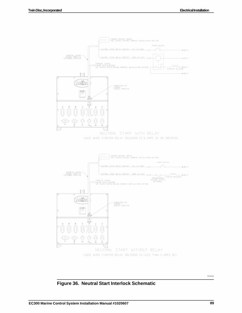
89
Twin Disc, Incorporated Electrical Installation
EC300 Marine Control System Installation Manual #1020607
TD10039
Figure 36. Neutral Start Interlock Schematic
90
Twin Disc, IncorporatedElectrical Installation
EC300 Marine Control System Installation Manual #1020607
A Neutral Start Interlock Relay must be used for isolation if the starter relay/solenoid current exceeds 5 amps DC. Use an isolation relay if the startersolenoid/relay current is unknown or if no means to measure the current isavailable.
Note: The EC300 Control’s neutral start interlock contacts andany hardwired transmission neutral interlock must be wiredin series with the vessel’s starting circuit. If a hardwiredtransmission neutral start switch is present, then modifythe following installation procedures to accommodate theswitch. Both interlock contacts must be in series from thepositive battery connection.
The exact nature of the customer wiring will depend upon whether or not a relayis required. It will also depend upon the nature of the customer’s existing wiring.The following steps assume that the Ignition Switch (start switch) Contact, theStarter Solenoid, and the Neutral Start Relay (if used) are already installed.
1. If a wire is present between the existing Ignition Switch Contact and theStarter Solenoid or Customer Relay, then remove it.
Note: It may be desirable to complete any other terminationsfor this harness before securing the harness.
2. Connect the first yellow with a red stripe wire to the load side of theIgnition Switch Contact.
3. Connect the second yellow with a red stripe wire to the starter solenoidcircuit as follows:
� Connect to the Starter Solenoid coil if no relay or TransmissionNeutral Switch is required.
� Connect to the relay coil if a relay is required.
� Connect to the hardwired Transmission Neutral Switch, if one isprovided.

91
Twin Disc, Incorporated Electrical Installation
EC300 Marine Control System Installation Manual #1020607
4. Route both yellow with a red stripe wires to the EC300 Control.
Note: The Deutsch 14 AWG contact (P/N 0462-209-16141) canbe identified by a green band.
5. For the first yellow with a red stripe wire from the start switch, crimp thesupplied Deutsch contact (P/N 0462-209-16141) using the Deutsch HDTcrimp tool (P/N 48-00).
6. Remove the locking wedge (P/N W12S-P012) from the Deutschconnector.
Note: Refer to the EC300 Dimensional Drawing in EngineeringDrawings for pin numbering information.
Note: The J5 connector is provided in the Engine throttleconnector kit.
7. Insert the first wire into position 9 of the J5 connector.
8. For the second yellow with a red stripe wire from the starter solenoidcircuit, crimp the supplied contact (Deutsch P/N 0462-209-16141) usingthe Deutsch crimp tool (P/N HDT 48-00).
9. Insert the second wire into position 10 of the J5 connector.
10. When all pins have been inserted in the connector body, then reinsertthe locking wedge (Deutsch P/N W12S-P012).
11. Ensure that sealing plugs are installed in all empty connector positions.
12. Align the harness connector with the J5 receptacle of the EC300 Controland push it in until it snaps into place.
13. Secure all harnesses to a supporting structure with clamps or cable tiesat 406 mm (16 in) intervals. See Routing Requirements.
92
Twin Disc, IncorporatedElectrical Installation
EC300 Marine Control System Installation Manual #1020607
Electronic Engine Control Unit Throttle Wiring
If the specific engine is not listed, contact Twin Disc Incorporated or a localdistributor for custom information and support.
Note: All EC300 Control configuration, with respect to theengine, is performed by Twin Disc Incorporated or itslocal distributor.
The EC300 Control System currently supports the following types of electronicengine controls:
� Caterpillar
� Cummins Centry
� Cummins Quantum Voltage Type
� Detroit Diesel Voltage
� Deutz Type 1
� Deutz Type 2
� John Deere
� MAN Current
� MTU
� Scania
� Volvo Penta
Refer to the Appendix for detailed electrical installation requirements for theengines listed.

93
Twin Disc, Incorporated Electrical Installation
EC300 Marine Control System Installation Manual #1020607
The next section provides general information about engine control wiring. Then,general instructions are provided for the fabrication and wiring of the engineharness for the engine controls.
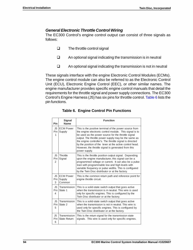
94
Twin Disc, IncorporatedElectrical Installation
EC300 Marine Control System Installation Manual #1020607
General Electronic Throttle Control WiringThe EC300 Control’s engine control output can consist of three signals asfollows:
� The throttle control signal
� An optional signal indicating the transmission is in neutral
� An optional signal indicating the transmission is not in neutral
These signals interface with the engine Electronic Control Modules (ECMs).The engine control module can also be referred to as the Electronic ControlUnit (ECU), Electronic Engine Control (EEC), or other similar names. Theengine manufacturer provides specific engine control manuals that detail therequirements for the throttle signal and power supply connections. The EC300Control’s Engine Harness (J5) has six pins for throttle control. Table 6 lists thepin functions.
Table 6. Engine Control Pin Functions
niPlangiS
emaNnoitcnuF
5JniP
1
rewoPMCEylppuS
morfecruosrewopehtfolanimretevitisopehtsisihTotsilangissihT.eludomlortnoccinortceleenigneeht
langiselttorhtehtrofecruosrewopehtsadesuebsaemasehtebyamylppusrewopelttorhtehT.tuptuo
detceridsilangiselttorhtehT.s'rellortnocenigneeht.daehlortnocevitcaehttarevelehtfonoitisopehtyb
sihtmorfdetarenegsilangiselttorhteht,revewoH.ylppusrewop
5JniP
2
elttorhTlangiS
gnidnepeD.langistuptuonoitisopelttorhtehtsisihTaebnaclangissiht,rerutcafunamenigneehtnopu
eslupaeboslanactI.tnerrucroegatlovdemmargorphtiwslevelhgihdnawolelbammargorphtiwniart
derugifnocsisihT.shtdiwesluproycneuqerfelbairav.yrotcafehttarorotubirtsidcsiDniwTehtyb
5JniP
3
rewoPMCEylppuS
nommoC
roftniopecnereferdnahtapnruternommocehtsisihT.tiucricelttorhtenigne
5JniP
4
noissimsnarT1etatS
evitcaseogtahttuptuohctiwsetats-dilosasisihTdesusieriwsihT.lartuennisinoissimsnartehtnehw
ehtybderugifnocsisihT.senignecificepsrofylno.yrotcafehttarorotubirtsidcsiDniwT
5JniP
5
noissimsnarT2etatS
evitcaseogtahttuptuohctiwsetats-dilosasisihTsieriwsihT.lartuennitonsinoissimsnartehtnehwybderugifnocsisihT.senignecificepsrofylnodesu
.yrotcafehttarorotubirtsidcsiDniwTeht
5JniP
6
noissimsnarTnruteRetatS
etatsnoissimsnartehtroflangisnruterehtsisihT.senignecificepsrofylnodesusieriwsihT.slangis

95
Twin Disc, Incorporated Electrical Installation
EC300 Marine Control System Installation Manual #1020607
Harness Fabrication and Wiring Procedure
Note: The connector kit supplied for Engine Harness J5 hasenough contacts and plugs necessary to fill the connector.Use only the contacts that are needed. Unused connectorpositions must have a sealing plug inserted in order tomaintain the environmental integrity of the connector.
1. Identify the wiring requirements for the specific engine from the appendix.
2. Locate the necessary connecting points on the engine control moduleor engine control wiring circuits.
Note: The Engine Harness connector at the J5 receptacle ofthe EC300 Control also includes neutral start interlockwiring and may include speed sensor wiring.
Note: The neutral start interlock wires (J5 pin 9 and J5 pin 10)must be 14 AWG stranded copper wire. All other wiresmust be a minimum of 18 AWG stranded copper wire.
3. Make a suitable interface cable containing the necessary conductors.
4. Connect the engine harness cable at the engine end.
5. Route the engine harness to the associated EC300 Control.
6. Crimp the contacts for the Engine Harness J5 connector on the wires.
7. Insert the wires into the connector. See Figure 37.
Note: Ensure that the crimp is uniform and complete. Ensurethat the wires are fully inserted in the connector.
Figure 37. Connector J5 Pin Layout from the Front

96
Twin Disc, IncorporatedElectrical Installation
EC300 Marine Control System Installation Manual #1020607
8. Ensure that sealing plugs are inserted in all unused connector positions.
9. When all pins have been inserted in the connector body, then insert theDeutsch locking wedge (P/N W12S-P012).
10. Align the harness connector with the J5 receptacle of the EC300 Controland push it in until it snaps into place.
11. Secure all harnesses to a supporting structure with clamps or cable tiesat 406 mm (16 in) intervals. See Routing Requirements.
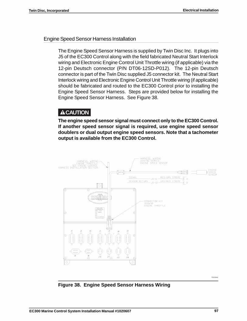
97
Twin Disc, Incorporated Electrical Installation
EC300 Marine Control System Installation Manual #1020607
Engine Speed Sensor Harness Installation
The Engine Speed Sensor Harness is supplied by Twin Disc Inc. It plugs intoJ5 of the EC300 Control along with the field fabricated Neutral Start Interlockwiring and Electronic Engine Control Unit Throttle wiring (if applicable) via the12-pin Deutsch connector (P/N DT06-12SD-P012). The 12-pin Deutschconnector is part of the Twin Disc supplied J5 connector kit. The Neutral StartInterlock wiring and Electronic Engine Control Unit Throttle wiring (if applicable)should be fabricated and routed to the EC300 Control prior to installing theEngine Speed Sensor Harness. Steps are provided below for installing theEngine Speed Sensor Harness. See Figure 38.
CAUTIONThe engine speed sensor signal must connect only to the EC300 Control.If another speed sensor signal is required, use engine speed sensordoublers or dual output engine speed sensors. Note that a tachometeroutput is available from the EC300 Control.
TD10041
Figure 38. Engine Speed Sensor Harness Wiring

98
Twin Disc, IncorporatedElectrical Installation
EC300 Marine Control System Installation Manual #1020607
1. Plug the 2-pin connector of the Engine Speed Sensor Harness into theEngine Speed Sensor receptacle.
Note: It may be desirable to complete any other terminationsfor this harness before securing the harness.
2. Route the Engine Speed Sensor Harness to the EC300 Control.
3. Plug the red with a green stripe wire into position 11 of the J5 Connector(locking wedge must be removed from plug prior to inserting wires toproperly seat the contact sockets).
4. Plug the green with a red stripe wire into position 12 of the J5 Connector.
Note: Refer to the EC300 Dimensional Drawing in EngineeringDrawings for pin numbering information.
5. Reinstall the locking wedge.
6. Install the 12-pin connector into the J5 receptacle of the EC300 Control.
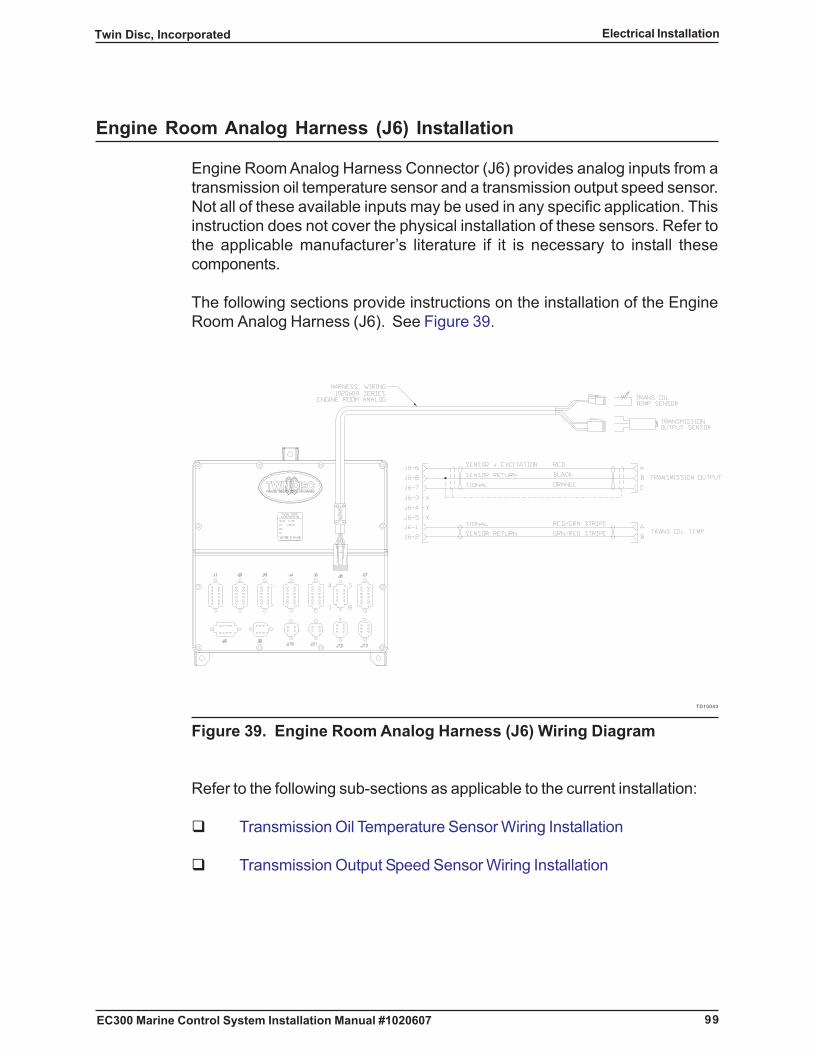
99
Twin Disc, Incorporated Electrical Installation
EC300 Marine Control System Installation Manual #1020607
Engine Room Analog Harness (J6) Installation
Engine Room Analog Harness Connector (J6) provides analog inputs from atransmission oil temperature sensor and a transmission output speed sensor.Not all of these available inputs may be used in any specific application. Thisinstruction does not cover the physical installation of these sensors. Refer tothe applicable manufacturer’s literature if it is necessary to install thesecomponents.
The following sections provide instructions on the installation of the EngineRoom Analog Harness (J6). See Figure 39.
TD10043
Figure 39. Engine Room Analog Harness (J6) Wiring Diagram
Refer to the following sub-sections as applicable to the current installation:
� Transmission Oil Temperature Sensor Wiring Installation
� Transmission Output Speed Sensor Wiring Installation

100
Twin Disc, IncorporatedElectrical Installation
EC300 Marine Control System Installation Manual #1020607
Transmission Oil Temperature Sensor Wiring Installation
Note: The Transmission Oil Temperature Sensor cable is partof the Engine Room Analog harness. Cable ties may beremoved for routing purposes.
Install the wiring connections for a Transmission Oil Temperature Sensor asfollows:
1. If required, connect the Engine Room Analog Harness at the J6receptacle of the EC300 Control.
2. If required, route the Engine Room Analog Harness to the associatedtransmission.
3. Install the Transmission Oil Temperature Sensor cable’s receptacle ontothe transmission oil temperature sensor’s plug.
Note: It may be desirable to complete any other terminationsfor this harness before securing the harness.
4. Secure all harnesses to a supporting structure with clamps or cable tiesat 406 mm (16 in) intervals. See Routing Requirements.
101
Twin Disc, Incorporated Electrical Installation
EC300 Marine Control System Installation Manual #1020607
Transmission Output Speed Sensor Wiring Installation
Install the wiring connections for a Transmission Output Speed Sensor asfollows:
Note: The Transmission Output Speed Sensor cable is part ofthe Engine Room Analog harness. Cable ties may beremoved for routing purposes.
1. If required, connect the Engine Room Analog Harness at the J6receptacle of the EC300 Control.
2. If required, route the Engine Room Analog Harness to the associatedtransmission.
3. Install the Transmission Output Speed Sensor cable’s plug into theTransmission Output Speed Sensor’s receptacle.
4. Secure all harnesses to a supporting structure with clamps or cable tiesat 406 mm (16 in) intervals. See Routing Requirements.
Tooth Count
Note: The EC300 Control must be configured with the correcttooth count. Obtain the correct tooth count informationfrom the manufacturer’s literature or count the teeth.
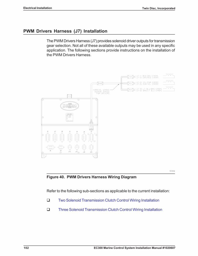
102
Twin Disc, IncorporatedElectrical Installation
EC300 Marine Control System Installation Manual #1020607
PWM Drivers Harness (J7) Installation
The PWM Drivers Harness (J7) provides solenoid driver outputs for transmissiongear selection. Not all of these available outputs may be used in any specificapplication. The following sections provide instructions on the installation ofthe PWM Drivers Harness.
TD10042
Figure 40. PWM Drivers Harness Wiring Diagram
Refer to the following sub-sections as applicable to the current installation:
� Two Solenoid Transmission Clutch Control Wiring Installation
� Three Solenoid Transmission Clutch Control Wiring Installation

103
Twin Disc, Incorporated Electrical Installation
EC300 Marine Control System Installation Manual #1020607
Two Solenoid Transmission Clutch Control Wiring Installation
Install the wiring connections for a two-solenoid transmission as follows:
Note: Refer to the transmission manufacturer’s technical manualas required to identify the solenoids. If the solenoids arenot clearly identified, make the connections on a temporarybasis until testing can confirm the selection.
1. If required, connect the PWM Drivers harness at the J7 receptacle ofthe EC300 Control.
2. If required, route the PWM Drivers harness to the associatedtransmission control.
3. Secure all harnesses to a supporting structure with clamps or cable tiesat 406 mm (16 in) intervals. See Routing Requirements.
Note: Refer to Figure 40 for detailed information about theconductors. Refer to the transmission manufacturer’stechnical manual for any recommendations for terminatingthe wires. Refer to Wire Connections for otherrequirements.
4. Terminate the red with green stripe “FWD” J7 pin 1 wire to either leadfor the Forward Clutch Solenoid.
5. Terminate the green with red stripe “FWD RETURN” J7 pin 4 wire to theother lead for the Forward Clutch Solenoid.
6. Terminate the yellow with purple stripe “REV” J7 pin 2 wire to either leadfor the Reverse Clutch Solenoid.
7. Terminate the purple with yellow stripe “REV RETURN” J7 pin 5 wire tothe other lead for the Reverse Clutch Solenoid.

104
Twin Disc, IncorporatedElectrical Installation
EC300 Marine Control System Installation Manual #1020607
Three Solenoid Transmission Clutch Control Wiring Installation
Install the wiring connections for a three-solenoid transmission as follows:
Note: Refer to the transmission manufacturer’s technical manualas required to identify the solenoids. If the solenoids arenot clearly identified, make the connections on a temporarybasis until testing can confirm the selection.
1. If required, connect the transmission control harness at the J7 receptacleof the EC300 Control.
2. If required, route the transmission control harness to the associatedtransmission control.
3. Secure all harnesses to a supporting structure with clamps or cable tiesat 406 mm (16 in) intervals. See Routing Requirements.
Note: Refer to Figure 40 for detailed information about theconductors. Refer to the transmission manufacturer’stechnical manual for any recommendations for terminatingthe wires. Refer to Wire Connections for otherrequirements.
4. Terminate the red with green stripe “FWD” J7 pin 1 wire to either leadfor the Forward Clutch Solenoid.
5. Terminate the green with red stripe “FWD RETURN” J7 pin 4 wire to theother lead for the Forward Clutch Solenoid.
6. Terminate the yellow with purple stripe “REV” J7 pin 2 wire to either leadfor the Reverse Clutch Solenoid.
7. Terminate the purple with yellow stripe “REV RETURN” J7 pin 5 wire tothe other lead for the Reverse Clutch Solenoid.
8. Terminate the light blue with brown stripe “NEUT” J7 pin 3 wire to eitherlead for the Neutral Clutch Solenoid.
9. Terminate the brown with light blue stripe “NEUT RETURN” J7 pin 6wire to the other lead for the Neutral Clutch Solenoid.
105
Twin Disc, Incorporated Electrical Installation
EC300 Marine Control System Installation Manual #1020607
Miscellaneous Bridge Signals Harness (J8) Installation
This section addresses the wiring installation for the Miscellaneous BridgeSignals Harness that connects to Connector J8 on the EC300 Control. SeeFigure 41.
This section contains the following sub-sections:
� Ignition Switch Wiring
The Ignition Switch Wiring installation procedure is applicable to allinstallations.
� Lever Function Switch Wiring
The Lever Function Switch Wiring installation procedure is only applicableto those installations that use a Master Enable Switch or a PhantomEnable Switch.
� Tachometer Output Wiring Installation
The Tachometer Output Wiring Installation procedure is applicable whenan optional output, that may be wired to a dash-mounted tachometer, isused.
� Alarm Output Wiring Installation
The Alarm Output Wiring Installation procedure is applicable when anoptional output, that may be wired to an alarm or annunciator system, isused.
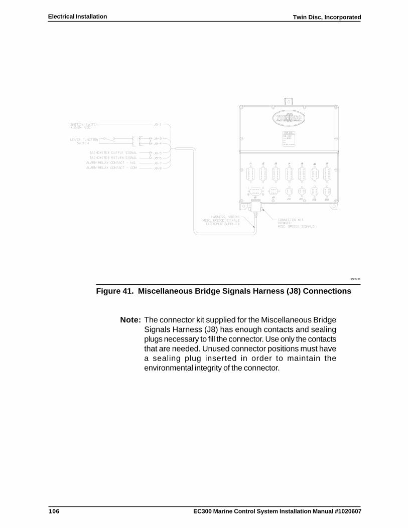
106
Twin Disc, IncorporatedElectrical Installation
EC300 Marine Control System Installation Manual #1020607
TD10036
Figure 41. Miscellaneous Bridge Signals Harness (J8) Connections
Note: The connector kit supplied for the Miscellaneous BridgeSignals Harness (J8) has enough contacts and sealingplugs necessary to fill the connector. Use only the contactsthat are needed. Unused connector positions must havea sealing plug inserted in order to maintain theenvironmental integrity of the connector.

107
Twin Disc, Incorporated Electrical Installation
EC300 Marine Control System Installation Manual #1020607
Ignition Switch Wiring
Ignition switch wiring is accomplished through the multipurpose MiscellaneousBridge Signals Harness (J8) that connects to the J8 receptacle at the EC300Control. The ignition signal turns on power to the EC300 Control. The controlwill not function unless this terminal is connected to a DC signal source fromthe load side of the ignition switch. A connector kit is supplied by Twin DiscIncorporated. Cable is customer supplied.
Note: The following instructions refer to a combination ignitionswitch. That is, the switch has an ON position and aSTART position. For this instruction, the wiring from thisswitch is from the ON position that does not open thecontacts when the engine is started. If a common masterpower switch is used to enable separate START push-buttons, then use this master ON switch as this signalsource.
Install the Ignition Switch input wiring as follows:
CAUTIONThe DC voltage from the ignition switch must be at the same voltageand from the same source as the voltage used by the EC300 Control. Itmust not be interrupted when the engine is started.
1. Connect EC300 Miscellaneous Bridge Signals Harness (J8) at thecontrol.
Note: EC300 Miscellaneous Bridge Signals Harness (J8) alsomay contain wiring for other components. Route theharness to the most convenient location serving all theapplicable connections.
2. Route the harness to the ignition switch area.
3. Connect the EC300 Miscellaneous Bridge Signals Harness J8 pin 1wire to the load side of the ignition switch.
Note: It may be desirable to complete any other terminationsfor this harness before securing the harness.
4. Secure all harnesses to a supporting structure with clamps or cable tiesat 406 mm (16 in) intervals. See Routing Requirements.

108
Twin Disc, IncorporatedElectrical Installation
EC300 Marine Control System Installation Manual #1020607
Lever Function Switch Wiring
The lever function switch is used to enable either the single lever master modecontrol of multiple engines or the phantom mode control of multiple EC300Controls from a single lever. If used, the lever function switch should be installedper Lever Function Switch Installation.
Install the Lever Function Switch input wiring as follows:
1. If required, connect EC300 Miscellaneous Bridge Signals Harness (J8)at the EC300 Control.
Note: EC300 Miscellaneous Bridge Signals Harness (J8) alsomay contain wiring for other components. Route theharness to the most convenient location serving all theapplicable connections.
2. If required, route the harness to the lever function switch area.
3. Connect the EC300 Miscellaneous Bridge Signals Harness J8 pin 3wire to the load side of the Lever Function Switch.
4. Connect the EC300 Miscellaneous Bridge Signals Harness J8 pin 4wire to the return side of the Lever Function Switch.
5. Ensure that the Lever Function Switch is securely installed.
Note: It may be desirable to complete any other terminationsfor this harness before securing the harness.
6. Secure all harnesses to a supporting structure with clamps or cable tiesat 406 mm (16 in) intervals. See Routing Requirements.

109
Twin Disc, Incorporated Electrical Installation
EC300 Marine Control System Installation Manual #1020607
Tachometer Output Wiring Installation
The tachometer output circuit is used to drive a tachometer indicator. In a retrofit,an existing speed sensor may have driven the tachometer directly from theengine or transmission output speed sensor. With the EC300 Control installation,the engine speed sensor signal can be repeated from the EC300 so that thesensor can feed the EC300 control directly.
Install the tachometer output wiring as follows:
1. If required, connect EC300 Miscellaneous Bridge Signals Harness (J8)at the control.
Note: EC300 Miscellaneous Bridge Signals Harness (J8) alsomay contain wiring for other components. Route theharness to the most convenient location serving all theapplicable connections.
2. If required, route the harness to the tachometer area.
3. Connect the EC300 Miscellaneous Bridge Signals Harness J8 pin 5wire to the signal input connection on the tachometer.
4. Connect the EC300 Miscellaneous Bridge Signals Harness J8 pin 6wire to the return connection on the tachometer.
5. If required, route power and ground wiring to the tachometer from theappropriate source.
Note: It may be desirable to complete any other terminationsfor this harness before securing the harness.
6. Secure all harnesses to a supporting structure with clamps or cable tiesat 406 mm (16 in) intervals. See Routing Requirements.

110
Twin Disc, IncorporatedElectrical Installation
EC300 Marine Control System Installation Manual #1020607
Alarm Output Wiring Installation
The EC300 Control provides an alarm relay output rated at an operating currentof 2 amp maximum. This output is used for remote audible or visual indicationof problems associated with the EC300 Control System. The EC300 output isa normally open contact that closes when an alarm condition occurs.
Note: If this output is used as an input to a digital annunciator orlow-current relay, then an intermediate relay is notnecessary. If the output drives a high current audible alarmor buzzer, then an intermediate relay is recommended.The following instructions assume the presence of anintermediate alarm relay and that the intermediate alarmrelay contacts have already been wired.
Install the alarm relay output wiring as follows:
1. If required, connect EC300 Miscellaneous Bridge Signals Harness (J8)at the control.
Note: EC300 Miscellaneous Bridge Signals Harness (J8) alsomay contain wiring for other components. Route theharness to the most convenient location serving all theapplicable connections.
2. If required, route the harness to the alarm relay area. See Figure 42.
3. Connect the EC300 Miscellaneous Bridge Signals Harness J8 pin 7wire to Positive System Voltage Source.
4. Connect the EC300 Miscellaneous Bridge Signals Harness J8 pin 8wire to the positive side of the relay coil.
5. Connect the return side of the coil to Negative System Voltage Source.
Note: It may be desirable to complete any other terminationsfor this harness before securing the harness.
6. Secure all harnesses to a supporting structure with clamps or cable tiesat 406 mm (16 in) intervals. See Routing Requirements.
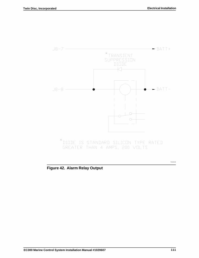
111
Twin Disc, Incorporated Electrical Installation
EC300 Marine Control System Installation Manual #1020607
TD10218
Figure 42. Alarm Relay Output
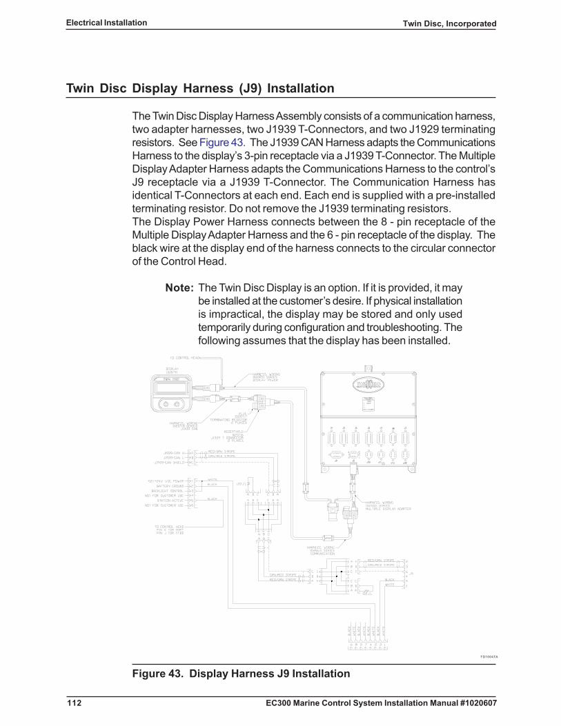
112
Twin Disc, IncorporatedElectrical Installation
EC300 Marine Control System Installation Manual #1020607
Twin Disc Display Harness (J9) Installation
The Twin Disc Display Harness Assembly consists of a communication harness,two adapter harnesses, two J1939 T-Connectors, and two J1929 terminatingresistors. See Figure 43. The J1939 CAN Harness adapts the CommunicationsHarness to the display’s 3-pin receptacle via a J1939 T-Connector. The MultipleDisplay Adapter Harness adapts the Communications Harness to the control’sJ9 receptacle via a J1939 T-Connector. The Communication Harness hasidentical T-Connectors at each end. Each end is supplied with a pre-installedterminating resistor. Do not remove the J1939 terminating resistors.The Display Power Harness connects between the 8 - pin receptacle of theMultiple Display Adapter Harness and the 6 - pin receptacle of the display. Theblack wire at the display end of the harness connects to the circular connectorof the Control Head.
Note: The Twin Disc Display is an option. If it is provided, it maybe installed at the customer’s desire. If physical installationis impractical, the display may be stored and only usedtemporarily during configuration and troubleshooting. Thefollowing assumes that the display has been installed.
TD10047A
Figure 43. Display Harness J9 Installation

113
Twin Disc, Incorporated Electrical Installation
EC300 Marine Control System Installation Manual #1020607
Connect the Twin Disc Display Harness Assembly and the Display PowerHarness as follows (See figure 43):
1. Install a 3-pin plug of the J1939 Can harness into the 3-pin receptacle ofthe Twin Disc Display.
2. Install a J1939 T-Connector onto the remaining 3-pin plug of the J1939Can harness.
3. Install a 3-pin plug of the Communications harness into the J1939 T-Connector.
4. Install the 6-pin plug of the Display Power harness into the 6-pinreceptacle of the Twin Disc Display.
5. Route the short black wire to the Control Head.
6. If required, disconnect the Control Head.
7. If required, disconnect the Control Head harness from the Control Head.
8. Install the short black wire of the Display Power harness into the Controlhead receptacle (position E for a port lever application, position J for astarboard lever application).
9. Route the Display Power harness and the Communications harness toJ9 of the EC300 Control.
10. Install a J1939 T-Connector onto the 3-pin plug of the Multiple DisplayAdapter harness.
11. Install the 3-pin plug of the Communications harness into the J1939 T-Connector
12. Remove the 8-pin receptacle from the Multiple Display Adapter harnesslocated at J9 of the EC300 Control.
13. Remove the locking wedge from the Multiple Display Adapter harness’splug (the locking wedge must be removed to properly seat the contactsinto the plug).
14. Install the white wire of the Display Power harness into position 2, 7, or8 of the 8-pin plug of the Multiple Display Adapter harness.

114
Twin Disc, IncorporatedElectrical Installation
EC300 Marine Control System Installation Manual #1020607
15. Install the black wire of the Display Power harness into position 4, 5, or6 of the 8-pin plug of the Multiple Display Adapter harness.
16. Install a J1939 terminating resistor into the J1939 T-Connectorreceptacle located at each end of the routing path for the Twin DiscDisplay Harness Assembly.
Note: Terminating resistors must be installed at each end of theTwin Disc Display Harness Assembly for thecommunications to work properly.
17. Repeat steps 1 through 16 for each additional Twin Disc Display.
18. Install the locking wedge into the Multiple Display Adapter harness’s 8-pin plug.
19. Install the 8-pin receptacle onto the Multiple Display Adapter harness’s8-pin plug.
20. Secure all harnesses to a supporting structure with clamps or cable tiesat 406mm (16 in) intervals.
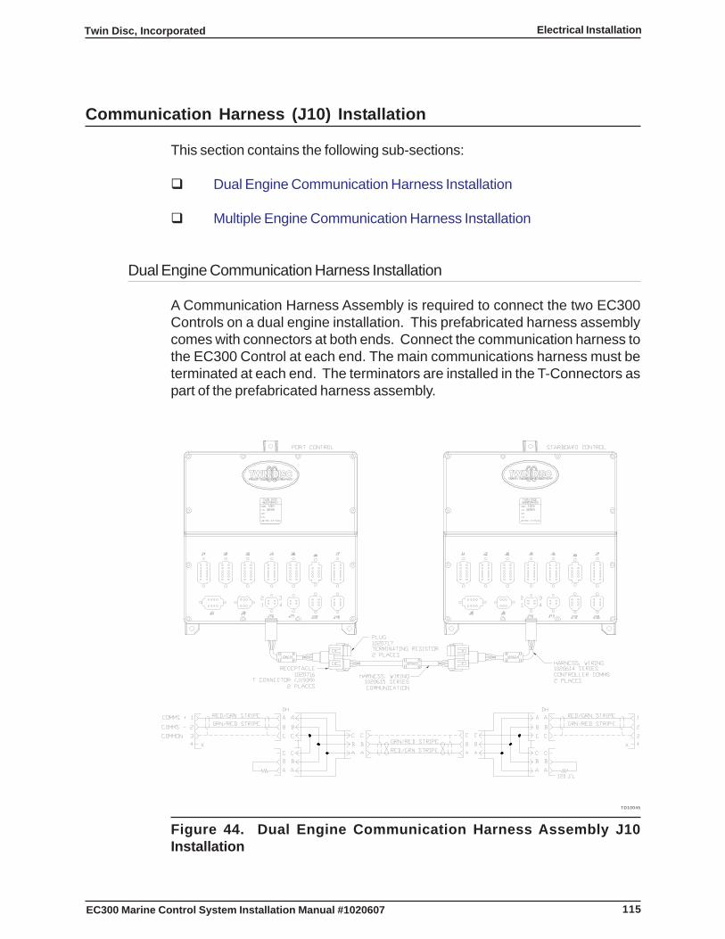
115
Twin Disc, Incorporated Electrical Installation
EC300 Marine Control System Installation Manual #1020607
Communication Harness (J10) Installation
This section contains the following sub-sections:
� Dual Engine Communication Harness Installation
� Multiple Engine Communication Harness Installation
Dual Engine Communication Harness Installation
A Communication Harness Assembly is required to connect the two EC300Controls on a dual engine installation. This prefabricated harness assemblycomes with connectors at both ends. Connect the communication harness tothe EC300 Control at each end. The main communications harness must beterminated at each end. The terminators are installed in the T-Connectors aspart of the prefabricated harness assembly.
TD10045
Figure 44. Dual Engine Communication Harness Assembly J10Installation
116
Twin Disc, IncorporatedElectrical Installation
EC300 Marine Control System Installation Manual #1020607
Connect the Communication Harness Assembly as follows (See figure 44):
Note: The specific application may have different lengths for eachsegment of communication harness. Use the correct segments.
1. Install a J1939 T-Connector receptacle on the 3-pin plug of eachController Comms Harness.
2 Install a Controller Comms Harness into the J10 receptacle of eachEC300 Control.
3. Connect the Controller Comms Harness between the EC300 Controlsby installing the 3-pin plugs into the J1939 T-Connector receptacleslocated on the Controller Comms Harness at each EC300 Control.
4. Install a J1939 Terminating Resistor into the J1939 T-Connectorreceptacle located at each end of the routing path for theCommunication Harness Assembly.
Note: Terminating resistors must be installed at each end ofthe Communication Harness Assembly for thecommunications to work properly.
5. As required, secure all harnesses to a supporting structure withclamps or cable ties at 406 mm (16 in) intervals. See RoutingRequirements.
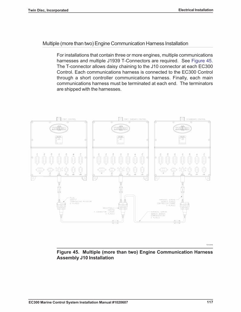
117
Twin Disc, Incorporated Electrical Installation
EC300 Marine Control System Installation Manual #1020607
Multiple (more than two) Engine Communication Harness Installation
For installations that contain three or more engines, multiple communicationsharnesses and multiple J1939 T-Connectors are required. See Figure 45.The T-connector allows daisy chaining to the J10 connector at each EC300Control. Each communications harness is connected to the EC300 Controlthrough a short controller communications harness. Finally, each maincommunications harness must be terminated at each end. The terminatorsare shipped with the harnesses.
TD10046
Figure 45. Multiple (more than two) Engine Communication HarnessAssembly J10 Installation
118
Twin Disc, IncorporatedElectrical Installation
EC300 Marine Control System Installation Manual #1020607
Connect the Communication Harness Assembly as follows (see Figure 45):
Note: The specific application may have different lengths for eachsegment of communication harness. Use the correct segments.
1. Install a J1939 T-Connector receptacle on the 3-pin plug of eachController Comms Harness.
2. Install a Controller Comms Harness into the J10 receptacle of eachEC300 Control.
3. Daisy chain the Communication Harness between the EC300Controls by installing the 3-pin plugs into the J1939 T-Connectorreceptacles located on the Controller Comms Harness at eachEC300 Control.
4. Install a J1939 Terminating Resistor into the J1939 T-Connectorreceptacle located at each end of the routing path for theCommunication Harness Assembly.
Note: Terminating resistors must be installed at each end ofthe Communication Harness Assembly for thecommunications to work properly.
5. As required, secure all harnesses to a supporting structure withclamps or cable ties at 406 mm (16 in) intervals. See RoutingRequirements.
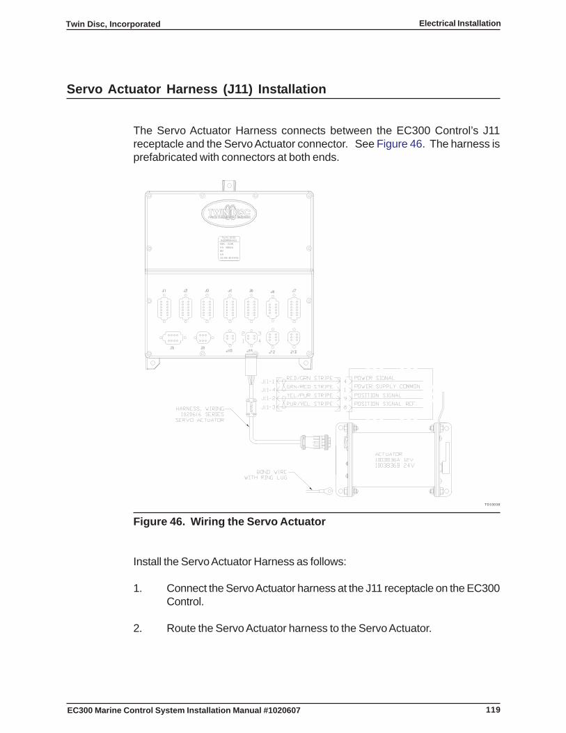
119
Twin Disc, Incorporated Electrical Installation
EC300 Marine Control System Installation Manual #1020607
Servo Actuator Harness (J11) Installation
The Servo Actuator Harness connects between the EC300 Control’s J11receptacle and the Servo Actuator connector. See Figure 46. The harness isprefabricated with connectors at both ends.
TD10038
Figure 46. Wiring the Servo Actuator
Install the Servo Actuator Harness as follows:
1. Connect the Servo Actuator harness at the J11 receptacle on the EC300Control.
2. Route the Servo Actuator harness to the Servo Actuator.

120
Twin Disc, IncorporatedElectrical Installation
EC300 Marine Control System Installation Manual #1020607
Note: To connect the connector, align the connector key with thekeyway and push the connector into place. Then, turn theconnector’s collar until engagement snap is felt.
3. Connect the harness to the Servo Actuator.
4. Repeat Steps 1 through 3 for any remaining Servo Actuators that maybe used on other EC300 Controls.
5. Secure all harnesses to a supporting structure with clamps or cable tiesat 406 mm (16 in) intervals. See Routing Requirements.
Note: The bonding conductor must be 14 AWG stranded copperwire. It must be colored green with a yellow stripe(preferred) or green in order to comply with ABYCstandards.
6. Route a bond wire from the vessel bonding system to the selectedmounting pad on each Servo Actuator. See Figure 46.
Note: The ring lug must be properly sized for both the wire andthe mounting fastener.
7. Install a ring lug on the Servo Actuator end of the wire.
8. Remove the mounting fastener at the bonding connection.
9. Remove any paint at the mounting connection in order to ensure electricalcontact.
10. Insert the bonding wire’s ring lug on the Servo Actuator.
11. Reinstall and tighten fasteners up to 1.13 Nm (10 in-lb) maximum.
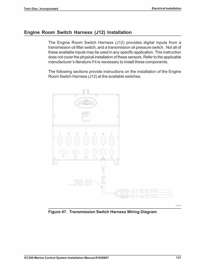
121
Twin Disc, Incorporated Electrical Installation
EC300 Marine Control System Installation Manual #1020607
Engine Room Switch Harness (J12) Installation
The Engine Room Switch Harness (J12) provides digital inputs from atransmission oil filter switch, and a transmission oil pressure switch. Not all ofthese available inputs may be used in any specific application. This instructiondoes not cover the physical installation of these sensors. Refer to the applicablemanufacturer’s literature if it is necessary to install these components.
The following sections provide instructions on the installation of the EngineRoom Switch Harness (J12) at the available switches.
TD10044
Figure 47. Transmission Switch Harness Wiring Diagram
122
Twin Disc, IncorporatedElectrical Installation
EC300 Marine Control System Installation Manual #1020607
Transmission Oil Filter Differential Pressure Switch Wiring Installation
Install the wiring connections for a Transmission Oil Filter Differential PressureSwitch as follows:
Note: The Transmission Oil Filter Differential Pressure SwitchCable is part of the Engine Room Switch harness. Cableties may be removed for routing purposes.
1. If required, connect the Engine Room Switch Harness at the J12receptacle of the EC300 Control.
2. If required, route the Engine Room Switch Harness to the TransmissionOil Filter Differential Pressure Switch area.
3. Secure all harnesses to a supporting structure with clamps or cable tiesat 406 mm (16 in) intervals. See Routing Requirements.
Note: Refer to Figure 47 for detailed information about theconductors. Refer to the transmission manufacturer’stechnical manual for any recommendations for terminatingthe wires. Refer to Wire Connections for otherrequirements.
4. Terminate the red with green stripe “OIL FILTER” J12 pin 1 wire to eitherlead for the Transmission Oil Filter Differential Pressure Switch.
5. Terminate the green with red stripe “OIL FILTER” J12 pin 2 wire to theother lead for the Transmission Oil Filter Differential Pressure Switch.

123
Twin Disc, Incorporated Electrical Installation
EC300 Marine Control System Installation Manual #1020607
Transmission Oil Pressure Switch Wiring Installation
Install the wiring connections for a Transmission Oil Pressure Switch as follows:
Note: The Transmission Oil Pressure Switch cable is part of theEngine Room Switch harness. Cable ties may be removedfor routing purposes.
1. If required, connect the Engine Room Switch Harness at the J12receptacle of the EC300 Control.
2. If required, route the Engine Room Switch Harness to the TransmissionOil Pressure Switch area.
3. Secure all harnesses to a supporting structure with clamps or cable tiesat 40 cm (16 in) intervals.
Note: Refer to Figure 47 for detailed information about theconductors. Refer to the transmission manufacturer’stechnical manual for any recommendations for terminatingthe wires. Refer to Wire Connections for otherrequirements.
4. Terminate the light blue with brown stripe “OIL PRESSURE SWITCH”J12 pin 3 wire to either lead for the Transmission Oil Pressure Switch.
5. Terminate the brown with light blue stripe “OIL PRESSURE SWITCH”J12 pin 4 wire to the other lead for the Transmission Oil Pressure Switch.
124
Twin Disc, IncorporatedElectrical Installation
EC300 Marine Control System Installation Manual #1020607
EC300 Control Power and Grounding Harness (J13) Installation
The EC300 Control operates on voltages between 10 and 28 VDC. DC to DCconverters must be used for other system voltages.
Power wiring must be a twisted pair of 14 AWG stranded copper wire. SeeTable 4.
CAUTIONObtain power either from primary distribution for the engine or directlyfrom the batteries. Primary distribution is the first location to which theheavy-duty battery wires connect.
CAUTIONController power or grounding connections can not be made at anyconductor through which motor starting current flows.
The following sub-sections provide the detailed instructions for this section:
� EC300 Control Power Wiring
� EC300 Control Bonding Installation
EC300 Control Power Wiring
Note: Refer to Power Wiring Requirements for a listing ofrequirements.
Note: Using switched power to the EC300 Control is notrecommended. However, if standards or agencies requirethat all electronic circuits have on-off control, then use thesame switched power that also feeds the engine controller.
CAUTIONUse the same source of power for the EC300 Control as used for theelectronically controlled engine, if applicable. Ensure that the circuitcurrent rating is adequate for combined load of the EC300 Control andthe engine controller.
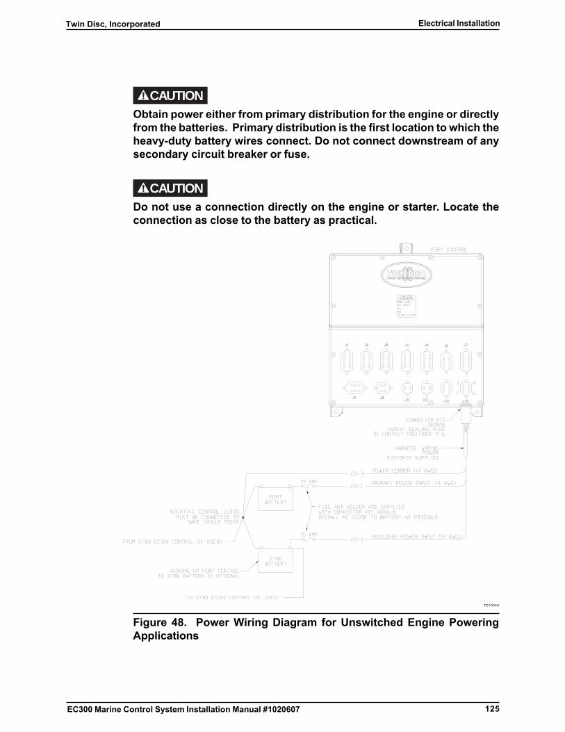
125
Twin Disc, Incorporated Electrical Installation
EC300 Marine Control System Installation Manual #1020607
CAUTIONObtain power either from primary distribution for the engine or directlyfrom the batteries. Primary distribution is the first location to which theheavy-duty battery wires connect. Do not connect downstream of anysecondary circuit breaker or fuse.
CAUTIONDo not use a connection directly on the engine or starter. Locate theconnection as close to the battery as practical.
TD10049
Figure 48. Power Wiring Diagram for Unswitched Engine PoweringApplications
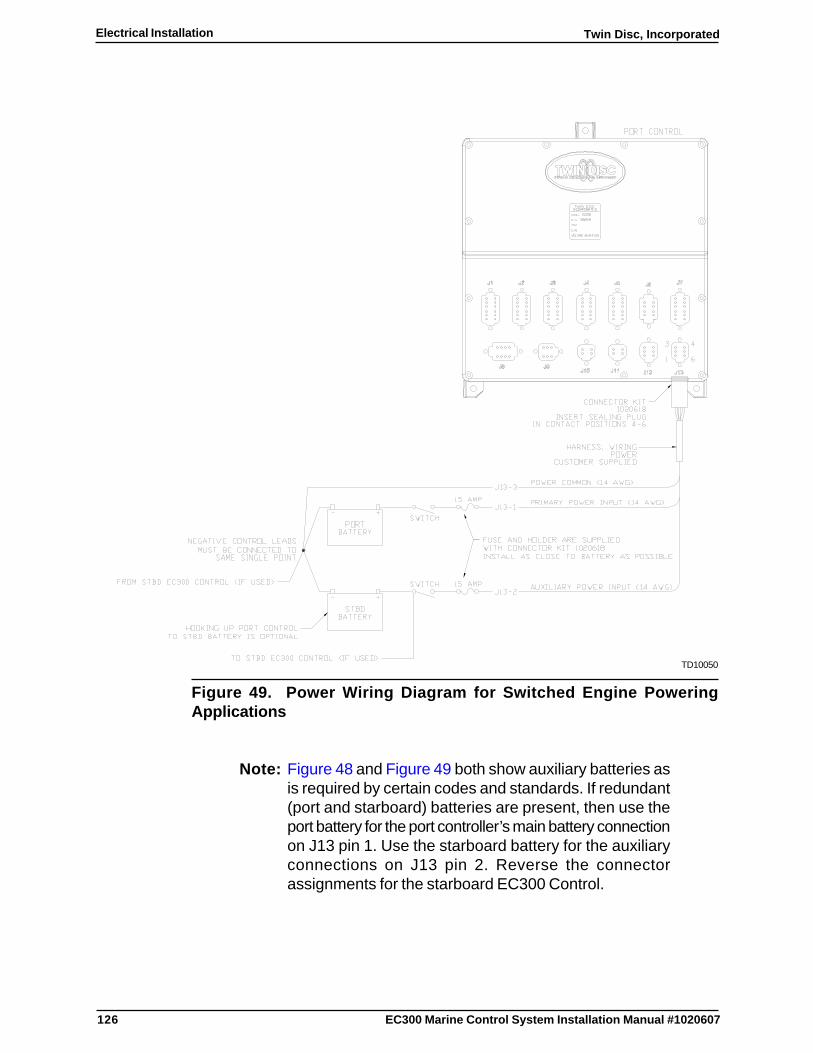
126
Twin Disc, IncorporatedElectrical Installation
EC300 Marine Control System Installation Manual #1020607
TD10050
Figure 49. Power Wiring Diagram for Switched Engine PoweringApplications
Note: Figure 48 and Figure 49 both show auxiliary batteries asis required by certain codes and standards. If redundant(port and starboard) batteries are present, then use theport battery for the port controller’s main battery connectionon J13 pin 1. Use the starboard battery for the auxiliaryconnections on J13 pin 2. Reverse the connectorassignments for the starboard EC300 Control.
127
Twin Disc, Incorporated Electrical Installation
EC300 Marine Control System Installation Manual #1020607
Note: Figure 48 and Figure 49 both show two single batteries.This is typical for 12 VDC systems using 12 VDCbatteries. The 24 VDC system typically connects two 12VDC batteries in series to obtain 24 VDC. However, 6VDC batteries can also be connected in series to achieveeither 12 VDC or 24 VDC. Additionally, batteries can beconnected in parallel in order to increase the availablebattery current. If uncertain about which battery terminalsare to be used, check the voltage with a multimeter.
Install the control power wiring as follows:
1. If required, install two fuses or circuit breakers at the battery positive orengine controller power distribution connections. See Power WiringRequirements.
2. If required, route power wiring to the fuses or circuit breakers.
3. Temporarily remove the fuses or open the circuit breakers.
Note: Power wiring must be a twisted pair of 14 AWG strandedcopper wire. See Power Wiring Requirements.
Ensure that the EC300 Control power wiring is electrically identical tothat used for any associated engine controller.
4. Connect the first red wire going to EC300 Control Connector J13 Pin 1to the load side of Main Battery fuse or circuit breaker.
Note: If no auxiliary battery is present, do not install a wire toJ13 Pin 2. Pin 2 should be plugged.
5. Connect the second red wire going to EC300 Control Connector J13Pin 2 to the load side of the Auxiliary Battery fuse or circuit breaker.
CAUTIONThe EC300 Control’s negative power connection must be made at thesame point that the two batteries share a common negative connection.That is, the two batteries must share a common negative connectionand the EC300 Control’s negative power connection must be made atthe same point.
128
Twin Disc, IncorporatedElectrical Installation
EC300 Marine Control System Installation Manual #1020607
6. Connect the yellow (preferred) or black wire going to EC300 ControlConnector J13 Pin 3 to the DC Grounding Bus or the DC Negative Busas is applicable.
Note: Refer to Routing Requirements.
7. Route the EC300 Control Power and Grounding Harness (J13) to theassociated EC300 Control.
Note: The Deutsch contacts (14 AWG) (P/N 0462-209-16141)have a green band.
8. Using the Deutsch crimping tool (P/N HDT 48-00), crimp the wires tothe Deutsch contacts (14 AWG) (P/N 0462-209-16141).
9. Assemble the J13 Deutsch Mating Connector (P/N DT06-6S-P012).See Figure 48.
10. Ensure that sealing plugs are installed in all empty connector positions.
11. Ensure that the assembled harness is properly supported and protected.
Note: For vessels complying with American Bureau of Shipping(ABS) Rules for Building and Classing Steel Vessels 2002or Rules for Building and Classing Steel Vessels Under90 Meters (295 Feet) 2001, insulation resistance of powerand lighting cables is to be measured. Appliancesconnected to the circuits may be disconnected for thistest. Each power and each lighting circuit is to have aninsulation resistance between conductors and betweeneach conductor and earth of not less than 0.4 Megohmsfor loads less than 25 amps.
12. Ensure that the power harness conductors for J13 pin 1 through J13 pin6 are disconnected at both ends.
13. Using a 500 VDC Megohmmeter or equivalent, measure the resistancebetween each of the following sets of conductors:
� J13 pin 1 and Earth or Bonding System
� J13 pin 2 and Earth or Bonding System
� J13 pin 3 and Earth or Bonding System

129
Twin Disc, Incorporated Electrical Installation
EC300 Marine Control System Installation Manual #1020607
14. Verify that all measurements are greater than or equal to 0.4 Megohms.
Note: Leave EC300 Control Power and Grounding Harness(J13) disconnected from the EC300 Control until all wiringhas been completed.

130
Twin Disc, IncorporatedElectrical Installation
EC300 Marine Control System Installation Manual #1020607
EC300 Control Bonding Installation
The EC300 Control enclosure connects directly to the surface on which it ismounted. For both conductive and nonconductive vessels, the bondingconnection is also made in order to ensure that the metallic enclosure is bonded.Bonding provides a means of making a controlled path for the removal ofelectrical noise that could be introduced to the EC300 Control through the wiringby inductive interference from motors or generators or by electromagneticinterference from radar or radios. Applicable codes may prevent bondingconnections to the battery negative. Some codes do require that the bondingconnection and battery negative are connected at one point only. Other codesrequire that there be no connection between the bonding system and the batterynegative. Install the bonding system as per the applicable code.
CAUTIONThe bonding wire used for the EC300 Control must be connected to thesame bonding system as used for the engine. Ground the EC300 Controlbonding wire to the negative battery terminal only if the engine isgrounded to the negative battery terminal.
Note: The bonding conductor must be 14 AWG stranded copperwire. It must be colored green with a yellow stripe(preferred) or green in order to comply with ABYCstandards.
Install the EC300 Control bonding connection as follows:
1. Route a bond wire, connected to the vessel bonding system, to one ofthe unpainted mounting feet of each EC300 Control. See Figure 50.
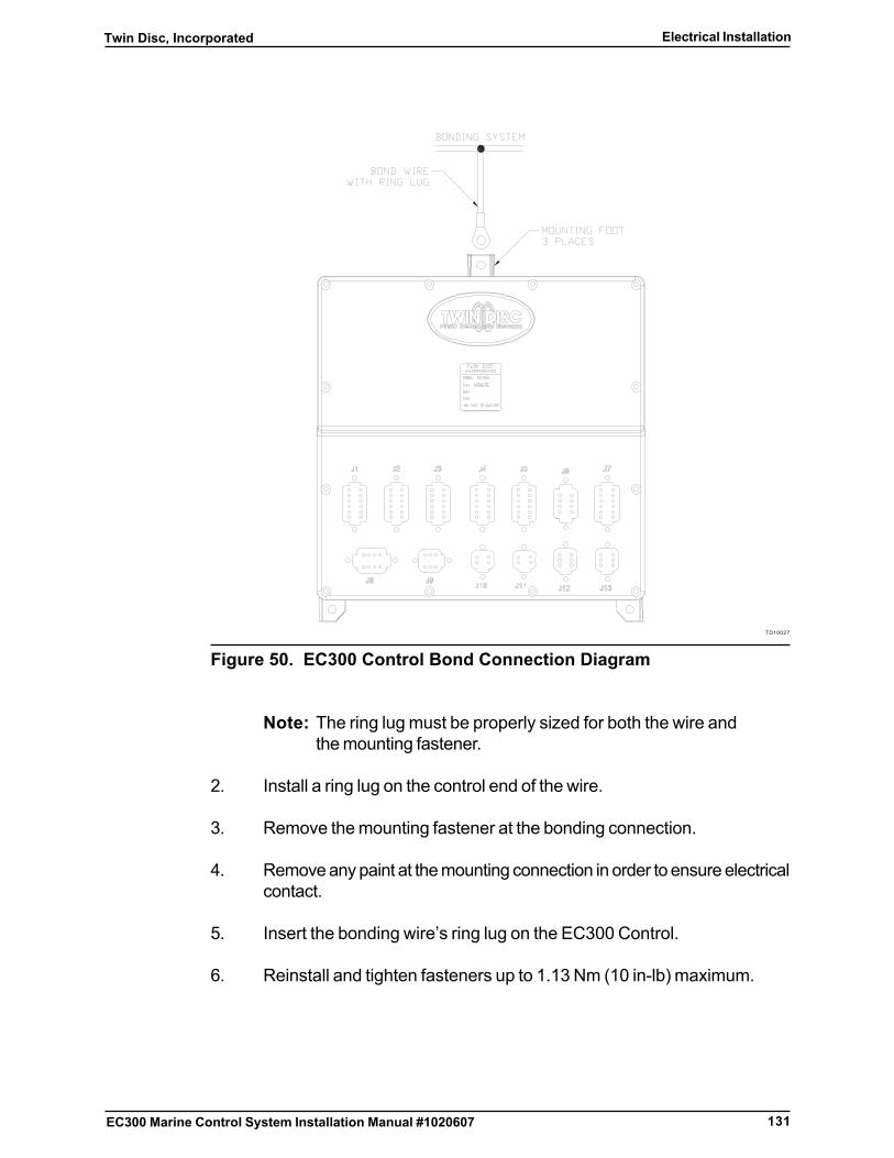
131
Twin Disc, Incorporated Electrical Installation
EC300 Marine Control System Installation Manual #1020607
TD10027
Figure 50. EC300 Control Bond Connection Diagram
Note: The ring lug must be properly sized for both the wire andthe mounting fastener.
2. Install a ring lug on the control end of the wire.
3. Remove the mounting fastener at the bonding connection.
4. Remove any paint at the mounting connection in order to ensure electricalcontact.
5. Insert the bonding wire’s ring lug on the EC300 Control.
6. Reinstall and tighten fasteners up to 1.13 Nm (10 in-lb) maximum.

132
Twin Disc, IncorporatedElectrical Installation
EC300 Marine Control System Installation Manual #1020607
This page intentionally blank
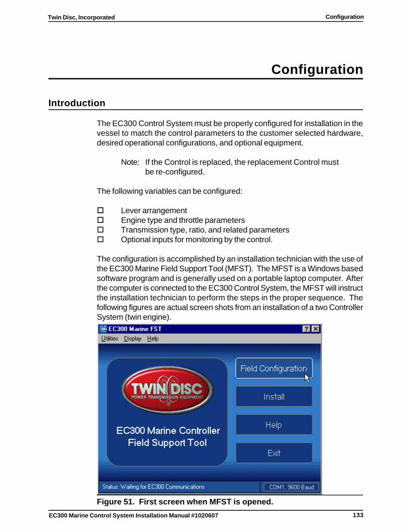
133
Twin Disc, Incorporated Configuration
EC300 Marine Control System Installation Manual #1020607
Configuration
Introduction
The EC300 Control System must be properly configured for installation in thevessel to match the control parameters to the customer selected hardware,desired operational configurations, and optional equipment.
Note: If the Control is replaced, the replacement Control mustbe re-configured.
The following variables can be configured:
o Lever arrangemento Engine type and throttle parameterso Transmission type, ratio, and related parameterso Optional inputs for monitoring by the control.
The configuration is accomplished by an installation technician with the use ofthe EC300 Marine Field Support Tool (MFST). The MFST is a Windows basedsoftware program and is generally used on a portable laptop computer. Afterthe computer is connected to the EC300 Control System, the MFST will instructthe installation technician to perform the steps in the proper sequence. Thefollowing figures are actual screen shots from an installation of a two ControllerSystem (twin engine).
Figure 51. First screen when MFST is opened.

134
Twin Disc, IncorporatedConfiguration
EC300 Marine Control System Installation Manual #1020607
Configure the Control System
This section refers to configuring the system in the field, so clicking on the FieldConfiguration tab will start the process. Note that there is an extensive helpsection, and additional explanations can be seen by clicking on the ? in theupper right of the screen, and dragging it over a subject.Click on the Field Setup tab to start the configuration process.
Figure 52. Field Configuration Menu
Note: It is very important to follow the steps in the propersequence as directed by the prompts.
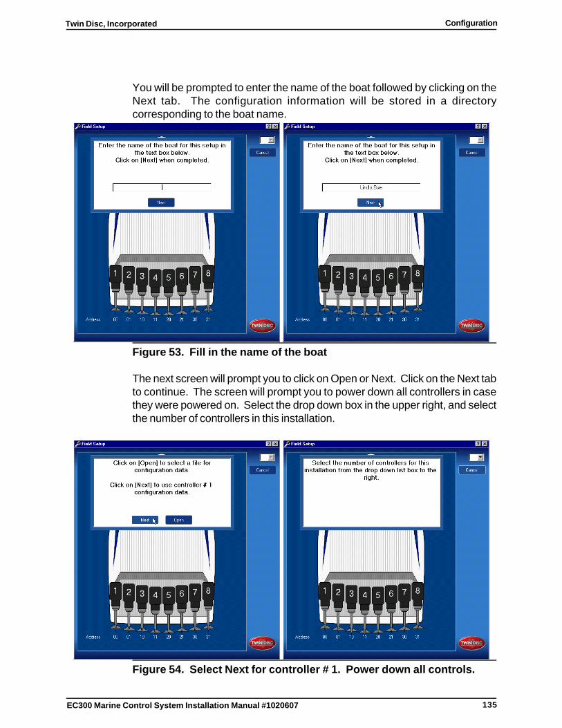
135
Twin Disc, Incorporated Configuration
EC300 Marine Control System Installation Manual #1020607
You will be prompted to enter the name of the boat followed by clicking on theNext tab. The configuration information will be stored in a directorycorresponding to the boat name.
Figure 53. Fill in the name of the boat
The next screen will prompt you to click on Open or Next. Click on the Next tabto continue. The screen will prompt you to power down all controllers in casethey were powered on. Select the drop down box in the upper right, and selectthe number of controllers in this installation.
Figure 54. Select Next for controller # 1. Power down all controls.
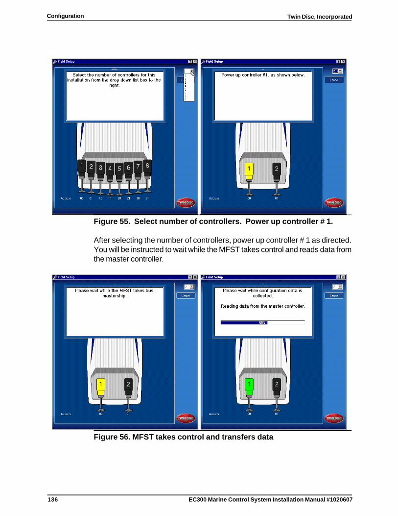
136
Twin Disc, IncorporatedConfiguration
EC300 Marine Control System Installation Manual #1020607
Figure 55. Select number of controllers. Power up controller # 1.
After selecting the number of controllers, power up controller # 1 as directed.You will be instructed to wait while the MFST takes control and reads data fromthe master controller.
Figure 56. MFST takes control and transfers data
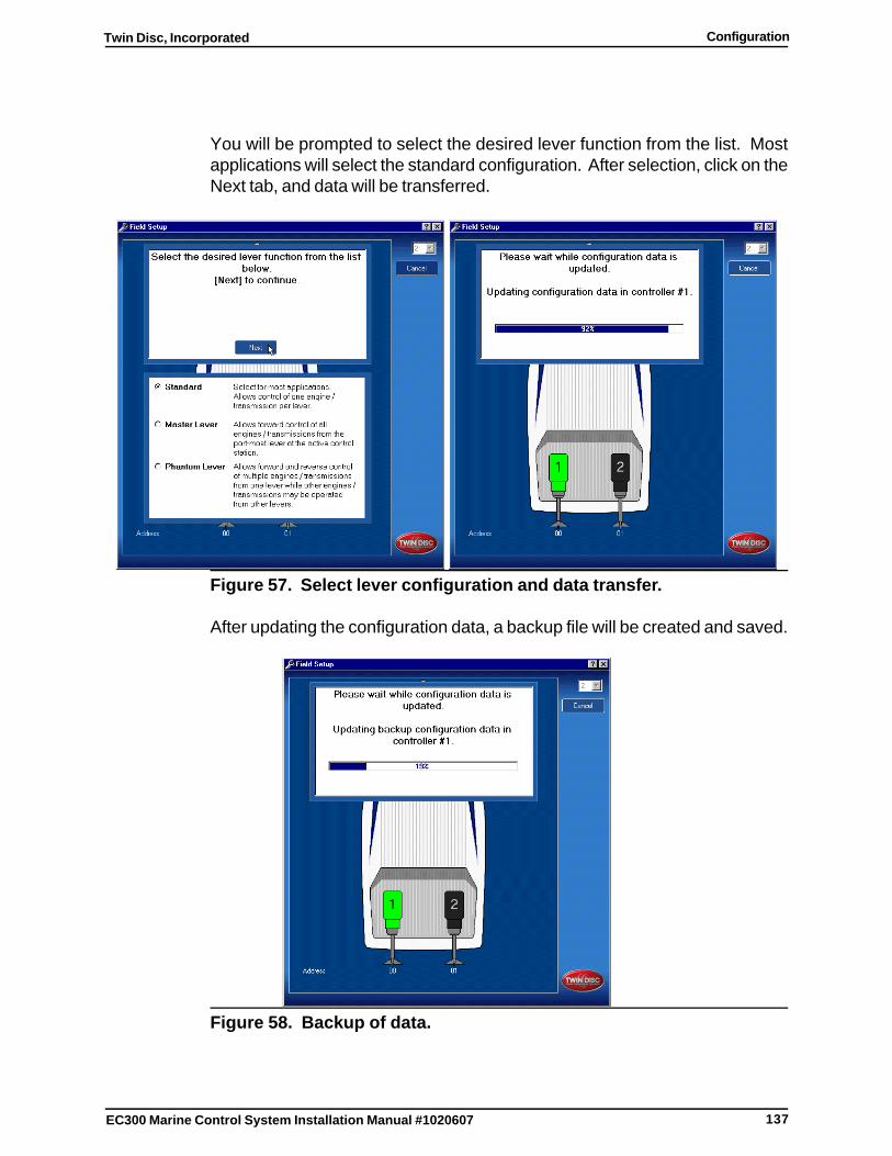
137
Twin Disc, Incorporated Configuration
EC300 Marine Control System Installation Manual #1020607
You will be prompted to select the desired lever function from the list. Mostapplications will select the standard configuration. After selection, click on theNext tab, and data will be transferred.
Figure 57. Select lever configuration and data transfer.
After updating the configuration data, a backup file will be created and saved.
Figure 58. Backup of data.
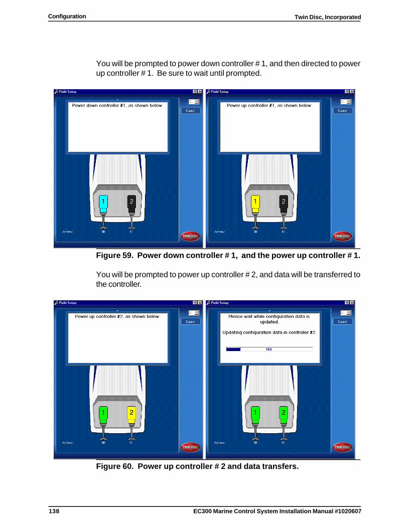
138
Twin Disc, IncorporatedConfiguration
EC300 Marine Control System Installation Manual #1020607
You will be prompted to power down controller # 1, and then directed to powerup controller # 1. Be sure to wait until prompted.
Figure 59. Power down controller # 1, and the power up controller # 1.
You will be prompted to power up controller # 2, and data will be transferred tothe controller.
Figure 60. Power up controller # 2 and data transfers.
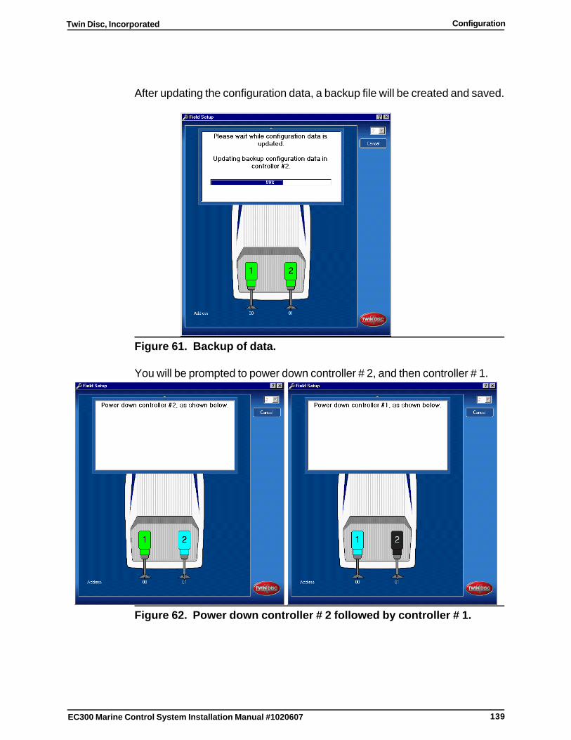
139
Twin Disc, Incorporated Configuration
EC300 Marine Control System Installation Manual #1020607
After updating the configuration data, a backup file will be created and saved.
Figure 61. Backup of data.
You will be prompted to power down controller # 2, and then controller # 1.
Figure 62. Power down controller # 2 followed by controller # 1.
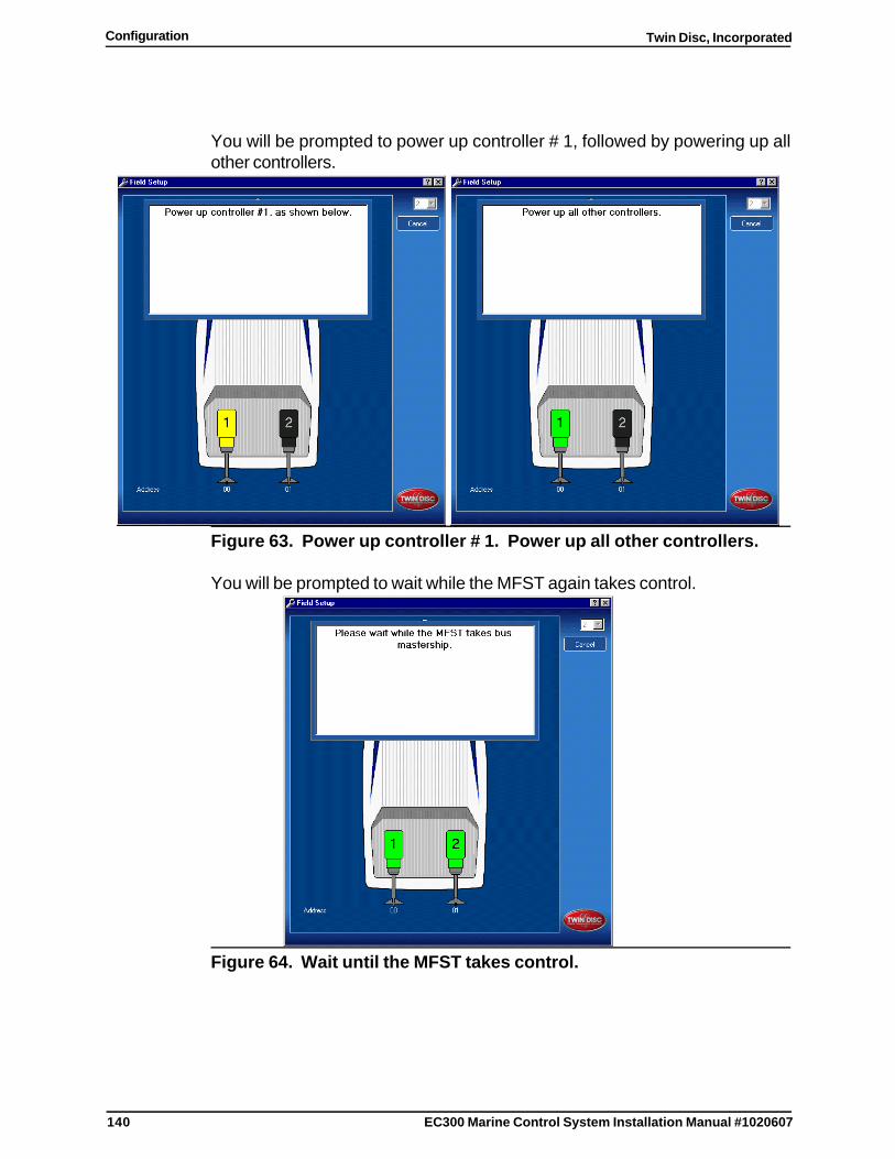
140
Twin Disc, IncorporatedConfiguration
EC300 Marine Control System Installation Manual #1020607
You will be prompted to power up controller # 1, followed by powering up allother controllers.
Figure 63. Power up controller # 1. Power up all other controllers.
You will be prompted to wait while the MFST again takes control.
Figure 64. Wait until the MFST takes control.
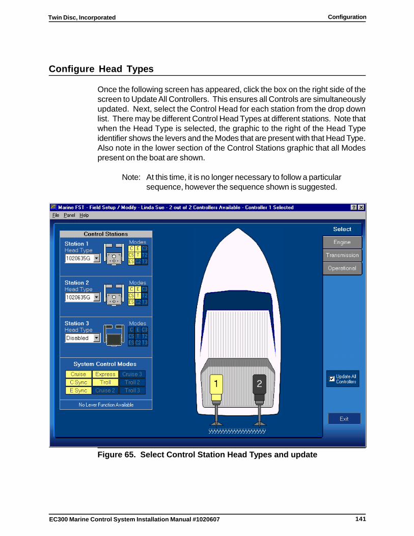
141
Twin Disc, Incorporated Configuration
EC300 Marine Control System Installation Manual #1020607
Configure Head Types
Once the following screen has appeared, click the box on the right side of thescreen to Update All Controllers. This ensures all Controls are simultaneouslyupdated. Next, select the Control Head for each station from the drop downlist. There may be different Control Head Types at different stations. Note thatwhen the Head Type is selected, the graphic to the right of the Head Typeidentifier shows the levers and the Modes that are present with that Head Type.Also note in the lower section of the Control Stations graphic that all Modespresent on the boat are shown.
Note: At this time, it is no longer necessary to follow a particularsequence, however the sequence shown is suggested.
Figure 65. Select Control Station Head Types and update
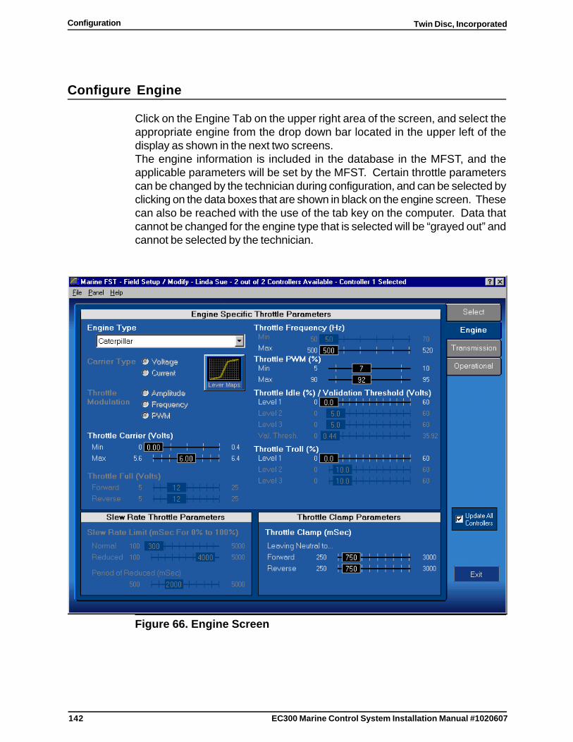
142
Twin Disc, IncorporatedConfiguration
EC300 Marine Control System Installation Manual #1020607
Configure Engine
Click on the Engine Tab on the upper right area of the screen, and select theappropriate engine from the drop down bar located in the upper left of thedisplay as shown in the next two screens.The engine information is included in the database in the MFST, and theapplicable parameters will be set by the MFST. Certain throttle parameterscan be changed by the technician during configuration, and can be selected byclicking on the data boxes that are shown in black on the engine screen. Thesecan also be reached with the use of the tab key on the computer. Data thatcannot be changed for the engine type that is selected will be “grayed out” andcannot be selected by the technician.
Figure 66. Engine Screen
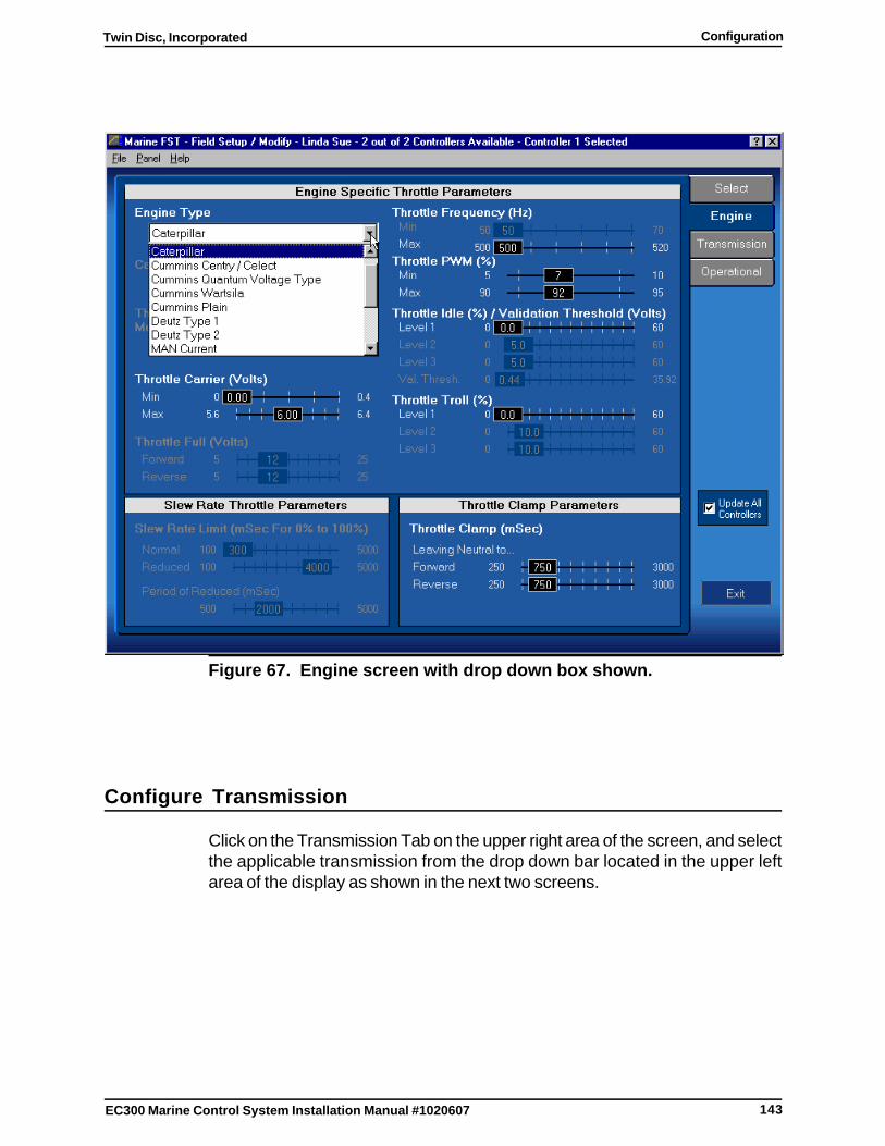
143
Twin Disc, Incorporated Configuration
EC300 Marine Control System Installation Manual #1020607
Figure 67. Engine screen with drop down box shown.
Configure Transmission
Click on the Transmission Tab on the upper right area of the screen, and selectthe applicable transmission from the drop down bar located in the upper leftarea of the display as shown in the next two screens.
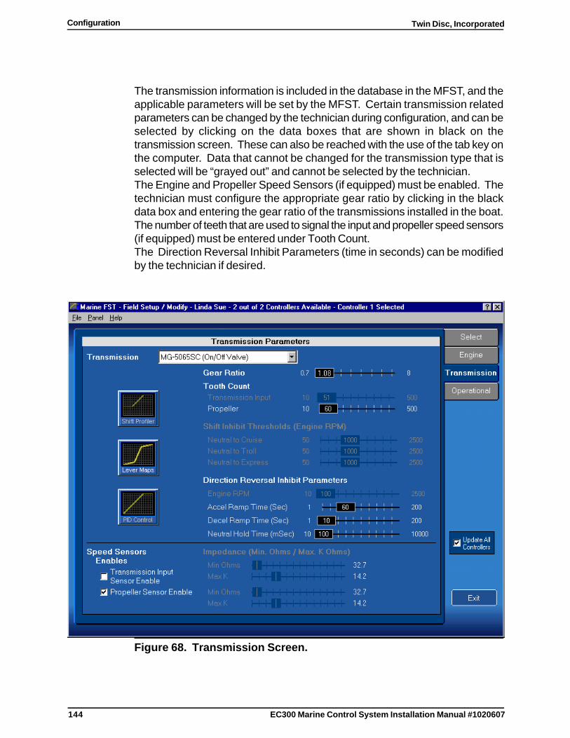
144
Twin Disc, IncorporatedConfiguration
EC300 Marine Control System Installation Manual #1020607
The transmission information is included in the database in the MFST, and theapplicable parameters will be set by the MFST. Certain transmission relatedparameters can be changed by the technician during configuration, and can beselected by clicking on the data boxes that are shown in black on thetransmission screen. These can also be reached with the use of the tab key onthe computer. Data that cannot be changed for the transmission type that isselected will be “grayed out” and cannot be selected by the technician.The Engine and Propeller Speed Sensors (if equipped) must be enabled. Thetechnician must configure the appropriate gear ratio by clicking in the blackdata box and entering the gear ratio of the transmissions installed in the boat.The number of teeth that are used to signal the input and propeller speed sensors(if equipped) must be entered under Tooth Count.The Direction Reversal Inhibit Parameters (time in seconds) can be modifiedby the technician if desired.
Figure 68. Transmission Screen.
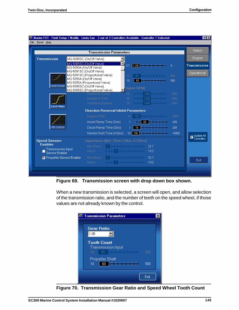
145
Twin Disc, Incorporated Configuration
EC300 Marine Control System Installation Manual #1020607
Figure 69. Transmission screen with drop down box shown.
When a new transmission is selected, a screen will open, and allow selectionof the transmission ratio, and the number of teeth on the speed wheel, if thosevalues are not already known by the control.
Figure 70. Transmission Gear Ratio and Speed Wheel Tooth Count
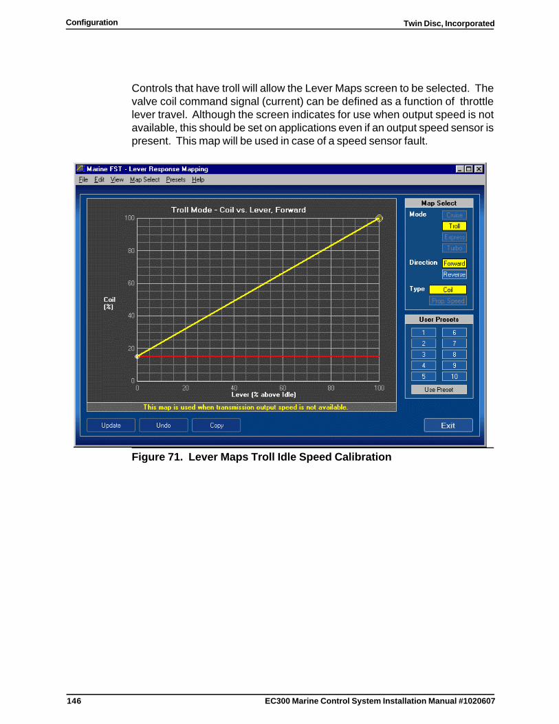
146
Twin Disc, IncorporatedConfiguration
EC300 Marine Control System Installation Manual #1020607
Controls that have troll will allow the Lever Maps screen to be selected. Thevalve coil command signal (current) can be defined as a function of throttlelever travel. Although the screen indicates for use when output speed is notavailable, this should be set on applications even if an output speed sensor ispresent. This map will be used in case of a speed sensor fault.
Figure 71. Lever Maps Troll Idle Speed Calibration
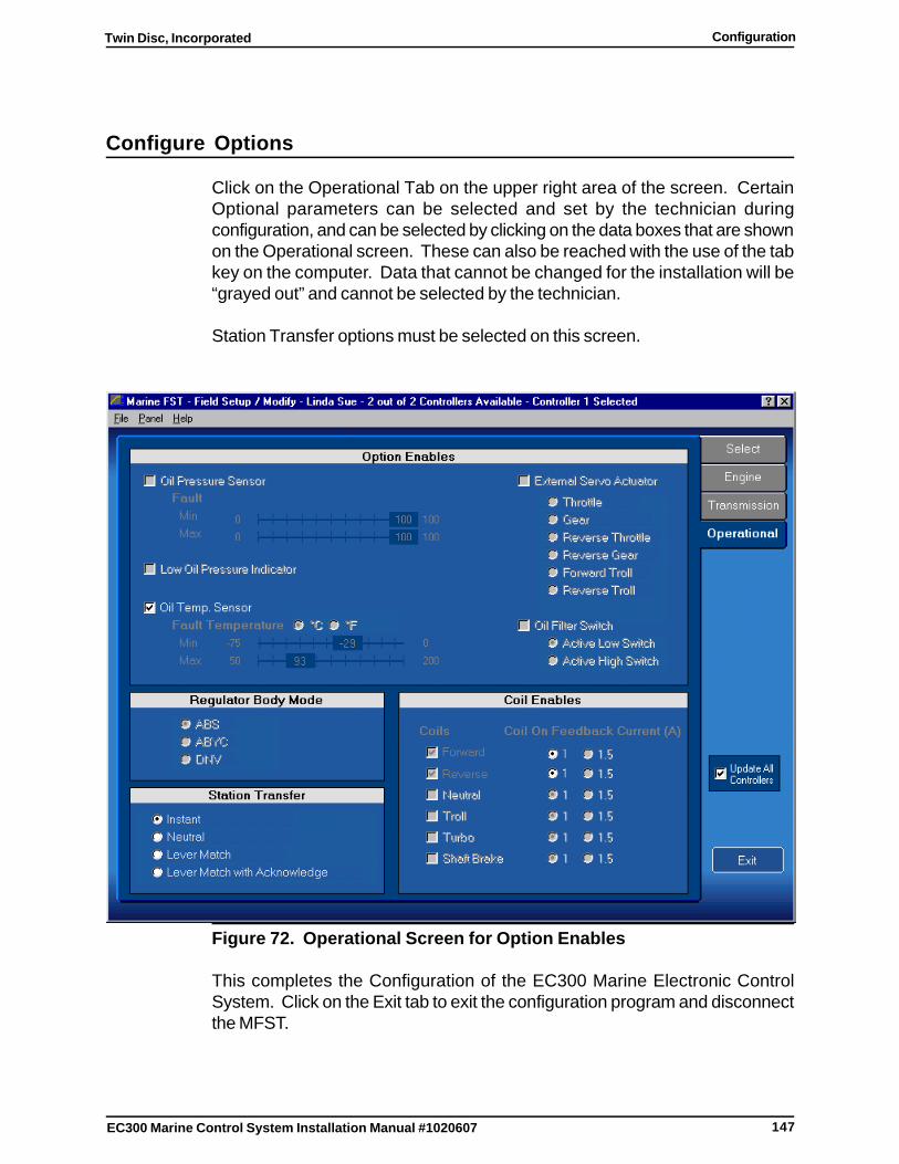
147
Twin Disc, Incorporated Configuration
EC300 Marine Control System Installation Manual #1020607
Configure Options
Click on the Operational Tab on the upper right area of the screen. CertainOptional parameters can be selected and set by the technician duringconfiguration, and can be selected by clicking on the data boxes that are shownon the Operational screen. These can also be reached with the use of the tabkey on the computer. Data that cannot be changed for the installation will be“grayed out” and cannot be selected by the technician.
Station Transfer options must be selected on this screen.
Figure 72. Operational Screen for Option Enables
This completes the Configuration of the EC300 Marine Electronic ControlSystem. Click on the Exit tab to exit the configuration program and disconnectthe MFST.
148
Twin Disc, IncorporatedConfiguration
EC300 Marine Control System Installation Manual #1020607
Miscellaneous Configuration Notes
Acceleration Ramp Time (sec)
In cruise mode, record the time (in seconds) to accelerate from the vesselspeed with the Control Head Lever(s) in the Idle Detent position to maximumvessel speed with the Control Head Lever in the full throttle position.
Deceleration Ramp Time (sec)
In cruise mode, operate the vessel at full throttle until moving at full speed.Record the time for the vessel to coast to a stop when the Control Head Lever(s)are moved to the Idle Detent position.
Throttle Clamp (msec)
These values should be set to the time it takes for the clutch engagement profilesto command 100% coil current. These values can be viewed on thetransmission parameter screen by pressing the Shift Profiler select button.
Lever Calibration
All Levers on all Control Heads at all stations must be calibrated. This can bedone via the Twin Disc Display as described in Test 3 (STATN TEST) in theTroubleshooting Section. Alternately, this can be done via the MFST Diagnostics.
149
Twin Disc, Incorporated System Operation
EC300 Marine Control System Installation Manual #1020607
System Operation
Introduction
This section includes basic operating information for the EC300 Control System.
The following sub-sections make up this section:
� Introduction
� Basic System Features
� Lever Function in Cruise Mode
� Lever Function in Express Mode
� Lever Function in Troll Mode
� Lever Function in Master Lever Function
� Lever Function in Phantom Lever Function
� Mode Select Switch
� Display Features
� Station Transfer
� Manual Mechanical Control
� Engine synchronization
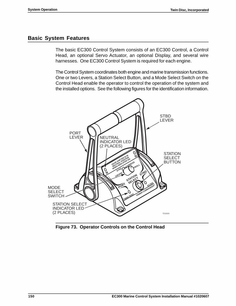
150
Twin Disc, IncorporatedSystem Operation
EC300 Marine Control System Installation Manual #1020607
Basic System Features
The basic EC300 Control System consists of an EC300 Control, a ControlHead, an optional Servo Actuator, an optional Display, and several wireharnesses. One EC300 Control System is required for each engine.
The Control System coordinates both engine and marine transmission functions.One or two Levers, a Station Select Button, and a Mode Select Switch on theControl Head enable the operator to control the operation of the system andthe installed options. See the following figures for the identification information.
STATION
SELECT
PORTR
STBD
TWIN DISC
NCRUISE
P0WER COMMANDER
GEAR SHIFTER IS IN
NEUTRAL POSITION
WHEN INDICATOR ON.
EC300R
SYNC TROLLEXPRESS
N
R
TD10103
STBDLEVER
NEUTRALINDICATOR LED(2 PLACES)
STATION SELECTINDICATOR LED(2 PLACES)
STATIONSELECTBUTTON
PORTLEVER
MODESELECTSWITCH
Figure 73. Operator Controls on the Control Head

151
Twin Disc, Incorporated System Operation
EC300 Marine Control System Installation Manual #1020607
Figure 74. Side View of Control Head
Note: A single lever Control Head will have only one lever.
Each Lever controls gear selection and throttle for one engine/gear set. If theboat is equipped with Phantom or Master Lever configured controls, each Levermay control two or more engine/transmission sets. A separate switch (notshown) is used to select multiple Engine/Transmission control from one Lever.The Station Select Button on the Control Head takes command at a specificlocation. The red Station Select Indicator LED light(s) next to the Station SelectButton verify that the Control Head is active when continuously illuminated. Whenthe Station Select Indicator LED is flashing or off, the Control Head is not active.
The Mode Select Switch on the Control Head selects up to three engine cruisespeeds, up to three trolling speeds, and/or optional Engine Synchronization, orExpress Modes.
The yellow Neutral Indicator LED light(s) provide for transmission statusindication. Each Neutral Indicator LED will light constantly if the Transmissionis in Neutral. It will flash if the Controller is in the Direction Disable Mode duringengine warm-up. See Engine Warm-up while using direction Disable Mode.
152
Twin Disc, IncorporatedSystem Operation
EC300 Marine Control System Installation Manual #1020607
Lever Function in Cruise Mode
Selecting Forward (Ahead)
Move the Lever toward the bow of the boat to the Ahead Detent Position inorder to select the ahead vessel direction. At this position, the transmissionshifts into the forward or ahead gear. The remaining Lever travel after theAhead Detent Position controls the engine throttle.
Selecting Reverse (Astern)
Move the Lever toward the stern of the boat to the Astern Detent Position inorder to select the reverse vessel direction. At this position, the transmissionshifts into the reverse or astern gear. The remaining Lever travel after the AsternDetent Position controls the engine throttle.
Direction Reversal
Reversals of direction can be made at any time. An automatic timed sequenceforces the throttle to idle while the vessel slows before engaging the clutch forthe opposite direction. This is followed by the return of the engine throttle to theposition called for by the Lever.
153
Twin Disc, Incorporated System Operation
EC300 Marine Control System Installation Manual #1020607
Lever Function in Express Mode
This mode allows the operator to achieve very low propeller speed by meansof a controlled slipping clutch when the Lever is placed in the Ahead Detent orAstern Detent Position. Slight propeller speed variation at the Detent Positionis normal in Express Mode. The propeller speed and engine speed will increaseas the Lever is advanced, until the lever reaches a point where the clutch is fullyengaged and then engine speed continues to increase as Lever positionincreases.
The propeller speed at the Ahead Detent Position is calibrated by the operatorplacing the Port Lever in the Ahead Detent Position, and the Starboard Leverin the Neutral Detent Position, and then holding the Station Select Buttondepressed for more than two seconds. While keeping the Station Select Buttondepressed, the operator advances the Lever until the desired propeller speedis achieved. At this time, the operator releases the Station Select Button andthen momentarily depresses the Station Select Button twice, and moves theLever to the Neutral Detent Position. Note that if the optional display is present,it will prompt the user during this process.
Repeat the above procedure for the Starboard Lever.

154
Twin Disc, IncorporatedSystem Operation
EC300 Marine Control System Installation Manual #1020607
Lever Function in Troll Mode
This mode allows the operation of the vessel at low speed by means of acontrolled slipping clutch with the engine speed fixed, and the Lever controllingthe propeller speed.
The propeller speed at the Ahead Detent Position is calibrated by the operatorplacing the Port and Starboard Levers in the Ahead Detent Position and thenholding the Station Select Button Depressed for at least two seconds. Theyellow Neutral LED flashes at a rate proportional to propeller speed. Whilekeeping the Station Select Button depressed, the operator then slowly advancesthe port Lever until the desired propeller speed is achieved on both the portand starboard sides. At this time, the operator releases the Station SelectButton and then momentarily depresses the Station Select Button twice, andmoves the Levers to the Neutral Detent Position. The propeller speed at theAhead Detent Position is now updated and stored in memory for both the portand starboard controls. Note that if the optional display is present, it will promptthe user during this process.

155
Twin Disc, Incorporated System Operation
EC300 Marine Control System Installation Manual #1020607
Lever Function in Master Lever Function
The Master Lever Function allows multiple engine vessels to be operated fromthe port most Lever at the active Control Station in the Ahead direction only.Although this function can be used on dual engine vessels, it is more commonlyemployed on vessels with three or more engines. The function can only beengaged when all Levers at the active Control Station are in the Ahead DetentPosition, and The Master Lever Function Switch is on. The Master LeverFunction is cancelled if any Lever at the active Control Station is moved out ofAhead or if the Master Lever Function Switch is turned off. When the MasterLever Function is active, all Controls in the system receive their Lever positioncommands and Mode Switch command from the port most Lever. Alltransmissions on the vessel will be in the Ahead gear, all Controls will beoperating in the same Mode, and all engines will be operating at the samethrottle setting. If the Master Lever function cannot be engaged, all controls willcontinue to use their own Lever and System Mode commands.
CAUTIONWhen the Master Lever Function is cancelled, for any reason, eachControl will revert to receiving throttle commands and system modecommands from its own Lever. If the position of the port Lever issignificantly different from the position of the control’s own Lever, thiscan potentially cause abrupt changes in vessel speed.

156
Twin Disc, IncorporatedSystem Operation
EC300 Marine Control System Installation Manual #1020607
Lever Function in Phantom Lever Function
The Phantom Lever Function allows multiple engines in a multiple engine vesselto be operated from one Lever while other engines are operated from otherLevers. Although this function can be used on dual engine vessels, it is morecommonly employed on vessels with three or more engines. This function canonly be engaged when all Levers at the active Control Station are at the NeutralDetent Position and the Phantom Lever Function Switch is on. When the systemis configured, one or more Controls are designated as phantom masters.Likewise, one or more Controls are designated as phantom slaves. A vesselemploying the Phantom Lever Function must have at least one phantom masterand one phantom slave. During configuration, when a control is designated asa phantom slave, it must also be assigned to a phantom master. When thePhantom Lever Function is engaged, all slaves receive throttle, gear, and systemMode commands from the phantom master to which they were assigned duringconfiguration. The phantom slave control then operates at the same throttle,gear, and system mode settings as the master Control. The Phantom LeverFunction is cancelled if any slave’s Lever is moved from the Neutral DetentPosition or if the Phantom Lever Function Switch is turned off.
Note: The system will engage the Phantom Lever function bydefault if a Control Station is made active and any slaveControl does not have a Lever attached to that station. Inthis case, the slave control will receive throttle, gear, andsystem Mode commands from its assigned master. If thePhantom Lever Function cannot be engaged, all slaveControls will command their engine to idle and theirtransmission to Neutral.
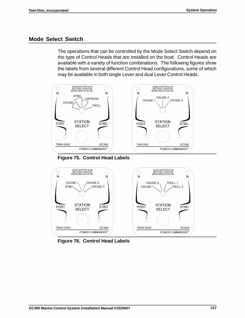
157
Twin Disc, Incorporated System Operation
EC300 Marine Control System Installation Manual #1020607
Mode Select Switch
The operations that can be controlled by the Mode Select Switch depend onthe type of Control Heads that are installed on the boat. Control Heads areavailable with a variety of function combinations. The following figures showthe labels from several different Control Head configurations, some of whichmay be available in both single Lever and dual Lever Control Heads.
��������������
����
�
�����
������
����������
����������������
����� ��������
�������
�����������������
��
��� ��
�
��������������
����
��������
�
�������
���������
�������
����������������
����� ��������
�����������������
�������
�
Figure 75. Control Head Labels
��������������
����
�
���� ������
������
����������
�������
����������������
����� ��������
�����������������
�������
�
��������������
��������
����
�
������
����������
��� ��
����������������
����� ��������
�����������������
�������
��� �
�
Figure 76. Control Head Labels
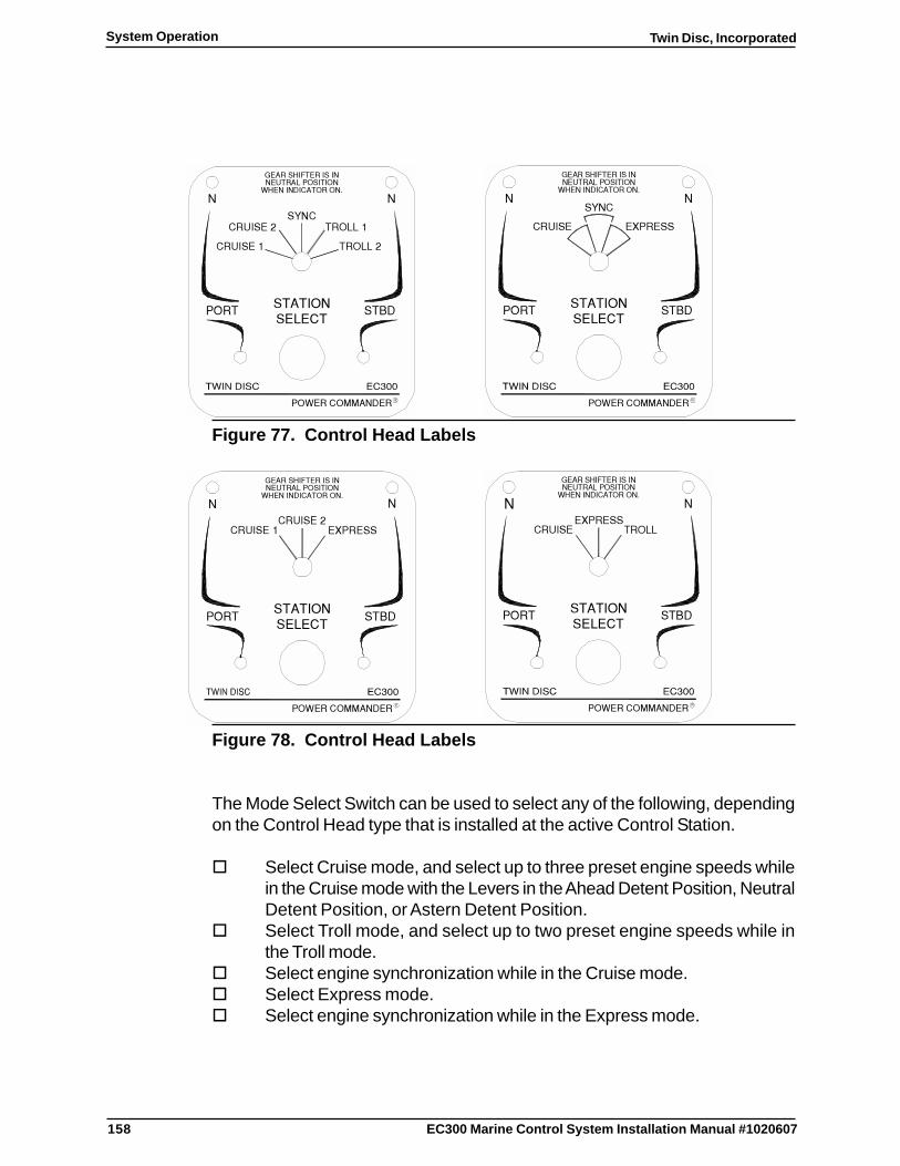
158
Twin Disc, IncorporatedSystem Operation
EC300 Marine Control System Installation Manual #1020607
��������������
��������
����
�
������
����������
�����
����������������
����� ��������
�����������������
��������
� ��
�����
�
��������������
����
�
������
����������
����������������
����� ��������
�����������������
������
����
� �����
�
Figure 77. Control Head Labels
��������������
����
��������
�
�������
���������
�����
����������������
����� ��������
�����������������
��������
�
��������������
����
�
������
����������
�������
����������������
����� ��������
�����������������
������ ���
�
Figure 78. Control Head Labels
The Mode Select Switch can be used to select any of the following, dependingon the Control Head type that is installed at the active Control Station.
� Select Cruise mode, and select up to three preset engine speeds whilein the Cruise mode with the Levers in the Ahead Detent Position, NeutralDetent Position, or Astern Detent Position.
� Select Troll mode, and select up to two preset engine speeds while inthe Troll mode.
� Select engine synchronization while in the Cruise mode.� Select Express mode.� Select engine synchronization while in the Express mode.
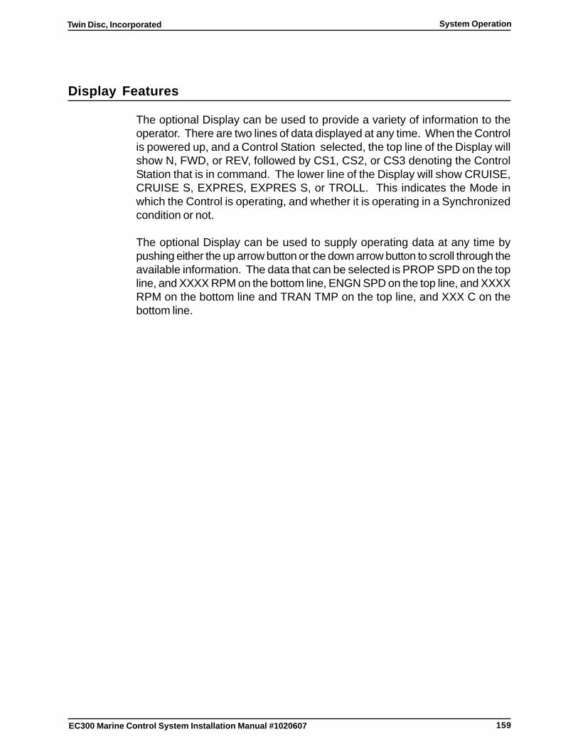
159
Twin Disc, Incorporated System Operation
EC300 Marine Control System Installation Manual #1020607
Display Features
The optional Display can be used to provide a variety of information to theoperator. There are two lines of data displayed at any time. When the Controlis powered up, and a Control Station selected, the top line of the Display willshow N, FWD, or REV, followed by CS1, CS2, or CS3 denoting the ControlStation that is in command. The lower line of the Display will show CRUISE,CRUISE S, EXPRES, EXPRES S, or TROLL. This indicates the Mode inwhich the Control is operating, and whether it is operating in a Synchronizedcondition or not.
The optional Display can be used to supply operating data at any time bypushing either the up arrow button or the down arrow button to scroll through theavailable information. The data that can be selected is PROP SPD on the topline, and XXXX RPM on the bottom line, ENGN SPD on the top line, and XXXXRPM on the bottom line and TRAN TMP on the top line, and XXX C on thebottom line.
160
Twin Disc, IncorporatedSystem Operation
EC300 Marine Control System Installation Manual #1020607
Station Transfer
Station Transfer is accomplished by pressing the Station Select Button on theControl Head.
Station Transfer Types
The EC300 Control System supports several optional types of Station Transfer.Twin Disc Incorporated or the local Technician makes the selection duringConfiguration.
The four major types of Station transfer are discussed in the following sections.
� Instant Station Transfer
� Neutral Station Transfer
� Lever Match Station Transfer
� Lever Match with Acknowledge Station Transfer
161
Twin Disc, Incorporated System Operation
EC300 Marine Control System Installation Manual #1020607
Instant Station Transfer
In this configuration, the station is selected as soon as the Station Select Buttonis pressed. This is regardless of the Lever position on either the active ControlHead or the target Control Head. When the target Control Head is made active,all other Control Heads in the system are made inactive.
If a Station Select Button is depressed at a Control Head other than theactive Control Head, the Controller will respond to the Lever positionsand Mode Select Switch at the newly activated Control Head.Unexpected vessel operation can occur if Lever positions and ModeSelect Switch settings are not in the desired positions prior to takingcommand at a new Control Station.
1. Place all Mode Select Switches and Levers in the desired position atthe desired Control Station.
2. Depress the Station Select Button on the Control Head to take commandat the desired Control Station.
3. Observe that the red Station Select Indicator LED light(s) next to theStation Select Button illuminate.
4. Make other control selections as desired.
Neutral Station Transfer
In this configuration, station transfers are only allowed when the Station SelectButton on the target Control Head is pressed and the Lever(s) on the targetControl Head are in the Neutral Detent Position. If the Station Select Button onthe target Control Head is pressed, and the Lever(s) are not in the NeutralDetent Position, the Station Select Indicator LED’s (lights) on both the activeControl Head and the target Control Head will flash. When the lever(s) on thetarget Control Head are moved to the Neutral Detent Position, the Station SelectIndicator LED’s will stop flashing and the target Control Head will become theactive Control Head. If the Target Control Head Lever(s) are not moved to theNeutral Detent Position within 10 seconds of the request, the station transferrequest shall be cancelled and the Station Select Indicator LED’s will stopflashing. It is important to note that the target Control Station can be selected atany time by two consecutive presses of the Station Select Button to allow ControlStation Transfer during emergency situations.
162
Twin Disc, IncorporatedSystem Operation
EC300 Marine Control System Installation Manual #1020607
Lever Match Station Transfer
This type of station transfer is designed to satisfy certain American Bureau ofShipping (ABS) specification requirements. In this configuration, stationtransfers are only allowed when the levers on the target and active ControlHeads are in matching positions. If the Station Select Button on the targetControl Head is pressed, and the Lever(s) on the target Control Head aremismatched from those on the active control head, the Station Select IndicatorLED’s (lights) on both the active Control Head and the target Control Head willflash. The greater the mismatch, the slower the LED flash rate will be. As theLever(s) on the target Control Head are moved closer to the position of theLever(s) on the active Control Head, the LED flash rate increases. When thelevers are matched, the target Control Head is automatically made active andthe active Control Head made inactive. The Station Select Indicator LED onthe now active Control Head will remain on. If at any time, while a mismatchcondition exists, the Lever(s) on the active Control Head are moved, or if 10seconds pass without the Lever(s) on the target Control Head being moved,the station transfer request shall be cancelled and the Station Select IndicatorLED’s will stop flashing. It is important to note that the target Control Stationcan be selected at any time by two consecutive presses of the Station SelectButton to allow Control Station Transfer during emergency situations.

163
Twin Disc, Incorporated System Operation
EC300 Marine Control System Installation Manual #1020607
Lever Match with Acknowledge Station Transfer
This type of station transfer is designed to satisfy certain ABS specificationrequirements. In this configuration, station transfers are only allowed when thelevers on the target and active control station are in matching positions andwhen the station transfer is acknowledged by the active Control Head.
To initiate a station transfer, a Station Select Button on a Control Head at thetarget station must be pressed. The Station Select Indicator LED’s at both theactive and target stations will begin to flash. This indicates to the active stationthat the target station has requested a transfer. Note: the Neutral Indicator LEDfor any Lever(s) at the active station which are at the neutral detent will alsoflash indicating that the associated transmission is in neutral.
To continue, a Station Select Button on a Control Head at the active stationmust be pressed. This causes the Neutral Indicator LED’s on both stations tobegin to flash, indicating to the target station that the active station hasacknowledged the transfer request.
If the Lever(s) at the active station and the target station are not matched, theStation Select Indicator LED’s and the Neutral Indicator LED’s on both theactive and the target stations will be flashing. As the Lever(s) at the targetstation are moved closer to the position of the Lever(s) at the active station, theflash rate of the LED’s will increase.
When the Lever(s) at the target station match the position of the Lever(s) at theactive station, the Station Select Indicator LED’s at both stations will ceaseflashing and remain on while the Neutral Indicator LED’s at both stations will goto a rapid flash. This indicates to both stations that the Lever(s) are matchedand the transfer may continue.
The transfer is completed when the Station Select Button on a Control Head atthe target control station is pressed. The button press is only recognized if theLever(s) are matched.
If, at anytime, no activity is seen at either station after a transfer has been initiatedfor a period of ten seconds, the transfer sequence will be canceled. Also, if theacknowledge has been made and the Lever(s) on the active control station aremoved, the transfer will be cancel.
It is important to note that the target Control Station can be selected at any timeby two consecutive presses of the Station Select Button to allow Control StationTransfer during emergency situations.

164
Twin Disc, IncorporatedSystem Operation
EC300 Marine Control System Installation Manual #1020607
Manual Mechanical Control
This section addresses mechanical control at the push-pull cable connectionat the engine, transmission, or troll valve in case of electrical or Control Systemfailure. For electronic controls, see the applicable manufacturer’s literature forany suggestions. Some transmissions have a manual gear select capability inaddition to electronic control.
In the event that the Control System becomes inoperative, the push-pull cablesare mechanically and electrically free to move. The throttle, troll, or gear selectlever may be operated manually as required. If the servo actuator is resistingmanual control, unplug the connector at the servo actuator.
If the EC300 Marine Control system is at least partially functioning and a TwinDisc Display is present the Neutral Start Relay can be “forced on” in order tostart the engine. Refer to the Troubleshooting Section for more detailedinformation.
If the EC300 Marine Control System is not functioning, the engine can be startedby placing a jumper between the neutral start interlock pins 9 and 10 in thecable connected to the EC300 Control’s Connector J5. This jumper should beplaced at the engine control if practical. Refer to the engine manufacturer’sdrawings and wiring diagrams.

165
Twin Disc, Incorporated System Operation
EC300 Marine Control System Installation Manual #1020607
Individual Engine Operations
Engine Start
1. At the selected Control Station, place the Lever(s) in the Neutral DetentPosition.
2. Place the ignition switch for the desired engine in the On position asrequired to activate the EC300 Control System.
3. Press and release the Station Select Button on the Control Head.
Note: The red Station Select Indicator LED for the desiredengine must illuminate.
Note: If only one Control is powered up in twin engineinstallations, starting of the second engine will require thatthe Station Select Button be depressed after the secondengine’s ignition switch is turned on.
4. Verify that the red Station Select Indicator LED(s) next to the StationSelect Button is illuminated. This indicates that the station is in command.
5. Start the engine with the ignition switch.
6. Warm the engine using the Mode Select Switch in a higher Cruiseposition, or Direction Disabling ,as required.
166
Twin Disc, IncorporatedSystem Operation
EC300 Marine Control System Installation Manual #1020607
Engine Warm-up while using Direction Disable Mode
Note: The direction disable feature can be used any time thatengine speed above idle is required while keeping thetransmission in neutral. The engine speed can be variedfrom minimum to maximum.
When the Lever is returned to the Neutral Detent Position from theDirection Disable Mode, the Controller will reset and normal operationwill resume. That is, the transmission will shift when the Lever is movedin the Ahead or in the Astern direction without depressing and holdingthe Station Select Button.
1. Depress and hold the Station Select Button while moving the Lever(s) ineither the Ahead or Astern direction.
2. Set the desired engine speed by positioning the Lever(s).
3. When the engine is warm, return the Lever(s) to the Neutral DetentPosition.
Engine Shutdown
1. At the selected Control Station, place the Lever in the Neutral DetentPosition.
2. Place the ignition switch for the engine in the Off position in order to de-energize the EC300 Control System.

167
Twin Disc, Incorporated System Operation
EC300 Marine Control System Installation Manual #1020607
Engine Synchronization
Note: The port most engine is the master. All other engines areslaves.
Synchronization operation in the EC300 Control System has the followingfeatures and characteristics:
� Logically controlled to operate only if all active engines are in CruiseSync or Express Sync mode and Forward (Ahead) direction.
� Automatically turns on if all Levers are moved in the Forward (Ahead)direction and all Mode Select Switches are in the Cruise Sync or ExpressSync position.
� Automatically shuts off if any Lever is moved out of the Forward (Ahead)direction.
� “Authority” is limited to approximately 7 1/2 degrees of the slave’sLever(s) position. A slave Control can add or subtract up to 7 1/2 degreesof lever travel from the engine throttle command received from the mastercontrol.
� Throttles can be used to maneuver the boat without turningsynchronization off. A slave’s engine speed will start to increase ordecrease (depending on the direction of travel) if the slave’s Lever hasleft the 7 1/2 degree synchronization window.
� With the master engine stable, the slave engine(s) will normally bebrought to match the master engine’s speed within 5 rpm in 5 to 10seconds. The timing depends on the differences between engine speedsprior to engaging synchronization.
� Synchronization is deselected by moving the Mode Select Switch out ofthe Cruise Sync or the Express Sync position.

168
Twin Disc, IncorporatedSystem Operation
EC300 Marine Control System Installation Manual #1020607
Synchronizing Engines
Note: Synchronization occurs when all active slave Levers arewithin 7 1/2 degrees (approximately two finger widths) ofthe master Lever.
1. Move all Levers together while setting the master engine to the desiredoperating speed.
2. Move the Mode Select Switch to the Cruise Sync or Express Syncposition on all Control Heads.
Note: The slave engine(s) will increase or decrease speed tomatch the master engine speed each time the masterLever is moved provided each slave’s Lever is within7 1/2 degrees of the master Lever.
3. To slightly change speeds, move the master Lever ensuring that the7 1/2 degree synchronization window is maintained.
4. To significantly change speeds, move all Levers together ensuring thatthe 7 1/2 degree synchronization window is maintained.
Ending Engine Synchronization
1. To end synchronization, do one of the following actions:
� At the selected Control Station, deselect Sync mode.
� Select the Neutral Detent Position or Reverse Detent Positionwith either Lever.
� Move either Lever beyond the 7 1/2 degree limitation in position.
2. Observe that the starboard engine speed no longer follows the portengine speed.
3. Control engine speeds independently using the appropriate Levers.

169
Twin Disc, Incorporated Troubleshooting
EC300 Marine Control System Installation Manual #1020607
Troubleshooting
Introduction
This section includes diagnostic test mode instructions.
Note: The Twin Disc display is required to run these tests.
Note: These tests are also available via the Marine Field SupportTool (MFST).
Diagnostics Test Mode
Diagnostics mode is available for control system tests, and for ease in certaintroubleshooting procedures. These tests verify operation of the control, integrityand function of the external circuits, and provide a means to energize clutchesindividually. They are also helpful in troubleshooting the transmission. Sixteenseparate tests can be individually selected and performed via the display unit.This mode is entered by simultaneously depressing the up and down arrowswitches on the display unit while powering the control by cycling the key switchoff and back on.

170
Twin Disc, IncorporatedTroubleshooting
EC300 Marine Control System Installation Manual # 1020607
Note: The TroubleshootingTesting discussions and charts thatfollow may include selections that do not apply to yourinstallation.
Test 1. Display Test 1 DSPLAY TEST
Upon entering the Troubleshooting Mode, the display test will be enteredautomatically. 1 DSPLAY TEST will appear. After two seconds, all displaysegments/pixels will be displayed. After five seconds, the display will beginalternating between 1 DSPLAY TEST (for one second), all segments/pixels(for one second), and the firmware checksum, CHECKSUM XXXX. Test 1may be exited by depressing either the up or down arrow button. If the downarrow button is pushed, the next display will be 2 POWER TEST. If the uparrow button is pushed, the next display will be 16 FAULT LOG. Subsequentlypushing the up or down arrow button will scroll through the list of possible tests,numbered 1 through 16 (in either direction). When the desired test identifier isdisplayed, the test can be entered by simultaneously depressing the up anddown arrow button.
171
Twin Disc, Incorporated Troubleshooting
EC300 Marine Control System Installation Manual # 1020607
Test 2. Power Supply Test 2 POWER TEST
The following sub-menu items will be displayed: SUPPLY VOLTAGE,REFERENC VOLTAGE, INTERNAL POWER, EXIT TEST. These arescrolled through by depressing the up or down arrow button. To enter one ofthe tests, simultaneously depress both the up and down arrow button. Onceentered, the sub menu test may be exited by pushing the up arrow button.
SUPPLY VOLTAGE will display the voltage level that is supplied to the primaryand auxiliary power input pins on the controller. Note that connecting voltage tothe auxiliary pins is optional. The display will show P:XX.XXV A:YY.YYV,where XX.XX is the voltage on the primary power input, and YY.YY is thevoltage on the auxiliary power unit. Below 8 volts will indicate a blank display,and above 50 volts, the display will flash 50.00 V.
Note: Both primary and auxilliary supply must be less than 32.0VDC. Both primary and auxiliary supply must be greaterthan 10.1 VDC.
REFERENC VOLTAGE will display the measured reference voltage for theanalog to digital converter. If the voltage is not 2.50 V +/- 50 mv, the controlcannot reliably measure any analog signal. The display will show REF X.XX Vwhere X.XX is the reference voltage.
INTERNAL POWER is a scan test of the other internal power supply nodes,and reports any nodes that measure outside of preset limits. Upon successfulcompletion of this scan, the display will show TEST PASSED. If any voltagesare out of range, the display will indicate the voltage name and the word FAILED.The internal voltage names are: REF, VSUST, OVR POW, XITE. The controlmust be replaced if one of these voltages are failed, and the proper voltage isbeing supplied to the Control.
EXIT TEST will return the control to the main menu at the same point that it waswhen the test was entered.
172
Twin Disc, IncorporatedTroubleshooting
EC300 Marine Control System Installation Manual # 1020607
Test 3. Station Test 3 STATN TEST
This test allows inspection of the three control station ports on the control. Uponentering this test, STATION1, STATION2, STATION3, or EXIT TEST can beselected. When a station is selected, the following sub-menu can be scrolledthrough: LeverCal, LEVER, MODE, POS VOLT, STAT SEL, POS CUR, REVSWCH, FWD SWCH, NEU LITE, EXIT SUB. Each individual test can beentered by simultaneously depressing the up and down arrow buttons.
Upon entering LeverCal, a sequential sub-menu appears as follows: FULLFWD, DET FWD, FULL REV, DET REV. Each position also displays XXXXmV, indicating the voltage level at the lever position. Each position must beselected for calibration or skipped for the next selection to appear. The levercan be calibrated by placing the Lever in the position indicated, andsimultaneously depressing the up and down arrow buttons. In each position,as both buttons are depressed, the message CalPoint SAVED will bemomentarily displayed. If only the up arrow button is pressed, the messageCalPoint SKIPPED will be momentarily displayed before the next selection isdisplayed. DEFAULT USED means the lever voltage was outside of theexpected range. Lever calibration requires saving the value at each of the fourpositions in the order listed. After all four positions have been calibrated, thedisplay returns to the sub-menu.
Upon entering LEVER, LEVER X.XXV is displayed. Momentarily pressingthe down arrow button will display LEVER YY.Y%, where X.XX or YY.Y is theLever position in volts or percent. These displays will alternately be displayedeach time the down arrow button is pressed.
Upon entering MODE, the display will show the voltage that represents theposition that the Mode Select Switch is in. Momentarily pressing the downarrow button will display the position that the Mode Select Switch is in. Thepositions listed will depend on the Control Head Type that is installed. OneControl Head is used here as an example. Repetitively pressing the downarrow button will cause the display to alternate between two screens, such asMODE CRUISE and MODE X.XXV. Other alternating displays with the ModeSelect Switch in other positions may include MODE CSYNC and MODEX.XXV, MODE ESYNC and MODE X.XXV, MODE EXPRESS and MODEX.XXV, MODE TROLL and MODE X.XXV, where X.XX is the voltage level.
Upon entering POS VOLT, +X.XXV will be displayed where X.XX is the voltagelevel.
Upon entering STAT SEL, STAT SEL X.XXV will be displayed. Repetitivelypressing the down arrow button will cause the display to alternate betweenSTAT SEL X.XXV and STAT SEL St1-PORT(OR STBD), where X.XX is the
173
Twin Disc, Incorporated Troubleshooting
EC300 Marine Control System Installation Manual # 1020607
voltage level, and PORT or STBD will depend on which controller is beingtested.
Upon entering POS CUR, +XXmA will be displayed where XX is the CURRENTlevel.
Upon entering REV SWCH, CLOSED or OPEN will be displayed, indicatingwhether the lever is in the reverse position or not.
Upon entering FWD SWCH, CLOSED or OPEN will be displayed, indicatingwhether the lever is in the forward position or not.
Upon entering NEU LITE, OFF or ON can be toggled with the use of the downarrow button. The Neutral position light will be turned on and off.
To exit the sub-menu, momentarily depress the up and down arrow buttonsimultaneously while EXIT SUB is displayed. The test can be repeated for theother stations.
174
Twin Disc, IncorporatedTroubleshooting
EC300 Marine Control System Installation Manual # 1020607
Test 4. Discrete Switch Test 4 SWITCH TEST
This test shows the status of the selected switches that are enabled on yourinstallation. Upon entering this test, SHFT BRK STATUS, OIL PRES STATUS,OIL FILT STATUS, LVR ENB STATUS, DiagBoot STATUS, or EXIT TESTcan be scrolled through with the use of the up or down arrow buttons. Thedisplayed status is either OPEN or CLOSED.
SHFT BRK STATUS = Shaft Brake Switch Status
OIL PRES STATUS = Oil Pressure Switch Status
OIL FILT STATUS = Oil Filter Differential PressureSwitch Status
LVR ENB STATUS = Lever Function Switch Status
DiagBoot STATUS = Diagnostic Boot Switch Status(Not for Customer Use)
175
Twin Disc, Incorporated Troubleshooting
EC300 Marine Control System Installation Manual # 1020607
Test 5. Boundary Scan Test 5 SCAN TEST
CAUTIONThe engine must not be running when entering this test. If the engine isrunning, severe transmission and engine damage can result.
Two options will be displayed on the sub-menu: RUN TEST and EXIT TEST.Upon selecting RUN TEST, the control will automatically check all speed sensorand coil circuits for continuity and miscellaneous sensors to verify that the signalis in the proper range. The display will show TESTING, followed by TESTPASSED if all functions are normal. Depressing the up arrow button willterminate the test and display EXIT TEST. If a fault is detected in a speedsensor circuit, the top half of the display will indicate which sensor is beingtested, and the bottom half of the display will indicate the fault condition found.Pressing the up arrow button will allow the test to resume from that positiion,and continue until all sensors have been tested. EXIT TEST will then bedisplayed. The speeds tested are PROP SPD and ENGN SPD. The coilstested are FWD, REV, NEUTRAL, TROLL, and SHFT BRK.

176
Twin Disc, IncorporatedTroubleshooting
EC300 Marine Control System Installation Manual # 1020607
Test 6. Speed Read Test 6 SPEED RD TEST
The transmission input speed (ENG SPD), transmission output speed (PROPSPD), and EXIT TEST can be displayed during this test. The choices aredisplayed on the first line of the display, and the appropriate data is shown onthe second line. The speed data will be displayed as XXXX RPM. The displaywill blink if the speed is above 9999 RPM. The display will show 0 RPM whenthe frequency is below 40 hz. The data value will be displayed until the up ordown arrow button is pressed, and when EXIT TEST is selected, the control isreturned to the main menu.
Test 7. Sensor Test 7 SENSOR RD TEST
This test allows the operator to view the data generated by the oil temperaturesensor (OIL TEMP), and the internal temperature sensor (INT TEMP). Whenselected, the value is listed on the lower line as SXXX °C. The S stands for thesign of the number, and XXX is the current temperature in degrees Celsius.The data value will be displayed until the up or down arrow button is pressed,and when EXIT TEST is selected, the control is returned to the main menu.

177
Twin Disc, Incorporated Troubleshooting
EC300 Marine Control System Installation Manual # 1020607
Test 8. Coil Test 8 COIL TEST
Upon entering this test, FWD, REV, SHFT BRK, TROLL, NEUTRAL, andEXIT TEST can be selected (depending on the software configuration).
After selection of an individual coil, a sub menu will be displayed, showing thefollowing options: FULL ON, MODULATE, PRESET, and EXIT SUB MENU.
If FULL ON is selected, the selected coil will be powered with full on current.The display will show the coil selected and display FULL ON. Depressing theup arrow button will turn the coil off and go back to the sub menu.
If MODULATE is selected, the selected coil can be toggled on in increments of5% of full current with the use of the up arrow button. It can be reduced inincrements of 5% of full current with the use of the down arrow button. Thedisplay will identify the coil selected, the percentage of full current, and thecurrent value. (Example: FWD 55% .13A) The test can be terminated byreaching 100% and pressing the up arrow button again, or by simultaneouslydepressing both the up and down arrow buttons at any time. These actions willboth result in EXIT SUB MENU being displayed.
If PRESET is selected, current to the selected coil will be ramped linearly fromzero to full current in 7.5 seconds, and then from full current to zero current overthe next 7.5 seconds. This cycle will be continuously repeated until the up arrowbutton is pushed. This will turn the current to zero, and return the control to thesub menu listing the choices. While the cycling is continuing, the display willidentify the coil, the percentage of full current, and the current level.
Test 9. Communication Tests 9 COMM TESTS
This test may be used to confirm the functionality of an externally installed RS232communication link. This test requires special test harnesses, and is only usedby qualified electronic technicians. Listed selections are RS232, Address,RS485, and EXIT TEST. If RS232 is entered, and proper connections aremade, the message BAD LINK CONNECT Rx TO Tx or WORKING will bedisplayed. If Address is entered, the address of the communication port willbe displayed as Address PORT Y-XX, STBD Y-XX, or INVALID, where Y is0,1,2, or 3, and XX is 00, 01, 10, 11, 20, 21, 30, or 31. If RS485 is entered, themessage RS485 WORKING or RS485 BAD LINK will be displayed.
178
Twin Disc, IncorporatedTroubleshooting
EC300 Marine Control System Installation Manual # 1020607
Test 10. Speed Out Test 10 SPEED OUT TEST
This test allows the operator to generate a frequency via the control to test thevessel’s tachometer readout. Upon entering the test, TACH HZ and EXIT TESTwill be displayed. If TACH HZ is selected, the display will show TACH HZ onthe top line, and 0500 on the bottom line with the right most digit flashing toindicate it is selected for change. The flashing digit can be changed by usingthe up arrow. The other digits can be selected by using the down arrow. Afrequency will be generated and sent to the tachometer output until the test isexited by simultaneously depressing the up and down arrow buttons.
Test 11. Warranty Date and Software/Hardware Version 11 VERSNWARRANTY
Four sub-menu items are available during this test: SOFTWARE VERSION,HARDWARE VERSION, WARRANTY DATE, and EXIT TEST. IfSOFTWARE VERSION or HARDWARE VERSION are selected, the partnumber and the version will be displayed. Depressing the up arrow button willresult in the sub menu again being displayed. If WARRANTY DATE is selected,the date shall be taken from memory and displayed as DDMMMYY. If thewarranty has not been initialized, it will display NOT STARTED.
Test 12. Adjust Display 12 ADJST DISPLAY
Four sub menu items are available during this test: ADJUST BACKLITE,ADJUST CONTRAST, FACTORY DEFAULT, and EXIT TEST.If ADJUST BACKLITE is selected, three options are ADJUST BRITENES,SET MIN VALUE, and EXIT SUB MENU. If ADJUST BRITENES is selected,the display will indicate ADJUST NOW, and the brightness level can be adjustedby the up and down arrow buttons. The SET MIN VALUE will apply the lowestallowable setting to the brightness. EXIT SUB MENU will again display thefirst sub menu options.Selecting ADJUST CONTRAST will display ADJUST NOW, and allow thecontrast to be adjusted by the up or down arrow buttons. Simultaneouslydepressing the up and down arrow buttons will display the first sub menu options.Selecting FACTORY DEFAULT will return the brightness and contrast to thefactory default condition. The message, WORKING, will be displayed for twoseconds to indicate that the action is complete. After FACTORY DEFAULT isagain displayed, the test can be exited by simultaneously depressing the upand down arrow button, and then selecting EXIT TEST.
179
Twin Disc, Incorporated Troubleshooting
EC300 Marine Control System Installation Manual # 1020607
Test 13. Servo Test 13 SERVO TEST
This test will allow the operator to test the Servo Power driver and the servoposition. Upon entering the test, the display will show TEST SERVO or EXITTEST. If TEST SERVO is selected, the control will turn on the Servo Powerdriver, and OVER CURRENT or SERVO XXX% will be displayed.If SERVO XXX% is displayed, the right most digit will flash to indicate it isselected for change. The flashing digit can be changed by using the up arrow.The other digits can be selected by using the down arrow. The Servo will bepositioned to the percentage of full rotation that is shown on the display. Pressboth the up and down arrow buttons simultaneously to set the servo output tozero, turn the Servo Power driver off, and exit.If OVER CURRENT is displayed, the Servo Power driver experienced an overcurrent condition and was turned off. Press both the up and down arrow buttonssimultaneously to turn the Servo Power driver off, reset the fault detection circuitryand exit to the Servo Test menu.
Test 14. Control Outputs 14 SWTCH OUTPUTS
This test allows the operator to select certain outputs that are a part of thecontrol system, and turn them on or off as desired. ALM DRV, NEUT RLY, orEXIT TEST can be selected. If a switch or relay is present and selected, thedisplay can be toggled between the open and closed condition, such asALMDRV OPEN, and ALMDRV CLOSED, by pressing the down arrow button.Press the up arrow button to exit.

180
Twin Disc, IncorporatedTroubleshooting
EC300 Marine Control System Installation Manual # 1020607
Test 15. Engine Throttle 15 ENGIN THROTTLE
This test allows the operator to manipulate the throttle output. Upon entering,TEST THROTTLE, or EXIT TEST can be selected. If TEST THROTTLE isselected, THROTTLE will be displayed on the top line, and XX% will bedisplayed on the bottom line with the right most digit flashing, indicating that itis ready for changing. Pressing the up arrow will increment the flashing digit.Pressing the down arrow will move the selected digit one to the left. The throttlewill be set to the value shown. Pressing both buttons simultaneously will resetthe value to zero and exit the test. If, upon entering the TEST THROTTLE, aproblem exists, the message ThrotPwr FAULT will be displayed.
181
Twin Disc, Incorporated Troubleshooting
EC300 Marine Control System Installation Manual # 1020607
Test 16. Fault Log 16 FAULT LOG
This test gives limited access to the Fault Log Memory with the date and timeof occurrences of logged fault messages. The following are the sub menuchoices with a description of the contents. Note: The acronym NVM refersto the Non Volatile Memory in the control.
ALL FAULTS = Record of all faults written to NVM
SPEED = Record of Speed Sensor faults written to NVMSENSORS
TEMP SENSORS = Record of Temperature Sensor Signal faults writtento NVM
STATION = Record of Station faults written to NVM
LEVER = Record of Lever faults written to NVM
SWITCHES = Record of Discrete Switch faults written to NVM
COILS = Record of Coil Driver faults written to NVM
POWER = Record of Power Supply faults written to NVMSUPPLIES
INTERNAL = Record of Internal Controller faults written to NVMFAULTS
COMM FAULTS = Record of Communication faults written to NVM
EXIT TEST = Exit to Main Menu
182
Twin Disc, IncorporatedTroubleshooting
EC300 Marine Control System Installation Manual # 1020607
When any selection is made other than EXIT TEST, the sub menu of SHORTLOG LIST, LONG LOG LIST, and EXIT SUB MENU will be displayed.
Selecting the SHORT LOG LIST will allow scrolling (by using the up and downarrow buttons) through any faults that have been logged into memory since thememory was last cleared. The logged code, date, and time for any faults loggedfor the category selected will be displayed, followed by the message END OFLOG. If no messages have been logged, the message NO LOG FAULTS willbe displayed. The short log list can be cleared by depressing and holding theup arrow button for six seconds when at the beginning of the fault list. If this isdone, the message CLEARING SHORT LG will be displayed while the clearingis occurring. Once cleared, the message NO LOG FAULTS will appear.
Selecting the LONG LOG LIST will allow scrolling through any faults that hadbeen logged into memory (by using the up and down arrow buttons). Thelogged code, date, and time for any faults logged for the category selected willbe displayed, followed by the message END OF LOG. This list of faults cannot be cleared. If the allocated memory capacity is exceeded, the “first in”faults will be overwritten. If no faults have occurred, NO LOG FAULTS will bedisplayed. Simultaneously depressing both up and down arrow buttons willexit the list, and EXIT SUB MENU must be selected to return to the main menu.Selecting EXIT TEST will return the control to the main menu.
Exit Test Mode
Exit the Test Mode by cycling the key switch off and back on.
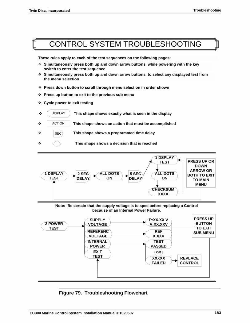
183
Twin Disc, Incorporated Troubleshooting
EC300 Marine Control System Installation Manual # 1020607
CONTROL SYSTEM TROUBLESHOOTING
PRESS UP ORDOWN
ARROW ORBOTH TO EXIT
TO MAINMENU
These rules apply to each of the test sequences on the following pages:
� Simultaneously press both up and down arrow buttons while powering with the keyswitch to enter the test sequence
� Simultaneously press both up and down arrow buttons to select any displayed test fromthe menu selection
� This shape shows exactly what is seen in the display
ACTION� This shape shows an action that must be accomplished
SEC� This shape shows a programmed time delay
� Press down button to scroll through menu selection in order shown
� Cycle power to exit testing
2 SECDELAY
5 SECDELAY
PRESS UPBUTTONTO EXIT
SUB MENU
SUPPLYVOLTAGE2 POWER
TESTREFERENCVOLTAGE
P:XX.XX VA:XX.XXV
TESTPASSED
XXXXXFAILED
DISPLAY
CHECKSUMXXXX
ALL DOTSON
1 DSPLAYTEST
ALL DOTSON
1 DSPLAYTEST
OR
� This shape shows a decision that is reached
EXITTEST
INTERNALPOWER
REFX.XXV
Note: Be certain that the supply voltage is to spec before replacing a Controlbecause of an Internal Power Failure.
� Press up button to exit to the previous sub menu
REPLACECONTROL
Figure 79. Troubleshooting Flowchart
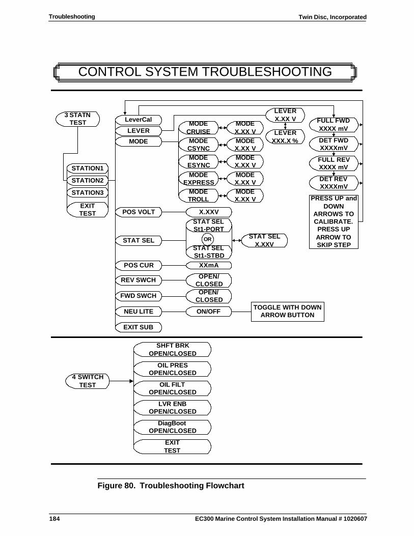
184
Twin Disc, IncorporatedTroubleshooting
EC300 Marine Control System Installation Manual # 1020607
CONTROL SYSTEM TROUBLESHOOTING
3 STATNTEST
EXITTEST
LVR ENBOPEN/CLOSED
4 SWITCHTEST
DiagBootOPEN/CLOSED
STATION3
STATION2
STATION1
FWD SWCH
EXIT SUB
NEU LITE
REV SWCH
POS CUR
POS VOLT
STAT SEL
MODE
LEVER
LeverCal
DET REVXXXXmV
FULL REVXXXX mV
DET FWDXXXXmV
FULL FWDXXXX mV
LEVERXXX.X %
LEVERX.XX V
MODECRUISEMODECSYNC
MODETROLL
MODEEXPRESS
MODEESYNC
OPEN/CLOSED
ON/OFF
STAT SELSt1-PORT
XXmA
OPEN/CLOSED
X.XXVEXITTEST
PRESS UP andDOWN
ARROWS TOCALIBRATE.PRESS UPARROW TOSKIP STEP
MODEX.XX VMODEX.XX V
MODEX.XX V
MODEX.XX V
MODEX.XX V
STAT SELX.XXVSTAT SEL
St1-STBD
OR
TOGGLE WITH DOWNARROW BUTTON
OIL FILTOPEN/CLOSED
SHFT BRKOPEN/CLOSED
OIL PRESOPEN/CLOSED
Figure 80. Troubleshooting Flowchart
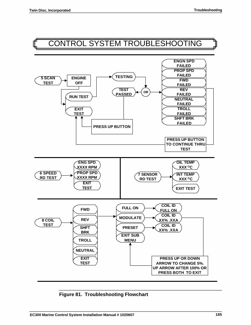
185
Twin Disc, Incorporated Troubleshooting
EC300 Marine Control System Installation Manual # 1020607
CONTROL SYSTEM TROUBLESHOOTING
EXITTEST
RUN TEST
5 SCANTEST
ENGINEOFF
TESTING
ENGN SPDFAILED
PROP SPDFAILED
FWDFAILED
TROLLFAILED
TESTPASSED
OR
PRESS UP BUTTON
PRESS UP BUTTONTO CONTINUE THRU
TEST
REVFAILED
NEUTRALFAILED
6 SPEEDRD TEST
EXITTEST
ENG SPDXXXX RPMPROP SPDXXXX RPM
7 SENSORRD TEST
EXIT TEST
INT TEMPXXX OC
OIL TEMPXXX OC
FWD
8 COILTEST
FULL ON
EXIT SUBMENU
PRESET
MODULATE
COIL IDXX% .XXA
COIL IDXX% .XXA
COIL IDFULL ON
PRESS UP OR DOWNARROW TO CHANGE 5%.
UP ARROW AFTER 100% ORPRESS BOTH TO EXIT
REV
SHFT BRKFAILED
SHFTBRK
NEUTRAL
TROLL
EXITTEST
Figure 81. Troubleshooting Flowchart
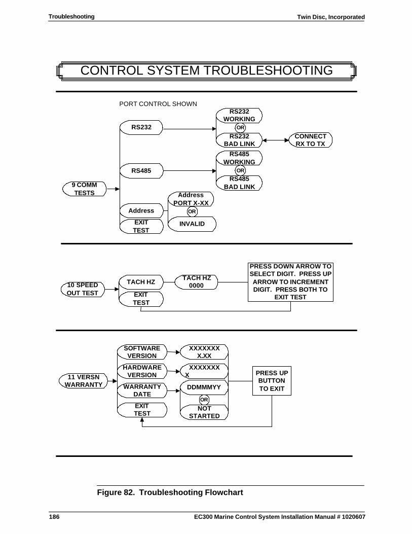
186
Twin Disc, IncorporatedTroubleshooting
EC300 Marine Control System Installation Manual # 1020607
CONTROL SYSTEM TROUBLESHOOTING
9 COMMTESTS
RS485
RS232CONNECTRX TO TX
Address
TACH HZ000010 SPEED
OUT TEST
PRESS DOWN ARROW TOSELECT DIGIT. PRESS UPARROW TO INCREMENTDIGIT. PRESS BOTH TO
EXIT TEST
AddressPORT X-XX
PORT CONTROL SHOWN
TACH HZ
EXITTEST
11 VERSNWARRANTY
EXITTEST
WARRANTYDATE
HARDWAREVERSION
SOFTWAREVERSION
NOTSTARTED
DDMMMYY
XXXXXXXX
OR
PRESS UPBUTTONTO EXIT
XXXXXXXX.XX
INVALID
OR
EXITTEST
RS232WORKING
RS232BAD LINK
OR
RS485WORKING
RS485BAD LINK
OR
Figure 82. Troubleshooting Flowchart
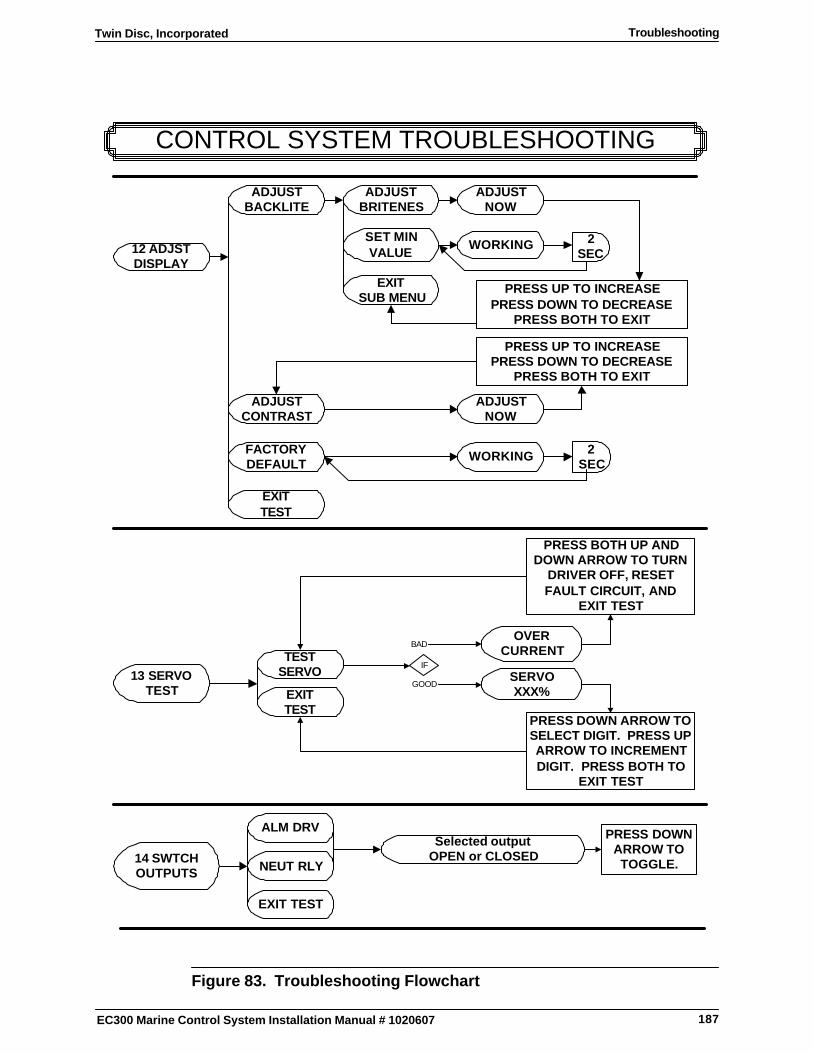
187
Twin Disc, Incorporated Troubleshooting
EC300 Marine Control System Installation Manual # 1020607
CONTROL SYSTEM TROUBLESHOOTING
EXITTEST
13 SERVOTEST
OVERCURRENTTEST
SERVO SERVOXXX%
ALM DRV
14 SWTCHOUTPUTS
Selected outputOPEN or CLOSED
NEUT RLY
PRESS DOWNARROW TOTOGGLE.
EXIT TEST
IF
GOOD
BAD
PRESS DOWN ARROW TOSELECT DIGIT. PRESS UPARROW TO INCREMENTDIGIT. PRESS BOTH TO
EXIT TEST
PRESS BOTH UP ANDDOWN ARROW TO TURN
DRIVER OFF, RESETFAULT CIRCUIT, AND
EXIT TEST
2SEC
2SEC
PRESS UP TO INCREASEPRESS DOWN TO DECREASE
PRESS BOTH TO EXIT
12 ADJSTDISPLAY
ADJUSTBRITENES
EXITTEST
FACTORYDEFAULT
ADJUSTCONTRAST
ADJUSTBACKLITE
WORKING
ADJUSTNOW
WORKING
ADJUSTNOW
EXIT SUB MENU
SET MINVALUE
PRESS UP TO INCREASEPRESS DOWN TO DECREASE
PRESS BOTH TO EXIT
Figure 83. Troubleshooting Flowchart
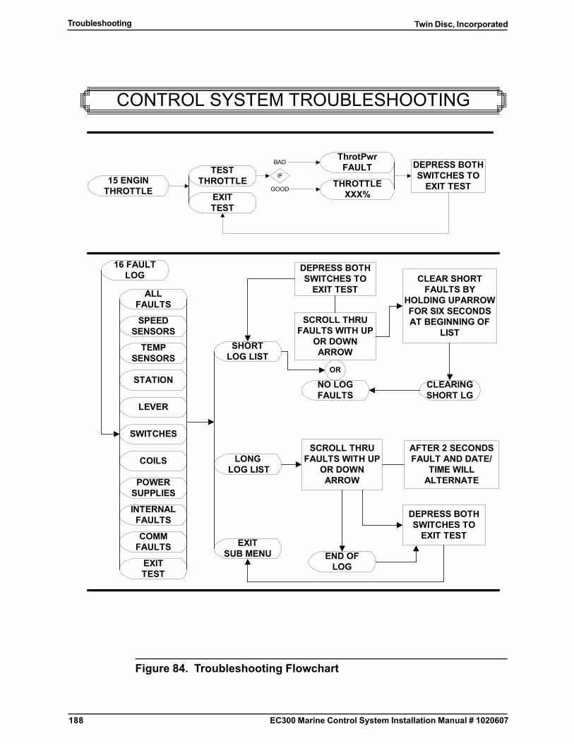
188
Twin Disc, IncorporatedTroubleshooting
EC300 Marine Control System Installation Manual # 1020607
CONTROL SYSTEM TROUBLESHOOTING
LONG LOG LIST
SHORTLOG LIST
16 FAULTLOG
EXITTEST
COMMFAULTS
INTERNALFAULTS
POWERSUPPLIES
COILS
SWITCHES
ALLFAULTS
LEVER
STATION
TEMPSENSORS
SPEEDSENSORS
EXITSUB MENU
CLEARINGSHORT LG
END OFLOG
NO LOGFAULTS
OR
SCROLL THRUFAULTS WITH UP
OR DOWNARROW
DEPRESS BOTHSWITCHES TO
EXIT TESTCLEAR SHORT
FAULTS BYHOLDING UPARROWFOR SIX SECONDSAT BEGINNING OF
LIST
SCROLL THRUFAULTS WITH UP
OR DOWNARROW
DEPRESS BOTHSWITCHES TO
EXIT TEST
AFTER 2 SECONDSFAULT AND DATE/
TIME WILLALTERNATE
15 ENGINTHROTTLE
TESTTHROTTLE
EXITTEST
ThrotPwrFAULT
IFTHROTTLE
XXX%GOOD
BAD DEPRESS BOTHSWITCHES TO
EXIT TEST
Figure 84. Troubleshooting Flowchart

189
Twin Disc, Incorporated
EC300 Marine Control System Installation Manual #1020607
Preventative Maintenance
Preventative Maintenance
Periodic Visual Inspection
Check all electrical wiring, components (switches, magnetic pickups, etc.) andconnections for security, chafing and/or other damage. Tighten looseconnections and replace any damaged parts. Reroute or otherwise securewiring to prevent chafing damage.
Control Cables and Wiring
Inspect and care for control cables and harnesses as follows:
1. Check that cables and/or harnesses are away from hot surfaces, movingparts and oil locations.
2. Check that circular connectors are hand tight.
3. Inspect connectors for damage or defects. For example: bent pins,pushed-back sockets, broken keys, etc.
4. Check the cable and/or harness tie downs. Keep cable securelyfastened.
5. Check the condition of the cables and/or harnesses at any rub points.
6. Check cables and/or harnesses for cracks, effects of vibration, abrasion,brittleness or abuse.

190
Twin Disc, Incorporated
EC300 Marine Control System Installation Manual #1020607
Preventative Maintenance
Control Head
Chrome plated Control Heads should be polished periodically using a chromepolish.
Control
Inspect mounting points for security and damage. Re-torque any loose mountingbolts. Confirm security of bond wire ring lug.
Check that Control is not mounted where it may be subject to significant heat orvibration.
Station Doubler
Inspect mounting points for security and damage. Re-torque any loose mountingbolts. Confirm security of bond wire ring lug.
Check that Station Doubler is not mounted where it may be subject to significantheat or vibration.
Servo Actuator
Inspect and correct any damage or concerns in the following:
� Mounting points� Bond wire� Heat/ vibration related distress� Push/pull Cables� Actuator arm and cable ends
191
Twin Disc, Incorporated Engineering Drawings
EC300 Marine Control System Installation Manual #1020607
Engineering Drawings
List of Engineering Drawings
The following pages include the generic engineering drawings that areapplicable to the EC300 Control System. These generic drawings are listedbelow. Application specific drawings may also be applicable if they are suppliedseparately.
Note: Any part numbers listed in the following engineeringdrawings are for reference only. Please refer to your billof materials for part numbers specific to your application.
� Morse 33 Series Cable MountingDimensions
� 1020676 EC300 Control Mounting DimensionsSheet 1
� 1020676 EC300 Control Mounting DimensionsSheet 2
� Servo Actuator Mounting Dimensions
� 1018791 Twin Disc Display Mounting Dimensions
� EX8892 Generic Interconnection and WiringDiagrams Sheet 1
� EX8892 Generic Interconnection and WiringDiagrams Sheet 2
� EX8892 Generic Interconnection and WiringDiagrams Sheet 3
� EX8892 Generic Interconnection and WiringDiagrams Sheet 4

192
Twin Disc, IncorporatedEngineering Drawings
EC300 Marine Control System Installation Manual #1020607
� Control Head Mounting Template
� Interface Assembly Mounting Template
� Selector Assembly Mounting Template
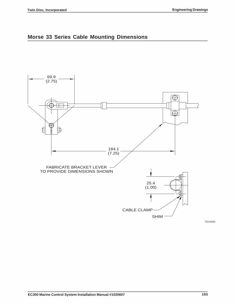
193
Twin Disc, Incorporated Engineering Drawings
EC300 Marine Control System Installation Manual #1020607
Morse 33 Series Cable Mounting Dimensions
69.9(2.75)
184.1(7.25)
25.4(1.00)
CABLE CLAMP
SHIM
FABRICATE BRACKET LEVERTO PROVIDE DIMENSIONS SHOWN
TD10005
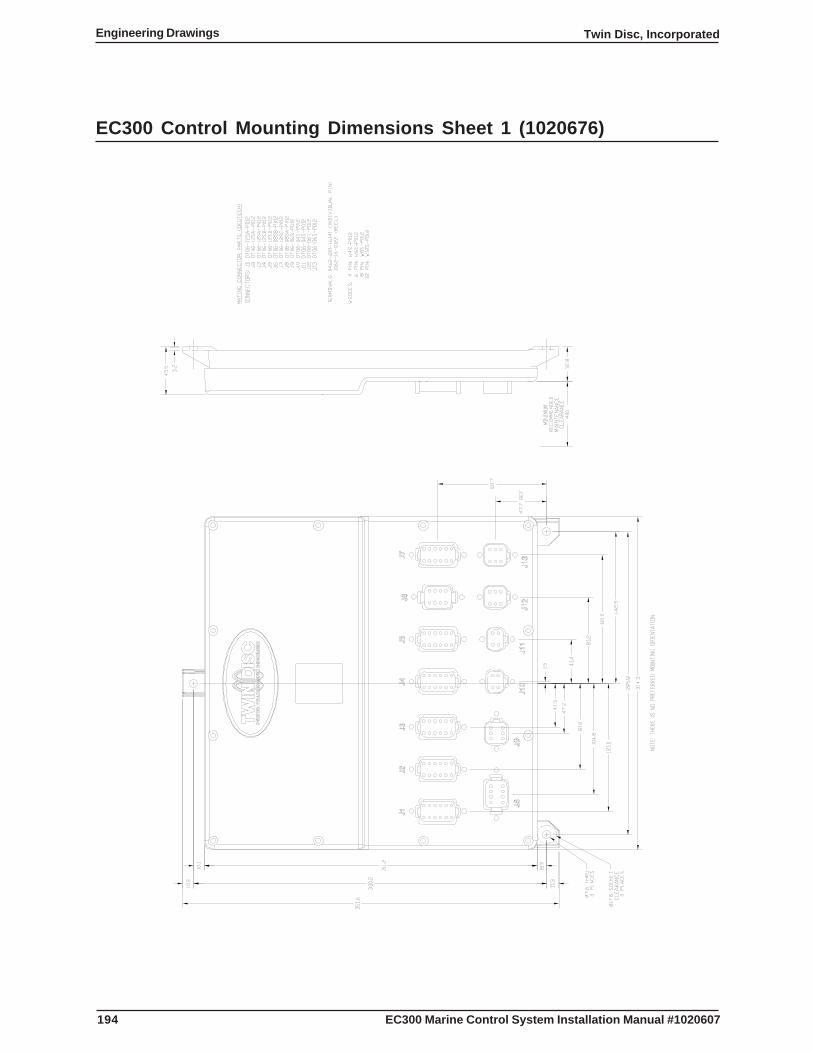
194
Twin Disc, IncorporatedEngineering Drawings
EC300 Marine Control System Installation Manual #1020607
EC300 Control Mounting Dimensions Sheet 1 (1020676)
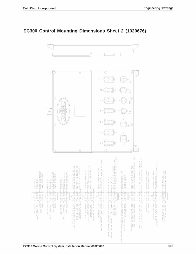
195
Twin Disc, Incorporated Engineering Drawings
EC300 Marine Control System Installation Manual #1020607
EC300 Control Mounting Dimensions Sheet 2 (1020676)
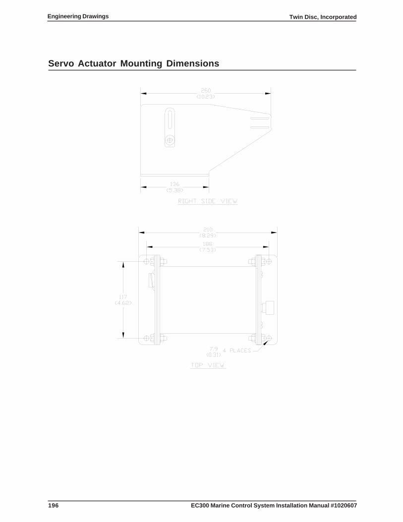
196
Twin Disc, IncorporatedEngineering Drawings
EC300 Marine Control System Installation Manual #1020607
Servo Actuator Mounting Dimensions
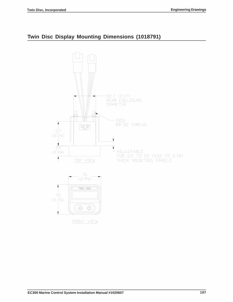
197
Twin Disc, Incorporated Engineering Drawings
EC300 Marine Control System Installation Manual #1020607
Twin Disc Display Mounting Dimensions (1018791)

198
Twin Disc, IncorporatedEngineering Drawings
EC300 Marine Control System Installation Manual #1020607
This page intentionally blank
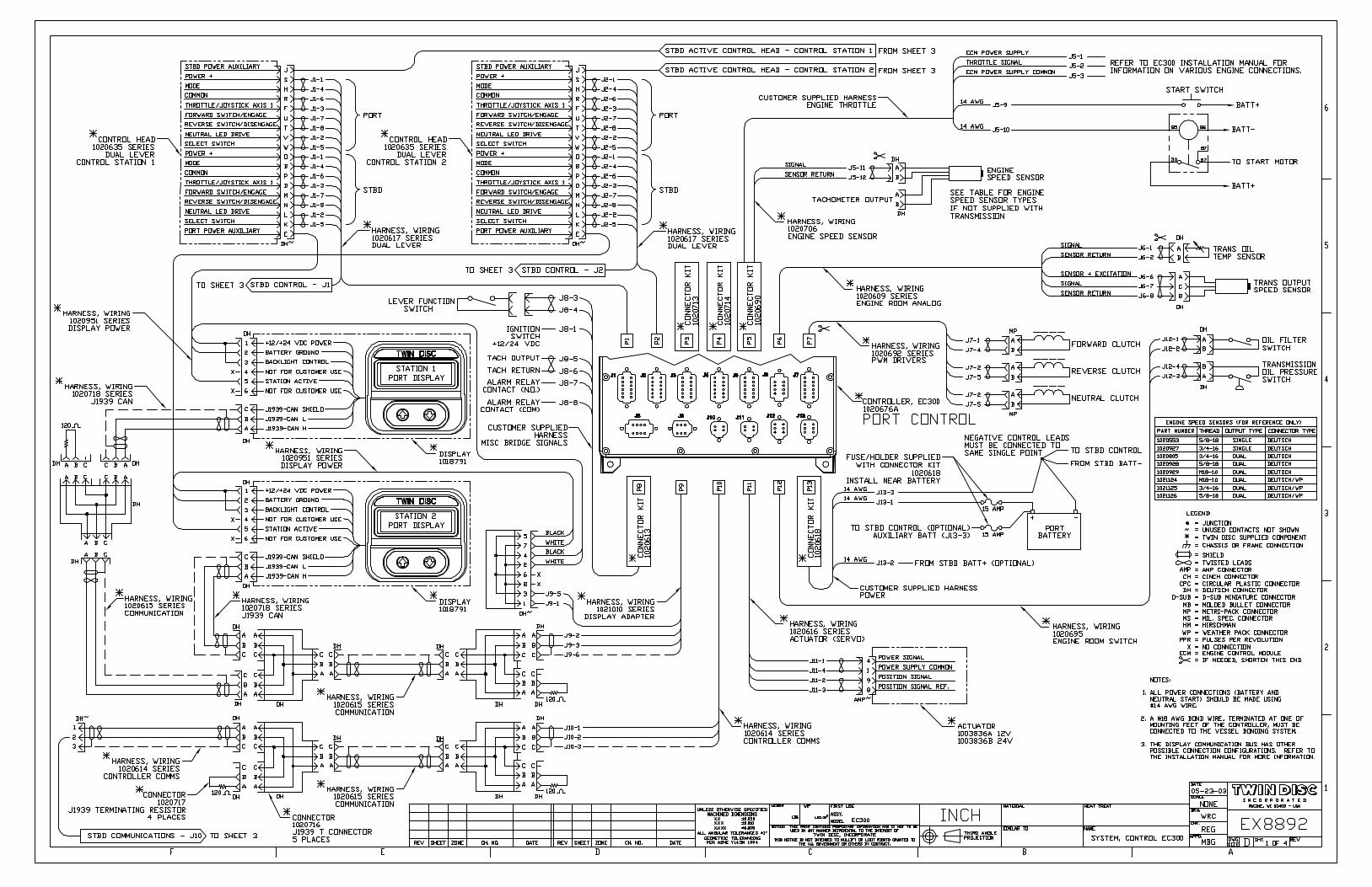

200
Twin Disc, IncorporatedEngineering Drawings
EC300 Marine Control System Installation Manual #1020607
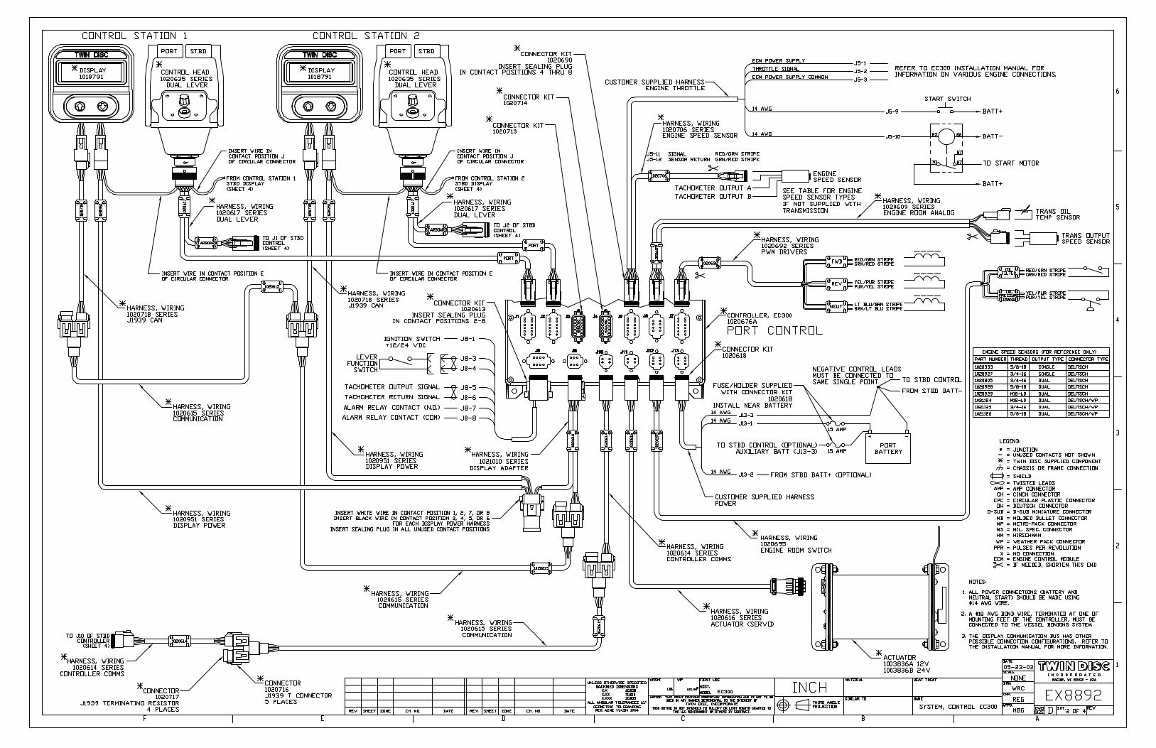

202
Twin Disc, IncorporatedEngineering Drawings
EC300 Marine Control System Installation Manual #1020607
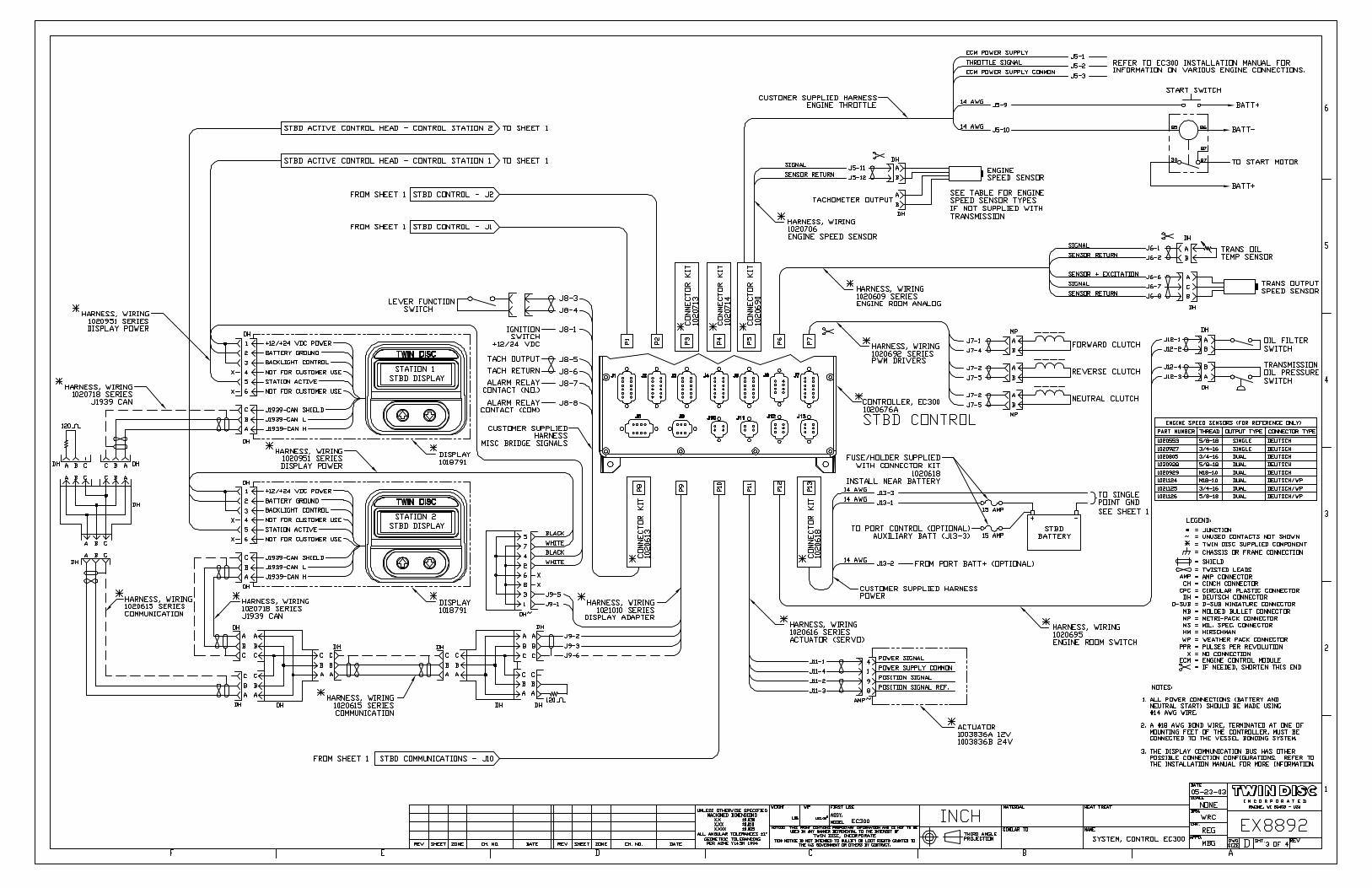

204
Twin Disc, IncorporatedEngineering Drawings
EC300 Marine Control System Installation Manual #1020607
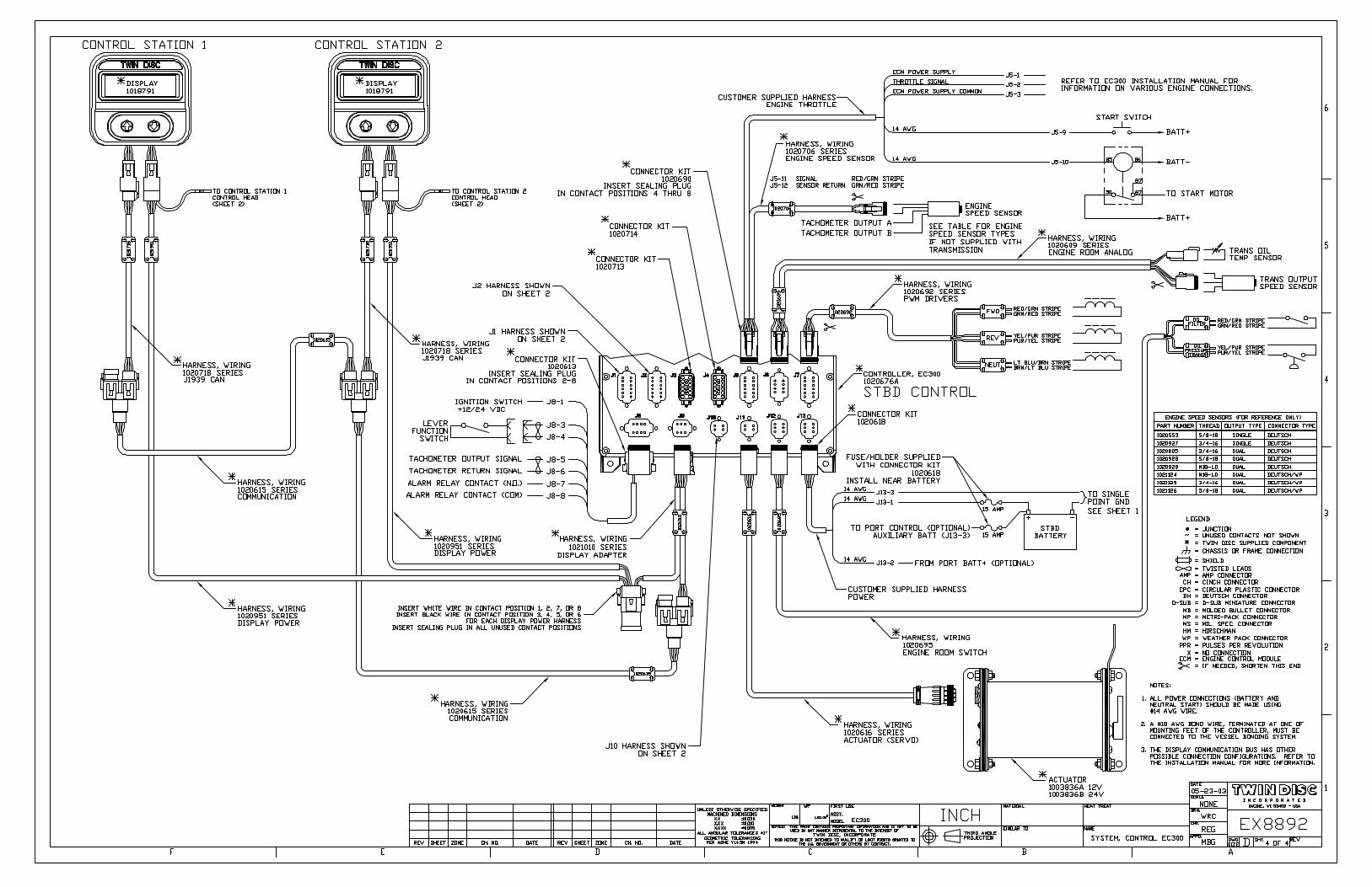

206
Twin Disc, IncorporatedEngineering Drawings
EC300 Marine Control System Installation Manual #1020607
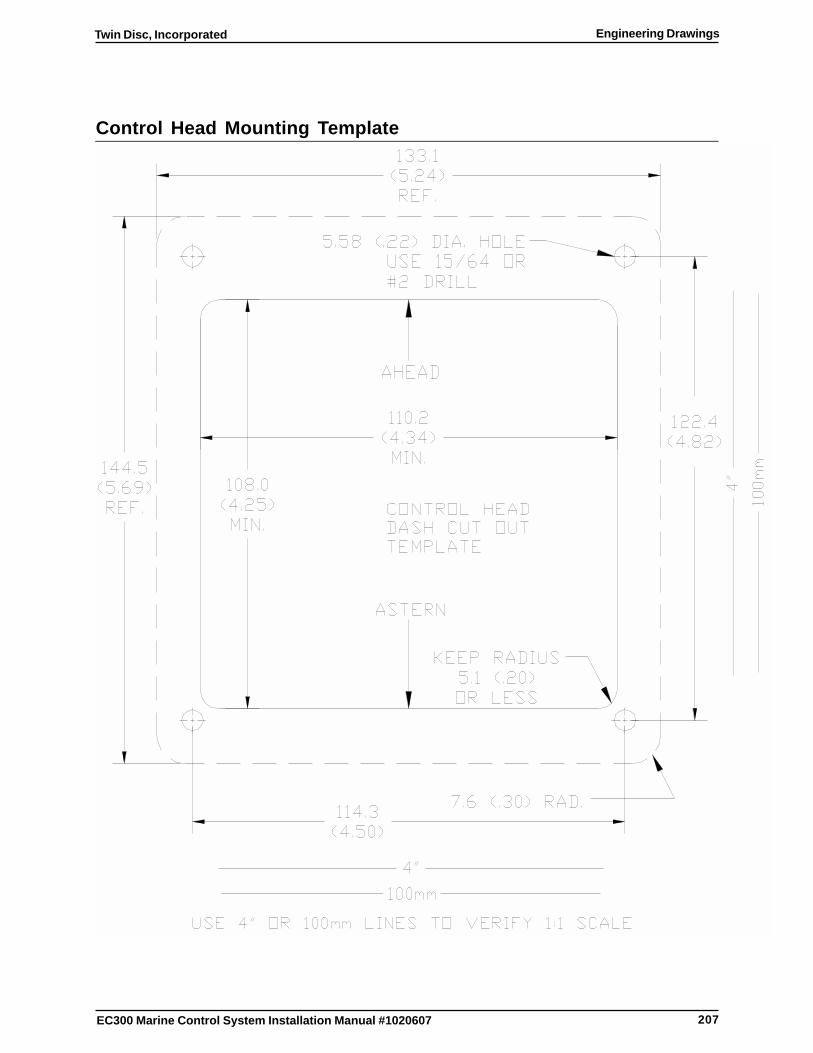
207
Twin Disc, Incorporated Engineering Drawings
EC300 Marine Control System Installation Manual #1020607
Control Head Mounting Template

208
Twin Disc, IncorporatedEngineering Drawings
EC300 Marine Control System Installation Manual #1020607
This page intentionally blank
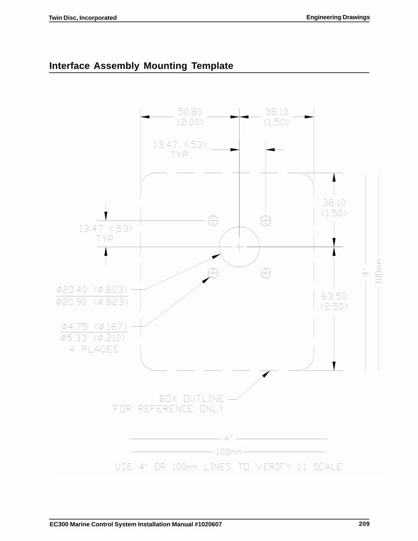
209
Twin Disc, Incorporated Engineering Drawings
EC300 Marine Control System Installation Manual #1020607
Interface Assembly Mounting Template

210
Twin Disc, IncorporatedEngineering Drawings
EC300 Marine Control System Installation Manual #1020607
This page intentionally blank
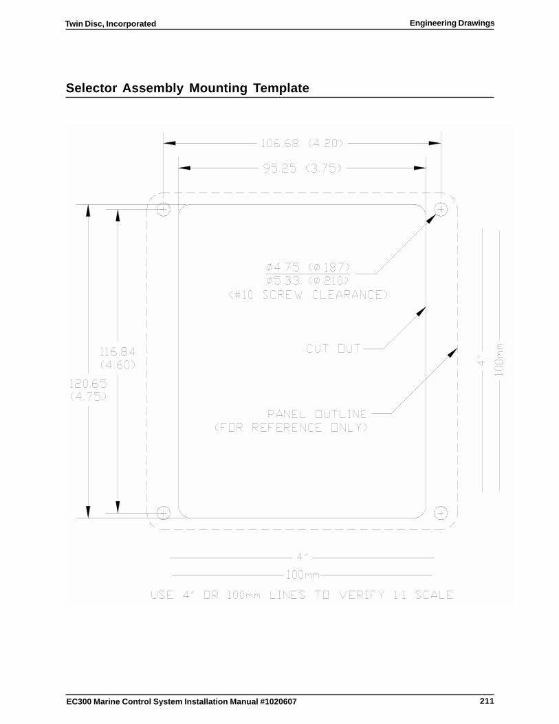
211
Twin Disc, Incorporated Engineering Drawings
EC300 Marine Control System Installation Manual #1020607
Selector Assembly Mounting Template

212
Twin Disc, IncorporatedEngineering Drawings
EC300 Marine Control System Installation Manual #1020607
This page intentionally blank

A-1
Twin Disc, Incorporated Appendix
EC300 Marine Control System Installation Manual #1020607
Appendix
Caterpillar Engine Connection RequirementsThis throttle signal configuration is known as a PWM/Duty Cycle. The EC300throttle signal is set to approximately 9% at idle and 92% at full throttle. Generally,the EC300 is connected to the engine control at the connections designatedfor the “Primary Throttle Position Sensor” or “TPS”. Depending on the modeland harnessing provided, the EC300 Engine Harness (J5) will either beconnected to the “Primary Throttle Position Sensor” connector, or directly tothe Customer Connector. See Table 7 and Table 8. Refer to the enginemanufacturer’s literature to resolve any discrepancies.
Table 7. Engine Connections at Caterpillar’s TPS Connector
enignE003CE5JssenraH
langiS003CEnoitpircseD
SPTrotcennoC
noitpircseDlangiSenignE
1-5J ylppuSrewoPMCE A )1etoN( MCE(evitisoPdehctiwS)rewoP
2-5J langiSelttorhT C noitisoPelttorhTyramirPlangiS
3-5J ylppuSrewoPMCEnommoC
B )2etoN( )rewoPMCE(yrettaBevitageN
.gniriwMCEmorfdnadehctiwsebdluohs1-5JotnoitcennocevitisoPyrettaBehT)1.subyrettabton-gniriwMCEmorfebdluohs3-5JotnoitcennocevitageNyrettaBehT)2
Table 8. Engine Connections at Caterpillar’s Customer Connector
enignE003CE5JssenraH
langiS003CEnoitpircseD
rotcennoCremotsuC langiSenignEnoitpircseD
1-5J ylppuSrewoPMCE 03niP +yrettaB)dehctiws(
2-5J langiSelttorhT 01niP elttorhTyramirP
3-5J ylppuSrewoPMCEnommoC
2niP -yrettaB
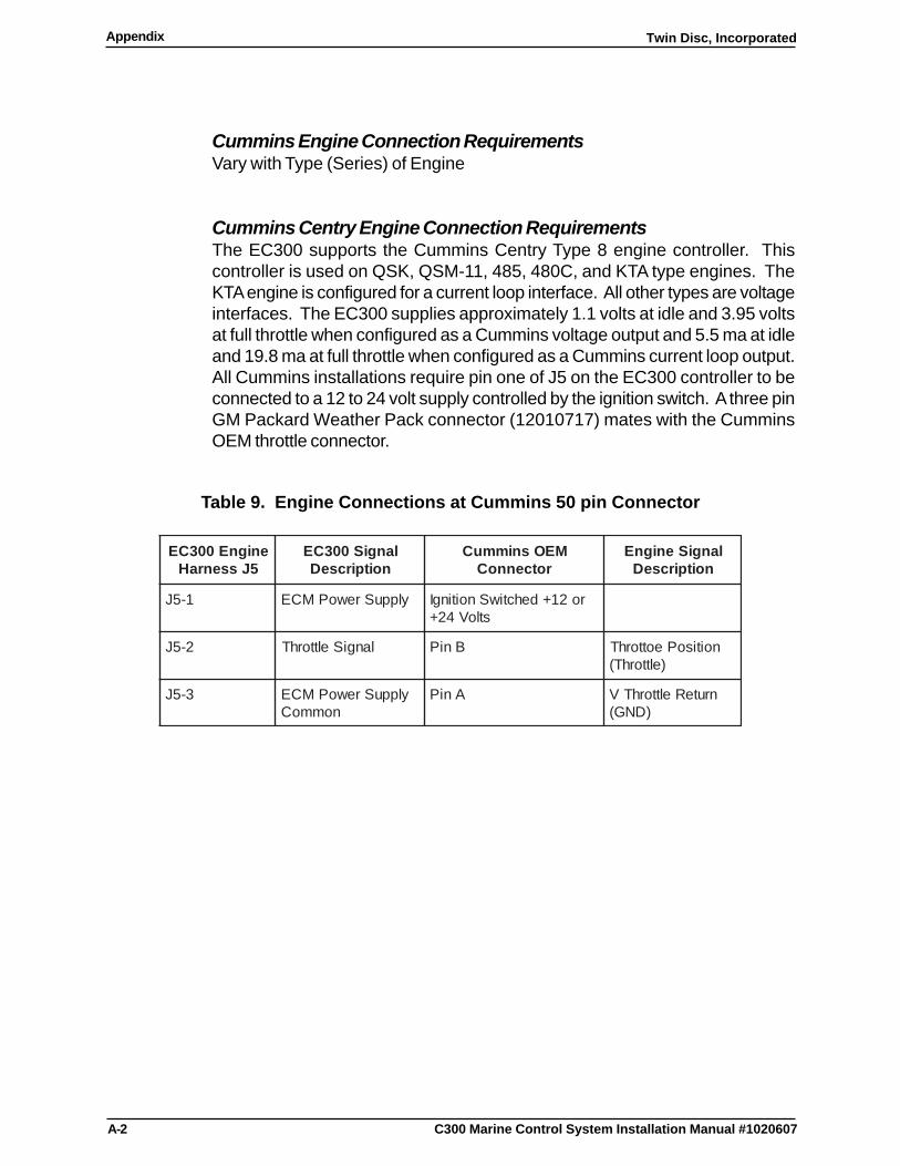
A-2
Twin Disc, IncorporatedAppendix
C300 Marine Control System Installation Manual #1020607
Cummins Engine Connection RequirementsVary with Type (Series) of Engine
Cummins Centry Engine Connection RequirementsThe EC300 supports the Cummins Centry Type 8 engine controller. Thiscontroller is used on QSK, QSM-11, 485, 480C, and KTA type engines. TheKTA engine is configured for a current loop interface. All other types are voltageinterfaces. The EC300 supplies approximately 1.1 volts at idle and 3.95 voltsat full throttle when configured as a Cummins voltage output and 5.5 ma at idleand 19.8 ma at full throttle when configured as a Cummins current loop output.All Cummins installations require pin one of J5 on the EC300 controller to beconnected to a 12 to 24 volt supply controlled by the ignition switch. A three pinGM Packard Weather Pack connector (12010717) mates with the CumminsOEM throttle connector.
Table 9. Engine Connections at Cummins 50 pin Connector
enignE003CE5JssenraH
langiS003CEnoitpircseD
MEOsnimmuCrotcennoC
langiSenignEnoitpircseD
1-5J ylppuSrewoPMCE ro21+dehctiwSnoitingIstloV42+
2-5J langiSelttorhT BniP noitisoPeottorhT)elttorhT(
3-5J ylppuSrewoPMCEnommoC
AniP nruteRelttorhTV)DNG(

A-3
Twin Disc, Incorporated Appendix
EC300 Marine Control System Installation Manual #1020607
Cummins Quantum Voltage Type Engine Connection RequirementsThis throttle signal configuration is a DC voltage. The EC300 throttle signal isset to approximately 0.1.1 VDC at idle and 3.95 VDC at full throttle. Thisconfiguration is typically used with Cummins QSM-11, 485C and QSK modelswith Quantum series engine controls. Generally, the EC300 is connected to theengine control at the connections designated for the throttle or throttle pot.Depending on the model and harnessing, the EC300 wiring will connect to the“Throttle” or the “OEM” connector. See Table10 and Table 11. Refer to theengine manufacturer’s literature to resolve any discrepancies.
Table 10. Engine Connections at the Cummins Throttle Harness Stub
enignE003CE5JssenraH
langiS003CEnoitpircseD
elttorhTrotcennoC
noitpircseDlangiSenignE
1-5J ylppuSrewoPMCE noitingI21+dehctiwS
stloV42+ro
2-5J langiSelttorhT BniPDD )elttorhT(noitisoPelttorhT
3-5J ylppuSrewoPMCEnommoC
AniPDD )DNG(nruteRelttorhTV
."DD"erasrotcennoCtoPelttorhTKSQllatoN:etoN
Table 11. Engine Connections at the Cummins Quantum QSM-11 Enginewith Voltage Control
enignE003CE5JssenraH
langiS003CEnoitpircseD
rotcennoCMEO11-MSQ
langiSenignEnoitpircseD
1-5J ylppuSrewoPMCE CniPDD )PTV(elttorhTV
2-5J langiSelttorhT BniPDD noitisoPelttorhT)elttorhT(
3-5J ylppuSrewoPMCEnommoC
AniPDD nruteRelttorhTV)DNG(
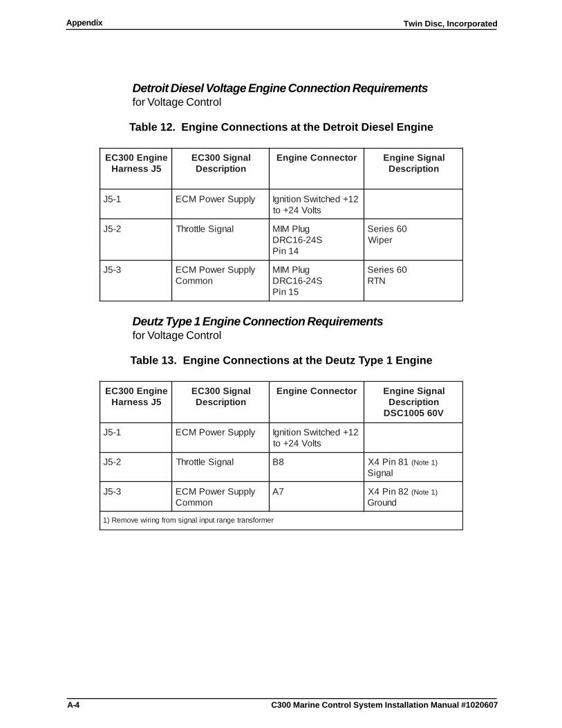
A-4
Twin Disc, IncorporatedAppendix
C300 Marine Control System Installation Manual #1020607
Detroit Diesel Voltage Engine Connection Requirementsfor Voltage Control
Table 12. Engine Connections at the Detroit Diesel Engine
enignE003CE5JssenraH
langiS003CEnoitpircseD
rotcennoCenignE langiSenignEnoitpircseD
1-5J ylppuSrewoPMCE 21+dehctiwSnoitingIstloV42+ot
2-5J langiSelttorhT gulPMIMS42-61CRD
41niP
06seireSrepiW
3-5J ylppuSrewoPMCEnommoC
gulPMIMS42-61CRD
51niP
06seireSNTR
Deutz Type 1 Engine Connection Requirementsfor Voltage Control
Table 13. Engine Connections at the Deutz Type 1 Engine
enignE003CE5JssenraH
langiS003CEnoitpircseD
rotcennoCenignE langiSenignEnoitpircseDV065001CSD
1-5J ylppuSrewoPMCE 21+dehctiwSnoitingIstloV42+ot
2-5J langiSelttorhT 8B 18niP4X )1etoN(langiS
3-5J ylppuSrewoPMCEnommoC
7A 28niP4X )1etoN(dnuorG
remrofsnartegnartupnilangismorfgniriwevomeR)1
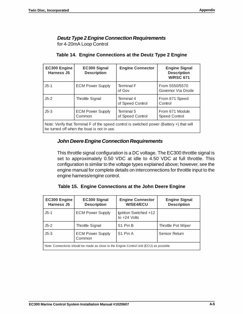
A-5
Twin Disc, Incorporated Appendix
EC300 Marine Control System Installation Manual #1020607
Deutz Type 2 Engine Connection Requirementsfor 4-20mA Loop Control
Table 14. Engine Connections at the Deutz Type 2 Engine
enignE003CE5JssenraH
langiS003CEnoitpircseD
rotcennoCenignE langiSenignEnoitpircseD176CSR/W
1-5J ylppuSrewoPMCE FlanimreTvoGfo
0755/0555morFedoiDaiVronrevoG
2-5J langiSelttorhT 4lanimreTlortnoCdeepSfo
deepS176morFlortnoC
3-5J ylppuSrewoPMCEnommoC
5lanimreTlortnoCdeepSfo
eludoM176morFlortnoCdeepS
lliwtaht)+yrettaB(rewopdehctiwssilortnocdeepsehtfoFlanimreTtahtyfireV:etoN.esunitonsitaobehtnehwffodenruteb
John Deere Engine Connection Requirements
This throttle signal configuration is a DC voltage. The EC300 throttle signal isset to approximately 0.50 VDC at idle to 4.50 VDC at full throttle. Thisconfiguration is similar to the voltage types explained above; however, see theengine manual for complete details on interconnections for throttle input to theengine harness/engine control.
Table 15. Engine Connections at the John Deere Engine
enignE003CE5JssenraH
langiS003CEnoitpircseD
rotcennoCenignEUCE/4ES/W
langiSenignEnoitpircseD
1-5J ylppuSrewoPMCE 21+dehctiwSnoitingIstloV42+ot
2-5J langiSelttorhT BniP1S repiWtoPelttorhT
3-5J ylppuSrewoPMCEnommoC
AniP1S nruteRrosneS
elbissopsa)UCE(tinUlortnoCenignEehtotesolcsaedamebdluohssnoitcennoC:etoN
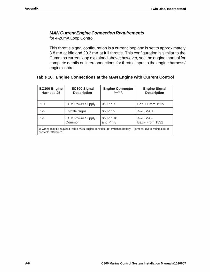
A-6
Twin Disc, IncorporatedAppendix
C300 Marine Control System Installation Manual #1020607
MAN Current Engine Connection Requirementsfor 4-20mA Loop Control
This throttle signal configuration is a current loop and is set to approximately3.8 mA at idle and 20.3 mA at full throttle. This configuration is similar to theCummins current loop explained above; however, see the engine manual forcomplete details on interconnections for throttle input to the engine harness/engine control.
Table 16. Engine Connections at the MAN Engine with Current Control
enignE003CE5JssenraH
langiS003CEnoitpircseD
rotcennoCenignE)1etoN(
langiSenignEnoitpircseD
1-5J ylppuSrewoPMCE 7niP9X 515TmorF+ttaB
2-5J langiSelttorhT 9niP9X +AM02-4
3-5J ylppuSrewoPMCEnommoC
01niP9X8niPdna
-AM02-4135TmorF-ttaB
foedisgniriwot)51lanimret(+yrettabdehctiwstegotlortnocenigneNAMedisnideriuqerebyamgniriW)1.7niP9Xrotcennoc
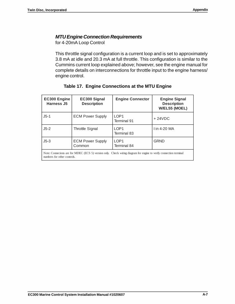
A-7
Twin Disc, Incorporated Appendix
EC300 Marine Control System Installation Manual #1020607
MTU Engine Connection Requirementsfor 4-20mA Loop Control
This throttle signal configuration is a current loop and is set to approximately3.8 mA at idle and 20.3 mA at full throttle. This configuration is similar to theCummins current loop explained above; however, see the engine manual forcomplete details on interconnections for throttle input to the engine harness/engine control.
Table 17. Engine Connections at the MTU Engine
enignE003CE5JssenraH
langiS003CEnoitpircseD
rotcennoCenignE langiSenignEnoitpircseD
)LEOM(55LE/W
1-5J ylppuSrewoPMCE 1POL19lanimreT CDV42+
2-5J langiSelttorhT 1POL38lanimreT
AM02-4niI
3-5J ylppuSrewoPMCEnommoC
1POL48lanimreT
DNRG
lanimretnoitcennocyfirevotenignerofmargaidgniriwkcehC.ylnonoisrev)5SCE(CEDMroferasnoicennoC:etoN.slortnocrehtorofsrebmun
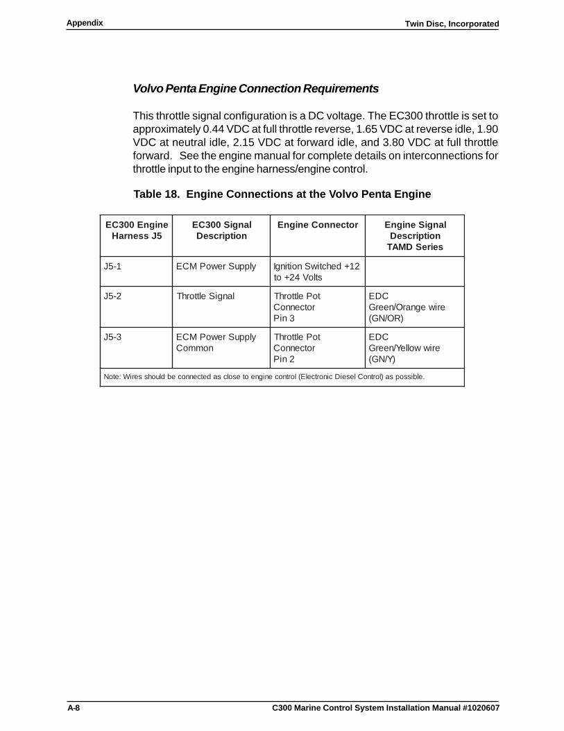
A-8
Twin Disc, IncorporatedAppendix
C300 Marine Control System Installation Manual #1020607
Volvo Penta Engine Connection Requirements
This throttle signal configuration is a DC voltage. The EC300 throttle is set toapproximately 0.44 VDC at full throttle reverse, 1.65 VDC at reverse idle, 1.90VDC at neutral idle, 2.15 VDC at forward idle, and 3.80 VDC at full throttleforward. See the engine manual for complete details on interconnections forthrottle input to the engine harness/engine control.
Table 18. Engine Connections at the Volvo Penta Engine
enignE003CE5JssenraH
langiS003CEnoitpircseD
rotcennoCenignE langiSenignEnoitpircseDseireSDMAT
1-5J ylppuSrewoPMCE 21+dehctiwSnoitingIstloV42+ot
2-5J langiSelttorhT toPelttorhTrotcennoC
3niP
CDEeriwegnarO/neerG
)RO/NG(
3-5J ylppuSrewoPMCEnommoC
toPelttorhTrotcennoC
2niP
CDEeriwwolleY/neerG
)Y/NG(
.elbissopsa)lortnoCleseiDcinortcelE(lortnocenigneotesolcsadetcennocebdluohsseriW:etoN
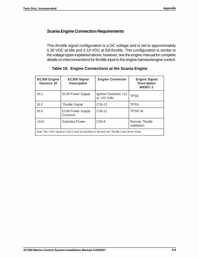
A-9
Twin Disc, Incorporated Appendix
EC300 Marine Control System Installation Manual #1020607
Scania Engine Connection Requirements
This throttle signal configuration is a DC voltage and is set to approximately0.35 VDC at idle and 3.10 VDC at full throttle. This configuration is similar tothe voltage types explained above; however, see the engine manual for completedetails on interconnections for throttle input to the engine harness/engine control.
Table 19. Engine Connections at the Scania Engine
enignE003CE5JssenraH
langiS003CEnoitpircseD
rotcennoCenignE langiSenignEnoitpircseD
2CED/W
1-5J ylppuSrewoPMCE 21+dehctiwSnoitingIstloV42+ot ESPT
2-5J langiSelttorhT 21-63C SSPT
3-5J ylppuSrewoPMCEnommoC
11-63C eYRSPT
V42+ rewoPdehctiwS 9-63C elttorhTetomeRnoitadilaV
.edomemoHpmiLelttorhT'tes'tneverpotdedivorpybtsum9-63CotlangisV42+ehT:etoN
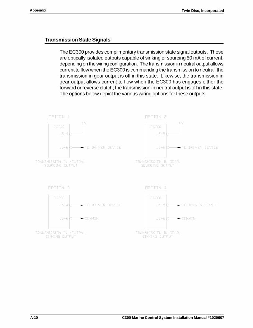
A-10
Twin Disc, IncorporatedAppendix
C300 Marine Control System Installation Manual #1020607
Transmission State Signals
The EC300 provides complimentary transmission state signal outputs. Theseare optically isolated outputs capable of sinking or sourcing 50 mA of current,depending on the wiring configuration. The transmission in neutral output allowscurrent to flow when the EC300 is commanding the transmission to neutral; thetransmission in gear output is off in this state. Likewise, the transmission ingear output allows current to flow when the EC300 has engages either theforward or reverse clutch; the transmission in neutral output is off in this state.The options below depict the various wiring options for these outputs.

a

#1020607 09/03
TWIN DISC, INCORPORATED RACINE, WISCONSIN 53403, U.S.A. 262-638-4000/262-638-4482 (FAX) WWW.TWINDISC.COM