Embed Size (px)
Citation preview
EC20 Elevator Door Controller

EC20 elevator door controller Content
1
Content
1 Safety precautions ...................................................................................................................................... 3
1.1 Safety definition ................................................................................................................................... 3
1.2 Warning symbols ................................................................................................................................. 3
1.3 Safety guidelines ................................................................................................................................. 3
2 Product overview ......................................................................................................................................... 6
2.1 Quick start-up ...................................................................................................................................... 6
2.2 Product specification ........................................................................................................................... 7
2.3 Name plate........................................................................................................................................... 9
2.4 Type designation key .......................................................................................................................... 9
2.5 Rated specifications ............................................................................................................................ 9
2.6 Structure diagram ................................................................................................................................ 9
3 Installation guidelines............................................................................................................................... 11
3.1 Mechanical installation ...................................................................................................................... 11
3.2 Standard wiring .................................................................................................................................. 13
3.3 Layout protection ............................................................................................................................... 15
4 Keypad operation procedure ................................................................................................................... 17
4.1 Keypad introduction .......................................................................................................................... 17
4.2 Keypad displaying ............................................................................................................................. 19
4.3 Keypad operation .............................................................................................................................. 20
5 Function parameters ................................................................................................................................. 23
6 Commissioning instruction ..................................................................................................................... 48
6.1 Running commissioning.................................................................................................................... 48
6.2 Speed control mode .......................................................................................................................... 48
6.3 Distance control mode 1 ................................................................................................................... 51
6.4 Distance control mode 2 ................................................................................................................... 53
6.5 CLOSE obstruction ........................................................................................................................... 56
7 Fault ............................................................................................................................................................. 58
7.1 Fault prevention................................................................................................................................. 58
7.2 Troubleshooting ................................................................................................................................. 62
Appendix A Technical data.......................................................................................................................... 67
A.1 Ratings ............................................................................................................................................... 67

EC20 elevator door controller Content
2
A.2 CE ...................................................................................................................................................... 68
A.3 EMC regulations ............................................................................................................................... 68
Appendix B Dimension drawings .............................................................................................................. 70
B.1 External keypad (optional) structure ............................................................................................... 70
B.2 Controller chart.................................................................................................................................. 71
Appendix C Peripheral options and parts ................................................................................................ 72
C.1 Peripheral wiring ............................................................................................................................... 72
C.2 Power supply .................................................................................................................................... 73
C.3 Cables................................................................................................................................................ 73
C.4 Breaker and electromagnetic contactor .......................................................................................... 74
C.6 Filters ................................................................................................................................................. 74
C.7 Braking components......................................................................................................................... 75
Appendix D Further information ................................................................................................................ 77
D.1 Product and service inquiries .......................................................................................................... 77
D.2 Feedback of INVT controllers manuals........................................................................................... 77
D.3 Document library on the internet ..................................................................................................... 77
EC20 elevator door controller Safety precautions
3
1 Safety precautions
Please read this manual carefully and follow all safety precautions before moving, installing, operating
and servicing the controller. If ignored, physical injury or death may occur, or damage may occur to the
devices.
If any physical injury or death or damage to the devices occurs for ignoring to the safety precautions in
the manual, our company will not be responsible for any damages and we are not legally bound in any
manner.
1.1 Safety definition
Danger: Serious physical injury or even death may occur if not follow relevant
requirements
Warning: Physical injury or damage to the devices may occur if not follow relevant
requirements
Note: Physical hurt may occur if not follow relevant requirements
Qualified
electricians:
People working on the device should take part in professional electrical and
safety training, receive the certification and be familiar with all steps and
requirements of installing, commissioning, operating and maintaining the
device to avoid any emergency.
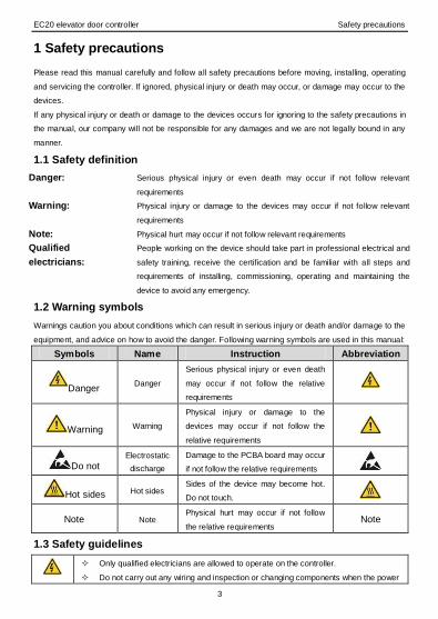
1.2 Warning symbols
Warnings caution you about conditions which can result in serious injury or death and/or damage to the
equipment, and advice on how to avoid the danger. Following warning symbols are used in this manual:
Symbols Name Instruction Abbreviation
Danger Danger
Serious physical injury or even death
may occur if not follow the relative
requirements
Warning Warning
Physical injury or damage to the
devices may occur if not follow the
relative requirements
Do not Electrostatic
discharge
Damage to the PCBA board may occur
if not follow the relative requirements
Hot sides Hot sides Sides of the device may become hot.
Do not touch.
Note Note Physical hurt may occur if not follow
the relative requirements Note
1.3 Safety guidelines
Only qualified electricians are allowed to operate on the controller.
Do not carry out any wiring and inspection or changing components when the power

EC20 elevator door controller Safety precautions
4
supply is applied. Ensure all input power supply is disconnected before wiring and
checking and always wait for at least the time designated on the controller or until
the DC bus voltage is less than 36V. Below is the table of the wait time:
Controller module Minimum wait time
1PH 220V 0.4kW-2.2kW 5 minutes
Do not refit the controller unauthorized; otherwise fire, electric shock or other injury
may occur.
The base of the radiator may become hot during running. Do not touch to avoid hurt.
The electrical parts and components inside the controller are electrostatic. Take
measurements to avoid electrostatic discharge during relevant operation.
1.3.1 Delivery and installation
Please install the controller on fire-retardant material and keep the controller away
from combustible materials.
Connect the braking optional parts (braking resistors, braking units or feedback
units) according to the wiring diagram.
Do not operate on the controller if there is any damage or components loss to the
controller.
Do not touch the controller with wet items or body, otherwise electric shock may
occur.
Note:
Select appropriate moving and installing tools to ensure a safe and normal running of the controller
and avoid physical injury or death. For physical safety, the erector should take some mechanical
protective measurements, such as wearing exposure shoes and working uniforms.
Ensure to avoid physical shock or vibration during delivery and installation.
Do not carry the controller by its cover. The cover may fall off.
Install away from children and other public places.
The controller cannot meet the requirements of low voltage protection in IEC61800-5-1 if the sea
level of installation site is above 2000m.
The leakage current of the controller may be above 3.5mA during operation. Ground with proper
techniques and ensure the grounding resistor is less than 10Ω. The conductivity of PE grounding
conductor is the same as that of the phase conductor (with the same cross sectional area).
L and N are the input terminals of the power supply, while U, V and W are the motor terminals.
Please connect the input power cables and motor cables with proper techniques; otherwise the
damage to the controller may occur.
1.3.2 Commissioning and running
Disconnect all power supplies applied to the controller before the terminal wiring
and wait for at least the designated time after disconnecting the power supply.
EC20 elevator door controller Safety precautions
5
High voltage is present inside the controller during running. Do not carry out any
operation except for the keypad setting.
The controller can not be used as “Emergency-stop device”.
The controller can not be used to break the motor suddenly. A mechanical braking
device should be provided.
Note:
Do not switch on or off the input power supply of the controller frequently.
For controllers that have been stored for a long time, check and fix the capacitance and try to run it
again before utilization (see Maintenance and Hardware Fault Diagnose).
Cover the front board before running, otherwise electric shock may occur.
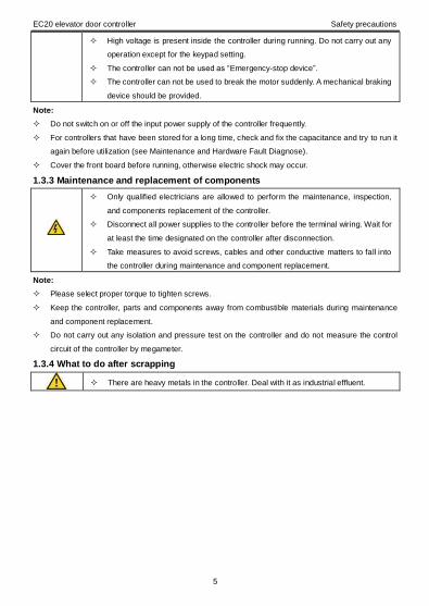
1.3.3 Maintenance and replacement of components
Only qualified electricians are allowed to perform the maintenance, inspection,
and components replacement of the controller.
Disconnect all power supplies to the controller before the terminal wiring. Wait for
at least the time designated on the controller after disconnection.
Take measures to avoid screws, cables and other conductive matters to fall into
the controller during maintenance and component replacement.
Note:
Please select proper torque to tighten screws.
Keep the controller, parts and components away from combustible materials during maintenance
and component replacement.
Do not carry out any isolation and pressure test on the controller and do not measure the control
circuit of the controller by megameter.
1.3.4 What to do after scrapping
There are heavy metals in the controller. Deal with it as industrial effluent.

EC20 elevator door controller Product overview
6
2 Product overview
2.1 Quick start-up
2.1.1 Unpacking inspection
Check as follows after receiving products:
1. Check that there are no damage and humidification to the package. If not, please contact with local
agents or INVT offices.
2. Check the information on the type designation label on the outside of the package to verify that the
drive is of the correct type. If not, please contact with local dealers or INVT offices.
3. Check that there are no signs of water in the package and no signs of damage or breach to the
controller. If not, please contact with local dealers or INVT offices.
4. Check the information on the type designation label on the outside of the package to verify that the
name plate is of the correct type. If not, please contact with local dealers or INVT offices.
5. Check to ensure the accessories (including user’s manual and control keypad) inside the device is
complete. If not, please contact with local dealers or INVT offices.
2.1.2 Application confirmation
Check the machine before beginning to use the controller:
1. Check the load type to verify that there is no overload of the controller during work and check that
whether the drive needs to modify the power degree.
2. Check that the actual current of the motor is less than the rated current of the controller.
3. Check that the control accuracy of the load is the same of the controller.
4. Check that the incoming supply voltage is correspondent to the rated voltage of the controller.
2.1.3 Environment
Check as follows before the actual installation and usage:
1. Check that the ambient temperature of the controller is below 40°C. If exceeds, derate1% for every
additional 1°C. Additionally, the controller can not be used if the ambient temperature is above 50°C.
Note: For the cabinet controller, the ambient temperature means the air temperature inside the
cabinet.
2. Check that the ambient temperature of the controller in actual usage is above -10°C. If not, add
heating facilities.
Note: For the cabinet controller, the ambient temperature means the air temperature inside the
cabinet.
3. Check that the altitude of the actual usage site is below 1000m. If exceeds, derate1% for every
additional 100m.
4. Check that the humidity of the actual usage site is below 90% and condensation is not allowed. If
not, add additional protection controllers.
5. Check that the actual usage site is away from direct sunlight and foreign objects can not enter the

EC20 elevator door controller Product overview
7
controller. If not, add additional protective measures.
6. Check that there is no conductive dust or flammable gas in the actual usage site. If not, add
additional protection to controllers.
2.1.4 Installation confirmation
Check as follows after the installation:
1. Check that the load range of the input and output cables meet the need of actual load.
2. Check that the accessories of the controller are correctly and properly installed. The installation
cables should meet the needs of every component (including reactors, input filters, output reactors,
output filters, DC reactors, braking units and braking resistors).
3. Check that the controller is installed on non-flammable materials and the calorific accessories
(reactors and brake resistors) are away from flammable materials.
4. Check that all control cables and power cables are run separately and the routation complies with
EMC requirement.
5. Check that all grounding systems are properly grounded according to the requirements of the
controller.
6. Check that the free space during installation is sufficient according to the instructions in user’s
manual.
7. Check that the installation conforms to the instructions in user’s manual. The drive must be
installed in an upright position.
8. Check that the external connection terminals are tightly fastened and the torque is appropriate.
9. Check that there are no screws, cables and other conductive items left in the controller. If not, get
them out.
2.1.5 Basic commissioning
Complete the basic commissioning as follows before actual utilization:
1. Autotune. If possible, de-coupled from the motor load to start dynamic autotune. Or if not, static
autotune is available.
2. Adjust the ACC/DEC time according to the actual running of the load.
3. Commission the device via jogging and check that the rotation direction is as required. If not,
change the rotation direction by changing the wiring of motor.
4. Set all control parameters and then operate.
2.2 Product specification
Function Specification
Power input
Input voltage (V) AC 1PH 220V (-15%)~240V(+10%)
Input current (A) Refer to the rated value
Input frequency (Hz) 50Hz or 60Hz Allowed range: 47~63Hz
Power Output motor capacity Refer to the rated value

EC20 elevator door controller Product overview
8
Function Specification
output (kW)
Rated output (kVA) Refer to the rated value
Output current (A) Refer to the rated value
Output voltage (V) 0~input voltage
Technical
control
feature
Control mode SVPWM, SVC
Adjustable-speed ratio 1:100
Speed control accuracy ±0.2% (SVC)
Speed fluctuation ± 0.3% ( SVC)
Torque response <20ms (SVC)
Torque control accuracy 10%
Starting torque 0. 5Hz/150% ( SVC)
Overload capability
150% of rated current: 1 minute
180% of rated current: 10 seconds
200% of rated current: 1 second
Peripheral
interface
Digital input 7 common inputs, the Max. frequency: 1kHz
Digital output 1 Y1 terminal output; 2 programmable relay outputs
CAN communication Protocol: extension frame, communication baud rate
40K
Encoder port 12V encoder, support OC input, the Max. frequency:
10kHz
Relay output
2 programmable relay outputs
RO1A NO, RO1B NC, RO1C common terminal
RO2A NO, RO2B NC, RO2C common terminal
Contact capacity: 3A/AC250V
Others
Mountable method Wall and rail mountable
Braking unit Embedded
EMI filter Optional filter: meet the degree requirement of
IEC61800-3 C2, IEC61800-3 C3
Temperature of the
running environment -10~50°C, derate above 40°C
Altitude
<1000m
If the sea level is above 1000m, please derate 1% for
every additional 100m.
Protective degree
IP20
Note: The controller with plastic casing should be
installed in metal distribution cabinet, which conforms
to IP20 and of which the top conforms to IP3X.
Safety Meet the requirement of CE
Cooling Air-cooling

EC20 elevator door controller Product overview
9
2.3 Name plate
Figure 2-1 Name plate
Note: This is the example of the name plate for the standard products, and CE/TUV/IP20 will be marked
according to the actual situations.
2.4 Type designation key
The type designation contains information on the controller. The user can find the type designation on
the type designation label attached to the controller or the simple name plate.
EC20 – 0R4G – S2 ① ② ③
Figure 2-2 Product type
Key No. Detailed
description Detailed content
Product
abbreviation ① Product abbreviation EC20
Rated power ② Power range+ Load
type
0R4-0.4kW
G: Constant torque load
Voltage degree ③ Voltage degree S2: AC 1PH 220V(-15%)~240V(+10%)
2.5 Rated specifications
Model Rated
output power(kW)
Rated input
current(A)
Rated output
current(A)
EC20-0R4G-S2 0.4 6.5 2.5
EC20-0R7G-S2 0.75 9.3 4.2
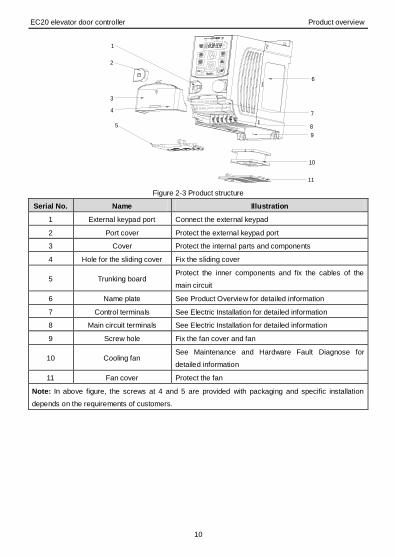
2.6 Structure diagram
Below is the layout figure of the controller.
EC20 elevator door controller Product overview
10
6
11
7
9
3
2
5
1
8
10
4
Figure 2-3 Product structure
Serial No. Name Illustration
1 External keypad port Connect the external keypad
2 Port cover Protect the external keypad port
3 Cover Protect the internal parts and components
4 Hole for the sliding cover Fix the sliding cover
5 Trunking board Protect the inner components and fix the cables of the
main circuit
6 Name plate See Product Overview for detailed information
7 Control terminals See Electric Installation for detailed information
8 Main circuit terminals See Electric Installation for detailed information
9 Screw hole Fix the fan cover and fan
10 Cooling fan See Maintenance and Hardware Fault Diagnose for
detailed information
11 Fan cover Protect the fan
Note: In above figure, the screws at 4 and 5 are provided with packaging and specific installation
depends on the requirements of customers.

EC20 elevator door controller Installation guidelines
11
3 Installation guidelines
The chapter describes the mechanical installation and electric installation.
Only qualified electricians are allowed to carry out what described in this chapter.
Please operate as the instructions in Safety Precautions. Ignoring these may cause
physical injury or death or damage to the devices.
Ensure the power supply of the controller is disconnected during the operation. Wait
for at least the time designated after the disconnection if the power supply is applied.
The installation and design of the controller should be complied with the requirement
of the local laws and regulations in the installation site. If the installation infringes the
requirement, our company will exempt from any responsibility. Additionally, if users
do not comply with the suggestion, some damage beyond the assured maintenance
range may occur.
3.1 Mechanical installation
3.1.1 Installation environment
The installation environment is the safeguard for a full performance and long-term stable functions of the
controller. Check the installation environment as follows:
Environment Conditions
Installation site Indoor
Environment
temperature
-10°C~+50°C, and the temperature changing rate is less than
0.5°C/minute.
If the ambient temperature of the controller is above 40°C, derate 1% for
every additional 1°C.
It is not recommended to use the controller if the ambient temperature is
above 50°C.
In order to improve the reliability of the device, do not use the controller
if the ambient temperature changes frequently.
Please provide cooling fan or air conditioner to control the internal
ambient temperature below the required one if the controller is used in a
close space such as in the control cabinet.
When the temperature is too low, if the controller needs to restart to run
after a long stop, it is necessary to provide an external heating device to
increase the internal temperature, otherwise damage to the devices
may occur.
Humidity RH≤90%
No condensation is allowed.
Storage
temperature
-40°C~+70°C, and the temperature changing rate is less than
1°C/minute.
Running environment The installation site of the controller should:

EC20 elevator door controller Installation guidelines
12
Environment Conditions
condition keep away from the electromagnetic radiation source;
keep away from contaminative air, such as corrosive gas, oil mist and
flammable gas;
ensure foreign objects, such as metal power, dust, oil, water can not
enter into the controller(do not install the controller on the flammable
materials such as wood);
keep away from direct sunlight, oil mist, steam and vibration
environment.
Altitude
Below 1000m
If the sea level is above 1000m, please derate 1% for every additional
100m.
Vibration ≤ 5.8m/s2(0.6g)
Installation direction The controller should be installed on an upright position to ensure
sufficient cooling effect.
Note:
EC20 series controllers should be installed in a clean and ventilated environment according
to enclosure classification.
Cooling air must be clean, free from corrosive materials and electrically conductive dust.
3.1.2 Installation direction
The controller may be installed on the wall or in a cabinet.
The controller needs be installed in the vertical position. Check the installation site according to the
requirements below. Refer to chapter Dimension Drawings in the appendix for frame details.
3.1.3 Installation manner
The controller can be installed in two different ways, depending on the frame size:
Figure 3-1 Wall mounting Figure 3-2 Rail mounting
Note: The minimum space of A and B is 100mm. H is 36.6mm and W is 35.0mm.
EC20 elevator door controller Installation guidelines
13
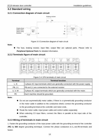
3.2 Standard wiring
3.2.1 Connection diagram of main circuit
L
N
W
V
U
PE
M
(+) PB
Single-phase
220V(-15%)~
240V(+10%)
50/60Hz
Braking resistor
Input
filter
Fuse
Output
filter
Figure 3-3 Connection diagram of main circuit
Note:
The fuse, braking resistor, input filter, output filter are optional parts. Please refer to
Peripheral Optional Parts for detailed information.
3.2.2 Terminals figure of main circuit
Figure 3-4 1PH terminals of main circuit
Terminal Terminal function
L, N 1-phase AC input terminals which are generally connected with the power supply.
PB, (+) PB and (+) are connected to the external resistor.
U, V, W 3-phase AC output terminals which are generally connected with the motor.
PE Each machine should be grounded.
Note:
Do not use asymmetrically motor cables. If there is a symmetrically grounding conductor
in the motor cable in addition to the conductive shield, connect the grounding conductor
to the grounding terminal at the controller and motor ends.
Route the motor cable, input power cable and control cables separately.
When selecting C3 input filters, connect the filters in parallel at the input side of the
controller.
3.2.3 Wiring of terminals in main circuit
1. Fasten the grounding conductor of the input power cable with the grounding terminal of the controller
(PE) by 360 degree grounding technique. Connect the phase conductors to L and N terminals and
fasten.

EC20 elevator door controller Installation guidelines
14
2. Strip the motor cable and connect the shield to the grounding terminal of the controller by 360 degree
grounding technique. Connect the phase conductors to U, V and W terminals and fasten.
3. Connect the optional brake resistor with a shielded cable to the designated position by the same
procedures in the previous step.
4. Secure the cables outside the controller mechanically.
3.2.4 Wiring diagram of control circuit
PW
+12VCOM
S1
S2
S3
S4
S5
S6
S7
OPEN signal input
CLOSE signal input
OPEN arrival input
CLOSE arrival input
OPEN DEC input
CLOSE DEC input
A
B
Encoder signal input A
Encoder signal input B
CANH
CANL
RO1A
RO1B
RO1C
RO2A
RO2B
RO2C
CME
Y1
Safety signal input
Figure 3-5 Wiring of control circuit
3.2.5 Terminals of control circuit
Figure 3-6 Terminals of control circuit
Type Terminal
name Function description Technical specifications
Upper
communication
CANH
CAN communication
CAN communication terminal, adopt CAN
extension frame protocol, communication
baud rate 40kHz CANL
Digital
input/output
S1 OPEN signal input 1. Internal impedance:3.3kΩ
2. Max. input frequency:1kHz
3. Only support NPN input, low electrical
S2 CLOSE signal input
S3 OPEN arrival input

EC20 elevator door controller Installation guidelines
15
Type Terminal
name Function description Technical specifications
S4 CLOSE arrival input level is valid
S5 Safety signal input
S6 OPEN DEC input
S7 CLOSE DEC input
Y1 Digital output
1. Switch capacity: 50mA/30V
2. Output frequency range: 0~1kHz CME
Encoder input A A phase signal input 1. Support OC open loop output encoder
2. Pulse input frequency: MAX. 10Khz B B phase signal input
Encoder power +12V
Encoder power 1. Output: 12Vdc (-10%)~12Vdc (+20%)
2. Output: MAX. 100mA COM
Relay output
RO1A Relay 1 NO contact RO1 relay output, RO1A NO, RO1B NC,
RO1C common terminal
RO2 relay output, RO2A NO, RO2B NC,
RO2C common terminal
Contact capacity: 3A/AC250V
RO1B Relay 1 NC contact
RO1C Relay 1 common contact
RO2A Relay 2 NO contact
RO2B Relay 2 NC contact
RO2C Relay 2 common contact
3.3 Layout protection
3.3.1 Protecting the controller and input power cable in short-circuit situations
Protect the controller and input power cable in short circuit situations and against thermal overload.
Arrange the protection according to the following guidelines.
Figure 3-7 Fuse configuration
Note: Select the fuse as the manual indicated. The fuse will protect the input power cable from damage
in short-circuit situations. It will protect the surrounding devices when the internal of the controller is short
circuited.
3.3.2 Protecting the motor and motor cables
The controller protects the motor and motor cable in a short-circuit situation when the motor cable is
dimensioned according to the rated current of the controller. The controller has the function of motor
EC20 elevator door controller Installation guidelines
16
thermal overload protection, which can protect the motor, stop output and cut off current when
necessary.
If the controller is connected to multiple motors, a separate thermal overload
switch or a circuit breaker must be used for protecting each cable and motor.
These devices may require a separate fuse to cut off the short-circuit current.

EC20 elevator door controller Keypad operation procedure
17
4 Keypad operation procedure
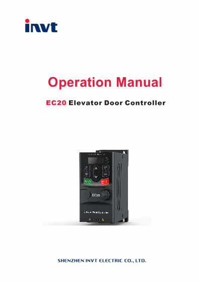
4.1 Keypad introduction
The keypad is used to control EC20 series controllers, read the state data and adjust parameters. If the
external keypad is needed, select the extension cable of the keypad.
Figure 4-1 Keypad
Note: The external keypads are optional (including the external keypads with and without the function of
parameter copying ).
Serial
No. Name Description
1 State LED
RUN/TUNE
LED off means that the inverter is in the stopping state;
LED blinking means the inverter is in the parameter
autotune state; LED on means the inverter is in the
running state.
FWD/REV
FED/REV LED
LED off means the inverter is in the forward rotation state;
LED on means the inverter is in the reverse rotation state
LOCAL/REMOT
LED for keypad operation, terminals operation and remote
communication control
LED off means that the inverter is in the keypad operation
state; LED blinking means the inverter is in the terminals
operation state; LED on means the inverter is in the
remote communication control state.
TRIP LED for faults
LED on when the inverter is in the fault state; LED off in

EC20 elevator door controller Keypad operation procedure
18
Serial
No. Name Description
normal state; LED blinking means the inverter is in the
pre-alarm state.
2 Unit LED
Mean the unit displayed currently
Hz Frequency unit
RPM Rotating speed unit
A Current unit
% Percentage
V Voltage unit
3
Code
displaying
zone
5-figure LED display displays various monitoring data and alarm code such as set
frequency and output frequency.
Displayed
word
Corresponding
word
Displayed
word
Corresponding
word
Displayed
word
Correspondin
g word
0 1 2
3 4 5
6 7 8
9 A B
C d E
F H I
L N n
o P r
S t U
v . -
4 Buttons
Program
ming key
Enter or escape from the first level menu and remove the
parameter quickly
Entry key
Enter the menu step-by-step
Confirm parameters
UP key Increase data or function code progressively
DOWN
key Decrease data or function code progressively
Right-shif
t key
Move right to select the displaying parameter circularly in
stopping and running mode.
Select the parameter modifying digit during the parameter
modification

EC20 elevator door controller Keypad operation procedure
19
Serial
No. Name Description
Run key
This key is used to operate on the inverter in key
operation mode
Stop/
Reset
key
This key is used to stop in running state. In speed control
mode, users need to press this key twice, the first is to
stop EC20 and the second is to restore EC20 to normal
state
Quick
key
The function of this key is confirmed by function code
P07.02.
5 Keypad port
External keypad port. When the external keypad with the function of parameter
copying is valid, the local keypad LED is off; When the external keypad without
the function of parameter copying is valid, the local and external keypad LEDs are
on.
Note: Only the external keypad which has the function of parameters copy owns
the function of parameters copy, other keypads do not have. (only for the inverters
≤2.2kW)
4.2 Keypad displaying
The keypad displaying state of EC20 series controllers is divided into stopping state parameter, running
state parameter, function code parameter editing state and fault alarm state and so on.
4.2.1 Displayed state of stopping parameter
When the controller is in the stopping state, the keypad will display stopping parameters which is shown
in figure 4-2.
In the stopping state, various kinds of parameters can be displayed. Select the parameters to be
displayed or not by P07.07. See the instructions of P07.07 for the detailed definition of each bit.
In the stopping state, there are 4 stopping parameters can be selected to be displayed or not. They are:
set frequency, bus voltage, input terminals state and output terminals state. P07.07 can select the
parameter to be displayed or not by bit and 》/SHIFT can shift the parameters form left to right,
QUICK/JOG(P07.02=2) can shift the parameters from right to left.
4.2.2 Displayed state of running parameters
After the controller receives valid running commands, the controller will enter into the running state and
the keypad will display the running parameters. RUN/TUNE LED on the keypad is on, while the
FWD/REV is determined by the current running direction which is shown as figure 4-2.
In the running state, there are 15 parameters can be selected to be displayed or not. They are: running

EC20 elevator door controller Keypad operation procedure
20
frequency, set frequency, bus voltage, output voltage, output current, rotating speed, output power,
output torque, input terminals state, output terminals state, percentage of motor overload, percentage of
controller overload, ramp given value, linear speed, AC input current. P07.05 and P07.06 can select the
parameter to be displayed or not by bit and 》/SHIFT can shift the parameters form left to right,
QUICK/JOG(P07.02=2) can shift the parameters from right to left.
4.1.3 Displayed state of fault
If the controller detects the fault signal, it will enter into the fault pre-alarm displaying state. The keypad
will display the fault code by flicking. The TRIP LED on the keypad is on, and the fault reset can be
operated by the STOP/RST on the keypad, control terminals or communication commands.
4.1.4 Displayed state of function codes editing
In the state of stopping, running or fault, press PRG/ESC to enter into the editing state (if there is a
password, see P07.00 ).The editing state is displayed on two classes of menu, and the order is: function
code group/function code number→function code parameter, press DATA/ENT into the displayed state
of function parameter. On this state, press DATA/ENT to save the parameters or press PRG/ESC to
escape.
Figure 4-2 Displayed state
4.3 Keypad operation
Operate the controller via operation panel. See the detailed structure description of function codes in the
brief diagram of function codes.
4.3.1 How to modify the function codes of the controller
The controller has three levels menu, which are:
1. Group number of function code (first-level menu)
2. Tab of function code (second-level menu)
3. Set value of function code (third-level menu)
Remarks: Press both the PRG/ESC and the DATA/ENT can return to the second-level menu from the
third-level menu. The difference is: pressing DATA/ENT will save the set parameters into the control
panel, and then return to the second-level menu with shifting to the next function code automatically;
while pressing PRG/ESC will directly return to the second-level menu without saving the parameters,

EC20 elevator door controller Keypad operation procedure
21
and keep staying at the current function code.
Under the third-level menu, if the parameter has no flickering bit, it means the function code cannot be
modified. The possible reasons could be:
1) This function code is not modifiable parameter, such as actual detected parameter, operation records
and so on;
2) This function code is not modifiable in running state, but modifiable in stop state.
Example: Set function code P00.01 from 0 to 1.
Figure 4-3 Sketch map of modifying parameters
4.3.2 How to set the password of the controller
EC20 series controllers provide password protection function to users. Set P7.00 to gain the password
and the password protection becomes valid instantly after quitting from the function code editing state.
Press PRG/ESC again to the function code editing state, “0.0.0.0.0” will be displayed. Unless using the
correct password, the operators cannot enter it.
Set P7.00 to 0 to cancel password protection function.
The password protection becomes effective instantly after retreating from the function code editing state.
Press PRG/ESC again to the function code editing state, “0.0.0.0.0” will be displayed. Unless using the
correct password, the operators cannot enter it.
Figure 4-4 Sketch map of password setting
4.3.3 How to watch the controller state through function codes
EC20 series controllers provide group P17 as the state inspection group. Users can enter into P17
directly to watch the state.

EC20 elevator door controller Keypad operation procedure
22
Figure 4-5 Sketch map of state watching

EC20 elevator door controller Function parameters
23
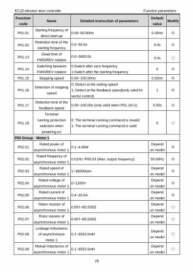
5 Function parameters
The function parameters of EC20 controllers have been divided into 30 groups (P00~P29) according to
the function. Each function group contains certain function codes applying 3-level menus. For example,
“P08.08” means the eighth function code in the P8 group function, P29 group is factory reserved, and
users are forbidden to access these parameters.
For the convenience of function codes setting, the function group number corresponds to the first level
menu, the function code corresponds to the second level menu and the function code corresponds to the
third level menu.
1. Below is the instruction of the function lists:
The first line “Function code”: codes of function parameter group and parameters;
The second line “Name”: full name of function parameters;
The third line “Detailed instruction of parameters”: detailed instruction of the function parameters;
The fourth line “Default value”: the original factory values of the function parameter;
The fifth line “Modify”: the modifying character of function codes (the parameters can be modified or not
and the modifying conditions), below is the instruction:
“”: means the set value of the parameter can be modified on stop and running state;
“”: means the set value of the parameter cannot be modified on the running state;
“”: means the value of the parameter is the real detection value which cannot be modified.
(The controller has limited the automatic inspection of the modifying character of the parameters to help
users avoid mismodifying)
2. “Parameter radix” is decimal (DEC), if the parameter is expressed by hex, then the parameter is
separated from each other when editing. The setting range of certain bits are 0~F (hex).
3. “Default value” means the function parameter will restore to the default value during default
parameters restoring. But the detected parameter or recorded value will not be restored.
4. For a better parameter protection, the controller provides password protection to the parameters. After
setting the password (set P07.00 to any non-zero number), the system will come into the state of
password verification firstly after the user press PRG/ESC to come into the function code editing state.
And then “0.0.0.0.0.” will be displayed. Unless the user input right password, they cannot enter into the
system. For the factory setting parameter zone, it needs correct factory password (remind that the users
can not modify the factory parameters by themselves, otherwise, if the parameter setting is incorrect,
damage to the controller may occur). If the password protection is unlocked, the user can modify the
password freely and the controller will work as the last setting one. When P07.00 is set to 0, the
password can be canceled. If P07.00 is not 0 during powering on, then the parameter is protected by the
password. When modify the parameters by serial communication, the function of the password follows
the above rules, too.
Note: The controller has carried out automatic inspection restraining on the modify attribute of the
parameters to avoid wrong modifying.

EC20 elevator door controller Function parameters
24
Function
code Name Detailed instruction of parameters
Default
value Modify
P00 Group Basic function group
P00.00 Speed control mode 1: SVC
2: SPWM 2
P00.01 OPEN/CLOSE control
mode
0: Speed control mode
1: Distance control mode 1 (need limit switch)
2: Distance control mode 2
0
P00.02 Elevator door control
mode
0: Keypad control mode (general inverter mode)
1: Terminal control mode (LED flickering)
2: Manual commissioning mode (FWD/REV
command by keypad)
3: Auto-displaying mode
4: Communication control mode (CAN
communication LED on)
5: Reserved
0
P00.03 Max. output frequency P00.04~250.00Hz (250.00Hz) 50.00Hz
P00.04 Upper limit of the
running frequency P00.05~P00.03 (Max. output frequency) 50.00Hz
P00.05 Lower limit of the
running frequency
0.00Hz~P00.04 (Upper limit of the running
frequency) 0.00Hz
P00.06 Keypad set frequency 0.00Hz~P00.03 (Max. output frequency) 10.00Hz
P00.07 ACC time 1 0.0~3600.0s 0.5s
P00.08 DEC time 1 0.0~3600.0s 0.5s
P00.09 Running direction
selection
0: Runs at the default direction
1: Runs at the opposite direction
2: Reserved
0
P00.10 Carrier frequency
setting 1.0~15.0kHz
Depend
on model
P00.11 Motor parameter
autotuning
0: No operation
1: Rotation autotuning
2: Static autotuning 1 (autotune totally)
3: Static autotuning 2 (autotune partially)
Note: Valid in general inverter mode (P00.02=0)
0
P00.12 AVR function
selection
0:Invalid
1:Valid during the whole procedure 1
P00.13 Function
restore parameter
0:No operation
1:Restore the default value
2:Clear fault records
0
P01 Group Start-up and stop control
EC20 elevator door controller Function parameters
25
Function
code Name Detailed instruction of parameters
Default
value Modify
P01.01 Starting frequency of
direct start-up 0.00~50.00Hz 0.30Hz
P01.02 Retention time of the
starting frequency 0.0~50.0s 0.0s
P01.13 Dead time of
FWD/REV rotation 0.0~3600.0s 0.0s
P01.14 Switching between
FWD/REV rotation
0:Switch after zero frequency
1:Switch after the starting frequency 0
P01.15 Stopping speed 0.00~100.00Hz 0.50Hz
P01.16 Detection of stopping
speed
0: Detect at the setting speed
1: Detect at the feedback speed(only valid for
vector control)
1
P01.17 Detection time of the
feedback speed 0.00~100.00s (only valid when P01.16=1) 0.50s
P01.18
Terminal
running protection
selection when
powering on
0: The terminal running command is invalid
1: The terminal running command is valid 0
P02 Group Motor 1
P02.01 Rated power of
asynchronous motor 1 0.1~4.0kW
Depend
on model
P02.02 Rated frequency of
asynchronous motor 1 0.01Hz~P00.03 (Max. output frequency) 50.00Hz
P02.03 Rated speed of
asynchronous motor 1 1~36000rpm
Depend
on model
P02.04 Rated voltage of
asynchronous motor 1 0~1200V
Depend
on model
P02.05 Rated current of
asynchronous motor 1 0.4~20.0A
Depend
on model
P02.06 Stator resistor of
asynchronous motor 1 0.001~65.535Ω
Depend
on model
P02.07 Rotor resistor of
asynchronous motor 1 0.001~65.535Ω
Depend
on model
P02.08
Leakage inductance
of asynchronous
motor 1
0.1~6553.5mH Depend
on model
P02.09 Mutual inductance of
asynchronous motor 1 0.1~6553.5mH
Depend
on model

EC20 elevator door controller Function parameters
26
Function
code Name Detailed instruction of parameters
Default
value Modify
P02.10 Non-load current of
asynchronous motor 1 0.1~6553.5A
Depend
on model
P02.11
Magnetic saturation
coefficient 1 for the
iron core of AM1
0.0~100.0% 80.0%
P02.12
Magnetic saturation
coefficient 2 for the
iron core of AM1
0.0~100.0% 68.0%
P02.13
Magnetic saturation
coefficient 3 for the
iron core of AM1
0.0~100.0% 57.0%
P02.14
Magnetic saturation
coefficient 4 for the
iron core of AM1
0.0~100.0% 40.0%
P02.26 Motor 1 overload
protection selection
0: No protection
1: Common motor (with low speed
compensation)
2: Frequency conversion motor (without low
speed compensation)
2
P02.27
Motor 1 overload
protection
coefficient
20.0%~120.0% 100.0%
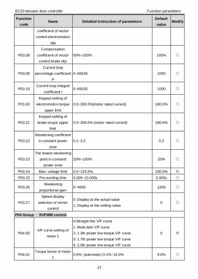
P03 Group Vector control
P03.00 Speed loop
proportional gain1 0~200.0 10.0
P03.01 Speed loop integral
time1 0.000~10.000s 0.200s
P03.02 Low switching
frequency 0.00Hz~P03.05 5.00Hz
P03.03 Speed loop
proportional gain 2 0~200.0 10.0
P03.04 Speed loop integral
time 2 0.000~10.000s 0.200s
P03.05 High switching
frequency P03.02~P00.03 (Max. output frequency) 10.00Hz
P03.06 Speed loop output
filter 0~8 (corresponds to 0~2^8/10ms) 0
P03.07 Compensation 50%~200% 100%
EC20 elevator door controller Function parameters
27
Function
code Name Detailed instruction of parameters
Default
value Modify
coefficient of vector
control electromotion
slip
P03.08
Compensation
coefficient of vector
control brake slip
50%~200% 100%
P03.09
Current loop
percentage coefficient
P
0~65535 1000
P03.10 Current loop integral
coefficient I 0~65535 1000
P03.20
Keypad setting of
electromotion torque
upper limit
0.0~300.0%(motor rated current) 180.0%
P03.21
Keypad setting of
brake torque upper
limit
0.0~300.0% (motor rated current) 180.0%
P03.22
Weakening coefficient
in constant power
zone
0.1~2.0 0.3
P03.23
The lowest weakening
point in constant
power zone
10%~100% 20%
P03.24 Max. voltage limit 0.0~120.0% 100.0%
P03.25 Pre-exciting time 0.000~10.000s 0.300s
P03.26 Weakening
proportional gain 0~4000 1200
P03.27
Speed display
selection of vector
control
0: Display at the actual value
1: Display at the setting value 0
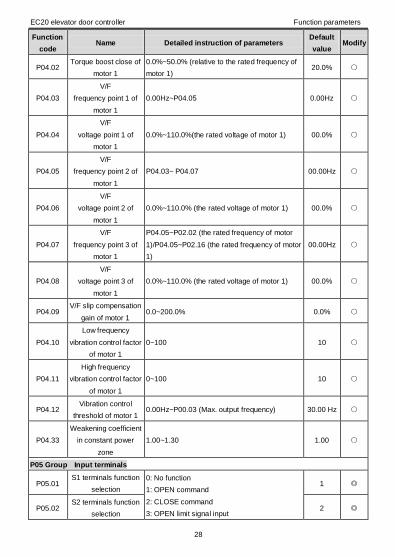
P04 Group SVPWM control
P04.00 V/F curve setting of
motor 1
0:Straight line V/F curve
1: Multi-dots V/F curve
2: 1.3th power low torque V/F curve
3: 1.7th power low torque V/F curve
4: 2.0th power low torque V/F curve
0
P04.01 Torque boost of motor
1 0.0%: (automatic) 0.1%~10.0% 9.0%
EC20 elevator door controller Function parameters
28
Function
code Name Detailed instruction of parameters
Default
value Modify
P04.02 Torque boost close of
motor 1
0.0%~50.0% (relative to the rated frequency of
motor 1) 20.0%
P04.03
V/F
frequency point 1 of
motor 1
0.00Hz~P04.05 0.00Hz
P04.04
V/F
voltage point 1 of
motor 1
0.0%~110.0%(the rated voltage of motor 1) 00.0%
P04.05
V/F
frequency point 2 of
motor 1
P04.03~ P04.07 00.00Hz
P04.06
V/F
voltage point 2 of
motor 1
0.0%~110.0% (the rated voltage of motor 1) 00.0%
P04.07
V/F
frequency point 3 of
motor 1
P04.05~P02.02 (the rated frequency of motor
1)/P04.05~P02.16 (the rated frequency of motor
1)
00.00Hz
P04.08
V/F
voltage point 3 of
motor 1
0.0%~110.0% (the rated voltage of motor 1) 00.0%
P04.09 V/F slip compensation
gain of motor 1 0.0~200.0% 0.0%
P04.10
Low frequency
vibration control factor
of motor 1
0~100 10
P04.11
High frequency
vibration control factor
of motor 1
0~100 10
P04.12 Vibration control
threshold of motor 1 0.00Hz~P00.03 (Max. output frequency) 30.00 Hz
P04.33
Weakening coefficient
in constant power
zone
1.00~1.30 1.00
P05 Group Input terminals
P05.01 S1 terminals function
selection
0: No function
1: OPEN command
2: CLOSE command
3: OPEN limit signal input
1
P05.02 S2 terminals function
selection 2

EC20 elevator door controller Function parameters
29
Function
code Name Detailed instruction of parameters
Default
value Modify
P05.03 S3 terminals function
selection
4: CLOSE limit signal input
5: OPEN speed switching input
6: CLOSE speed switching input
7: Safety sensor input
8: Emergency stop signal input
9~10: Reserved
3
P05.04 S4 terminals function
selection 4
P05.05 S5 terminals function
selection 7
P05.06 S6 terminals function
selection 5
P05.07 S7 terminals function
selection 6
P05.10 Polarity selection of
the input terminals 0x000~0xFF 0x6C
P05.11 Switch filter time 0.000~1.000s 0.010s
P05.14 S1 terminal switching
on delay time 0.000~50.000s 0.000s
P05.15
S1
terminal switching off
delay time
0.000~50.000s 0.000s
P05.16 S2 terminal switching
on delay time 0.000~50.000s 0.000s
P05.17
S2
terminal switching off
delay time
0.000~50.000s 0.000s
P05.18 S3 terminal switching
on delay time 0.000~50.000s 0.000s
P05.19
S3
terminal switching off
delay time
0.000~50.000s 0.000s
P05.20 S4 terminal switching
on delay time 0.000~50.000s 0.000s
P05.21
S4
terminal switching off
delay time
0.000~50.000s 0.000s
P05.22
S5
terminal switching on
delay time
0.000~50.000s 0.000s
P05.23 S5
terminal switching off 0.000~50.000s 0.000s
EC20 elevator door controller Function parameters
30
Function
code Name Detailed instruction of parameters
Default
value Modify
delay time
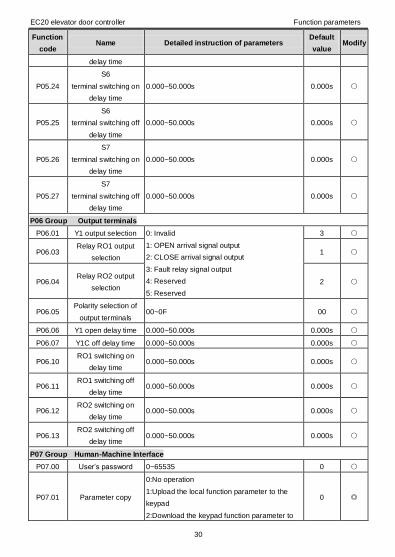
P05.24
S6
terminal switching on
delay time
0.000~50.000s 0.000s
P05.25
S6
terminal switching off
delay time
0.000~50.000s 0.000s
P05.26
S7
terminal switching on
delay time
0.000~50.000s 0.000s
P05.27
S7
terminal switching off
delay time
0.000~50.000s 0.000s
P06 Group Output terminals
P06.01 Y1 output selection 0: Invalid
1: OPEN arrival signal output
2: CLOSE arrival signal output
3: Fault relay signal output
4: Reserved
5: Reserved
3
P06.03 Relay RO1 output
selection 1
P06.04 Relay RO2 output
selection 2
P06.05 Polarity selection of
output terminals 00~0F 00
P06.06 Y1 open delay time 0.000~50.000s 0.000s
P06.07 Y1C off delay time 0.000~50.000s 0.000s
P06.10 RO1 switching on
delay time 0.000~50.000s 0.000s
P06.11 RO1 switching off
delay time 0.000~50.000s 0.000s
P06.12 RO2 switching on
delay time 0.000~50.000s 0.000s
P06.13 RO2 switching off
delay time 0.000~50.000s 0.000s
P07 Group Human-Machine Interface
P07.00 User’s password 0~65535 0
P07.01 Parameter copy
0:No operation
1:Upload the local function parameter to the
keypad
2:Download the keypad function parameter to
0
EC20 elevator door controller Function parameters
31
Function
code Name Detailed instruction of parameters
Default
value Modify
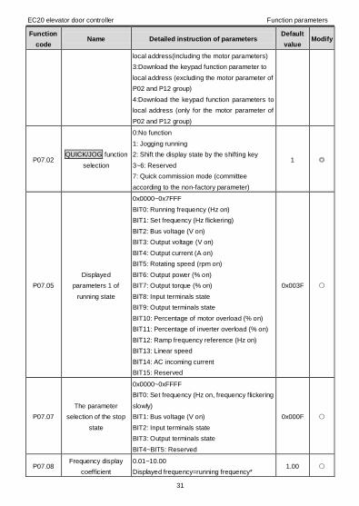
local address(including the motor parameters)
3:Download the keypad function parameter to
local address (excluding the motor parameter of
P02 and P12 group)
4:Download the keypad function parameters to
local address (only for the motor parameter of
P02 and P12 group)
P07.02 QUICK/JOG function
selection
0:No function
1: Jogging running
2: Shift the display state by the shifting key
3~6: Reserved
7: Quick commission mode (committee
according to the non-factory parameter)
1
P07.05
Displayed
parameters 1 of
running state
0x0000~0x7FFF
BIT0: Running frequency (Hz on)
BIT1: Set frequency (Hz flickering)
BIT2: Bus voltage (V on)
BIT3: Output voltage (V on)
BIT4: Output current (A on)
BIT5: Rotating speed (rpm on)
BIT6: Output power (% on)
BIT7: Output torque (% on)
BIT8: Input terminals state
BIT9: Output terminals state
BIT10: Percentage of motor overload (% on)
BIT11: Percentage of inverter overload (% on)
BIT12: Ramp frequency reference (Hz on)
BIT13: Linear speed
BIT14: AC incoming current
BIT15: Reserved
0x003F
P07.07
The parameter
selection of the stop
state
0x0000~0xFFFF
BIT0: Set frequency (Hz on, frequency flickering
slowly)
BIT1: Bus voltage (V on)
BIT2: Input terminals state
BIT3: Output terminals state
BIT4~BIT5: Reserved
0x000F
P07.08 Frequency display
coefficient
0.01~10.00
Displayed frequency=running frequency* 1.00

EC20 elevator door controller Function parameters
32
Function
code Name Detailed instruction of parameters
Default
value Modify
P07.08
P07.09 Speed display
coefficient
0.1~999.9%
Mechanical rotation speed=120*displayed
running frequency×P07.09/motor pole pairs
100.0%
P07.10 Linear speed
displayed coefficient
0.1~999.9%
Linear speed= Mechanical rotation
speed×P07.10
1.0%
P07.11 Rectifier bridge
module temperature 0~100.0
P07.12 Converter module
temperature 0~100.0
P07.13 Software version 1.00~655.35
P07.14 Local accumulative
running time 0~65535h
P07.17 Inverter type 0: G type
1: P type
P07.18 The rated power of
the inverter 0.4~3000.0kW
P07.19 The rated voltage of
the inverter 50~1200V
P07.20 The rated current of
the inverter 0.1~6000.0A
P07.21 Factory bar code 1 0x0000~0xFFFF
P07.22 Factory bar code 2 0x0000~0xFFFF
P07.23 Factory bar code 3 0x0000~0xFFFF
P07.24 Factory bar code 4 0x0000~0xFFFF
P07.25 Factory bar code 5 0x0000~0xFFFF
P07.26 Factory bar code 6 0x0000~0xFFFF
P07.27 Current fault type 0:No fault
1:Controller module U phase protection(OUt1)
2:Controller module V phase protection(OUt2)
3:Controller module W phase protection(OUt3)
4:OC1
5:OC2
6:OC3
7:OV1
8:OV2
9:OV3
P07.28 Previous fault type
P07.29 Previous 2 fault type
P07.30 Previous 3 fault type
P07.31 Previous 4 fault type
P07.32 Previous 5 fault type

EC20 elevator door controller Function parameters
33
Function
code Name Detailed instruction of parameters
Default
value Modify
10:UV
11:Motor overload(OL1)
12:The inverter overload(OL2)
13:Input side phase loss(SPI)
14:Output side phase loss(SPO)
15:Overheat of the rectifier module(OH1)
16:Overheat fault of the controller module(OH2)
17:External fault(EF)
18:485 communication fault(CE)
19:Current detection fault(ItE)
20:Motor antotune fault(tE)
21:EEPROM operation fault(EEP)
22:Reserved
23:Braking unit fault(bCE)
24:Running time arrival(END)
25:Electrical overload(OL3)
26:PCE
27:UPE
28:DNE
29~30:Reserved
31:CAN communication fault(E-CAN)
32~35:Reserved
36:Underload fault(LL)
37:Encoder offline fault(ENC1O)
38:Encoder reverse direction(ENC1D)
39:Limit switch signal exception(E_ds)
P07.33 Current fault running
frequency 0.00Hz
P07.34
Ramp reference
frequency at current
fault
0.00Hz
P07.35 Output voltage at the
current fault 0V
P07.36 Output current at the
current fault 0.0A
P07.37 Current bus voltage at
the current fault 0.0V
P07.38 The Max. temperature
at the current fault 0.0
EC20 elevator door controller Function parameters
34
Function
code Name Detailed instruction of parameters
Default
value Modify
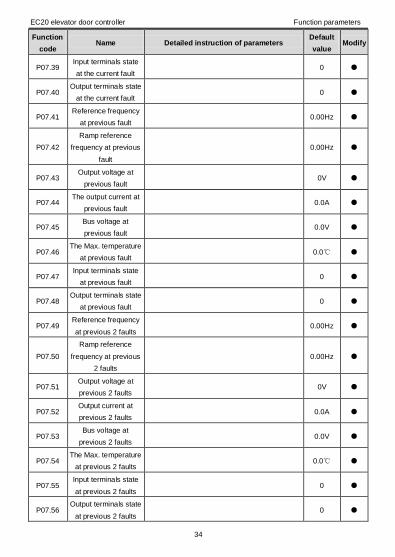
P07.39 Input terminals state
at the current fault 0
P07.40 Output terminals state
at the current fault 0
P07.41 Reference frequency
at previous fault 0.00Hz
P07.42
Ramp reference
frequency at previous
fault
0.00Hz
P07.43 Output voltage at
previous fault 0V
P07.44 The output current at
previous fault 0.0A
P07.45 Bus voltage at
previous fault 0.0V
P07.46 The Max. temperature
at previous fault 0.0
P07.47 Input terminals state
at previous fault 0
P07.48 Output terminals state
at previous fault 0
P07.49 Reference frequency
at previous 2 faults 0.00Hz
P07.50
Ramp reference
frequency at previous
2 faults
0.00Hz
P07.51 Output voltage at
previous 2 faults 0V
P07.52 Output current at
previous 2 faults 0.0A
P07.53 Bus voltage at
previous 2 faults 0.0V
P07.54 The Max. temperature
at previous 2 faults 0.0
P07.55 Input terminals state
at previous 2 faults 0
P07.56 Output terminals state
at previous 2 faults 0
EC20 elevator door controller Function parameters
35
Function
code Name Detailed instruction of parameters
Default
value Modify
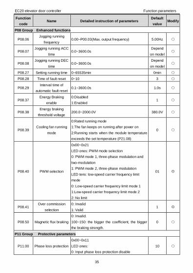
P08 Group Enhanced functions
P08.06 Jogging running
frequency 0.00~P00.03(Max. output frequency) 5.00Hz
P08.07 Jogging running ACC
time 0.0~3600.0s
Depend
on model
P08.08 Jogging running DEC
time 0.0~3600.0s
Depend
on model
P08.27 Setting running time 0~65535min 0min
P08.28 Time of fault reset 0~10 3
P08.29 Interval time of
automatic fault reset 0.1~3600.0s 1.0s
P08.37 Energy Braking
enable
0:Disabled
1:Enabled 1
P08.38 Energy braking
threshold voltage 200.0~2000.0V 380.0V
P08.39 Cooling fan running
mode
0:Rated running mode
1:The fan keeps on running after power on
2:Running starts when the module temperature
exceeds the set temperature (P21.08)
0
P08.40 PWM selection
0x00~0x21
LED ones: PWM mode selection
0: PWM mode 1, three-phase modulation and
two-modulation
1: PWM mode 2, three-phase modulation
LED tens: low-speed carrier frequency limit
mode
0: Low-speed carrier frequency limit mode 1
1:Low-speed carrier frequency limit mode 2
2: No limit
01
P08.41 Over commission
selection
0: Invalid
1: Valid 1
P08.50 Magnetic flux braking
0: Invalid.
100~150: the bigger the coefficient, the bigger
the braking strength.
0
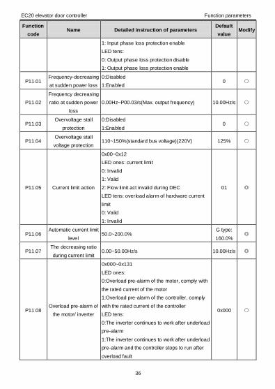
P11 Group Protective parameters
P11.00 Phase loss protection
0x00~0x11
LED ones:
0: Input phase loss protection disable
10
EC20 elevator door controller Function parameters
36
Function
code Name Detailed instruction of parameters
Default
value Modify
1: Input phase loss protection enable
LED tens:
0: Output phase loss protection disable
1: Output phase loss protection enable
P11.01 Frequency-decreasing
at sudden power loss
0:Disabled
1:Enabled 0
P11.02
Frequency decreasing
ratio at sudden power
loss
0.00Hz~P00.03/s(Max. output frequency) 10.00Hz/s
P11.03 Overvoltage stall
protection
0:Disabled
1:Enabled 0
P11.04 Overvoltage stall
voltage protection 110~150%(standard bus voltage)(220V) 125%
P11.05 Current limit action
0x00~0x12
LED ones: current limit
0: Invalid
1: Valid
2: Flow limit act invalid during DEC
LED tens: overload alarm of hardware current
limit
0: Valid
1: Invalid
01
P11.06 Automatic current limit
level 50.0~200.0%
G type:
160.0%
P11.07 The decreasing ratio
during current limit 0.00~50.00Hz/s 10.00Hz/s
P11.08 Overload pre-alarm of
the motor/ inverter
0x000~0x131
LED ones:
0:Overload pre-alarm of the motor, comply with
the rated current of the motor
1:Overload pre-alarm of the controller, comply
with the rated current of the controller
LED tens:
0:The inverter continues to work after underload
pre-alarm
1:The inverter continues to work after underload
pre-alarm and the controller stops to run after
overload fault
0x000
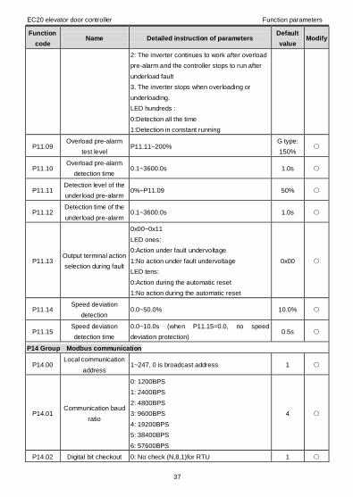
EC20 elevator door controller Function parameters
37
Function
code Name Detailed instruction of parameters
Default
value Modify
2: The inverter continues to work after overload
pre-alarm and the controller stops to run after
underload fault
3. The inverter stops when overloading or
underloading.
LED hundreds :
0:Detection all the time
1:Detection in constant running
P11.09 Overload pre-alarm
test level P11.11~200%
G type:
150%
P11.10 Overload pre-alarm
detection time 0.1~3600.0s 1.0s
P11.11 Detection level of the
underload pre-alarm 0%~P11.09 50%
P11.12 Detection time of the
underload pre-alarm 0.1~3600.0s 1.0s
P11.13 Output terminal action
selection during fault
0x00~0x11
LED ones:
0:Action under fault undervoltage
1:No action under fault undervoltage
LED tens:
0:Action during the automatic reset
1:No action during the automatic reset
0x00
P11.14 Speed deviation
detection 0.0~50.0% 10.0%
P11.15 Speed deviation
detection time
0.0~10.0s (when P11.15=0.0, no speed
deviation protection) 0.5s
P14 Group Modbus communication
P14.00 Local communication
address 1~247, 0 is broadcast address 1
P14.01 Communication baud
ratio
0: 1200BPS
1: 2400BPS
2: 4800BPS
3: 9600BPS
4: 19200BPS
5: 38400BPS
6: 57600BPS
4
P14.02 Digital bit checkout 0: No check (N,8,1)for RTU 1
EC20 elevator door controller Function parameters
38
Function
code Name Detailed instruction of parameters
Default
value Modify
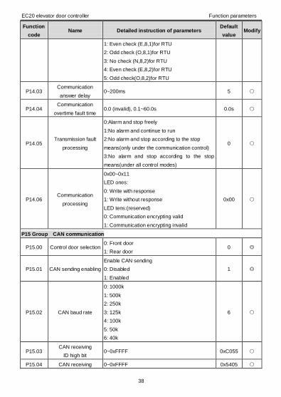
1: Even check (E,8,1)for RTU
2: Odd check (O,8,1)for RTU
3: No check (N,8,2)for RTU
4: Even check (E,8,2)for RTU
5: Odd check(O,8,2)for RTU
P14.03 Communication
answer delay 0~200ms 5
P14.04 Communication
overtime fault time 0.0 (invalid), 0.1~60.0s 0.0s
P14.05 Transmission fault
processing
0:Alarm and stop freely
1:No alarm and continue to run
2:No alarm and stop according to the stop
means(only under the communication control)
3:No alarm and stop according to the stop
means(under all control modes)
0
P14.06 Communication
processing
0x00~0x11
LED ones:
0: Write with response
1: Write without response
LED tens:(reserved)
0: Communication encrypting valid
1: Communication encrypting invalid
0x00
P15 Group CAN communication
P15.00 Control door selection 0: Front door
1: Rear door 0
P15.01 CAN sending enabling
Enable CAN sending
0: Disabled
1: Enabled
1
P15.02 CAN baud rate
0: 1000k
1: 500k
2: 250k
3: 125k
4: 100k
5: 50k
6: 40k
6
P15.03 CAN receiving
ID high bit 0~0xFFFF 0xC055
P15.04 CAN receiving 0~0xFFFF 0x5405

EC20 elevator door controller Function parameters
39
Function
code Name Detailed instruction of parameters
Default
value Modify
ID low bit
P15.05 CAN sending
ID high bit 0~0xFFFF 0xC055
P15.06 CAN sending
ID low bit 0~0xFFFF 0x5507
P15.08 CAN communication
cycle 0~500ms 100
P15.09 Communication
overtime fault time 0.0 (invalid), 0.1~60.0s 0.0s
P17 Group State view
P17.00 Setting frequency 0.00Hz~P00.03 0.00Hz
P17.01 Output frequency 0.00Hz~P00.03 0.00Hz
P17.02 Ramp reference
frequency 0.00Hz~P00.03 0.00Hz
P17.03 Output voltage 0~1200V 0V
P17.04 Output current 0.0~3000.0A 0.0A
P17.05 Motor speed 0~65535RPM 0RPM
P17.06 Torque current -3000.0~3000.0A 0.0A
P17.07 Magnetized current -3000.0~3000.0A 0.0A
P17.08 Motor power -300.0~300.0% (relative to the rated power of
the motor) 0.0%
P17.09 Output torque -250.0~250.0% 0.0%
P17.10 The motor frequency
evaluation 0.00~P00.03 0.00Hz
P17.11 DC bus voltage 0.0~2000.0V 0V
P17.12 Switch input terminals
state 0000~00FF 0
P17.13 Switch output
terminals state 0000~000F 0
P17.14 Digital adjustment 0.00Hz~P00.03 0.00V
P17.15 Torque reference -300.0%~300.0% (motor rated current) 0.0%

EC20 elevator door controller Function parameters
40
Function
code Name Detailed instruction of parameters
Default
value Modify
P17.23 Door width pulse
counting high bit Door width pulse counting=door width pulse
counting high bit*10000+door width pulse
counting low bit
0
P17.24 Door width pulse
counting low bit 0
P17.28 ASR controller output -300.0%~300.0% (motor rated current) 0.0%
P17.32 Magnetic flux linkage 0.0%~200.0% 0.0%
P17.33 Exciting current
reference -3000.0~3000.0A 0.0A
P17.34 Torque current
reference -3000.0~3000.0A 0.0A
P17.35 AC input current 0.0~5000.0A 0.0A
P17.36 Output torque -3000.0Nm~3000.0Nm 0.0Nm
P17.37 Motor overload
counting 0~100 (OL1 when 100) 0
P17.38 Encoder actual
frequency
Positive when the motor runs forward, negative
when the motor runs reversely
-3276.8~3276.7Hz
0
P17.39 Count value of
encoder position
1 circle count value of encoder pulse, 4
fold-frequency
0-65535
0
P17.40
High bit of
accumulated count
value of encoder
pulse Accumulated count value of encoder
pulse=P17.40*10000+P17.41
0
P17.41
Low bit of
accumulated count
value of encoder
pulse
0
P18 Group OPEN control
P18.00 OPEN speed setting 1 0.00Hz~P00.03 5.00Hz
P18.01 OPEN ACC/DEC time
1 0.1s~1000.0s 2.0s
P18.02 OPEN speed setting 2 0.00Hz~P00.03 12.00Hz
P18.03 OPEN ACC/DEC time
2 0.1s~1000.0s 2.0s

EC20 elevator door controller Function parameters
41
Function
code Name Detailed instruction of parameters
Default
value Modify
P18.04 OPEN speed setting 3 0.00Hz~P00.03 20.00Hz
P18.05 OPEN ACC/DEC time
3 0.1s~1000.0s 2.0s
P18.06 OPEN speed setting 4 0.00Hz~P00.03 4.00Hz
P18.07 OPEN ACC/DEC time
4 0.1s~1000.0s 2.0s
P18.08 OPEN speed setting 5 0.00Hz~P00.03 3.00Hz
P18.09 OPEN ACC/DEC time
5 0.1s~1000.0s 1.6s
P18.10 OPEN hold wait time 0.1s~1000.0s 1.0s
P18.11 OPEN hold waiting
speed 0.00Hz~P00.03 2.5Hz
P18.12 OPEN arrival hold
speed setting 0.00Hz~P00.03 1.50Hz
P18.13 OPEN arrival hold
torque
0.0%~150.0%(Relative to the motor rated
current in VF mode; relative to the motor rated
torque in vector mode)
60.0%
P18.14 OPEN obstruction
torque
0.0%~150.0%(Relative to the motor rated
current in VF mode; relative to the motor rated
torque in vector mode)
90.0%
P18.15 OPEN obstruction
judgment time 0.000s~10.000s 0.000s
P18.16 CLOSE limit signal
separation timing 0.1s~1000.0s 0.0s
P18.17 OPEN speed change
arrival timing 0.1s~1000.0s 0.0s
P18.18 OPEN ACC/DEC
selection
0: Linear
1: S curve 1
P18.19 OPEN S curve start
time 0.0~20.0s 0.2s
P18.20 OPEN S curve end
time 0.0~20.0s 0.2s
P19 Group CLOSE control
P19.00 CLOSE speed setting
1 0.00Hz~P00.03 5.00Hz
P19.01 CLOSE ACC/DEC
time 1 0.1s~1000.0s 1.0s
P19.02 CLOSE speed setting 0.00Hz~P00.03 14.00Hz

EC20 elevator door controller Function parameters
42
Function
code Name Detailed instruction of parameters
Default
value Modify
2
P19.03 CLOSE ACC/DEC
time 2 0.1s~1000.0s 2.0s
P19.04 CLOSE speed setting
3 0.00Hz~P00.03 18.00Hz
P19.05 CLOSE ACC/DEC
time 3 0.1s~1000.0s 3.0s
P19.06 CLOSE speed setting
4 0.00Hz~P00.03 3.00Hz
P19.07 CLOSE ACC/DEC
time 4 0.1s~1000.0s 1.5s
P19.08 CLOSE speed setting
5 0.00Hz~P00.03 0.60Hz
P19.09 CLOSE ACC/DEC
time 5 0.1s~1000.0s 40.0s
P19.10 CLOSE hold wait time 0.1s~1000.0s 1.0s
P19.11 CLOSE hold waiting
speed 0.00Hz~P00.03 0.6Hz
P19.12 CLOSE speed change
arrival timing 0.1s~1000.0s 0.0s
P19.13 CLOSE arrival hold
speed setting 0.00Hz~P00.03 0.6Hz
P19.14 CLOSE arrival hold
torque
0.0%~150.0%(Relative to the motor rated
current in VF mode; relative to the motor rated
torque in vector mode)
60.0%
P19.15 CLOSE obstruction
torque
0.0%~150.0%(Relative to the motor rated
current in VF mode; relative to the motor rated
torque in vector mode)
70.0%
P19.16 CLOSE obstruction
judgment time 0.000s~10.000s 0.000s
P19.18 OPEN limit signal
separation timing 0.1s~1000.0s 0.0s
P19.19 CLOSE overtime
judgment time 0.1s~1000.0s 0.0
P19.20
CLOSE obstruction
judgment slip (low
speed)
When the slip ratio is smaller than the judgment
slip, the obstruction signal becomes valid.
Slip=detection frequency/reference frequency
No detection when the detection time is 0
50.0%
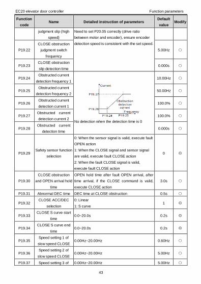
P19.21 CLOSE obstruction 70.0%
EC20 elevator door controller Function parameters
43
Function
code Name Detailed instruction of parameters
Default
value Modify
judgment slip (high
speed)
Need to set P20.05 correctly (drive ratio
between motor and encoder), ensure encoder
detection speed is consistent with the set speed.
P19.22
CLOSE obstruction
judgment switch
frequency
5.00Hz
P19.23 CLOSE obstruction
slip detection time 0.000s
P19.24 Obstructed current
detection frequency 1
No detection when the detection time is 0
10.00Hz
P19.25 Obstructed current
detection frequency 2 50.00Hz
P19.26 Obstructed current
detection current 1 100.0%
P19.27 Obstructed current
detection current 2 100.0%
P19.28 Obstructed current
detection time 0.000s
P19.29 Safety sensor function
selection
0: When the sensor signal is valid, execute fault
OPEN action
1: When the CLOSE signal and sensor signal
are valid, execute fault CLOSE action
2: When the fault CLOSE signal is valid,
execute fault CLOSE action
0
P19.30
CLOSE obstruction
and OPEN arrival hold
time
OPEN hold time after fault OPEN arrival, after
time arrival, if the CLOSE command is valid,
execute CLOSE action
3.0s
P19.31 Abnormal DEC time DEC time at CLOSE obstruction 0.5s
P19.32 CLOSE ACC/DEC
selection
0: Linear
1: S curve 1
P19.33 CLOSE S curve start
time 0.0~20.0s 0.2s
P19.34 CLOSE S curve end
time 0.0~20.0s 0.2s
P19.35 Speed setting 1 of
slow speed CLOSE 0.00Hz~20.00Hz 0.60Hz
P19.36 Speed setting 2 of
slow speed CLOSE 0.00Hz~20.00Hz 5.00Hz
P19.37 Speed setting 3 of 0.00Hz~20.00Hz 5.00Hz

EC20 elevator door controller Function parameters
44
Function
code Name Detailed instruction of parameters
Default
value Modify
slow speed CLOSE
P19.38 Speed setting 4 of
slow speed CLOSE 0.00Hz~20.00Hz 5.00Hz
P19.39 Speed setting 5 of
slow speed CLOSE 0.00Hz~20.00Hz 2.00Hz
P20 Group Distance control
P20.00 Door width autotuning
0: Disabled
1: Enabled, in manual commissioning mode of
elevator door
0
P20.01 Encoder pulse
number 0-60000 1024
P20.02 Encoder direction 0: Forward
1: Reverse 0
P20.03 Encoder offline
detection time 0.0~10.0s 1.0s
P20.04 Encoder reverse
detection time 0.0~100.0s 0.8s
P20.05 Speed ratio between
motor and encoder
When the encoder is not installed on the motor
shaft and the drive ratio is not 1, need to set the
parameter.
Setting range: 0.001~65.535
1.000
P20.06 Door width autotuning
speed 0.00~20.00Hz 3.00Hz
P20.07 High bit of door width
pulse number 0~9999 0
P20.08 Low bit of door width
pulse number 0~9999 0
P20.09 CLOSE arrival
position 0.0%~10.0% (door width) 3.0%
P20.10 OPEN speed change
position 1 0.0%~30.0% (door width) 10.0%
P20.11 OPEN speed change
position 2 20.0%~80.0% (door width) 30.0%
P20.12 OPEN speed change
position 3 80.0%~99.0% (door width) 70.0%
P20.13 OPEN speed change
position 4 80.0%~99.0% (door width) 90.0%
P20.14 OPEN arrival position 90.0%~100.0% (door width) 97.0%
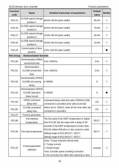
EC20 elevator door controller Function parameters
45
Function
code Name Detailed instruction of parameters
Default
value Modify
P20.15 CLOSE speed change
position 1 80.0%~99.0% (door width) 95.0%
P20.16 CLOSE speed change
position 2 60.0%~90.0% (door width) 75.0%
P20.17 CLOSE speed change
position 3 20.0%~80.0% (door width) 30.0%
P20.18 CLOSE speed change
position 4 20.0%~80.0% (door width) 10.0%
P20.19 Current pulse of door
position 0.0%~100.0% (door width)
P21 Group Demonstration function
P21.00 Demonstration OPEN
arrival hold time 0.0s~1000.0s 3.0s
P21.01
Demonstration
CLOSE arrival hold
time
0.0s~1000.0s 3.0s
P21.02
Demonstration OPEN/
CLOSE set running
times
0~65535 0
P21.03
Demonstration OPEN/
CLOSE operation
times record
0~65535 0
P21.04 OPEN command
delay time
Command delay valid time after OPEN/CLOSE
command is cancelled (only valid at arrival)
When set to 1000.0, valid all the time after the
command is cancelled
0.0
P21.05 CLOSE command
delay time 0.0
P21.07 Factory parameter
P21.08 Fan starting
temperature
The fan starts if the IGBT temperature is higher
than P21.08; the fan stops with a delay of 30
seconds if the IGBT temperature is lower than
P21.09. When P08.39 is 2, this control is valid.
Setting range of P21.08:0.0~50.0
Setting range of P21.09:0.0~50.0
50.0
P21.09 Fan stop temperature 50.0
P21.10 Control parameter
selection
Ones: Torque selection (Reserved)
0: Torque current
1: Actual torque
Tens: Encoder pulse counting correction
0: No correction for either door opening or door
0x1020
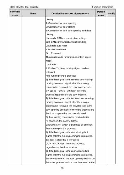
EC20 elevator door controller Function parameters
46
Function
code Name Detailed instruction of parameters
Default
value Modify
closing
1: Correction for door opening
2: Correction for door closing
3: Correction for both door opening and door
closing
Hundreds: CAN communication settings
Bit0: CAN communication fault handling
0: Disable auto reset
1: Enable auto reset
Bit1: Reserved
Thousands: Auto running(valid only in speed
mode)
0: Disable
1: Enable(Terminal running signal used as
criterion)
Auto running control process:
1) If the last signal is the terminal door-closing
running command signal, after the running
command is removed, the door is closed at a
low speed (P19.35-P19.39) in the entire
process, regardless of the door location.
2) If the last signal is the terminal door-opening
running command signal, after the running
command is removed, the elevator runs in the
door opening direction in the entire process and
the door is opened at the normal speed.
3) If no running command is received after
re-power on, the door will close.
2: Enable(Limit switch signal used as criterion)
Auto running control process:
1) If the last signal is the door closing limit
signal, after the running command is removed,
the door is closed at a low speed
(P19.35-P19.39) in the entire process,
regardless of the door location.
2) If the last signal is the door opening limit
signal, after the running command is removed,
the elevator runs in the door opening direction in
the entire process and the door is opened at the
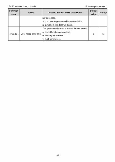
EC20 elevator door controller Function parameters
47
Function
code Name Detailed instruction of parameters
Default
value Modify
normal speed.
3) If no running command is received after
re-power on, the door will close.
P21.11 User mode switching
This parameter is used to switch the set values
of partial function parameters.
0: Factory parameters
1: DAT parameters
0
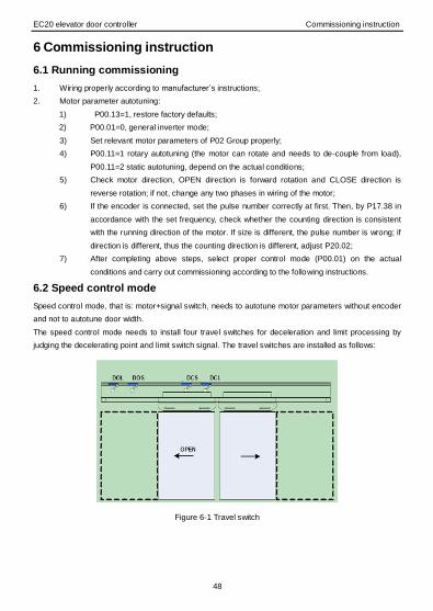
EC20 elevator door controller Commissioning instruction
48
6 Commissioning instruction
6.1 Running commissioning
1. Wiring properly according to manufacturer’s instructions;
2. Motor parameter autotuning:
1) P00.13=1, restore factory defaults;
2) P00.01=0, general inverter mode;
3) Set relevant motor parameters of P02 Group properly;
4) P00.11=1 rotary autotuning (the motor can rotate and needs to de-couple from load),
P00.11=2 static autotuning, depend on the actual conditions;
5) Check motor direction, OPEN direction is forward rotation and CLOSE direction is
reverse rotation; if not, change any two phases in wiring of the motor;
6) If the encoder is connected, set the pulse number correctly at first. Then, by P17.38 in
accordance with the set frequency, check whether the counting direction is consistent
with the running direction of the motor. If size is different, the pulse number is wrong; if
direction is different, thus the counting direction is different, adjust P20.02;
7) After completing above steps, select proper control mode (P00.01) on the actual
conditions and carry out commissioning according to the following instructions.
6.2 Speed control mode
Speed control mode, that is: motor+signal switch, needs to autotune motor parameters without encoder
and not to autotune door width.
The speed control mode needs to install four travel switches for deceleration and limit processing by
judging the decelerating point and limit switch signal. The travel switches are installed as follows:
Figure 6-1 Travel switch

EC20 elevator door controller Commissioning instruction
49
6.2.1 Wiring instruction in speed control mode
IM
U
N
V
W
L
PE
Me
ch
an
ica
l syste
m
CLOSE speed
change contact input
OPEN speed change
contact input
OPEN limit input
CLOSE limit input
S3
S4
S5
S6
S7
COM
AC
220V
Co
ntro
l
syste
m
OPEN command
CLOSE command
Y1
CME
EC20 elevator
door controller
Fault output
RO1A
RO1B
RO1C
Co
ntro
l syste
m
OPEN arrival output
RO2B
RO2C
RO2ACLOSE arrival output
Common terminal
Common terminal
Input ground
S1
S2
Safety sensor signal
input
Figure 6-2 Wiring instruction in speed control mode
6.2.2 Function parameters setting
Function
code Name Setting value
P00.00 Control mode 1: SVC
2: SVPWM (arbitrary setting)
P00.01 OPEN/CLOSE control mode 0: Speed control mode
P00.02 Elevator door control mode 1: Terminal control mode (LED flickering)
6.2.3 OPEN operation curve in speed control mode
OPEN limit signal
OPEN command
CLOSE limit signal
OPEN speed
change signal
CLOSE limit separation
timing (P18.16)
OPEN speed change
arrival timing (P18.17)
P18.01P18.00
P18.03 P18.02
P18.07P18.05
P18.04
P18.06
P18.09P18.08
P00.08
P18.11
P00.08
P18.12
Frequency
Time
OPEN hold
wait time
P18.10 OPEN hold torque
P18.13
Figure 6-3 OPEN operation curve in speed control mode

EC20 elevator door controller Commissioning instruction
50
Instruction of OPEN process in speed control mode:
1) When OPEN command is valid, the elevator door runs at the set speed P18.00 and the ACC
time is P18.01;
2) When CLOSE limit signal becomes from valid to invalid, shift to the set speed P18.02 and the
ACC time is P18.03; (if P18.16=0, go to the next step)
3) When CLOSE limit separation timing P18.14 arrives, shift to the set speed P18.04 and the ACC
time is P18.05;
4) When OPEN speed change signal is valid, shift to the set speed P18.06 and the ACC time is
P18.07; (if P18.17=0, go to the next step)
5) When OPEN speed change timing P18.15 arrives, shift to the set speed P18.08 and the ACC
time is P18.09;
6) When OPEN limit signal is valid, shift to the set speed P18.10 and the ACC time is P00.08;
7) When OPEN arrival wait time P18.10 reaches, shift to the stage of torque hold. The set speed is
P18.12 and the torque hold is P18.13.
6.2.4 CLOSE operation curve in speed control mode
CLOSE limit signal
CLOSE command
OPEN limit signal
CLOSE speed
change signal
OPEN limit separation
timing (P19.18)
CLOSE speed change
arrival timing (P19.12)
P19.01P19.00
P19.03 P19.02
P19.07P19.05
P19.04
P19.06
P19.09P19.08
P00.08
P19.11
P00.08
P19.13
Frequency
Time
CLOSE hold
wait time
P19.10 CLOSE
hold torque
P19.14
Figure 6-4 CLOSE operation curve in speed control mode
Instruction of CLOSE process in speed control mode:
1) When CLOSE command is valid, the elevator door runs at the set speed P19.00 and the ACC
time is P19.01;
2) When OPEN limit signal becomes from valid to invalid, shift to the set speed P19.02 and the
ACC time is P19.03; (if P19.18=0, go to the next step)
3) When OPEN limit separation timing P19.18 arrives, shift to the set speed P19.04 and the ACC
time is P19.05;
4) When CLOSE speed change signal is valid, shift to the set speed P19.06 and the ACC time is
P19.07; (if P19.12=0, go to the next step)
5) When CLOSE speed change timing P19.15 arrives, shift to the set speed P19.08 and the ACC
time is P19.09;
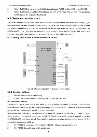
EC20 elevator door controller Commissioning instruction
51
6) When CLOSE limit signal is valid, shift to the set speed P19.10 and the ACC time is P00.08;
7) When CLOSE arrival wait time P19.10 reaches, shift to the stage of torque hold. The set speed
is P19.13 and the torque hold is P19.14.
6.3 Distance control mode 1
The distance control mode needs to install the encoder on the elevator door and the controller judges
door position by encoder counting. At first running, the mode needs autotuning door width pulse number
and realizes deceleration and arrival processing at decelerating point by setting the parameters of
OPEN/CLOSE curve. The distance control mode 1 needs to install OPEN/CLOSE limit switch and
autotunes door width pulse number between two switches at door width autotuning.
6.3.1 Wiring instruction in distance control mode 1
IM
U
N
V
W
L
PE
Me
ch
an
ica
l syste
m
OPEN limit input
CLOSE limit input
S3
S4
COM
AC
220V
Co
ntro
l
syste
m
OPEN command
CLOSE command
Y1
CME
EC20 elevator
door controller
Fault output
RO1A
RO1B
RO1C
Co
ntro
l syste
m
OPEN arrival output
RO2B
RO2C
RO2A CLOSE arrival output
Common terminal
Common terminal
Input ground
+12V
PGA
COM
PGB
IM
Encoder
Shielded layer
grounding
S1
S2
Figure 6-5 Wiring instruction in distance control mode 1
6.3.2 Encoder setting
1) Firm installation and reliable wiring;
2) Correct parameters setting, including pulse number and direction
Door width autotuning
The distance control mode needs door width autotuning before operation. In OPEN/CLOSE process
under distance control, record the running pulse number at real time and combine with the data of door
width pulse for OPEN/CLOSE arrival control and judgment.
During door width autotuning, the direction of the door will change automatically, so ensure personal
safety before any operation. Please make sure OPEN/CLOSE limit switch can work normally according
to OPEN/CLOSE limit signal arrival; if the switch is abnormal, the door width cannot be measured. The
steps of measuring door width are:
1) Set P00.01=1 (distance control mode 1), P00.02 = 2 (automatic control mode);
2) Set P20.00=1, enable door width autotuning;

EC20 elevator door controller Commissioning instruction
52
3) After keypad reference operation signal, door width autotuning starts. Carry out door width
pulse autotuning in the sequence of CLOSE->OPEN->CLOSE. After autotuning, door width
pulse number will be restored in P20.07 and P20.08.
Note: Select appropriate speed for door width autotuning, too large easy strike, too small lack of force.
Meanwhile, setting proper arrival torque detection (P18.14) can ensure the force is suitable for normal
operation of the elevator door and avoid it is too large to detect arrival.
6.3.3 Function parameters setting
Function
code Name Setting value
P00.00 Control mode 1: SVC
2: SVPWM (arbitrary setting)
P00.01 OPEN/CLOSE control mode 0: Distance control mode 1
P00.02 Elevator door control mode 1: Terminal control mode (LED flickering)
6.3.4 OPEN operation curve in distance control mode 1
OPEN limit
signal
OPEN
command
CLOSE limit
signal
Door position
P18.01P18.00
P18.03 P18.02
P18.07P18.05
P18.04
P18.06
P18.09P18.08
P00.08
P18.11
P00.08
P18.12
Frequency
Time
OPEN hold
wait time
P18.10 OPEN hold
torque
P18.13
100%
0%
P20.09 P20.10 P20.11 P20.12 P20.13 P20.14
Figure 6-6 OPEN operation curve in distance control mode 1
Instruction of OPEN process in distance control mode 1:
1) When OPEN command is valid, the elevator door runs at the set speed P18.00 and the ACC
time is P18.01;
2) When door position pulse number is larger than P20.10, shift to the set speed P18.02 and the
ACC time is P18.03;
3) When door position pulse number is larger than P20.11, shift to the set speed P18.04 and the
ACC time is P18.05;
4) When door position pulse number is larger than P20.12, shift to the set speed P18.06 and the
ACC time is P18.07;
5) When door position pulse number is larger than P20.13, shift to the set speed P18.08 and the
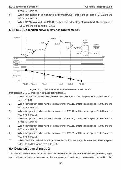
EC20 elevator door controller Commissioning instruction
53
ACC time is P18.09;
6) When door position pulse number is larger than P20.14, shift to the set speed P18.10 and the
ACC time is P00.08;
7) When OPEN arrival wait time P18.10 reaches, shift to the stage of torque hold. The set speed is
P18.12 and the torque hold is P18.13.
6.3.5 CLOSE operation curve in distance control mode 1
CLOSE limit
signal
CLOSE
command
OPEN
limit signal
Door position
P19.01P19.00
P19.03 P19.02
P19.07P19.05
P19.04
P19.06
P19.09P19.08
P00.08
P19.11
P00.08
P19.13
Frequency
Time
CLOSE
hold wait
time
P19.10CLOSE
hold torque
P19.14
100%
0%
P20.14 P20.15 P20.16 P20.17 P20.18 P20.09
Figure 6-7 CLOSE operation curve in distance control mode 1
Instruction of CLOSE process in distance control mode 1:
1) When CLOSE command is valid, the elevator door runs at the set speed P19.00 and the ACC
time is P19.01;
2) When door position pulse number is smaller than P20.15, shift to the set speed P19.02 and the
ACC time is P19.03;
3) When door position pulse number is smaller than P20.16, shift to the set speed P19.04 and the
ACC time is P19.05;
4) When door position pulse number is smaller than P20.17, shift to the set speed P19.06 and the
ACC time is P19.07;
5) When door position pulse number is smaller than P20.18, shift to the set speed P19.08 and the
ACC time is P19.09;
6) When door position pulse number is smaller than P20.09, shift to the set speed P19.10 and the
ACC time is P00.08;
7) When CLOSE arrival wait time P19.10 reaches, shift to the stage of torque hold. The set speed
is P19.13 and the torque hold is P19.14.
6.4 Distance control mode 2
The distance control mode needs to install the encoder on the elevator door and the controller judges
door position by encoder counting. At first operation, the mode needs autotuning door width pulse

EC20 elevator door controller Commissioning instruction
54
number and realizes deceleration and arrival processing at decelerating point by setting the parameters
of OPEN/CLOSE curve. The distance control mode 2 does not need to install OPEN/CLOSE limit switch
and autotunes door width pulse number between OPEN and CLOSE arrival at door width autotuning.
6.4.1 Wiring instruction in distance control mode 2
IM
U
N
V
W
L
PE
COM
AC
220V
Co
ntro
l
syste
m
OPEN command
CLOSE command
Y1
CME
EC20 elevator
door controller
Fault
output
RO1A
RO1B
RO1C
Co
ntro
l syste
m
OPEN arrival output
RO2B
RO2C
RO2A CLOSE arrival output
Common terminal
Common terminal
Input ground
+12V
PGA
COM
PGB
IM
Encoder
Shielded layer
grounding
S1
S2
Figure 6-8 Wiring instruction in distance control mode 2
6.4.2 Encoder setting
The same as distance control mode 1
6.4.3 Door width autotuning
Distance control mode 2 also needs to autotune door width at first. The limit switches are not installed,
the arrival is based on detecting arrival torque, so ensure there are no obstacles during door width
autotuning. Except that, mode 2 is the same with mode 1.
6.4.4 Function parameters setting
Function
code Name Setting value
P00.00 Control mode 1: SVC
2: SVPWM (set freely)
P00.01 OPEN/CLOSE control mode 0: Distance control mode 2
P00.02 Elevator door control mode 1: Terminal control mode (LED flickering)

EC20 elevator door controller Commissioning instruction
55
6.4.5 OPEN operation curve in distance control mode 2
OPEN
command
Door position
P18.01P18.00
P18.03 P18.02
P18.07P18.05
P18.04
P18.06
P18.09P18.08
P00.08
P18.11
P00.08
P18.12
Frequency
Time
OPEN hold
wait time
P18.10 OPEN hold
torque
P18.13
100%
0%
P20.09 P20.10 P20.11 P20.12 P20.13 P20.14
Figure 6-9 OPEN operation curve in distance control mode 2
Instruction of OPEN process in distance control mode 2:
1) When OPEN command is valid, the elevator door runs at the set speed P18.00 and the ACC
time is P18.01;
2) When door position pulse number is larger than P20.10, shift to the set speed P18.02 and the
ACC time is P18.03;
3) When door position pulse number is larger than P20.11, shift to the set speed P18.04 and the
ACC time is P18.05;
4) When door position pulse number is larger than P20.12, shift to the set speed P18.06 and the
ACC time is P18.07;
5) When door position pulse number is larger than P20.13, shift to the set speed P18.08 and the
ACC time is P18.09;
6) When door position pulse number is larger than P20.14, shift to the set speed P18.10 and the
ACC time is P00.08;
7) When OPEN arrival wait time P18.10 reaches, shift to the stage of torque hold. The set speed is
P18.12 and the torque hold is P18.13.

EC20 elevator door controller Commissioning instruction
56
6.4.6 CLOSE operation curve in distance control mode 2
CLOSE
command
Door position
P19.01P19.00
P19.03 P19.02
P19.07P19.05
P19.04
P19.06
P19.09P19.08
P00.08
P19.11
P00.08
P19.13
Frequency
Time
CLOSE hold
wait time
P19.10 CLOSE
hold torque
P19.14
100%
0%
P20.14 P20.15 P20.16 P20.17 P20.18 P20.09
Figure 6-10 CLOSE operation curve in distance control mode 2
Instruction of CLOSE process in distance control mode 2:
1) When CLOSE command is valid, the elevator door runs at the set speed P19.00 and the ACC
time is P19.01;
2) When door position pulse number is smaller than P20.15, shift to the set speed P19.02 and the
ACC time is P19.03;
3) When door position pulse number is smaller than P20.16, shift to the set speed P19.04 and the
ACC time is P19.05;
4) When door position pulse number is smaller than P20.17, shift to the set speed P19.06 and the
ACC time is P19.07;
5) When door position pulse number is smaller than P20.18, shift to the set speed P19.08 and the
ACC time is P19.09;
6) When door position pulse number is smaller than P20.09, shift to the set speed P19.10 and the
ACC time is P00.08;
7) When CLOSE arrival wait time P19.10 reaches, shift to the stage of torque hold. The set speed
is P19.13 and the torque hold is P19.14.
6.5 CLOSE obstruction
CLOSE obstruction refers to the following several states during CLOSE operation. For example, if light
screen (elevator safety protection device)/touch board signal is valid and the output torque is larger than
CLOSE obstruction torque, EC20 controller will re-open the door after CLOSE obstruction. There are
many ways to judge CLOSE obstruction, such as time, torque and slip (distance control mode), shown
as follows:
Current detection: by contrast of OPEN/CLOSE torque current and obstruction torque;
Slip detection: slip during OPEN/CLOSE operation (only valid in distance control mode)
Time detection: valid time of OPEN/CLOSE signal;

EC20 elevator door controller Commissioning instruction
57
Safety sensor detection: detect whether there is any obstacles by sensor.
6.5.1 CLOSE obstruction process
CLOSE
command
Frequency
Time
No
rma
l CL
OS
E
Ab
no
rma
l DE
C
Re
-OP
EN
OP
EN
arriv
al
ho
ld
No
rma
l CL
OS
E
CLOSE
obstruction
sign
Abnormal DEC time
(P19.31)
OPEN arrival hold time
(P21.00)
Figure 6-11 CLOSE obstruction
Note: In speed control mode, when CLOSE limit signal is valid, there will be no CLOSE obstruction
detection; in distance control mode, when the door position is larger than CLOSE arrival position, there
will be no CLOSE obstruction detection.
6.5.2 Common commissioning problems
1. Encoder offline fault (ENC1O): if the distance control mode 1 and 2 start, alarm “ENC1O”. Check
whether the cables of the encoder are connected, including encoder voltage signal, A and B pulse
signals.
2. Encoder reverse fault (ENC1D): if the distance control mode 1 and 2 start, alarm “ENC1D”. Check
whether the A and B signal cables are connected properly and ensure the A and B signals of the
encoder are connected to the A and B signals of the controller.
3. At CLOSE operation, the elevator door has crashes. Adjust the operation curves of the elevator door,
reduce CLOSE speed, P19.06 and P19.08.
4. Too large CLOSE obstruction torque (when obstructed, the thrust of the elevator door is so large that
passengers may be easily nipped by the door). In speed control mode, suggest judging CLOSE
obstruction by torque obstruction. When the obstruction torque is too large, adjust CLOSE obstruction
torque and CLOSE obstruction judgment time and reduce P19.15 and P19.16.
5. At CLOSE, the elevator door closes and then open: CLOSE obstruction misjudgment, increase time
and judgment coefficient (torque obstruction: P19.15, P19.16; slip obstruction: P19.20, P19.21,
P19.22, P19.23; current obstruction: P19.24, P19.25, P19.26, P19.27, P19.28)
6. The elevator door cannot open or close smoothly: the operation curves are set improperly. OPEN
stuck: adjust P18.00, P18.02, P18.04, P18.06, P18.08 and set speed continuously, neither too high
nor too low. CLOSE stuck: adjust P19.00, P19.02, P19.04, P19.06, P19.08 and set speed
continuously, neither too high nor too low.
7. There is gap after CLOSE arrival: increase P19.14 and arrival hold torque.

EC20 elevator door controller Fault
58
7 Fault
7.1 Fault prevention
The chapter contains preventive maintenance instructions of the controller.
7.1.1 Maintenance intervals
If installed in an appropriate environment, the controller requires very little maintenance. The table lists
the routine maintenance intervals recommended by INVT. For more information about maintenance,
please contact with us.
Checking Item Method Criterion
Ambient environment
Check the ambient temperature,
humidity and vibration and
ensure there is no dust, gas, oil
fog or water drop.
Visual examination
and instrument test
Conforming to the
manual
Ensure there are no tools or
other foreign or dangerous
objects.
Visual examination There are no tools or
dangerous objects.
Voltage Ensure the main circuit and
control circuit are normal.
Measure with
multimeter
Conforming to the
manual
Keypad
Ensure the display is clear
enough. Visual examination
The characters are
displayed normally.
Ensure the characters are
displayed totally. Visual examination
Conforming to the
manual
Main
circuit
For public
use
Ensure the screws are tightened
securely. Tighten up NA
Ensure there is no distortion,
crackles, damage or
color-changing caused by
overheat and aging to the
machine.
Visual examination NA
Ensure there is no dust or
dirtiness Visual examination
NA
Note: If the color of
copper blocks
changes, it does not
mean there is
something wrong
with the features.
Lead of
conductors
Ensure that there is no distortion
or color-changing caused by Visual examination NA
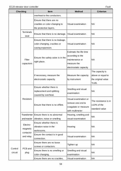
EC20 elevator door controller Fault
59
Checking Item Method Criterion
overheat to the conductors.
Ensure that there are no
crackles or color-changing to
the protective layers.
Visual examination NA
Terminals
seat Ensure that there is no damage. Visual examination NA
Filter
capacitors
Ensure that there is no leakage,
color-changing, crackles or
casing expansion.
Visual examination NA
Ensure the safety valve is in the
right place.
Estimate the life time
according to the
maintenance or
measure the
electrostatic capacity
NA
If necessary, measure the
electrostatic capacity.
Measure the capacity
by instrument
The capacity is
above or equal to
the original value
*0.85.
Resistors
Ensure whether there is
replacement and splitting
caused by overheat.
Smelling and visual
examination NA
Ensure that there is no offline.
Visual examination or
remove one end to
coagulate or measure
with multimeter
The resistance is in
±10% of the
standard value
Transformer
and reactor
Ensure there is no abnormal
vibration, noise or smelling
Hearing, smelling and
visual examination NA
Electro-
magnetic
contactor
and relay
Ensure whether there is
vibration noise in the
workrooms.
Hearing NA
Ensure the contact is in good
connection. Visual examination NA
Control
circuit
PCB and
plug
Ensure there are no loose
screws or contactors. Tighten up NA
Ensure there is no smelling or
color-changing.
Smelling and visual
examination NA
Ensure there are no crackles, Visual examination NA
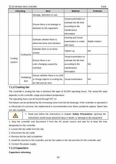
EC20 elevator door controller Fault
60
Checking Item Method Criterion
damage, distortion or rust.
Ensure there is no leakage or
distortion to the capacitors.
Visual examination or
estimate the life time
according to the
maintenance
information
NA
Cooling
system
Cooling fan
Estimate whether there is
abnormal noise and vibration.
Hearing and Visual
examination or rotate
with hand
Stable rotation
Estimate there is no loose
screws. Tighten up NA
Ensure there is no
color-changing caused by
overheat.
Visual examination or
estimate the life time
according to the
maintenance
information
NA
Ventilating
duct
Ensure whether there is no stuff
or foreign objects in cooling fan,
air inlet and air vent.
Visual examination NA
7.1.2 Cooling fan
The controller ’s cooling fan has a minimum life span of 25,000 operating hours. The actual life span
depends on the controller usage and ambient temperature.
The operating hours can be found through P07.14.
Fan failure can be predicted by the increasing noise from the fan bearings. If the controller is operated in
a critical part of a process, fan replacement is recommended once these symptoms appear. Spare fans
are also available.
Read and follow the instructions in chapter Safety Precautions. Ignoring the
instructions would cause physical injury or death, or damage to the equipment.
1. Stop the controller and disconnect it from the AC power source and wait for at least the time
designated on the controller.
2. Loosen the fan cable from the clip.
3. Disconnect the fan cable.
4. Remove the fan with screwdriver.
5. Install the new fan in the controller, put the fan cables in the clip and then fix the controller well.
6. Connect the power supply.
7.1.3 Capacitors
Capacitors reforming

EC20 elevator door controller Fault
61
The DC bus capacitors must be reformed according to the operation instruction if the controller has been
stored for a long time. The storing time is counted from the delivery date.
Time Operational principle
Storing time less than 1
year Operation without charging
Storing time 1-2 years Connect with the power for 1 hour before first ON command
Storing time 2-3 years
Use voltage-adjusting power supply to charge the controller
• charging 25% rated voltage for 30 minutes
• charging 50% rated voltage for 30 minutes
• charging 75% rated voltage for 30 minutes
• charging 100% rated voltage for 30 minutes
Storing time more than 3
years
Use voltage-adjusting power supply to charge the controller
• charging 25% rated voltage for 2 hours
• charging 50% rated voltage for 2 hours
• charging 75% rated voltage for 2 hours
• charging 100% rated voltage for 2 hours
Use voltage-adjusting power supply to charge the controller:
The right selection of the voltage-adjusting power supply depends on the supply power of the controller.
The single-phase 220V AC/2A voltage regulator is applied to single/three-phase 220V AC controller. The
single/three-phase controller can apply single-phase voltage-adjusting power supply for charging. All DC
bus capacitors can charge at the same time because there is one rectifier.
High-voltage controller needs enough voltage during charging. The small capacitor power (2A is enough)
can be used because the capacitor nearly does not need current when charging.
Change electrolytic capacitors
Read and follow the instructions in chapter Safety Precautions. Ignoring the
instructions would cause physical injury or death, or damage to the
equipment.
Change electrolytic capacitors if the working hours of electrolytic capacitors in the controller are above
35,000. Please contact with the local offices or dial our national service hotline (400-700-9997) for
detailed operation.
7.1.4 Power cable
Read and follow the instructions in chapter Safety Precautions. Ignoring the
instructions would cause physical injury or death, or damage to the
equipment.
1. Stop the drive and disconnect it from the power line. Wait for at least the time designated on the
controller.
2. Check the tightness of the power cable connections.
3. Connect the power supply.
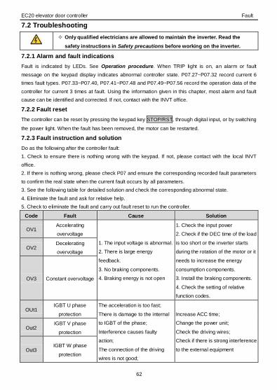
EC20 elevator door controller Fault
62
7.2 Troubleshooting
Only qualified electricians are allowed to maintain the inverter. Read the
safety instructions in Safety precautions before working on the inverter.
7.2.1 Alarm and fault indications
Fault is indicated by LEDs. See Operation procedure. When TRIP light is on, an alarm or fault
message on the keypad display indicates abnormal controller state. P07.27~P07.32 record current 6
times fault types. P07.33~P07.40, P07.41~P07.48 and P07.49~P07.56 record the operation data of the
controller for current 3 times at fault. Using the information given in this chapter, most alarm and fault
cause can be identified and corrected. If not, contact with the INVT office.
7.2.2 Fault reset
The controller can be reset by pressing the keypad key STOP/RST, through digital input, or by switching
the power light. When the fault has been removed, the motor can be restarted.
7.2.3 Fault instruction and solution
Do as the following after the controller fault:
1. Check to ensure there is nothing wrong with the keypad. If not, please contact with the local INVT
office.
2. If there is nothing wrong, please check P07 and ensure the corresponding recorded fault parameters
to confirm the real state when the current fault occurs by all parameters.
3. See the following table for detailed solution and check the corresponding abnormal state.
4. Eliminate the fault and ask for relative help.
5. Check to eliminate the fault and carry out fault reset to run the controller.
Code Fault Cause Solution
OV1 Accelerating
overvoltage
1. The input voltage is abnormal.
2. There is large energy
feedback.
3. No braking components.
4. Braking energy is not open
1. Check the input power
2. Check if the DEC time of the load
is too short or the inverter starts
during the rotation of the motor or it
needs to increase the energy
consumption components.
3. Install the braking components.
4. Check the setting of relative
function codes.
OV2 Decelerating
overvoltage
OV3 Constant overvoltage
OUt1 IGBT U phase
protection
The acceleration is too fast;
There is damage to the internal
to IGBT of the phase;
Interference causes faulty
action;
The connection of the driving
wires is not good;
Increase ACC time;
Change the power unit;
Check the driving wires;
Check if there is strong interference
to the external equipment
Out2 IGBT V phase
protection
Out3 IGBT W phase
protection

EC20 elevator door controller Fault
63
Code Fault Cause Solution
The grounding is not good
OC1 Accelerating
overcurrent
1. The acceleration or
deceleration is too fast.
2. The voltage of the grid is too
low.
3. The power of the inverter is
too low.
4. The load transients or is
abnormal.
5. The grounding is short
circuited or the output is phase
loss.
6. There is strong external
interference.
7. The overvoltage stall
protection is not open.
1. Increase the ACC/DEC time
2. Check the input power
3. Select the controller with a larger
power
4. Check if the load is short
circuited (the grounding short
circuited or the wire short circuited)
or the rotation is not smooth.
5. Check the output configuration.
6. Check if there is strong
interference.
7. Check the setting of relative
function codes.
OC2 Decelerating
overcurrent
OC3 Constant overcurrent
UV Bus undervoltage fault
1. The voltage of the power
supply is too low.
2. The overvoltage stall
protection is not open.
1. Check the input power of the
supply line.
2. Check the setting of relative
function codes.
OL1 Motor overload
The voltage of the power supply
is too low;
The setting of motor rated
current is incorrect;
The motor stall or load transients
is too strong
Check the power of the supply line;
Reset the rated current of the motor
Check the load and adjust the
torque lift
OL2 Inverter overload
The acceleration is too fast;
Reset the rotating motor;
The voltage of the power supply
is too low;
The load is too heavy;
The motor power is much larger
than load power
Increase the ACC time;
Avoid the restarting after stopping;
Check the power of the supply line;
Select an inverter with bigger
power;
Select a proper motor
SPI Input phase loss Large fluctuation Check input power;
Check installation distribution
SPO Output phase loss U, V, W phase loss output (or
three phases of the load are
Check the output distribution;
Check the motor and cable

EC20 elevator door controller Fault
64
Code Fault Cause Solution
seriously asymmetrical)
OH1 Rectifying module
overheat
Air duct jam or fan damage;
Ambient temperature is too high;
The time of overload running is
too long
Dredge the air duct or change the
fan;
Low the ambient temperature OH2 Converter module
overheat
EF External fault SI external fault input terminals
action Check the external device input
CE 485 communication
fault
The baud rate setting is
incorrect;
Fault occurs to the
communication wiring;
The communication address is
wrong;
There is strong interference to
the communication
Set proper baud rate;
Check the communication
connection distribution;
Set proper communication address;
Change or replace the connection
distribution or improve the
anti-interference capability
ItE Current detection fault
The connection of the control
board is not good;
Hoare component is broken;
The modifying circuit is abnormal
Check the connector and repatch;
Change the Hoare;
Change the main control board
tE Motor autotuning fault
The motor capacity does not
comply with the inverter
capacity;
The rated parameter of the
motor does not set correctly;
The offset between the
parameters from autotune and
the standard parameter is huge;
Autotune overtime
Change the inverter model;
Set the rated parameter according
to the motor name plate;
Empty the motor load and
reidentify;
Check the motor connection and
set the parameter;
Check if the upper limit frequency is
above 2/3 of the rated frequency
EEP EEPROM operation
fault
Error of controlling the write and
read of the parameters;
Damage to EEPROM
Press STOP/RST to reset;
Change the main control board
bcE Braking unit fault
Braking circuit fault or damage to
the braking pipes;
The external braking resistor is
not sufficient
Check the braking unit and change
new braking pipes;
Increase the braking resistor
END Running time arrival The actual running time of the
inverter is above the internal
Ask for the supplier and adjust the
setting running time
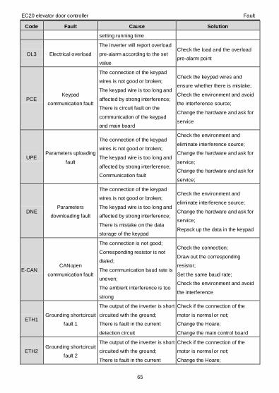
EC20 elevator door controller Fault
65
Code Fault Cause Solution
setting running time
OL3 Electrical overload
The inverter will report overload
pre-alarm according to the set
value
Check the load and the overload
pre-alarm point
PCE Keypad
communication fault
The connection of the keypad
wires is not good or broken;
The keypad wire is too long and
affected by strong interference;
There is circuit fault on the
communication of the keypad
and main board
Check the keypad wires and
ensure whether there is mistake;
Check the environment and avoid
the interference source;
Change the hardware and ask for
service
UPE Parameters uploading
fault
The connection of the keypad
wires is not good or broken;
The keypad wire is too long and
affected by strong interference;
Communication fault
Check the environment and
eliminate interference source;
Change the hardware and ask for
service;
Change the hardware and ask for
service;
DNE Parameters
downloading fault
The connection of the keypad
wires is not good or broken;
The keypad wire is too long and
affected by strong interference;
There is mistake on the data
storage of the keypad
Check the environment and
eliminate interference source;
Change the hardware and ask for
service;
Repack up the data in the keypad
E-CAN CANopen
communication fault
The connection is not good;
Corresponding resistor is not
dialed;
The communication baud rate is
uneven;
The ambient interference is too
strong
Check the connection;
Draw out the corresponding
resistor;
Set the same baud rate;
Check the environment and avoid
the interference
ETH1 Grounding shortcircuit
fault 1
The output of the inverter is short
circuited with the ground;
There is fault in the current
detection circuit
Check if the connection of the
motor is normal or not;
Change the Hoare;
Change the main control board
ETH2 Grounding shortcircuit
fault 2
The output of the inverter is short
circuited with the ground;
There is fault in the current
Check if the connection of the
motor is normal or not;
Change the Hoare;

EC20 elevator door controller Fault
66
Code Fault Cause Solution
detection circuit Change the main control board
ENC1O Encoder offline fault Encoder signal cable offline;
Encoder damage
Check the wiring of the encoder
and reconnect;
Check encoder output
ENC1D Encoder reverse fault
Encoder is not connected or
damaged or inverter wiring is
wrong
Check the wiring of the encoder
and reconnect
dEu Speed deviation fault The load is too heavy or stalled
Check the load and ensure it is
normal;
Increase the detection time;
Check whether the control
parameters are normal
STo Maladjustment fault
The control parameter of the
synchronous motor is not set
right;
The autotuning parameter is not
correct;
The inverter is not connected to
the motor
Check the load and ensure it is
normal;
Check whether the control
parameter is set properly or not;
Increase the maladjustment
detection time
LL Electronic underload
fault
The inverter will report the
underload pre-alarm according
to the set value
Check the load and the underload
pre-alarm point
E_ds Limit switch signal
exception
The door-opening limit switch
and door-closing limit switch act
simultaneously.
Check both switches to determine
which one malfunctions or is
damaged.
7.2.5 Other faults
Code Fault Cause Solution
PoFF System power failure The system is power-off or the
bus voltage is too low
Check the environment of the power
supply

EC20 elevator door controller Technical data
67
Appendix A Technical data
A.1 Ratings
A.1.1 Capacity
Controller sizing is based on the rated motor current and power. To achieve the rated motor power given
in the table, the rated current of the controller must be higher than or equal to the rated motor current.
Also the rated power of the controller must be higher than or equal to the rated motor power. The power
ratings are the same regardless of the supply voltage within one voltage range.
Note:
1. The maximum allowed motor shaft power is limited to 1.5*PN. If the limit is exceeded, motor torque
and current are automatically restricted. The function protects the input bridge of the drive against
overload.
2. The ratings apply at ambient temperature of 40°C.
3. It is important to check that in common DC systems the power flowing through the common DC
connection does not exceed PN.
A.1.2 Derating
The load capacity decreases if the installation site ambient temperature exceeds 40°C, the altitude
exceeds 1000 meters or the switching frequency is changed from 4kHz to 8, 12 or 15kHz.
A.1.2.1 Temperature derating
In the temperature range +40°C…+50°C, the rated output current is decreased by 1% for every
additional 1°C. Refer to the below list for the actual derating.
A.1.2.2 Altitude derating
The device can output rated power if the installation site below 1000m. The output power decreases if
the altitude exceeds 1000 meters. Below is the detailed decreasing range of the derating:
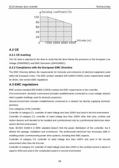
EC20 elevator door controller Technical data
68
A.2 CE
A.2.1 CE marking
The CE mark is attached to the drive to verify that the drive follows the provisions of the European Low
Voltage (2006/95/EC) and EMC Directives (2004/108/EC).
A.2.2 Compliance with the European EMC Directive
The EMC Directive defines the requirements for immunity and emissions of electrical equipment used
within the European Union. The EMC product standard (EN 61800-3:2004) covers requirements stated
for drives. See section EMC regulations
A.3 EMC regulations
EMC product standard (EN 61800-3:2004) contains the EMC requirements to the controller.
First environment: domestic environment (includes establishments connected to a low-voltage network
which supplies buildings used for domestic purposes).
Second environment includes establishments connected to a network not directly supplying domestic
premises.
Four categories of the controller:
Controller of category C1: controller of rated voltage less than 1000V and used in the first environment.
Controller of category C2: controller of rated voltage less than 1000V other than pins, sockets and
motion devices and intended to be installed and commissioned only by a professional electrician when
used in the first environment.
Note: IEC/EN 61800-3 in EMC standard doesn’t limit the power distribution of the controller, but it
defines the upstage, installation and commission. The professional electrician has necessary skills in
installing and/or commissioning power drive systems, including their EMC aspects.
Controller of category C3: controller of rated voltage less than 1000V and used in the second
environment other than the first one
Controller of category C4: controller of rated voltage more than 1000V or the nominal current is above or
equal to 400A and used in the complicated system in second environment
EC20 elevator door controller Technical data
69
A.3.1 Category C2
The emission limits are complied with the following provisions:
1. The optional EMC filter is selected according to the options and installed as specified in the EMC filter
manual.
2. The motor and control cables are selected as specified in this manual.
3. The drive is installed according to the instructions given in this manual.
In a domestic environment, this product may cause radio inference, in which
case supplementary mitigation measures may be required.
A.3.2 Category C3
The immunity performance of the drive complies with the demands of IEC/EN 61800-3, second
environment.
The emission limits are complied with the following provisions:
1. The optional EMC filter is selected according to the options and installed as specified in the EMC filter
manual.
2. The motor and control cables are selected as specified in this manual.
3. The drive is installed according to the instructions given in this manual.
A drive of category C3 is not intended to be used on a low-voltage public
network which supplies domestic premises. Radio frequency interference is
expected if the drive is used on such a network.
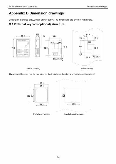
EC20 elevator door controller Dimension drawings
70
Appendix B Dimension drawings
Dimension drawings of EC20 are shown below. The dimensions are given in millimeters.
B.1 External keypad (optional) structure
Overall drawing Hole drawing The external keypad can be mounted on the installation bracket and the bracket is optional.
Installation bracket Installation dimension

EC20 elevator door controller Dimension drawings
71
B.2 Controller chart
Wall mounting (unit: mm)
Model W1 W2 H1 H2 D1 D2 Installation
hole(d)
EC20-0R4G-S2 80.0 60.0 160.0 150.0 123.5 120.3 5
EC20-0R7G-S2 80.0 60.0 160.0 150.0 123.5 120.3 5
Rail mounting (unit: mm)
Model W1 H1 H3 H4 D1 D2 Installation
hole(d)
EC20-0R4G-S2 80.0 160.0 35.4 36.6 123.5 120.3 5
EC20-0R7G-S2 80.0 160.0 35.4 36.6 123.5 120.3 5
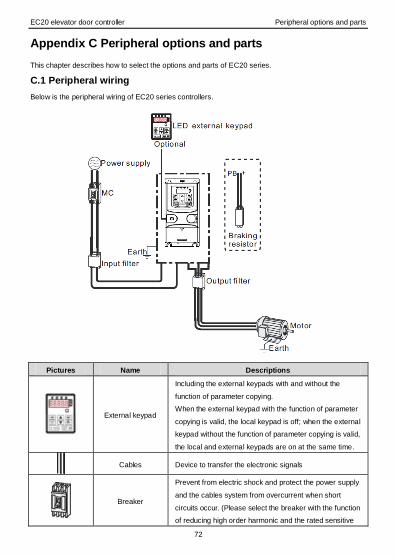
EC20 elevator door controller Peripheral options and parts
72
Appendix C Peripheral options and parts
This chapter describes how to select the options and parts of EC20 series.
C.1 Peripheral wiring
Below is the peripheral wiring of EC20 series controllers.
Pictures Name Descriptions
External keypad
Including the external keypads with and without the
function of parameter copying.
When the external keypad with the function of parameter
copying is valid, the local keypad is off; when the external
keypad without the function of parameter copying is valid,
the local and external keypads are on at the same time.
Cables Device to transfer the electronic signals
Breaker
Prevent from electric shock and protect the power supply
and the cables system from overcurrent when short
circuits occur. (Please select the breaker with the function
of reducing high order harmonic and the rated sensitive
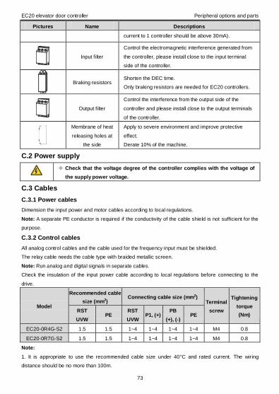
EC20 elevator door controller Peripheral options and parts
73
Pictures Name Descriptions
current to 1 controller should be above 30mA).
Input filter
Control the electromagnetic interference generated from
the controller, please install close to the input terminal
side of the controller.
Braking resistors Shorten the DEC time.
Only braking resistors are needed for EC20 controllers.
Output filter
Control the interference from the output side of the
controller and please install close to the output terminals
of the controller.
Membrane of heat
releasing holes at
the side
Apply to severe environment and improve protective
effect.
Derate 10% of the machine.
C.2 Power supply
Check that the voltage degree of the controller complies with the voltage of
the supply power voltage.
C.3 Cables
C.3.1 Power cables
Dimension the input power and motor cables according to local regulations.
Note: A separate PE conductor is required if the conductivity of the cable shield is not sufficient for the
purpose.
C.3.2 Control cables
All analog control cables and the cable used for the frequency input must be shielded.
The relay cable needs the cable type with braided metallic screen.
Note: Run analog and digital signals in separate cables.
Check the insulation of the input power cable according to local regulations before connecting to the
drive.
Model
Recommended cable
size (mm2) Connecting cable size (mm2)
Terminal
screw
Tightening
torque
(Nm) RST
UVW PE
RST
UVW P1, (+)
PB
(+), (-) PE
EC20-0R4G-S2 1.5 1.5 1~4 1~4 1~4 1~4 M4 0.8
EC20-0R7G-S2 1.5 1.5 1~4 1~4 1~4 1~4 M4 0.8
Note:
1. It is appropriate to use the recommended cable size under 40°C and rated current. The wiring
distance should be no more than 100m.
EC20 elevator door controller Peripheral options and parts
74
2. Terminals (+) and PB connects the braking resistors.
3. Where control cables must cross power cables make sure that they are arranged at an angle as near
to 90 degrees as possible.
4. Moisture inside the motor casing will reduce the insulation resistance. If moisture is suspected, dry the
motor and repeat the measurement.
C.4 Breaker and electromagnetic contactor
It is necessary to add fuse for the avoidance of overload.
It is appropriate to use a breaker (MCCB) which complies with the controller power in the 3-phase AC
power and input power and terminals. The capacity of the controller should be 1.5-2 times of the rated
current.
Due to the inherent operating principle and construction of circuit breakers,
independent of the manufacturer, hot ionized gases may escape from the
breaker enclosure in case of a short-circuit. To ensure safe use, special
attention must be paid to the installation and placement of the breakers.
Follow the manufacturer’s instructions.
It is necessary to install the electromagnetic contactor in the input side to control the switching on and off
safety of the main circuit. It can switch off the input power supply when system faults.
Model Fuse (A) Breaker (A) The rated working current of
the contactor (A)
EC20-0R4G-S2 16 16 10
EC20-0R7G-S2 16 16 16
C.6 Filters
C.6.1 C3 Filter type instruction
C3 filers are optional for EC20 series controllers.
The input interference filter can decrease the interference of the controller to the surrounding
equipments.
Output interference filter can decrease the radio noise cause by the cables between the controller and
the motor and the leakage current of the conducting wires.
Our company configured some filters for the convenient of the users.
Model Input filter
EC20-0R4G-S2 FLT-PS2003L-C-G
EC20-0R7G-S2
Note:
1. The input EMI meet the requirement of C3 after adding input filters.
2. Above options are external, the customer should indicate when purchasing.

EC20 elevator door controller Peripheral options and parts
75
C.6.2 C2 Filter type instruction
Model Input filter Output filter
EC20-0R4G-S2 FLT-PS2010H-B FLT-L02010H-B
EC20-0R7G-S2 FLT-PS2010H-B FLT-L02010H-B
Note:
1. The input EMI meet the requirement of C2 after adding input filters.
2. Above options are external, the customer should indicate when purchasing.
C.7 Braking components
C.7.1 Select the braking components
It is appropriate to use braking resistor or braking unit when the motor brakes sharply or the motor is
driven by a high inertia load. The motor will become a generator if its actual rotating speed is higher than
the corresponding speed of the reference frequency. As a result, the inertial energy of the motor and
load return to the controller to charge the capacitors in the main DC circuit. When the voltage increases
to the limit, damage may occur to the controller. It is necessary to apply braking unit/resistor to avoid this
accident happens.
Only qualified electricians are allowed to design, install, commission and
operate on the controller.
Follow the instructions in “warning” during working. Physical injury or death
or serious property may occur.
Only qualified electricians are allowed to wire. Damage to the controller or
braking options and part may occur.
Read carefully the instructions of braking resistors or units before
connecting them with the controller.
Do not connect the braking resistor with other terminals except for PB and
(+). Damage to the controller or braking circuit or fire may occur.
Connect the braking resistor or braking unit with the controller according to
the diagram. Incorrect wiring may cause damage to the controller or other
devices.
EC20 series controllers have internal braking units.
Model Type of
braking unit
Braking
resistor at
100% of the
braking
torque (Ω)
The consumed power of the braking
resistor Min.
braking
resistor
(Ω)) 10% braking 50% braking 80% braking
EC20-0R4G-S2 Internal
braking
unit
361 0.06 0.30 0.48 42
EC20-0R7G-S2 192 0.11 0.56 0.90 42
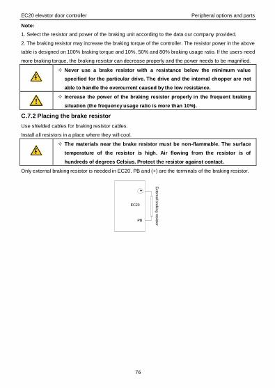
EC20 elevator door controller Peripheral options and parts
76
Note:
1. Select the resistor and power of the braking unit according to the data our company provided.
2. The braking resistor may increase the braking torque of the controller. The resistor power in the above
table is designed on 100% braking torque and 10%, 50% and 80% braking usage ratio. If the users need
more braking torque, the braking resistor can decrease properly and the power needs to be magnified.
Never use a brake resistor with a resistance below the minimum value
specified for the particular drive. The drive and the internal chopper are not
able to handle the overcurrent caused by the low resistance.
Increase the power of the braking resistor properly in the frequent braking
situation (the frequency usage ratio is more than 10%).
C.7.2 Placing the brake resistor
Use shielded cables for braking resistor cables.
Install all resistors in a place where they will cool.
The materials near the brake resistor must be non-flammable. The surface
temperature of the resistor is high. Air flowing from the resistor is of
hundreds of degrees Celsius. Protect the resistor against contact.
Only external braking resistor is needed in EC20. PB and (+) are the terminals of the braking resistor.
+
PB
Exte
rna
l bra
kin
g re
sis
tor
EC20

EC20 elevator door controller Further information
77
Appendix D Further information
D.1 Product and service inquiries
Address any inquiries about the product to your local INVT offices, quoting the type designation and
serial number of the unit in question. A listing of INVT sales, support and service contacts can be found
by navigating to www.invt.com.cn.
D.2 Feedback of INVT controllers manuals
Your comments on our manuals are welcome. Go to www.invt.com.cn and select Online Feedback of
Contact Us.
D.3 Document library on the internet
You can find manuals and other product documents in PDF format on the Internet. Go to
www.invt.com.cn and select Service and Support of Document Download.
201609(V1.0)
6 6 0 0 7 - 0 0 0 9 3


![[Machine Learning] Kỹ thuật SVM](https://img.pdfslide.us/doc/110x75/55cf9905550346d0339b135d/machine-learning-ky-thuat-svm.jpg)