Embed Size (px)
Citation preview

402.344.4434 • www.brand-hyd.com
ISO 9001:2008 WITH DESIGNCertificate #02.002.1
APPLICATION:Proportionally control the speed and direction of hydraulic motors and cylinders. This low cost unit can be configured in multiple ways to cover many applications.
EC - SeriesElectronic Control Box
Engineering & Manufacturing Solutions
REV(D)
A-116
EC Electronic Control Box
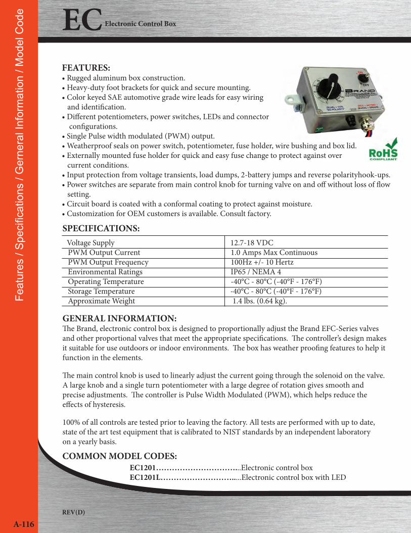
Voltage Supply 12.7-18 VDC PWM Output Current 1.0 Amps Max Continuous PWM Output Frequency 100Hz +/- 10 Hertz Environmental Ratings IP65 / NEMA 4 Operating Temperature -40°C - 80°C (-40°F - 176°F) Storage Temperature -40°C - 80°C (-40°F - 176°F) Approximate Weight 1.4 lbs. (0.64 kg).
SPECIFICATIONS:
FEATURES:• Rugged aluminum box construction.• Heavy-duty foot brackets for quick and secure mounting.• Color keyed SAE automotive grade wire leads for easy wiring and identification.• Different potentiometers, power switches, LEDs and connector configurations.• Single Pulse width modulated (PWM) output.• Weatherproof seals on power switch, potentiometer, fuse holder, wire bushing and box lid.• Externally mounted fuse holder for quick and easy fuse change to protect against over current conditions.• Input protection from voltage transients, load dumps, 2-battery jumps and reverse polarityhook-ups.• Power switches are separate from main control knob for turning valve on and off without loss of flow setting.• Circuit board is coated with a conformal coating to protect against moisture.• Customization for OEM customers is available. Consult factory.
Feat
ures
/ Sp
ecifi
catio
ns /
Ger
nera
l Inf
orm
atio
n / M
odel
Cod
e
GENERAL INFORMATION:The Brand, electronic control box is designed to proportionally adjust the Brand EFC-Series valves and other proportional valves that meet the appropriate specifications. The controller’s design makes it suitable for use outdoors or indoor environments. The box has weather proofing features to help it function in the elements.
The main control knob is used to linearly adjust the current going through the solenoid on the valve. A large knob and a single turn potentiometer with a large degree of rotation gives smooth and precise adjustments. The controller is Pulse Width Modulated (PWM), which helps reduce the effects of hysteresis.
100% of all controls are tested prior to leaving the factory. All tests are performed with up to date,state of the art test equipment that is calibrated to NIST standards by an independent laboratoryon a yearly basis.
COMMON MODEL CODES:EC1201…………………………...Electronic control boxEC1201L……………………….....Electronic control box with LED

402.344.4434 • www.brand-hyd.com
A-117
Model C
odes
() indicate momentary function
CREATING A MODEL CODE:
Wire/Cable Bushing Location #1 Mandatory Selection (See Figure 6 & 8) continued:2E - 2 Wires - Multi Conductor Cable 2-Way Deutsch DT Series, Plug, Female Terminals
2G - 2 Wires - Multi Conductor Cable 2-Way Molex ML-XT Series, Plug, Female Terminals
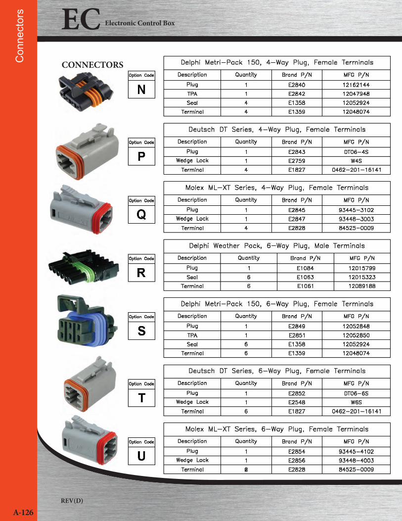
3M - 4 Wires - Flying leads 4-Way Weather Pack, Plug, Female Terminals
3N - 4 Wires - Flying leads 4-Way Metri-Pack 150 Series, Plug, Female Terminals
3P - 4 Wires - Flying leads 4-Way Deutsch DT Series, Plug, Female Terminals
3Q - 4 Wires - Flying leads 4-Way Molex ML-XT Series, Plug, Female Terminals
4M - 4 Wires - Multi Conductor Cable 4-Way Weather Pack, Plug, Female Terminals
4N - 4 Wires - Multi Conductor Cable 4-Way Metri-Pack 150 Series, Plug, Female Terminals
4P - 4 Wires - Multi Conductor Cable 4-Way Deutsch DT Series, Plug, Female Terminals
4Q - 4 Wires - Multi Conductor Cable 4-Way Molex ML-XT Series, Plug, Female Terminals
5R - 6 Wires - Flying leads 6-Way Weather Pack, Plug, Female Terminals
5S - 6 Wires - Flying leads 6-Way Metri-Pack 150 Series, Plug, Female Terminals
5T - 6 Wires - Flying leads 6-Way Deutsch DT Series, Plug, Female Terminals
5U - 6 Wires - Flying leads 6-Way Molex ML-XT Series, Plug, Female Terminals
6R - 6 Wires - Multi Conductor Cable 6-Way Weather Pack, Plug, Female Terminals
6S - 6 Wires - Multi Conductor 6-Way Metri-Pack 150 Series, Plug, Female Terminals
6T - 6 Wires - Multi Conductor Cable 6-Way Deutsch DT Series, Plug, Female Terminals
6U - 6 Wires - Multi Conductor Cable 6-Way Molex ML-XT Series, Plug, Female Terminals
POTENTIOMETER:01 - Single Turn - 312° roation (See Figure 1)03 - 3 Turn - 1080° roation (See Figure 2)05 - 5 Turn - 1800° roation (See Figure 3)07 - 10 Turn - 3600° roation (See Figure 4)
LED INDICATOR (See Figure 5) :L - Red LED (Single, when SPST switch is selected)
M - Green LED (Single, when SPST switch is selected)
N - Red LED (Top & Bottom, when DPDT switch is
selected)
P - Green LED (Top & Bottom, when DPDT switch is
selected)
Q - Red LED (Top) / Green LED (Bottom), when DPDT
switch is selected)
R - Green LED (Top) / Red LED (Bottom), when DPDT
switch is selected)
POWER SWITCH:Omit – ON-NONE-OFF (SPST)
1 - (ON)-NONE-OFF (SPST)
2 - ON-OFF-ON (DPDT)
3 - (ON)-OFF-(ON) (DPDT)
4 - (ON)-OFF-ON (DPDT)
5 - ON-OFF-(ON) (DPDT)
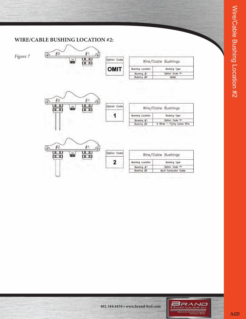
Optional Power Bushing Location #2 (See Figure 7):Omit - No Bushing
1 - Flying leads
2 - Multiconductor cable
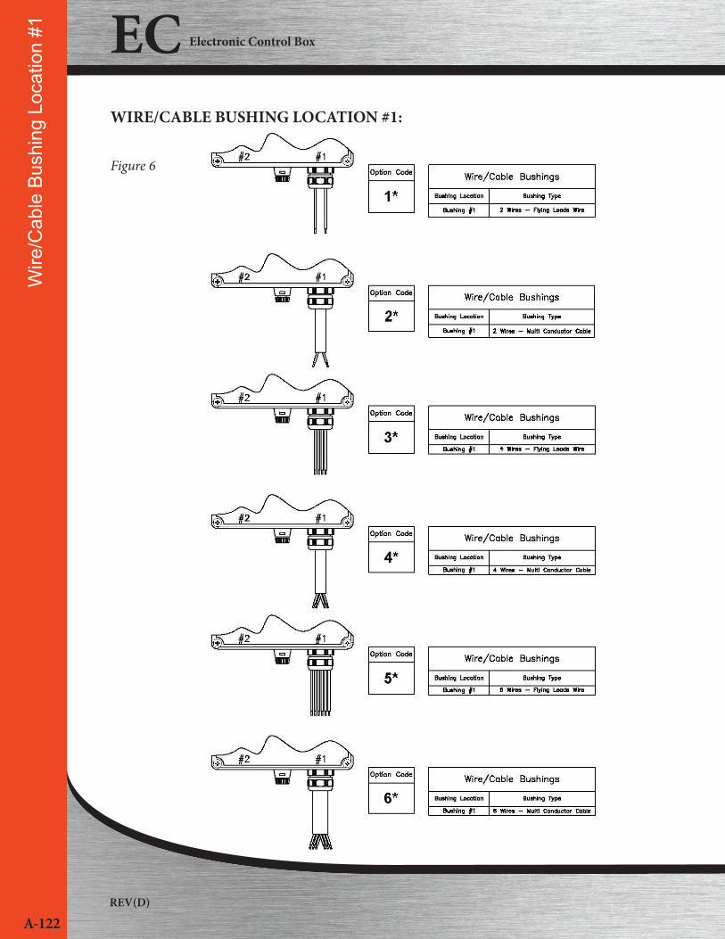
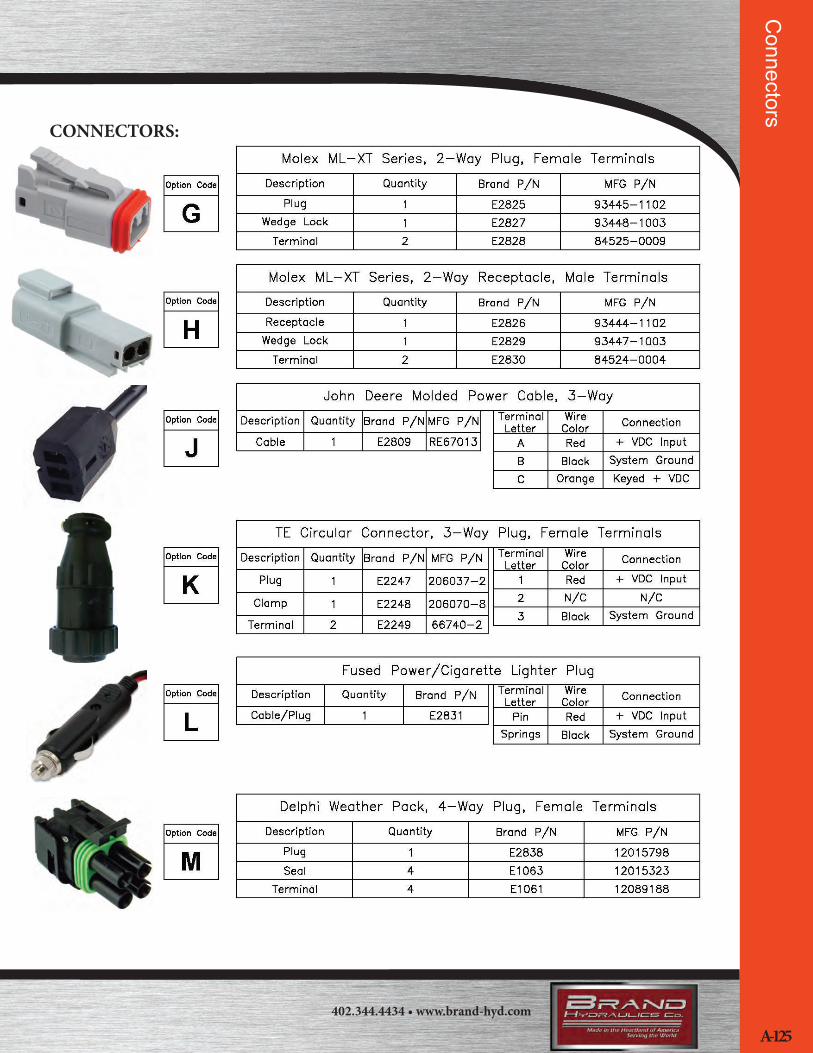
Wire/Cable Bushing Location #1 Mandatory Selection (See Figure 6 & 8):1A - 2 Wires - Flying leads 2-Way Weather Pack, Plug, Female Terminals
1C - 2 Wires - Flying leads 2-Way Metri-Pack 150 Series, Plug, Female
Terminals
1E - 2 Wires - Flying leads 2-Way Deutsch DT Series, Plug, Female
Terminals
1G - 2 Wires - Flying leads 2-Way Molex ML-XT Series, Plug, Female
Terminals
2A - 2 Wires - Multi Conductor Cable 2-Way Weather Pack, Plug, Female
Terminals
2C - 2 Wires - Multi Conductor Cable 2-Way Metri-Pack 150 Series,
Plug, Female Terminals
Connector for Optional Power BushingIf Power Bushing is selected an option code must be selected Location #2 (See Figure 8) :OMIT - No Connector or Optional Power Bushing was not selected
B - 2-Way Weather Pack, Receptacle, Male Terminals
D - 2-Way Metri-Pack 150 Series, Receptacle, Male Terminals
F - 2-Way Deutsch DT Series, Receptacle, Male Terminals
H - 2-Way Molex ML-XT Series, Receptacle, Male Terminals
J - 3-Way John Deere Power Connector Must use bushing location #1
Multiconductor (Option 2)
K - 3-Way AMP CPC Circular Power Connector Must use
bushing location #1 Multiconductor (Option 2)
L - Fused Power/Cigarette Lighter Plug Must use bushing location #1
flying leads (Option 1)
SERIES:ECOPERATING VOLTAGE:12 - 12VDC

REV(D)
A-118
EC Electronic Control Box
CREATING A MODEL CODE INFORMATION:LED INDICATOR:• If 2 LEDs are selected you must select a DPDT power switch
Mod
el C
odes
/ Pa
rts L
ist /
Acc
esso
ries
PARTS LIST:E1028……………………………....Surface mount PCB standoffE1034……………………………....Mounting foot hex nutE1049……………………………....Panel mount fuse holderE1050……………………………....Knob, BlackE1071……………………………....Potentiometer shaft sealE1466…………………………...… Power switch, DPDT, ON-OFF-ON, screw terminalsE1467…………………………...… Power switch, DPDT, (ON)-OFF-(ON), screw terminalsE1726……………………………....Fuse 1.5 ampE1747…………………………...… Power switch, SPST, ON-NONE-OFF, screw terminalsE1758……………………………....Switch boot sealE1803.......……………………….....Single Turn Long Life Potentiometer, 10K w/6” LeadsE1953……………………………....Mounting foot lock washerE2170……………………………....LED, Panel Mount, RedE2563……………………………....3 Long Life Potentiometer, 10K w/6” LeadsE2833…………………………........Power switch, SPST, (ON)-NONE-OFF, screw terminalsE2834…………………………...….Power switch, DPDT, ON-OFF-(ON), screw terminalsE2835……………………………....LED, Panel Mount, GreenE2836……………………………....5 Long Life Potentiometer, 10K w/6” LeadsE2837……………………………....10 Long Life Potentiometer, 10K w/6” LeadsP1158……………………………....Mounting foot bracket
ACCESSORIES LIST:E2815...............................................120VAC Wall-mount power supply with 6 ft. c rd. Flying leads w/loose Quick Disconnect TerminalsE2816...............................................120VAC Wall-mount power supply with 6 ft. c rd. Weather Pack, 2-Way, Plug, Female TerminalsE2817...............................................120VAC Wall-mount power supply with 6 ft. c rd. Metri-Pack 150 Series, 2-Way, Plug, Female TerminalsE2818...............................................120VAC Wall-mount power supply with 6 ft. c rd. Deutsch DT Series, 2-Way, Plug, Female TerminalsE2819...............................................120VAC Wall-mount power supply with 6 ft. c rd. Molex ML-XT Series, 2-Way, Plug, Female Terminals
WIRE/CABLE BUSHINGS:• Wire/Cable bushing location #1 is a mandatory selection• Wire/Cable power bushing location #2 is optional• Flying leads and multi conductor cables are 18” long
Note: ( ) indicate momentary function

402.344.4434 • www.brand-hyd.com
A-119
Output C
urvesEC1201 SERIES CURRENT VS. DIAL PLATE:
Figure 1
EC1203 SERIES CURRENT VS. DEGREES OF ROTATION:
Figure 2
REV(D)
A-120
EC Electronic Control BoxO
utpu
t Cur
ves
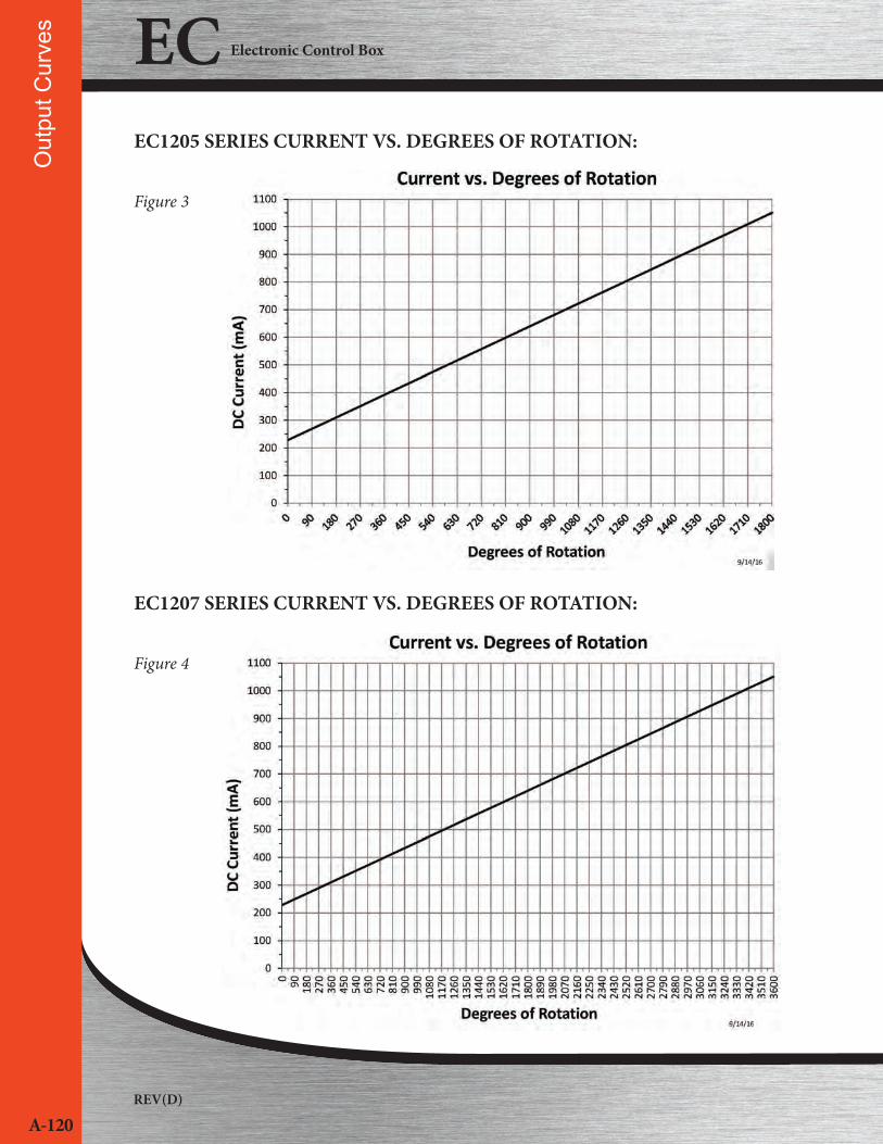
EC1205 SERIES CURRENT VS. DEGREES OF ROTATION:
Figure 3
EC1207 SERIES CURRENT VS. DEGREES OF ROTATION:
Figure 4

402.344.4434 • www.brand-hyd.com
A-121
Front Cover Layout
KNOB, SWITCH AND LED LAYOUTS:
Figure 5
EC1203EC1205EC1207
EC1203LEC1205LEC1207L
EC1203N2EC1205N2EC1207N2
EC1201
EC1201L
EC1201N2
REV(D)
A-122
EC Electronic Control BoxW
ire/C
able
Bus
hing
Loc
atio
n #1
WIRE/CABLE BUSHING LOCATION #1:
Figure 6
402.344.4434 • www.brand-hyd.com
A-123
Wire/C
able Bushing Location #2
WIRE/CABLE BUSHING LOCATION #2:
Figure 7

REV(D)
A-124
EC Electronic Control BoxC
onne
ctor
s
CONNECTORS: Figure 8
402.344.4434 • www.brand-hyd.com
A-125
Connectors
CONNECTORS:
REV(D)
A-126
EC Electronic Control BoxC
onne
ctor
s
CONNECTORS:

402.344.4434 • www.brand-hyd.com
A-127
DIMENSIONAL DATA: inches & [millimeters]
Dim
ensional DataEC1201, EC1203, EC1205, EC1207 SERIES EC1201 SERIES SHOWN
REV(D)
A-128
EC Electronic Control BoxW
iring
Dia
gram
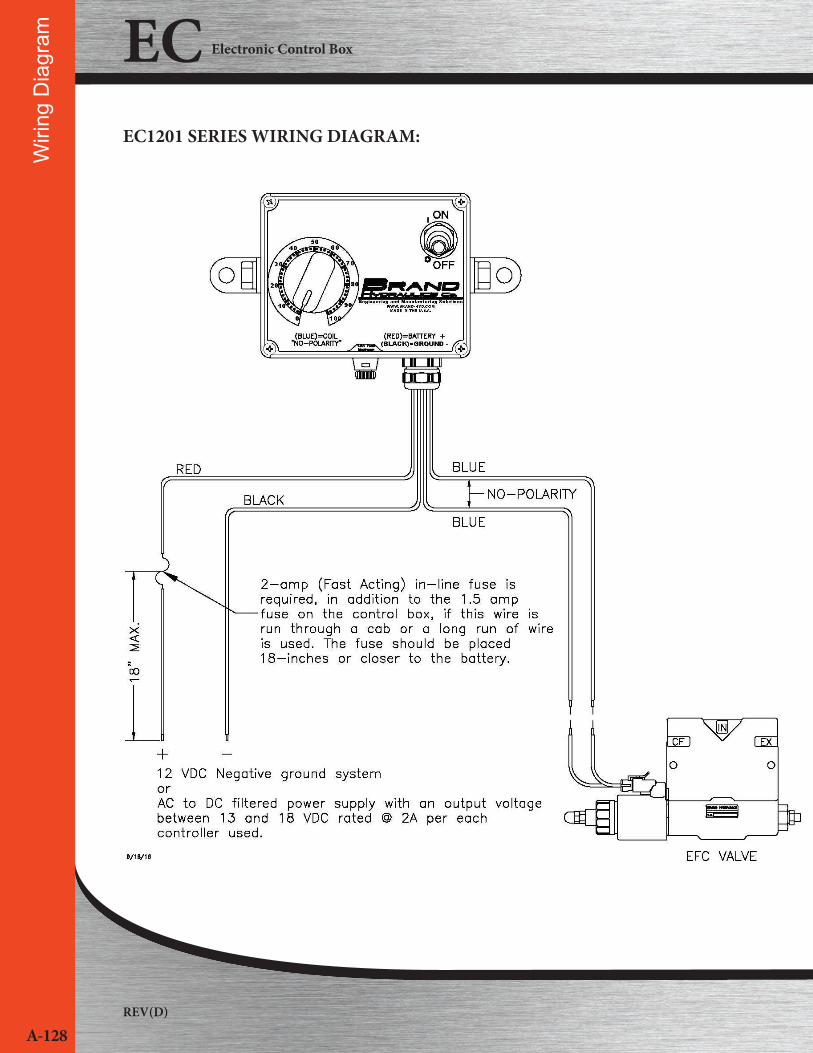
EC1201 SERIES WIRING DIAGRAM:

402.344.4434 • www.brand-hyd.com
A-129
Wiring D
iagramEC1201N2 SERIES WIRING DIAGRAM:
It is the purchaser’s responsibility to determine the suitability of any Brand Hydraulics product for an intended application, and to insure that it is installed in accordance with all federal, state, local, private safety, health regulations, and codes and standards. Due to the unlimited variety of machines, vehicles, and equip-ment on which our products can be used, it is impossible for Brand Hydraulics to offer expert advice on the suitability of a product for a specific application. We believe that it is our customer’s responsibility to undertake the appropriate testing and evaluation to prevent injury to the end user.
All product, product specifications and data are subject to change without notice to improve reliability, function or design or otherwise.