Embed Size (px)
Citation preview
1
EC 6801- WIRELESS COMMUNICATION
UNIT I WIRELESS CHANNELS
PART-A
1. What is meant by small and large scale fading? (June 2013)
The rapid fluctuations of the amplitudes, phases; or multipath delays of a radio signal
over a short period of time or travel distance is known as small scale fading.
The rapid fluctuations of the amplitudes, phases, or multipath delays of a radio signal over
a long period of time or travel distance is known as large scale fading.
2. What are the basic requirements for wireless services?(May 2014)
Wireless communication is a process of transmitting & receiving voice and data using
electro-magnetic waves in free space. They are not physically connected. It is a Serial
communication
3. State the propagation effects in mobile radio. (May 2014)
When wavelength is less than the obstacle size, the in there is a chance of
Blocking, Reflection, Refraction
4. Interpret link budget equation. (May 2014)
In designing a system for reliable communications, it must to perform a link budge
calculation to ensure that sufficient power is available at the receiver to close the link and
to meet the SNR requirement. The basis for the link budget is the friis equation
5. List the different types of propagation mechanisms.(Dec 2014)
Multipath propagation often lengthens the time required for the baseband portion of the
signal to reach the receiver which can cause signal smearing due to inter-symbol
interference.
6. What are Rayleigh and Ricean fading? (June 2014)
Used to describe the statistical time varying nature of the received envelope of a flat
fading signal OR the envelope of an individual multipath component Sum of 2 quadrature
Gaussian noise signals obey Releigh distribution.
2
7. What are the different modules of a basic cellular system? (Dec 2014)
It consist of Wireless wide-area networks (WWAN)
Wireless local area networks (WLAN)
Wireless personal area networks (WP AN
8. What are the different fading effects due to Doppler spread?(Dec 2014)(Dec 2013)
Depends on QOW fast the baseband signal changes compared to the rate of change of the
channel. Not due to propagation loss!!
9. State the difference between small-scale fading and large scale fading. (May
2015)(June 2013)
The rapid fluctuations of the amplitudes, phases; or multipath delays of a radio
signal over a short period of time or travel distance is known as small scale fading.
The rapid fluctuations of the amplitudes, phases, or multipath delays of a radio signal over
a long period of time or travel distance is known as large scale fading.
10. Interpret snell's law. (May 2015) (June 2013)
It is a formula used to describe the relationship between the angles of incidence and
refraction, when referring to light or other waves passing through a boundary between
two different isotropic media.
11. Define coherence time & coherence Bandwidth. (dec 2015)(May/June 2016)
Coherence time Tc is used to characterize the time varying nature of the frequency
depressiveness of the channel in the domain
Tc =1/fm Doppler spread and coherence time are inversely proportional
Coherence Bandwidth Bc is a statistical measure of the range of frequencies over which
two frequency components have a strong potential for amplitude correlation.
12. What is fading and Doppler spread. (May/June 2016)
Fading takes place in mobile signal propagation due to multi path time delay
spread.Doppler spread is denoted as BD and it is defined as a set of frequencies over
which the Doppler spread at the receiver end is non zero value.For example if a pure
sinusoidal tone of frequencyis transmitted and is denoted as fc and the received signal
3
spectrum is called Doppler spectrum consisting of components in the range from fc-fd to
fc+fd, in which fd refers to Doppler shift in frequency .
Part B
1. Discuss about technical challenges faced by the wireless communication. (June 2014)
Technical Challenges:
Multipath Propagation
For wireless communications, the transmission medium is the radio channel between
transmitter TX and receiver RX. The signal can get from the TX to the RX via a number of
different propagation paths. In some cases, a Line Of Sight (LOS) connection might exist
between TX and RX. Furthermore, the signal can get from the TX to the RX by being
reflected at or diffracted by different Interacting Objects (IOs) in the environment: houses,
mountains (for outdoor environments), windows, walls, etc. The number of these possible
propagation paths is very large. Each of the paths has a distinct amplitude, delay (runtime of
the signal), direction of departure from the TX, and direction of arrival; most importantly, the
components have different phase shifts with respect to each other. In the following, we
discuss some implications of the multipath propagation for system design.
Fading:
A simple RX cannot distinguish between the different Multi Path Components (MPCs); it
just adds them up, so that they interfere with each other. The interference between them can
be constructive or destructive, depending on the phases of the MPCs. The phases, in turn,
depend mostly on the run length of the MPC, and thus on the position of the Mobile Station
(MS) and the IOs. For this reason, the interference, and thus the amplitude of the total signal,
changes with time if TX, RX, or IOs is moving. This effect – namely, the changing of the
total signal amplitude due to interference of the different MPCs – is called small-scale fading.
Obstacles can lead to a shadowing of one or several MPCs. Imagine, e.g., the MS at first (at
position A) has LOS to the Base Station (BS). As the MS moves behind the high-rise building
(at position B), the amplitude of the component that propagates along the direct connection
(LOS) between BS and MS greatly decreases. This is due to the fact that the MS is now in the
4
radio shadow of the high-rise building, and any wave going through or around that building is
greatly attenuated – an effect called shadowing. The MS has to move over large distances
(from a few meters up to several hundreds of meters) to move from the light to the dark zone.
For this reason, shadowing gives rise to large-scale fading.
Inter symbol Interference
The runtimes for different MPCs are different. We have already mentioned above that
this can lead to different phases of MPCs, which lead to interference in narrowband systems.
In a system with large bandwidth, and thus good resolution in the time domain,3 the major
consequence is signal dispersion: in other words, the impulse response of the channel is not a
single delta pulse but rather a sequence of pulses (corresponding to different MPCs), each of
which has a distinct arrival time in addition to having a different amplitude and phase. This
signal dispersion leads to InterSymbol Interference (ISI) at the RX.
Spectrum Limitations
The spectrum available for wireless communications services is limited, and
regulated by international agreements. For this reason, the spectrum has to be used in a highly
efficient manner. Two approaches are used: regulated spectrum usage, where a single
network operator has control over the usage of the spectrum, and unregulated spectrum,
where each user can transmit without additional control, as long as (s)he complies with
certain restrictions on the emission power and bandwidth. In the following, we first review
the frequency ranges assigned to different communications services. We then discuss the
basic principle of frequency reuse for both regulated and unregulated access
Assigned Frequencies
The frequency assignment for different wireless services is regulated by the
International Telecommunications Union (ITU), a suborganization of the United Nations. In
its tri-annual conferences (World Radio Conferences), it establishes worldwide guidelines for
the usage of spectrum in different regions and countries. Further regulations are issued by the
frequency regulators of individual countries, including the Federal Communications
5
Commission (FCC) in the U.S.A., the Association of Radio Industries and Businesses (ARIB)
in Japan, and the European Conference of Postal and Telecommunications Administrations
(CEPT) in Europe.
While the exact frequency assignments differ, similar services tend to use the same frequency
ranges all over the world:
• Below 100 MHz: at these frequencies, we find Citizens’ Band (CB) radio, pagers, and
analog cordless phones.
• 100–800 MHz: these frequencies are mainly used for broadcast (radio and TV) applications.
• 400–500 MHz: a number of cellular and trunking radio systems make use of this band. It is
mostly systems that need good coverage, but show low user density.
• 800–1000 MHz: several cellular systems use this band (analog systems as well as
secondgenerationcellular). Also some emergency communications systems (trunking radio)
make use of this band.
• 1.8–2.1 GHz: this is the main frequency band for cellular communications. The current
(secondgeneration) cellular systems operate in this band, as do most of the third-generation
systems. Many cordless systems also operate in this band.
• 2.4–2.5 GHz: the Industrial, Scientific, and Medical (ISM) band. Cordless phones, Wireless
Local Area Networks (WLANs) and wireless Personal Area Networks (PANs) operate in this
band; they share it with many other devices, including microwave ovens.
• 3.3–3.8 GHz: is envisioned for fixed wireless access systems.
• 4.8–5.8 GHz: in this range, most WLANs can be found. Also, the frequency range between
5.7 and 5.8 GHz can be used for fixed wireless access, complementing the 3-GHz band. Also
car-to-car communications are working in this band.
• 11–15 GHz: in this range we can find the most popular satellite TV services, which use
14.0–14.5 GHz for the uplink, and 11.7–12.2 GHz for the downlink.
Frequency Reuse in Regulated Spectrum
Since spectrum is limited, the same spectrum has to be used for different wireless
connections in different locations. To simplify the discussion, let us consider in the following
a cellular system where different connections (different users) are distinguished by the
6
frequency channel (band around a certain carrier frequency) that they employ. If an area is
served by a single BS, then the available spectrum can be divided into N frequency channels
that can serve N users simultaneously. If more than N users are to be served, multiple BSs are
required, and frequency channels have to be reused in different locations. For this purpose,
we divide the area (a region, a country, or a whole continent) into a number of cells; we also
divide the available frequency channels into several groups. The channel groups are now
assigned to the cells. The important thing is that channel groups can be used in multiple cells.
The only requirement is that cells that use the same frequency group do not interfere with
each other significantly. It is fairly obvious that the same carrier frequency can be used for
different connections in, say, Rome and Stockholm, at the same time. The large distance
between the two cities makes sure that a signal from the MS in Stockholm does not reach the
BS in Rome, and can therefore not cause any interference at all. But in order to achieve high
efficiency, frequencies must actually be reused much more often – typically, several times
within each city. Consequently, intercell interference.
Frequency Reuse in Unregulated Spectrum
In contrast to regulated spectrum, several services use frequency bands that are
available to the general public. For example, some WLANs operate in the 2.45-GHz band,
which has been assigned to “ISM” services. Anybody is allowed to transmit in these bands, as
long as they (i) limit the emission power to a prescribed value, (ii) follow certain rules for the
signal shape and bandwidth, and (iii) use the band according to the (rather broadly defined)
purposes stipulated by the frequency regulators. As a consequence, a WLAN receiver can be
faced with a large amount of interference. This interference can either stem from other
WLAN transmitters or from microwave ovens, cordless phones, and other devices that
operate in the ISM band. For this reason, a WLAN link must have the capability to deal with
interference. That can be achieved by selecting a frequency band within the ISM band at
which there is little interference, by using spread spectrum techniques, or some other
appropriate technique.
7
Limited Energy
The requirement for small energy consumption results in several technical
imperatives:
• The power amplifiers in the transmitter have to have high efficiency. As power amplifiers
account for a considerable fraction of the power consumption in an MS, mainly amplifiers
with an effi- ciency above 50% should be used in MSs. Such amplifiers – specifically, class-
C or class-F amplifiers – are highly nonlinear. As a consequence, wireless communications
tend to use modulation formats that are insensitive to nonlinear distortions. For example,
constant envelope signals are preferred.
• Signal processing must be done in an energy-saving manner. This implies that the digital
logic should be implemented using power-saving semiconductor technology like
Complementary Metal Oxide Semiconductor (CMOS), while the faster but more power-
hungry approaches like Emitter Coupled Logic (ECL) do not seem suitable for MSs. This
restriction has important consequences for the algorithms that can be used for interference
suppression, combating of ISI, etc.
• The RX (especially at the BS) needs to have high sensitivity. For example, Global System
for Mobile Communications (GSM) is specified so that even a received signal power of −100
dBm leads to an acceptable transmission quality. Such an RX is several orders of magnitude
more sensitive than a TV RX. If the GSM standard had defined −80 dBm instead, then the
transmit power would have to be higher by a factor of 100 in order to achieve the same
coverage. This in turn would mean that – for identical talktime – the battery would have to be
100 times as large – i.e., 20 kg instead of the current 200 g. But the high requirements on RX
sensitivity have important consequences for the construction of the RX (low-noise amplifiers,
sophisticated signal processing to fully exploit the received signal) as well as for network
planning.
• Maximum transmit power should be used only when required. In other words, transmit
power should be adapted to the channel state, which in turn depends on the distance between
TX and RX (power control). If the MS is close to the BS, and thus the channel has only a
small attenuation, transmit power should be kept low. Furthermore, for voice transmission,
8
the MS should only transmit if the user at the MS actually talks, which is the case only about
50% of the time (Discontinuous Voice Transmission (DTX)).
• For cellular phones, and even more so for sensor networks, an energy-efficient “standby” or
“sleep” mode has to be defined.
Several of the mentioned requirements are contradictory. For example, the requirement to
build an RX with high sensitivity (and thus, sophisticated signal processing) is in contrast to
the requirement of having energy-saving (and thus slow) signal processing. Engineering
tradeoffs are thus called for.
2. (i) Explain how signal propagates against free space attenuation and reflection. (16)
(June 2014)
Free Space Propagation
For propagation distances d much larger than the square of the antenna size divided by
the wavelength, the far-field of the generated electromagnetic wave dominates all other
components (in the far-field region the electric and magnetic fields vary inversely with
distance). In free space, the power radiated by an isotropic antenna is spread uniformly and
without loss over the surface of a sphere surrounding the antenna. An isotropic antenna is a
hypothetical entity. Even the simplest antenna has some directivity. For example, a linear
dipole has uniform power flow in any plane perpendicular to the axis of the dipole
(omnidirectionality) and the maximum power flow is in the equatorial plane.
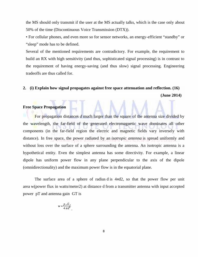
The surface area of a sphere of radius d is 4 d2, so that the power flow per unit
area w(power flux in watts/meter2) at distance d from a transmitter antenna with input accepted
power pT and antenna gain GT is
.
9
Transmitting antenna gain is defined as the ratio of the intensity (or power flux) radiated
in some particular direction to the radiation intensity that would be obtained if the power
accepted by the antenna were radiated isotropically. When the direction is not stated, the power
gain is usually taken in the direction of maximum power flow. The product GT pT is called
the effective radiated power (ERP) of the transmitter. The available power pR at the terminals
of a receiving antenna with gain GR is
where A is the effective area or aperture of the antenna and
The wavelength = c / fc with c the velocity of light and fcthe carrier frequency.
While cellular telephone operator mostly calculate in received powers, in the planning of
the coverage area of broadcast transmitters, the CCIR recommends the use of the electric field
strength E at the location of the receiver. The conversion is
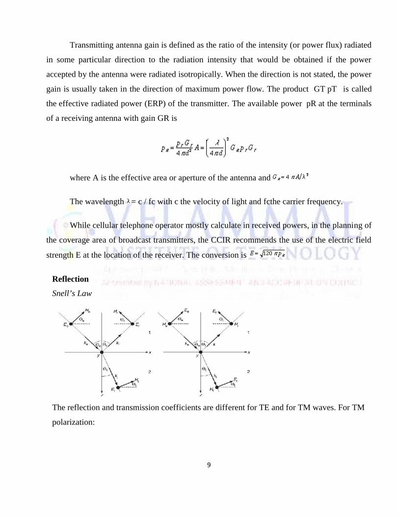
Reflection
Snell’s Law
The reflection and transmission coefficients are different for TE and for TM waves. For TM
polarization:
10
and for TE polarization:
The d−4Power Law
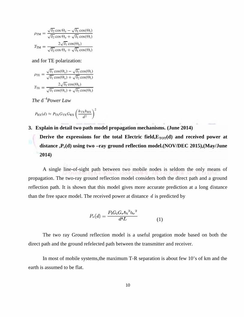
3. Explain in detail two path model propagation mechanisms. (June 2014)
Derive the expressions for the total Electric field,ETOT(d) and received power at
distance ,Pr(d) using two –ray ground reflection model.(NOV/DEC 2015),(May/June
2014)
A single line-of-sight path between two mobile nodes is seldom the only means of
propagation. The two-ray ground reflection model considers both the direct path and a ground
reflection path. It is shown that this model gives more accurate prediction at a long distance
than the free space model. The received power at distance is predicted by
(1)
The two ray Ground reflection model is a useful progation mode based on both the
direct path and the ground refelected path between the transmitter and receiver.
In most of mobile systems,the maximum T-R separation is about few 10’s of km and the
earth is assumed to be flat.
11
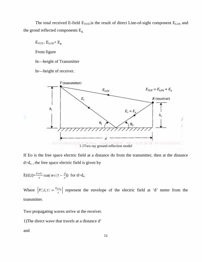
The total received E-field ETOT,is the result of direct Line-of-sight component ELOS and
the grond reflected components Eg
ETOT= ELOS+ Eg
From figure
ht—height of Transmitter
hr—height of receiver.
1.1Two ray ground reflection model
If Eo is the free space electric field at a distance do from the transmitter, then at the distance
d>do , the free space electric field is given by
E(d,t)= )) for d>do
Where represent the envelope of the electric field at ‘d’ meter from the
transmitter.
Two propagating waves arrive at the receiver.
1)The direct wave that travels at a distance d’
and
12
2)The reflected wave that travels a distance d’’
Finally,we can get the total electric field is the sum of above two components and is given by
=
Path loss:
For large values of d ,path loss is independent of frequency.It depends upon antenna heights h t
and hr
PL(dB)=40 logd-[10log Gt+10log Gr+20 loght+20 log hr]
4. i) Discuss in detail Two Ray Rayleigh Fading model (8)
ii) Describe on Rician distribution. (8) (Dec 2014)
Rayleigh fading model
Rewriting this in terms of in-phase and quadrature-phase components in real passband
notation,we obtain
A zero-mean Gaussian random variable has the pdf:
and a pdf for r – namely, a Rayleigh distribution:
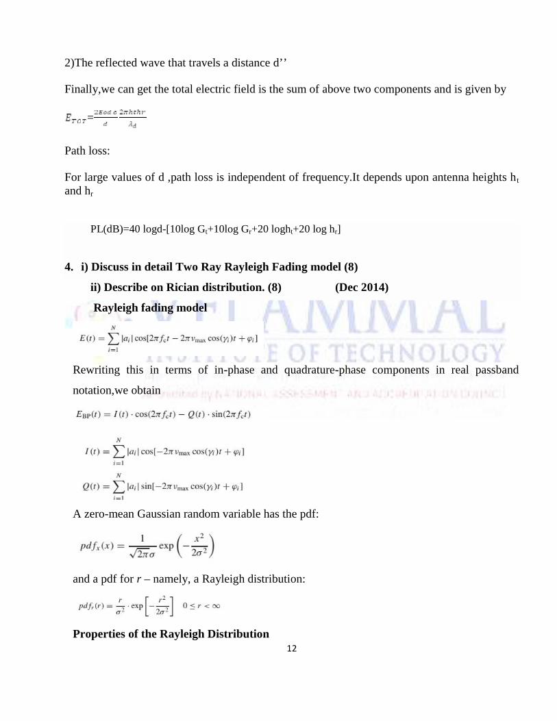
Properties of the Rayleigh Distribution
13
Pdf of a Rayleigh distribution.
Ricean Distribution
The pdf of the amplitude is given by the Rice distribution
I0(x) is the modified Bessel function of the first kind, zero order.
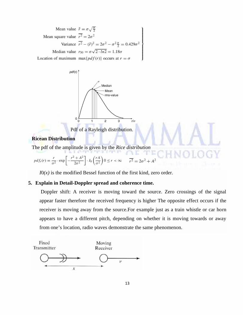
5. Explain in Detail-Doppler spread and coherence time.
Doppler shift: A receiver is moving toward the source. Zero crossings of the signal
appear faster therefore the received frequency is higher The opposite effect occurs if the
receiver is moving away from the source.For example just as a train whistle or car horn
appears to have a different pitch, depending on whether it is moving towards or away
from one’s location, radio waves demonstrate the same phenomenon.
14
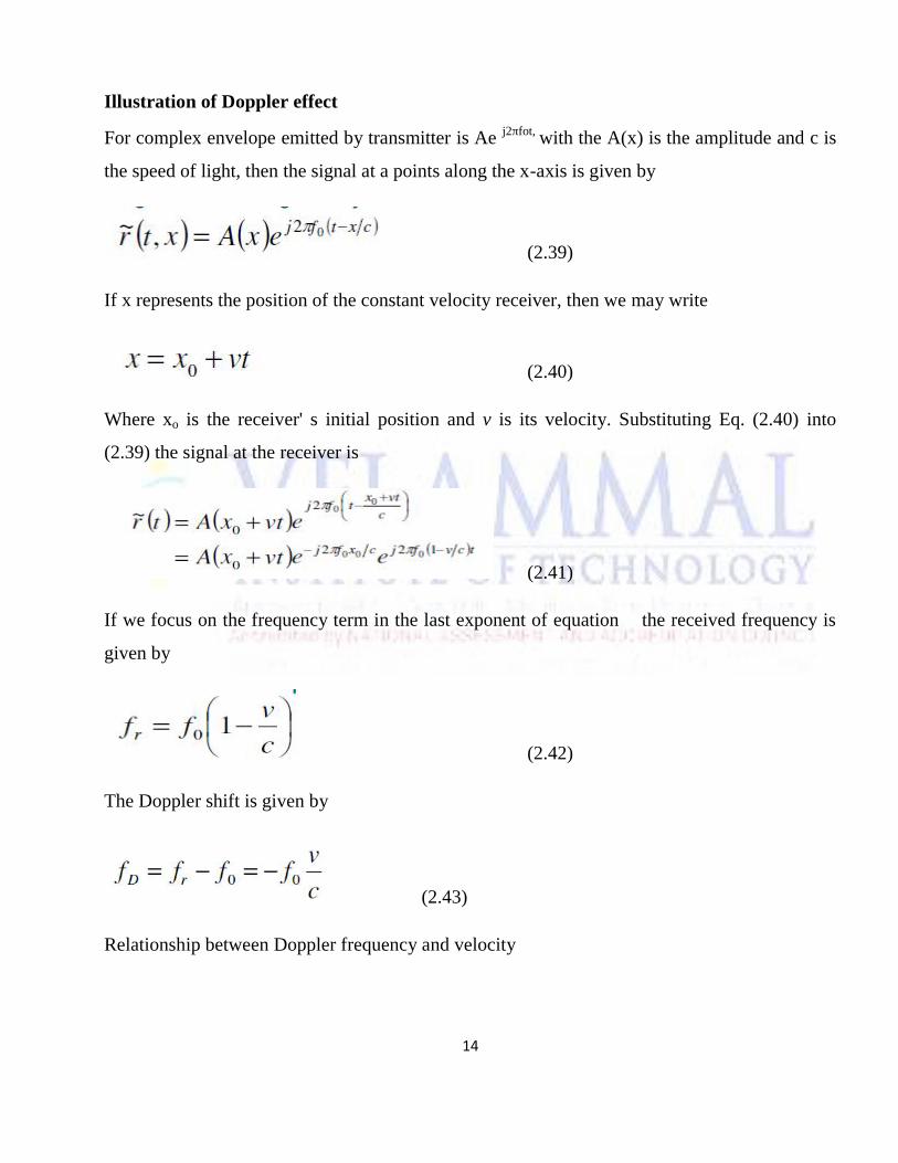
Illustration of Doppler effect
For complex envelope emitted by transmitter is Ae j2πfot, with the A(x) is the amplitude and c is
the speed of light, then the signal at a points along the x-axis is given by
(2.39)
If x represents the position of the constant velocity receiver, then we may write
(2.40)
Where xo is the receiver' s initial position and v is its velocity. Substituting Eq. (2.40) into
(2.39) the signal at the receiver is
(2.41)
If we focus on the frequency term in the last exponent of equation the received frequency is
given by
(2.42)
The Doppler shift is given by
(2.43)
Relationship between Doppler frequency and velocity
15
(2.44)
If the terminal motion and the direction of radiation are at an angle ψ, shift can be expressed as
(2.45)
For operating frequencies between 100MHz and 2GHz and for speeds up to 100Km/hr, the
Doppler shift can be as large as 185 Hz
UNIT II CELLULAR ARCHITECTURE
PART-A
1. What are the effects of multi path propagation on CDMA? (May 2015,2016)(Dec 2014)
Reflection - occurs when signal encounters a surface that is large relative to the
wavelength of the signal.
Diffraction - occurs at the edge of an impenetrable body that is large compared to
16
wavelength of radio wave.
2. State advantages of CDMA over FDMA? (Dec 2014)
This is the best & required wireless access method. Many wireless users are employed in
the CDMA along with Various bandwidth needs, Switching methods, Technical
characteristics.
3. Mention a few techniques used to expand the capacity of a cellular system.(May 2015)
Increasing the amount of spectrum used, more efficient modulation format and coding,
discontinuous transmission, multi user detection, reduction of cell radius, use of sector
cells and multiple antennas.
4. Define frequency reuse distance. (Dec 2012)
It is defined as the distance between two cells that can use the same frequency channels.
5. What is meant by frequency reuse or frequency planning? (June 2013)(May /June
2016)
By limiting the coverage area to within the boundaries of a cell, the same group of
channels may be used to cover different cells that are separated from one another by
distances large enough to keep interference levels within tolerable limits. This design
process of selecting and allocating channel groups for all of the cellular base stations
within a system is called frequency reuse.
6. What are the different methods available to increase the capacity of the system? (May
2012)
Increasing the amount of spectrum used, more efficient modulation format and coding,
discontinuous transmission, multi user detection, reduction of cell radius, use of sector
cells and multiple antennas.
7. What is handoff? (Dec 13)
When the person is Moving from one BS to other without interrupting connection.
8. What is Signal-to-Noise Ratio?
Wireless systems are required to provide a certain minimum transmission quality This
transmission quality in turn requires a minimum Signal-to-Noise Ratio (SNR) at the
17
receiver (RX).
9. Define signal to self-interference ratio.
The signal-to-interference ratio (S / I or SIR), also known as the carrier-to- interference
ratio (CII, CIR), is the quotient between the average received modulated - carrier power S
or C and the average received co-channel interference power.
10. What is channel assignment.
It is responsible for channel assignment, maintenance of link quality and handover, power
control, coding, and encryption
11. Define Grade of service(GOS). (dec 2015)
It is a measure of the ability of a user to access a trunked system during the busiest hour
12. Define co-channel reuse ratio (Dec 2015).
co-channel reuse ratio(Q) is a function of the radius of the cell(R)and distance between
the centres of the nearest co-channel cells(D)
Q=D/R co-channel reuse ratio(Q)
By increasing the ratio (Q),the spatial separation between co-channel cells relative to the
coverage distance of a cell is increased.
Part - B
1. Explain the principle of cellular networks and various types of Handoff techniques.
(Dec 13)
Cellular Systems:
Most commercial radio and television systems are designed to cover as much area as
18
possible. These systems typically operate at maximum power and with the tallest antennas
allowed by the Federal Communications Commission (FCC). The frequency used by the
transmitter cannot be reused again until there is enough geographical separation so that one
station does not interfere significantly with another station assigned to that frequency. There
may even be a large region between two transmitters using the same frequency where neither
signal is received. The cellular system takes the opposite approach. It seeks to make an efficient
use of available channels by employing low-power transmitters to allow frequency reuse at
much smaller distances. Maximizing the number of times each channel may be reused in a
given geographic area is the key to an efficient cellular system design. Cellular systems are
designed to operate with groups of low-power radios spread out over the geographical service
area.
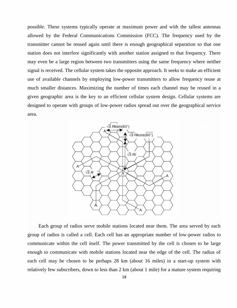
Each group of radios serve mobile stations located near them. The area served by each
group of radios is called a cell. Each cell has an appropriate number of low-power radios to
communicate within the cell itself. The power transmitted by the cell is chosen to be large
enough to communicate with mobile stations located near the edge of the cell. The radius of
each cell may be chosen to be perhaps 28 km (about 16 miles) in a start-up system with
relatively few subscribers, down to less than 2 km (about 1 mile) for a mature system requiring
19
considerable frequency reuse. As the traffic grows, new cells and channels are added to the
system. If an irregular cell pattern is selected, it would lead to an inefficient use of the spectrum
due to its inability to reuse frequencies because of cochannel interference. In addition, it would
also result in an uneconomical deployment of equipment, requiring relocation from one cell site
to another. Therefore, a great deal of engineering effort would be required to readjust the
transmission, switching, and control resources every time the system goes through its
development phase. The use of a regular cell pattern in a cellular system design eliminates all
these difficulties. In reality, cell coverage is an irregularly shaped circle. The exact coverage of
the cell depends on the terrain and many other factors. For design purposes and as a first-order
approximation, we assume that the coverage areas are regular polygons. For example, for
omnidirectional antennas with constant signal power, each cell site coverage area would be
circular. To achieve full coverage without dead spots, a series of regular polygons are required
for cell sites.
Any regular polygon such as an equilateral triangle, a square, or a hexagon can be used
for cell design. The hexagon is used for two reasons: a hexagonal layout requires fewer cells
and, therefore, fewer transmitter sites, and a hexagonal cell layout is less expensive compared
to square and triangular cells. In practice, after the polygons are drawn on a map of the
coverage area, radial lines are drawn and the signal-to-noise ratio (SNR) calculated for various
directions using the propagation models, or using appropriate computer programs.we assume
regular polygons for coverage areas even though in practice that is only an approximation.
Handoff Strategies
When a mobile moves into a different cell while a conversation is in progress, the MSC
automatically transfers the call to a new channel belonging to the new base station. This
handoff operation not only involves a new base station, but also requires that the voice and
control signals be allocated to channels associated with the new base station. Another feature of
newer cellular systems is the ability to make handoff decisions based on a wide range of
metrics other than signal strength. The cochannel and adjacent channel interference levels may
20
be measured at the base station or the mobile, and this information may be used with
conventional signal strength data to provide a multi-dimensional algorithm for determining
when a handoff is needed. The IS-95 code division multiple access (CDMA) spread spectrum
cellular system described provides a unique handoff capability that cannot be provided with
other wireless systems. Unlike channelized wireless systems that assign different radio
channels during a handoff (called a hard handoff), spread spectrum mobiles share the same
channel in every cell. Thus, the term handoff does not mean a physical change in the assigned
channel, but rather that a different base station handles the radio communication task. By
simultaneously evaluating the received signals from a single subscriber at several neighboring
base stations, the MSC may actually decide which version of the user's signal is best at any
moment in time. This technique exploits macroscopic space diversity provided by the different
physical locations of the base stations and allows the MSC to make a "soft" decision as to
which version of the user's signal to pass along to the PSTN at any instance EPad94]. The
ability to select between the instantaneous received signals from a variety of base stations is
called soft handoff. Since CDMA uses cochannel cells, it can use macroscopic spatial diversity
to provide soft handoff. Soft handoff is performed by the MSC, which can simultaneously
monitor a particular user from two or more base stations. The MSC may choose the best
version of the signal at any time without switching frequencies.
Types of Hand – off:
1st generation handoff, MAHO (Mobile assisted handoff), Intersystem handoff, Guard
channel concept, Umbrella approach, Soft and hard handoff, Cell dragging
2. What are the differences between TDMA, FDMA and CDMA? Explain in detail about
each multiple access techniques. (16) (June 2014)
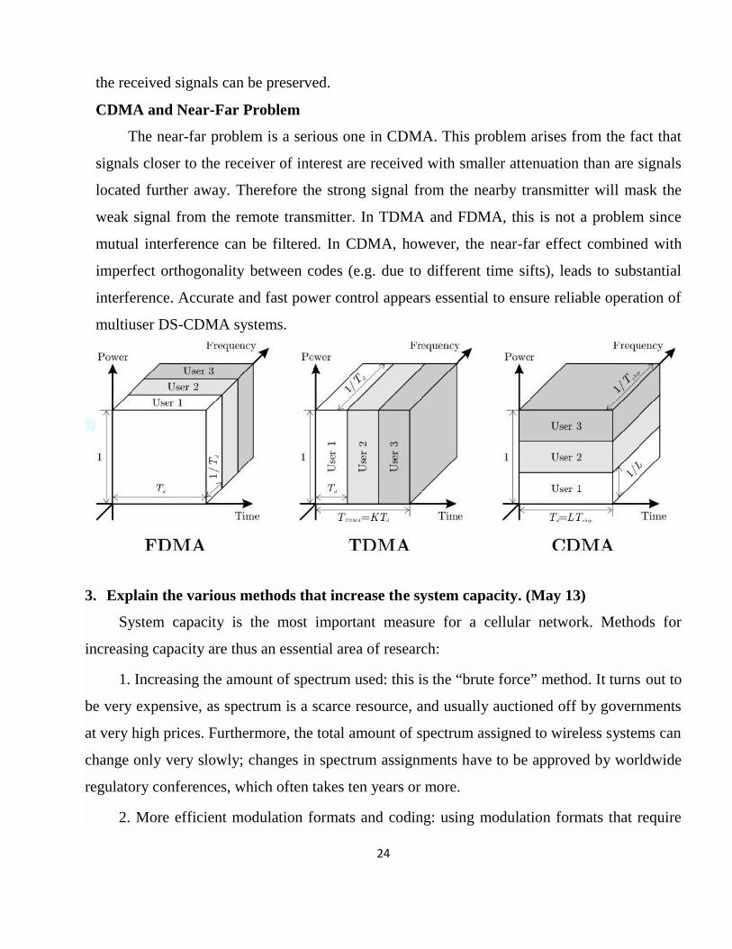
Frequency Division Multiple Access
The FDMA is the simplest scheme used to provide multiple access. It separates different
users by assigning a different carrier frequency. Multiple users are isolated using bandpass
filters. In FDMA, signals from various users are assigned different frequencies, just as in an
analog system. Frequency guard bands are provided between adjacent signal spectra to
21
minimize crosstalk between adjacent channels. The advantages and disadvantages of FDMA
with respect to TDMA or CDMA are:
Advantages
1. Capacity can be increased by reducing the information bit rate and using an efficient digital
speech coding scheme.
2. Technological advances required for implementation are simple. A system can be
configured so that improvements in terms of a lower bit rate speech coding could be easily
incorporated.
3. Hardware simplicity, because multiple users are isolated by employing simple bandpass
filters.
Disadvantages
1. The system architecture based on FDMA was implemented in firstgeneration analog
systems such as advanced mobile phone system (AMPS) or total access communication
system (TACS). The improvement in capacity depends on operation at a reduced signal-to-
interference (S/I) ratio. But the narrowband digital approach gives only limited advantages in
this regard so that modest capacity improvements could be expected from the allocated
spectrum.
2. The maximum bit-rate per channel is fixed and small, inhibiting the flexibility in bit-rate
capability that may be a requirement for computer fi le transfer in some applications in the
future.
3. Inefficient use of spectrum, in FDMA if a channel is not in use, it remains idle and cannot
be used to enhance the system capacity.
4. Crosstalk arising from adjacent channel interference is produced by nonlinear effects.
Time Division Multiple Access
In a TDMA system, each user uses the whole channel bandwidth for a fraction of time
compared to an FDMA system where a single user occupies the channel bandwidth for the
entire duration. In a TDMA system, time is divided into equal time intervals, called slots.
User data is transmitted in the slots. Several slots make up a frame. Guard times are used
between each user’s transmission to minimize crosstalk between channels. Each user is
22
assigned a frequency and a time slot to transmit data. The data is transmitted via a radio-
carrier from a base station to several active mobiles in the downlink. In the reverse direction
(uplink), transmission from mobiles to base stations is time-sequenced and synchronized on a
common frequency for TDMA. The preamble carries the address and synchronization
information that both the base station and mobile stations use for identification. In a TDMA
system, the user can use multiple slots to support a wide range of bit rates by selecting the
lowest multiplexing rate or multiple of it. This enables supporting a variety of voice coding
techniques at different bit rates with different voice qualities. Similarly, data communications
customers could use the same kinds of schemes, choosing and paying for the digital data rate
as required. This would allow customers to request and pay for a bandwidth on demand.
Depending on the data rate used and the number of slots per frame, a DMA system can use
the entire bandwidth of the system or can employ an FDD scheme. The resultant multiplexing
is a mixture of frequency division and time division. The entire frequency band is divided
into a number of duplex channels (about 350 to 400 kHz). These channels are deployed in a
frequency-reuse pattern, in which radio-port frequencies are assigned using an autonomous
adaptive frequency assignment algorithm. Each channel is configured in a TDM mode for the
downlink direction and a TDMA mode for the uplink direction.
The advantages and disadvantages of TDMA are:
Advantages
1. TDMA permits a flexible bit rate, not only for multiples of the basic single channel rate but
also submultiples for low bit rate broadcast-type traffic.
2. TDMA offers the opportunity for frame-by-frame monitoring of signal strength/bit error
rates to enable either mobiles or base stations to initiate and execute handoffs.
3. TDMA, when used exclusively and not with FDMA, utilizes bandwidth more efficiently
because no frequency guard band is required between channels.
4. TDMA transmits each signal with sufficient guard time between time slots to
accommodate time inaccuracies because of clock instability, delay spread, transmission delay
because of propagation distance, and the tails of signal pulse because of transient responses.
Disadvantages
23
1. For mobiles and particularly for hand-sets, TDMA on the uplink demands high peak power
in transmit mode that shortens battery life.
2. TDMA requires a substantial amount of signal processing for matched filtering and
correlation detection for synchronizing with a time slot.
3. TDMA requires synchronization. If the time slot synchronization is lost, the channels may
collide with each other.
4. One complicating feature in a TDMA system is that the propagation time for a signal from
a mobile station to a base station varies with its distance to the base station.
Code Division Multiple Access
In CDMA, the same bandwidth is occupied by all the users, however they are all
assigned separate codes, which differentiates them from each other. CDMA utilize a spread
spectrum technique in which a spreading signal (which is uncorrelated to the signal and has a
large bandwidth) is used to spread the narrow band message signal. Direct Sequence Spread
Spectrum (DS-SS) This is the most commonly used technology for CDMA. In DS-SS, the
message signal is multiplied by a Pseudo Random Noise Code. Each user is given his own
codeword which is orthogonal to the codes of other users and in order to detect the user, the
receiver must know the codeword used by the transmitter. There are, however, two problems
in such systems which are discussed in the sequel. CDMA/FDD in IS-95 In this standard, the
frequency range is: 869-894 MHz (for Rx) and 824-849 MHz (for Tx). In such a system,
there are a total of 20 channels and 798 users per channel. For each channel, the bit rate is
1.2288 Mbps. For orthogonality, it usually combines 64 Walsh-Hadamard codes and a m-
sequence.
CDMA and Self-interference Problem
In CDMA, self-interference arises from the presence of delayed replicas of signal due to
multipath. The delays cause the spreading sequences of the different users to lose their
orthogonality, as by design they are orthogonal only at zero phase offset. Hence in
despreading a given user’s waveform, nonzero contributions to that user’s signal arise from
the transmissions of the other users in the network. This is distinct from both TDMA and
FDMA, wherein for reasonable time or frequency guardbands, respectively, orthogonality of
24
the received signals can be preserved.
CDMA and Near-Far Problem
The near-far problem is a serious one in CDMA. This problem arises from the fact that
signals closer to the receiver of interest are received with smaller attenuation than are signals
located further away. Therefore the strong signal from the nearby transmitter will mask the
weak signal from the remote transmitter. In TDMA and FDMA, this is not a problem since
mutual interference can be filtered. In CDMA, however, the near-far effect combined with
imperfect orthogonality between codes (e.g. due to different time sifts), leads to substantial
interference. Accurate and fast power control appears essential to ensure reliable operation of
multiuser DS-CDMA systems.
3. Explain the various methods that increase the system capacity. (May 13)
System capacity is the most important measure for a cellular network. Methods for
increasing capacity are thus an essential area of research:
1. Increasing the amount of spectrum used: this is the “brute force” method. It turns out to
be very expensive, as spectrum is a scarce resource, and usually auctioned off by governments
at very high prices. Furthermore, the total amount of spectrum assigned to wireless systems can
change only very slowly; changes in spectrum assignments have to be approved by worldwide
regulatory conferences, which often takes ten years or more.
2. More efficient modulation formats and coding: using modulation formats that require
25
less bandwidth (higher order modulation) and/or are more resistant to interference. The former
allows an increase in data rate for each user (or an increase in the number of users in a cell
while keeping the data rate per user constant). However, the possible benefits of higher order
modulation are limited: they are more sensitive to noise and interference, so that the reuse
distance might have to be increased. The use of interference-resistant modulation allows a
reduction in reuse distance. The introduction of near-capacity-achieving codes – turbo codes
and low-density parity check codes – is another way of achieving better immunity to
interference, and thus increases system capacity.
3. Better source coding: depending on required speech quality, current speech coders need
data rates between 32 kbit/s and 4 kbit/s. Better models for the properties of speech allow the
data rate to be decreased without decreasing quality. Compression of data files and music/video
compression also allows more users to be served.
4. Discontinuous Voice Transmission DTX: exploits the fact that during a phone
conversation each participant talks only 50% of the time. A TDMA system can thus set up
more calls than there are available timeslots. During the call, the users that are actively talking
at the moment are multiplexed onto the available timeslots, while quiet users do not get
assigned any radio resources.
5. Multiuser detection: this greatly reduces the effect of interference, and thus allows
more users per cell for CDMA systems or smaller reuse distances for FDMA systems
6. Adaptive modulation and coding: employs the knowledge at the TX of the transmission
channel, and chooses the modulation format and coding rate that are “just right” for the current
link situation. This approach makes better use of available power, and, among other effects,
reduces interference.
7. Reduction of cell radius: this is an effective, but very expensive, way of increasing
capacity, as a new BS has to be built for each additional cell. For FDMA systems, it also means
that the frequency planning for a large area has to be redone.Furthermore, smaller cells also
require more handovers for moving users, which is complicated, and reduces spectral
efficiency due to the large amount of signaling information that has to be sent during a
26
handover.
8. Use of sector cells: a hexagonal (or similarly shaped) cell can be divided into several
(typically three) sectors. Each sector is served by one sector antenna. Thus, the number of cells
has tripled, as has the number of BS antennas. However, the number of BS locations has
remained the same, because the three antennas are at the same location.
9. Use of an overlay structure: an overlay structure combines cells with different size and
different traffic density. Therefore, some locations may be served by several BSs
simultaneously. An umbrella cell provides basic coverage for a large area. Within that coverage
area, multiple microcells are placed in areas of high traffic density. Within the coverage area of
the microcells, most users are served by the microcell BS, but fast-moving users are assigned to
the umbrella cell, in order to reduce the number of handovers between cells.
4. What are the features of interference limited systems.
Interference Limited Systems
Noise-Limited Systems
Wireless systems are required to provide a certain minimum transmission quality .This
transmission quality in turn requires a minimum Signal-to-Noise Ratio (SNR) at the receiver
(RX). Consider now a situation where only a single BS transmits, and a Mobile Station (MS)
receives; thus, the performance of the system is determined only by the strength of the (useful)
signal and the noise. As the MS moves further away from the BS, the received signal power
decreases, and at a certain distance, the SNR does not achieve the required threshold for
reliable communications. Therefore, the range of the system is noise limited. Depending on the
interpretation, it is too much noise or too little signal power that leads to bad link quality.
Let us assume for the moment that the received power decreases with d2, the square of the
distance
distance between BS and MS. More precisely, let the received power
(1.1)
27
where GRX and GTX are the gains of the receive and transmit antennas, respectively,1 /λ is the
wavelength, and PTX is the transmit power.
The noise that disturbs the signal can consist of several components, as follows:
1. Thermal noise: The power spectral density of thermal noise depends on the environmental
temperature Te that the antenna “sees.” The temperature of the Earth is around 300 K, while
the temperature of the (cold) sky is approximately Te ≈ 4K (the temperature in the direction
of the Sun is of course much higher). As a first approximation, it is usually assumed that the
environmental temperature is isotropically 300 K. Noise power spectral density is then
(1.2)
where kB is Boltzmann’s constant, kB = 1.38 x 10⁻²³ J/K, and the noise power is
Pn = N0B (1.3)
where B is RX bandwidth (in units of Hz). It is common to write Eq. (1.2) using logarithmic
units (power P expressed in units of dBm is 10 log10 (P/1 mW)):
N0 = −174 dBm/Hz (1.4)
This means that the noise power contained in a 1-Hz bandwidth is −174 dBm. The noise power
contained in bandwidth B is
−174 + 10 log10(B) dBm (1.5)
The logarithm of bandwidth B, specifically 10 log10(B), has the units dBHz.
2. Man-made noise: We can distinguish two types of man-made noise:
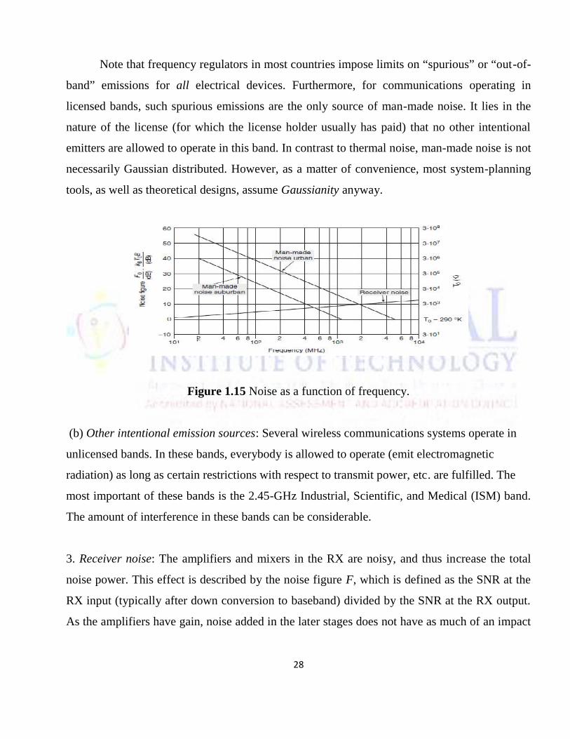
(a) Spurious emissions: Many electrical appliances as well as radio transmitters (TXs) designed
for other frequency bands have spurious emissions over a large bandwidth that includes the
frequency range in which wireless communications systems operate. For urban outdoor
environments, car ignitions and other impulse sources are especially significant sources of
noise. In contrast to thermal noise, the noise created by impulse sources decreases with
frequency (see Figure 1.15). At 150 MHz, it can be 20 dB stronger than thermal noise; at
900 MHz, it is typically 10 dB stronger.
28
Note that frequency regulators in most countries impose limits on “spurious” or “out-of-
band” emissions for all electrical devices. Furthermore, for communications operating in
licensed bands, such spurious emissions are the only source of man-made noise. It lies in the
nature of the license (for which the license holder usually has paid) that no other intentional
emitters are allowed to operate in this band. In contrast to thermal noise, man-made noise is not
necessarily Gaussian distributed. However, as a matter of convenience, most system-planning
tools, as well as theoretical designs, assume Gaussianity anyway.
Figure 1.15 Noise as a function of frequency.
(b) Other intentional emission sources: Several wireless communications systems operate in
unlicensed bands. In these bands, everybody is allowed to operate (emit electromagnetic
radiation) as long as certain restrictions with respect to transmit power, etc. are fulfilled. The
most important of these bands is the 2.45-GHz Industrial, Scientific, and Medical (ISM) band.
The amount of interference in these bands can be considerable.
3. Receiver noise: The amplifiers and mixers in the RX are noisy, and thus increase the total
noise power. This effect is described by the noise figure F, which is defined as the SNR at the
RX input (typically after down conversion to baseband) divided by the SNR at the RX output.
As the amplifiers have gain, noise added in the later stages does not have as much of an impact
29
as noise added in the first stage of the RX. Mathematically, the total noise figure Feq of a
cascade of components is
(1.6)
where Fi and Gi are noise figures and noise gains of the individual stages in absolute units (not
in decibels (dB)). Note that for this equation, passive components, like attenuators with gain m
< 1, can be interpreted as either having a noise figure of F = 1/m and unit gain of
G =1,or unit noise figure F = 1, and gain G = m.
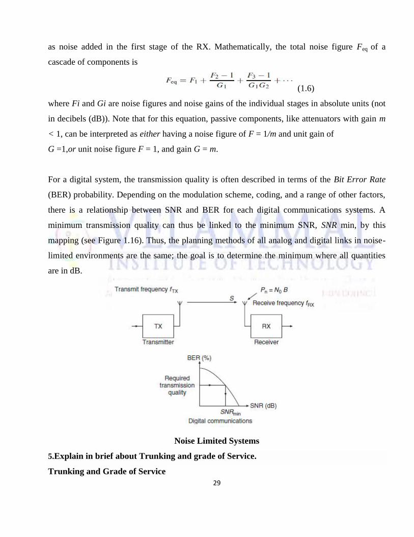
For a digital system, the transmission quality is often described in terms of the Bit Error Rate
(BER) probability. Depending on the modulation scheme, coding, and a range of other factors,
there is a relationship between SNR and BER for each digital communications systems. A
minimum transmission quality can thus be linked to the minimum SNR, SNR min, by this
mapping (see Figure 1.16). Thus, the planning methods of all analog and digital links in noise-
limited environments are the same; the goal is to determine the minimum where all quantities
are in dB.
Noise Limited Systems
5.Explain in brief about Trunking and grade of Service.
Trunking and Grade of Service
30
The concept of trunking allows a large number of users to share the relatively small
number of channels in a cell by providing access to each user, on demand, from a pool of
available channels. In a trunked radio system, each user is allocated a channel on a per call
basis, and upon termination of the call, the previously occupied channel is immediately
returned to the pool of available channels.
The telephone company uses trunking theory to determine to determine the number of
telephone circuits that need to be allocated for office buildings with hundreds of telephones ,
and this same principle is used in designing cellular radio systems. In a trunked mobile radio
system, when a particular user requests service and all of the radio channels are already in use,
the user is blocked, or denied access to the system. To design trunked radio systems that can
handle a specific capacity at a specific “grade of service”, it is essential to understand trunking
theory and queuing theory.
The grade of service (GOS) is a measure of the ability of a user to access a trunked
system during the busiest hour. The busy hour is based upon customer demand at the busiest
hour during a week, month or a year. The grade of service is a bench mark used to define the
desired performance of a particular trunked system by specifying a desired likelihood of a user
obtaining channel access given a specific number of channels available in a system. GOS is
typically given as the likelihood that a call is blocked, or the likelihood of a call experiencing a
delay greater than a certain queuing time.
The traffic intensity offered by each user is equal to the call request rate multiplied bythe call holding time.
Au = λH
Where H is the average duration of a call and λ is the average number of call requests per unittime for each user.
For a system containing U users and an unspecified number of channel, the total offeredtraffic intensity A, is given as
A = U Au
31
Furthermore, in a C channel trunked system, if the traffic is equally distributed amongthe channels, then the traffic intensity per channel, Ac, is given as
Ac = U Au/C
There are two types of trunked systems which are commonly used.
(1) Blocked calls cleared(2) Blocked calls delayed
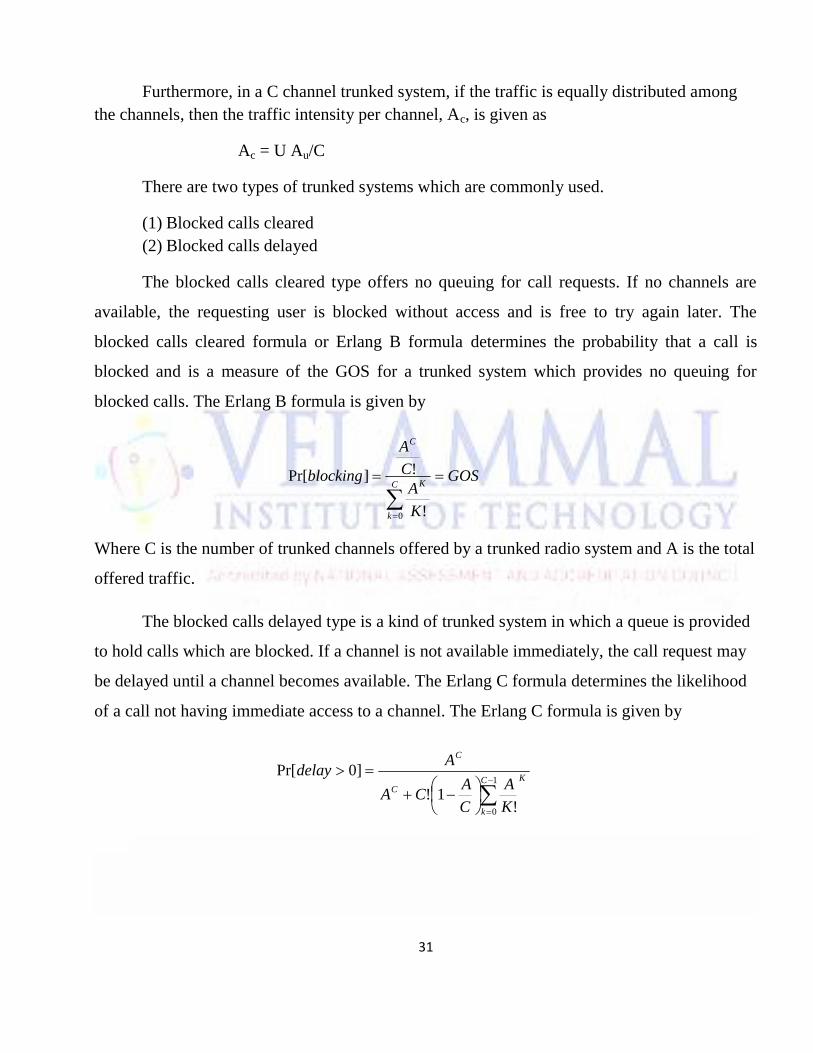
The blocked calls cleared type offers no queuing for call requests. If no channels are
available, the requesting user is blocked without access and is free to try again later. The
blocked calls cleared formula or Erlang B formula determines the probability that a call is
blocked and is a measure of the GOS for a trunked system which provides no queuing for
blocked calls. The Erlang B formula is given by
GOS
K
AC
A
blockingC
k
K
C
0 !
!]Pr[
Where C is the number of trunked channels offered by a trunked radio system and A is the total
offered traffic.
The blocked calls delayed type is a kind of trunked system in which a queue is provided
to hold calls which are blocked. If a channel is not available immediately, the call request may
be delayed until a channel becomes available. The Erlang C formula determines the likelihood
of a call not having immediate access to a channel. The Erlang C formula is given by
1
0 !1!
]0Pr[C
k
KC
C
K
A
C
ACA
Adelay
32
UNIT III DIGITAL SIGNALING FOR FADING CHANNELSPART-A
1. What are the main features of QPSK? (June 2014)
As with DSB -SC modulation, BPSSK requires a transmission bandwidth twice the
message bandwidth. Now, Channel bandwidth is a primary resource that should be
conserved, particularly in wireless communications.
2. List the advantages of GMSK. (Dec 2014)
The properties of the MSK signal are
The MSK signal should have a constant envelope and a relatively narrow bandwidth
3. List the advantages of third generation (3G) networks. (Dec 2014)
Another3G system based on CDMA is a direct sequence (OS) spread spectrum system in
which the entire bandwidth of the carrier channel is made available to each user
simultaneously.
4. Differentiate Cellular telephony and Cordless telephony.
A cordless telephone or portable telephone replaces the handset cord with a radio link.
The handset communicates with a base station connected to a fixed telephone line.
33
5. Compute the Rayleigh distance of a square Antenna with 20 dB gain.
The minimum range length to avoid this error is the Rayleigh distance:
A few trial calculations will show that miles of range can be required for large dishes.
Fortunately, the Rayleigh distance for the 25 inch dish which I wanted to measure is only
91 feet.
6. List out any two properties of wideband channel.
Radio channels are inherently barvl-limited, implying that they may be sampled at the
Nyquist rate. This result simplifies the simulation and analysis of complicated wideband
channels.
The wideband models treat the propagation channel as frequency -selective; different
frequency sub-bands have different channel responses
7. Draw the mathematical link model for analysis of modulation schemes.
Modulation is the process of varying one or more properties of a periodic waveform,
called the carrier signal, with a modulating signal which typically contains information to
be transmitted
8. Comment on the necessity of a Gaussian filter in GMSK.
The properties of the MSK signal are The MSK signal should have a constant envelope
and a relatively narrow bandwidth
9. Discuss the principle of OFDM modulation scheme.
Orthogonal frequency-division multiplexing (OFDM) is a method of encoding digital data
on multiple carrier frequencies.
10. Define cyclic prefix.(Dec 2012)
In OFDM, delay dispersion leads to a loss of orthogonality between the subcarriers and
thus leads to Inter Carrier Interference (ICI). These negative effects can be eliminated by
a special type of guard interval called the cyclic prefix.
34
Part – B
1. Explain MSK transmitter and receiver with signal space diagram and give an
expression for spectral efficiency. (June 13)
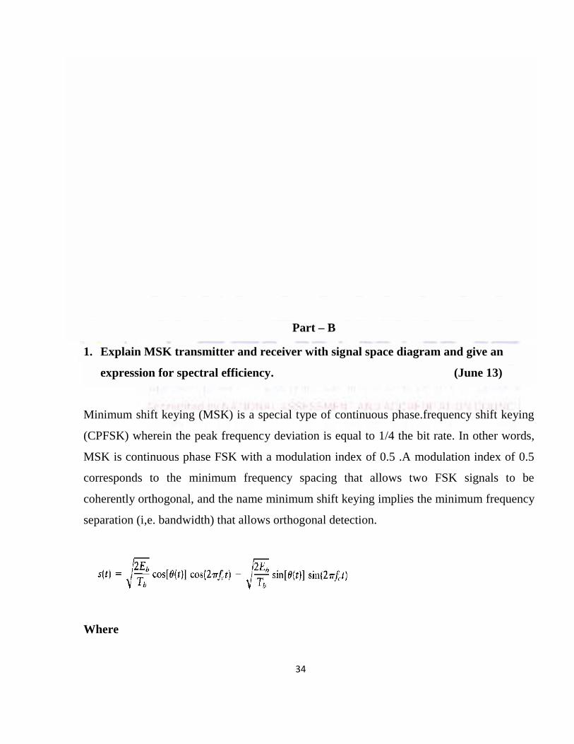
Minimum shift keying (MSK) is a special type of continuous phase.frequency shift keying
(CPFSK) wherein the peak frequency deviation is equal to 1/4 the bit rate. In other words,
MSK is continuous phase FSK with a modulation index of 0.5 .A modulation index of 0.5
corresponds to the minimum frequency spacing that allows two FSK signals to be
coherently orthogonal, and the name minimum shift keying implies the minimum frequency
separation (i,e. bandwidth) that allows orthogonal detection.
Where
35
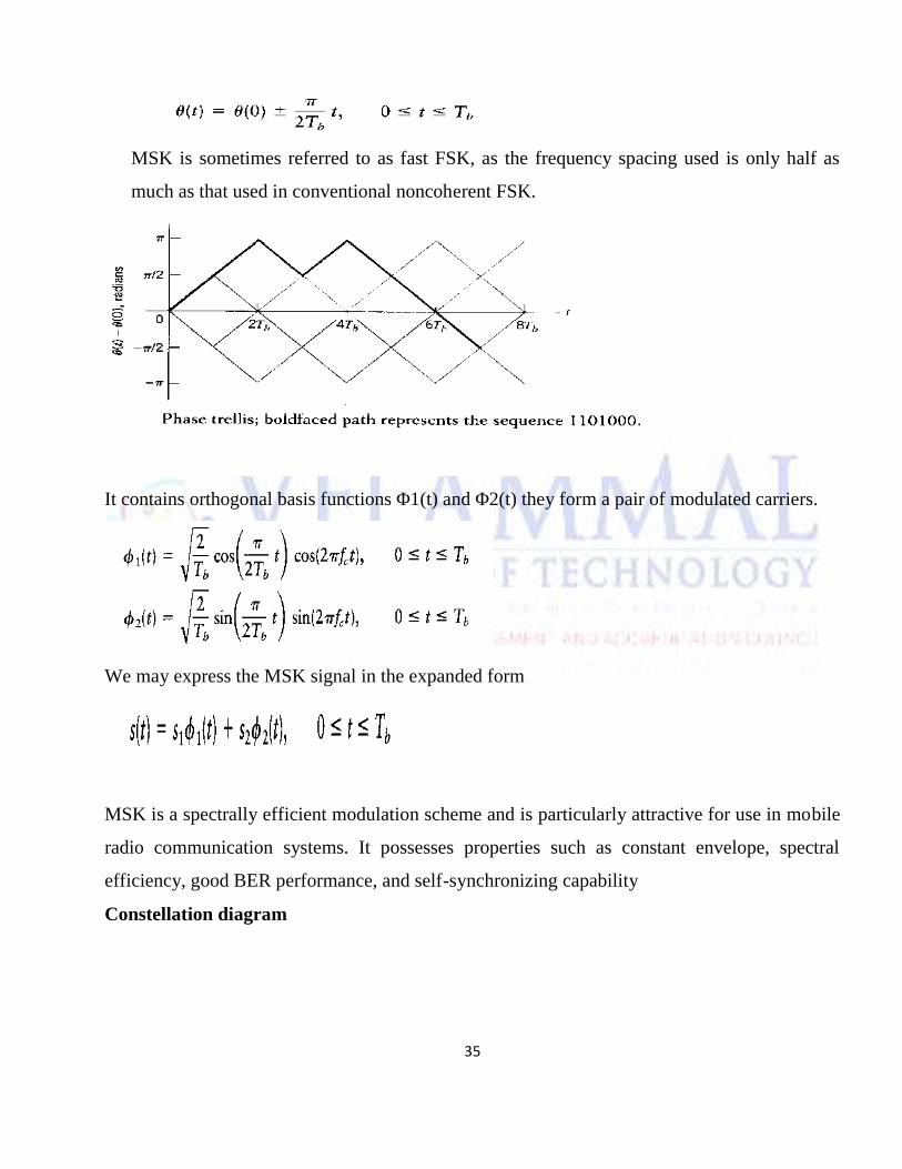
MSK is sometimes referred to as fast FSK, as the frequency spacing used is only half as
much as that used in conventional noncoherent FSK.
It contains orthogonal basis functions Φ1(t) and Φ2(t) they form a pair of modulated carriers.
We may express the MSK signal in the expanded form
MSK is a spectrally efficient modulation scheme and is particularly attractive for use in mobile
radio communication systems. It possesses properties such as constant envelope, spectral
efficiency, good BER performance, and self-synchronizing capability
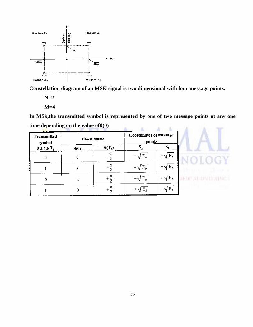
Constellation diagram
36
Constellation diagram of an MSK signal is two dimensional with four message points.
N=2
M=4
In MSk,the transmitted symbol is represented by one of two message points at any one
time depending on the value ofθ(0)
37
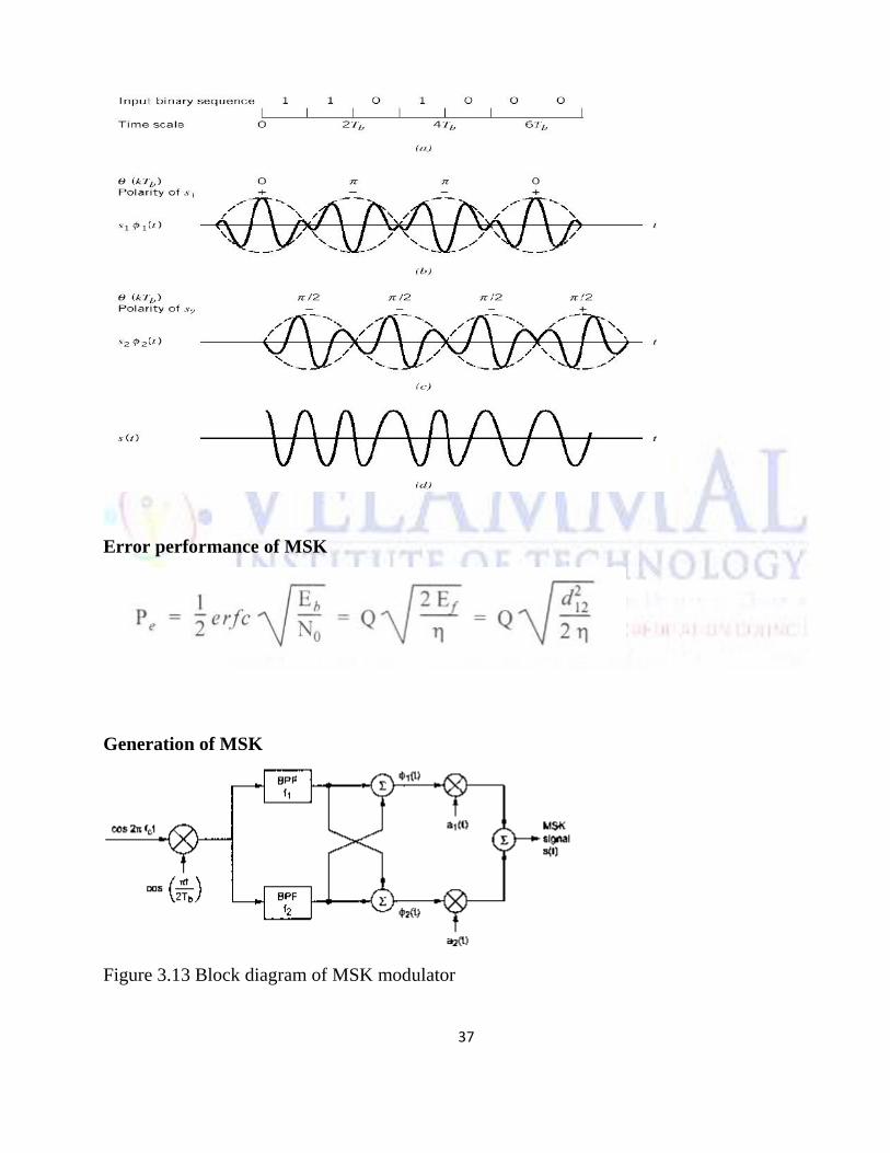
Error performance of MSK
Generation of MSK
Figure 3.13 Block diagram of MSK modulator
38
Figure 3.13 shows a typical MSK modulator. Multiplying a carrier signal with cos [π t/2T]
produces two phase-coherent signals at fc + 1 /4T and –fc + — I /4T. These two FSK signals
are separated using two narrow bandpass filters and appropriately combined to form the in-
phase and quadrature carrier components x(t) and y(t), respectively. These carriers are
multiplied with the odd and even bit streams, rnI(t) and mQ(t), to produce the MSK modulated
signal SMSK(t).
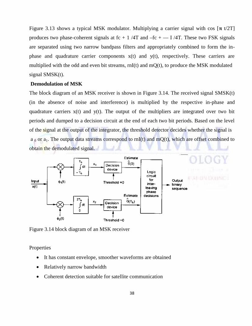
Demodulation of MSK
The block diagram of an MSK receiver is shown in Figure 3.14. The received signal SMSK(t)
(in the absence of noise and interference) is multiplied by the respective in-phase and
quadrature carriers x(t) and y(t). The output of the multipliers are integrated over two bit
periods and dumped to a decision circuit at the end of each two bit periods. Based on the level
of the signal at the output of the integrator, the threshold detector decides whether the signal is
a 0 or a1. The output data streams correspond to rnI(t) and mQ(t), which are offset combined to
obtain the demodulated signal.
Figure 3.14 block diagram of an MSK receiver
Properties
It has constant envelope, smoother waveforms are obtained
Relatively narrow bandwidth
Coherent detection suitable for satellite communication
39
Side lobes are zero outside the frequency band, so it has resistance to co-channel
interference
Advantages
1. Smoother waveform than QPSK
2. There is no amplitude variation, constant envelope.
3. Main lobe is wider, contains 99% of signal energy.
4. Less inter channel interference
5. Spectral efficiency is good; BER performance is suitable for mobile radio
communication systems.
Disadvantages
1. Complex circuits are needed for generation and detection of MSK signal.
2. Main lobe of MSK is wide
3. Slow decay of MSK power spectral density creates adjacent channel interference.
4. Not suitable for multi user communications
5. Bandwidth required is higher than that of QPSK scheme.
2. Explain with neat diagram QPSK transmission and reception technique and their
significance in wireless system. (16) (June 2014)
Quadrature-Phase Shift Keying
A Quadrature-Phase Shift Keying (QPSK)-modulated signal is a PAM where the signal
carries bit per symbol interval on both the in-phase and quadrature-phase component. The
original data stream is split into two streams, b1i and b2i:
each of which has a data rate that is half that of the original data stream:
40
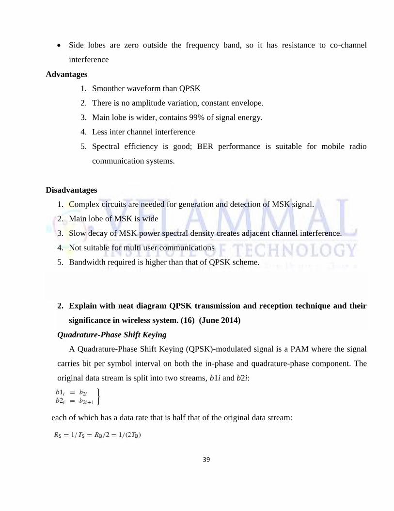
Let us first consider the situation where basis pulses are rectangular pulses, g(t) = gR(t, TS).
Then we can give an interpretation of QPSK as either a phase modulation or as a PAM. We
first define two sequences of pulses
When interpreting QPSK as a PAM, the bandpass signal reads
Normalization is done in such a way that the energy within one symbol interval is 2EB,
where EB is the energy expended on transmission of a bit. The baseband signal is
When interpreting QPSK as a phase modulation, the low-pass signal can be written as
√2EB/TB exp(jΦS(t)) with:
It is obvious from this representation that the signal is constant envelope, except for the transition at t= iTS
Signal space diagram of quadrature-phaseshift keying.
Normalized power-spectral density ofquadrature-phase shift keying.
41
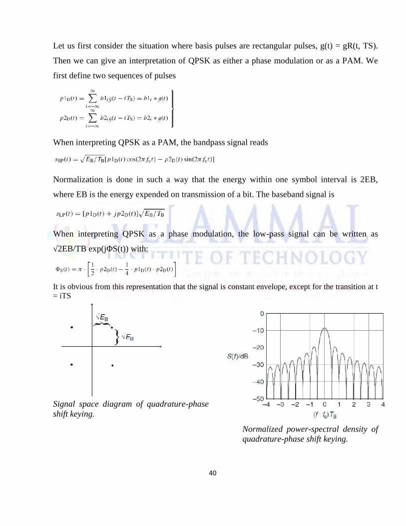
QPSK Transmission
Figure 3.4 shows a block diagram of a typical QPSK transmitter. The unipolar binary
message stream has bit rate Rb and is first converted into a bipolar non-return-to-zero (NRZ)
sequence using a unipolar to bipolar convener. The bit stream m (t) is then split into two bit
streams mI (t) and mQ (t) (in-phase and quadrature streams), each having a bit rate of Rs =
Rb/2. The bit stream m1 (t) is called the "even" stream and mQ (t) is called the "odd" stream.
The two binary sequences are separately modulated by two carriers Φ1(t) and Φ2(t) which
are in quadrature. The two modulated signals, each of which can be considered to be a BPSK
signal, are summed to produce a QPSK signal.
The filter at the output of the modulator confines the power spectrum of the QPSK signal
within the allocated band. This prevents spill-over of signal energy into adjacent channels and
also removes out-of-band spurious signals generated during the modulation process. In most
implementations, pulse shaping is done at baseband to provide proper RF filtering at the
transmitter output.
Block diagram of a QPSK transmitter.
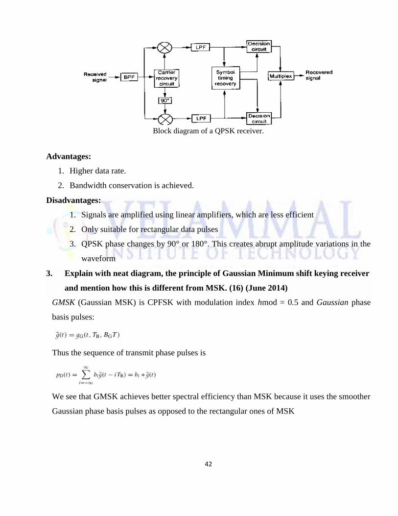
Figure 3.5 shows a block diagram of a coherent QPSK receiver. The frontend bandpass filter
removes the out-of-band noise and adjacent channel interference. The filtered output is split
into two parts, and each part is coherently demodulated using the in-phase and quadrature
carriers. The coherent carriers used for demodulation are recovered from the received signal
using carrier recovery circuits. The outputs of the demodulators are passed through decision
circuits which generate the in-phase and quadrature binary streams. The two components are
then multiplexed to reproduce the original binary sequence.
42
Block diagram of a QPSK receiver.
Advantages:
1. Higher data rate.
2. Bandwidth conservation is achieved.
Disadvantages:
1. Signals are amplified using linear amplifiers, which are less efficient
2. Only suitable for rectangular data pulses
3. QPSK phase changes by 90° or 180°. This creates abrupt amplitude variations in the
waveform
3. Explain with neat diagram, the principle of Gaussian Minimum shift keying receiver
and mention how this is different from MSK. (16) (June 2014)
GMSK (Gaussian MSK) is CPFSK with modulation index hmod = 0.5 and Gaussian phase
basis pulses:
Thus the sequence of transmit phase pulses is
We see that GMSK achieves better spectral efficiency than MSK because it uses the smoother
Gaussian phase basis pulses as opposed to the rectangular ones of MSK
43
GMSK is a simple binary modulation scheme. The side lobe levels of the spectrum are much
reduced by passing the modulating NRZ data waveform through a pre-modulation Gaussian
pulse-shaping filter. Gaussian refers to the shape of filter. GMSK has excellent power
efficiency and spectral efficiency than conventional FSK.
Properties of Gaussian filter
Suppress the high frequency components of the transmitted signal
Avoids excessive deviations in the instantaneous frequency of the FM signal
Detect coherently or non-coherently the GMSK signal
Gaussian filter is used before the modulator to reduce the transmitting bandwidth
of the signal.
Features
It has excellent power efficiency due to the constant envelope and it has excellent
spectral efficiency.
The pre-modulation Gaussian filtering introduces ISI in the transmitted signal. But the
degradation is not severe if 3dB bandwidth bit duration product of the filter is greater
than 0.5.
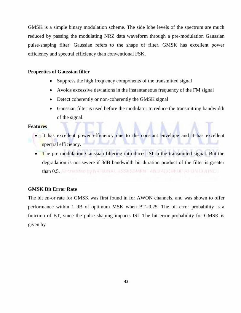
GMSK Bit Error Rate
The bit en-or rate for GMSK was first found in for AWON channels, and was shown to offer
performance within 1 dB of optimum MSK when BT=0.25. The bit error probability is a
function of BT, since the pulse shaping impacts ISI. The bit error probability for GMSK is
given by
44
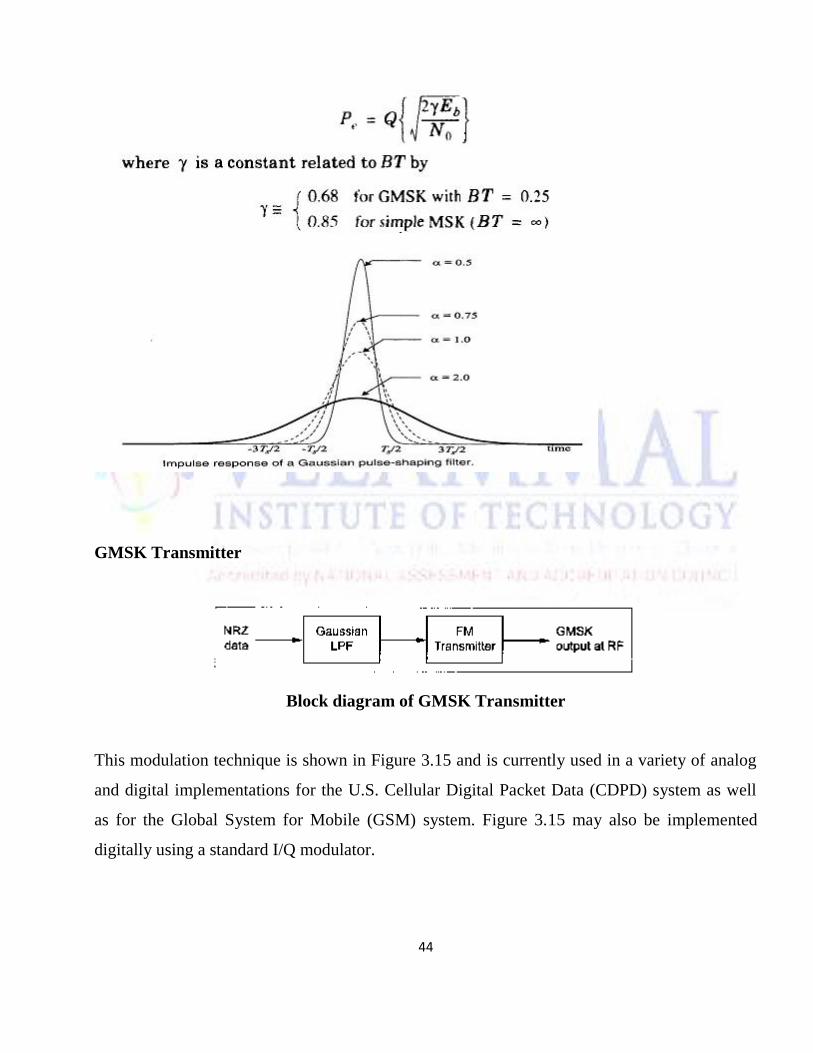
GMSK Transmitter
Block diagram of GMSK Transmitter
This modulation technique is shown in Figure 3.15 and is currently used in a variety of analog
and digital implementations for the U.S. Cellular Digital Packet Data (CDPD) system as well
as for the Global System for Mobile (GSM) system. Figure 3.15 may also be implemented
digitally using a standard I/Q modulator.
45
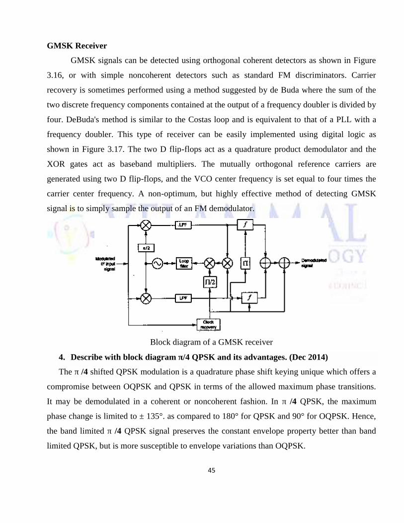
GMSK Receiver
GMSK signals can be detected using orthogonal coherent detectors as shown in Figure
3.16, or with simple noncoherent detectors such as standard FM discriminators. Carrier
recovery is sometimes performed using a method suggested by de Buda where the sum of the
two discrete frequency components contained at the output of a frequency doubler is divided by
four. DeBuda's method is similar to the Costas loop and is equivalent to that of a PLL with a
frequency doubler. This type of receiver can be easily implemented using digital logic as
shown in Figure 3.17. The two D flip-flops act as a quadrature product demodulator and the
XOR gates act as baseband multipliers. The mutually orthogonal reference carriers are
generated using two D flip-flops, and the VCO center frequency is set equal to four times the
carrier center frequency. A non-optimum, but highly effective method of detecting GMSK
signal is to simply sample the output of an FM demodulator.
Block diagram of a GMSK receiver
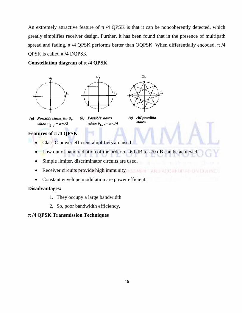
4. Describe with block diagram π/4 QPSK and its advantages. (Dec 2014)
The π /4 shifted QPSK modulation is a quadrature phase shift keying unique which offers a
compromise between OQPSK and QPSK in terms of the allowed maximum phase transitions.
It may be demodulated in a coherent or noncoherent fashion. In π /4 QPSK, the maximum
phase change is limited to ± 135°. as compared to 180° for QPSK and 90° for OQPSK. Hence,
the band limited π /4 QPSK signal preserves the constant envelope property better than band
limited QPSK, but is more susceptible to envelope variations than OQPSK.
46
An extremely attractive feature of π /4 QPSK is that it can be noncoherently detected, which
greatly simplifies receiver design. Further, it has been found that in the presence of multipath
spread and fading, π /4 QPSK performs better than OQPSK. When differentially encoded, π /4
QPSK is called π /4 DQPSK
Constellation diagram of π /4 QPSK
Features of π /4 QPSK
Class C power efficient amplifiers are used
Low out of band radiation of the order of -60 dB to -70 dB can be achieved
Simple limiter, discriminator circuits are used.
Receiver circuits provide high immunity
Constant envelope modulation are power efficient.
Disadvantages:
1. They occupy a large bandwidth
2. So, poor bandwidth efficiency.
π /4 QPSK Transmission Techniques
47
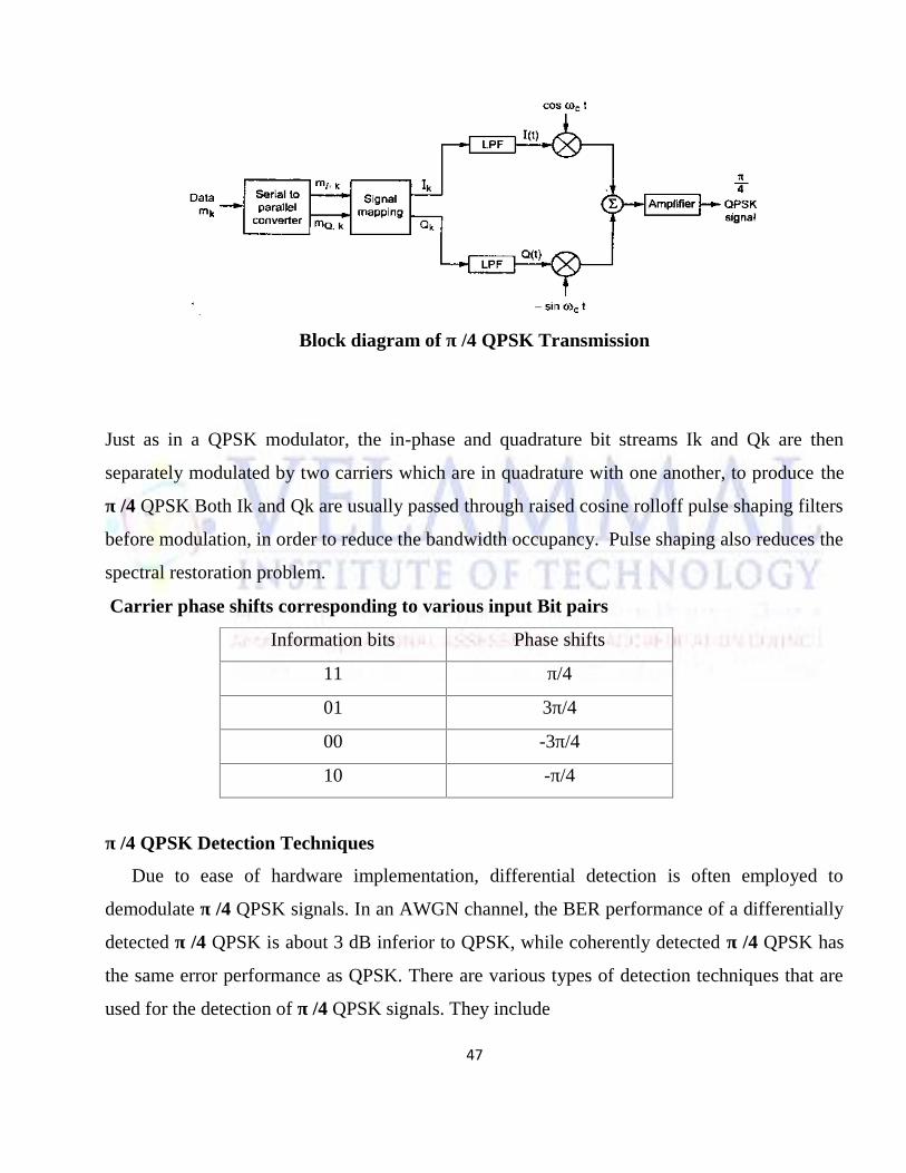
Block diagram of π /4 QPSK Transmission
Just as in a QPSK modulator, the in-phase and quadrature bit streams Ik and Qk are then
separately modulated by two carriers which are in quadrature with one another, to produce the
π /4 QPSK Both Ik and Qk are usually passed through raised cosine rolloff pulse shaping filters
before modulation, in order to reduce the bandwidth occupancy. Pulse shaping also reduces the
spectral restoration problem.
Carrier phase shifts corresponding to various input Bit pairs
Information bits Phase shifts
11 π/4
01 3π/4
00 -3π/4
10 -π/4
π /4 QPSK Detection Techniques
Due to ease of hardware implementation, differential detection is often employed to
demodulate π /4 QPSK signals. In an AWGN channel, the BER performance of a differentially
detected π /4 QPSK is about 3 dB inferior to QPSK, while coherently detected π /4 QPSK has
the same error performance as QPSK. There are various types of detection techniques that are
used for the detection of π /4 QPSK signals. They include
48
1. Baseband differential detection,
2. IF differential detection,and
3. FM discriminator detection.
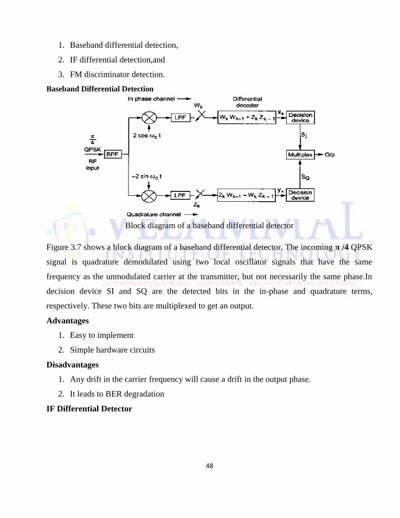
Baseband Differential Detection
Block diagram of a baseband differential detector
Figure 3.7 shows a block diagram of a baseband differential detector. The incoming π /4 QPSK
signal is quadrature demodulated using two local oscillator signals that have the same
frequency as the unmodulated carrier at the transmitter, but not necessarily the same phase.In
decision device SI and SQ are the detected bits in the in-phase and quadrature terms,
respectively. These two bits are multiplexed to get an output.
Advantages
1. Easy to implement
2. Simple hardware circuits
Disadvantages
1. Any drift in the carrier frequency will cause a drift in the output phase.
2. It leads to BER degradation
IF Differential Detector
49
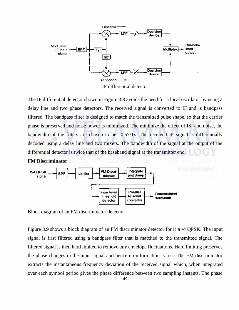
IF differential detector
The IF differential detector shown in Figure 3.8 avoids the need for a local oscillator by using a
delay line and two phase detectors. The received signal is converted to IF and is bandpass
filtered. The bandpass filter is designed to match the transmitted pulse shape, so that the carrier
phase is preserved and noise power is minimized. The minimize the effect of IS! and noise, the
bandwidth of the filters are chosen to be 0.57/Ts. The received IF signal is differentially
decoded using a delay line and two mixers. The bandwidth of the signal at the output of the
differential detector is twice that of the baseband signal at the transmitter end.
FM Discriminator
Block diagram of an FM discriminator detector
Figure 3.9 shows a block diagram of an FM discriminator detector for it π /4 QPSK. The input
signal is first filtered using a bandpass filter that is matched to the transmitted signal. The
filtered signal is then hard limited to remove any envelope fluctuations. Hard limiting preserves
the phase changes in the input signal and hence no information is lost. The FM discriminator
extracts the instantaneous frequency deviation of the received signal which, when integrated
over each symbol period gives the phase difference between two sampling instants. The phase
50
difference is then detected by a four level threshold comparator to obtain the original signal.
The phase difference can also be detected using a modulo-2 π phase detector. The modulo-2 π
phase detector improves the BER performance and reduces the effect of click noise.
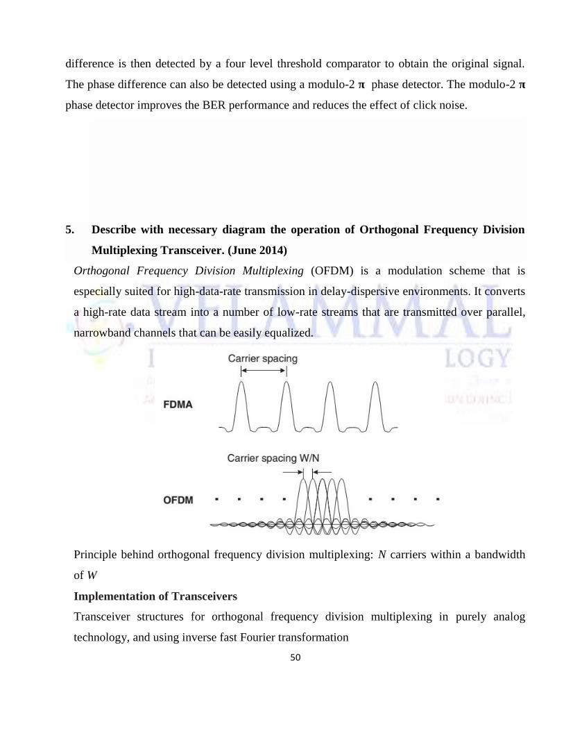
5. Describe with necessary diagram the operation of Orthogonal Frequency Division
Multiplexing Transceiver. (June 2014)
Orthogonal Frequency Division Multiplexing (OFDM) is a modulation scheme that is
especially suited for high-data-rate transmission in delay-dispersive environments. It converts
a high-rate data stream into a number of low-rate streams that are transmitted over parallel,
narrowband channels that can be easily equalized.
Principle behind orthogonal frequency division multiplexing: N carriers within a bandwidth
of W
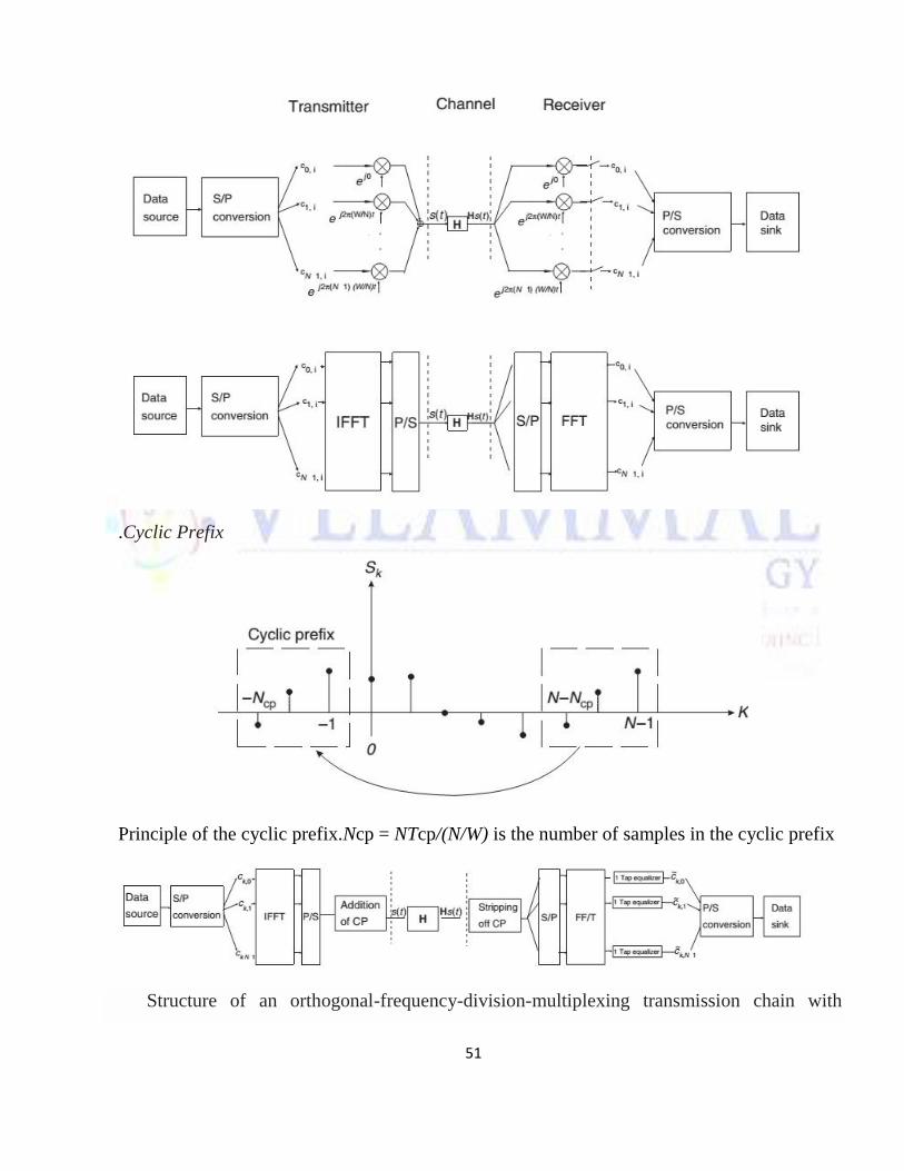
Implementation of Transceivers
Transceiver structures for orthogonal frequency division multiplexing in purely analog
technology, and using inverse fast Fourier transformation
51
.Cyclic Prefix
Principle of the cyclic prefix.Ncp = NTcp/(N/W) is the number of samples in the cyclic prefix
Structure of an orthogonal-frequency-division-multiplexing transmission chain with
52
cyclic prefix and one-tap equalization.
UNIT IV MULTIPATH MITIGATION TECHNIQUES
PART-A
1. State the principle of diversity.(June 2013) (Dec 2013)
There are many categories of diversity implementations. Diversity is a way to increase the
bit error rate by changing the channel statistics. It assures that the signal to noise ratio is
less when increasing the bit error rate.
2. What is Equalization? (Dec 2013)
Generally equalization is a technique which is used to increase the received signal quality
and link performance. This compensates for inter symbol interference created by
multipath within time dispersive channels.
3. Compare macro and micro diversity. (Dec 2014)
53
There are many categories of diversity implementations. Diversity is a way to increase the
bit error rate by changing the channel statistics. It assures that the signal to noise ratio is
less when increasing the bit error rate.
4. What are the applications of non linear equalizers? (June 2014)
The fundamental concept of this type of equalizer is that once an information system has
been detected and decided upon, the IS! which it induces on future symbols can be
estimated and subtracted out before detection of subsequent symbols.
5. List the advantages of digital modulation techniques.
Greater noise immunity, robustness to channel impairments, easier multiplexing of
various forms of information, Greater security
6. State the significance of linear and decision feedback equalizer.
If the analog signal is not used in the feedback path to adapt the equalizer then it is
referred as linear equalization.
7. Assume four branch diversity is used, where each branch receives an independent
Rayleigh fading signal. If the average SNR is 20 dB, determine the probability that the
8NR will drop below 10 dB. Compare this. with the case of a single receiver without
diversity.
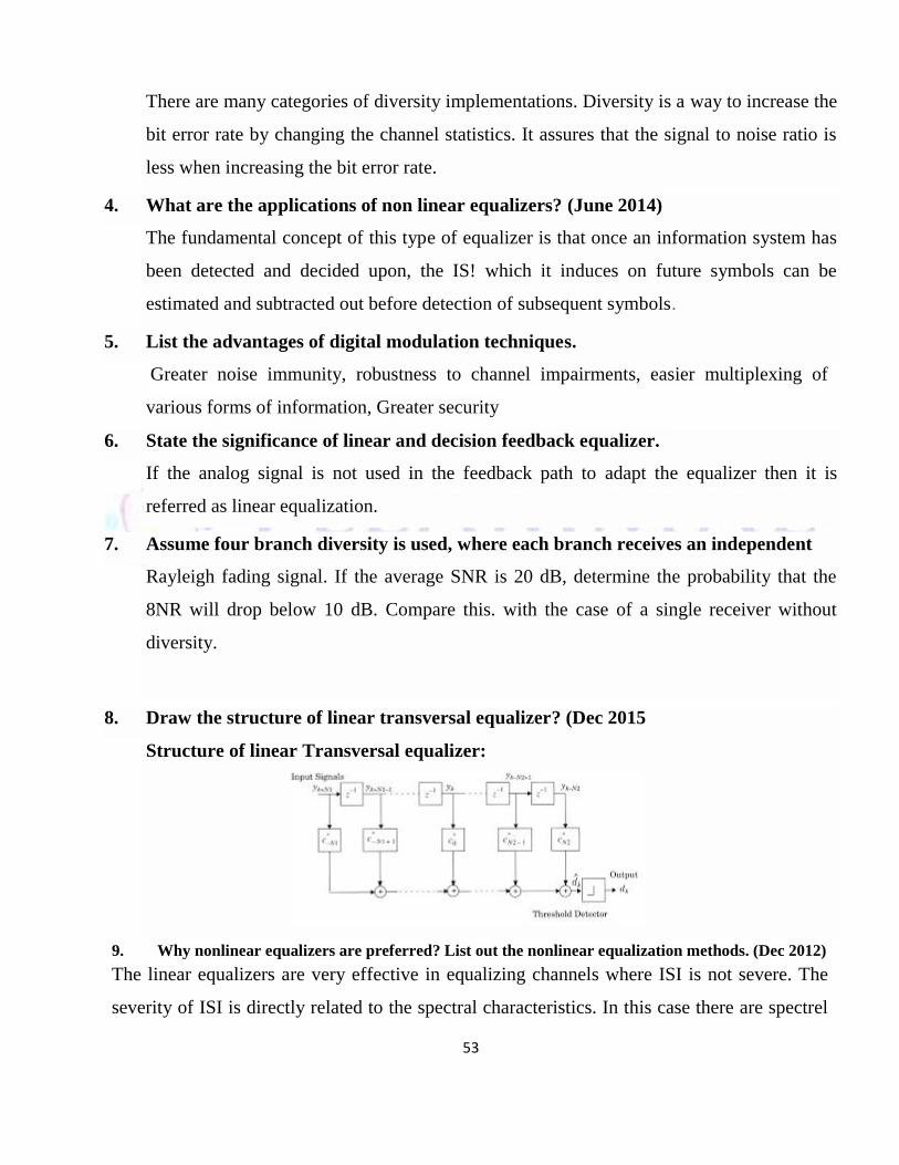
8. Draw the structure of linear transversal equalizer? (Dec 2015
Structure of linear Transversal equalizer:
9. Why nonlinear equalizers are preferred? List out the nonlinear equalization methods. (Dec 2012)
The linear equalizers are very effective in equalizing channels where ISI is not severe. The
severity of ISI is directly related to the spectral characteristics. In this case there are spectrel
54
nulls in the transfer function of the effective channel, the additive noise at the receiver input
will be dramatically enhanced by the linear equalizer. To overcome this problem, non linear
equalizers can be used.
Decision feedback equalization (DFE), Maximum likelihood symbol detection and
Maximum likelihood sequence estimation (MLSE) are the nonlinear equalization methods
used.
10. What is the need for diversity schemes?(May 2012)
To increase signal to noise ratio, For error free digital transmission, To degrade the bit error
probability.
Part –B
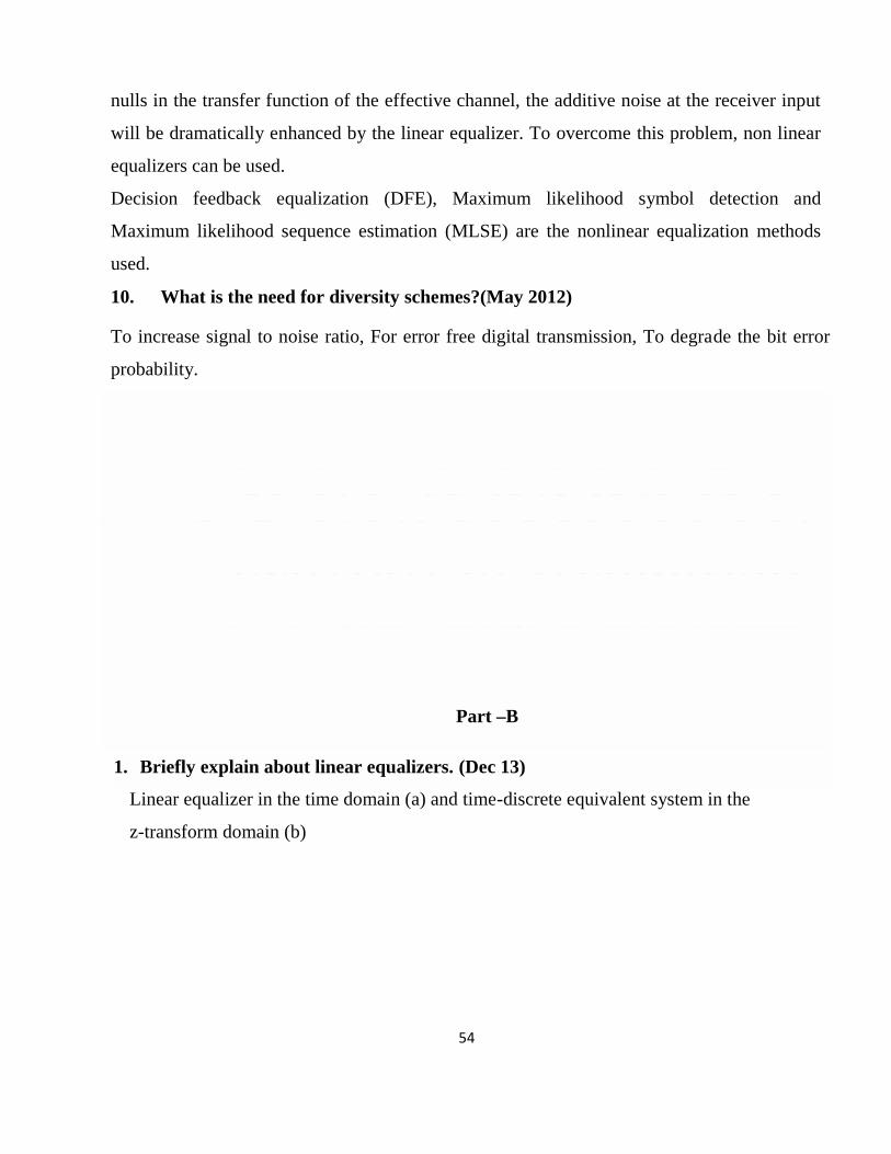
1. Briefly explain about linear equalizers. (Dec 13)
Linear equalizer in the time domain (a) and time-discrete equivalent system in the
z-transform domain (b)
55
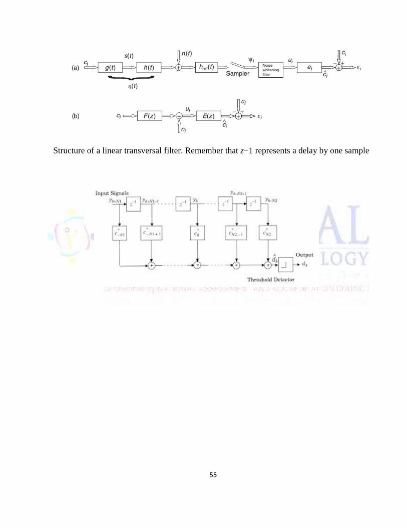
Structure of a linear transversal filter. Remember that z−1 represents a delay by one sample
56
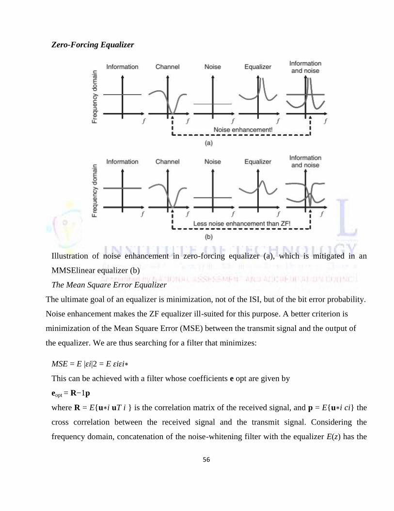
Zero-Forcing Equalizer
Illustration of noise enhancement in zero-forcing equalizer (a), which is mitigated in an
MMSElinear equalizer (b)
The Mean Square Error Equalizer
The ultimate goal of an equalizer is minimization, not of the ISI, but of the bit error probability.
Noise enhancement makes the ZF equalizer ill-suited for this purpose. A better criterion is
minimization of the Mean Square Error (MSE) between the transmit signal and the output of
the equalizer. We are thus searching for a filter that minimizes:
MSE = E |εi|2 = E εiεi∗This can be achieved with a filter whose coefficients e opt are given by
eopt = R−1p
where R = E{u∗i uT i } is the correlation matrix of the received signal, and p = E{u∗i ci} the
cross correlation between the received signal and the transmit signal. Considering the
frequency domain, concatenation of the noise-whitening filter with the equalizer E(z) has the
57
transfer function: E(z) ˜ = 1/E(z) + N0/σ2s which is the transfer function of the Wiener filter.
Comparison shows that the noise power of an MMSE equalizer is smaller than that of a ZF
equalizer
2. Explain about DFE and MLSE equalizer. (Dec 13)
A decision feedback equalizer (DFE) has a simple underlying premise: once we have
detected a bit correctly, we can use this knowledge in conjunction with knowledge of the
channel impulse response to compute the ISI caused by this bit. In other words, we determine
the effect this bit will have on subsequent samples of the receive signal. The ISI caused by
each bit can then be
subtracted from these later samples. The block diagram of a DFE is shown. The DFE consists
of a forward filter with transfer function E(z), which is a conventional linear equalizer, as
well as a feedbackfilter with transfer function D(z). As soon as the RX has decided on a
received symbol, its impact on all future samples (postcursorISI ) can be computed, and (via
the feedback) subtracted from the received signal. A key point is the fact that the ISI is
computed based on the signal after the hard decision; this eliminates additive noise from the
feedback signal. Therefore, a DFE results in a smaller error probability than a linear
equalizer. One possible source of problems is error propagation. If the RX decides
incorrectly for one bit, then the computed postcursor ISI is also erroneous, so that later\ signal
samples arriving at the decision device are even more afflicted by ISI than the unequalized
samples. This leads to a vicious cycle of wrong decisions and wrong subtraction of
postcursors. Error propagation does not usually play a role when the BER is small. Note,
however, that small error rates are often achieved via coding. It may therefore be necessary to
decode the bits, re-encode them (such that the signal becomes a noise-free version of the
received signal), and use this new signal in the feedback from the DFE.
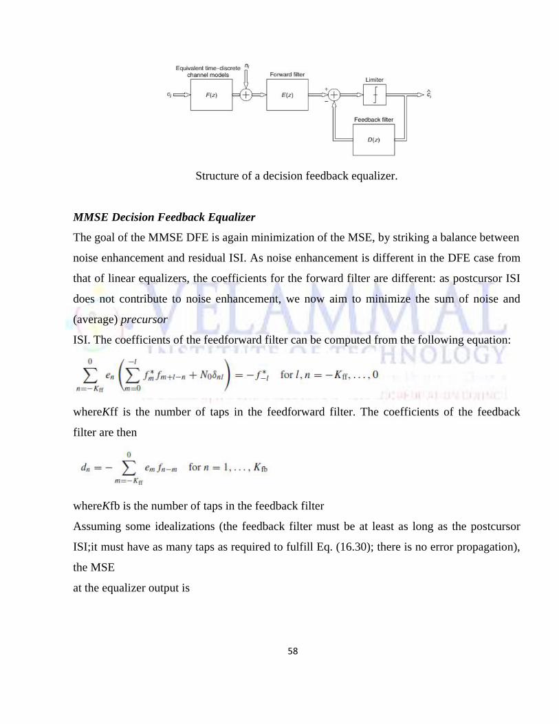
58
Structure of a decision feedback equalizer.
MMSE Decision Feedback Equalizer
The goal of the MMSE DFE is again minimization of the MSE, by striking a balance between
noise enhancement and residual ISI. As noise enhancement is different in the DFE case from
that of linear equalizers, the coefficients for the forward filter are different: as postcursor ISI
does not contribute to noise enhancement, we now aim to minimize the sum of noise and
(average) precursor
ISI. The coefficients of the feedforward filter can be computed from the following equation:
whereKff is the number of taps in the feedforward filter. The coefficients of the feedback
filter are then
whereKfb is the number of taps in the feedback filter
Assuming some idealizations (the feedback filter must be at least as long as the postcursor
ISI;it must have as many taps as required to fulfill Eq. (16.30); there is no error propagation),
the MSE
at the equalizer output is
59
3. Explain diversity techniques to combat small scale fading (June 2013)
Methods that can be used to combat small-scale fading, which are therefore called
“microdiversity.” The five most common methods are as follows:
Spatial diversity: several antenna elements separated in space.
MS in cellular and cordless systems: it is a standard assumption that waves are incident from
all directions at the MS. Thus, points of constructive and destructive interference of Multi
Path Components (MPCs) – i.e., points where we have high and low received power,
respectively – are spaced approximately λ/4 apart. This is therefore the distance that is
required for decorrelation of received signals. This intuitive insight agrees very well with the
results from the exact mathematical derivation (Eq. (13.4), with f2 − f1 = 0), decorrelation,
defined as ρ = 0.5, occurs at an antenna separation of λ/4. The above considerations imply
that the minimum distance for antenna elements in GSM (at 900 MHz) is about 8 cm, and for
various cordless and cellular systems at the 1,800-MHz band it is about 4 cm. For Wireless
Local Area Networks (WLANs) (at 2.4 and 5 GHz), the distances are even smaller. It is thus
clearly possible to place two antennas on an MS of a cellular system.
BS in cordless systems and WLANs: in a first approximation, the angular distribution of
incident radiation at indoor BSs is also uniform – i.e., radiation is incident with equal strength
from all directions. Therefore, the same rules apply as for MSs.
BSs in cellular systems: for a cellular BS, the assumption of uniform directions of incidence is
no longer valid. Interacting Objects (IOs) are typically concentrated around the MS. Since all
waves are incident essentially from one direction, the correlation
Temporal diversity: transmission of the transmit signal at different times.
Temporal diversity can be realized in different ways: 1. Repetition coding: this is the simplest
form. The signal is repeated several times, where the repetition intervals are long enough to
60
achieve decorrelation. This obviously achieves diversity, but is also highly bandwidth
inefficient. Spectral efficiency decreases by a factor that is equal to the number of repetitions.
2. Automatic Repeat reQuest( ARQ): here, the RX sends a message to the TX to indicate
whether it received the data with sufficient quality. If this is not the case, then the
transmission is repeated (after a wait period that achieves decorrelation). The spectral
efficiency of ARQ is better than that of repetition coding, since it requires multiple
transmissions only when the first transmission occurs in a bad fading state, while for
repetition coding, retransmissions occur always. On the downside, ARQ requires a feedback
channel.
3. Combination of interleaving and coding: a more advanced version of repetition coding is
forward error correction coding with interleaving. The different symbols of a codeword are
transmitted at different times, which increase the probability that at least some of them arrive
with a good SNR. The transmitted codeword can then be reconstructed.
Frequency diversity: transmission of the signal on different frequencies.
This spreading can be done by different methods: • Compressing the information in time: –
i.e., sending short bursts that each occupy a large bandwidth – TDMA
• Code Division Multiple Access (CDMA)
• Multicarrier CDMA and coded orthogonal frequency division multiplexing
• Frequency hopping in conjunction with coding: different parts of a codeword are
transmitted on different carrier frequencies
Angular diversity: multiple antennas (with or without spatial separation) with different
antenna patterns.
Polarization diversity: multiple antennas with different polarizations (e.g., vertical and
horizontal).
Horizontally and vertically polarized MPCs propagate differently in a wireless channel, as the
reflection and diffraction processes depend on polarization. Even if the transmit antenna only
sends signals with a single polarization, the propagation effects in the channel lead to
depolarization so that both polarizations arrive at the RX. The fading of signals with different
polarizations is statistically independent. Thus, receiving both polarizations using a dual-
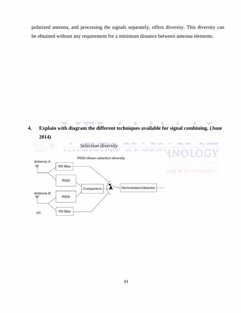
61
polarized antenna, and processing the signals separately, offers diversity. This diversity can
be obtained without any requirement for a minimum distance between antenna elements.
4. Explain with diagram the different techniques available for signal combining. (June
2014)
Selection diversity
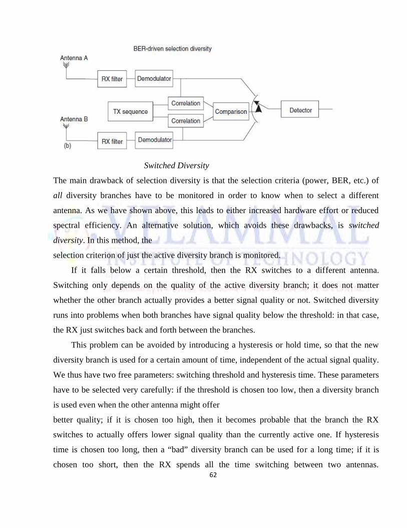
62
Switched Diversity
The main drawback of selection diversity is that the selection criteria (power, BER, etc.) of
all diversity branches have to be monitored in order to know when to select a different
antenna. As we have shown above, this leads to either increased hardware effort or reduced
spectral efficiency. An alternative solution, which avoids these drawbacks, is switched
diversity. In this method, the
selection criterion of just the active diversity branch is monitored.
If it falls below a certain threshold, then the RX switches to a different antenna.
Switching only depends on the quality of the active diversity branch; it does not matter
whether the other branch actually provides a better signal quality or not. Switched diversity
runs into problems when both branches have signal quality below the threshold: in that case,
the RX just switches back and forth between the branches.
This problem can be avoided by introducing a hysteresis or hold time, so that the new
diversity branch is used for a certain amount of time, independent of the actual signal quality.
We thus have two free parameters: switching threshold and hysteresis time. These parameters
have to be selected very carefully: if the threshold is chosen too low, then a diversity branch
is used even when the other antenna might offer
better quality; if it is chosen too high, then it becomes probable that the branch the RX
switches to actually offers lower signal quality than the currently active one. If hysteresis
time is chosen too long, then a “bad” diversity branch can be used for a long time; if it is
chosen too short, then the RX spends all the time switching between two antennas.
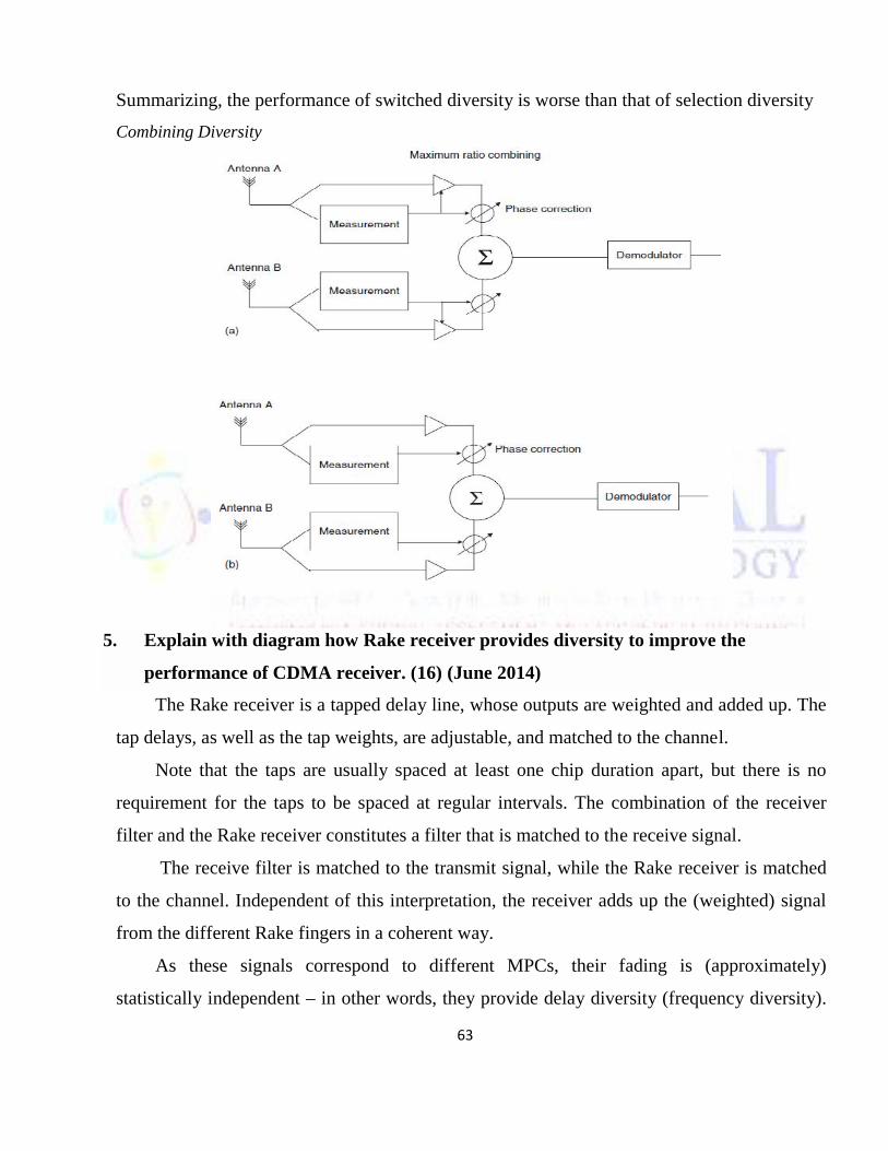
63
Summarizing, the performance of switched diversity is worse than that of selection diversity
Combining Diversity
5. Explain with diagram how Rake receiver provides diversity to improve the
performance of CDMA receiver. (16) (June 2014)
The Rake receiver is a tapped delay line, whose outputs are weighted and added up. The
tap delays, as well as the tap weights, are adjustable, and matched to the channel.
Note that the taps are usually spaced at least one chip duration apart, but there is no
requirement for the taps to be spaced at regular intervals. The combination of the receiver
filter and the Rake receiver constitutes a filter that is matched to the receive signal.
The receive filter is matched to the transmit signal, while the Rake receiver is matched
to the channel. Independent of this interpretation, the receiver adds up the (weighted) signal
from the different Rake fingers in a coherent way.
As these signals correspond to different MPCs, their fading is (approximately)
statistically independent – in other words, they provide delay diversity (frequency diversity).
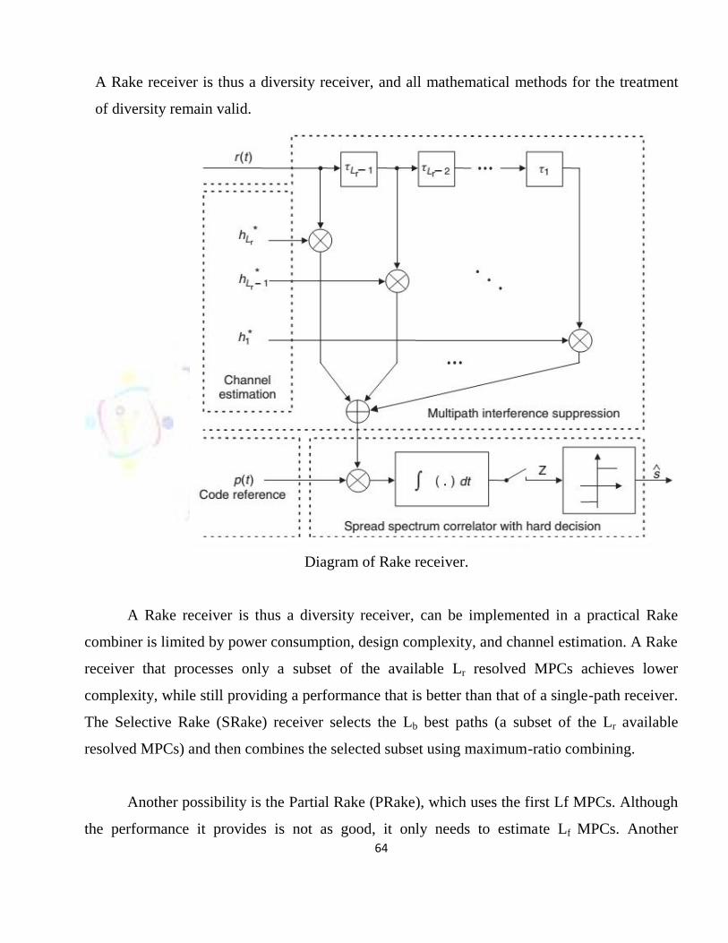
64
A Rake receiver is thus a diversity receiver, and all mathematical methods for the treatment
of diversity remain valid.
Diagram of Rake receiver.
A Rake receiver is thus a diversity receiver, can be implemented in a practical Rake
combiner is limited by power consumption, design complexity, and channel estimation. A Rake
receiver that processes only a subset of the available Lr resolved MPCs achieves lower
complexity, while still providing a performance that is better than that of a single-path receiver.
The Selective Rake (SRake) receiver selects the Lb best paths (a subset of the Lr available
resolved MPCs) and then combines the selected subset using maximum-ratio combining.
Another possibility is the Partial Rake (PRake), which uses the first Lf MPCs. Although
the performance it provides is not as good, it only needs to estimate Lf MPCs. Another
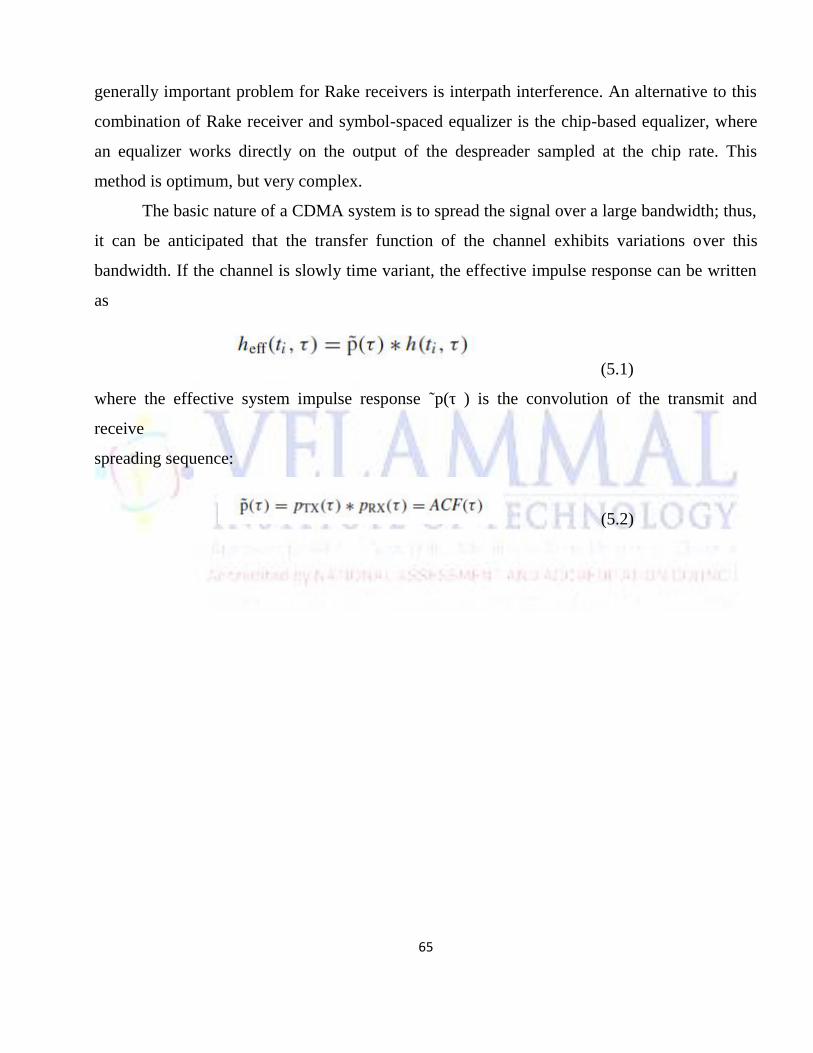
65
generally important problem for Rake receivers is interpath interference. An alternative to this
combination of Rake receiver and symbol-spaced equalizer is the chip-based equalizer, where
an equalizer works directly on the output of the despreader sampled at the chip rate. This
method is optimum, but very complex.
The basic nature of a CDMA system is to spread the signal over a large bandwidth; thus,
it can be anticipated that the transfer function of the channel exhibits variations over this
bandwidth. If the channel is slowly time variant, the effective impulse response can be written
as
(5.1)
where the effective system impulse response ˜p(τ ) is the convolution of the transmit and
receive
spreading sequence:
(5.2)
66
UNIT V MULTIPLE ANTENNA TECHNIQUES
PART-A
1. List the different types of channel coding techniques. (Dec 2014)
Repetition coding, Automatic repeat request.
2. What is frequency hopped multiple access?(June 2014)
In this type of method, at the same time, all the people can send the signals. These users
are differ in the frequency of operation.
3. Write about MMSE decision feedback equalizer. (May 2015)
The fundamental concept of this type of equalizer is that once an information system has
been detected and decided upon, the ISI which it induces on future symbols can be
estimated and subtracted out before detection of subsequent symbols.
4. Characterize the effects of multipath propagation on code division multiple
access.(May 2015)
Reflection - occurs when signal encounters a surface that is large relative to the
wavelength of the signal. Diffraction - occurs at the edge of an impenetrable body that is
large compared to
wavelength of radio wave.
5. What do you mean by transmit diversity? (May 2015)
There are many transmit antennas in the transmit diversity. The transmit power is divided
among these antennas. The systems need transmit diversity when it holds more.
6. Define coding gain. (MAY/JUNE 2016)
Coding is the embedding of signal constellation points in a higher dimensional signaling
space. The theory of coding says that it holds for temporally constant and temporally
varying channels.
7. Define Spatial multiplexing.
Capacity gain at no additional power or bandwidth consumption obtained through the use
of multiple antennas at both sides of a wireless radio link.
67
8. Define Diversity gain.
Improvement in link reliability obtained by transmitting the same data on independently
fading branches.
9. Define Transmit diversity. (Dec 2015)
Transmit diversity is radio communication using signals that originate from two or more
independent sources that have been modulated with identical information-bearing signals
and that may vary in their transmission characteristics at any given instant.
10. Define Receiver diversity.
Receive diversity improves the bit error rate (BER) performance. In this post, let us try to
understand the BER improvement with receive diversity.
11. What is antenna diversity(space diversity). ? (Dec 2015)
Conventional wireless systems consist of an elevated base station antenna and a mobile
antenna close to the ground .The existence of direct path between the transmitter &
receiver is not guaranteed and the possibility of a number of scatterers is large from this
JAKES deduced that the signal received from spatially separated antennas on the mobile
would have essentially uncorrelated envelopes for antenna separations of one half
wavelength or more.
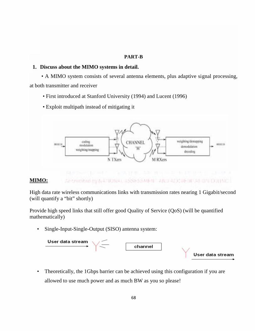
68
PART-B
1. Discuss about the MIMO systems in detail.
• A MIMO system consists of several antenna elements, plus adaptive signal processing,
at both transmitter and receiver
• First introduced at Stanford University (1994) and Lucent (1996)
• Exploit multipath instead of mitigating it
MIMO:
High data rate wireless communications links with transmission rates nearing 1 Gigabit/second(will quantify a “bit” shortly)
Provide high speed links that still offer good Quality of Service (QoS) (will be quantifiedmathematically)
• Single-Input-Single-Output (SISO) antenna system:
• Theoretically, the 1Gbps barrier can be achieved using this configuration if you are
allowed to use much power and as much BW as you so please!
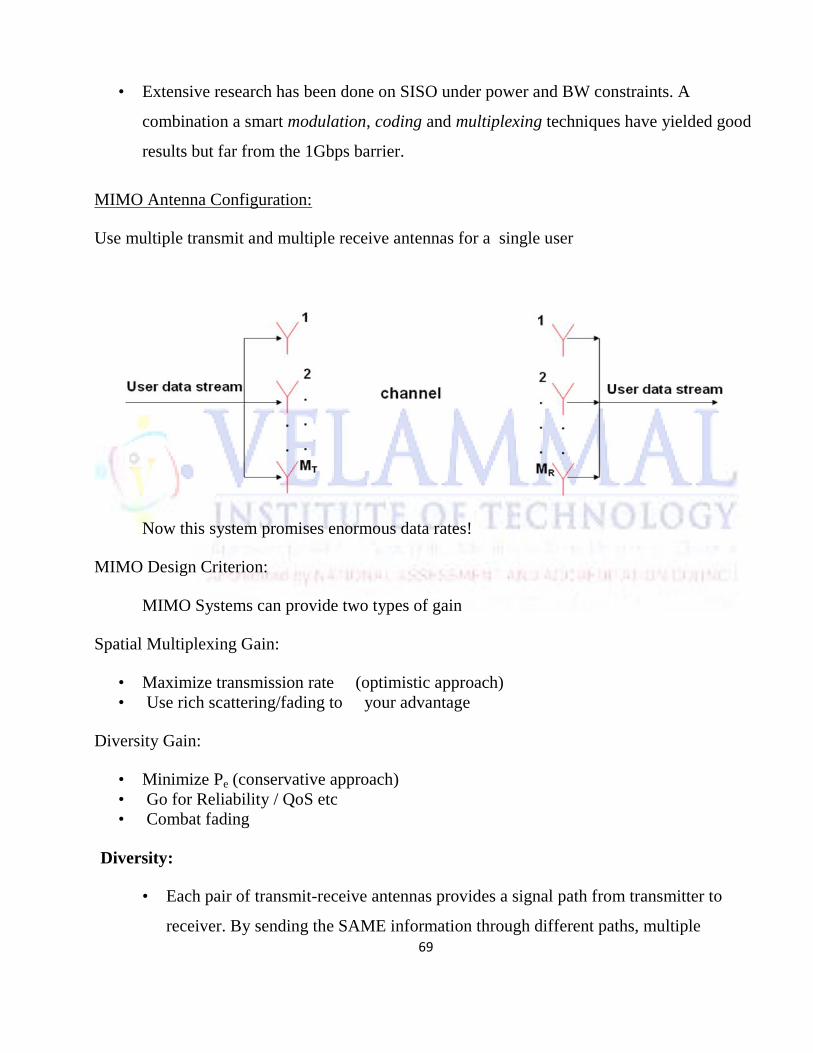
69
• Extensive research has been done on SISO under power and BW constraints. A
combination a smart modulation, coding and multiplexing techniques have yielded good
results but far from the 1Gbps barrier.
MIMO Antenna Configuration:
Use multiple transmit and multiple receive antennas for a single user
Now this system promises enormous data rates!
MIMO Design Criterion:
MIMO Systems can provide two types of gain
Spatial Multiplexing Gain:
• Maximize transmission rate (optimistic approach)• Use rich scattering/fading to your advantage
Diversity Gain:
• Minimize Pe (conservative approach)• Go for Reliability / QoS etc• Combat fading
Diversity:
• Each pair of transmit-receive antennas provides a signal path from transmitter to
receiver. By sending the SAME information through different paths, multiple
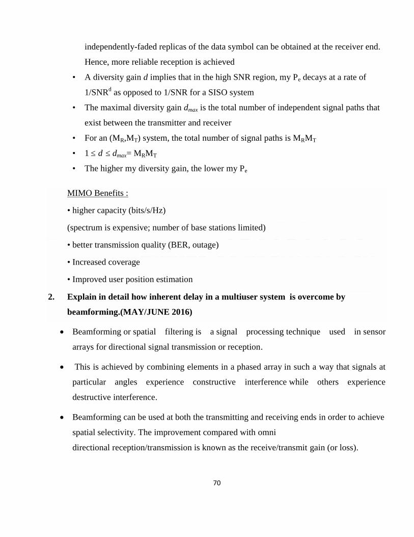
70
independently-faded replicas of the data symbol can be obtained at the receiver end.
Hence, more reliable reception is achieved
• A diversity gain d implies that in the high SNR region, my Pe decays at a rate of
1/SNRd as opposed to 1/SNR for a SISO system
• The maximal diversity gain dmax is the total number of independent signal paths that
exist between the transmitter and receiver
• For an (MR,MT) system, the total number of signal paths is MRMT
• 1 ≤ d ≤ dmax= MRMT
• The higher my diversity gain, the lower my Pe
MIMO Benefits :
• higher capacity (bits/s/Hz)
(spectrum is expensive; number of base stations limited)
• better transmission quality (BER, outage)
• Increased coverage
• Improved user position estimation
2. Explain in detail how inherent delay in a multiuser system is overcome by
beamforming.(MAY/JUNE 2016)
Beamforming or spatial filtering is a signal processing technique used in sensor
arrays for directional signal transmission or reception.
This is achieved by combining elements in a phased array in such a way that signals at
particular angles experience constructive interference while others experience
destructive interference.
Beamforming can be used at both the transmitting and receiving ends in order to achieve
spatial selectivity. The improvement compared with omni
directional reception/transmission is known as the receive/transmit gain (or loss).
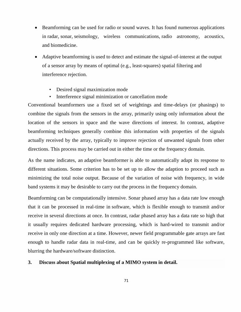
71
Beamforming can be used for radio or sound waves. It has found numerous applications
in radar, sonar, seismology, wireless communications, radio astronomy, acoustics,
and biomedicine.
Adaptive beamforming is used to detect and estimate the signal-of-interest at the output
of a sensor array by means of optimal (e.g., least-squares) spatial filtering and
interference rejection.
• Desired signal maximization mode• Interference signal minimization or cancellation mode
Conventional beamformers use a fixed set of weightings and time-delays (or phasings) to
combine the signals from the sensors in the array, primarily using only information about the
location of the sensors in space and the wave directions of interest. In contrast, adaptive
beamforming techniques generally combine this information with properties of the signals
actually received by the array, typically to improve rejection of unwanted signals from other
directions. This process may be carried out in either the time or the frequency domain.
As the name indicates, an adaptive beamformer is able to automatically adapt its response to
different situations. Some criterion has to be set up to allow the adaption to proceed such as
minimizing the total noise output. Because of the variation of noise with frequency, in wide
band systems it may be desirable to carry out the process in the frequency domain.
Beamforming can be computationally intensive. Sonar phased array has a data rate low enough
that it can be processed in real-time in software, which is flexible enough to transmit and/or
receive in several directions at once. In contrast, radar phased array has a data rate so high that
it usually requires dedicated hardware processing, which is hard-wired to transmit and/or
receive in only one direction at a time. However, newer field programmable gate arrays are fast
enough to handle radar data in real-time, and can be quickly re-programmed like software,
blurring the hardware/software distinction.
3. Discuss about Spatial multiplexing of a MIMO system in detail.
72
We send multiple signals, the receiver learns the channel matrix and inverts it to
separate the data.
MIMO spatial multiplexing in Line-of-sight
The system is near rank one (non invertible)
Spatial multiplexing requires multipath to work
Spatial Multiplexing:
y = Hs + n y’ = Ds’ + n’ (through SVD on H)
where D is a diagonal matrix that contains the eigenvalues of HHH Viewing the MIMO
received vector in a different but equivalent way,
CEP = log 2 [IM + (P/MT)DDH] = log 2 [1 + (P/MT)גi] b/s/Hz
Equivalent form tells us that an (MT,MR) MIMO channel opens up
m = min (MT,MR) independent SISO channels between the transmitter and the receiver
So, intuitively, I can send a maximum of m different information symbols over the channel
at any given time.
Practical System:
73
rs : number of different symbols N transmitted in T symbol periods
rs = N/T
Spectral efficiency = (R*rc info bits/symbol)(rs)(Rs symbols/sec)/w
= Rrcrs bits/s/Hz assuming Rs = w
rs is the parameter that we are concerned about: 0 ≤ rs ≤ MT
** If rs = MT, we are in spatial multiplexing mode (max transmission rate)
**If rs ≤ 1, we are in diversity mode
• MIMO Systems are getting us closer to the 1Gbps landmark (aspiration 1)
• At the same time, they provide reliable communications (aspiration 2)
4. Discuss about transmitter diversity, receiver diversity in detail.
By combining signals from different at the RX, the total quality of the signal is improved.
Signals selected from the multiple diversity branches by
1. Selection diversity, where the “best” signal copy is selected and processed (demodulated and
decoded), while all other copies are discarded. There are different criteria for what constitutes
the “best” signal.
2. Combining diversity, where all copies of the signal are combined (before or after the
demodulator), and the combined signal is decoded. Again, there are different algorithms for
combination of the signals.
Combining diversity leads to better performance, as all available information is exploited.
We also have to keep in mind that the gain of multiple antennas is due to two effects:
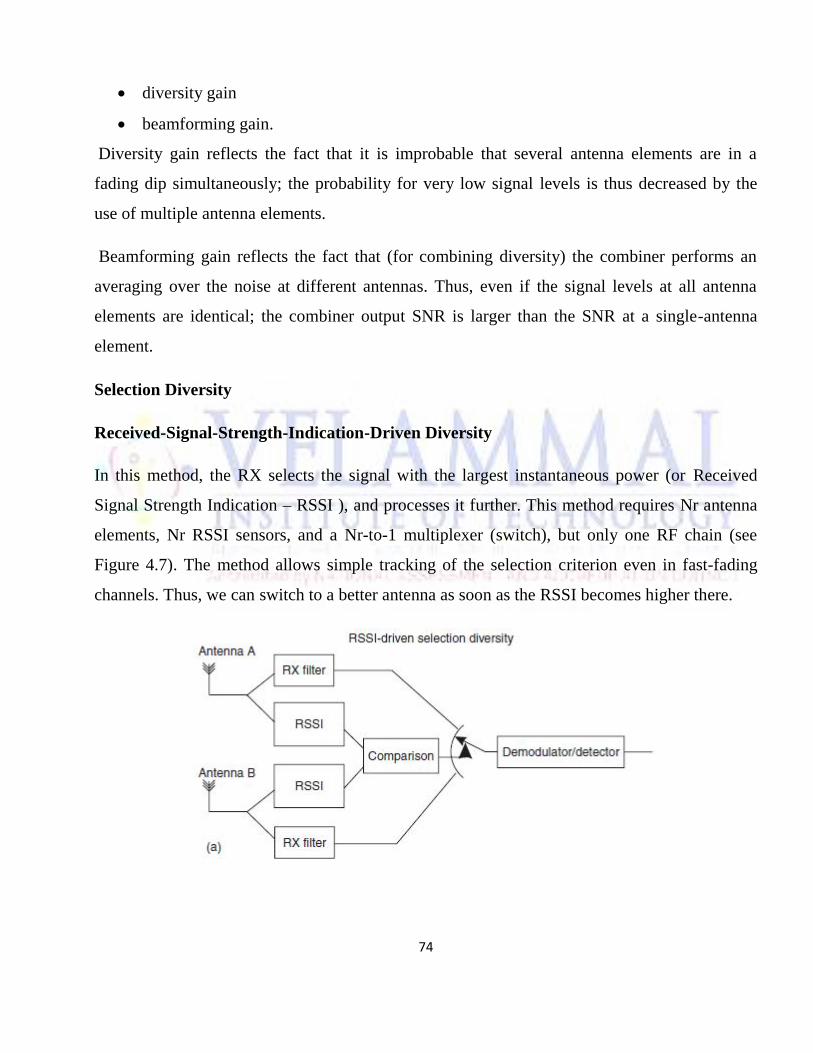
74
diversity gain
beamforming gain.
Diversity gain reflects the fact that it is improbable that several antenna elements are in a
fading dip simultaneously; the probability for very low signal levels is thus decreased by the
use of multiple antenna elements.
Beamforming gain reflects the fact that (for combining diversity) the combiner performs an
averaging over the noise at different antennas. Thus, even if the signal levels at all antenna
elements are identical; the combiner output SNR is larger than the SNR at a single-antenna
element.
Selection Diversity
Received-Signal-Strength-Indication-Driven Diversity
In this method, the RX selects the signal with the largest instantaneous power (or Received
Signal Strength Indication – RSSI ), and processes it further. This method requires Nr antenna
elements, Nr RSSI sensors, and a Nr-to-1 multiplexer (switch), but only one RF chain (see
Figure 4.7). The method allows simple tracking of the selection criterion even in fast-fading
channels. Thus, we can switch to a better antenna as soon as the RSSI becomes higher there.
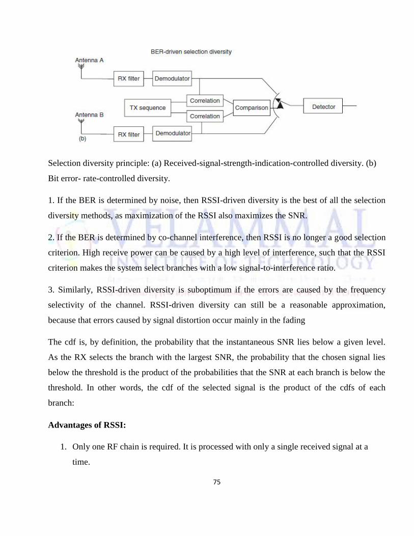
75
Selection diversity principle: (a) Received-signal-strength-indication-controlled diversity. (b)
Bit error- rate-controlled diversity.
1. If the BER is determined by noise, then RSSI-driven diversity is the best of all the selection
diversity methods, as maximization of the RSSI also maximizes the SNR.
2. If the BER is determined by co-channel interference, then RSSI is no longer a good selection
criterion. High receive power can be caused by a high level of interference, such that the RSSI
criterion makes the system select branches with a low signal-to-interference ratio.
3. Similarly, RSSI-driven diversity is suboptimum if the errors are caused by the frequency
selectivity of the channel. RSSI-driven diversity can still be a reasonable approximation,
because that errors caused by signal distortion occur mainly in the fading
The cdf is, by definition, the probability that the instantaneous SNR lies below a given level.
As the RX selects the branch with the largest SNR, the probability that the chosen signal lies
below the threshold is the product of the probabilities that the SNR at each branch is below the
threshold. In other words, the cdf of the selected signal is the product of the cdfs of each
branch:
Advantages of RSSI:
1. Only one RF chain is required. It is processed with only a single received signal at a
time.
76
2. Easy to implement.
Disadvantage of RSSI:
1. It wastes signal energy by discarding (Nr -1) copies of received signal.
2. It is not an optimum method.
Bit-Error-Rate-Driven Diversity
For BER-driven diversity, we first transmit a training sequence – i.e., a bit sequence that is
known at the RX. The RX then demodulates the signal from each receive antenna element and
compares it with the transmit signal. The antenna whose associated signal results in the
smallest BER is judged to be the “best,” and used for the subsequent reception of data signals.
A similar approach is the use of the mean square error of the “soft-decision” demodulated
signal, or the correlation between transmit and receive signal.
BER-driven diversity has several drawbacks:
1. The RX needs either Nr RF chains or demodulators (which makes the RX more complex), or
the training sequence has to be repeated Nr times (which decreases spectral efficiency), so that
the signal at all antenna elements can be evaluated.
2. If the RX has only one demodulator, then it is not possible to continuously monitor the
selection criterion (i.e., the BER) of all diversity branches. This is especially critical if the
channel changes quickly.
3. Since the duration of the training sequence is finite, the selection criterion – i.e., bit error
probability – cannot be determined exactly. The variance of the BER around its true mean
decreases as the duration of the training sequence increases.
Disadvantage of BER
1. More number of RXs are needed, which makes the RX more complex.
77
2. The training sequence has to be repeated Nr times, which decreases spectral efficiency.
3. If the channel changes quickly, more than one demodulators are required.
4. Duration of training sequence increases, BER decreases. So trade off between duration
of training sequence and BER is maintained.
5. Diversity branches are monitored all the times, so hardware effort increases, spectral
efficiency is reduced.
Switched Diversity
The main drawback of selection diversity is that the selection criteria (power, BER, etc.) of all
diversity branches have to be monitored in order to know when to select a different antenna. As
we have shown above, this leads to either increased hardware effort or reduced spectral
efficiency. An alternative solution, which avoids these drawbacks, is switched diversity. In this
method, the selection criterion of just the active diversity branch is monitored. If it falls below
a certain threshold, then the RX switches to a different antenna.
Switching only depends on the quality of the active diversity branch; it does not matter whether
the other branch actually provides a better signal quality or not.
Switched diversity runs into problems when both branches have signal quality below the
threshold. This problem can be avoided by introducing a hysteresis or hold time, so that the
new diversity branch is used for a certain amount of time, independent of the actual signal
quality. We thus have two free parameters: switching threshold and hysteresis time. These
parameters have to be selected very carefully: if the threshold is chosen too low, then a
diversity branch is used even when the other antenna might offer better quality; if it is chosen
too high, then it becomes probable that the branch the RX switches to actually offers lower
signal quality than the currently active one. If hysteresis time is chosen too long, then a “bad”
diversity branch can be used for a long time; if it is chosen too short, then the RX spends all the
time switching between two antennas.
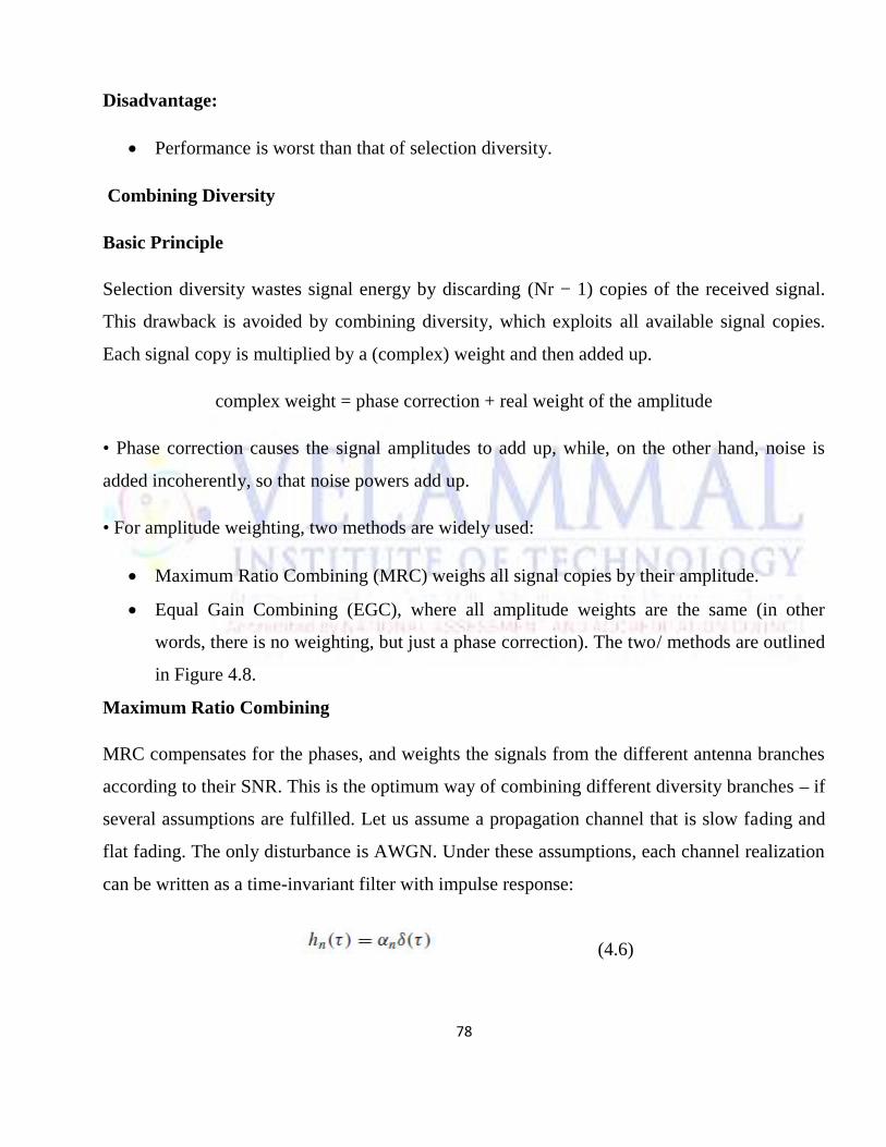
78
Disadvantage:
Performance is worst than that of selection diversity.
Combining Diversity
Basic Principle
Selection diversity wastes signal energy by discarding (Nr − 1) copies of the received signal.
This drawback is avoided by combining diversity, which exploits all available signal copies.
Each signal copy is multiplied by a (complex) weight and then added up.
complex weight = phase correction + real weight of the amplitude
• Phase correction causes the signal amplitudes to add up, while, on the other hand, noise is
added incoherently, so that noise powers add up.
• For amplitude weighting, two methods are widely used:
Maximum Ratio Combining (MRC) weighs all signal copies by their amplitude.
Equal Gain Combining (EGC), where all amplitude weights are the same (in other
words, there is no weighting, but just a phase correction). The two/ methods are outlined
in Figure 4.8.
Maximum Ratio Combining
MRC compensates for the phases, and weights the signals from the different antenna branches
according to their SNR. This is the optimum way of combining different diversity branches – if
several assumptions are fulfilled. Let us assume a propagation channel that is slow fading and
flat fading. The only disturbance is AWGN. Under these assumptions, each channel realization
can be written as a time-invariant filter with impulse response:
(4.6)
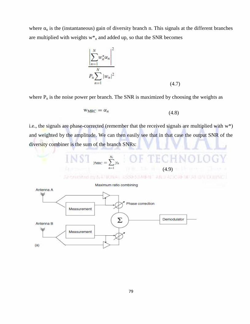
79
where αn is the (instantaneous) gain of diversity branch n. This signals at the different branches
are multiplied with weights w*n and added up, so that the SNR becomes
(4.7)
where Pn is the noise power per branch. The SNR is maximized by choosing the weights as
(4.8)
i.e., the signals are phase-corrected (remember that the received signals are multiplied with w*)
and weighted by the amplitude. We can then easily see that in that case the output SNR of the
diversity combiner is the sum of the branch SNRs:
(4.9)
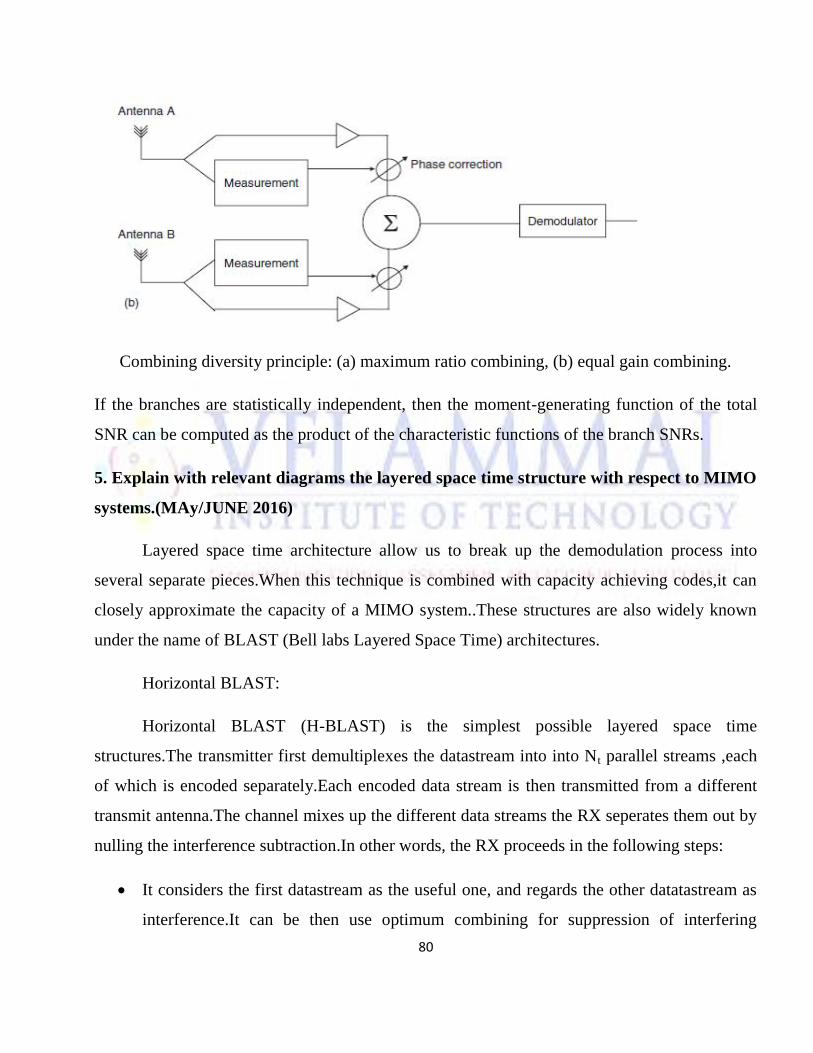
80
Combining diversity principle: (a) maximum ratio combining, (b) equal gain combining.
If the branches are statistically independent, then the moment-generating function of the total
SNR can be computed as the product of the characteristic functions of the branch SNRs.
5. Explain with relevant diagrams the layered space time structure with respect to MIMO
systems.(MAy/JUNE 2016)
Layered space time architecture allow us to break up the demodulation process into
several separate pieces.When this technique is combined with capacity achieving codes,it can
closely approximate the capacity of a MIMO system..These structures are also widely known
under the name of BLAST (Bell labs Layered Space Time) architectures.
Horizontal BLAST:
Horizontal BLAST (H-BLAST) is the simplest possible layered space time
structures.The transmitter first demultiplexes the datastream into into Nt parallel streams ,each
of which is encoded separately.Each encoded data stream is then transmitted from a different
transmit antenna.The channel mixes up the different data streams the RX seperates them out by
nulling the interference subtraction.In other words, the RX proceeds in the following steps:
It considers the first datastream as the useful one, and regards the other datatastream as
interference.It can be then use optimum combining for suppression of interfering
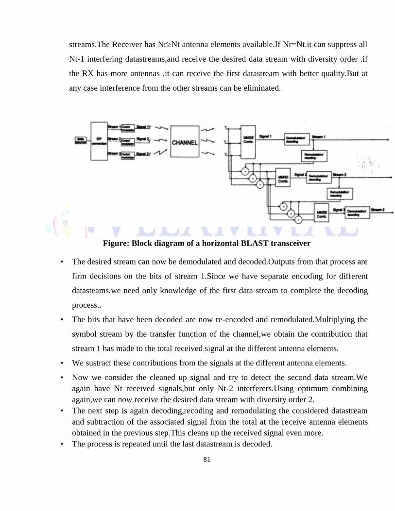
81
streams.The Receiver has Nr≥Nt antenna elements available.If Nr=Nt.it can suppress all
Nt-1 interfering datastreams,and receive the desired data stream with diversity order .if
the RX has more antennas ,it can receive the first datastream with better quality.But at
any case interference from the other streams can be eliminated.
Figure: Block diagram of a horizontal BLAST transceiver
• The desired stream can now be demodulated and decoded.Outputs from that process are
firm decisions on the bits of stream 1.Since we have separate encoding for different
datasteams,we need only knowledge of the first data stream to complete the decoding
process..
• The bits that have been decoded are now re-encoded and remodulated.Multiplying the
symbol stream by the transfer function of the channel,we obtain the contribution that
stream 1 has made to the total received signal at the different antenna elements.
• We sustract these contributions from the signals at the different antenna elements.
• Now we consider the cleaned up signal and try to detect the second data stream.Weagain have Nt received signals,but only Nt-2 interferers.Using optimum combiningagain,we can now receive the desired data stream with diversity order 2.
• The next step is again decoding,recoding and remodulating the considered datastreamand subtraction of the associated signal from the total at the receive antenna elementsobtained in the previous step.This cleans up the received signal even more.
• The process is repeated until the last datastream is decoded.
82
• Even with stream ordering,HBlast does not achieve channel capacity.However itssimplity still makes the scheme an attractive one
Question paper Code:51416
B.E/B.Tech DEGREE EXAMINATION, MAY/JUNE 2014
Seventh Semester
Electronics & Communication Engineering
EC 2401-WIRELESS COMMUNICATION
(Regulation 2008/2010)
Time: Three hours Maximum: 100 marks
PART A(10x2=20 marks)
1. What are the basic requirements for wireless services?
2. What is frequency hopped multiple access?
3. State the propagation effects in mobile radio.
4. Interpret link budget equation.
5. What are the main features of QPSK?
6. What are Rayleigh and Ricean fading?
7. Compare macro and micro diversity.
8. What are the applications of non linear equalizers?
9. Why QPSK is preferred for wireless communications?
10. List the advantages of third generation (3G) networks.
Part B-(5*16=80 marks)
11. (a) (i) Discuss about the technical challenges face by the wireless communication. (10)
83
(ii)What are the features of interference limited systems. (6)
Or
(b) What are the major differences between TDMA, FDMA and CDMA?(16)
12. (a) (i)Explain how signal propagates against free space attenuation and reflection. (8)
(ii)Discuss about the temporal channel variations in Fixed Wireless Systems. (8)
Or
(b) (i) Explain in detail two path model propagation mechanism. (8)
(ii)Explain different models for characterizing wide band channels. (8)
13. (a) Explain with neat diagram the QPSK based transmission and reception technique and
their significance in the wireless system. (16)
Or
(b)Explain with neat diagram, the principle of Gaussian Minimum shift Keying receiver
and mention how this is different from MSK. (16)
14. (a) (i)What is the need for diversity ?List different types of diversity. (6)
(ii)Explain with diagram, the different techniques available for signal combining.(10)
Or
(b)With neat block diagram explain how RAKE receiver provides diversity to improve
the performance of CDMA receiver (16)
15. (a)Describe the principle involved in Cellular Code-Division-Multiple-Access Systems.
(16)
Or
(b)Explain with necessary diagram, the operation of Orthoganal FrequencyDivide
Multiplexing transceiver. (16)
84
Question paper Code: 91419
B.E/B.Tech DEGREE EXAMINATION, NOVEMBER/DECEMBER 2014
Seventh Semester
Electronics & Communication Engineering
EC 2401-WIRELESS COMMUNICATION
(Regulation 2008/2010)
Time: Three hours Maximum: 100 marks
PART A(10x2=20 marks)
1. What are the different modules of a basic cellular system?
2. State advantages of CDMA over FDMA?
3. List the different types of propagation machanisms.
4. What are the different fading effects due to Doppler Spread?
5. State advantages of Offset-QPSK.
6. List the advantages of GMSK.
7. List the different types of channel coding techniques.
8. Differentiate between Macrodiversity and Microdiversity.
9. What are the effects of Multipath propagation on CDMA?
10. List some important features of 3G networks.
PART B(5x16=80 Marks)
11. (a) (i) With a block diagram of a basic cellular system, explain its various
85
functional modules and the method by which a call is routed. (10)
(ii) Explain in detail a handoff scenario at cell boundary (6)
Or
(b) (i) Explain the different types of multipath propagation in wireless
communication. (10)
(ii) With neat illustration, explain CDMA. (6)
12. (a) (i) Explain briefly on outdoor propagation models. (8)
(ii) Describe in detail Two Ray Rayleigh Fading Model. (8)
Or
(b) (i) Explain on path loss estimation techniques using path loss models.(8)
(ii) Describe on Ricean distribution.
13. (a) (i) Explain with neat constellation diagram the modulation technique ofQPSK. (8)
(ii) List the advantages and application of BPSK. (8)Or
(b) (i) Describe with a block diagram π/4 Quadrature Phase Shift Keying
and its advantages (8)
(ii) What is MSK? Explain its power spectral density. (8)
14. (a) (i) With a neat block diagram, explain the principle of Macrodiversity.(8)
(ii) Explain the operation an adaptive equalizer at the receiver side. (8)
Or
(b) (i) Explain with a block diagram Maximal ratio combiner. (8)
(ii) Describe on Polarization and Space Diversity. (8)
15. (a) Write short notes on the following :(i) Frequency Hopping and its advantages. (8)(ii)Orthogonal FDM (OFDM) (8)
86
Or
(b) Discuss in detail the 2G and 3G wireless network standards. Compare
the relative merits and demerits of both the standards (16)
Question Paper Code: 71467
B.E/B.TECH DEGREE OF EXAMINATION, APRIL/MAY 2015
Seventh Semester
Electronics and Communication Engineering
EC2401/EC71/10144 EC701-Wireless communication
(Regulation 2008/2010)
Time: Three hours Maximum:100marks
Answer ALL Questions
PART A – ( 10 *2=20 marks)
1. State the difference between small-scale fading and large scale fading?
2. Mention a few techniques used to expand the capacity of a cellular system?
3. Interpret Snell’s law?
4. List the properties of wideband channels?
5. Comment on the necessity of a Gaussian filter in GMSK?
6. List the advantages of digital modulation techniques?
7. What do you meant by transmit diversity?
8. Write about MMSK decision feedback equalizer?
9. Characteristics the effects of multipath propagation on code division multiple access?
10. What are the basic channels available in GSM?
87
PART B- ( 5*16=80 marks)
11. (a) (1) Elaborate about the factors which influence small scale fading. (8)
(2) Comment on the different types of services in detail. (8)
Or
(b) (1) Discuss about the construction and destructive interference in detail. (8)
(2) Give the details about the causes for Inter symbol Interference? How can
ISI be eliminated. (8)
12. ( a ) (1) Explain in brief the three propagation mechanisms which have impact
On Propagation in a mobile environment (8)
(2) Define Brewster angle .Calculate Brewster angle for a wave impinging
On a ground permittivity=4 (8)
Or
(b) In detail explain about channel classification. (16)
13 (a) (1) Explain the structure of Wireless Communication link in detail (6)
(2) Demonstrate the generation and detection and bit error probability of
QPSK scheme. (10)
Or
(b)(1)How MSK signals are generated? Explain in detail (8)
(2)Discuss in detail the demodulation techniques for Minimum Shift keying. (8)
14 (a) Write the short notes on
(1) Spatial diversity (4)(2) Temporal diversity (4)(3) Polarization diversity (4)(4) Macrodiversity (4)
Or
(b) (1)Explain in detail about linear equalizers (8)
(2)With suitable diagrams, explain channel coding and speech
codingTechniques. (8)
88
15.(a) Examine about the effects of multipath propagation on CDMA (16)
Or
(b) (1) Illustrate the block diagram of IS-95 Transmitter (8)
(2) Give a detailed description off OFDM Transceiver. (8)
Question paper Code: 51416
B.E/B.Tech DEGREE EXAMINATION, NOVEMBER/DECEMBER 2015
Seventh Semester
Electronics & Communication Engineering
EC 2401-WIRELESS COMMUNICATION
(Regulation 2008/2010)
Time: Three hours Maximum: 100 marks
PART A(10x2=20 marks)
1. Mention the operating frequency ranges for AMPS and ETACS systems.
2. Define mean excess delay and rms delay spread.
3. Define Co-channel Interference.
4. Define Coherence time.
5. What do you mean by Non-coherent Detection?
6. Draw the Constellation diagram of Binary Frequency Shift Keying system.
7. If a digital signal processing chip can perform one million multiplications per
second, determine the time required between each iteration for the following
adaptive equalizer algorithm LMS.
8. What is Transmit Diversity?
89
9. Draw the block diagram of a Direct Sequence Spread Spectrum Transmitter.
10. What is IS-95 Standard?
PART-B—(5*16=80marks)
11 (a) (1) With diagram explain Personal Access Communication system. (8)
(2) Briefly explain ETACS System. (8)
(or)
(b) (1) Explain some techniques intended to improve the coverage area and
Capacity of cellular system. (8)
(2) Analyze co-channel interference and adjacent channel interference
and suggest some measures to reduce them. (8)
12. (a) Derive the expressions for the total Electric field, Eror(d) and received
power at distance, Pr(d) using two – ray ground reflection model. (16)
(or)
(b) The fading characteristics of a CW carrier in an urban area to be
measured. The following assumptions are made :
I. The mobile receiver uses a simple vertical monopole.
II. Large-scale fading due to path loss is ignored.
III. The mobile has no line-of-sight path to the base station
IV. The pdf of the received signal follows a Rayleigh distribution
(1) Derive the ratio of the desired signal level to the rms signal
Level that maximizes the level crossing rate. Express your
Answer in dB. (5)
(2) Assuming the maximum velocity of the mobile is 50 km/hr,
and the carrier frequency is 900MHz, determine the
maximum number of times the signal envelope will fade below
the level found in (1) during a one minute test. (6)
(3) How long, on average, will each fade in (2) last? (5)
13. (a) Derive the expression for MSK signal as a special type of continuous
phase FSK signal. (16)
90
(or)
(b) Explain in detail about the Gaussian Minimum Shift keying (GMSK)
Transmission and Reception with necessary diagrams. (16)
14. (a) Explain in detail about Space diversity with necessary diagrams (16)
(or)
(b) Derive the LMS Algorithm for an Adaptive Equalizer. (16)
15. (a) Explain in detail about various spread spectrum multiple accesstechniques with neat block diagrams. (16)
(or)(b) Draw the basic arrangement of multitone OFDM transceiver and discuss
its overall operation. (16)
Question paper Code:91419
B.E/B.Tech DEGREE EXAMINATION, MAY/JUNE 2016
Fifth Semester
Information Technology
EC 6801-WIRELESS COMMUNICATION
(Regulations 2013)
Time: Three hours Maximum: 100 marks
PART A(10x2=20 marks
1. Calculate the Brewster Angle for wave impinging on ground having a permittivity ɛr=5.
2. Define coherence bandwidth.
3. What is soft hand off in mobile communication?
4. What is multiple access technique?
5. Why is MSK referred to as fast FSK?
6. What is windowing?
91
7. Define adaptive equalization?
8. What are the benefits of RAKE receiver?
9. What is MIMO system?
10. What is transmit diversity?
PART B(5x16=80 Marks)
11. (a) In free space pronagation describe how the signals are affected by reflection diffractionand scattering. (16)
Or
(b) Explain in detail the various parameters involved in mobile multipath channels. (16)
12. (a) Summarise the features of various multiple access technique used in wireless mobile
communication. State the advantages and disadvantages of each technique (16)
Or
(b) Explain in detail how to improve coverage and channel capacity in cellular systems (16)
13. (a) Explain in detail Offset QPSK and π/4-DQPSK linear digital modulation techniquesemployed in wireless communication. (16)
Or
(b) Explain in detail Gaussian Minimum Shift Keying(GMSK) transmission and receptionwith necessary diagrams.
(16)14. (a) Explain in detail about linear and non linear equalizer. (16)
Or
(b) Write short notes on : (16)
(i) Spatial Diversity(ii) Frequency Diversity(iii)Polarization Diversity(iv)Time Diversity
15. (a) (i) Explain in detail how inherent delay in a multiuser system is overcome by beamforming. (8)
(ii) Explain in detail spatial multiplexing of a MIMO system. (8)
92
Or
(b) Explain with relevant diagrams the layered space time structure with respect toMIMO systems. (16)
Question Paper code:51467
B.E/B.Tech.DEGREE EXAMINATION,MAY/JUNE 2016.
Seventh Semester
Electronics and Communication Engineerimg
EC2401/EC71/10144EC701-WIRELESS COMMUNIATION
(Regulations 2008/2010)
(Common to PTEC 2401-Wireless Communication for B.E (Part Time)
Sixth Semester-ECE-Regulations 2009)
Time:Three hours Maximum:100 marks
Answer ALL questions
PARTA-(10X2=20 marks)
1.Define frequency reuse.
2.State the operating principle of adhocnetworks.
93
3.Define co-channel Interference.
4.Define Coherence time.
5.Give the expression for bit error probability of Gaussian Minimum shift keying modulation.
6.What is fading and Doppler spread?
7.Assume for branch diversity is used,where each branch receives an independent Rayleigh fading signal.If theaverage SNR is 20 dB,determine the probability,that the SNR will drop below 10dB.Compare this with the caseof a single receiver without diversity.
8.Definecoding gain.
9.Characterize the effects of multipath propagation on Code Division Multiple Access.
10.What are the basic channels available in GSM?
PART B-(5X16=80 marks)
11.(a)Discuss the types of services,requirements,spectrum limitations and noise considerations of wirelesscommunications. (16)
Or
(b)Expain the principle of Cellular Networks and various types of Handoff techniques. (16)
12. (a) (i) Explain the time invariant two-path model of a wireless propagation channel. (8)
(ii)Brief about the properties of Rayleigh distribution. (8)
Or
(b) (i)Explain the narrow band modeling methods for Short scale fading and large scale fading. (10)
(ii)Brief about the properties of Nakagam distribution. (6)
13.(a) (i) Briefly explain the structure of a wireless Communication Link.(6)
(ii)With block diagram,explain MSK transmitter andreceiver.Derive an expression for MSK and
power spectrum. (10)
Or
(b)Derive an expression for :
(i) M-ary phase shift keying and (8)
(ii)Mary quadrature amplitude modulation.
Also derive an expression for their bit error probability (8)
14. (a)Explain in detail about Space diversity with necessary diagrams.
Or
94
(b)Derive the LMS algorithmfor an Adaptive Equaliser.
15.(a) Examine about the effects of multipath propagation on CDMA. (16)
Or
(b) (i)Illustrate the block diagram of IS-95 transmitter. (8)
(ii)Give a detaileddescription of OFDM transceiver (8)


![1.980 r] 2.8801, 1,680 2.4801% 035 1.880'.' 6801'] 48th,) 48thq … · 2020. 9. 1. · 1.980 r] 2.8801, 1,680... 2.4801% 035 1.880'.' 6801'] 48th,) 48thq 580„, 38th, 1.880 r] 2.280m](https://img.pdfslide.us/doc/110x75/6039faadbd69b408f566601e/1980-r-28801-1680-24801-035-1880-6801-48th-48thq-2020-9-1-1980.jpg)