Embed Size (px)
DESCRIPTION
Windows Embedded CE 6.0 jump start guide with step-by-step hands-on exercises
Citation preview
eBox-3310A-MSJK
Windows Embedded CE 6.0 R3
Jump Start Guide
Rev 5.2
By Samuel Phung, Windows Embedded MVP
ICOP Technology Inc.
This is a step-by-step guide showing the process to build Windows Embedded CE 6.0 R3 image for the eBox-3310A-MSJK using Platform-Builder and ICOP_eBox3310A_60GS BSP.

eBox-3310A-MSJK Windows Embedded CE 6.0 R3 Jump Start rev 5.2 Page 2 of 128
eBox-3310A-MSJK Windows Embedded CE 6.0 R3 Jump Start rev 5.2 Page 3 of 128
Introduction This step-by-step guide, using hands-on approach, is created to show how to create, customize, build a Windows Embedded CE 6.0 R3 (CE 6.0) OS design, generate a CE 6.0 OS runtime image from the OS design and download the runtime image to a target device. The following subjects are covered in this jump start guide:
• Develop and customize a CE 6.0 OS design project.
• Generate a custom CE 6.0 OS runtime image from the OS design project, establish connectivity and download the runtime image to a target device.
• Generate a CE 6.0 OS runtime image with KITL (Kernel Independent Transport Layer), download the image to a target device and use remote tools to debug the runtime image on the target device.
• Develop CE 6.0 Managed code application in C# using Visual Studio 2005/2008. Establish connectivity between the target device and Visual Studio 2005/2008 development workstation using CoreCon and download the application to the device.
• Develop CE 6.0 native node application in C++ using Visual Studio 2005/2008. Establish connectivity between the target device and Visual Studio 2005/2008 development workstation using CoreCon and download the application to the device.
The exercises in this guide have been tested on Windows XP Professional and Windows Vista development workstations using Visual Studio 2005 Professional, CE 6.0 Platform Builder, with R2 and R3 releases installed, to develop the OS design project and generate the CE 6.0 OS runtime image. Both Visual Studio 2005 and 2008 are used to develop the managed and native code CE 6.0 sample applications as part of the exercises in this jump start guide.
• On the Windows XP Professional SP3 development workstation, Visual Studio 2008, Visual Studio 2005, Visual Studio 2005 SP1, CE 6.0, CE 6.0 SP1, CE 6.0 R3, ICOP_eBox3310A_60GS BSP and eBox3310A_WINCE600_SDK are installed.
• On the Windows Vista SP1 development workstation, Visual Studio 2008, Visual Studio 2005, Visual Studio 2005 SP1, Visual Studio 2005 SP1 Update for Vista, CE 6.0, CE 6.0 SP1, CE 6.0 R3, ICOP_eBox3310A_60GS BSP and eBox3310A_WINCE600_SDK are installed.
The eBox-3310A-MSJK (eBox) is used as the target device for the exercises in this jump start guide. Detailed information about the eBox is available in appendix D. The exercises in this guide are created with both the development workstation and eBox connected to the same local LAN segment with DHCP service to provide IP addresses dynamically.
When working in a development environment without DHCP service, configure the development workstation and the eBox with static IP addresses using the same subnet; refer to appendix B for more information.
Additional references and technical information resources for Windows Embedded CE are listed in Appendix C.
To go through all of the exercises in this guide, you need to have Visual Studio 2005, Windows Embedded CE 6.0 Platform Builder, ICOP_eBox3310A_60GS Board-Support-Package and eBox3310A_WINCE600_SDK installed on the development workstation. Refer to Appendix A & B for device preparation and setup information.
eBox-3310A-MSJK Windows Embedded CE 6.0 R3 Jump Start rev 5.2 Page 4 of 128
eBox-3310A-MSJK Jump Start Kit
The eBox-3310A-MSJK Jump Start kit includes the fol lowing • eBox-3310A-MJSK, an 1.0GHz embedded system with 256MB DDR2 RAM, VGA, Audio, 3
USB 2.0 interface, 2 RS-232 serial ports, PS/2 keyboard, mouse & power supply.
• 512MB EmbedDisk (IDE bootable flash storage) The 512MB EmbedDisk is pre-configured to boot to DOS and provides a DOS menu with options to load the CE 6.0 OS runtime image from the local storage or download the image from a connected Platform Builder development workstation.
• Windows Embedded CE 6.0 R2 (180 days fully functional evaluation version) Windows Embedded CE 6.0 R3 update is available for download from the following URL: http://www.microsoft.com/downloads/details.aspx?displaylang=en&FamilyID=bc247d88-ddb6-4d4a-a595-8eee3556fe46
Note: CE 6.0 R3 is not required to work through the exercises in this guide. However, installing CE 6.0 R3 will provide additional useful components, which you can include as part of the CE 6.0 OS runtime image to provide enhanced functions and features.
• Visual Studio 2005 Professional (180 days fully functional evaluation version)
• Windows Embedded CE 6.0 Jump Start CD – This Jump Start CD includes the following:
o eBox-3310A-MSJK Board-Support-Package for CE 6.0
o eBox-3310A-MSJK SDK for CE 6.0
o Ethernet boot loader
o CoreCon component for CE 6.0
o AutoLaunch component for CE 6.0
o RegFlushApp component for CE 6.0
o Sample project codes for the exercises in this guide
Note: The BSP and CE 6.0 components provided on the jump start CD support CE 6.0, CE 6.0 R2 and CE 6.0 R3 development.
• One RJ-45 Ethernet Crossover cable With a crossover Ethernet cable and proper static IP address settings, a Windows Embedded CE device can be connected directly to the development workstation to create a standalone development environment.
• One RS-232 null serial cable for serial debug The RS-232 null serial cable is used to establish connectivity between one of the serial port on the Windows Embedded CE device to an available serial port on the development workstation. With proper configuration, debug messages from the Windows Embedded CE device can be captured by the development workstation using Hyper Terminal.
The default serial port settings used for this option are:
38400 Baud, 8 data bits, no parity and 1 stop bit.

eBox-3310A-MSJK Windows Embedded CE 6.0 R3 Jump Start rev 5.2 Page 5 of 128
***** Reading note *****
For the contents in this jump start guide, “Windows Embedded CE 6.0”, “Windows Embedded CE 6.0 R2” and “Windows Embedded CE 6.0 R3” are abbreviated as “CE 6.0”.
“eBox-3310A-MSJK” is abbreviated as “eBox”.
“Target device” is a common term used in many of the CE 6.0 help document and application notes. The “target device” is a general term referring to the hardware device used for the CE 6.0 development. The eBox-3310A-MSJK is the target device for the exercises in the guide.
eBox-3310A-MSJK Windows Embedded CE 6.0 R3 Jump Start rev 5.2 Page 6 of 128
Table of Contents
Introduction ..................................................................................................................................... 3
eBox-3310A-MSJK Jump Start Kit ............................................................................................ 4 Part 1 – What’s New ................................................................................................................. 10
Windows Embedded CE 6.0 R3 ............................................................................................ 10
Windows Embedded CE 6.0 R3 Development Tools ............................................................ 10
Part 2 – Development Environment Overview ......................................................................... 11
Windows Embedded CE 6.0 – Platform Builder ................................................................... 11
Windows Embedded CE 6.0 – Remote Tools ........................................................................ 11
Microsoft Visual Studio 2005 and 2008 ................................................................................ 12
The Target Device – eBox-3310A-MSJK Compact Computing Device ................................ 13
Part 3 – Jump Start Kit Software & Installation ....................................................................... 14
Windows Embedded CE 6.0 Installation .............................................................................. 18
Windows Embedded CE 6.0 SP1 Installation ....................................................................... 19
Windows Embedded CE 6.0 R2 Installation ......................................................................... 19
Windows Embedded CE 6.0 R3 Installation ......................................................................... 19
Board-Support-Package Installation .................................................................................... 19
SDK Installation .................................................................................................................... 19
CoreCon Component Installation ......................................................................................... 20
AutoLaunch Component Installation .................................................................................... 20
RegFlushApp Component Installation .................................................................................. 20
Part 4 – Common Terminology ................................................................................................ 21 Part 5 – Configure an OS Design .............................................................................................. 22
Visual Studio 2005 IDE ........................................................................................................ 22
Windows Embedded CE 6.0 OS Design Wizard ................................................................... 23
OS Design Wizard – Board Support Packages (BSPs) ......................................................... 24
OS Design Wizard – Design Templates ................................................................................ 24
OS Design Wizard – Applications & Media ......................................................................... 25
OS Design Wizard – Networking & Communications .......................................................... 26
OS Design Wizard – Complete ............................................................................................. 26
Catalog Item Notification ..................................................................................................... 27
Part 6 – Customize and build the OS Design ............................................................................ 28
Customize the OS Design – Additional Catalog Components .............................................. 29
eBox-3310A-MSJK Windows Embedded CE 6.0 R3 Jump Start rev 5.2 Page 7 of 128
Customize the OS Design – Locate Component by Search ................................................... 31
Customize the OS Design – Configuration Manager ........................................................... 33
Customize the OS Design – Build Options............................................................................ 33
Customize the OS Design – The Registry.............................................................................. 34
Other CE 6.0 Components .................................................................................................... 35
Building CE 6.0 OS Image .................................................................................................... 36
Build Complete – CE 6.0 OS Image Generated .................................................................... 38
Part 7 – Download OS Image to eBox ...................................................................................... 39
Preparing the Development Workstation and eBox .............................................................. 39
Configure Target Device Connectivity Options .................................................................... 40
Add New Target Device Profile ............................................................................................ 41
Establish Connectivity with the eBox .................................................................................... 41
Downloading OS Runtime Image to the eBox ....................................................................... 43
Deploy the CE 6.0 OS Image to the eBox ............................................................................. 45
Part 8 – Windows Embedded CE 6.0 SDK............................................................................... 47
Create and Configure Windows Embedded CE 6.0 SDK ..................................................... 47
Build Windows Embedded CE 6.0 SDK ................................................................................ 49
Part 9 – Managed Code Application with Visual Studio 2005 ................................................. 50
Step 1: Create a New Visual Studio 2005 C# Project ......................................................... 50
Step 2: Preparing eBox to Connect to Visual Studio 2005 IDE .......................................... 51
Step 3: Connecting eBox to Visual Studio 2005 IDE using CoreCon ................................. 56
Step 4: Download C# Application to eBox .......................................................................... 57
Step 5: Debug the C# Application running on the eBox ...................................................... 57
Part 10 – Native Code Application with Visual Studio 2005 ................................................... 60
Step 1: Create a New Visual Studio 2005 C++ Project ...................................................... 60
Step 2: Preparing eBox to Connect to Visual Studio 2005 IDE .......................................... 64
Step 3: Connecting eBox to Visual Studio 2005 IDE using CoreCon ................................. 66
Step 4: Download VS2005_Win32 Application to eBox ...................................................... 67
Part 11 – Add KITL to Use Remote Tools ............................................................................... 69
Download CE 6.0 Image with KITL to the eBox................................................................... 70
Remote Tools: Process Viewer ............................................................................................ 71
Remote Tools: Registry Editor ............................................................................................. 72
Summary ................................................................................................................................... 74

eBox-3310A-MSJK Windows Embedded CE 6.0 R3 Jump Start rev 5.2 Page 8 of 128
Congratulations! - You’ve completed all the steps. .................................................................. 75 Appendix A – Development Environment Setup - with DHCP service ................................... 76
Appendix B – Development Environment Setup – Without DHCP ......................................... 77
Appendix C – Useful information for Windows Embedded CE .............................................. 78
Appendix D – eBox-3310A-MSJK Technical Information ...................................................... 80
MMMeeemmmooorrryyy MMM aaappppppiii nnnggg ................................................................................................................. 85
III ///OOO MMMaaappppppiii nnnggg .......................................................................................................................... 85
IIIRRRQQQ MMMaaappppppiii nnnggg ........................................................................................................................ 87
Appendix E – eBox Startup Options ......................................................................................... 88 Appendix F – Modify eBox’s DOS Selection Menu ................................................................ 89 Appendix G – Debug Serial Port .............................................................................................. 91 Appendix H – Using Static IP Address..................................................................................... 92 Appendix I – Recover Jump Start Kit’s Original Files ............................................................. 94
eBox-3310A-MSJK Preconfigured Files .............................................................................. 94
Recover Damaged Files ........................................................................................................ 94
Preparing USB Flash Storage to Boot to DOS ..................................................................... 95
Configure the eBox-3310A-MSJK to Boot from USB Flash Storage .................................. 96
Boot Device Priority ............................................................................................................. 98
Steps to Recover All Files (USB Flash boot to DOS 6.22) .................................................. 99
Appendix J – eBox-3310A-MSJK System BIOS ................................................................... 101
Default BIOS Settings ......................................................................................................... 101
BIOS Settings Impacting IDE Storage in CE 6.0 ............................................................... 102
Appendix K – Configure System BIOS to Boot from USB Flash Storage ............................ 103
Preparing USB Flash Storage to Boot to DOS ................................................................... 103
Boot Device Priority ........................................................................................................... 106
Appendix L – eBox-3310A-MSJK Jump Start CD-ROM ...................................................... 108
Appendix M – Visual Studio 2008 Managed Code Application ............................................ 109
Step 1: Create a New Visual Studio 2008 C# Project ....................................................... 109
Step 2: Preparing eBox to Connect to Visual Studio 2008 ................................................ 111
Step 3: Connecting eBox to Visual Studio 2008 IDE using CoreCon ............................... 115
Step 4: Download C# Application to eBox ........................................................................ 116
Step 5: Debug the C# Application running on the eBox .................................................... 117
Appendix N – Visual Studio 2008 Native Code Application ................................................. 120
Step 1: Create a New Visual Studio 2008 C++ Project .................................................... 120
Step 2: Preparing eBox to Connect to Visual Studio 2008 IDE ........................................ 124

eBox-3310A-MSJK Windows Embedded CE 6.0 R3 Jump Start rev 5.2 Page 9 of 128
Step 3: Connecting eBox to Visual Studio 2008 IDE using CoreCon ............................... 126
Step 4: Download VS2008_Win32 Application to eBox .................................................... 127
eBox-3310A-MSJK Windows Embedded CE 6.0 R3 Jump Start rev 5.2 Page 10 of 128
Part 1 – What’s New
Windows Embedded CE 6.0 R3 Windows Embedded CE 6.0 R3 (CE 6.0) is a hard Real-time operating system with ability to handle 32,000 concurrent processes with 2GB memory footprint for each process. Combining large pool of production quality device drivers, programming libraries and efficient development tools, CE 6.0 provides the ideal Rapid Application Development environment to create the next generation of smart, connected and service oriented devices.
CE 6.0 delivers reliable, secure performance in a small footprint package along with the latest networking, multimedia and communications technologies. CE 6.0 provides developers with broad range of device support with enhanced features, including Web services for device, voice over IP (VoIP) phone and gateway configurations, platform development tool enhancements, greater application compatibility with other Windows CE-based devices, Internet Explorer, Windows Media CODECs, Microsoft .NET Compact Framework, and a number of other newly supported protocols and services.
In addition to improvement to the OS, the CE 6.0 R3 release added the following components:
• Silverlight for Windows Embedded • Flash Lite Browser plug-in to render Flash contents • Touch and Gesture • Microsoft Office and PDF viewers • QQ Messenger • Connection Manager
Visit http://www.microsoft.com/windowsembedded/en-us/products/windowsce/default.mspx for more information about Windows Embedded technologies.
Windows Embedded CE 6.0 R3 Development Tools Platform Builder is the development tool used to configure the OS design and generate runtime image from the OS design. The latest version of Windows Embedded CE 6.0 R3 Platform Builder is a Plug-in for the Visual Studio 2005 Integrated-Development-Environment (IDE) and takes full advantage of the efficient development environment provided by the Visual Studio 2005 IDE.
Visual Studio 2005 SP1 is needed to develop application for Windows Embedded CE 6.0.
For Windows Vista, in addition to Visual Studio 2005 SP1, Visual Studio 2005 SP1 Update for Vista is also needed.
To minimize potential problem, it’s best to install all of the available service pack, update and QFE in chronological order.
To locate available service pack, QFE and update, search Microsoft download using the “Windows Embedded CE 6.0” key words from the following URL:
http://www.microsoft.com/download/
eBox-3310A-MSJK Windows Embedded CE 6.0 R3 Jump Start rev 5.2 Page 11 of 128
Part 2 – Development Environment Overview
Windows Embedded CE 6.0 – Platform Builder Platform Builder is the development tool used to develop CE 6.0 OS design project and generate customized CE 6.0 OS runtime image from the OS design project. It also provides the facility to debug CE 6.0 OS runtime image running on the target device.
For the earlier Windows Embedded CE releases (version 5.0 and earlier), Platform Builder is a stand development tool.
For the CE 6.0 release, Platform Builder is a plug-in to the Visual Studio 2005 Integrated Development Environment (IDE), and requires Visual Studio 2005 to function.
Here are the typical steps to develop and generate CE 6.0 OS runtime image for a target device:
• Create an OS design project, using Platform Builder within the Visual Studio 2005 IDE. • Customize and configure the OS design project with the desired features and functions. • Generate the CE 6.0 OS runtime image using Platform Builder within the Visual Studio
2005 IDE. • Establish connectivity between the target hardware device and the Visual Studio 2005
IDE to download the CE 6.0 OS runtime image onto the target device for testing and debug.
• After a satisfied CE 6.0 OS runtime image is created, deploy the image to the target device.
Note: The above scenario assumes a functional Board-Support-Package is available for the target device.
Windows Embedded CE 6.0 – Remote Tools Using remote tools provided as part of the Platform Builder development environment, developer is able to debug a CE 6.0 OS runtime image, built with KITL (Kernel Independent Transport Layer) enabled and downloaded from the Visual Studio 2005 IDE to the target device.
The following remote tools are included with Platform Builder:
• Remote Call Profiler • Remote File Viewer • Remote Heap Walker • Remote Kernel Tracker • Remote Performance Monitor • Remote Process Viewer • Remote Registry Editor • Remote Spy • Remote System Information • Remote Zoom-in

eBox-3310A-MSJK Windows Embedded CE 6.0 R3 Jump Start rev 5.2 Page 12 of 128
Microsoft Visual Studio 2005 and 2008 There are multiple options to develop Windows Embedded CE applications.
• Develop Native code application with C programming language, using the Platform Builder IDE.
• Develop Native code application with Visual C++, using the Visual Studio 2005 IDE. • Develop Managed code application with Visual C#, using the Visual Studio 2005 IDE. • Develop Managed code application with Visual Basic, using the Visual Studio 2005 IDE. • Develop Native code application with Visual C++, using the Visual Studio 2008 IDE. • Develop Managed code application with Visual C#, using the Visual Studio 2008 IDE. • Develop Managed code application with Visual Basic, using the Visual Studio 2008 IDE.
A Software Development Kit (SDK), generate from the OS design for the target device, is needed to support application development using Visual Studio 2005 and 2008.
The Visual Studio (2005 and 2008) IDE provides an efficient development environment, making it possible to download the application from the Visual Studio IDE to the target device for testing and debug using CoreCon connectivity.
Using the Visual Studio IDE with CoreCon connectivity, application developer is able download application to a CE 6.0 target device, launches the application, set breakpoint, steps through the code and executes the code one-line-at-a-time as the code executes on the target device.
Important Note:
To generate CE 6.0 OS runtime image from the OS design, don’t use the Build and Sysgen and Rebuild and Clean Sysgen options. When one of these options is executed, it will delete some of the binary files that you don’t have the source codes to rebuild. The only way to recover is to reinstall Platform Builder. While these build options are needed by some developer, they are dangerous to the developer who does not need them.
To avoid accidently click on these build options, you can remove them from the menu. Here are the steps to remove these two options from the menu:
- With an OS design project open, from VS2005 IDE, select Tools | Customize… to bring up the Customize dialog.
- With the Customize dialog open, from the VS2005 IDE, click on Build | Advanced Build Commands | Build and Sysgen and drag it out to an empty space on the VS2005 IDE to remove it from the menu.
- Repeat the above step to remove Build | Advanced Build Commands | Rebuild and Clean Sysgen from the menu.
eBox-3310A-MSJK Windows Embedded CE 6.0 R3 Jump Start rev 5.2 Page 13 of 128
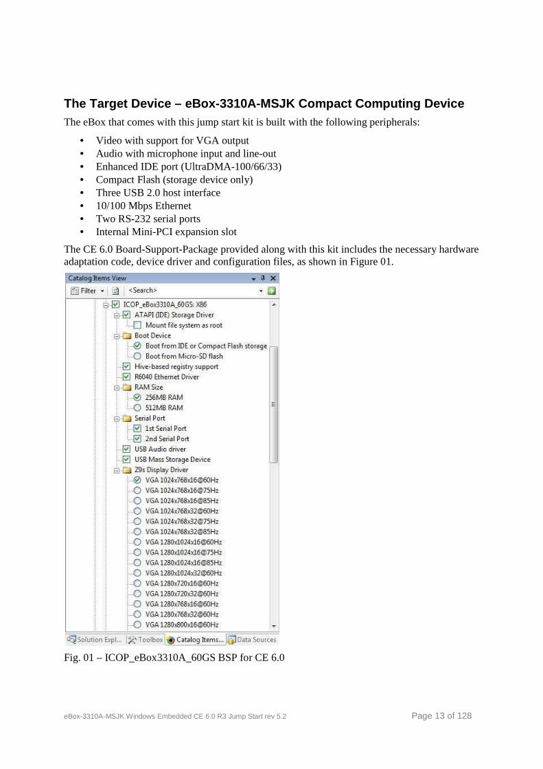
The Target Device – eBox-3310A-MSJK Compact Computi ng Device The eBox that comes with this jump start kit is built with the following peripherals:
• Video with support for VGA output • Audio with microphone input and line-out • Enhanced IDE port (UltraDMA-100/66/33) • Compact Flash (storage device only) • Three USB 2.0 host interface • 10/100 Mbps Ethernet • Two RS-232 serial ports • Internal Mini-PCI expansion slot
The CE 6.0 Board-Support-Package provided along with this kit includes the necessary hardware adaptation code, device driver and configuration files, as shown in Figure 01.
Fig. 01 – ICOP_eBox3310A_60GS BSP for CE 6.0
eBox-3310A-MSJK Windows Embedded CE 6.0 R3 Jump Start rev 5.2 Page 14 of 128
Part 3 – Jump Start Kit Software & Installation The following software packages are provided with the eBox-3310A-MSJK Jump Start kit:
• Visual Studio 2005 Professional (180 days evaluation version) • Windows Embedded CE 6.0 R2 (180 days evaluation version)
Windows Embedded CE 6.0 R3 update is available for download from the following URL: http://www.microsoft.com/downloads/details.aspx?displaylang=en&FamilyID=bc247d88-ddb6-4d4a-a595-8eee3556fe46
Note: CE 6.0 R3 is not required to work through the exercises in this guide. However, installing CE 6.0 R3 will provide additional useful components, which you can include to the OS design project and enhance the function and features.
• ICOP_eBox3310A_60GS Board-Support-Package for the eBox • eBox3310A_WINCE600_SDK Software Development Kit for the eBox • CoreCon component (CoreCon_v200_x86) needed to establish connectivity between the CE 6.0
device and Visual Studio IDE • AutoLaunch component (AutoLaunch_v200_x86), an utility for launching one or more
application when CE 6.0 start • RegFlushApp component, a CE 6.0 utility to flush the system registry • Sample project codes
Visual Studio 2005 Professional Visual Studio 2005 (VS2005) is a popular developer friendly development tool for developing broad range of applications that run on different version of the Windows operating system. Using the VS2005 develop tool, developer can create applications for the following Windows operating system:
• Windows 95, Windows 98, Windows ME and Windows 2000 legacy operating system. • Windows XP • Windows Vista • Windows 2000 Server • Windows 2003 Server • Windows 2008 Server • PocketPC • Windows Mobile Smartphones • Windows Embedded CE devices
The 180 days evaluation version of the VS2005 Professional is fully functional. Other than the 180 days time limit, it has all of the features as the full version.
Windows Embedded CE 6.0 Platform Builder Windows Embedded CE 6.0 Platform Builder is a plug-in to the VS2005’s Integrated-Development-Environment (IDE), and takes advantage of the VS2005 IDE tools. The latest release, Windows Embedded CE 6.0 R3, is an incremental release to provide additional features and technologies. For the purpose of this guide, we will refer to “Windows Embedded CE 6.0”, “Windows Embedded CE 6.0 R2” and “Windows Embedded CE 6.0 R3” as “CE 6.0”.
The 180 days evaluation version of the Windows Embedded CE 6.0 R2 is fully functional. Other than the 180 days time limit, it has all of the features as the full version.
The CE 6.0 R3 release is available for download from Microsoft website.

eBox-3310A-MSJK Windows Embedded CE 6.0 R3 Jump Start rev 5.2 Page 15 of 128
Board-Support-Package Board-Support-Package (BSP) consists of all necessary CE 6.0 device drivers and hardware abstraction library and configuration files to support the targeted device, and is needed by the CE 6.0 Platform Builder to create OS design and generate CE 6.0 OS runtime image for the targeted device. The ICOP_eBox3310A_60GS BSP is provided as part of this jump start kit to create the OS design and generate CE 6.0 OS runtime image for the eBox. This BSP is provided with the jump start kit CD in the \Software folder.
CoreCon Connectivity CoreCon is needed to establish connectivity between the CE 6.0 target device and the Visual Studio (2005 and 2008) IDE for the purpose of developing application and downloading the application onto the target device for testing and debug. The CoreCon files are installed to the development workstation as part of the VS2005 and VS2008 installation to the following folder on the development workstation:
\Program Files\Common Files\Microsoft shared\CoreC on\1.0\Target\WCE400\<CPU>
There are multiple set of CoreCon files installed to sub-folder under the above directory, to support multiple processor family, with the processor family as the sub-folder name. Each of these CoreCon files supports a designated processor family. Since the eBox is engineered with an x86 processor, the CoreCon files in the following folder are used.
\Program Files\Common Files\Microsoft shared\CoreC on\1.0\Target\WCE400\x86\
To establish connectivity between the Visual Studio IDE and the CE 6.0 target device, the appropriate CoreCon files need to be copied to the target device’s local storage, or make available to the target device via Network share or external storage device.
To help ease the process of including the required CoreCon files to the OS design, an installable CoreCon component for CE 6.0, CoreCon_v200_x86_WinCE600.msi , is provided with this jump start kit. Locate and launch the CoreCon_v200_x86_WinCE600.msi installation file from the jump start kit CD, in the \Software folder.
There are different versions of CoreCon. CoreCon version 8.0 is installed with VS2005. When VS2008 is installed, it updates the CoreCon to version 9.0.
A development workstation with both VS2005 and 2008 installed will have CoreCon version 9.0.
CE 6.0 image built with different version of CoreCon from one development workstation will not be able to establish connectivity to another development workstation with different version of CoreCon.
After installing the CoreCon_v200_x86_WinCE600.msi file, the CoreCon component shows up under the \Third Party\CoreCon folder on the CE 6.0 Platform Builder IDE’s component catalog as CoreCon_v200_x86. When selected and included to the OS design, the necessary CoreCon files are included as part of the OS runtime image.
The CoreCon_v200_x86 component does not include the binary files for CoreCon. When the CoreCon_v200_x86 component is included in the OS design, it references and includes the CoreCon files already installed to the development workstation, as part of the Visual Studio (2005 & 2008) installation, to the OS runtime image.
By following the steps in the jump start guide to create an OS design, generate the OS runtime image, with CoreCon_v200_x86 component selected, and download the image to the target device. The runtime image will have the same version of CoreCon installed to the development
eBox-3310A-MSJK Windows Embedded CE 6.0 R3 Jump Start rev 5.2 Page 16 of 128
workstation to support connectivity between the target device and the development workstation’s VS2005 and VS2008 IDE.
In addition to including the necessary CoreCon files with the OS runtime image, the CoreCon executable must be launched from the target device in order for the Visual Studio IDE to establish connection to the target device.
The AutoLaunch component is provided to automatically launch the CoreCon executable when the CE 6.0 OS starts.
AutoLaunch Component The AutoLaunch component is provided to help make it easier to automatically launch application when the CE 6.0 OS starts. When included in the OS runtime image, it can be configured to launch one or more application automatically and specify delay time to launch multiple applications in designated sequences when the CE 6.0 OS starts.
The AutoLaunch component is provided as a self installable file, AutoLaunch_v200_x86_WinCE600.msi , in the \Software folder. After installation, the AutoLaunch_v200_x86 component shows up as one of the components on the Platform Builder’s component catalog, in the Third Party folder.
The AutoLaunch_v200_x86 component files are installed to the following folder by default: C:\WINCE600\3rdparty\AutoLaunch_v200_x86\
To use this component, in addition to including the component to the OS design, add the following registry entries to launch the designated application(s), to the Project.reg file.
[HKEY_LOCAL_MACHINE\Startup] "Process0"="app1.exe <startup parameter>" ; fir st app
"Process0Delay"=dword:00001388 ; delay 5 sec onds ; 13 88 Hex = 5000 in decimal
"Process1"="app2.exe" ; second app "Process1Delay"=dword:2710 ; delay 1 0 seconds "Process2"="app3.exe" ; third app "Process2Delay"=dword:3A98 ; delay 1 5 seconds
RegFlushApp Component The RegFlushApp component contains a Win32 application with a simple function to call the RegFlushKey() function, to flush and save changes to the registry to the persistence storage.
With Hive-based registry enabled, to save changes made to the registry, the system needs to have a way to flush and save these changes to the persistence storage. There are multiple methods to accomplish this:
• One of the methods is to enable Flush-On-Close registry flushing. With this option enabled, the RegFlushKey function is called every time the RegCloseKey is called. This method can have significant impact to system performance. To enable Flush-On-Close registry flushing, add the following registry entries to the OS design: [HKEY_LOCAL_MACHINE\init\BootVars] "RegistryFlags"=dword:1
• Another option to flush the registry is to call the RegFlushKey() function when needed. Since the registry is flush only when it’s needed, and only flush the changes to the persistence storage, this method has minimal impact to system performance.
eBox-3310A-MSJK Windows Embedded CE 6.0 R3 Jump Start rev 5.2 Page 17 of 128
The RegFlushApp component is provided as a self installable file in the \Software folder, RegFlushApp_v100_x86_WINCE600.msi. The RegFlushApp files are installed to the following folder by default:
C:\WINCE600\3rdparty\RegFlushApp\
Note: The RegFlushApp component is provided as a sample utility. In a production environment, it’s best to incorporate the RegFlushKey() function call within the application written for the device.
Sample Project Codes The project codes for the exercises in this jump start guide are provided. The codes are provided on the jump start CD, in the \SampleCodes folder.
Recommended Software Installation Sequences It’s important to install the software in their proper sequences. Here is the recommended software installation sequence, in numeric order.
1. Visual Studio 2005
2. Visual Studio 2005 SP1 If you have the full retail or evaluation version of Windows Embedded CE 6.0 R2 or R3, The VS2005 SP1 installation file is provided on one of the DISC. Otherwise, download from following URL: http://www.microsoft.com/downloads/details.aspx?FamilyID=bb4a75ab-e2d4-4c96-b39d-37baf6b5b1dc&DisplayLang=en
3. Visual Studio 2005 SP1 update for Vista If you have the full retail or evaluation version of Windows Embedded CE 6.0 R2 or R3, The VS2005 SP1 update for Vista installation file is provided on one of the DISC. Otherwise, download from the following URL: http://www.microsoft.com/downloads/details.aspx?FamilyID=90e2942d-3ad1-4873-a2ee-4acc0aace5b6&DisplayLang=en Note: If you are using Windows XP machine, skip this step.
4. Windows Embedded CE 6.0
5. Windows Embedded CE 6.0 SP1
6. Windows Embedded CE 6.0 R2
7. Windows Embedded CE 6.0 R3
8. ICOP_eBox3310A_60GS_BSP.msi This BSP is provided on the jump start kit CD, in the \Software folder.
9. eBox3310A_WINCE600_SDK.msi This SDK is provided on the jump start kit CD, in the \Software folder.
10. CoreCon_v200_x86_WinCE600.msi This CoreCon component is provided on the jump start kit CD, in the \Software folder.
eBox-3310A-MSJK Windows Embedded CE 6.0 R3 Jump Start rev 5.2 Page 18 of 128
11. AutoLaunch_v200_x86_WinCE600.msi This AutoLaunch component is provided on the jump start kit CD, in the \Software folder.
12. RegFlushApp_v100_x86_WinCE600.msi This RegFlushApp component is provided in the jump start kit CD, in the \Software folder.
New version and update for ICOP_eBox3310A_60GS_BSP.msi, eBox3310A_WINCE600_SDK.msi, CoreCon_v200_x86_WinCE600.msi, AutoLaunch_v200_x86_WinCE600.msi and other Windows Embedded CE resources are available from the following URL:
http://www.embeddedpc.net/download/
Windows Embedded CE 6.0 Installation Since the CE 6.0 development tool, Platform Builder, is a plug-in for the VS2005 IDE, the VS2005 development tool must be installed to the develop workstation prior to installing the CE 6.0 software packages. While the CE 6.0 installation does not require VS2005 SP1 to be installed, it’s required to install SDK generated by the Platform Builder. The SDK for the OS design used to generate the OS runtime image is needed to support VS2005 application development. For Windows Vista machine, VS2005 SP1 Update for Vista is also needed.
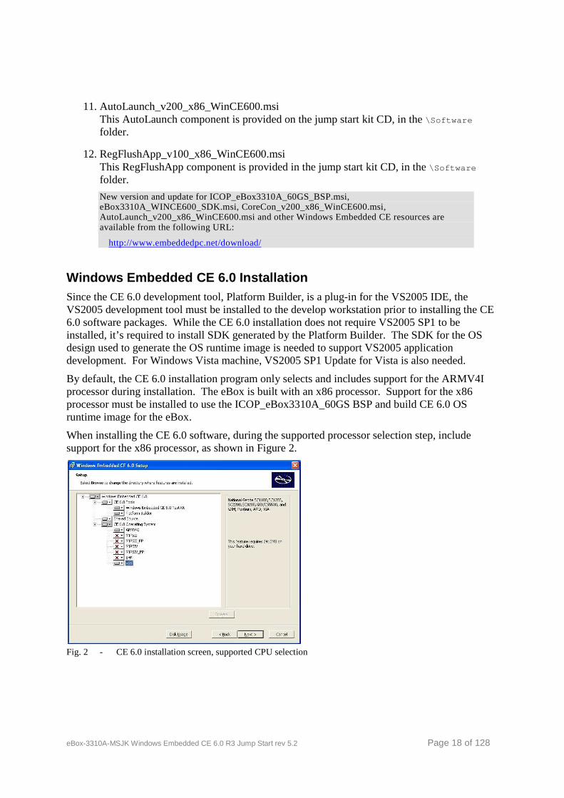
By default, the CE 6.0 installation program only selects and includes support for the ARMV4I processor during installation. The eBox is built with an x86 processor. Support for the x86 processor must be installed to use the ICOP_eBox3310A_60GS BSP and build CE 6.0 OS runtime image for the eBox.
When installing the CE 6.0 software, during the supported processor selection step, include support for the x86 processor, as shown in Figure 2.
Fig. 2 - CE 6.0 installation screen, supported CPU selection
eBox-3310A-MSJK Windows Embedded CE 6.0 R3 Jump Start rev 5.2 Page 19 of 128
Windows Embedded CE 6.0 SP1 Installation After installing the CE 6.0 software, install the CE 6.0 SP1 update. Depending on the version of CE 6.0 CD or DVD being used to install the software, the CE 6.0 SP1 update may be provided as part of the CD or DVD. Otherwise, download and install CE 6.0 SP1 from the following URL:
http://www.microsoft.com/downloads/details.aspx?FamilyID=bf0dc0e3-8575-4860-a8e3-290adf242678&DisplayLang=en
Windows Embedded CE 6.0 R2 Installation After installing the CE 6.0 SP1, install the CE 6.0 R2 update. Depending on the version of CE 6.0 CD or DVD being used to install the software, the CE 6.0 R2 update may be provided as part of the CD or DVD. Otherwise, download and install CE 6.0 R2 from the following URL:
http://www.microsoft.com/downloads/details.aspx?FamilyID=f41fc7c1-f0f4-4fd6-9366-b61e0ab59565&DisplayLang=en
Windows Embedded CE 6.0 R3 Installation After installing the CE 6.0 R2, install the CE 6.0 R3 update. Depending on the version of CE 6.0 CD or DVD being used to install the software, the CE 6.0 R3 update may be provided as part of the CD or DVD. Otherwise, download and install CE 6.0 R3 from the following URL:
http://www.microsoft.com/downloads/details.aspx?displaylang=en&FamilyID=bc247d88-ddb6-4d4a-a595-8eee3556fe46
Board-Support-Package Installation VS2005, CE 6.0, CE 6.0 SP1, CE 6.0 R2 and CE 6.0 R3 must be installed prior to installing the Board-Support-Package (BSP).
The ICOP_eBox3310A_60GS BSP is provided on the jump start CD, in the \Software folder. \Software\ICOP_eBox3310A_60GS.msi
After installation, this BSP component shows up on the CE 6.0 Platform Builder component catalog as “ICOP_eBox3310A_60GS: x86” in the “\Third Party\BSP” folder.
x86 CPU support for CE 6.0 PLATFORM BUILDER is needed in order to use ICOP_eBox3310A_60GS BSP to create OS design and build CE 6.0 image for eBox.
SDK Installation VS2005, CE 6.0, CE 6.0 SP1 and CE 6.0 R3 must be installed prior to installing the SDK.
The CE 6.0 SDK for the eBox-3310A-MSJK, eBox3310A_WINCE600_SDK.msi , is provided on the jump start CD, in the \Software folder.
\Software\eBox3310A_WINCE600_SDK.msi
eBox-3310A-MSJK Windows Embedded CE 6.0 R3 Jump Start rev 5.2 Page 20 of 128
CoreCon Component Installation The CoreCon catalog component for CE 6.0 in self installable file format, CoreCon_v200_x86_WinCE600.msi , is provided with the jump start kit CD. To install, locate and launch this component on the jump start CD, in the \Software directory.
\Software\CoreCon_v200_x86.msi
After installation, this component shows up on the CE 6.0 Platform Builder component catalog as “CoreCon_v200_x86” in the “\Third Party\CoreCon” folder.
AutoLaunch Component Installation The AutoLaunch catalog component for CE 6.0 in self installable file format, AutoLaunch_v200_x86_WinCE600.msi , is provided with the jump start kit CD. To install, locate and launch this component on the jump start CD, in the \Software directory.
\Software\AutoLaunch_v200_x86.msi
After installation, this component shows up on the CE 6.0 Platform Builder component catalog as “AutoLaunch_v200_x86” in the “\Third Party\AutoLaunch” folder.
RegFlushApp Component Installation The RegFlushApp catalog component for CE 6.0 in self installable file format, RegFlushApp_v100_x86_WinCE600.msi , is provided with the jump start kit CD. To install, locate and launch this component on the jump start CD, in the \Software directory.
\Software\RegFlushApp_v100_x86.msi
After installation, this component shows up on the CE 6.0 Platform Builder component catalog as “RegFlushApp” in the “\Third Party\RegFlushApp” folder.
eBox-3310A-MSJK Windows Embedded CE 6.0 R3 Jump Start rev 5.2 Page 21 of 128
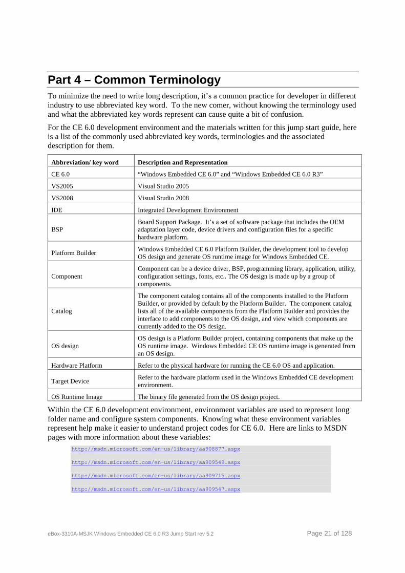
Part 4 – Common Terminology To minimize the need to write long description, it’s a common practice for developer in different industry to use abbreviated key word. To the new comer, without knowing the terminology used and what the abbreviated key words represent can cause quite a bit of confusion.
For the CE 6.0 development environment and the materials written for this jump start guide, here is a list of the commonly used abbreviated key words, terminologies and the associated description for them.
Abbreviation/ key word Description and Representation
CE 6.0 “Windows Embedded CE 6.0” and “Windows Embedded CE 6.0 R3”
VS2005 Visual Studio 2005
VS2008 Visual Studio 2008
IDE Integrated Development Environment
BSP Board Support Package. It’s a set of software package that includes the OEM adaptation layer code, device drivers and configuration files for a specific hardware platform.
Platform Builder Windows Embedded CE 6.0 Platform Builder, the development tool to develop OS design and generate OS runtime image for Windows Embedded CE.
Component Component can be a device driver, BSP, programming library, application, utility, configuration settings, fonts, etc.. The OS design is made up by a group of components.
Catalog
The component catalog contains all of the components installed to the Platform Builder, or provided by default by the Platform Builder. The component catalog lists all of the available components from the Platform Builder and provides the interface to add components to the OS design, and view which components are currently added to the OS design.
OS design OS design is a Platform Builder project, containing components that make up the OS runtime image. Windows Embedded CE OS runtime image is generated from an OS design.
Hardware Platform Refer to the physical hardware for running the CE 6.0 OS and application.
Target Device Refer to the hardware platform used in the Windows Embedded CE development environment.
OS Runtime Image The binary file generated from the OS design project.
Within the CE 6.0 development environment, environment variables are used to represent long folder name and configure system components. Knowing what these environment variables represent help make it easier to understand project codes for CE 6.0. Here are links to MSDN pages with more information about these variables:
http://msdn.microsoft.com/en-us/library/aa908877.as px http://msdn.microsoft.com/en-us/library/aa909549.as px http://msdn.microsoft.com/en-us/library/aa909715.as px http://msdn.microsoft.com/en-us/library/aa909547.as px
eBox-3310A-MSJK Windows Embedded CE 6.0 R3 Jump Start rev 5.2 Page 22 of 128
Part 5 – Configure an OS Design This section will guide you thru the process of creating and configuring an OS design using the New Platform Wizard within Platform Builder. After the initial OS design workspace is created, you can make additional customization by removing components from the project, add additional CE 6.0 components from the catalog and make changes to the registry to control how the final CE 6.0 OS runtime image behave.
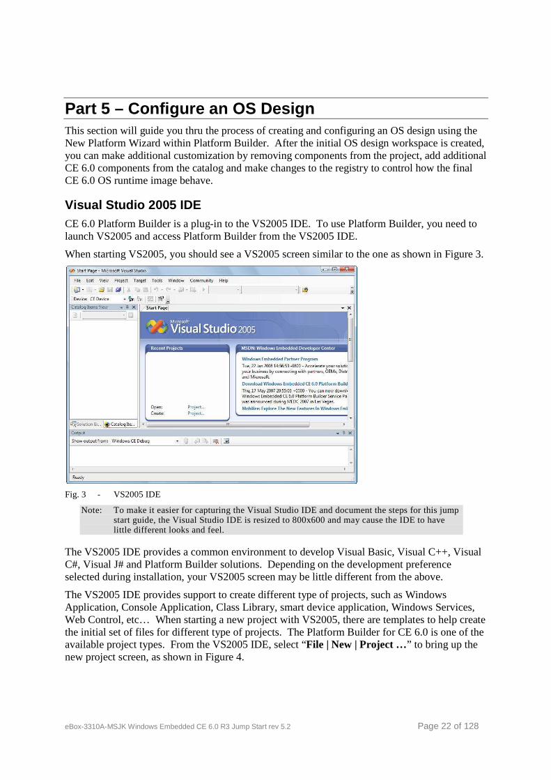
Visual Studio 2005 IDE CE 6.0 Platform Builder is a plug-in to the VS2005 IDE. To use Platform Builder, you need to launch VS2005 and access Platform Builder from the VS2005 IDE.
When starting VS2005, you should see a VS2005 screen similar to the one as shown in Figure 3.
Fig. 3 - VS2005 IDE
Note: To make it easier for capturing the Visual Studio IDE and document the steps for this jump start guide, the Visual Studio IDE is resized to 800x600 and may cause the IDE to have little different looks and feel.
The VS2005 IDE provides a common environment to develop Visual Basic, Visual C++, Visual C#, Visual J# and Platform Builder solutions. Depending on the development preference selected during installation, your VS2005 screen may be little different from the above.
The VS2005 IDE provides support to create different type of projects, such as Windows Application, Console Application, Class Library, smart device application, Windows Services, Web Control, etc… When starting a new project with VS2005, there are templates to help create the initial set of files for different type of projects. The Platform Builder for CE 6.0 is one of the available project types. From the VS2005 IDE, select “File | New | Project …” to bring up the new project screen, as shown in Figure 4.
eBox-3310A-MSJK Windows Embedded CE 6.0 R3 Jump Start rev 5.2 Page 23 of 128
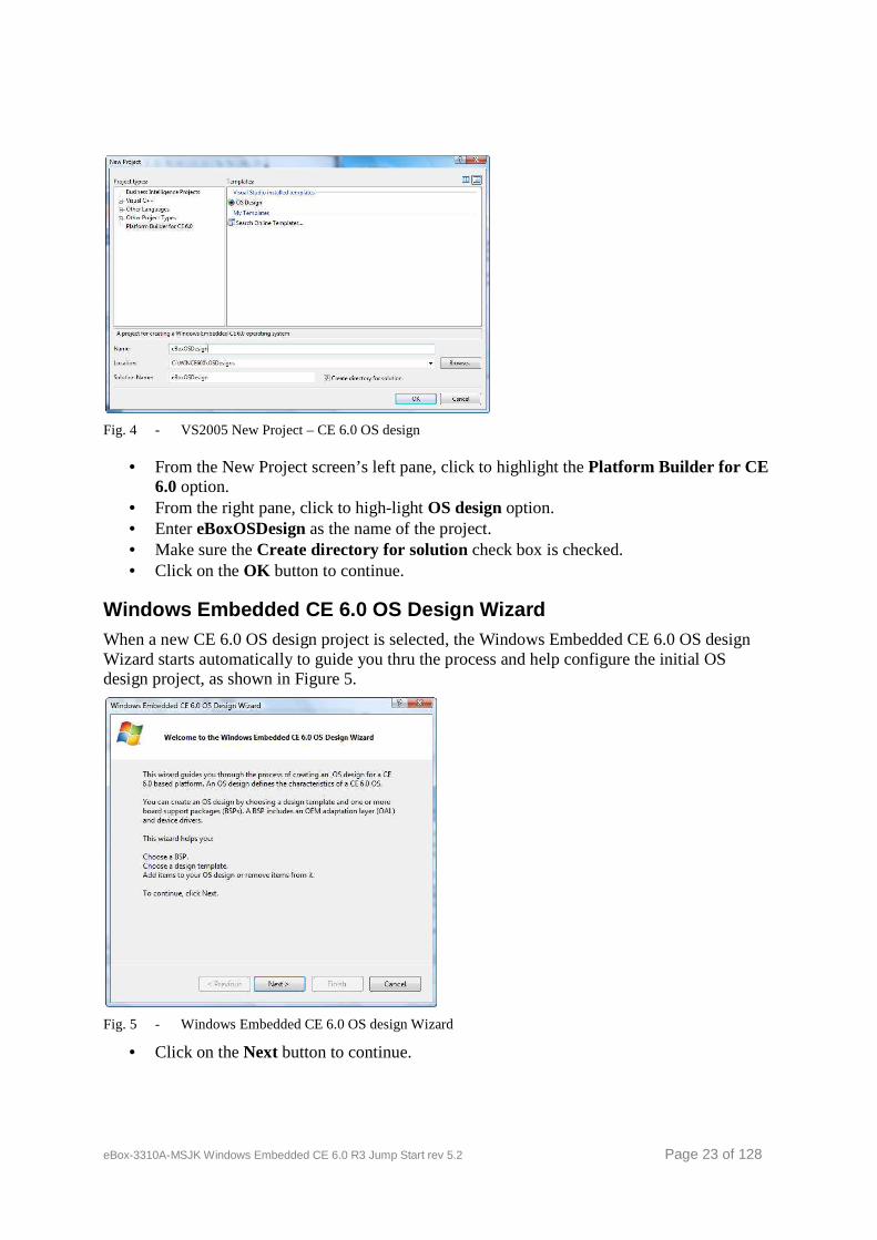
Fig. 4 - VS2005 New Project – CE 6.0 OS design
• From the New Project screen’s left pane, click to highlight the Platform Builder for CE 6.0 option.
• From the right pane, click to high-light OS design option. • Enter eBoxOSDesign as the name of the project. • Make sure the Create directory for solution check box is checked. • Click on the OK button to continue.
Windows Embedded CE 6.0 OS Design Wizard When a new CE 6.0 OS design project is selected, the Windows Embedded CE 6.0 OS design Wizard starts automatically to guide you thru the process and help configure the initial OS design project, as shown in Figure 5.
Fig. 5 - Windows Embedded CE 6.0 OS design Wizard
• Click on the Next button to continue.
eBox-3310A-MSJK Windows Embedded CE 6.0 R3 Jump Start rev 5.2 Page 24 of 128
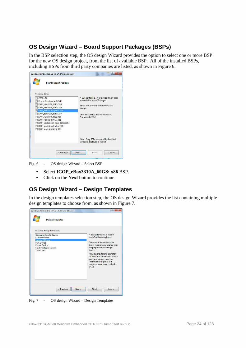
OS Design Wizard – Board Support Packages (BSPs) In the BSP selection step, the OS design Wizard provides the option to select one or more BSP for the new OS design project, from the list of available BSP. All of the installed BSPs, including BSPs from third party companies are listed, as shown in Figure 6.
Fig. 6 - OS design Wizard – Select BSP
• Select ICOP_eBox3310A_60GS: x86 BSP. • Click on the Next button to continue.
OS Design Wizard – Design Templates In the design templates selection step, the OS design Wizard provides the list containing multiple design templates to choose from, as shown in Figure 7.
Fig. 7 - OS design Wizard – Design Templates
eBox-3310A-MSJK Windows Embedded CE 6.0 R3 Jump Start rev 5.2 Page 25 of 128
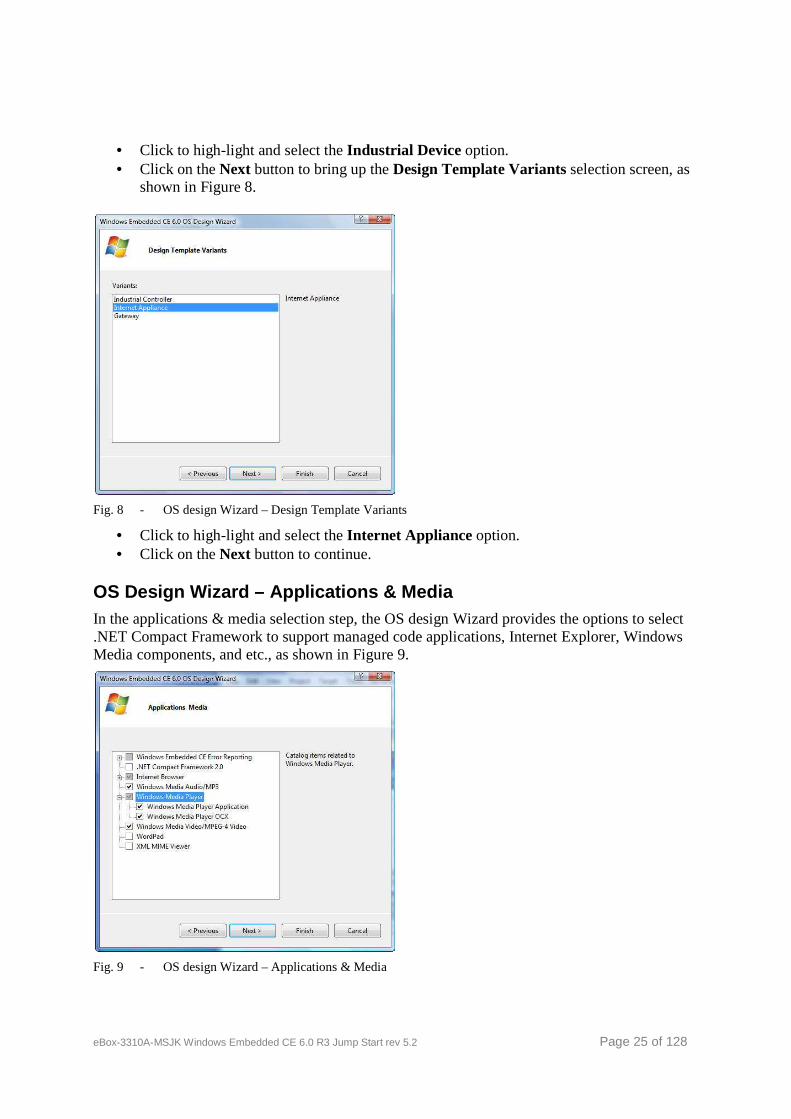
• Click to high-light and select the Industrial Device option. • Click on the Next button to bring up the Design Template Variants selection screen, as
shown in Figure 8.
Fig. 8 - OS design Wizard – Design Template Variants
• Click to high-light and select the Internet Appliance option. • Click on the Next button to continue.
OS Design Wizard – Applications & Media In the applications & media selection step, the OS design Wizard provides the options to select .NET Compact Framework to support managed code applications, Internet Explorer, Windows Media components, and etc., as shown in Figure 9.
Fig. 9 - OS design Wizard – Applications & Media
eBox-3310A-MSJK Windows Embedded CE 6.0 R3 Jump Start rev 5.2 Page 26 of 128
In this step, select the following components.
• Uncheck the .NET Compact Framework 2.0 to remove from the selection. (In the later step, we will include a newer version, .NET Compact Framework 3.5)
• Internet Explorer 6.0 • Windows Media Audio/MP3 • Windows Media Player Application • Windows Media Player OCX • Windows Media Video/MPEG-4 Video • Click on the Next button to continue
Note: .NET Compact Framework is selected to support managed code application. In this step, the .NET Compact Framework 2.0 library is excluded. In the later step, we will add .NET Compact Framework 3.5 to the OS design.
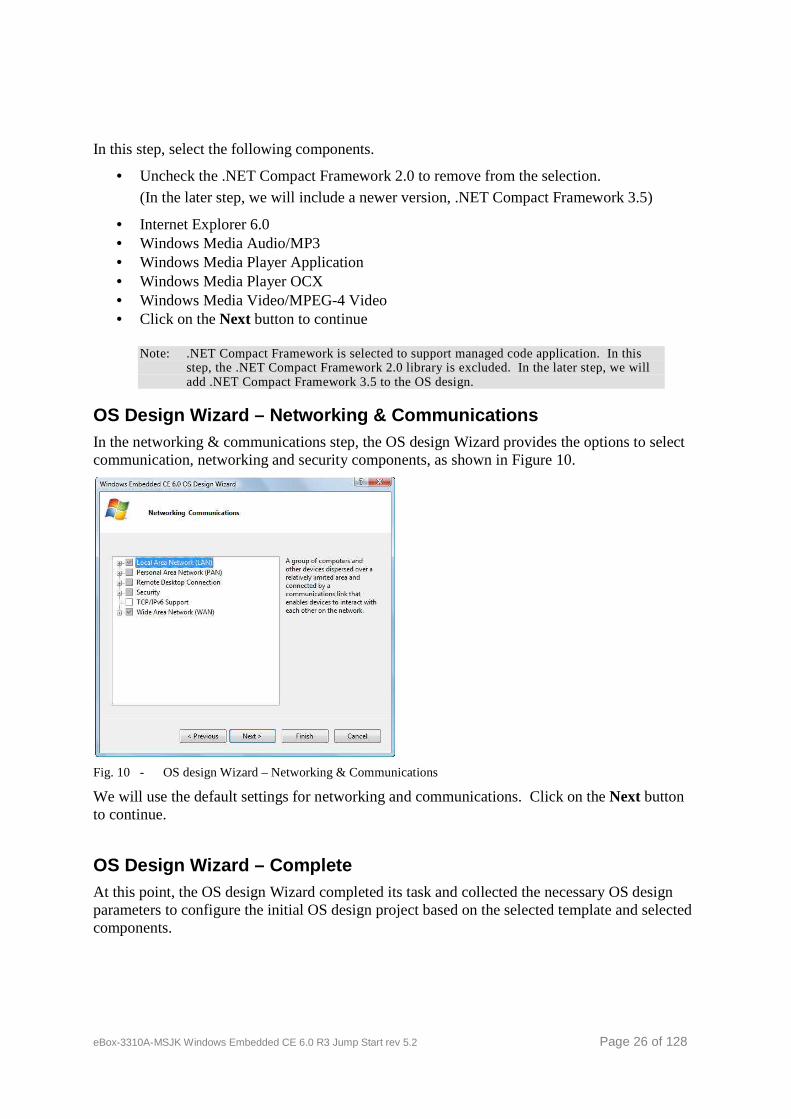
OS Design Wizard – Networking & Communications In the networking & communications step, the OS design Wizard provides the options to select communication, networking and security components, as shown in Figure 10.
Fig. 10 - OS design Wizard – Networking & Communications
We will use the default settings for networking and communications. Click on the Next button to continue.
OS Design Wizard – Complete At this point, the OS design Wizard completed its task and collected the necessary OS design parameters to configure the initial OS design project based on the selected template and selected components.
eBox-3310A-MSJK Windows Embedded CE 6.0 R3 Jump Start rev 5.2 Page 27 of 128
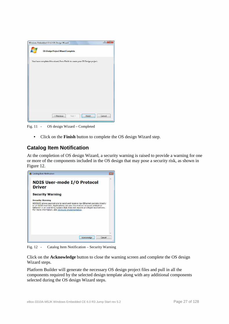
Fig. 11 - OS design Wizard – Completed
• Click on the Finish button to complete the OS design Wizard step.
Catalog Item Notification At the completion of OS design Wizard, a security warning is raised to provide a warning for one or more of the components included in the OS design that may pose a security risk, as shown in Figure 12.
Fig. 12 - Catalog Item Notification – Security Warning
Click on the Acknowledge button to close the warning screen and complete the OS design Wizard steps.
Platform Builder will generate the necessary OS design project files and pull in all the components required by the selected design template along with any additional components selected during the OS design Wizard steps.
eBox-3310A-MSJK Windows Embedded CE 6.0 R3 Jump Start rev 5.2 Page 28 of 128
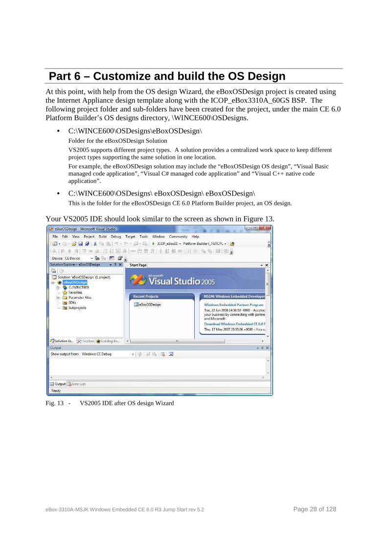
Part 6 – Customize and build the OS Design At this point, with help from the OS design Wizard, the eBoxOSDesign project is created using the Internet Appliance design template along with the ICOP_eBox3310A_60GS BSP. The following project folder and sub-folders have been created for the project, under the main CE 6.0 Platform Builder’s OS designs directory, \WINCE600\OSDesigns.
• C:\WINCE600\OSDesigns\eBoxOSDesign\ Folder for the eBoxOSDesign Solution
VS2005 supports different project types. A solution provides a centralized work space to keep different project types supporting the same solution in one location.
For example, the eBoxOSDesign solution may include the “eBoxOSDesign OS design”, “Visual Basic managed code application”, “Visual C# managed code application” and “Visual C++ native code application”.
• C:\WINCE600\OSDesigns\ eBoxOSDesign\ eBoxOSDesign\ This is the folder for the eBoxOSDesign CE 6.0 Platform Builder project, an OS design.
Your VS2005 IDE should look similar to the screen as shown in Figure 13.
Fig. 13 - VS2005 IDE after OS design Wizard
eBox-3310A-MSJK Windows Embedded CE 6.0 R3 Jump Start rev 5.2 Page 29 of 128
Customize the OS Design – Additional Catalog Compon ents We can further customize the OS design by selecting additional components from the Platform Builder component catalog, add application and library as subproject or make changes to the registry.
The Catalog Item View window lists all of the available CE 6.0 components, including applications, library, drivers, utilities & 3rd party components that can be added to the OS design. An existing set of components are included in the OS design by the Wizard based on the BSP and design template selected during the OS design Wizard phase.
Additional components (drivers, utilities, applications, etc.) from the component catalog can be added to the OS design to enhance function and features.
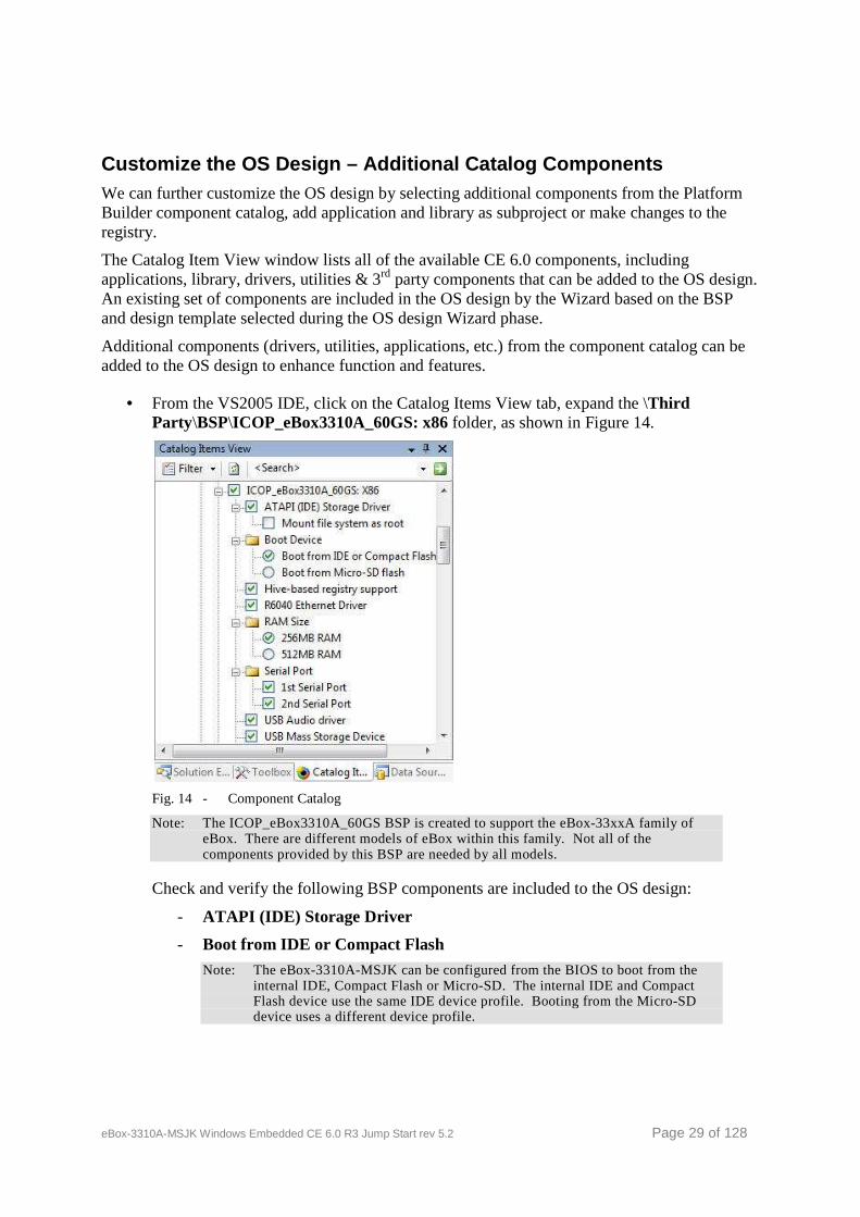
• From the VS2005 IDE, click on the Catalog Items View tab, expand the \Third Party\BSP\ICOP_eBox3310A_60GS: x86 folder, as shown in Figure 14.
Fig. 14 - Component Catalog
Note: The ICOP_eBox3310A_60GS BSP is created to support the eBox-33xxA family of eBox. There are different models of eBox within this family. Not all of the components provided by this BSP are needed by all models.
Check and verify the following BSP components are included to the OS design:
- ATAPI (IDE) Storage Driver
- Boot from IDE or Compact Flash
Note: The eBox-3310A-MSJK can be configured from the BIOS to boot from the internal IDE, Compact Flash or Micro-SD. The internal IDE and Compact Flash device use the same IDE device profile. Booting from the Micro-SD device uses a different device profile.

eBox-3310A-MSJK Windows Embedded CE 6.0 R3 Jump Start rev 5.2 Page 30 of 128
- Hive-based registry support
Note: The Hive-based registry component is needed to save registry settings to non volatile flash storage when the eBox power off.
- R6040 Ethernet driver
Note: The R6040 Ethernet controller is built-in to the Vortex86DX System-On-Chip.
- 256MB RAM
Note: The eBox-3310A-MSJK is built with 256MB of system memory. This component set the IMGRAM256 environment variable and configure the OS runtime image to use the 256MB of available system memory.
- 1st Serial Port
- 2nd Serial Port
- USB Audio driver
- USB Mass Storage Device
Note: This component set the SYSGEN_USB_STORAGE environment variable to include the USB storage class driver to the OS runtime image to support external USB storage.
- VGA 1024x768x16 @ 60Hz
Note: You can select a different display setting supported by the display monitor you are working with.
• Expand \Core OS\CEBASE folder, locate and include the following components to the OS design.
- \Applications-End User\CAB File Installer/Uninstaller This component provides application installation & removal support. It’s needed for application development using VS2005 and VS2008.
• .NET Compact Framework components are needed to support managed code application. During the OS design wizard steps, .NET Compact Framework 2.0 components were removed from the selection. Select the following newer version of the .NET Compact Framework from the component catalog.
- .NET Compact Framework 3.5
- OS Dependencies for .NET Compact Framework 3.5
If you are using an earlier release of the CE 6.0, .NET Compact Framework 3.5 is available as part of the January 2008 QFE updates for CE 6.0.
Otherwise, you can include the .NET Compact Framework 2.0 components to the OS design.
• Expand \Third Party\CoreCon folder and select the CoreCon_v200_x86 component. By selecting this component, the CoreCon component files are included to the OS runtime image, needed to establish connection between the CE 6.0 device and VS2005 (or VS2008) development workstation.
To establish connection between the CE 6.0 device and VS2005 development workstation, the CoreCon component need to be launched from the CE 6.0 device when CE 6.0 starts. To

eBox-3310A-MSJK Windows Embedded CE 6.0 R3 Jump Start rev 5.2 Page 31 of 128
accomplish this, we use the AutoLaunch utility to launch the CoreCon component when CE 6.0 starts. The following step add the AutoLaunch component to the OS design.
• From the \Third Party\AutoLaunch folder, select and include the AutoLaunch_v200_x86 component to the OS design.
With the appropriate registry entries, the AutoLaunch utility can be configured to launch one or more application automatically when the CE 6.0 OS starts.
[HKEY_LOCAL_MACHINE\Startup] “Process1”=”App1.exe” “Process1Delay”=dword:00001388 ; delay 5s 1388(Hex) = 5000(decimal) “Process2”=”App2.exe” “Process2Delay”=dword:00002710 ; delay 5s 2710(Hex) = 10000(decimal)
• From the \Third Party\RegFlushApp folder, select and include the RegFlushApp component to the OS design. When this component is selected, the RegFlushApp.exe application is included in the OS design and built as part of the runtime image.
The RegFlushApp application works in conjunction with Hive-based registry. With Hive-based registry enabled, when changes are made to the registry, the system needs a mechanism to save these changes. The RegFlushApp, when launched, call the RegFlushKey() function to flush and save the registry.
The RegFlushApp is accessible from the Start menu on the CE 6.0 desktop, as follow:
Start | Programs | RegFlushApp
Customize the OS Design – Locate Component by Searc h The Platform Builder IDE also provides a search function to locate component from the catalog by searching the catalog using partial key word associated with the component. In this section, we will demonstrate how to locate a component from the catalog using the search function.
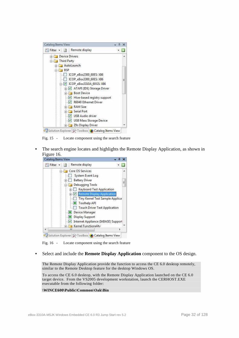
• From the Catalog Item View tab, enter “Remote display” in the search text box on the top right corner, as shown in Figure 15, and click on the green arrow to the right of the search text box to search.
eBox-3310A-MSJK Windows Embedded CE 6.0 R3 Jump Start rev 5.2 Page 32 of 128
Fig. 15 - Locate component using the search feature
• The search engine locates and highlights the Remote Display Application, as shown in Figure 16.
Fig. 16 - Locate component using the search feature
• Select and include the Remote Display Application component to the OS design.
The Remote Display Application provide the function to access the CE 6.0 desktop remotely, similar to the Remote Desktop feature for the desktop Windows OS.
To access the CE 6.0 desktop, with the Remote Display Application launched on the CE 6.0 target device. From the VS2005 development workstation, launch the CERHOST.EXE executable from the following folder:
\WINCE600\Public\Common\Oak\Bin
eBox-3310A-MSJK Windows Embedded CE 6.0 R3 Jump Start rev 5.2 Page 33 of 128
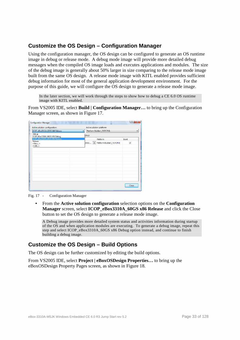
Customize the OS Design – Configuration Manager Using the configuration manager, the OS design can be configured to generate an OS runtime image in debug or release mode. A debug mode image will provide more detailed debug messages when the compiled OS image loads and executes applications and modules. The size of the debug image is generally about 50% larger in size comparing to the release mode image built from the same OS design. A release mode image with KITL enabled provides sufficient debug information for most of the general application development environment. For the purpose of this guide, we will configure the OS design to generate a release mode image.
In the later section, we will work through the steps to show how to debug a CE 6.0 OS runtime image with KITL enabled.
From VS2005 IDE, select Build | Configuration Manager… to bring up the Configuration Manager screen, as shown in Figure 17.
Fig. 17 - Configuration Manager
• From the Active solution configuration selection options on the Configuration Manager screen, select ICOP_eBox3310A_60GS x86 Release and click the Close button to set the OS design to generate a release mode image.
A Debug image provides more detailed system status and activities information during startup of the OS and when application modules are executing. To generate a debug image, repeat this step and select ICOP_eBox3310A_60GS x86 Debug option instead, and continue to finish building a debug image.
Customize the OS Design – Build Options The OS design can be further customized by editing the build options.
From VS2005 IDE, select Project | eBoxOSDesign Properties… to bring up the eBoxOSDesign Property Pages screen, as shown in Figure 18.
eBox-3310A-MSJK Windows Embedded CE 6.0 R3 Jump Start rev 5.2 Page 34 of 128
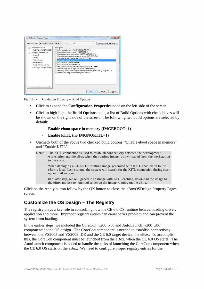
Fig. 18 - OS design Property – Build Options
• Click to expand the Configuration Properties node on the left side of the screen.
• Click to high-light the Build Options node, a list of Build Options with check boxes will be shown on the right side of the screen. The following two build options are selected by default:
- Enable eboot space in memory (IMGEBOOT=1)
- Enable KITL (no IMGNOKITL=1)
• Uncheck both of the above two checked build options, “Enable eboot space in memory” and “Enable KITL”.
Note: The KITL connection is used to establish connectivity between the development workstation and the eBox when the runtime image is downloaded from the workstation to the eBox.
When deploying a CE 6.0 OS runtime image generated with KITL enabled on to the eBox’s local flash storage, the system will search for the KITL connection during start up and fail to boot.
In a later step, we will generate an image with KITL enabled, download the image to the eBox and use remote tool to debug the image running on the eBox.
Click on the Apply button follow by the OK button to close the eBoxOSDesign Property Pages screen.
Customize the OS Design – The Registry The registry plays a key role in controlling how the CE 6.0 OS runtime behave, loading driver, application and more. Improper registry entries can cause series problem and can prevent the system from loading.
In the earlier steps, we included the CoreCon_v200_x86 and AutoLaunch_v200_x86 components to the OS design. The CoreCon component is needed to establish connectivity between the VS2005 and VS2008 IDE and the CE 6.0 target device, the eBox. To accomplish this, the CoreCon component must be launched from the eBox, when the CE 6.0 OS starts. The AutoLaunch component is added to handle the tasks of launching the CoreCon component when the CE 6.0 OS starts on the eBox. We need to configure proper registry entries for the
eBox-3310A-MSJK Windows Embedded CE 6.0 R3 Jump Start rev 5.2 Page 35 of 128
AutoLaunch utility to perform the tasks and launch the CoreCon connectivity when the CE 6.0 OS starts.
Work through the following steps to enter the necessary registry entries to the OS design:
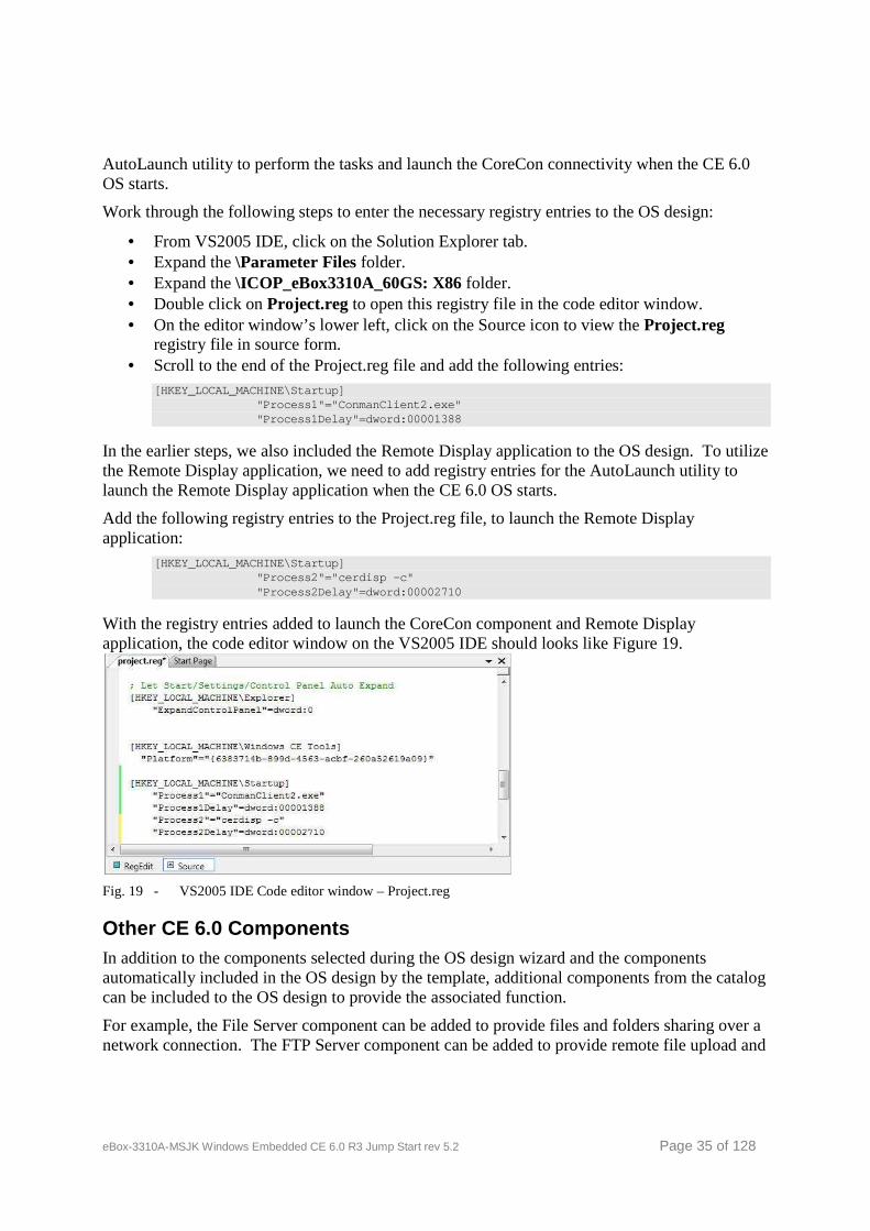
• From VS2005 IDE, click on the Solution Explorer tab. • Expand the \Parameter Files folder. • Expand the \ICOP_eBox3310A_60GS: X86 folder. • Double click on Project.reg to open this registry file in the code editor window. • On the editor window’s lower left, click on the Source icon to view the Project.reg
registry file in source form. • Scroll to the end of the Project.reg file and add the following entries:
[HKEY_LOCAL_MACHINE\Startup] "Process1"="ConmanClient2.exe" "Process1Delay"=dword:00001388
In the earlier steps, we also included the Remote Display application to the OS design. To utilize the Remote Display application, we need to add registry entries for the AutoLaunch utility to launch the Remote Display application when the CE 6.0 OS starts.
Add the following registry entries to the Project.reg file, to launch the Remote Display application:
[HKEY_LOCAL_MACHINE\Startup] "Process2"="cerdisp -c" "Process2Delay"=dword:00002710
With the registry entries added to launch the CoreCon component and Remote Display application, the code editor window on the VS2005 IDE should looks like Figure 19.
Fig. 19 - VS2005 IDE Code editor window – Project.reg
Other CE 6.0 Components In addition to the components selected during the OS design wizard and the components automatically included in the OS design by the template, additional components from the catalog can be included to the OS design to provide the associated function.
For example, the File Server component can be added to provide files and folders sharing over a network connection. The FTP Server component can be added to provide remote file upload and
eBox-3310A-MSJK Windows Embedded CE 6.0 R3 Jump Start rev 5.2 Page 36 of 128
download services. The RAS Server/PPTP Server (Incoming) component can be added to provide inbound dialup network connection via the serial port.
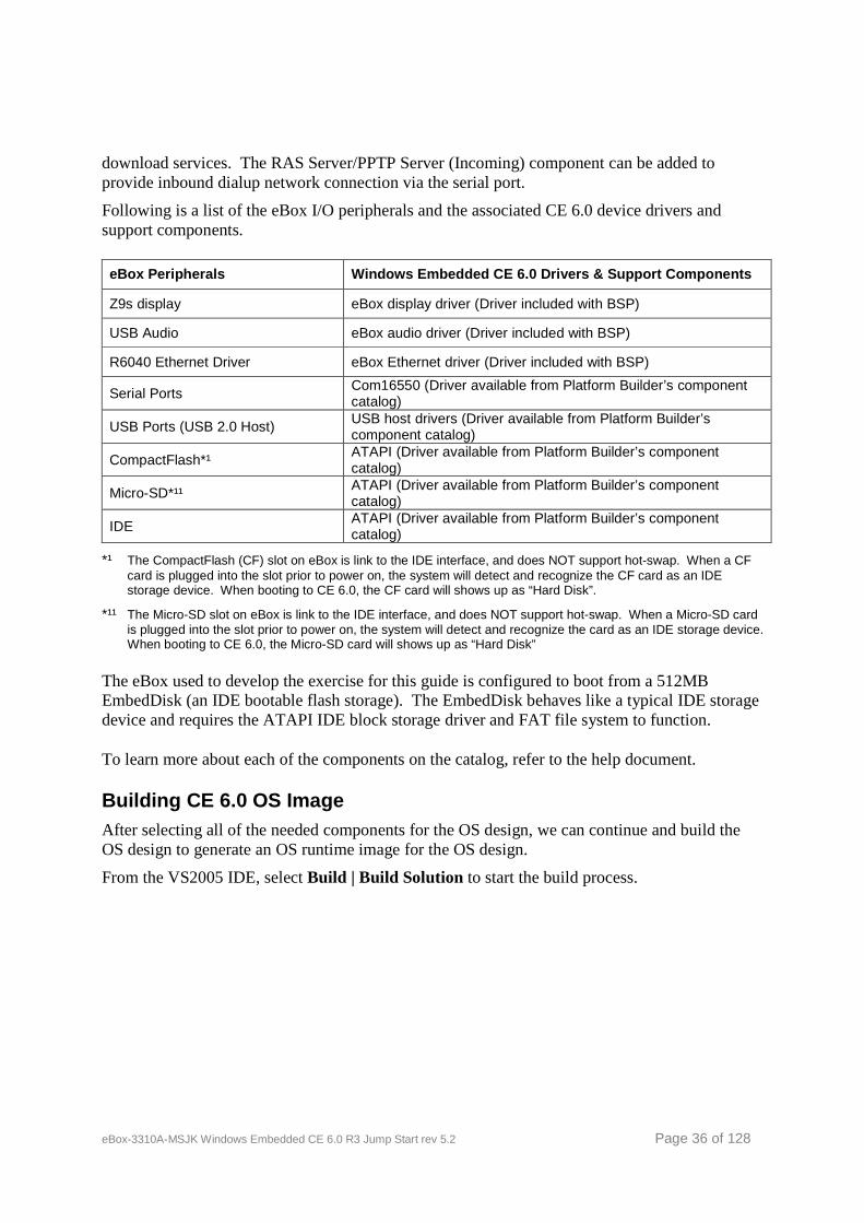
Following is a list of the eBox I/O peripherals and the associated CE 6.0 device drivers and support components.
eBox Peripherals Windows Embedded CE 6.0 Drivers & Support Components
Z9s display eBox display driver (Driver included with BSP)
USB Audio eBox audio driver (Driver included with BSP)
R6040 Ethernet Driver eBox Ethernet driver (Driver included with BSP)
Serial Ports Com16550 (Driver available from Platform Builder’s component catalog)
USB Ports (USB 2.0 Host) USB host drivers (Driver available from Platform Builder’s component catalog)
CompactFlash*¹ ATAPI (Driver available from Platform Builder’s component catalog)
Micro-SD*¹¹ ATAPI (Driver available from Platform Builder’s component catalog)
IDE ATAPI (Driver available from Platform Builder’s component catalog)
*¹ The CompactFlash (CF) slot on eBox is link to the IDE interface, and does NOT support hot-swap. When a CF card is plugged into the slot prior to power on, the system will detect and recognize the CF card as an IDE storage device. When booting to CE 6.0, the CF card will shows up as “Hard Disk”.
*¹¹ The Micro-SD slot on eBox is link to the IDE interface, and does NOT support hot-swap. When a Micro-SD card is plugged into the slot prior to power on, the system will detect and recognize the card as an IDE storage device. When booting to CE 6.0, the Micro-SD card will shows up as “Hard Disk”
The eBox used to develop the exercise for this guide is configured to boot from a 512MB EmbedDisk (an IDE bootable flash storage). The EmbedDisk behaves like a typical IDE storage device and requires the ATAPI IDE block storage driver and FAT file system to function.
To learn more about each of the components on the catalog, refer to the help document.
Building CE 6.0 OS Image After selecting all of the needed components for the OS design, we can continue and build the OS design to generate an OS runtime image for the OS design.
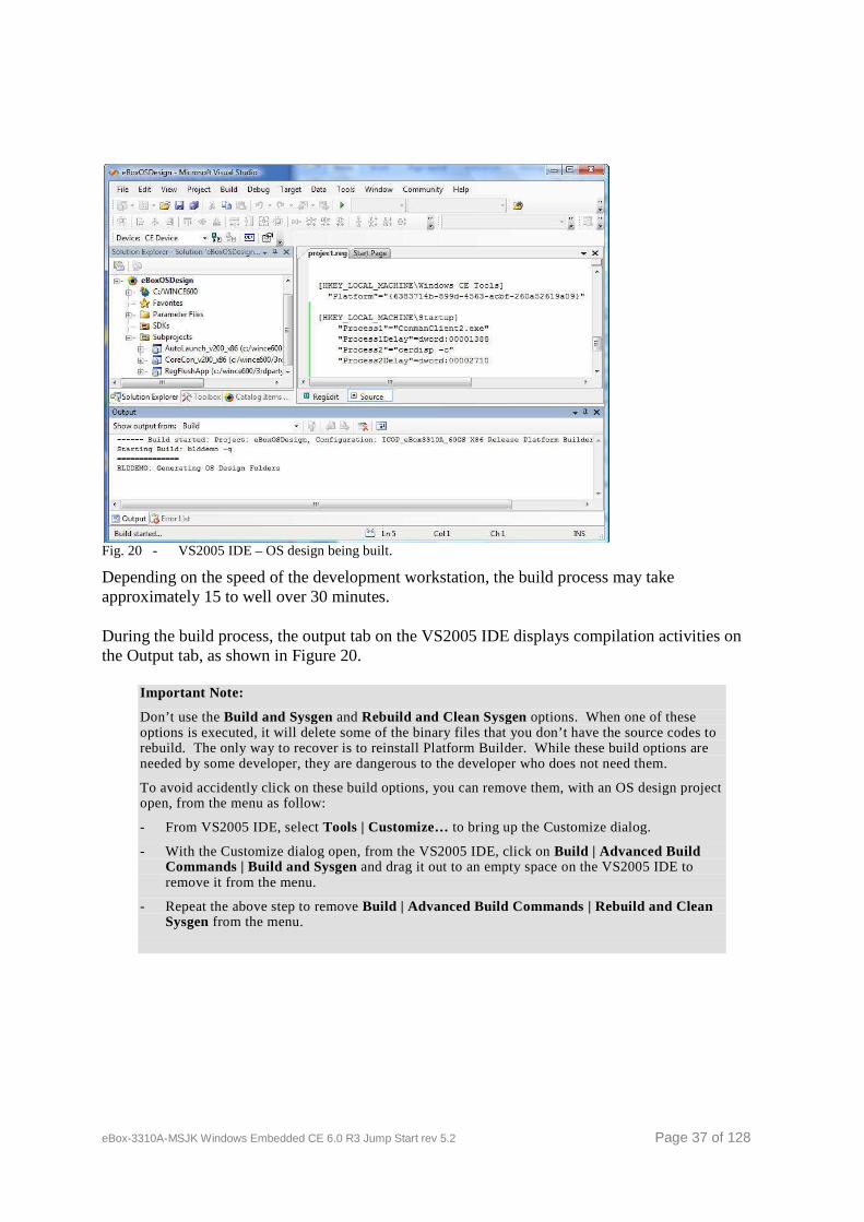
From the VS2005 IDE, select Build | Build Solution to start the build process.
eBox-3310A-MSJK Windows Embedded CE 6.0 R3 Jump Start rev 5.2 Page 37 of 128
Fig. 20 - VS2005 IDE – OS design being built.
Depending on the speed of the development workstation, the build process may take approximately 15 to well over 30 minutes.
During the build process, the output tab on the VS2005 IDE displays compilation activities on the Output tab, as shown in Figure 20.
Important Note:
Don’t use the Build and Sysgen and Rebuild and Clean Sysgen options. When one of these options is executed, it will delete some of the binary files that you don’t have the source codes to rebuild. The only way to recover is to reinstall Platform Builder. While these build options are needed by some developer, they are dangerous to the developer who does not need them.
To avoid accidently click on these build options, you can remove them, with an OS design project open, from the menu as follow:
- From VS2005 IDE, select Tools | Customize… to bring up the Customize dialog.
- With the Customize dialog open, from the VS2005 IDE, click on Build | Advanced Build Commands | Build and Sysgen and drag it out to an empty space on the VS2005 IDE to remove it from the menu.
- Repeat the above step to remove Build | Advanced Build Commands | Rebuild and Clean Sysgen from the menu.
eBox-3310A-MSJK Windows Embedded CE 6.0 R3 Jump Start rev 5.2 Page 38 of 128
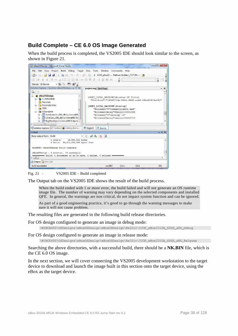
Build Complete – CE 6.0 OS Image Generated When the build process is completed, the VS2005 IDE should look similar to the screen, as shown in Figure 21.
Fig. 21 - VS2005 IDE – Build completed
The Output tab on the VS2005 IDE shows the result of the build process.
When the build ended with 1 or more error, the build failed and will not generate an OS runtime image file. The number of warning may vary depending on the selected components and installed QFE. In general, the warnings are non critical, do not impact system function and can be ignored.
As part of a good engineering practice, it’s good to go through the warning messages to make sure it will not cause problem.
The resulting files are generated in the following build release directories.
For OS design configured to generate an image in debug mode: \WINCE600\OSDesigns\eBoxOSDesign\eBoxOSDesign\RelDi r\ICOP_eBox3310A_60GS_x86_Debug
For OS design configured to generate an image in release mode: \WINCE600\OSDesigns\eBoxOSDesign\eBoxOSDesign\RelDi r\ICOP_eBox3310A_60GS_x86_Release
Searching the above directories, with a successful build, there should be a NK.BIN file, which is the CE 6.0 OS image.
In the next section, we will cover connecting the VS2005 development workstation to the target device to download and launch the image built in this section onto the target device, using the eBox as the target device.
eBox-3310A-MSJK Windows Embedded CE 6.0 R3 Jump Start rev 5.2 Page 39 of 128
Part 7 – Download OS Image to eBox
Preparing the Development Workstation and eBox There are different methods to establish connectivity and download the CE 6.0 OS runtime image from the development workstation to the target device, through an Ethernet interface, serial port, USB or JTAG interface.
For the exercise in this guide, Ethernet is used as the primary connectivity. Both the development workstation and the eBox are attached to the same Local Area Network with DHCP service to provide IP address dynamically.
It’s possible to establish connectivity using a Local Area Network without DHCP service, using static IP addresses.
Please refer to Appendix A and B for more information about connectivity options between the eBox and development workstation.
If you experience problem establishing connection, disable the firewall on the development workstation. The firewall may be blocking the connection.
The eBox that comes with the eBox-3310A-MSJK jump start kit includes a 512MB EmbedDisk (IDE bootable flash storage), configured to boot to DOS using FAT file system. The following software components are included in the EmbedDisk:
• Autoexec.bat This is the startup batch file for the DOS operating system, and is executed each time the operating system is launched.
• Config.sys This is the startup configuration file for the DOS operating system.
• Eboot.bin This is the Ethernet boot loader, needed to establish connectivity between the development workstation and the target device to download CE 6.0 OS runtime image from the development workstation. The Eboot.bin Ethernet boot loader needs to be launched by another boot loader.
• Loadcepc.exe This is the DOS boot loader, used for development purpose. The Loadcepc boot loader can launch CE 6.0 OS runtime image stored on the target device’s local storage, NK.bin. It’s also used to launch the Eboot.bin Ethernet boot loader to establish connectivity with the development workstation and broadcast bootme request to download the CE 6.0 OS runtime image from the development workstation.
• NK.bin This is a CE 6.0 OS runtime image.
eBox-3310A-MSJK Windows Embedded CE 6.0 R3 Jump Start rev 5.2 Page 40 of 128
After power up, the eBox boot to DOS and launches a selection menu with the following options:
1. Load OS image with from local storage 2. Load OS image from development station with DHCP service 3. Load OS image from development station with Static IP 192.168.2.232 4. Clean Boot (no commands)
We will use option 2, Load OS image from development station with DHCP service, for the exercise in this guide.
Development Station with static IP address:
If you are working in an environment without DHCP service, using option 3 and configure your development machine with a proper static IP address. The following is the recommended static IP configuration for the development workstation:
IP Address: 192.168.2.132
Subnet mask: 255.255.255.0
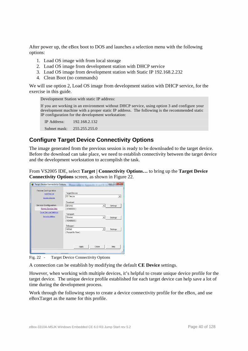
Configure Target Device Connectivity Options The image generated from the previous session is ready to be downloaded to the target device. Before the download can take place, we need to establish connectivity between the target device and the development workstation to accomplish the task.
From VS2005 IDE, select Target | Connectivity Options… to bring up the Target Device Connectivity Options screen, as shown in Figure 22.
Fig. 22 - Target Device Connectivity Options
A connection can be establish by modifying the default CE Device settings.
However, when working with multiple devices, it’s helpful to create unique device profile for the target device. The unique device profile established for each target device can help save a lot of time during the development process.
Work through the following steps to create a device connectivity profile for the eBox, and use eBoxTarget as the name for this profile.
eBox-3310A-MSJK Windows Embedded CE 6.0 R3 Jump Start rev 5.2 Page 41 of 128
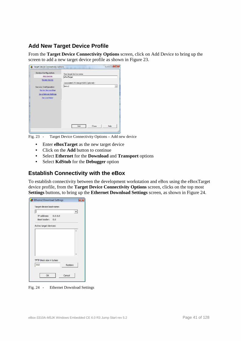
Add New Target Device Profile From the Target Device Connectivity Options screen, click on Add Device to bring up the screen to add a new target device profile as shown in Figure 23.
Fig. 23 - Target Device Connectivity Options – Add new device
• Enter eBoxTarget as the new target device • Click on the Add button to continue • Select Ethernet for the Download and Transport options • Select KdStub for the Debugger option
Establish Connectivity with the eBox To establish connectivity between the development workstation and eBox using the eBoxTarget device profile, from the Target Device Connectivity Options screen, clicks on the top most Settings buttons, to bring up the Ethernet Download Settings screen, as shown in Figure 24.
Fig. 24 - Ethernet Download Settings
eBox-3310A-MSJK Windows Embedded CE 6.0 R3 Jump Start rev 5.2 Page 42 of 128
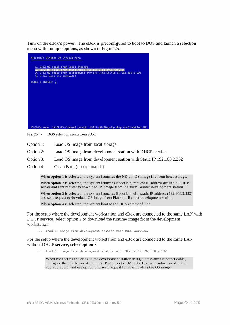
Turn on the eBox’s power. The eBox is preconfigured to boot to DOS and launch a selection menu with multiple options, as shown in Figure 25.
Fig. 25 - DOS selection menu from eBox
Option 1: Load OS image from local storage.
Option 2: Load OS image from development station with DHCP service
Option 3: Load OS image from development station with Static IP 192.168.2.232
Option 4: Clean Boot (no commands)
When option 1 is selected, the system launches the NK.bin OS image file from local storage.
When option 2 is selected, the system launches Eboot.bin, request IP address available DHCP server and sent request to download OS image from Platform Builder development station.
When option 3 is selected, the system launches Eboot.bin with static IP address (192.168.2.232) and sent request to download OS image from Platform Builder development station.
When option 4 is selected, the system boot to the DOS command line.
For the setup where the development workstation and eBox are connected to the same LAN with DHCP service, select option 2 to download the runtime image from the development workstation.
2. Load OS image from development station with DHC P service.
For the setup where the development workstation and eBox are connected to the same LAN without DHCP service, select option 3.
3. Load OS image from development station with Sta tic IP 192.168.2.232
When connecting the eBox to the development station using a cross-over Ethernet cable, configure the development station’s IP address to 192.168.2.132, with subnet mask set to 255.255.255.0, and use option 3 to send request for downloading the OS image.
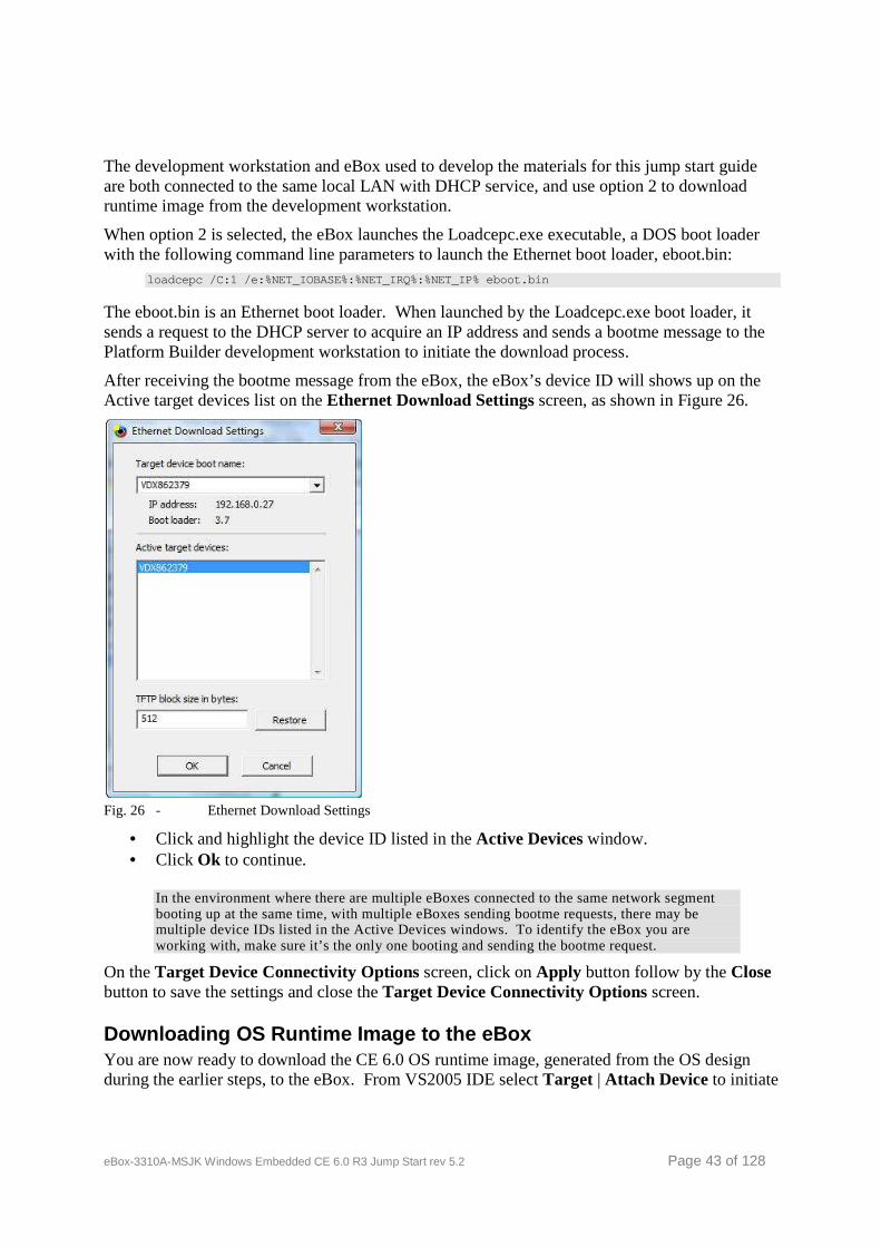
eBox-3310A-MSJK Windows Embedded CE 6.0 R3 Jump Start rev 5.2 Page 43 of 128
The development workstation and eBox used to develop the materials for this jump start guide are both connected to the same local LAN with DHCP service, and use option 2 to download runtime image from the development workstation.
When option 2 is selected, the eBox launches the Loadcepc.exe executable, a DOS boot loader with the following command line parameters to launch the Ethernet boot loader, eboot.bin:
loadcepc /C:1 /e:%NET_IOBASE%:%NET_IRQ%:%NET_IP% eb oot.bin
The eboot.bin is an Ethernet boot loader. When launched by the Loadcepc.exe boot loader, it sends a request to the DHCP server to acquire an IP address and sends a bootme message to the Platform Builder development workstation to initiate the download process.
After receiving the bootme message from the eBox, the eBox’s device ID will shows up on the Active target devices list on the Ethernet Download Settings screen, as shown in Figure 26.
Fig. 26 - Ethernet Download Settings
• Click and highlight the device ID listed in the Active Devices window. • Click Ok to continue.
In the environment where there are multiple eBoxes connected to the same network segment booting up at the same time, with multiple eBoxes sending bootme requests, there may be multiple device IDs listed in the Active Devices windows. To identify the eBox you are working with, make sure it’s the only one booting and sending the bootme request.
On the Target Device Connectivity Options screen, click on Apply button follow by the Close button to save the settings and close the Target Device Connectivity Options screen.
Downloading OS Runtime Image to the eBox You are now ready to download the CE 6.0 OS runtime image, generated from the OS design during the earlier steps, to the eBox. From VS2005 IDE select Target | Attach Device to initiate
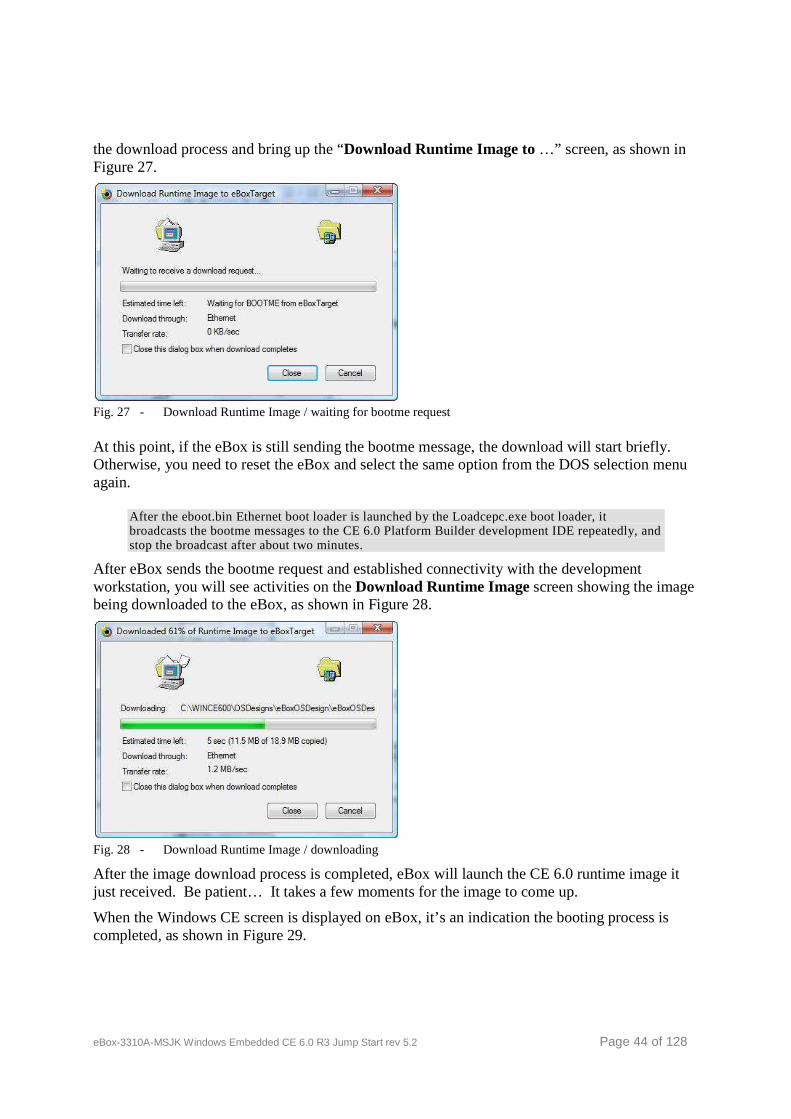
eBox-3310A-MSJK Windows Embedded CE 6.0 R3 Jump Start rev 5.2 Page 44 of 128
the download process and bring up the “Download Runtime Image to …” screen, as shown in Figure 27.
Fig. 27 - Download Runtime Image / waiting for bootme request
At this point, if the eBox is still sending the bootme message, the download will start briefly. Otherwise, you need to reset the eBox and select the same option from the DOS selection menu again.
After the eboot.bin Ethernet boot loader is launched by the Loadcepc.exe boot loader, it broadcasts the bootme messages to the CE 6.0 Platform Builder development IDE repeatedly, and stop the broadcast after about two minutes.
After eBox sends the bootme request and established connectivity with the development workstation, you will see activities on the Download Runtime Image screen showing the image being downloaded to the eBox, as shown in Figure 28.
Fig. 28 - Download Runtime Image / downloading
After the image download process is completed, eBox will launch the CE 6.0 runtime image it just received. Be patient… It takes a few moments for the image to come up.
When the Windows CE screen is displayed on eBox, it’s an indication the booting process is completed, as shown in Figure 29.
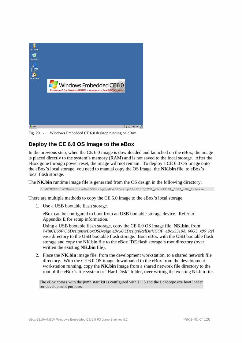
eBox-3310A-MSJK Windows Embedded CE 6.0 R3 Jump Start rev 5.2 Page 45 of 128
Fig. 29 - Windows Embedded CE 6.0 desktop running on eBox
Deploy the CE 6.0 OS Image to the eBox In the previous step, when the CE 6.0 image is downloaded and launched on the eBox, the image is placed directly to the system’s memory (RAM) and is not saved to the local storage. After the eBox gone through power reset, the image will not remain. To deploy a CE 6.0 OS image onto the eBox’s local storage, you need to manual copy the OS image, the NK.bin file, to eBox’s local flash storage.
The NK.bin runtime image file is generated from the OS design in the following directory: C:\WINCE600\OSDesigns\eBoxOSDesign\eBoxOSDesign\Rel Dir\ICOP_eBox3310A_60GS_x86_Release
There are multiple methods to copy the CE 6.0 image to the eBox’s local storage.
1. Use a USB bootable flash storage.
eBox can be configured to boot from an USB bootable storage device. Refer to Appendix E for setup information.
Using a USB bootable flash storage, copy the CE 6.0 OS image file, NK.bin , from \WinCE600\OSDesigns\eBoxOSDesign\eBoxOSDesign\RelDir\ICOP_eBox3310A_60GS_x86_Release directory to the USB bootable flash storage. Boot eBox with the USB bootable flash storage and copy the NK.bin file to the eBox IDE flash storage’s root directory (over written the existing NK.bin file).
2. Place the NK.bin image file, from the development workstation, to a shared network file directory. With the CE 6.0 OS image downloaded to the eBox from the development workstation running, copy the NK.bin image from a shared network file directory to the root of the eBox’s file system or “Hard Disk” folder, over writing the existing Nk.bin file.
The eBox comes with the jump start kit is configured with DOS and the Loadcepc.exe boot loader for development purpose.

eBox-3310A-MSJK Windows Embedded CE 6.0 R3 Jump Start rev 5.2 Page 46 of 128
To deploy CE 6.0 OS runtime image to the target device for distribution, you need to configure the target device’s storage with the appropriate file system and boot loader to launch the runtime image and copy the CE 6.0 OS runtime image to the file system.
The BIOSLoader is provided as part of the public code, including the source code, which you can modify and use as the boot loader for the final product. The BIOSLoader is provided in the following folder:
\WINCE600\Platform\CEPC\SRC\Bootloader\BIOSLoader
When deploying a CE 6.0 device for distribution, you need to use a dedicated boot loader to launch the CE OS runtime image.
The DOS operating system and Loadcepc boot loader, provided as part of this jump start kit, are used for development purpose only and not for distribution.
Unless you are planning to configure the eBox to function in distribution mode, do not configure the eBox’s internal IDE flash storage with BIOSLoader. Doing so will wipe out the existing DOS operating system and preconfigured files.
Once the DOS operating system and preconfigured files are wiped out or damaged, you need to boot eBox to DOS using an USB floppy or USB flash storage and recover the image manually, by formatting the eBox’s internal IDE flash to boot to DOS and copy the original files from the jump start kit CD-ROM.
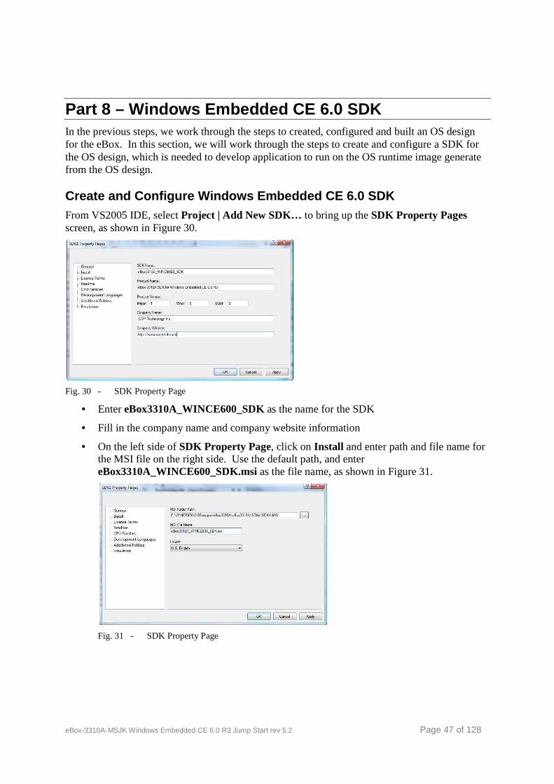
eBox-3310A-MSJK Windows Embedded CE 6.0 R3 Jump Start rev 5.2 Page 47 of 128
Part 8 – Windows Embedded CE 6.0 SDK In the previous steps, we work through the steps to created, configured and built an OS design for the eBox. In this section, we will work through the steps to create and configure a SDK for the OS design, which is needed to develop application to run on the OS runtime image generate from the OS design.
Create and Configure Windows Embedded CE 6.0 SDK From VS2005 IDE, select Project | Add New SDK… to bring up the SDK Property Pages screen, as shown in Figure 30.
Fig. 30 - SDK Property Page
• Enter eBox3310A_WINCE600_SDK as the name for the SDK
• Fill in the company name and company website information
• On the left side of SDK Property Page, click on Install and enter path and file name for the MSI file on the right side. Use the default path, and enter eBox3310A_WINCE600_SDK.msi as the file name, as shown in Figure 31.
Fig. 31 - SDK Property Page
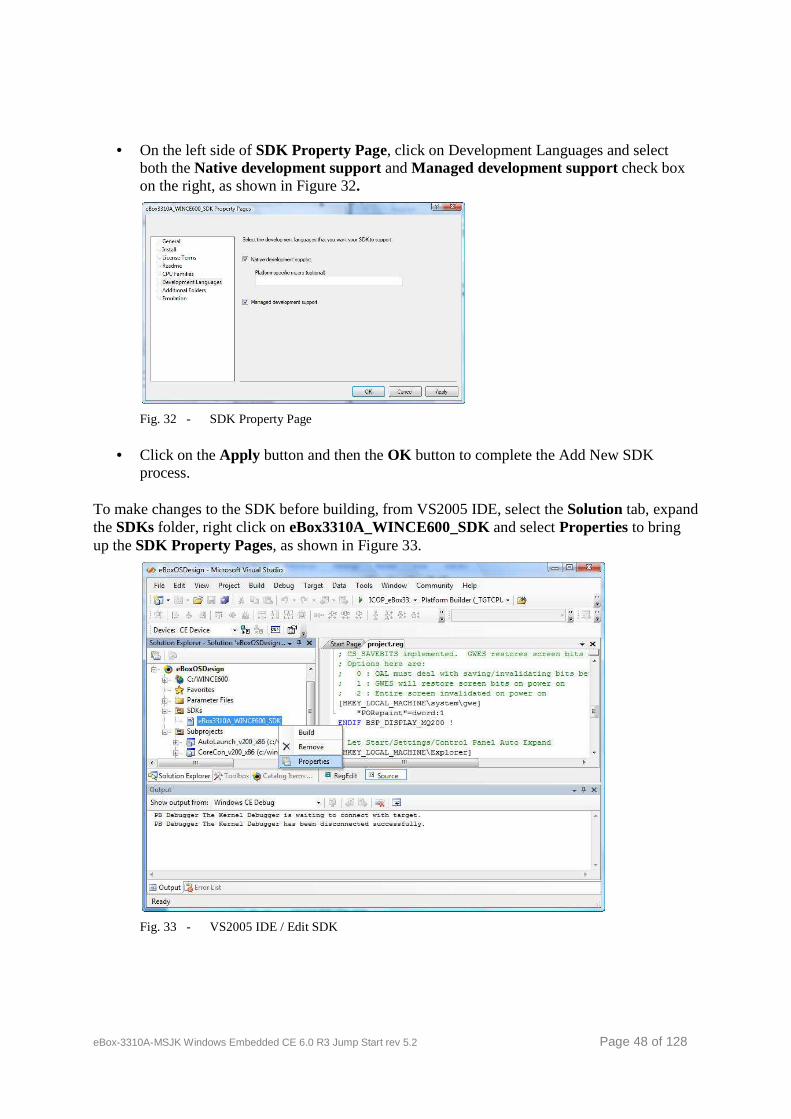
eBox-3310A-MSJK Windows Embedded CE 6.0 R3 Jump Start rev 5.2 Page 48 of 128
• On the left side of SDK Property Page, click on Development Languages and select both the Native development support and Managed development support check box on the right, as shown in Figure 32.
Fig. 32 - SDK Property Page
• Click on the Apply button and then the OK button to complete the Add New SDK process.
To make changes to the SDK before building, from VS2005 IDE, select the Solution tab, expand the SDKs folder, right click on eBox3310A_WINCE600_SDK and select Properties to bring up the SDK Property Pages, as shown in Figure 33.
Fig. 33 - VS2005 IDE / Edit SDK

eBox-3310A-MSJK Windows Embedded CE 6.0 R3 Jump Start rev 5.2 Page 49 of 128
Build Windows Embedded CE 6.0 SDK To build and generate the SDK installation file, select Build | Build All SDKs… from the VS2005 IDE.
It’s possible to build and generate the SDK installation file with the following steps.
• From VS2005 IDE, select the Solution tab, expand the SDKs folder, right click on eBox3310A_WINCE600_SDK and select Build
After the build process is completed, the SDK with the file, eBox3310A_WINCE600_SDK.msi, is generated in the following folder.
\WINCE600\OS Designs\eBoxOSDesign\eBoxOSDesign\SD Ks\SDK1\MSI\
Install this SDK to the Visual Studio development workstation to development CE 6.0 application for the eBox.
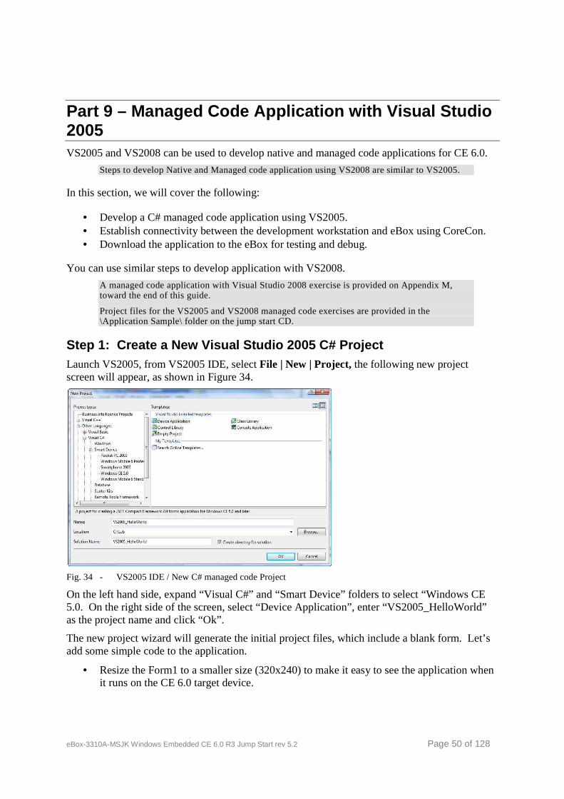
eBox-3310A-MSJK Windows Embedded CE 6.0 R3 Jump Start rev 5.2 Page 50 of 128
Part 9 – Managed Code Application with Visual Studi o 2005 VS2005 and VS2008 can be used to develop native and managed code applications for CE 6.0.
Steps to develop Native and Managed code application using VS2008 are similar to VS2005.
In this section, we will cover the following:
• Develop a C# managed code application using VS2005. • Establish connectivity between the development workstation and eBox using CoreCon. • Download the application to the eBox for testing and debug.
You can use similar steps to develop application with VS2008.
A managed code application with Visual Studio 2008 exercise is provided on Appendix M, toward the end of this guide.
Project files for the VS2005 and VS2008 managed code exercises are provided in the \Application Sample\ folder on the jump start CD.
Step 1: Create a New Visual Studio 2005 C# Project Launch VS2005, from VS2005 IDE, select File | New | Project, the following new project screen will appear, as shown in Figure 34.
Fig. 34 - VS2005 IDE / New C# managed code Project
On the left hand side, expand “Visual C#” and “Smart Device” folders to select “Windows CE 5.0. On the right side of the screen, select “Device Application”, enter “VS2005_HelloWorld” as the project name and click “Ok”.
The new project wizard will generate the initial project files, which include a blank form. Let’s add some simple code to the application.
• Resize the Form1 to a smaller size (320x240) to make it easy to see the application when it runs on the CE 6.0 target device.
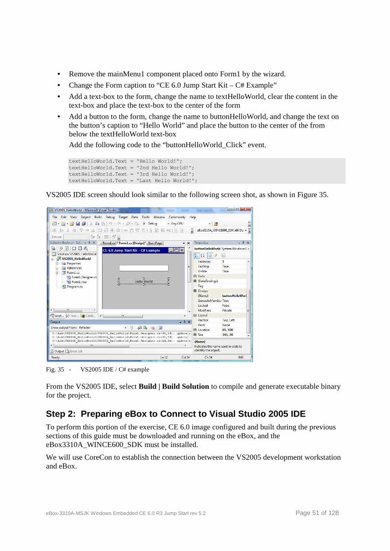
eBox-3310A-MSJK Windows Embedded CE 6.0 R3 Jump Start rev 5.2 Page 51 of 128
• Remove the mainMenu1 component placed onto Form1 by the wizard.
• Change the Form caption to “CE 6.0 Jump Start Kit – C# Example”
• Add a text-box to the form, change the name to textHelloWorld, clear the content in the text-box and place the text-box to the center of the form
• Add a button to the form, change the name to buttonHelloWorld, and change the text on the button’s caption to “Hello World” and place the button to the center of the from below the textHelloWorld text-box
Add the following code to the “buttonHelloWorld_Click” event.
textHelloWorld.Text = "Hello World!"; textHelloWorld.Text = "2nd Hello World!"; textHelloWorld.Text = "3rd Hello World!"; textHelloWorld.Text = "Last Hello World!";
VS2005 IDE screen should look similar to the following screen shot, as shown in Figure 35.
Fig. 35 - VS2005 IDE / C# example
From the VS2005 IDE, select Build | Build Solution to compile and generate executable binary for the project.
Step 2: Preparing eBox to Connect to Visual Studio 2005 IDE To perform this portion of the exercise, CE 6.0 image configured and built during the previous sections of this guide must be downloaded and running on the eBox, and the eBox3310A_WINCE600_SDK must be installed.
We will use CoreCon to establish the connection between the VS2005 development workstation and eBox.
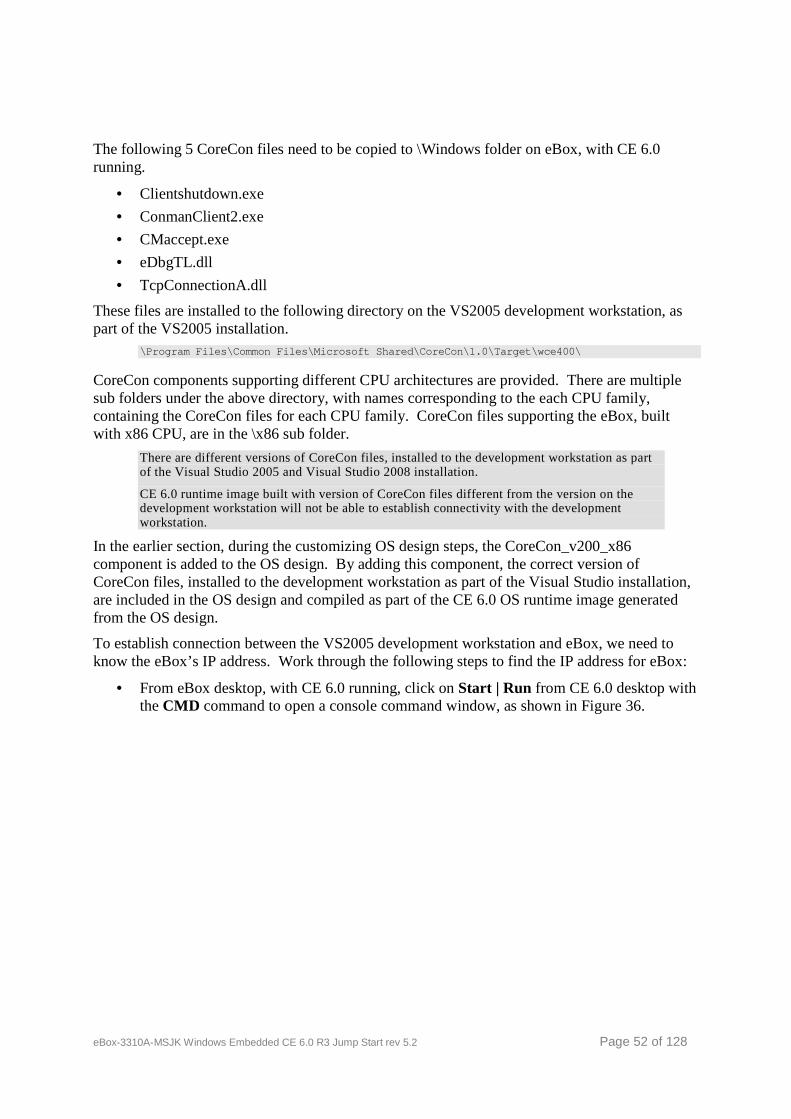
eBox-3310A-MSJK Windows Embedded CE 6.0 R3 Jump Start rev 5.2 Page 52 of 128
The following 5 CoreCon files need to be copied to \Windows folder on eBox, with CE 6.0 running.
• Clientshutdown.exe
• ConmanClient2.exe
• CMaccept.exe
• eDbgTL.dll
• TcpConnectionA.dll
These files are installed to the following directory on the VS2005 development workstation, as part of the VS2005 installation.
\Program Files\Common Files\Microsoft Shared\CoreCo n\1.0\Target\wce400\
CoreCon components supporting different CPU architectures are provided. There are multiple sub folders under the above directory, with names corresponding to the each CPU family, containing the CoreCon files for each CPU family. CoreCon files supporting the eBox, built with x86 CPU, are in the \x86 sub folder.
There are different versions of CoreCon files, installed to the development workstation as part of the Visual Studio 2005 and Visual Studio 2008 installation.
CE 6.0 runtime image built with version of CoreCon files different from the version on the development workstation will not be able to establish connectivity with the development workstation.
In the earlier section, during the customizing OS design steps, the CoreCon_v200_x86 component is added to the OS design. By adding this component, the correct version of CoreCon files, installed to the development workstation as part of the Visual Studio installation, are included in the OS design and compiled as part of the CE 6.0 OS runtime image generated from the OS design.
To establish connection between the VS2005 development workstation and eBox, we need to know the eBox’s IP address. Work through the following steps to find the IP address for eBox:
• From eBox desktop, with CE 6.0 running, click on Start | Run from CE 6.0 desktop with the CMD command to open a console command window, as shown in Figure 36.

eBox-3310A-MSJK Windows Embedded CE 6.0 R3 Jump Start rev 5.2 Page 53 of 128
Fig. 36 - CE 6.0 desktop – Launching the CMD command
• From within the console command window, type IpConfig to show the IP address for the eBox, as shown in Figure 37.
Fig. 37 - CE 6.0 console command window showing the IP address information
Now that we have the IP address for the eBox, let’s move to VS2005 IDE to configure device settings. In order for this to work, both the VS2005 development workstation and eBox must be connected to the same LAN segment and acquire their IP address from the same DHCP server.
From the VS2005 IDE, set the target device to “eBox3310A_WINCE600_SDK x86 Device”, as shown in Figure 38.
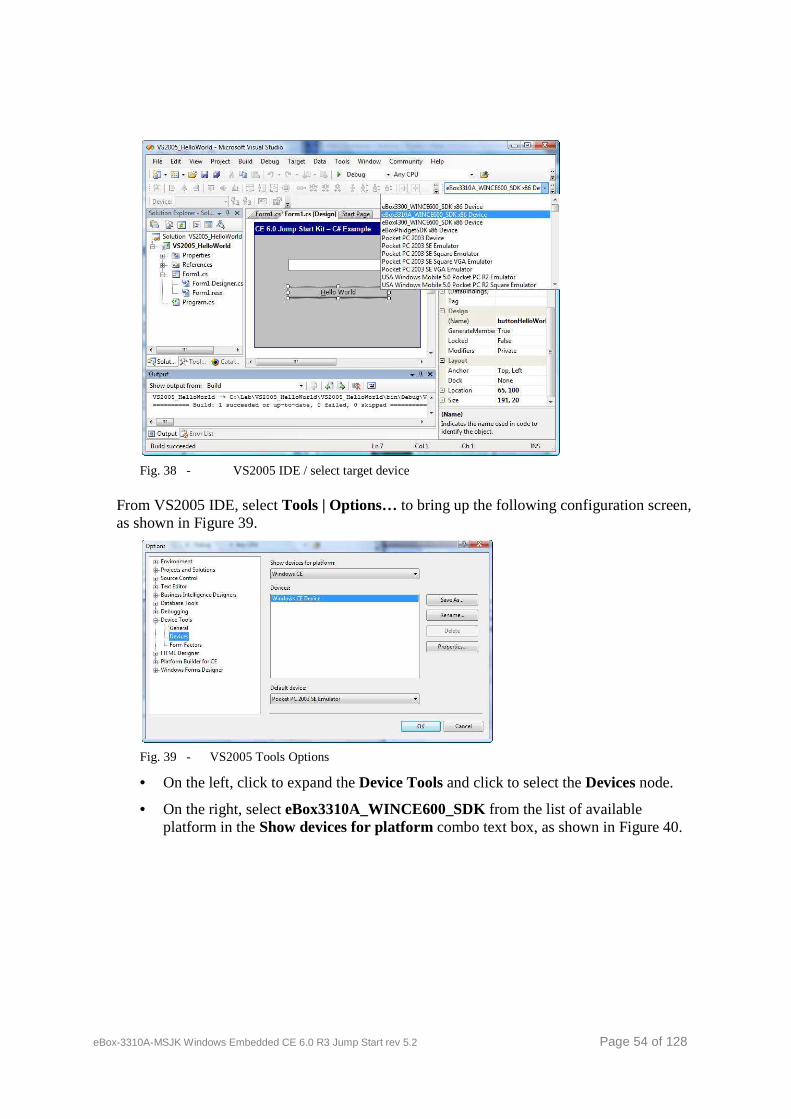
eBox-3310A-MSJK Windows Embedded CE 6.0 R3 Jump Start rev 5.2 Page 54 of 128
Fig. 38 - VS2005 IDE / select target device
From VS2005 IDE, select Tools | Options… to bring up the following configuration screen, as shown in Figure 39.
Fig. 39 - VS2005 Tools Options
• On the left, click to expand the Device Tools and click to select the Devices node.
• On the right, select eBox3310A_WINCE600_SDK from the list of available platform in the Show devices for platform combo text box, as shown in Figure 40.
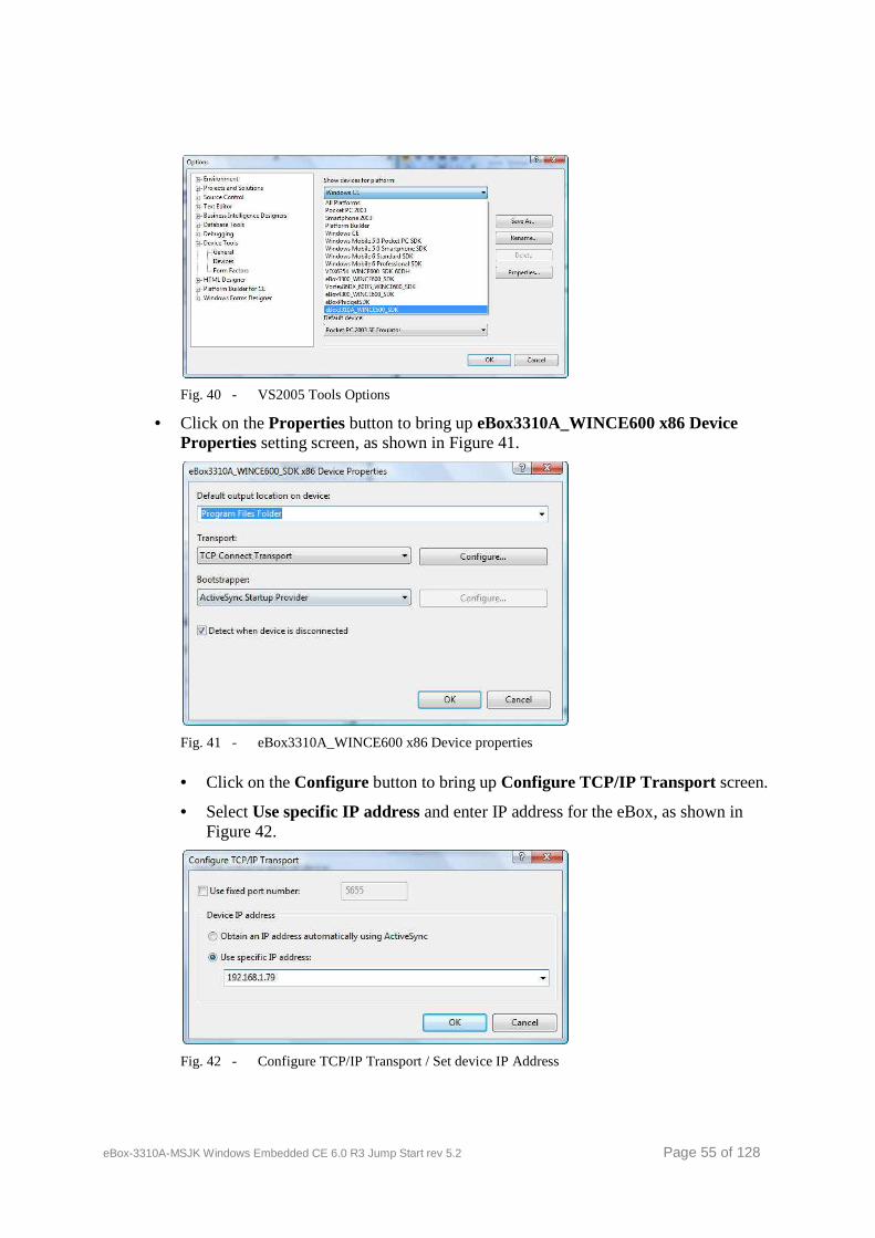
eBox-3310A-MSJK Windows Embedded CE 6.0 R3 Jump Start rev 5.2 Page 55 of 128
Fig. 40 - VS2005 Tools Options
• Click on the Properties button to bring up eBox3310A_WINCE600 x86 Device Properties setting screen, as shown in Figure 41.
Fig. 41 - eBox3310A_WINCE600 x86 Device properties
• Click on the Configure button to bring up Configure TCP/IP Transport screen.
• Select Use specific IP address and enter IP address for the eBox, as shown in Figure 42.
Fig. 42 - Configure TCP/IP Transport / Set device IP Address
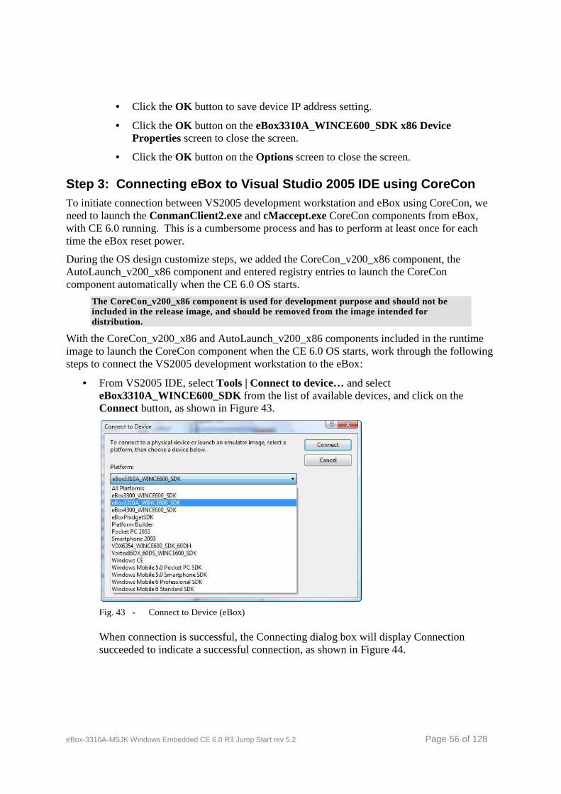
eBox-3310A-MSJK Windows Embedded CE 6.0 R3 Jump Start rev 5.2 Page 56 of 128
• Click the OK button to save device IP address setting.
• Click the OK button on the eBox3310A_WINCE600_SDK x86 Device Properties screen to close the screen.
• Click the OK button on the Options screen to close the screen.
Step 3: Connecting eBox to Visual Studio 2005 IDE using CoreCon To initiate connection between VS2005 development workstation and eBox using CoreCon, we need to launch the ConmanClient2.exe and cMaccept.exe CoreCon components from eBox, with CE 6.0 running. This is a cumbersome process and has to perform at least once for each time the eBox reset power.
During the OS design customize steps, we added the CoreCon_v200_x86 component, the AutoLaunch_v200_x86 component and entered registry entries to launch the CoreCon component automatically when the CE 6.0 OS starts.
The CoreCon_v200_x86 component is used for development purpose and should not be included in the release image, and should be removed from the image intended for distribution.
With the CoreCon_v200_x86 and AutoLaunch_v200_x86 components included in the runtime image to launch the CoreCon component when the CE 6.0 OS starts, work through the following steps to connect the VS2005 development workstation to the eBox:
• From VS2005 IDE, select Tools | Connect to device… and select eBox3310A_WINCE600_SDK from the list of available devices, and click on the Connect button, as shown in Figure 43.
Fig. 43 - Connect to Device (eBox)
When connection is successful, the Connecting dialog box will display Connection succeeded to indicate a successful connection, as shown in Figure 44.
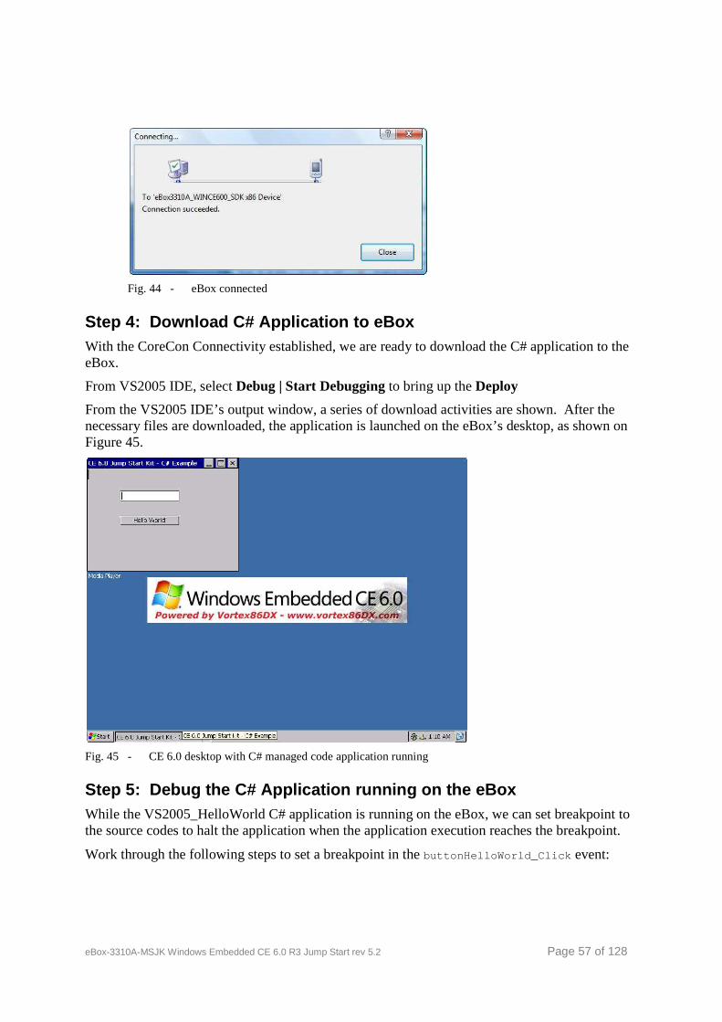
eBox-3310A-MSJK Windows Embedded CE 6.0 R3 Jump Start rev 5.2 Page 57 of 128
Fig. 44 - eBox connected
Step 4: Download C# Application to eBox With the CoreCon Connectivity established, we are ready to download the C# application to the eBox.
From VS2005 IDE, select Debug | Start Debugging to bring up the Deploy
From the VS2005 IDE’s output window, a series of download activities are shown. After the necessary files are downloaded, the application is launched on the eBox’s desktop, as shown on Figure 45.
Fig. 45 - CE 6.0 desktop with C# managed code application running
Step 5: Debug the C# Application running on the eB ox While the VS2005_HelloWorld C# application is running on the eBox, we can set breakpoint to the source codes to halt the application when the application execution reaches the breakpoint.
Work through the following steps to set a breakpoint in the buttonHelloWorld_Click event:
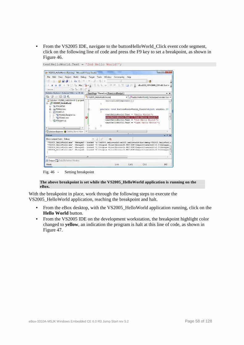
eBox-3310A-MSJK Windows Embedded CE 6.0 R3 Jump Start rev 5.2 Page 58 of 128
• From the VS2005 IDE, navigate to the buttonHelloWorld_Click event code segment, click on the following line of code and press the F9 key to set a breakpoint, as shown in Figure 46. textHelloWorld.Text = "2nd Hello World!" ;
Fig. 46 - Setting breakpoint
The above breakpoint is set while the VS2005_HelloWorld application is running on the eBox.
With the breakpoint in place, work through the following steps to execute the VS2005_HelloWorld application, reaching the breakpoint and halt.
• From the eBox desktop, with the VS2005_HelloWorld application running, click on the Hello World button.
• From the VS2005 IDE on the development workstation, the breakpoint highlight color changed to yellow, an indication the program is halt at this line of code, as shown in Figure 47.
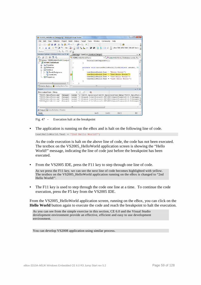
eBox-3310A-MSJK Windows Embedded CE 6.0 R3 Jump Start rev 5.2 Page 59 of 128
Fig. 47 - Execution halt at the breakpoint
• The application is running on the eBox and is halt on the following line of code. textHelloWorld.Text = "2nd Hello World!" ;
As the code execution is halt on the above line of code, the code has not been executed. The textbox on the VS2005_HelloWorld application screen is showing the “Hello World!” message, indicating the line of code just before the breakpoint has been executed.
• From the VS2005 IDE, press the F11 key to step through one line of code.
As we press the F11 key, we can see the next line of code becomes highlighted with yellow. The textbox on the VS2005_HelloWorld application running on the eBox is changed to “2nd Hello World!”.
• The F11 key is used to step through the code one line at a time. To continue the code execution, press the F5 key from the VS2005 IDE.
From the VS2005_HelloWorld application screen, running on the eBox, you can click on the Hello World button again to execute the code and reach the breakpoint to halt the execution.
As you can see from the simple exercise in this section, CE 6.0 and the Visual Studio development environment provide an effective, efficient and easy to use development environment.
You can develop VS2008 application using similar process.
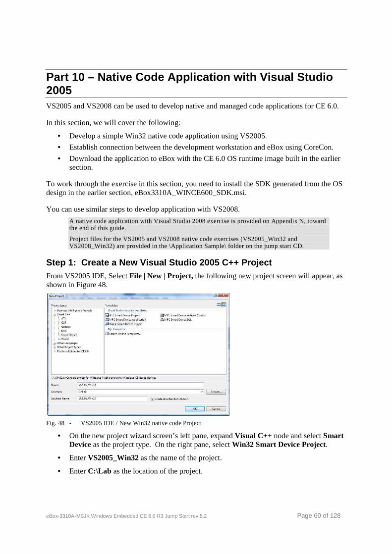
eBox-3310A-MSJK Windows Embedded CE 6.0 R3 Jump Start rev 5.2 Page 60 of 128
Part 10 – Native Code Application with Visual Studi o 2005 VS2005 and VS2008 can be used to develop native and managed code applications for CE 6.0.
In this section, we will cover the following:
• Develop a simple Win32 native code application using VS2005.
• Establish connection between the development workstation and eBox using CoreCon.
• Download the application to eBox with the CE 6.0 OS runtime image built in the earlier section.
To work through the exercise in this section, you need to install the SDK generated from the OS design in the earlier section, eBox3310A_WINCE600_SDK.msi.
You can use similar steps to develop application with VS2008.
A native code application with Visual Studio 2008 exercise is provided on Appendix N, toward the end of this guide.
Project files for the VS2005 and VS2008 native code exercises (VS2005_Win32 and VS2008_Win32) are provided in the \Application Sample\ folder on the jump start CD.
Step 1: Create a New Visual Studio 2005 C++ Projec t From VS2005 IDE, Select File | New | Project, the following new project screen will appear, as shown in Figure 48.
Fig. 48 - VS2005 IDE / New Win32 native code Project
• On the new project wizard screen’s left pane, expand Visual C++ node and select Smart Device as the project type. On the right pane, select Win32 Smart Device Project.
• Enter VS2005_Win32 as the name of the project.
• Enter C:\Lab as the location of the project.
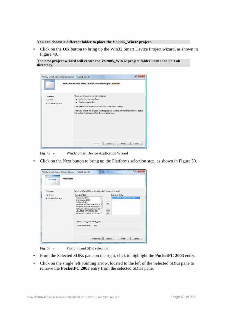
eBox-3310A-MSJK Windows Embedded CE 6.0 R3 Jump Start rev 5.2 Page 61 of 128
You can choose a different folder to place the VS2005_Win32 project.
• Click on the OK button to bring up the Win32 Smart Device Project wizard, as shown in Figure 49.
The new project wizard will create the VS2005_Win32 project folder under the C:\Lab directory.
Fig. 49 - Win32 Smart Device Application Wizard
• Click on the Next button to bring up the Platforms selection step, as shown in Figure 50.
Fig. 50 - Platform and SDK selection
• From the Selected SDKs pane on the right, click to highlight the PocketPC 2003 entry.
• Click on the single left pointing arrow, located to the left of the Selected SDKs pane to remove the PocketPC 2003 entry from the selected SDKs pane.
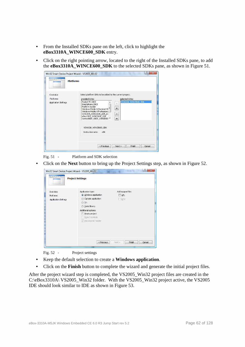
eBox-3310A-MSJK Windows Embedded CE 6.0 R3 Jump Start rev 5.2 Page 62 of 128
• From the Installed SDKs pane on the left, click to highlight the eBox3310A_WINCE600_SDK entry.
• Click on the right pointing arrow, located to the right of the Installed SDKs pane, to add the eBox3310A_WINCE600_SDK to the selected SDKs pane, as shown in Figure 51.
Fig. 51 - Platform and SDK selection
• Click on the Next button to bring up the Project Settings step, as shown in Figure 52.
Fig. 52 - Project settings
• Keep the default selection to create a Windows application.
• Click on the Finish button to complete the wizard and generate the initial project files.
After the project wizard step is completed, the VS2005_Win32 project files are created in the C:\eBox3310A\ VS2005_Win32 folder. With the VS2005_Win32 project active, the VS2005 IDE should look similar to IDE as shown in Figure 53.
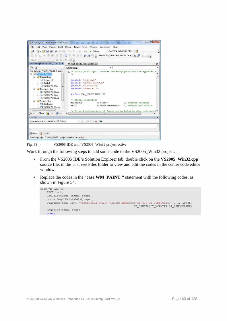
eBox-3310A-MSJK Windows Embedded CE 6.0 R3 Jump Start rev 5.2 Page 63 of 128
Fig. 53 - VS2005 IDE with VS2005_Win32 project active
Work through the following steps to add some code to the VS2005_Win32 project.
• From the VS2005 IDE’s Solution Explorer tab, double click on the VS2005_Win32.cpp source file, in the \Source Files folder to view and edit the codes in the center code editor window.
• Replace the codes in the “case WM_PAINT:” statement with the following codes, as shown in Figure 54. Case WM_PAINT: RECT rect; GetClientRect (hWnd, &rect); hdc = BeginPaint(hWnd, &ps); DrawText(hdc, TEXT( "Vortex86DX-SPARK Windows Embedded CE 6.0 R3 JumpSt art!" ),-1, &rect, DT_CENTER|DT_VCENTER|DT_SINGLELINE); EndPaint(hWnd, &ps); break ;
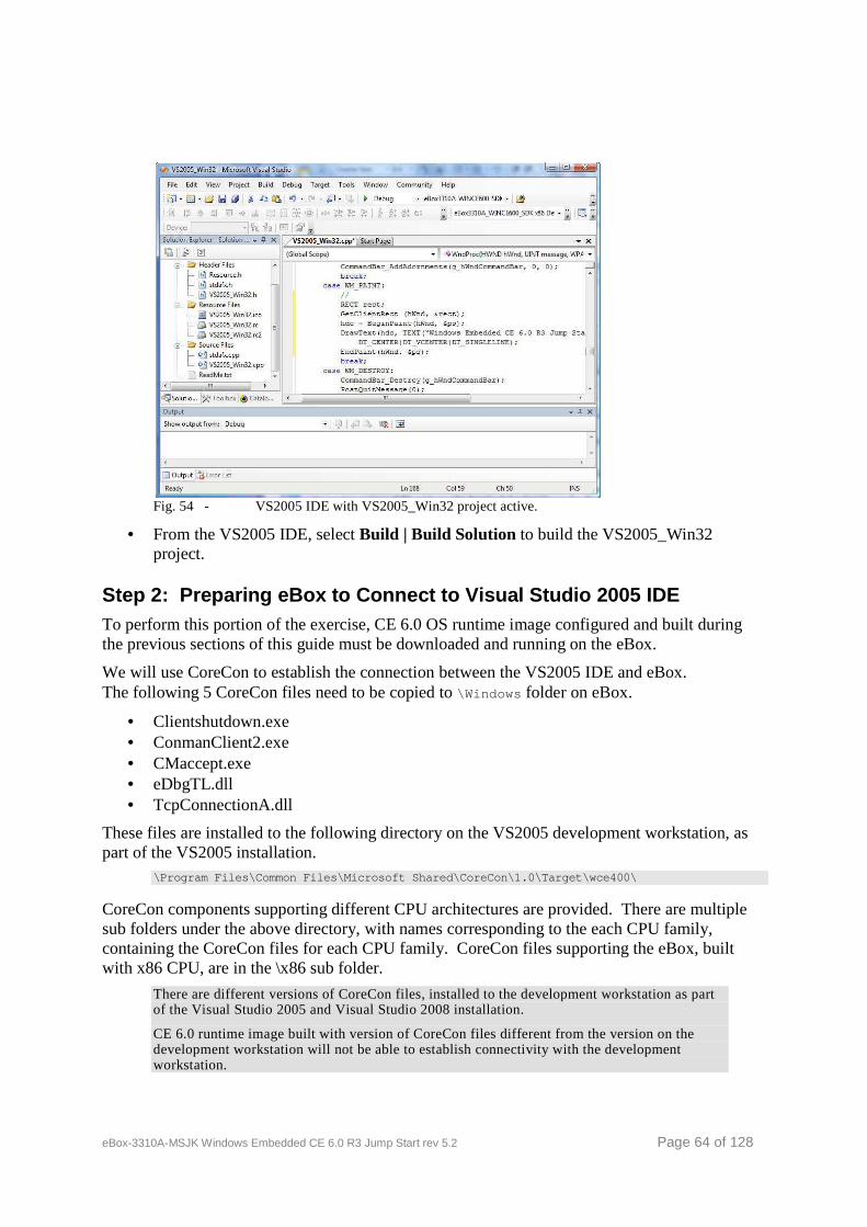
eBox-3310A-MSJK Windows Embedded CE 6.0 R3 Jump Start rev 5.2 Page 64 of 128
Fig. 54 - VS2005 IDE with VS2005_Win32 project active.
• From the VS2005 IDE, select Build | Build Solution to build the VS2005_Win32 project.
Step 2: Preparing eBox to Connect to Visual Studio 2005 IDE To perform this portion of the exercise, CE 6.0 OS runtime image configured and built during the previous sections of this guide must be downloaded and running on the eBox.
We will use CoreCon to establish the connection between the VS2005 IDE and eBox. The following 5 CoreCon files need to be copied to \Windows folder on eBox.
• Clientshutdown.exe • ConmanClient2.exe • CMaccept.exe • eDbgTL.dll • TcpConnectionA.dll
These files are installed to the following directory on the VS2005 development workstation, as part of the VS2005 installation.
\Program Files\Common Files\Microsoft Shared\CoreCo n\1.0\Target\wce400\
CoreCon components supporting different CPU architectures are provided. There are multiple sub folders under the above directory, with names corresponding to the each CPU family, containing the CoreCon files for each CPU family. CoreCon files supporting the eBox, built with x86 CPU, are in the \x86 sub folder.
There are different versions of CoreCon files, installed to the development workstation as part of the Visual Studio 2005 and Visual Studio 2008 installation.
CE 6.0 runtime image built with version of CoreCon files different from the version on the development workstation will not be able to establish connectivity with the development workstation.
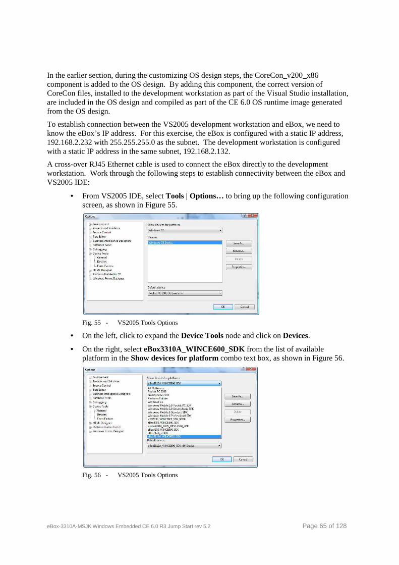
eBox-3310A-MSJK Windows Embedded CE 6.0 R3 Jump Start rev 5.2 Page 65 of 128
In the earlier section, during the customizing OS design steps, the CoreCon_v200_x86 component is added to the OS design. By adding this component, the correct version of CoreCon files, installed to the development workstation as part of the Visual Studio installation, are included in the OS design and compiled as part of the CE 6.0 OS runtime image generated from the OS design.
To establish connection between the VS2005 development workstation and eBox, we need to know the eBox’s IP address. For this exercise, the eBox is configured with a static IP address, 192.168.2.232 with 255.255.255.0 as the subnet. The development workstation is configured with a static IP address in the same subnet, 192.168.2.132.
A cross-over RJ45 Ethernet cable is used to connect the eBox directly to the development workstation. Work through the following steps to establish connectivity between the eBox and VS2005 IDE:
• From VS2005 IDE, select Tools | Options… to bring up the following configuration screen, as shown in Figure 55.
Fig. 55 - VS2005 Tools Options
• On the left, click to expand the Device Tools node and click on Devices.
• On the right, select eBox3310A_WINCE600_SDK from the list of available platform in the Show devices for platform combo text box, as shown in Figure 56.
Fig. 56 - VS2005 Tools Options
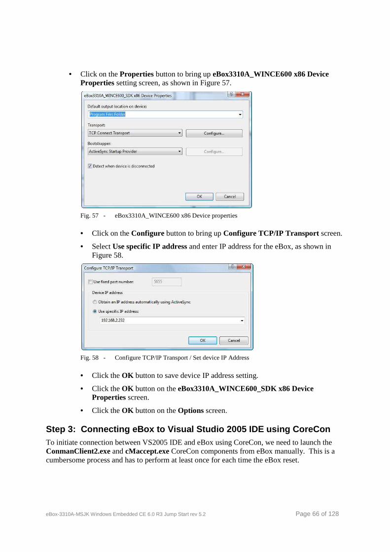
eBox-3310A-MSJK Windows Embedded CE 6.0 R3 Jump Start rev 5.2 Page 66 of 128
• Click on the Properties button to bring up eBox3310A_WINCE600 x86 Device Properties setting screen, as shown in Figure 57.
Fig. 57 - eBox3310A_WINCE600 x86 Device properties
• Click on the Configure button to bring up Configure TCP/IP Transport screen.
• Select Use specific IP address and enter IP address for the eBox, as shown in Figure 58.
Fig. 58 - Configure TCP/IP Transport / Set device IP Address
• Click the OK button to save device IP address setting.
• Click the OK button on the eBox3310A_WINCE600_SDK x86 Device Properties screen.
• Click the OK button on the Options screen.
Step 3: Connecting eBox to Visual Studio 2005 IDE using CoreCon To initiate connection between VS2005 IDE and eBox using CoreCon, we need to launch the ConmanClient2.exe and cMaccept.exe CoreCon components from eBox manually. This is a cumbersome process and has to perform at least once for each time the eBox reset.

eBox-3310A-MSJK Windows Embedded CE 6.0 R3 Jump Start rev 5.2 Page 67 of 128
During the OS design customize steps, we added the CoreCon_v200_x86 component, AutoLaunch_v200_x86 component and entered registry entries to launch the CoreCon component automatically when the CE 6.0 OS starts.
The CoreCon_v200_x86 component is used for development purpose and should not be included in the release image, and should be removed from the image intended for distribution.
With the CoreCon_v200_x86 and AutoLaunch_v200_x86 components included in the runtime image to launch the CoreCon component when the CE 6.0 OS starts, work through the following steps to connect the VS2005 development workstation to the eBox:
• From VS2005 IDE, select Tools | Connect to device… and select eBox3310A_WINCE600_SDK from the list of available devices, and click on the Connect button, as shown in Figure 59.
Fig. 59 - Connect to Device (eBox)
When connection is successful, the Connecting dialog box will display Connection succeeded to indicate a successful connection, as shown in Figure 60.
Fig. 60 - eBox connected
Step 4: Download VS2005_Win32 Application to eBox With the CoreCon Connectivity established, we are ready to download the VS2005_Win32 application to eBox.
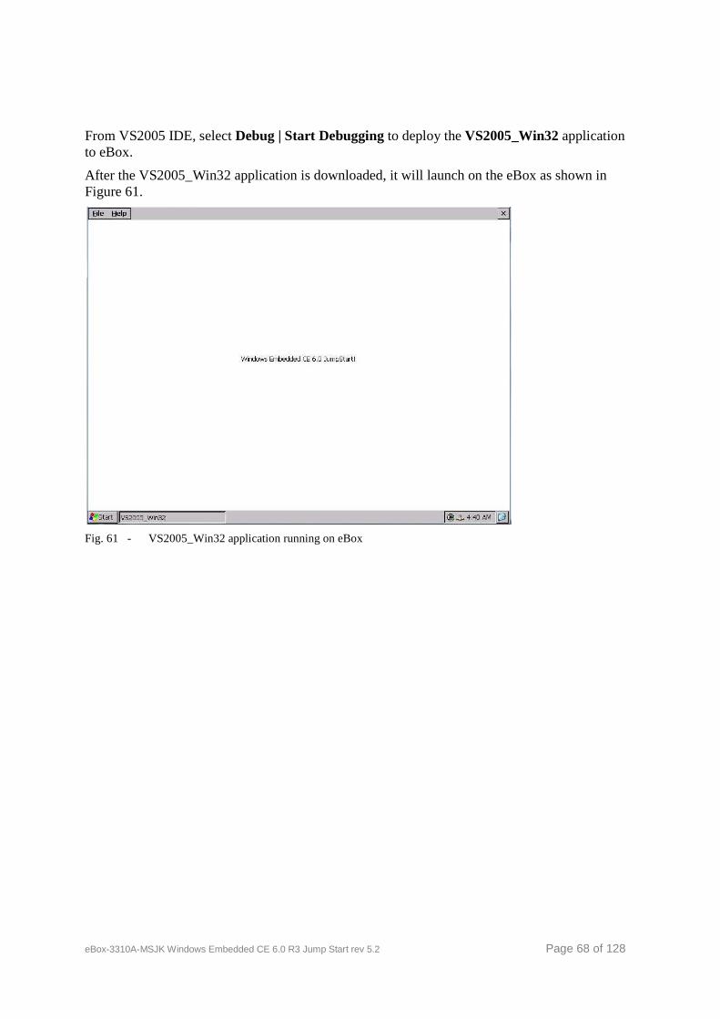
eBox-3310A-MSJK Windows Embedded CE 6.0 R3 Jump Start rev 5.2 Page 68 of 128
From VS2005 IDE, select Debug | Start Debugging to deploy the VS2005_Win32 application to eBox.
After the VS2005_Win32 application is downloaded, it will launch on the eBox as shown in Figure 61.
Fig. 61 - VS2005_Win32 application running on eBox
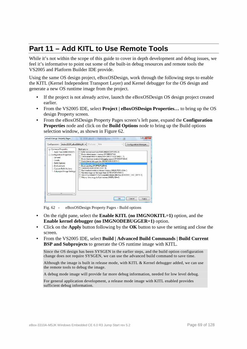
eBox-3310A-MSJK Windows Embedded CE 6.0 R3 Jump Start rev 5.2 Page 69 of 128
Part 11 – Add KITL to Use Remote Tools While it’s not within the scope of this guide to cover in depth development and debug issues, we feel it’s informative to point out some of the built-in debug resources and remote tools the VS2005 and Platform Builder IDE provide.
Using the same OS design project, eBoxOSDesign, work through the following steps to enable the KITL (Kernel Independent Transport Layer) and Kernel debugger for the OS design and generate a new OS runtime image from the project.
• If the project is not already active, launch the eBoxOSDesign OS design project created earlier.
• From the VS2005 IDE, select Project | eBoxOSDesign Properties… to bring up the OS design Property screen.
• From the eBoxOSDesign Property Pages screen’s left pane, expand the Configuration Properties node and click on the Build Options node to bring up the Build options selection window, as shown in Figure 62.
Fig. 62 - eBoxOSDesign Property Pages - Build options
• On the right pane, select the Enable KITL (no IMGNOKITL=1) option, and the Enable kernel debugger (no IMGNODEBUGGER=1) option.
• Click on the Apply button following by the OK button to save the setting and close the screen.
• From the VS2005 IDE, select Build | Advanced Build Commands | Build Current BSP and Subprojects to generate the OS runtime image with KITL.
Since the OS design has been SYSGEN in the earlier steps, and the build option configuration change does not require SYSGEN, we can use the advanced build command to save time.
Although the image is built in release mode, with KITL & Kernel debugger added, we can use the remote tools to debug the image.
A debug mode image will provide far more debug information, needed for low level debug.
For general application development, a release mode image with KITL enabled provides sufficient debug information.
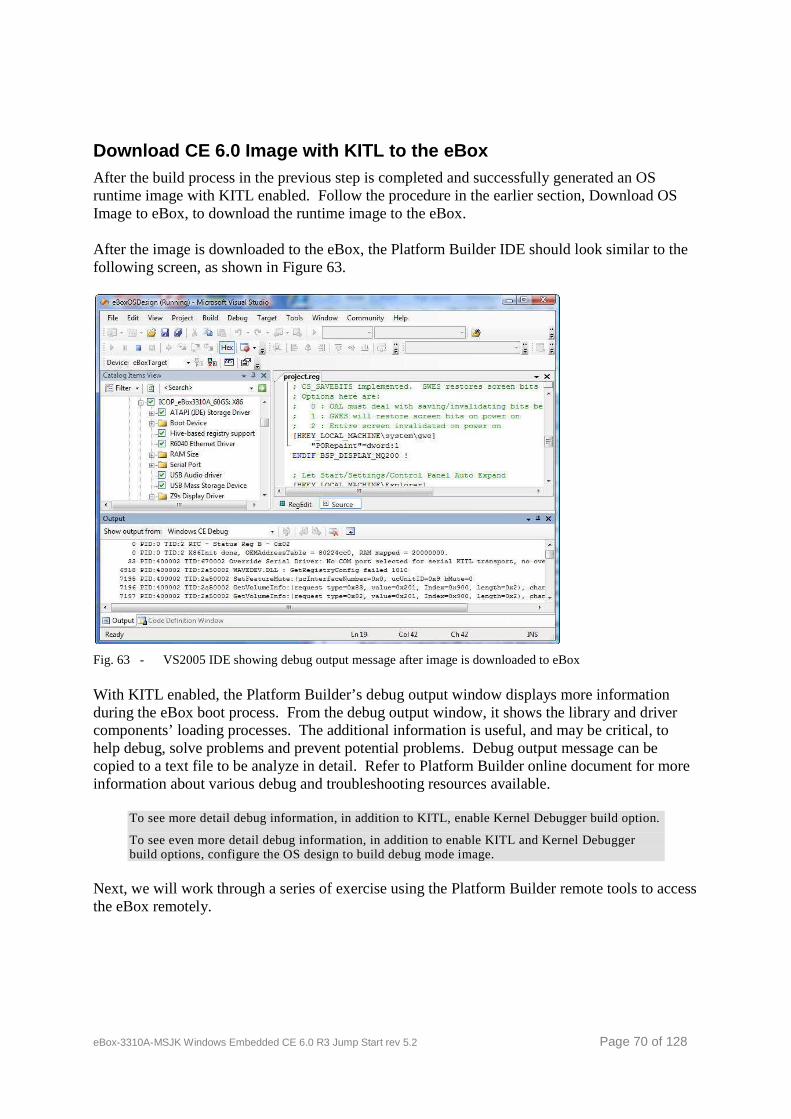
eBox-3310A-MSJK Windows Embedded CE 6.0 R3 Jump Start rev 5.2 Page 70 of 128
Download CE 6.0 Image with KITL to the eBox After the build process in the previous step is completed and successfully generated an OS runtime image with KITL enabled. Follow the procedure in the earlier section, Download OS Image to eBox, to download the runtime image to the eBox.
After the image is downloaded to the eBox, the Platform Builder IDE should look similar to the following screen, as shown in Figure 63.
Fig. 63 - VS2005 IDE showing debug output message after image is downloaded to eBox
With KITL enabled, the Platform Builder’s debug output window displays more information during the eBox boot process. From the debug output window, it shows the library and driver components’ loading processes. The additional information is useful, and may be critical, to help debug, solve problems and prevent potential problems. Debug output message can be copied to a text file to be analyze in detail. Refer to Platform Builder online document for more information about various debug and troubleshooting resources available.
To see more detail debug information, in addition to KITL, enable Kernel Debugger build option.
To see even more detail debug information, in addition to enable KITL and Kernel Debugger build options, configure the OS design to build debug mode image.
Next, we will work through a series of exercise using the Platform Builder remote tools to access the eBox remotely.
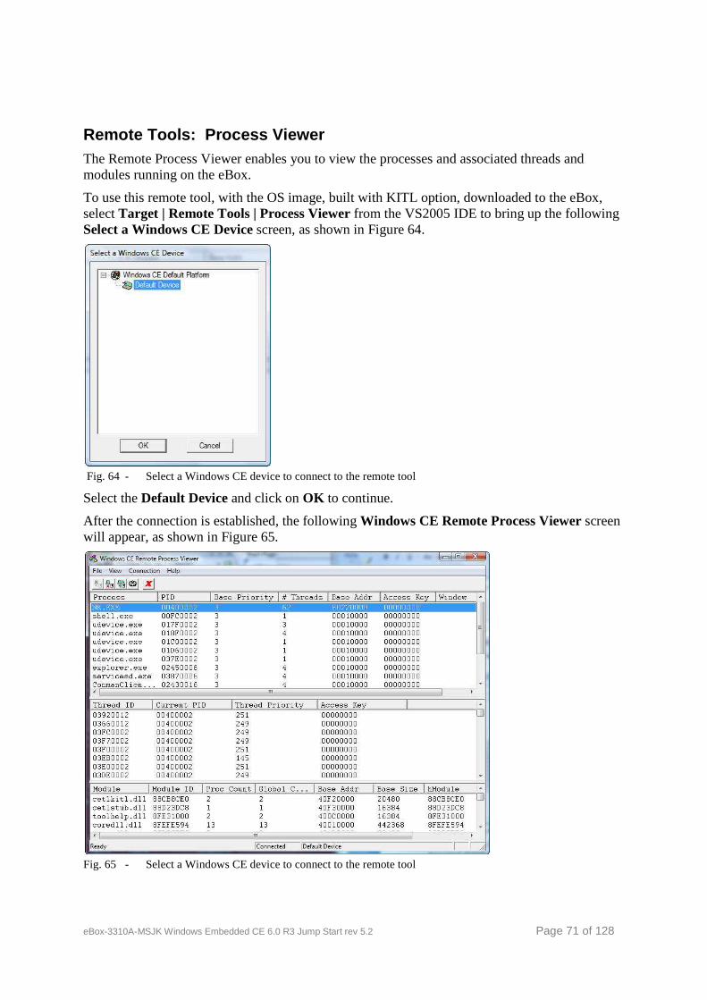
eBox-3310A-MSJK Windows Embedded CE 6.0 R3 Jump Start rev 5.2 Page 71 of 128
Remote Tools: Process Viewer The Remote Process Viewer enables you to view the processes and associated threads and modules running on the eBox.
To use this remote tool, with the OS image, built with KITL option, downloaded to the eBox, select Target | Remote Tools | Process Viewer from the VS2005 IDE to bring up the following Select a Windows CE Device screen, as shown in Figure 64.
Fig. 64 - Select a Windows CE device to connect to the remote tool
Select the Default Device and click on OK to continue.
After the connection is established, the following Windows CE Remote Process Viewer screen will appear, as shown in Figure 65.
Fig. 65 - Select a Windows CE device to connect to the remote tool
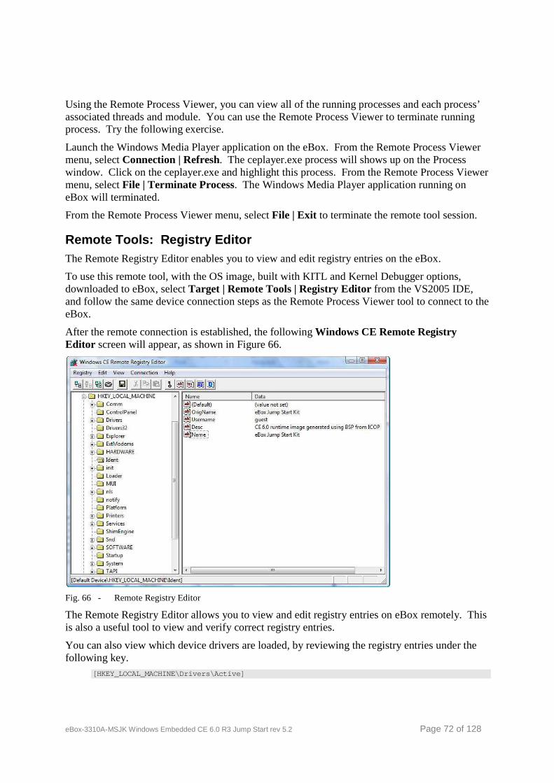
eBox-3310A-MSJK Windows Embedded CE 6.0 R3 Jump Start rev 5.2 Page 72 of 128
Using the Remote Process Viewer, you can view all of the running processes and each process’ associated threads and module. You can use the Remote Process Viewer to terminate running process. Try the following exercise.
Launch the Windows Media Player application on the eBox. From the Remote Process Viewer menu, select Connection | Refresh. The ceplayer.exe process will shows up on the Process window. Click on the ceplayer.exe and highlight this process. From the Remote Process Viewer menu, select File | Terminate Process. The Windows Media Player application running on eBox will terminated.
From the Remote Process Viewer menu, select File | Exit to terminate the remote tool session.
Remote Tools: Registry Editor The Remote Registry Editor enables you to view and edit registry entries on the eBox.
To use this remote tool, with the OS image, built with KITL and Kernel Debugger options, downloaded to eBox, select Target | Remote Tools | Registry Editor from the VS2005 IDE, and follow the same device connection steps as the Remote Process Viewer tool to connect to the eBox.
After the remote connection is established, the following Windows CE Remote Registry Editor screen will appear, as shown in Figure 66.
Fig. 66 - Remote Registry Editor
The Remote Registry Editor allows you to view and edit registry entries on eBox remotely. This is also a useful tool to view and verify correct registry entries.
You can also view which device drivers are loaded, by reviewing the registry entries under the following key.
[HKEY_LOCAL_MACHINE\Drivers\Active]

eBox-3310A-MSJK Windows Embedded CE 6.0 R3 Jump Start rev 5.2 Page 73 of 128
From the Windows CE Remote Registry Editor menu, select Registry | Exit to terminate the Remote Registry Editor tool.
Note: Using similar steps, you can access and try out the other Remote Tools.
eBox-3310A-MSJK Windows Embedded CE 6.0 R3 Jump Start rev 5.2 Page 74 of 128
Summary You have now completed all the steps in this guide. Here’s what we have covered:
• Create an OS design project. • Customize the OS design by adding additional components and modify system registry. • Build a Windows Embedded CE image from the OS design. • Download a Windows Embedded CE image to a target device, the eBox. • Create a C# managed code application using VS2005. • Establish connection between the eBox running CE 6.0 and VS2005 development
workstation using CoreCon. • Deploy C# managed code application from VS2005 and launch on eBox running CE 6.0. • Configure the OS design with KITL enabled to use Remote Tools and debugging. • Access the target device using Remote Tools for debugging.
This is just the beginning. Working on an embedded development project is quite different from developing desktop and enterprise application. Depending on the type of device you are working with, you need to have accurate information about the hardware you are working with and the appropriate BSP and hardware support library.
With the right hardware and Board-Support-Package, the Windows Embedded CE and the Visual Studio development IDE provide an efficient and effective development environment to help simplify difficult development tasks.
Visit the following web sites to learn more about hardware and other Windows Embedded technical resources:
http://www.icoptech.com
http://www.embeddedpc.net
http://www.embedded101.com
eBox-3310A-MSJK Windows Embedded CE 6.0 R3 Jump Start rev 5.2 Page 75 of 128
Congratulations! - You’ve completed all the steps. Here are some of the additional resources to help you gain Windows Embedded CE knowledge. Microsoft Web sites. Windows Embedded CE on MSDN
http://msdn.microsoft.com/en-us/windowsembedded/ce/default.aspx Learn Windows Embedded CE http://msdn.microsoft.com/en-us/windowsembedded/ce/dd367860.aspx Windows Embedded News groups and Community http://msdn.microsoft.com/en-us/windowsembedded/ce/dd424664.aspx To learn more about eBox and other ICOP hardware, visit the following Web sites. http://www.embeddedpc.net http://www.icoptech.com http://www.compactpc.com.tw Or contact ICOP email: [email protected] Phone: (626) 444-6666 Update to this jump start guide and other Windows Embedded CE information resources are available at the following web site: http://www.embeddedpc.net http://www.embeddedpc.net/KnowledgeBase/ Additional information references are available in the Appendixes.
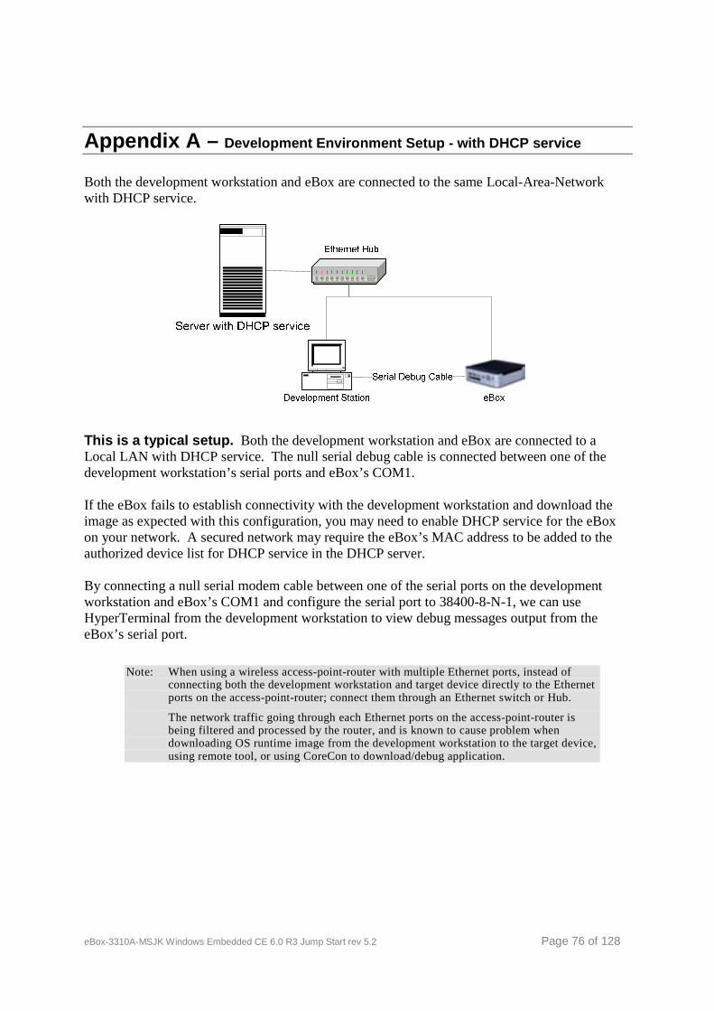
eBox-3310A-MSJK Windows Embedded CE 6.0 R3 Jump Start rev 5.2 Page 76 of 128
Appendix A – Development Environment Setup - with DHCP service
Both the development workstation and eBox are connected to the same Local-Area-Network with DHCP service.
This is a typical setup. Both the development workstation and eBox are connected to a Local LAN with DHCP service. The null serial debug cable is connected between one of the development workstation’s serial ports and eBox’s COM1. If the eBox fails to establish connectivity with the development workstation and download the image as expected with this configuration, you may need to enable DHCP service for the eBox on your network. A secured network may require the eBox’s MAC address to be added to the authorized device list for DHCP service in the DHCP server. By connecting a null serial modem cable between one of the serial ports on the development workstation and eBox’s COM1 and configure the serial port to 38400-8-N-1, we can use HyperTerminal from the development workstation to view debug messages output from the eBox’s serial port.
Note: When using a wireless access-point-router with multiple Ethernet ports, instead of connecting both the development workstation and target device directly to the Ethernet ports on the access-point-router; connect them through an Ethernet switch or Hub.
The network traffic going through each Ethernet ports on the access-point-router is being filtered and processed by the router, and is known to cause problem when downloading OS runtime image from the development workstation to the target device, using remote tool, or using CoreCon to download/debug application.

eBox-3310A-MSJK Windows Embedded CE 6.0 R3 Jump Start rev 5.2 Page 77 of 128
Appendix B – Development Environment Setup – Without DHCP In this setup, eBox is connected directly to the development workstation’s Ethernet port using a Crossover RJ45 Ethernet cable.
When the eBox is connected directly to the development workstation as above, the IP address for the development workstation must be configured correctly for it to work.
When working with this setup, 192.168.2.232 is the preset static IP address for eBox when using the eBox’s preconfigured software, as part of the eBox-3310A-MSJK Windows Embedded CE 6.0 jump start kit.
To download CE 6.0 OS runtime image from the development workstation to eBox, select option 5, “Load OS image from development station with static IP 192.168.2.232”, to trigger the download process.
The prebuilt CE 6.0 OS runtime images provided as part of the preconfigured software on the eBox’s local flash storage are built with DHCP enabled, and will attempt to send request to acquire IP address from an available DHCP server during startup.
When using one of the prebuilt CE 6.0 OS runtime image, to establish CoreCon connectivity between the eBox and development workstation, with static IP addresses, to download application to the eBox, you need to configure the eBox’s static IP address with the intended CE 6.0 OS runtime image running. Refer to Appendix-H for more information about configuring static IP address for CE 6.0.
The development workstation’s IP address must be configured to use a static IP address on the same subnet as the eBox, for this to work. Following is the IP address guideline for the development workstation:
IP address: 192 . 168 . 2 . xxx (where xxx must be different from 232, in used by eBox) Subnet mask: 255 . 255 . 255 . 0
If the IP address is not setup correctly, eBox will not able to communicate with the development workstation.
By connecting a null serial modem cable between one of the serial ports on the development workstation and eBox’s COM1 and configure the serial port to 38400-8-N-1, we can use HyperTerminal from the development workstation to view debug messages output from the eBox’s serial port.
eBox-3310A-MSJK Windows Embedded CE 6.0 R3 Jump Start rev 5.2 Page 78 of 128
Appendix C – Useful information for Windows Embedded CE Windows CE Reference
Windows Embedded CE information resources on MSDN http://msdn.microsoft.com/en-us/windowsembedded/ce/default.aspx This is the main landing page for Windows Embedded CE on MSDN. If you are new to Windows Embedded CE, this site provide valuable information and links to Windows Embedded CE resources.
Windows Embedded Tutorials http://msdn.microsoft.com/en-us/windowsembedded/ce/dd367860.aspx This site provides how-to tutorials on basic and advanced topics about using Windows CE in development of embedded devices.
Windows Embedded News Group http://msdn.microsoft.com/en-us/windowsembedded/ce/dd424664.aspx
Windows Embedded CE Community projects
Open SSH for Windows CE http://www.codeplex.com/wiki/view.aspx?projectname=CESSH Remotely access a Windows CE device in a secure manner using the SSH protocol. It helps execute remote commands on the device, but it also supports tunneling, forwarding arbitrary TCP ports and it can transfer files using the associated SFTP or SCP protocols. Windows CE Wifi Driver for Atheros AR-6000 http://www.codeplex.com/wiki/view.aspx?projectname=CEWifiDriverAR6000 This driver helps connect the Atheros AR-6000 Wifi chipset to your Windows CE device. 32feet.Net – Personal Area Networking for .NET http://www.codeplex.com/32feet 32feet.NET is a project to make personal area networking technologies such as Bluetooth, Infrared (IrDA) and more, easily accessible from .NET code. Requires .NET Compact Framework v1.0 or above and Windows CE.NET 4.2 or above, or .NET Framework v1.1 for desktop Windows XP. Phidgets USB I/O driver shared source projects http://www.codeplex.com/PhidgetsWinCEDriver Phidgets are an easy to use set of building blocks for low cost sensors and controllers. This community project is a driver to allow libraries and applications access to USB Phidgets. Bluetooth Wrapper for Windows CE http://msdn2.microsoft.com/en-us/embedded/aa714519.aspx Provides a free Win32 API Wrapper that developers can expose in Visual Studio .NET or the .NET Compact Framework. Exposing the Win32 API Wrapper reduces the amount of code needed to develop for Bluetooth Technologies and helps make it easier to create compelling Windows Mobile and Windows CE Bluetooth applications. LSP Samples for Windows CE http://www.codeplex.com/LSPSamplesWindowsCE This project provides the code necessary to create LSPs (Layered Service Providers) on Windows CE and Windows Mobile. USB Webcam Driver for Windows CE http://www.codeplex.com/cewebcam
eBox-3310A-MSJK Windows Embedded CE 6.0 R3 Jump Start rev 5.2 Page 79 of 128
This project provides Windows CE device driver to support USB Webcam built to meet the USB video class specification. Windows Embedded CE 6.0 USB Camera Driver http://www.microsoft.com/downloads/details.aspx?FamilyID=2ef087c0-a4ae-42cc-abd0-c466787c11f2&DisplayLang=en This is the URL to the USB camera driver for Windows Embedded CE 6.0 to support USB camera built to the USB video class specification.
Other Useful Links
http://www.embedded101.com
http://www.learningce.com
http://www.embeddedpc.net
Hardware Reference Information
http://www.embeddedpc.net/eBox3310AMSJK The eBox-3310A-MSJK is designed with the Vortex86DX System-On-Chip, with 256MB DDR2 system memory.
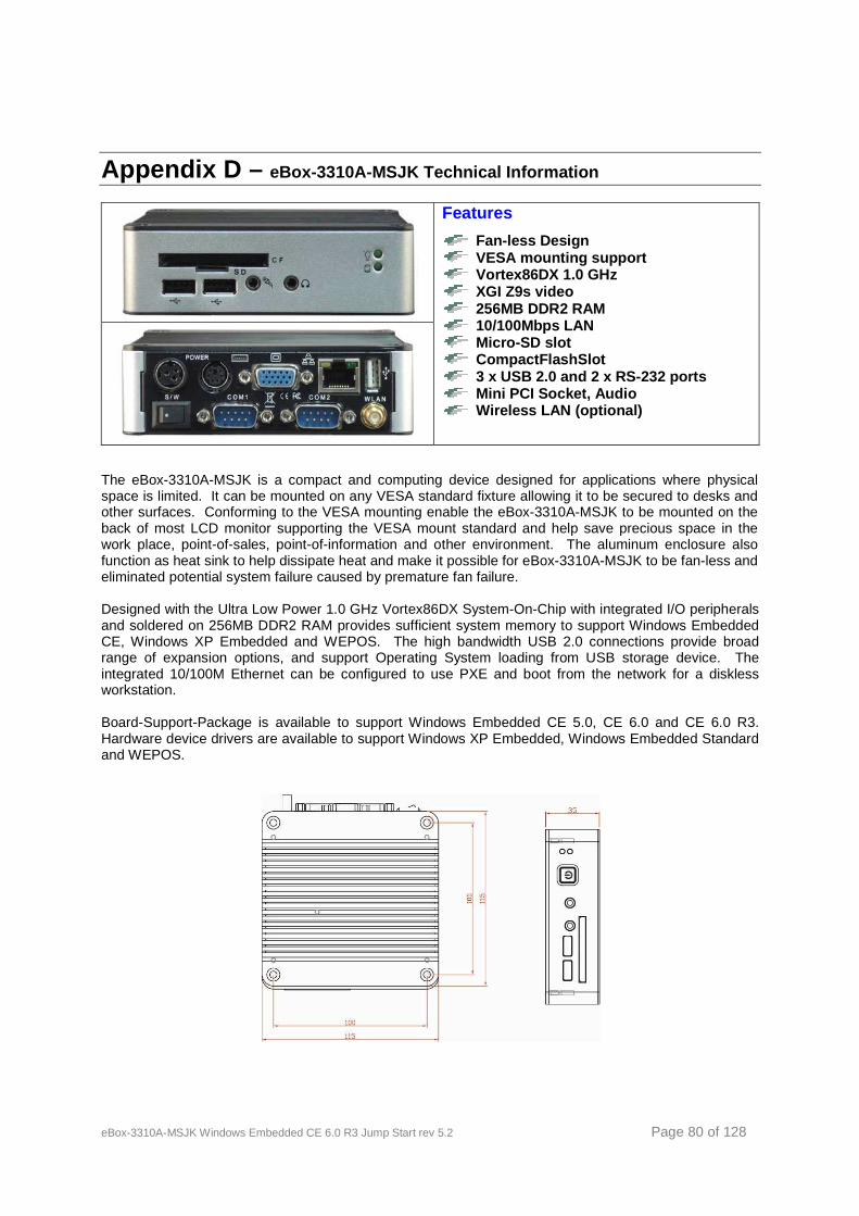
eBox-3310A-MSJK Windows Embedded CE 6.0 R3 Jump Start rev 5.2 Page 80 of 128
Appendix D – eBox-3310A-MSJK Technical Information
Features
Fan-less Design VESA mounting support Vortex86DX 1.0 GHz XGI Z9s video 256MB DDR2 RAM 10/100Mbps LAN Micro-SD slot CompactFlashSlot 3 x USB 2.0 and 2 x RS-232 ports Mini PCI Socket, Audio Wireless LAN (optional)
The eBox-3310A-MSJK is a compact and computing device designed for applications where physical space is limited. It can be mounted on any VESA standard fixture allowing it to be secured to desks and other surfaces. Conforming to the VESA mounting enable the eBox-3310A-MSJK to be mounted on the back of most LCD monitor supporting the VESA mount standard and help save precious space in the work place, point-of-sales, point-of-information and other environment. The aluminum enclosure also function as heat sink to help dissipate heat and make it possible for eBox-3310A-MSJK to be fan-less and eliminated potential system failure caused by premature fan failure.
Designed with the Ultra Low Power 1.0 GHz Vortex86DX System-On-Chip with integrated I/O peripherals and soldered on 256MB DDR2 RAM provides sufficient system memory to support Windows Embedded CE, Windows XP Embedded and WEPOS. The high bandwidth USB 2.0 connections provide broad range of expansion options, and support Operating System loading from USB storage device. The integrated 10/100M Ethernet can be configured to use PXE and boot from the network for a diskless workstation. Board-Support-Package is available to support Windows Embedded CE 5.0, CE 6.0 and CE 6.0 R3. Hardware device drivers are available to support Windows XP Embedded, Windows Embedded Standard and WEPOS.
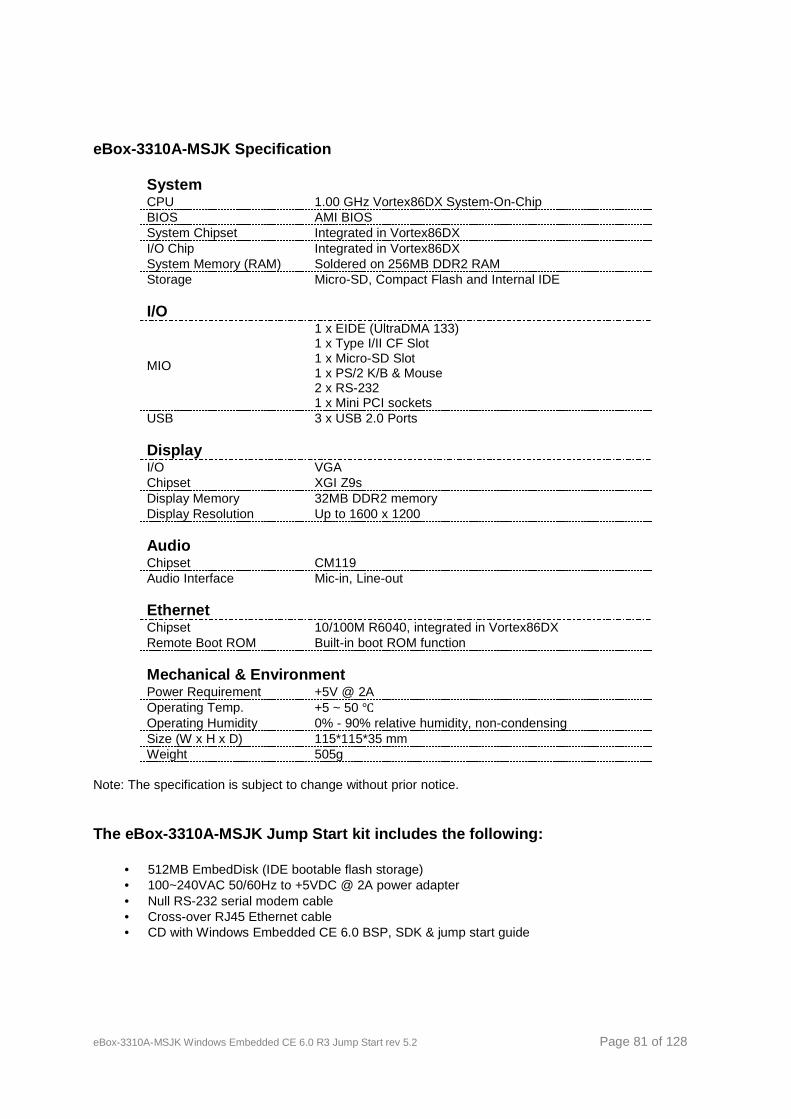
eBox-3310A-MSJK Windows Embedded CE 6.0 R3 Jump Start rev 5.2 Page 81 of 128
eBox-3310A-MSJK Specification
System CPU 1.00 GHz Vortex86DX System-On-Chip BIOS AMI BIOS System Chipset Integrated in Vortex86DX I/O Chip Integrated in Vortex86DX System Memory (RAM) Soldered on 256MB DDR2 RAM Storage Micro-SD, Compact Flash and Internal IDE I/O
MIO
1 x EIDE (UltraDMA 133) 1 x Type I/II CF Slot 1 x Micro-SD Slot 1 x PS/2 K/B & Mouse 2 x RS-232 1 x Mini PCI sockets
USB 3 x USB 2.0 Ports Display I/O VGA Chipset XGI Z9s Display Memory 32MB DDR2 memory Display Resolution Up to 1600 x 1200 Audio Chipset CM119 Audio Interface Mic-in, Line-out Ethernet Chipset 10/100M R6040, integrated in Vortex86DX Remote Boot ROM Built-in boot ROM function Mechanical & Environment Power Requirement +5V @ 2A Operating Temp. +5 ~ 50 ℃ Operating Humidity 0% - 90% relative humidity, non-condensing Size (W x H x D) 115*115*35 mm Weight 505g
Note: The specification is subject to change without prior notice.
The eBox-3310A-MSJK Jump Start kit includes the following:
• 512MB EmbedDisk (IDE bootable flash storage) • 100~240VAC 50/60Hz to +5VDC @ 2A power adapter • Null RS-232 serial modem cable • Cross-over RJ45 Ethernet cable • CD with Windows Embedded CE 6.0 BSP, SDK & jump start guide
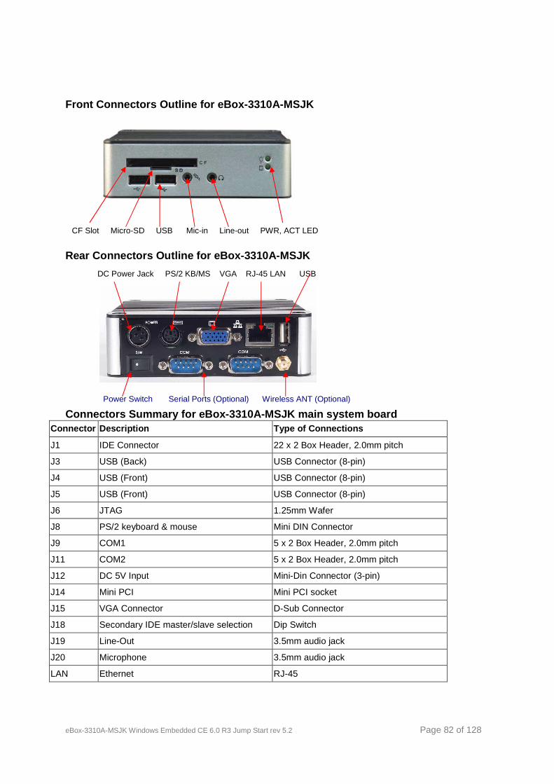
eBox-3310A-MSJK Windows Embedded CE 6.0 R3 Jump Start rev 5.2 Page 82 of 128
Front Connectors Outline for eBox-3310A-MSJK
Rear Connectors Outline for eBox-3310A-MSJK
Connectors Summary for eBox-3310A-MSJK main system board
Connector Description Type of Connections
J1 IDE Connector 22 x 2 Box Header, 2.0mm pitch
J3 USB (Back) USB Connector (8-pin)
J4 USB (Front) USB Connector (8-pin)
J5 USB (Front) USB Connector (8-pin)
J6 JTAG 1.25mm Wafer
J8 PS/2 keyboard & mouse Mini DIN Connector
J9 COM1 5 x 2 Box Header, 2.0mm pitch
J11 COM2 5 x 2 Box Header, 2.0mm pitch
J12 DC 5V Input Mini-Din Connector (3-pin)
J14 Mini PCI Mini PCI socket
J15 VGA Connector D-Sub Connector
J18 Secondary IDE master/slave selection Dip Switch
J19 Line-Out 3.5mm audio jack
J20 Microphone 3.5mm audio jack
LAN Ethernet RJ-45
CF Slot Micro-SD USB Mic-in Line-out PWR, ACT LED
DC Power Jack PS/2 KB/MS VGA RJ-45 LAN USB
Power Switch Serial Ports (Optional) Wireless ANT (Optional)
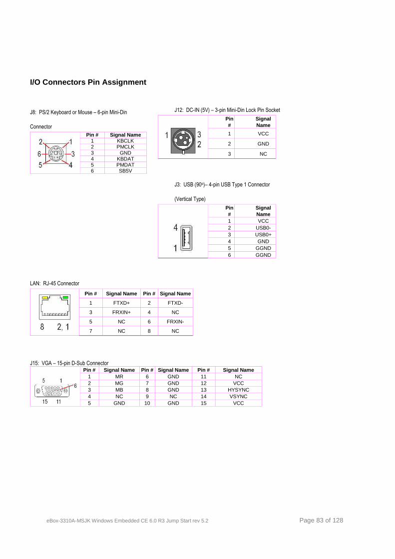
eBox-3310A-MSJK Windows Embedded CE 6.0 R3 Jump Start rev 5.2 Page 83 of 128
I/O Connectors Pin Assignment
J8: PS/2 Keyboard or Mouse – 6-pin Mini-Din
Connector
Pin # Signal Name 1 KBCLK 2 PMCLK 3 GND 4 KBDAT 5 PMDAT 6 SB5V
J12: DC-IN (5V) – 3-pin Mini-Din Lock Pin Socket
Pin #
Signal Name
1 VCC
2 GND
3 NC
J3: USB (90o)– 4-pin USB Type 1 Connector
(Vertical Type)
Pin #
Signal Name
1 VCC 2 USB0- 3 USB0+ 4 GND 5 GGND 6 GGND
LAN: RJ-45 Connector
Pin # Signal Name Pin # Signal Name
1 FTXD+ 2 FTXD-
3 FRXIN+ 4 NC
5 NC 6 FRXIN-
7 NC 8 NC
J15: VGA – 15-pin D-Sub Connector
Pin # Signal Name Pin # Signal Name Pin # Signal Name 1 MR 6 GND 11 NC 2 MG 7 GND 12 VCC 3 MB 8 GND 13 HYSYNC 4 NC 9 NC 14 VSYNC 5 GND 10 GND 15 VCC
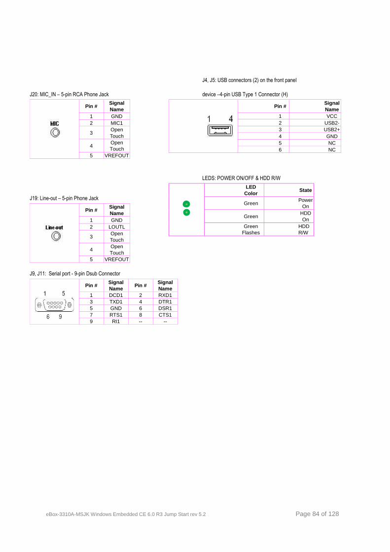
eBox-3310A-MSJK Windows Embedded CE 6.0 R3 Jump Start rev 5.2 Page 84 of 128
J20: MIC_IN – 5-pin RCA Phone Jack
Pin # Signal Name
1 GND 2 MIC1
3 Open Touch
4 Open Touch
5 VREFOUT
J19: Line-out – 5-pin Phone Jack
Pin # Signal Name
1 GND 2 LOUTL
3 Open Touch
4 Open Touch
5 VREFOUT
J4, J5: USB connectors (2) on the front panel
device –4-pin USB Type 1 Connector (H)
Pin # Signal Name
1 VCC 2 USB2- 3 USB2+ 4 GND 5 NC 6 NC
LEDS: POWER ON/OFF & HDD R/W
LED Color
State
Green Power
On
Green HDD On
Green Flashes
HDD R/W
J9, J11: Serial port - 9-pin Dsub Connector
Pin # Signal Name
Pin # Signal Name
1 DCD1 2 RXD1 3 TXD1 4 DTR1 5 GND 6 DSR1 7 RTS1 8 CTS1 9 RI1 -- --
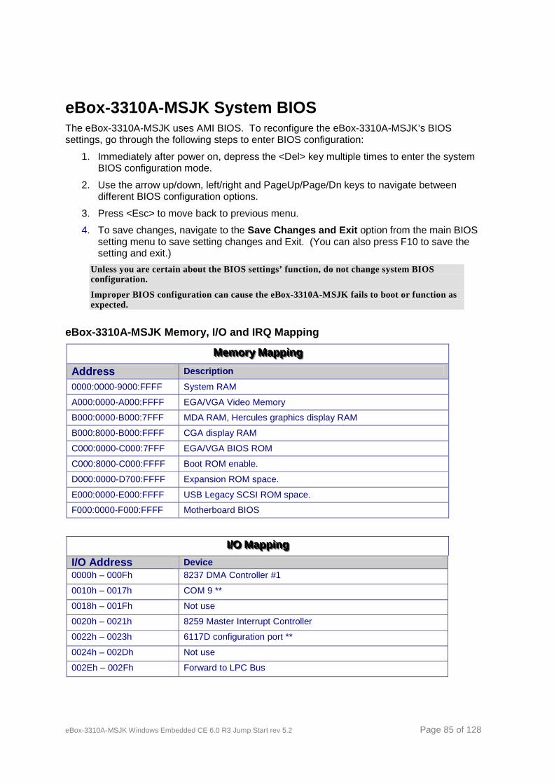
eBox-3310A-MSJK Windows Embedded CE 6.0 R3 Jump Start rev 5.2 Page 85 of 128
eBox-3310A-MSJK System BIOS The eBox-3310A-MSJK uses AMI BIOS. To reconfigure the eBox-3310A-MSJK’s BIOS settings, go through the following steps to enter BIOS configuration:
1. Immediately after power on, depress the <Del> key multiple times to enter the system BIOS configuration mode.
2. Use the arrow up/down, left/right and PageUp/Page/Dn keys to navigate between different BIOS configuration options.
3. Press <Esc> to move back to previous menu.
4. To save changes, navigate to the Save Changes and Exit option from the main BIOS setting menu to save setting changes and Exit. (You can also press F10 to save the setting and exit.)
Unless you are certain about the BIOS settings’ function, do not change system BIOS configuration.
Improper BIOS configuration can cause the eBox-3310A-MSJK fails to boot or function as expected.
eBox-3310A-MSJK Memory, I/O and IRQ Mapping
MMMeeemmmooorrryyy MMMaaappppppiiinnnggg
Address Description 0000:0000-9000:FFFF System RAM A000:0000-A000:FFFF EGA/VGA Video Memory B000:0000-B000:7FFF MDA RAM, Hercules graphics display RAM B000:8000-B000:FFFF CGA display RAM C000:0000-C000:7FFF EGA/VGA BIOS ROM C000:8000-C000:FFFF Boot ROM enable. D000:0000-D700:FFFF Expansion ROM space. E000:0000-E000:FFFF USB Legacy SCSI ROM space. F000:0000-F000:FFFF Motherboard BIOS
III///OOO MMMaaappppppiiinnnggg
I/O Address Device 0000h – 000Fh 8237 DMA Controller #1 0010h – 0017h COM 9 **
0018h – 001Fh Not use
0020h – 0021h 8259 Master Interrupt Controller 0022h – 0023h 6117D configuration port **
0024h – 002Dh Not use
002Eh – 002Fh Forward to LPC Bus
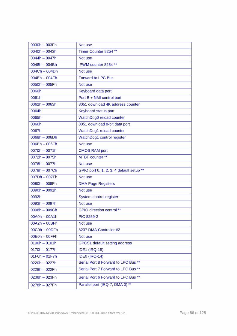
eBox-3310A-MSJK Windows Embedded CE 6.0 R3 Jump Start rev 5.2 Page 86 of 128
0030h – 003Fh Not use
0040h – 0043h Timer Counter 8254 ** 0044h – 0047h Not use
0048h – 004Bh PWM counter 8254 **
004Ch – 004Dh Not use
004Eh – 004Fh Forward to LPC Bus
0050h – 005Fh Not use
0060h Keyboard data port 0061h Port B + NMI control port
0062h – 0063h 8051 download 4K address counter
0064h Keyboard status port
0065h WatchDog0 reload counter
0066h 8051 download 8-bit data port
0067h WatchDog1 reload counter
0068h – 006Dh WatchDog1 control register
006Eh – 006Fh Not use
0070h – 0071h CMOS RAM port
0072h – 0075h MTBF counter **
0076h – 0077h Not use
0078h – 007Ch GPIO port 0, 1, 2, 3, 4 default setup **
007Dh – 007Fh Not use 0080h – 008Fh DMA Page Registers 0090h – 0091h Not use
0092h System control register
0093h – 0097h Not use
0098h – 009Ch GPIO direction control **
00A0h – 00A1h PIC 8259-2 00A2h – 00BFh Not use
00C0h – 00DFh 8237 DMA Controller #2 00E0h – 00FFh Not use
0100h – 0101h GPCS1 default setting address
0170h – 0177h IDE1 (IRQ-15)
01F0h – 01F7h IDE0 (IRQ-14) 0220h – 0227h Serial Port 8 Forward to LPC Bus **
0228h – 022Fh Serial Port 7 Forward to LPC Bus **
0238h – 023Fh Serial Port 6 Forward to LPC Bus **
0278h – 027Fh Parallel port (IRQ-7, DMA 0) **
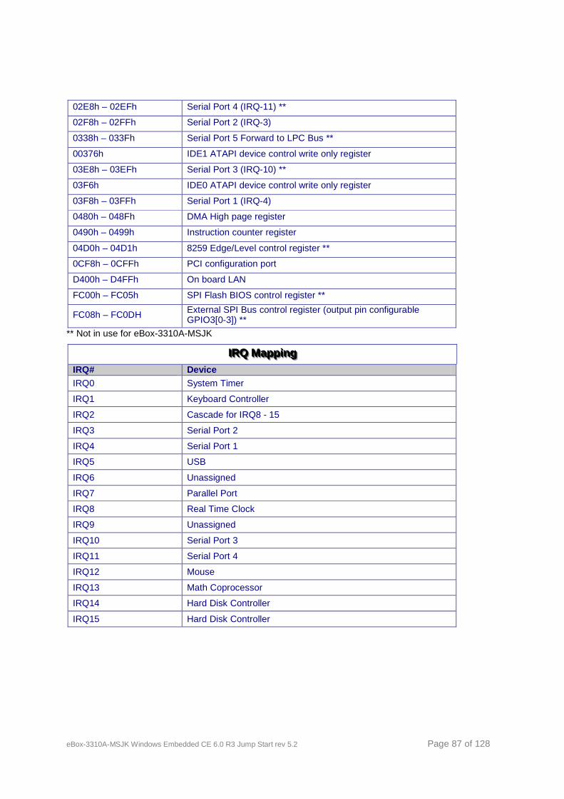
eBox-3310A-MSJK Windows Embedded CE 6.0 R3 Jump Start rev 5.2 Page 87 of 128
02E8h – 02EFh Serial Port 4 (IRQ-11) ** 02F8h – 02FFh Serial Port 2 (IRQ-3) 0338h – 033Fh Serial Port 5 Forward to LPC Bus **
00376h IDE1 ATAPI device control write only register
03E8h – 03EFh Serial Port 3 (IRQ-10) **
03F6h IDE0 ATAPI device control write only register
03F8h – 03FFh Serial Port 1 (IRQ-4) 0480h – 048Fh DMA High page register
0490h – 0499h Instruction counter register
04D0h – 04D1h 8259 Edge/Level control register **
0CF8h – 0CFFh PCI configuration port
D400h – D4FFh On board LAN
FC00h – FC05h SPI Flash BIOS control register **
FC08h – FC0DH External SPI Bus control register (output pin configurable GPIO3[0-3]) **
** Not in use for eBox-3310A-MSJK
IIIRRRQQQ MMMaaappppppiiinnnggg IRQ# Device IRQ0 System Timer
IRQ1 Keyboard Controller
IRQ2 Cascade for IRQ8 - 15
IRQ3 Serial Port 2
IRQ4 Serial Port 1
IRQ5 USB
IRQ6 Unassigned
IRQ7 Parallel Port
IRQ8 Real Time Clock
IRQ9 Unassigned
IRQ10 Serial Port 3
IRQ11 Serial Port 4
IRQ12 Mouse
IRQ13 Math Coprocessor
IRQ14 Hard Disk Controller
IRQ15 Hard Disk Controller

eBox-3310A-MSJK Windows Embedded CE 6.0 R3 Jump Start rev 5.2 Page 88 of 128
Appendix E – eBox Startup Options By changing the BIOS settings, eBox can be configured to boot from the following resources.
• Internal IDE storage
• CompactFlash
• Micro-SD
• USB Floppy
• USB storage
• USB CD/DVD-ROM drive
• Remote Network Boot using PXE
By default, eBox is set to boot from the IDE storage device.
Here are the steps to configure eBox to boot from bootable USB flash storage. The USB flash storage device must be inserted to the eBox’s USB interface prior to power on.
• Configure an USB flash storage to boot to DOS.
USB flash devices from different manufacture are built with different components. Not all USB flash can be configured as bootable device. Refer to the USB flash manufacture’s technical document for information.
• Insert the bootable USB flash storage to one of the eBox’s USB ports, before power on.
• Power on the eBox.
• Press the DEL key multiple times immediately after eBox power on
• From the BIOS Setup Utility menu, use the Left/Right Arrow key to select the “Boot” option
• With the “Boot” option selected, use the Up/Down Arrow key to select “Boot Device Priority”, and press the Enter key
• Use the Up/Down Arrow key to select “1st Boot Device”, and press the Enter key
• From the small Options menu, use the Up/Down Arrow key to select “USB: xxx” (xxx = name of the USB flash storage) and press Enter
• Press the ESC key to navigate back to the main menu
• Use the Left/Right Arrow key to select “Exit”
• Use the Up/Down Arrow key to select “Save Changes and Exit” to complete the BIOS configuration
Consult eBox manual for more information about BIOS settings.
When creating a bootable USB flash storage device, it’s common to use DOS as the operating system. The DOS operating system supports FAT file system and can only address storage partition that is 2 GB or smaller.
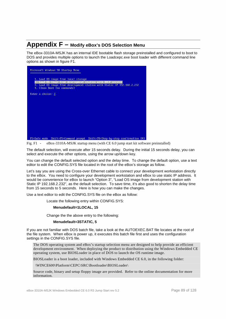
eBox-3310A-MSJK Windows Embedded CE 6.0 R3 Jump Start rev 5.2 Page 89 of 128
Appendix F – Modify eBox’s DOS Selection Menu The eBox-3310A-MSJK has an internal IDE bootable flash storage preinstalled and configured to boot to DOS and provides multiple options to launch the Loadcepc.exe boot loader with different command line options as shown in figure F1.
Fig. F1 - eBox-3310A-MSJK startup menu (with CE 6.0 jump start kit software preinstalled)
The default selection, will execute after 15 seconds delay. During the initial 15 seconds delay, you can select and execute the other options, using the arrow up/down key.
You can change the default selected option and the delay time. To change the default option, use a text editor to edit the CONFIG.SYS file located in the root of the eBox’s storage as follow.
Let’s say you are using the Cross-over Ethernet cable to connect your development workstation directly to the eBox. You need to configure your development workstation and eBox to use static IP address. It would be convenience for eBox to launch “Option 3”, “Load OS image from development station with Static IP 192.168.2.232”, as the default selection. To save time, it’s also good to shorten the delay time from 15 seconds to 5 seconds. Here is how you can make the changes.
Use a text editor to edit the CONFIG.SYS file on the eBox as follow:
Locate the following entry within CONFIG.SYS:
Menudefault=1LOCAL, 15
Change the the above entry to the following:
Menudefault=3STATIC, 5
If you are not familiar with DOS batch file, take a look at the AUTOEXEC.BAT file locates at the root of the file system. When eBox is power up, it executes this batch file first and uses the configuration settings in the CONFIG.SYS file.
The DOS operating system and eBox’s startup selection menu are designed to help provide an efficient development environment. When deploying the product to distribution using the Windows Embedded CE operating system, use BIOSLoader in place of DOS to launch the OS runtime image.
BIOSLoader is a boot loader, included with Windows Embedded CE 6.0, in the following folder:
\WINCE600\Platform\CEPC\SRC\Bootloader\BIOSLoader\
Source code, binary and setup floppy image are provided. Refer to the online documentation for more information.
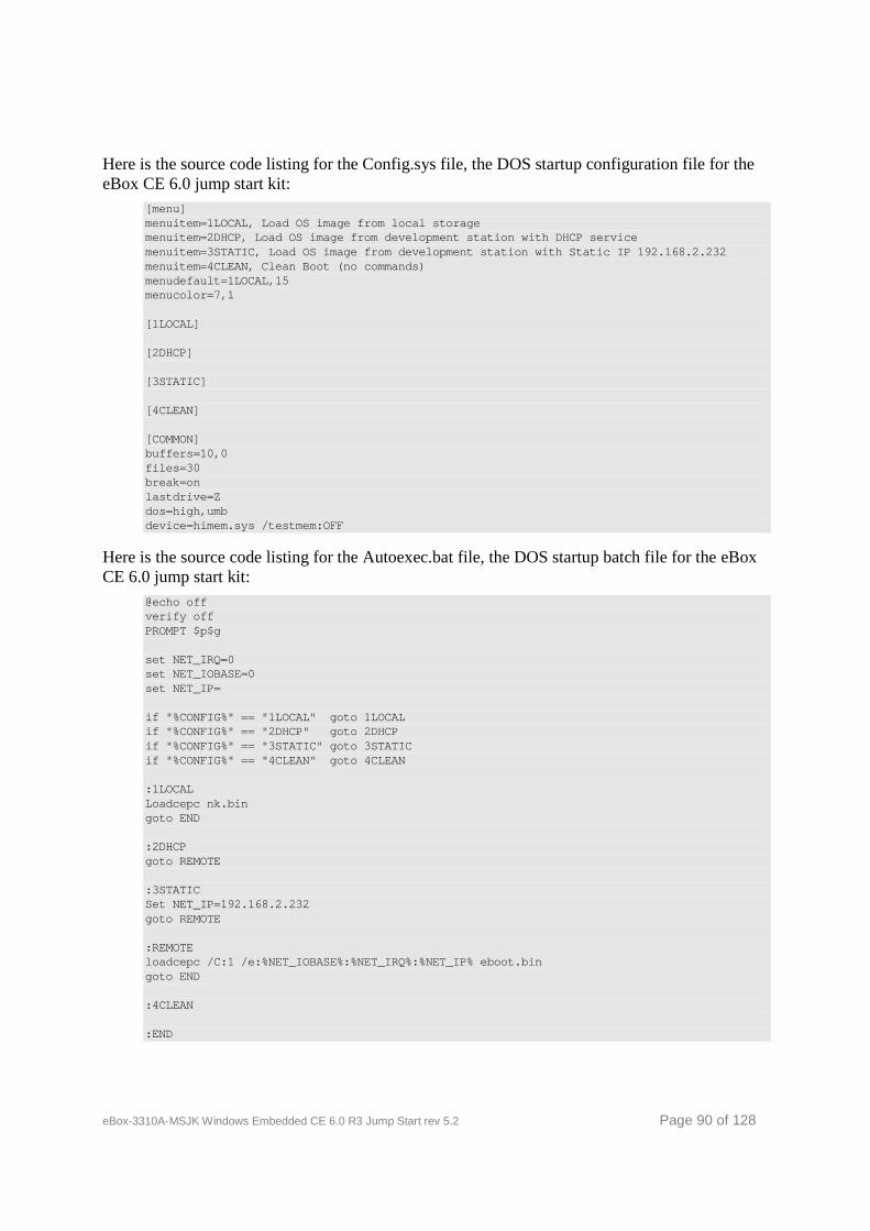
eBox-3310A-MSJK Windows Embedded CE 6.0 R3 Jump Start rev 5.2 Page 90 of 128
Here is the source code listing for the Config.sys file, the DOS startup configuration file for the eBox CE 6.0 jump start kit:
[menu] menuitem=1LOCAL, Load OS image from local storage menuitem=2DHCP, Load OS image from development stat ion with DHCP service menuitem=3STATIC, Load OS image from development st ation with Static IP 192.168.2.232 menuitem=4CLEAN, Clean Boot (no commands) menudefault=1LOCAL,15 menucolor=7,1 [1LOCAL] [2DHCP] [3STATIC] [4CLEAN] [COMMON] buffers=10,0 files=30 break=on lastdrive=Z dos=high,umb device=himem.sys /testmem:OFF
Here is the source code listing for the Autoexec.bat file, the DOS startup batch file for the eBox CE 6.0 jump start kit:
@echo off verify off PROMPT $p$g set NET_IRQ=0 set NET_IOBASE=0 set NET_IP= if "%CONFIG%" == "1LOCAL" goto 1LOCAL if "%CONFIG%" == "2DHCP" goto 2DHCP if "%CONFIG%" == "3STATIC" goto 3STATIC if "%CONFIG%" == "4CLEAN" goto 4CLEAN :1LOCAL Loadcepc nk.bin goto END :2DHCP goto REMOTE :3STATIC Set NET_IP=192.168.2.232 goto REMOTE :REMOTE loadcepc /C:1 /e:%NET_IOBASE%:%NET_IRQ%:%NET_IP% eb oot.bin goto END :4CLEAN :END
eBox-3310A-MSJK Windows Embedded CE 6.0 R3 Jump Start rev 5.2 Page 91 of 128
Appendix G – Debug Serial Port
Windows Embedded CE captures the first Serial port and uses it to output debug messages. Since much of the debug messages are available with the use of KITL via an Ethernet connection.
When using one of the preconfigured options to load the CE OS runtime image from the local storage, the Loadcepc is executed with command line parameter as follow:
Loadcepc NK.bin
The NK.bin file is the Windows Embedded CE OS runtime image. To configure COM1 to send out serial debug messages, change the above line of code to the following:
Loadcepc /C:1 NK.bin
When using one of the preconfigured options to send bootme request and download the runtime image from the development workstation, the Loadcepc is executed with command line parameter as follow:
Loadcepc /C:1 /e:%NET_IOBASE%:%NET_IRQ%:%NET_IP% EB OOT.bin
The EBOOT.bin file is an Ethernet boot loader, needed to request and process the function to download OS runtime images from the Platform Builder development workstation.
The NET_IOBASE and NET_IRQ parameters are needed by the older legacy networking hardware and is no longer needed by the newer generation hardware.
To send request to download runtime image from the development workstation using static IP (192.168.2.232) and configure the device to send serial debug messages via COM2, launch the Loadcepc executable with command parameters as follow:
Loadcepc /C:2 /e:0:0:192.168.2.232 EBOOT.bin
To access help information for the Loadcepc loader, launch the Loadcepc executable with the command parameters as follow:
Loadcepc /?
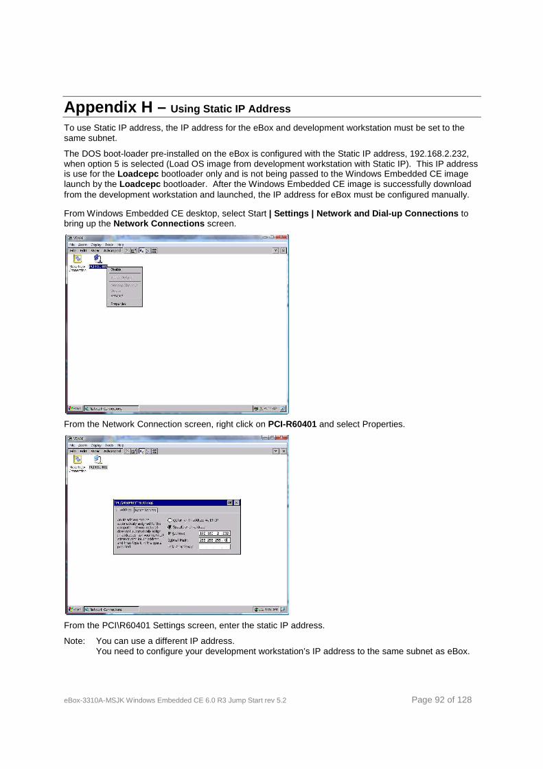
eBox-3310A-MSJK Windows Embedded CE 6.0 R3 Jump Start rev 5.2 Page 92 of 128
Appendix H – Using Static IP Address To use Static IP address, the IP address for the eBox and development workstation must be set to the same subnet.
The DOS boot-loader pre-installed on the eBox is configured with the Static IP address, 192.168.2.232, when option 5 is selected (Load OS image from development workstation with Static IP). This IP address is use for the Loadcepc bootloader only and is not being passed to the Windows Embedded CE image launch by the Loadcepc bootloader. After the Windows Embedded CE image is successfully download from the development workstation and launched, the IP address for eBox must be configured manually.
From Windows Embedded CE desktop, select Start | Settings | Network and Dial-up Connections to bring up the Network Connections screen.
From the Network Connection screen, right click on PCI-R60401 and select Properties.
From the PCI\R60401 Settings screen, enter the static IP address.
Note: You can use a different IP address. You need to configure your development workstation’s IP address to the same subnet as eBox.
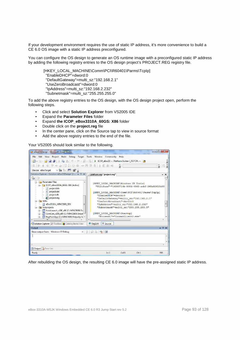
eBox-3310A-MSJK Windows Embedded CE 6.0 R3 Jump Start rev 5.2 Page 93 of 128
If your development environment requires the use of static IP address, it’s more convenience to build a CE 6.0 OS image with a static IP address preconfigured.
You can configure the OS design to generate an OS runtime image with a preconfigured static IP address by adding the following registry entries to the OS design project’s PROJECT.REG registry file.
[HKEY_LOCAL_MACHINE\Comm\PCI\R60401\Parms\TcpIp] "EnableDHCP"=dword:0 "DefaultGateway"=multi_sz:"192.168.2.1" "UseZeroBroadcast"=dword:0 "IpAddress"=multi_sz:"192.168.2.232" "Subnetmask"=multi_sz:"255.255.255.0"
To add the above registry entries to the OS design, with the OS design project open, perform the following steps.
• Click and select Solution Explorer from VS2005 IDE • Expand the Parameter Files folder • Expand the ICOP_eBox3310A_60GS: X86 folder • Double click on the project.reg file • In the center pane, click on the Source tap to view in source format • Add the above registry entries to the end of the file.
Your VS2005 should look similar to the following.
After rebuilding the OS design, the resulting CE 6.0 image will have the pre-assigned static IP address.
eBox-3310A-MSJK Windows Embedded CE 6.0 R3 Jump Start rev 5.2 Page 94 of 128
Appendix I – Recover Jump Start Kit’s Original Files The eBox-3310A-MSJK is preconfigured to boot to Microsoft DOS 6.22 and the necessary files to load the prebuilt CE 6.0 OS runtime images and Ethernet boot loader to download runtime image from the development workstation.
eBox-3310A-MSJK Preconfigured Files The following files are preconfigured in the root of the eBox’s FAT16 file system:
• Loadcepc.exe This is a DOS boot loader for Windows Embedded CE. It can be used to launch a CE 6.0 OS runtime image from the local storage. It can also be used to launch the Ethernet boot loader, Eboot.bin, to establish connectivity with the Platform Builder development workstation and download runtime image from the development workstation to the target device.
• Nk.bin This is the prebuilt CE 6.0 OS runtime image for the jump start kit.
• Vesatest.exe This utility is used to check the system’s supported VESA video display mode.
• Eboot.bin This is the Ethernet boot loader. It’s launched by Loadcepc.exe to establish connectivity with the Platform Builder development workstation and download Windows Embedded CE OS runtime image from the development workstation to the target device.
• Himem.sys This is a DOS device driver to enable DOS to use memory beyond the original 640K limitation, also refer to as extended memory region.
Under DOS 6.22, Loadcepe.exe requires Himem.sys to function.
• Autoexec.bat
This is an auto execution batch file executed by DOS when the system starts. The file is in ASCII text format and can be viewed or edited using any text editor. The Edit.com, a simple text editor, is provided to edit this file.
• Config.sys This is the system startup configuration file. The file is in ASCII text format and can be viewed or edited using any text editor. The Edit.com, a simple text editor, is provided to edit this file
The eBox-3310A-MSJK preconfigured files are provided on the CD-ROM that comes with the jump start kit, in the following directory:
• \MSJK_Files
Recover Damaged Files To recover deleted file or damaged file system, you can perform one of the following:
• Copy the file(s) from the jump start CD-ROM to the eBox’s local storage, overwritten the existing file(s).
• Format the eBox’s IDE flash file system and recover all of the original files from the CD-ROM.
eBox-3310A-MSJK Windows Embedded CE 6.0 R3 Jump Start rev 5.2 Page 95 of 128
Unless the eBox’s storage file system is corrupted and not able to boot, it’s best to copy the needed files from the jump start CD-ROM and avoid formatting the EmbedDisk.
To perform the above recovery tasks, you need to boot eBox from an USB floppy, USB flash storage or USB CD-ROM to recover the file(s).
The eBox-3310A-MSJK can be configured to boot from the following sources:
• IDE storage • USB floppy • USB CD-ROM • USB flash storage • LAN
One of the convenience methods to recover damaged file is to use a bootable USB flash storage, as the transfer medium, to copy file from the jump start CD-ROM to the eBox’s flash storage.
Preparing USB Flash Storage to Boot to DOS Before configuring the eBox to boot from USB flash storage, you need to prepare the USB flash storage to be able to boo to DOS.
Keep in mind there are many different type of USB flash manufactured by different companies with different hardware, and not all of them can be configured to boot to DOS.
It’s important to know that DOS can only address FAT file partition that is 2GB or smaller. So, you need to use an USB flash storage that is 2GB or smaller in size.
For some USB flash storage, making it bootable to DOS can be done with the following simple steps:
• Format the USB flash storage using FAT or FAT16 (not FAT32). • Copy the following DOS system file to the USB flash storage.
o IO.SYS o MSDOS.SYS o COMMAND.COM
There are different version of DOS, such as 6.22, Windows 98 and Windows Millennium. You need to use DOS files from the same version.
You can find these file by searching on the Web using the “DOS boot disk” key word.
Some of the USB flash storage manufacture provide utility to format and configure the USB flash to boot to DOS.
Due to the large pool of available USB flash storages; there is not a procedure or method to make the USB flash bootable to DOS that works for all USB flash in the market.
Some of the USB flash storage devices are built with file encryption, support multiple function and etc. Usually, these multi-function USB flash storage devices cannot be configured to boot to DOS. It’s best to use a simple USB flash storage device that is 2GB or smaller.
In addition to formatting and configuring the USB flash storage to boot to DOS, you also need to copy the necessary DOS utilities to the USB flash storage and use them to format the eBox’s IDE flash storage.
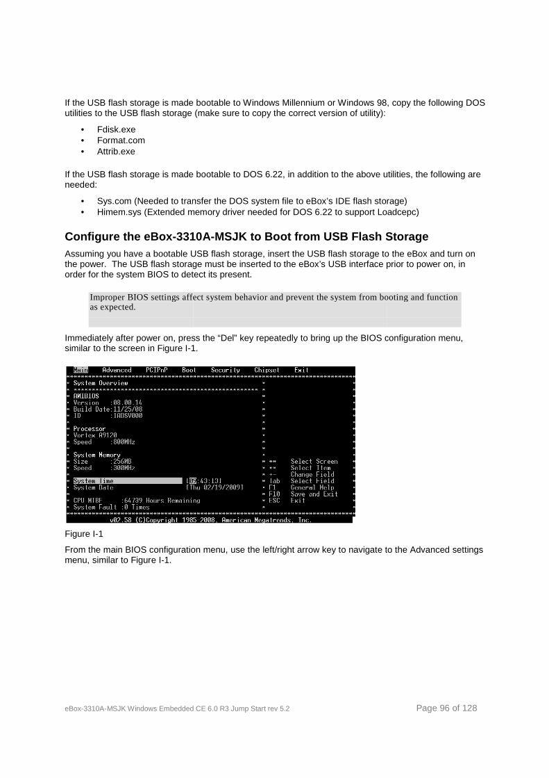
eBox-3310A-MSJK Windows Embedded CE 6.0
If the USB flash storage is made bootable to Windows Millennium or Windows 98, copy the following DOS utilities to the USB flash storage (make sure to copy the correct version of utility):
• Fdisk.exe • Format.com • Attrib.exe
If the USB flash storage is made bootable to DOS 6.22, in addition to the above utilities, the following are needed:
• Sys.com (Needed to transfer the DOS system file to eBox’s IDE flash storage)• Himem.sys (Extended memory driver needed for DOS 6.22 to support Loadcepc)
Configure the eBox-3310AAssuming you have a bootable USB flash storage, insert the USBthe power. The USB flash storage must be inserted to the eBox’s USB interface prior to power on, in order for the system BIOS to detect its present.
Improper BIOS settings affect system behavior and prevent the systeas expected.
Immediately after power on, press the “Del” key repeatedly to bring upsimilar to the screen in Figure I-1.
Figure I-1
From the main BIOS configuration menu, umenu, similar to Figure I-1.
Windows Embedded CE 6.0 R3 Jump Start rev 5.2
If the USB flash storage is made bootable to Windows Millennium or Windows 98, copy the following DOS ities to the USB flash storage (make sure to copy the correct version of utility):
If the USB flash storage is made bootable to DOS 6.22, in addition to the above utilities, the following are
transfer the DOS system file to eBox’s IDE flash storage)Himem.sys (Extended memory driver needed for DOS 6.22 to support Loadcepc)
3310A-MSJK to Boot from USB Flash StorageAssuming you have a bootable USB flash storage, insert the USB flash storage to the eBox and turn on the power. The USB flash storage must be inserted to the eBox’s USB interface prior to power on, in order for the system BIOS to detect its present.
Improper BIOS settings affect system behavior and prevent the system from booting and function
Immediately after power on, press the “Del” key repeatedly to bring up the BIOS configuration menu, 1.
From the main BIOS configuration menu, use the left/right arrow key to navigate to the Advanced settings
Page 96 of 128
If the USB flash storage is made bootable to Windows Millennium or Windows 98, copy the following DOS ities to the USB flash storage (make sure to copy the correct version of utility):
If the USB flash storage is made bootable to DOS 6.22, in addition to the above utilities, the following are
transfer the DOS system file to eBox’s IDE flash storage) Himem.sys (Extended memory driver needed for DOS 6.22 to support Loadcepc)
to Boot from USB Flash Storage flash storage to the eBox and turn on
the power. The USB flash storage must be inserted to the eBox’s USB interface prior to power on, in
m from booting and function
the BIOS configuration menu,
key to navigate to the Advanced settings
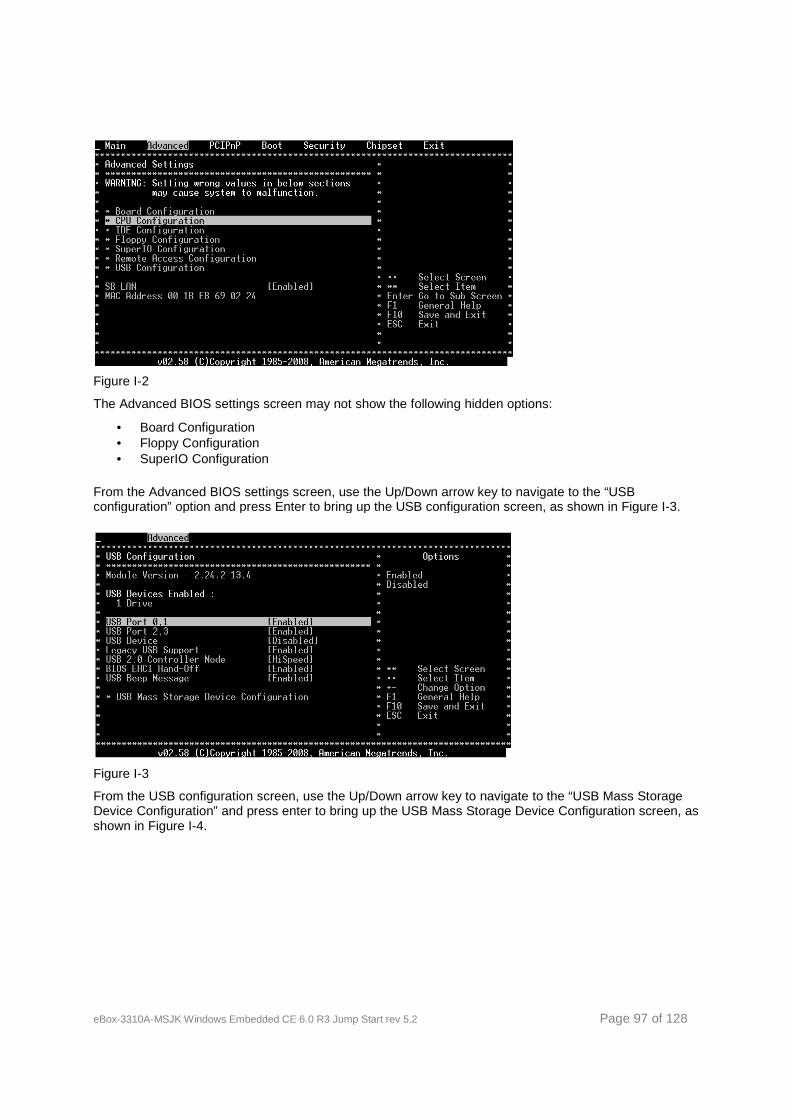
eBox-3310A-MSJK Windows Embedded CE 6.0
Figure I-2
The Advanced BIOS settings screen may not show the following
• Board Configuration • Floppy Configuration • SuperIO Configuration
From the Advanced BIOS settingsconfiguration” option and press Enter to bring up the USB configuration screen, as shown in Figure I
Figure I-3
From the USB configuration screen, uDevice Configuration” and press enter to bring up the USB Mass Storage Device Configuration screen, as shown in Figure I-4.
Windows Embedded CE 6.0 R3 Jump Start rev 5.2
The Advanced BIOS settings screen may not show the following hidden options:
From the Advanced BIOS settings screen, use the Up/Down arrow key to navigate to the “USB configuration” option and press Enter to bring up the USB configuration screen, as shown in Figure I
From the USB configuration screen, use the Up/Down arrow key to navigate to the and press enter to bring up the USB Mass Storage Device Configuration screen, as
Page 97 of 128
se the Up/Down arrow key to navigate to the “USB configuration” option and press Enter to bring up the USB configuration screen, as shown in Figure I-3.
se the Up/Down arrow key to navigate to the “USB Mass Storage and press enter to bring up the USB Mass Storage Device Configuration screen, as
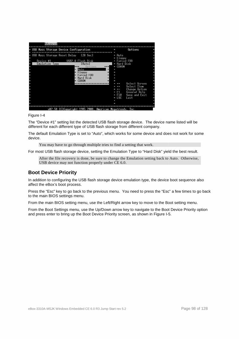
eBox-3310A-MSJK Windows Embedded CE 6.0
Figure I-4
The “Device #1” setting list the detected USB flash storage device. The device name listed will be different for each different type of USB flash storage from different company.
The default Emulation Type is set to “Auto”, which works for some device and does not work for some device.
You may have to go through multiple tries to find a setting that work
For most USB flash storage device, setting the Emulation Type to “Hard Disk” yield the best result.
After the file recovery is done, be sure to change the Emulation setting back to Auto. Otherwise, USB device may not function properly under CE 6.0.
Boot Device Priority In addition to configuring the USB flash storage device emulation type, the device boot sequence also affect the eBox’s boot process.
Press the “Esc” key to go back to the previous menu. You need to press the “Esc” a few times to go backto the main BIOS settings menu.
From the main BIOS setting menu, use the Left/Right arrow key to move to the Boot set
From the Boot Settings menu, use the Up/Down arrow key to navigate to the Boot Device Priority option and press enter to bring up the Boot Device Priority screen, as shown in Figure I
Windows Embedded CE 6.0 R3 Jump Start rev 5.2
The “Device #1” setting list the detected USB flash storage device. The device name listed will be different for each different type of USB flash storage from different company.
The default Emulation Type is set to “Auto”, which works for some device and does not work for some
You may have to go through multiple tries to find a setting that work.
For most USB flash storage device, setting the Emulation Type to “Hard Disk” yield the best result.
After the file recovery is done, be sure to change the Emulation setting back to Auto. Otherwise, USB device may not function properly under CE 6.0.
In addition to configuring the USB flash storage device emulation type, the device boot sequence also
Press the “Esc” key to go back to the previous menu. You need to press the “Esc” a few times to go backto the main BIOS settings menu.
From the main BIOS setting menu, use the Left/Right arrow key to move to the Boot set
From the Boot Settings menu, use the Up/Down arrow key to navigate to the Boot Device Priority option up the Boot Device Priority screen, as shown in Figure I-5.
Page 98 of 128
The “Device #1” setting list the detected USB flash storage device. The device name listed will be
The default Emulation Type is set to “Auto”, which works for some device and does not work for some
For most USB flash storage device, setting the Emulation Type to “Hard Disk” yield the best result.
After the file recovery is done, be sure to change the Emulation setting back to Auto. Otherwise,
In addition to configuring the USB flash storage device emulation type, the device boot sequence also
Press the “Esc” key to go back to the previous menu. You need to press the “Esc” a few times to go back
From the main BIOS setting menu, use the Left/Right arrow key to move to the Boot setting menu.
From the Boot Settings menu, use the Up/Down arrow key to navigate to the Boot Device Priority option 5.
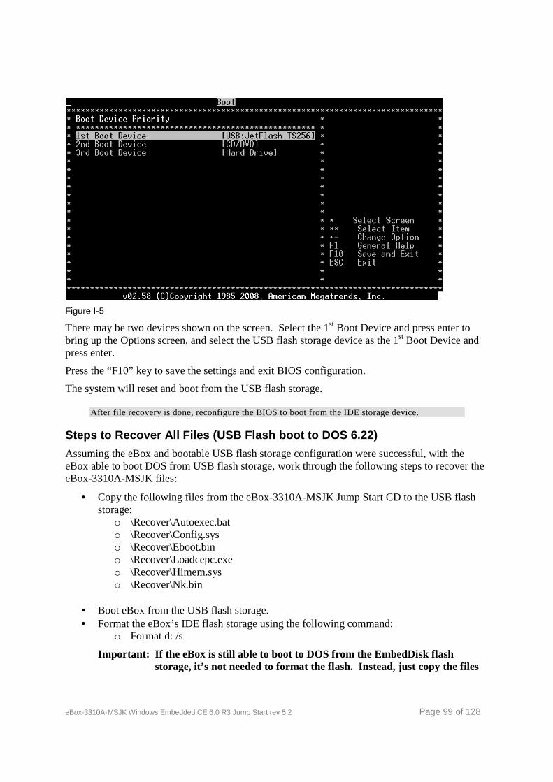
eBox-3310A-MSJK Windows Embedded CE 6.0
Figure I-5
There may be two devices shown on the screen. Select the 1bring up the Options screen, and select the USB flash storage device as the 1press enter.
Press the “F10” key to save the settings and exit BIOS configuration.
The system will reset and boot from the USB flash storage.
After file recovery is done, reconfigure the BIOS to boot from the
Steps to Recover All Files (USB Flash boot to DOS 6.22)
Assuming the eBox and bootable USB flash storage configuration were successful, with the eBox able to boot DOS from USB flash storage, work through the following steps to recover the eBox-3310A-MSJK files:
• Copy the following files from the storage:
o \Recover\Autoexec.bato \Recover\Config.syso \Recover\Eboot.bino \Recover\Loadcepc.exeo \Recover\Himem.syso \Recover\Nk.bin
• Boot eBox from the USB flash storage.• Format the eBox’s IDE flash storage using the following command:
o Format d: /s
Important: If the eBox is still able to boot to DOS from the storage, it’s not needed to format the flash. Instead, just copy the files
Windows Embedded CE 6.0 R3 Jump Start rev 5.2
There may be two devices shown on the screen. Select the 1st Boot Device and press enter to bring up the Options screen, and select the USB flash storage device as the 1
Press the “F10” key to save the settings and exit BIOS configuration.
The system will reset and boot from the USB flash storage.
After file recovery is done, reconfigure the BIOS to boot from the IDE storage device.
Recover All Files (USB Flash boot to DOS 6.22)
Assuming the eBox and bootable USB flash storage configuration were successful, with the from USB flash storage, work through the following steps to recover the
y the following files from the eBox-3310A-MSJK Jump Start CD to the USB flash
Autoexec.bat Config.sys Eboot.bin Loadcepc.exe Himem.sys Nk.bin
the USB flash storage. Box’s IDE flash storage using the following command:
If the eBox is still able to boot to DOS from the EmbedDiskstorage, it’s not needed to format the flash. Instead, just copy the files
Page 99 of 128
Boot Device and press enter to bring up the Options screen, and select the USB flash storage device as the 1st Boot Device and
IDE storage device.
Assuming the eBox and bootable USB flash storage configuration were successful, with the from USB flash storage, work through the following steps to recover the
CD to the USB flash
Box’s IDE flash storage using the following command:
EmbedDisk flash storage, it’s not needed to format the flash. Instead, just copy the files

eBox-3310A-MSJK Windows Embedded CE 6.0 R3 Jump Start rev 5.2 Page 100 of 128
from the jump start CD-ROM to the eBox’s EmbedDisk and overwritten the corrupted file.
The USB flash storage is emulated as hard drive and become drive C: after booting to DOS, with drive D: assigned to the eBox’s EmbedDisk flash storage.
If the USB flash storage is emulated as the floppy drive and become drive A: after booting to DOS, the drive letter C: will be assigned to the eBox’s EmbedDisk flash storage. In this case, use the following format command:
Format C: /s
The “/s” parameter instruct the Format utility to transfer DOS system to the EmbedDisk flash storage after formatting.
• Copy the following files from the USB flash storage to the eBox’s flash storage: o Autoexec.bat o Config.sys o Eboot.bin o Himem.sys o Loadcepc.exe o Nk.bin
Remove the USB flash storage and reboot eBox. Immediately after eBox power reset, press the “Del” key to enter BIOS configuration and navigate to the Boot Settings menu to configure the Boot Device Priority to configure the eBox’s IDE device as the 1st boot device.
Note: If the EmbedDisk is recovered with a different version of DOS, the Config.sys, the DOS startup configuration file, may need to be modified to meet the particular version of DOS being use.
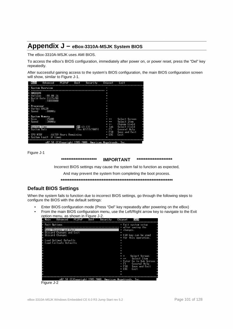
eBox-3310A-MSJK Windows Embedded CE 6.0
Appendix J – eBox
The eBox-3310A-MSJK uses AMI BIOS.
To access the eBox’s BIOS configuration, immediately after power on, or power reset, press the “Del” key repeatedly.
After successful gaining access to the system’s BIOS configuration, the main BIOS configuration screewill show, similar to Figure J-1.
Figure J-1
******************** IMPORTANT ******
Incorrect BIOS settings may cause the system fail to function as expected,
And may prevent the system from completing the boot process.
************************
Default BIOS Settings When the system fails to function due to incorrect BIOS settings, go through the following steps to configure the BIOS with the default settings:
• Enter BIOS configuration mode (Press “Del” key repeatedly after powering• From the main BIOS configuration menu, use the Left/Right arrow key to navigate to the Exit
option menu, as shown in Figure J
Figure J-2
Windows Embedded CE 6.0 R3 Jump Start rev 5.2
eBox -3310A-MSJK System BIOS
uses AMI BIOS.
access the eBox’s BIOS configuration, immediately after power on, or power reset, press the “Del” key
After successful gaining access to the system’s BIOS configuration, the main BIOS configuration scree
********** IMPORTANT ****************
Incorrect BIOS settings may cause the system fail to function as expected,
And may prevent the system from completing the boot process.
***************************************************************
When the system fails to function due to incorrect BIOS settings, go through the following steps to configure the BIOS with the default settings:
Enter BIOS configuration mode (Press “Del” key repeatedly after poweringFrom the main BIOS configuration menu, use the Left/Right arrow key to navigate to the Exit
ption menu, as shown in Figure J-2.
Page 101 of 128
access the eBox’s BIOS configuration, immediately after power on, or power reset, press the “Del” key
After successful gaining access to the system’s BIOS configuration, the main BIOS configuration screen
**************
Incorrect BIOS settings may cause the system fail to function as expected,
And may prevent the system from completing the boot process.
***************
When the system fails to function due to incorrect BIOS settings, go through the following steps to
Enter BIOS configuration mode (Press “Del” key repeatedly after powering on the eBox) From the main BIOS configuration menu, use the Left/Right arrow key to navigate to the Exit

eBox-3310A-MSJK Windows Embedded CE 6.0 R3 Jump Start rev 5.2 Page 102 of 128
• From the Exit Options menu, use the Up/Down arrow key to navigate to the “Load FailSafe Defaults” and press the “Enter” key.
• When the “Load Failsafe Defaults?” screen comes up, select OK. • From the Exit Options menu, use the Up/Down arrow key to navigate to the “Load Optimal
Defaults” and press the “Enter” key. • Press the “Esc” key to go back to the main BIOS setting menu. • From the main BIOS setting menu, use the Left/Right arrow key to navigate to the Advanced
Settings menu. • Use the Up/Down arrow key to navigate to the IDE Configuration option and press enter to bring
up the IDE Configuration menu. • From the IDE Configuration menu, use the Up/Down arrow key to navigate to the “OnBoard IDE
Operate Mode” and press “Enter” to bring up the Options dialog box. • Select “Native Mode and press “Enter” • Press the “Esc” key to go back to the main BIOS setting menu. • Use the Right/Left arrow key to navigate to the Advanced PCI/PnP settings screen. • Use the Up/Down arrow key to navigate to the PCI IDE BusMaster option and press “Enter”. • From the Options dialog box, select “Enabled” and press “Enter”.
BIOS Settings Impacting IDE Storage in CE 6.0 The ICOP_eBox3310A_60GS BSP is configured to support the eBox-3310A-MSJK preconfigured with the following IDE and PCI-PnP BIOS settings:
• The “OnBoard IDE Operate Mode” setting, one of the Advanced BIOS settings, is configured to “Native Mode”.
• The “PCI IDE BusMaster” setting, one of the Advanced PCI/PnP settings, is configured to “Enabled”.
In addition to the above, check to make sure the 1st Boot Device, from the Boot Device Priority settings, is configured to boot from the correct device.

eBox-3310A-MSJK Windows Embedded CE 6.0 R3 Jump Start rev 5.2 Page 103 of 128
Appendix K – Configure System BIOS to Boot from USB Flash Storag e
The eBox-3310A-MSJK uses AMI BIOS.
To access the eBox’s BIOS configuration, immediately after power on, or power reset, press the “Del” key repeatedly.
******************** IMPORTANT ********************
Incorrect BIOS settings may cause the system fail to function as expected,
And may prevent the system from completing the boot process.
***************************************************************
Preparing USB Flash Storage to Boot to DOS Before configuring the eBox to boot from USB flash storage, you need to prepare the USB flash storage to be able to boo to DOS.
Keep in mind there are many different type of USB flash manufactured by different companies with different hardware, and not all USB flash storage device can be configured to boot to DOS.
It’s important to know that DOS can only address FAT file partition that is 2GB or smaller. So, you need to use an USB flash storage that is 2GB or smaller in size.
For some USB flash storage, making it bootable to DOS can be done with the following simple steps:
• Format the USB flash storage using FAT or FAT16 (not FAT32). • Copy the following DOS system file to the USB flash storage.
o IO.SYS o MSDOS.SYS o COMMAND.COM
There are different version of DOS, such as 6.22, Windows 98 and Windows Millennium. You need to use DOS files from the same version.
You can find these file by searching on the Web using the “DOS boot disk” key word.
Some of the USB flash storage manufacture provide utility to format and configure the USB flash to boot to DOS.
Due to the large pool of available USB flash storages; there is not a procedure or method to make the USB flash bootable to DOS that works for all USB flash in the market.
Some of the USB flash storage devices are built with file encryption, support multiple function and etc. Usually, these multi-function USB flash storage devices cannot be configured to boot to DOS. It’s best to use a simple USB flash storage device that is 2GB or smaller.
In addition to formatting and configuring the USB flash storage to boot to DOS, you also need to copy the necessary DOS utilities to the USB flash storage and use them to format the eBox’s IDE flash storage.
If the USB flash storage is made bootable to Windows Millennium or Windows 98, copy the following DOS utilities to the USB flash storage (make sure to copy the correct version of utility):
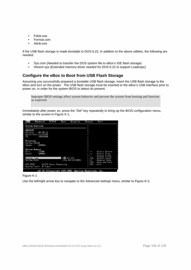
eBox-3310A-MSJK Windows Embedded CE 6.0
• Fdisk.exe • Format.com • Attrib.exe
If the USB flash storage is made bootable to DOS 6.22, in addition to the above utilities, the following are needed:
• Sys.com (Needed to transfer the DOS system file to eBox’s IDE flash storage)• Himem.sys (Extended memory driver
Configure the eBox to Boot from USB Flash StorageAssuming you successfully preparedeBox and turn on the power. The USB flash storage must be inserpower on, in order for the system BIOS to detect its present.
Improper BIOS settings affect system behavior and prevent the system from booting and function as expected.
Immediately after power on, press the “Del”similar to the screen in Figure K-
Figure K-1
Use the left/right arrow key to navigate to the Advanced se
Windows Embedded CE 6.0 R3 Jump Start rev 5.2
If the USB flash storage is made bootable to DOS 6.22, in addition to the above utilities, the following are
Sys.com (Needed to transfer the DOS system file to eBox’s IDE flash storage)Himem.sys (Extended memory driver needed for DOS 6.22 to support Loadcepc)
to Boot from USB Flash Storage Assuming you successfully prepared a bootable USB flash storage, insert the USB flash storage to the eBox and turn on the power. The USB flash storage must be inserted to the eBox’s USB interface prior to power on, in order for the system BIOS to detect its present.
Improper BIOS settings affect system behavior and prevent the system from booting and function
Immediately after power on, press the “Del” key repeatedly to bring up the BIOS configuration menu, -1.
Use the left/right arrow key to navigate to the Advanced settings menu, similar to Figure K
Page 104 of 128
If the USB flash storage is made bootable to DOS 6.22, in addition to the above utilities, the following are
Sys.com (Needed to transfer the DOS system file to eBox’s IDE flash storage) needed for DOS 6.22 to support Loadcepc)
a bootable USB flash storage, insert the USB flash storage to the ted to the eBox’s USB interface prior to
Improper BIOS settings affect system behavior and prevent the system from booting and function
key repeatedly to bring up the BIOS configuration menu,
ttings menu, similar to Figure K-2.
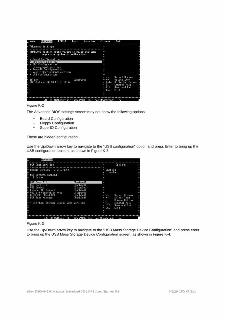
eBox-3310A-MSJK Windows Embedded CE 6.0
Figure K-2
The Advanced BIOS settings screen may not
• Board Configuration • Floppy Configuration • SuperIO Configuration
These are hidden configuration.
Use the Up/Down arrow key to navigate to the “USB configuration” option and press Enter to bring up the USB configuration screen, as shown in Figure K
Figure K-3
Use the Up/Down arrow key to navigate to the “USB Mass Storage Device Configuration” and press enter to bring up the USB Mass Storage Device Configurat
Windows Embedded CE 6.0 R3 Jump Start rev 5.2
The Advanced BIOS settings screen may not show the following options:
Use the Up/Down arrow key to navigate to the “USB configuration” option and press Enter to bring up the s shown in Figure K-3.
Use the Up/Down arrow key to navigate to the “USB Mass Storage Device Configuration” and press enter to bring up the USB Mass Storage Device Configuration screen, as shown in Figure K
Page 105 of 128
Use the Up/Down arrow key to navigate to the “USB configuration” option and press Enter to bring up the
Use the Up/Down arrow key to navigate to the “USB Mass Storage Device Configuration” and press enter ion screen, as shown in Figure K-4.
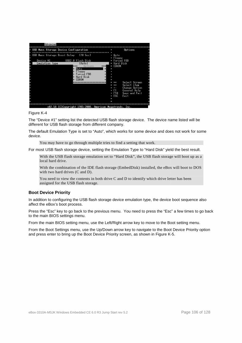
eBox-3310A-MSJK Windows Embedded CE 6.0
Figure K-4
The “Device #1” setting list the detected USB flash storage device. The device name listed will be different for USB flash storage from different company.
The default Emulation Type is set to “Auto”, which works for some device and does not work for some device.
You may have to go through multiple tries to find a setting that work.
For most USB flash storage device, setting the Emulation Type to “Hard Disk” yield the best result.
With the USB flash storage emulation set to “Hard Disk”, the USB flash storage will boot up alocal hard drive.
With the combination of the IDE flash storage (EmbedDisk) installed, the eBox will boot to DOS with two hard drives (C and D).
You need to view the contents in both drive C and D to identify which drive letter has been assigned for the USB flash storage.
Boot Device Priority
In addition to configuring the USB flash storage device emulation type, the device boot sequence also affect the eBox’s boot process.
Press the “Esc” key to go back to the previous menu. You need to press the “to the main BIOS settings menu.
From the main BIOS setting menu, use the Left/Right arrow key to move to the Boot setting menu.
From the Boot Settings menu, use the Up/Down arrow key to navigate to the Boot Device Priority optioand press enter to bring up the Boot Device Prior
Windows Embedded CE 6.0 R3 Jump Start rev 5.2
setting list the detected USB flash storage device. The device name listed will be different for USB flash storage from different company.
The default Emulation Type is set to “Auto”, which works for some device and does not work for some
have to go through multiple tries to find a setting that work.
For most USB flash storage device, setting the Emulation Type to “Hard Disk” yield the best result.
With the USB flash storage emulation set to “Hard Disk”, the USB flash storage will boot up a
With the combination of the IDE flash storage (EmbedDisk) installed, the eBox will boot to DOS with two hard drives (C and D).
You need to view the contents in both drive C and D to identify which drive letter has been the USB flash storage.
In addition to configuring the USB flash storage device emulation type, the device boot sequence also
Press the “Esc” key to go back to the previous menu. You need to press the “Esc” a few times to go back to the main BIOS settings menu.
From the main BIOS setting menu, use the Left/Right arrow key to move to the Boot setting menu.
From the Boot Settings menu, use the Up/Down arrow key to navigate to the Boot Device Priority optioand press enter to bring up the Boot Device Priority screen, as shown in Figure K
Page 106 of 128
setting list the detected USB flash storage device. The device name listed will be
The default Emulation Type is set to “Auto”, which works for some device and does not work for some
For most USB flash storage device, setting the Emulation Type to “Hard Disk” yield the best result.
With the USB flash storage emulation set to “Hard Disk”, the USB flash storage will boot up as a
With the combination of the IDE flash storage (EmbedDisk) installed, the eBox will boot to DOS
You need to view the contents in both drive C and D to identify which drive letter has been
In addition to configuring the USB flash storage device emulation type, the device boot sequence also
Esc” a few times to go back
From the main BIOS setting menu, use the Left/Right arrow key to move to the Boot setting menu.
From the Boot Settings menu, use the Up/Down arrow key to navigate to the Boot Device Priority option ity screen, as shown in Figure K-5.
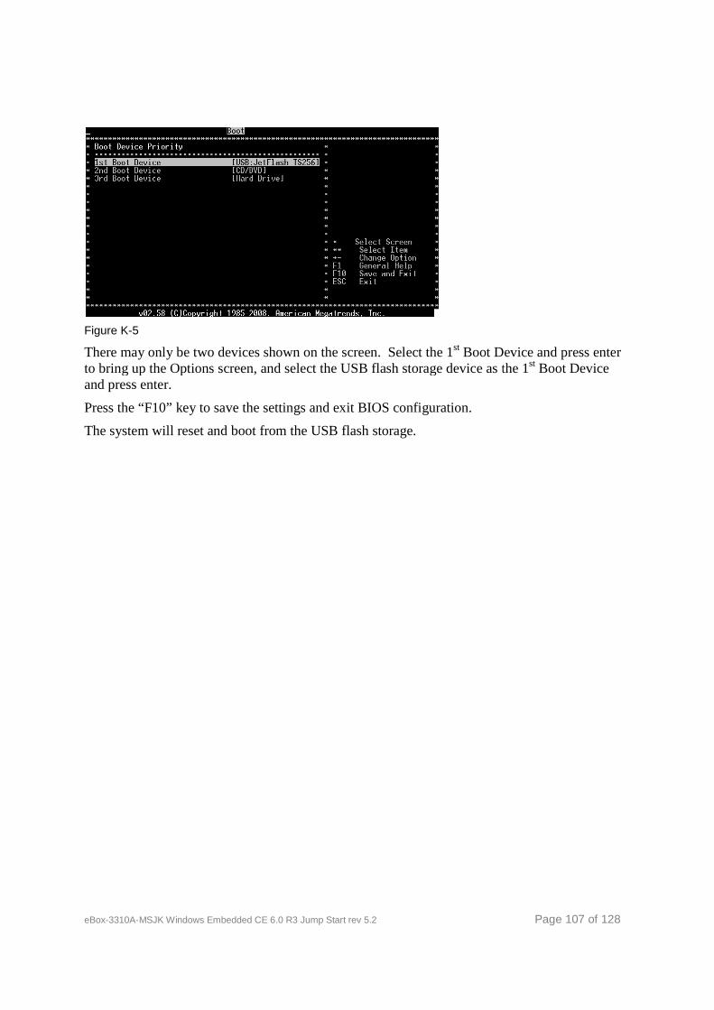
eBox-3310A-MSJK Windows Embedded CE 6.0
Figure K-5
There may only be two devices shown on the screen. Select the 1to bring up the Options screen, and select the USB flash storage device as the 1and press enter.
Press the “F10” key to save the settings and exit BIOS configuration.
The system will reset and boot from the USB f
Windows Embedded CE 6.0 R3 Jump Start rev 5.2
be two devices shown on the screen. Select the 1st Boot Device and press enter to bring up the Options screen, and select the USB flash storage device as the 1
Press the “F10” key to save the settings and exit BIOS configuration.
The system will reset and boot from the USB flash storage.
Page 107 of 128
Boot Device and press enter to bring up the Options screen, and select the USB flash storage device as the 1st Boot Device
eBox-3310A-MSJK Windows Embedded CE 6.0 R3 Jump Start rev 5.2 Page 108 of 128
Appendix L – eBox-3310A-MSJK Jump Start CD-ROM
The BSP, SDK and prebuilt OS runtime image for the eBox-3310A-MSJK, along with sample codes and utility are provided in the following directories on the CD-ROM:
• \eBoot\ The Ethernet boot loader, eboot.bin, is in this folder.
• \MSJK_Files\ This folder contains all of the files from the eBox’s IDE flash storage.
In the event the files on the eBox’s IDE storage are corrupted, use these files to recover.
• \SampleCodes\Application\ Six sample application projects are provided in this folder..
o VB2005_SerialPortApplication.zip This is a simple serial port application written in Visual Basic 2005.
o VB2008_SerialPortApplication.zip This is a simple serial port application written in Visual Basic 2008.
o VS2005_HelloWorld.zip This is the managed code hello world sample written in Visual C# 2005.
o VS2005_Win32.zip This is the native code hello world sample written in Visual C++ 2005.
o VS2008_HelloWorld.zip This is the managed code hello world sample written in Visual C# 2008.
o VS2008_Win32.zip This is the native code hello world sample written in Visual C++ 2008.
• \SampleCodes\OSDesign\ The sample project for the OS design exercise, eBoxOSDesign, is included in the zip file in this folder.
o eBoxOSDesign_Project.zip
To use this project, unzip the complete project folder to the following directory: C:\WINCE600\OSDesigns\
• \Software BSP and SDK for the eBox-3310A-MSJK along with the other utility are located in this folder.
o ICOP_eBox3310A_60G_BSP.msi This is the CE 6.0 Board-Support-Package.
o eBox3310A_WINCE600_SDK.msi This is the CE 6.0 SDK.
o AutoLaunch_v200_x86_WinCE600.msi The AutoLaunch component is installed as one of the catalog component to the Platform Builder.
o CoreCon_v200_x86_WinCE600.msi The CoreCon component is installed as one of the catalog component to the Platform Builder.
o RegFlushApp_v100_x86_WinCE600.msi The RegFlushApp component is installed as one of the catalog component to the Platform Builder.
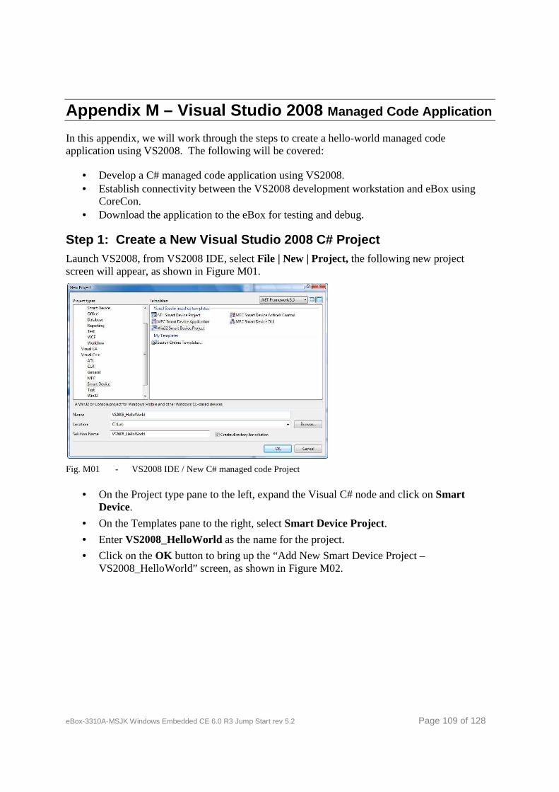
eBox-3310A-MSJK Windows Embedded CE 6.0 R3 Jump Start rev 5.2 Page 109 of 128
Appendix M – Visual Studio 2008 Managed Code Application
In this appendix, we will work through the steps to create a hello-world managed code application using VS2008. The following will be covered:
• Develop a C# managed code application using VS2008. • Establish connectivity between the VS2008 development workstation and eBox using
CoreCon. • Download the application to the eBox for testing and debug.
Step 1: Create a New Visual Studio 2008 C# Project Launch VS2008, from VS2008 IDE, select File | New | Project, the following new project screen will appear, as shown in Figure M01.
Fig. M01 - VS2008 IDE / New C# managed code Project
• On the Project type pane to the left, expand the Visual C# node and click on Smart Device.
• On the Templates pane to the right, select Smart Device Project.
• Enter VS2008_HelloWorld as the name for the project.
• Click on the OK button to bring up the “Add New Smart Device Project – VS2008_HelloWorld” screen, as shown in Figure M02.
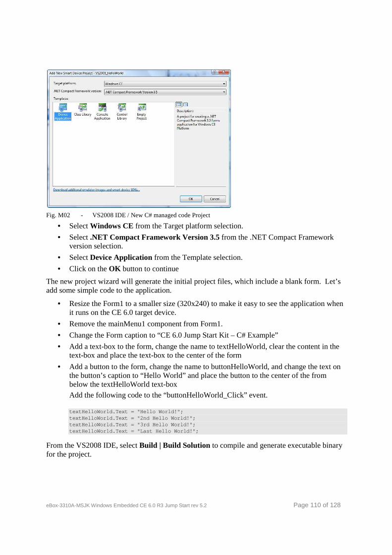
eBox-3310A-MSJK Windows Embedded CE 6.0 R3 Jump Start rev 5.2 Page 110 of 128
Fig. M02 - VS2008 IDE / New C# managed code Project
• Select Windows CE from the Target platform selection.
• Select .NET Compact Framework Version 3.5 from the .NET Compact Framework version selection.
• Select Device Application from the Template selection.
• Click on the OK button to continue
The new project wizard will generate the initial project files, which include a blank form. Let’s add some simple code to the application.
• Resize the Form1 to a smaller size (320x240) to make it easy to see the application when it runs on the CE 6.0 target device.
• Remove the mainMenu1 component from Form1.
• Change the Form caption to “CE 6.0 Jump Start Kit – C# Example”
• Add a text-box to the form, change the name to textHelloWorld, clear the content in the text-box and place the text-box to the center of the form
• Add a button to the form, change the name to buttonHelloWorld, and change the text on the button’s caption to “Hello World” and place the button to the center of the from below the textHelloWorld text-box
Add the following code to the “buttonHelloWorld_Click” event.
textHelloWorld.Text = "Hello World!"; textHelloWorld.Text = "2nd Hello World!"; textHelloWorld.Text = "3rd Hello World!"; textHelloWorld.Text = "Last Hello World!";
From the VS2008 IDE, select Build | Build Solution to compile and generate executable binary for the project.
eBox-3310A-MSJK Windows Embedded CE 6.0 R3 Jump Start rev 5.2 Page 111 of 128
Step 2: Preparing eBox to Connect to Visual Studio 2008 To perform this portion of the exercise, CE 6.0 image configured and built during the previous sections of this guide must be downloaded and running on the eBox, and the eBox3310A_WINCE600_SDK must be installed.
We will use CoreCon to establish the connectivity between the VS2008 development workstation and eBox.
The following 5 CoreCon files need to be copied to \Windows folder on eBox, with CE 6.0 running.
• Clientshutdown.exe
• ConmanClient2.exe
• CMaccept.exe
• eDbgTL.dll
• TcpConnectionA.dll
These files are installed to the following directory on the VS2008 development workstation, as part of the VS2008 installation.
\Program Files\Common Files\Microsoft Shared\CoreCo n\1.0\Target\wce400\
CoreCon components supporting different CPU architectures are provided. There are multiple sub folders under the above directory, with names corresponding to the each CPU family, containing the CoreCon files for each CPU family. CoreCon files supporting the eBox, built with x86 CPU, are in the \x86 sub folder.
In the earlier section, during the customizing OS design steps, the CoreCon_v200_x86 component is added to the OS design. By adding this component, the CoreCon files are included in the OS design and compiled as part of the CE 6.0 OS runtime image generated from the OS design.
To establish connectivity between the VS2008 development workstation and eBox, we need to know the eBox’s IP address. Work through the following steps to find the IP address for eBox:
• From eBox desktop, with CE 6.0 running, click on Start | Run from CE 6.0 desktop with the CMD command to open a console command window, as shown in Figure M03.
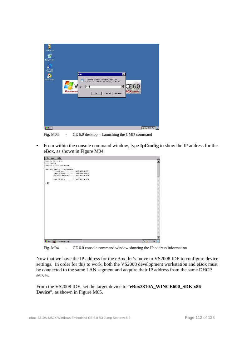
eBox-3310A-MSJK Windows Embedded CE 6.0 R3 Jump Start rev 5.2 Page 112 of 128
Fig. M03 - CE 6.0 desktop – Launching the CMD command
• From within the console command window, type IpConfig to show the IP address for the eBox, as shown in Figure M04.
Fig. M04 - CE 6.0 console command window showing the IP address information
Now that we have the IP address for the eBox, let’s move to VS2008 IDE to configure device settings. In order for this to work, both the VS2008 development workstation and eBox must be connected to the same LAN segment and acquire their IP address from the same DHCP server.
From the VS2008 IDE, set the target device to “eBox3310A_WINCE600_SDK x86 Device”, as shown in Figure M05.
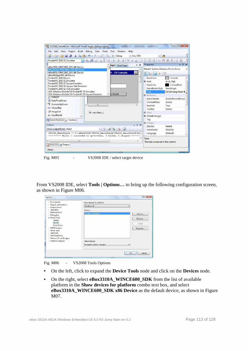
eBox-3310A-MSJK Windows Embedded CE 6.0 R3 Jump Start rev 5.2 Page 113 of 128
Fig. M05 - VS2008 IDE / select target device
From VS2008 IDE, select Tools | Options… to bring up the following configuration screen, as shown in Figure M06.
Fig. M06 - VS2008 Tools Options
• On the left, click to expand the Device Tools node and click on the Devices node.
• On the right, select eBox3310A_WINCE600_SDK from the list of available platform in the Show devices for platform combo text box, and select eBox3310A_WINCE600_SDK x86 Device as the default device, as shown in Figure M07.
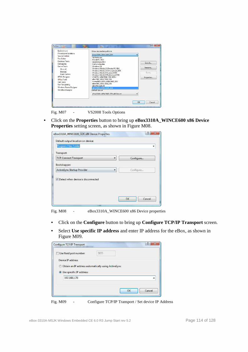
eBox-3310A-MSJK Windows Embedded CE 6.0 R3 Jump Start rev 5.2 Page 114 of 128
Fig. M07 - VS2008 Tools Options
• Click on the Properties button to bring up eBox3310A_WINCE600 x86 Device Properties setting screen, as shown in Figure M08.
Fig. M08 - eBox3310A_WINCE600 x86 Device properties
• Click on the Configure button to bring up Configure TCP/IP Transport screen.
• Select Use specific IP address and enter IP address for the eBox, as shown in Figure M09.
Fig. M09 - Configure TCP/IP Transport / Set device IP Address
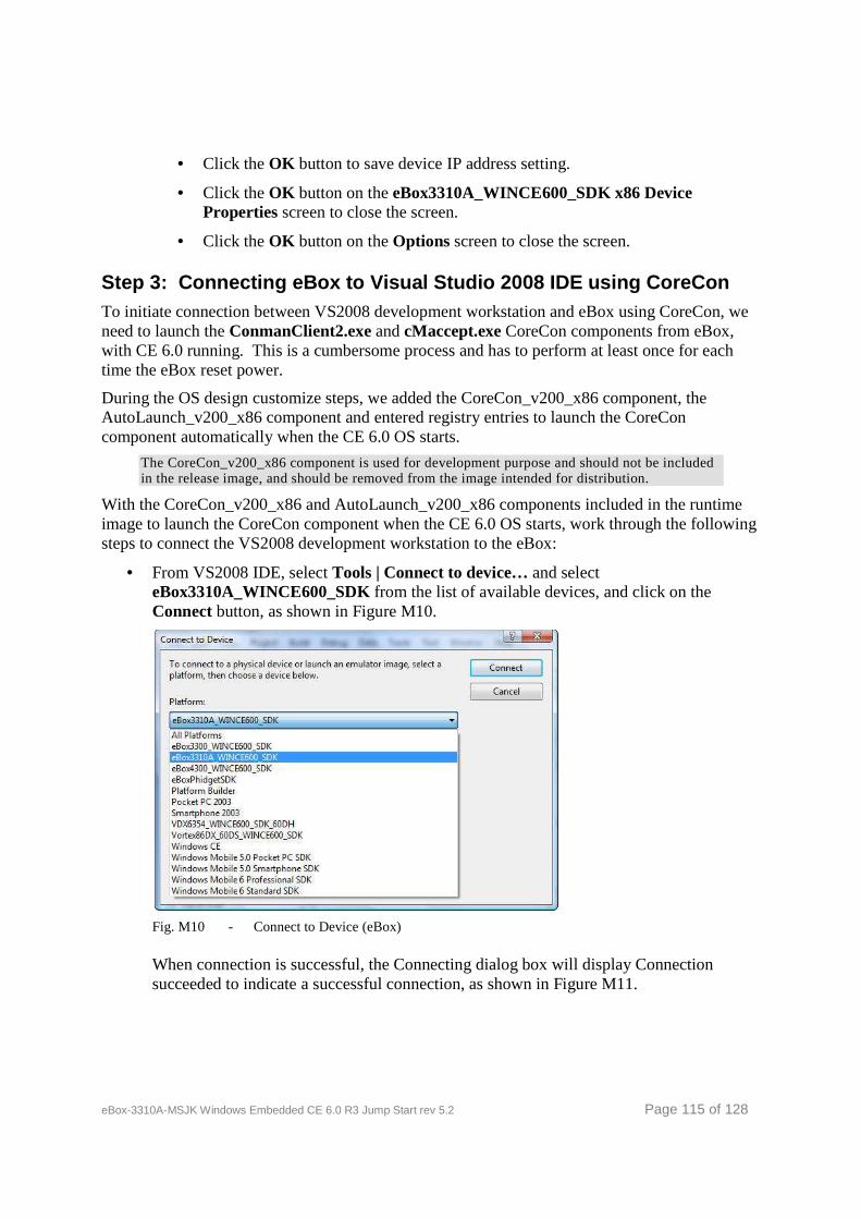
eBox-3310A-MSJK Windows Embedded CE 6.0 R3 Jump Start rev 5.2 Page 115 of 128
• Click the OK button to save device IP address setting.
• Click the OK button on the eBox3310A_WINCE600_SDK x86 Device Properties screen to close the screen.
• Click the OK button on the Options screen to close the screen.
Step 3: Connecting eBox to Visual Studio 2008 IDE using CoreCon To initiate connection between VS2008 development workstation and eBox using CoreCon, we need to launch the ConmanClient2.exe and cMaccept.exe CoreCon components from eBox, with CE 6.0 running. This is a cumbersome process and has to perform at least once for each time the eBox reset power.
During the OS design customize steps, we added the CoreCon_v200_x86 component, the AutoLaunch_v200_x86 component and entered registry entries to launch the CoreCon component automatically when the CE 6.0 OS starts.
The CoreCon_v200_x86 component is used for development purpose and should not be included in the release image, and should be removed from the image intended for distribution.
With the CoreCon_v200_x86 and AutoLaunch_v200_x86 components included in the runtime image to launch the CoreCon component when the CE 6.0 OS starts, work through the following steps to connect the VS2008 development workstation to the eBox:
• From VS2008 IDE, select Tools | Connect to device… and select eBox3310A_WINCE600_SDK from the list of available devices, and click on the Connect button, as shown in Figure M10.
Fig. M10 - Connect to Device (eBox)
When connection is successful, the Connecting dialog box will display Connection succeeded to indicate a successful connection, as shown in Figure M11.
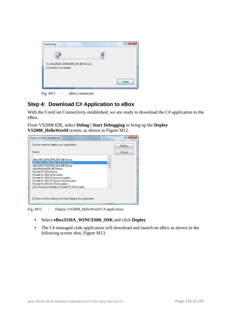
eBox-3310A-MSJK Windows Embedded CE 6.0 R3 Jump Start rev 5.2 Page 116 of 128
Fig. M11 - eBox connected
Step 4: Download C# Application to eBox With the CoreCon Connectivity established, we are ready to download the C# application to the eBox.
From VS2008 IDE, select Debug | Start Debugging to bring up the Deploy VS2008_HelloWorld screen, as shown in Figure M12.
Fig. M12 - Deploy VS2008_HelloWorld C# application
• Select eBox3310A_WINCE600_SDK and click Deploy
• The C# managed code application will download and launch on eBox as shown in the following screen shot, Figure M13.
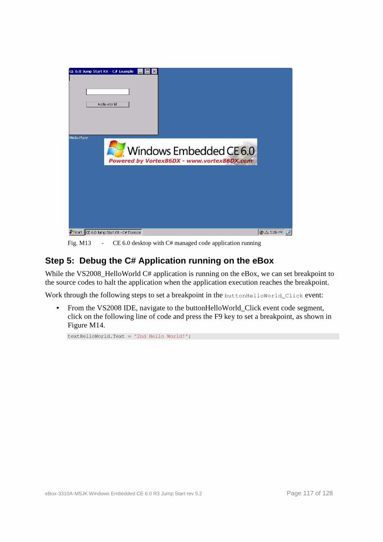
eBox-3310A-MSJK Windows Embedded CE 6.0 R3 Jump Start rev 5.2 Page 117 of 128
Fig. M13 - CE 6.0 desktop with C# managed code application running
Step 5: Debug the C# Application running on the eB ox While the VS2008_HelloWorld C# application is running on the eBox, we can set breakpoint to the source codes to halt the application when the application execution reaches the breakpoint.
Work through the following steps to set a breakpoint in the buttonHelloWorld_Click event:
• From the VS2008 IDE, navigate to the buttonHelloWorld_Click event code segment, click on the following line of code and press the F9 key to set a breakpoint, as shown in Figure M14. textHelloWorld.Text = "2nd Hello World!" ;
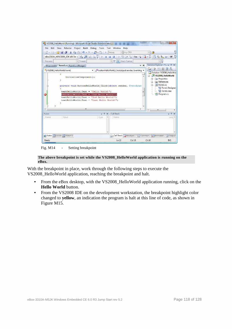
eBox-3310A-MSJK Windows Embedded CE 6.0 R3 Jump Start rev 5.2 Page 118 of 128
Fig. M14 - Setting breakpoint
The above breakpoint is set while the VS2008_HelloWorld application is running on the eBox.
With the breakpoint in place, work through the following steps to execute the VS2008_HelloWorld application, reaching the breakpoint and halt.
• From the eBox desktop, with the VS2008_HelloWorld application running, click on the Hello World button.
• From the VS2008 IDE on the development workstation, the breakpoint highlight color changed to yellow, an indication the program is halt at this line of code, as shown in Figure M15.
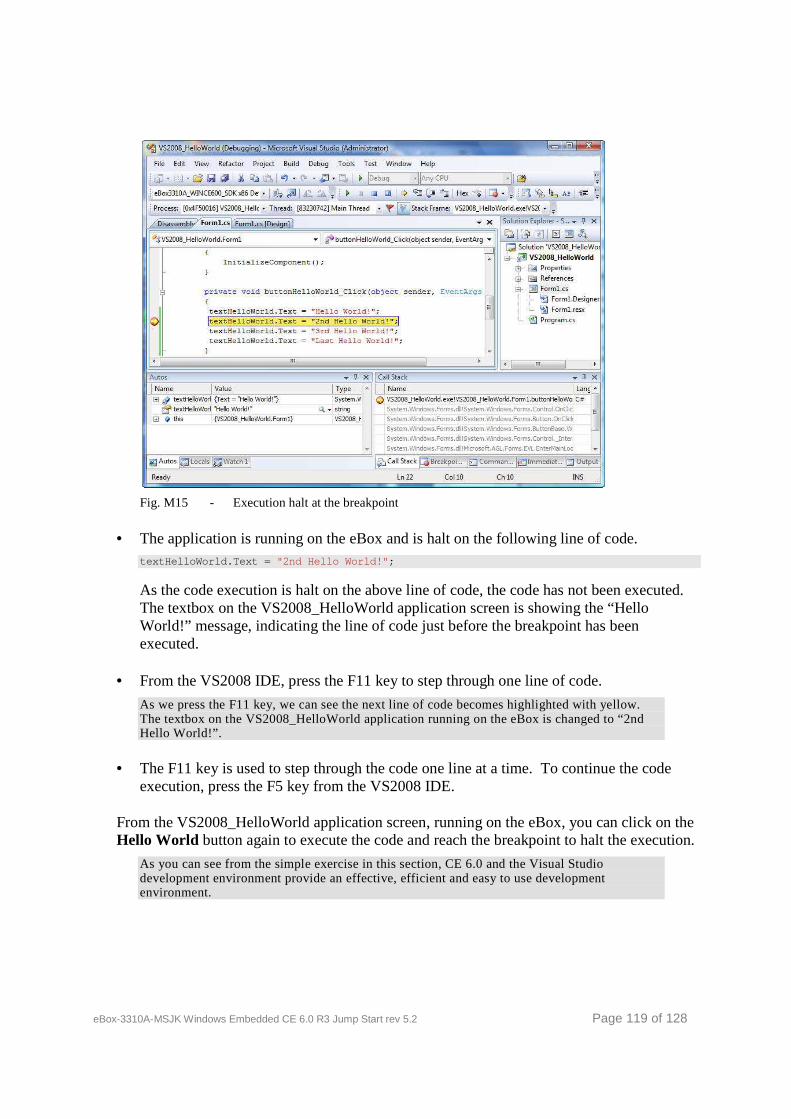
eBox-3310A-MSJK Windows Embedded CE 6.0 R3 Jump Start rev 5.2 Page 119 of 128
Fig. M15 - Execution halt at the breakpoint
• The application is running on the eBox and is halt on the following line of code. textHelloWorld.Text = "2nd Hello World!" ;
As the code execution is halt on the above line of code, the code has not been executed. The textbox on the VS2008_HelloWorld application screen is showing the “Hello World!” message, indicating the line of code just before the breakpoint has been executed.
• From the VS2008 IDE, press the F11 key to step through one line of code.
As we press the F11 key, we can see the next line of code becomes highlighted with yellow. The textbox on the VS2008_HelloWorld application running on the eBox is changed to “2nd Hello World!”.
• The F11 key is used to step through the code one line at a time. To continue the code execution, press the F5 key from the VS2008 IDE.
From the VS2008_HelloWorld application screen, running on the eBox, you can click on the Hello World button again to execute the code and reach the breakpoint to halt the execution.
As you can see from the simple exercise in this section, CE 6.0 and the Visual Studio development environment provide an effective, efficient and easy to use development environment.
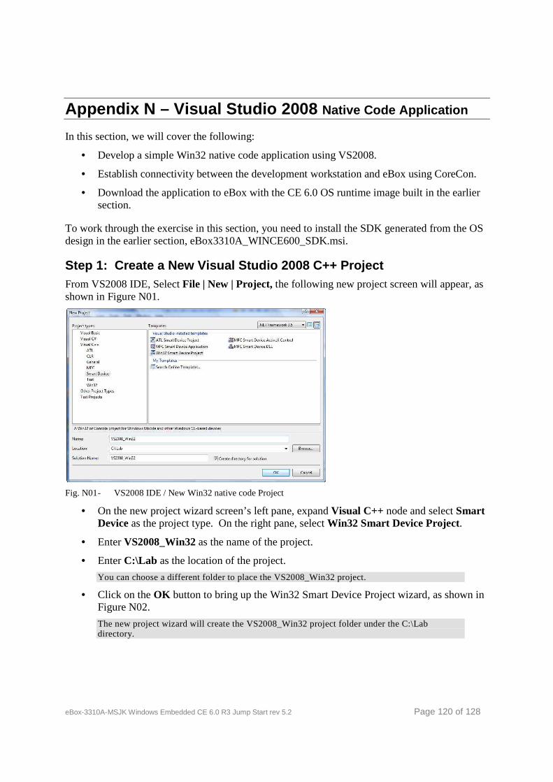
eBox-3310A-MSJK Windows Embedded CE 6.0 R3 Jump Start rev 5.2 Page 120 of 128
Appendix N – Visual Studio 2008 Native Code Application
In this section, we will cover the following:
• Develop a simple Win32 native code application using VS2008.
• Establish connectivity between the development workstation and eBox using CoreCon.
• Download the application to eBox with the CE 6.0 OS runtime image built in the earlier section.
To work through the exercise in this section, you need to install the SDK generated from the OS design in the earlier section, eBox3310A_WINCE600_SDK.msi.
Step 1: Create a New Visual Studio 2008 C++ Projec t From VS2008 IDE, Select File | New | Project, the following new project screen will appear, as shown in Figure N01.
Fig. N01 - VS2008 IDE / New Win32 native code Project
• On the new project wizard screen’s left pane, expand Visual C++ node and select Smart Device as the project type. On the right pane, select Win32 Smart Device Project.
• Enter VS2008_Win32 as the name of the project.
• Enter C:\Lab as the location of the project.
You can choose a different folder to place the VS2008_Win32 project.
• Click on the OK button to bring up the Win32 Smart Device Project wizard, as shown in Figure N02.
The new project wizard will create the VS2008_Win32 project folder under the C:\Lab directory.
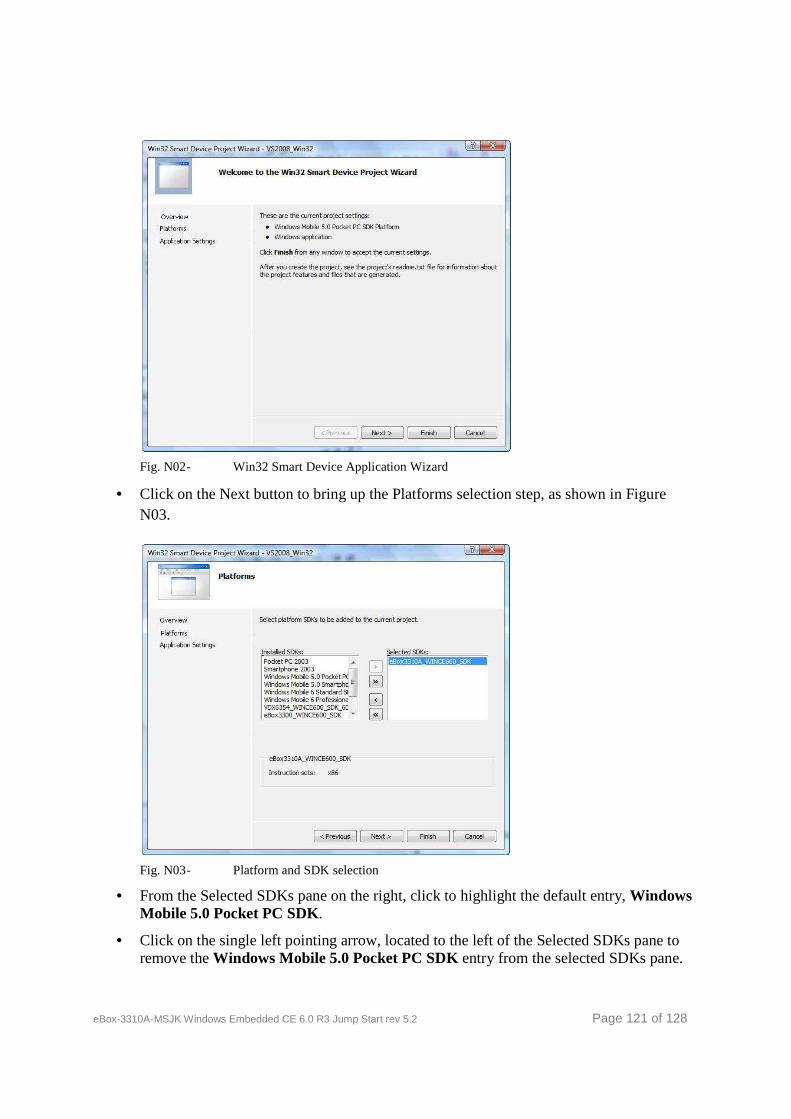
eBox-3310A-MSJK Windows Embedded CE 6.0 R3 Jump Start rev 5.2 Page 121 of 128
Fig. N02 - Win32 Smart Device Application Wizard
• Click on the Next button to bring up the Platforms selection step, as shown in Figure N03.
Fig. N03 - Platform and SDK selection
• From the Selected SDKs pane on the right, click to highlight the default entry, Windows Mobile 5.0 Pocket PC SDK.
• Click on the single left pointing arrow, located to the left of the Selected SDKs pane to remove the Windows Mobile 5.0 Pocket PC SDK entry from the selected SDKs pane.
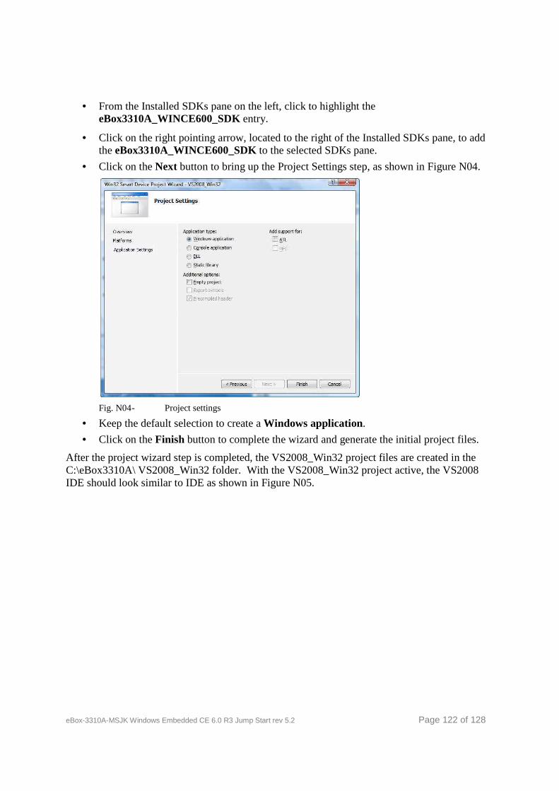
eBox-3310A-MSJK Windows Embedded CE 6.0 R3 Jump Start rev 5.2 Page 122 of 128
• From the Installed SDKs pane on the left, click to highlight the eBox3310A_WINCE600_SDK entry.
• Click on the right pointing arrow, located to the right of the Installed SDKs pane, to add the eBox3310A_WINCE600_SDK to the selected SDKs pane.
• Click on the Next button to bring up the Project Settings step, as shown in Figure N04.
Fig. N04 - Project settings
• Keep the default selection to create a Windows application.
• Click on the Finish button to complete the wizard and generate the initial project files.
After the project wizard step is completed, the VS2008_Win32 project files are created in the C:\eBox3310A\ VS2008_Win32 folder. With the VS2008_Win32 project active, the VS2008 IDE should look similar to IDE as shown in Figure N05.
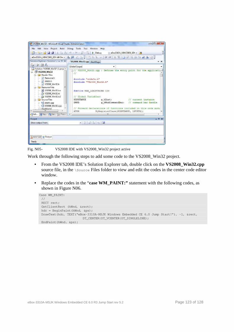
eBox-3310A-MSJK Windows Embedded CE 6.0 R3 Jump Start rev 5.2 Page 123 of 128
Fig. N05 - VS2008 IDE with VS2008_Win32 project active
Work through the following steps to add some code to the VS2008_Win32 project.
• From the VS2008 IDE’s Solution Explorer tab, double click on the VS2008_Win32.cpp source file, in the \Source Files folder to view and edit the codes in the center code editor window.
• Replace the codes in the “case WM_PAINT:” statement with the following codes, as shown in Figure N06.
Case WM_PAINT: // RECT rect; GetClientRect (hWnd, &rect); hdc = BeginPaint(hWnd, &ps); DrawText(hdc, TEXT(“eBox-3310A-MSJK Windows Embedd ed CE 6.0 Jump Start!”), -1, &rect, DT_CENTER|DT_VCENTER|DT_SINGLELINE); EndPaint(hWnd. &ps);
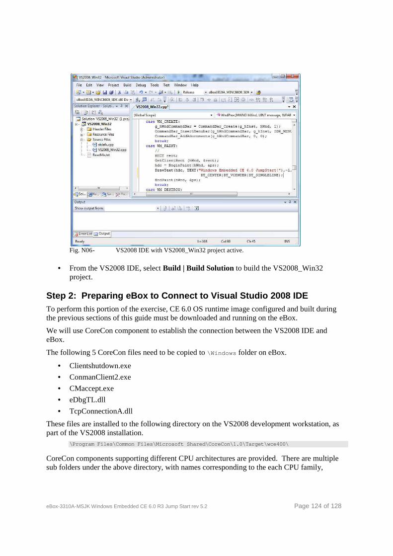
eBox-3310A-MSJK Windows Embedded CE 6.0 R3 Jump Start rev 5.2 Page 124 of 128
Fig. N06 - VS2008 IDE with VS2008_Win32 project active.
• From the VS2008 IDE, select Build | Build Solution to build the VS2008_Win32 project.
Step 2: Preparing eBox to Connect to Visual Studio 2008 IDE To perform this portion of the exercise, CE 6.0 OS runtime image configured and built during the previous sections of this guide must be downloaded and running on the eBox.
We will use CoreCon component to establish the connection between the VS2008 IDE and eBox.
The following 5 CoreCon files need to be copied to \Windows folder on eBox.
• Clientshutdown.exe
• ConmanClient2.exe
• CMaccept.exe
• eDbgTL.dll
• TcpConnectionA.dll
These files are installed to the following directory on the VS2008 development workstation, as part of the VS2008 installation.
\Program Files\Common Files\Microsoft Shared\CoreCo n\1.0\Target\wce400\
CoreCon components supporting different CPU architectures are provided. There are multiple sub folders under the above directory, with names corresponding to the each CPU family,
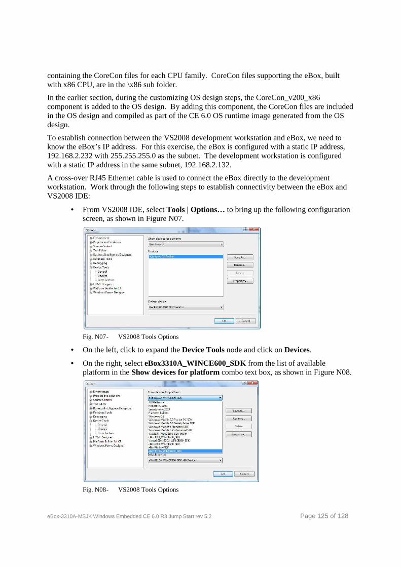
eBox-3310A-MSJK Windows Embedded CE 6.0 R3 Jump Start rev 5.2 Page 125 of 128
containing the CoreCon files for each CPU family. CoreCon files supporting the eBox, built with x86 CPU, are in the \x86 sub folder.
In the earlier section, during the customizing OS design steps, the CoreCon_v200_x86 component is added to the OS design. By adding this component, the CoreCon files are included in the OS design and compiled as part of the CE 6.0 OS runtime image generated from the OS design.
To establish connection between the VS2008 development workstation and eBox, we need to know the eBox’s IP address. For this exercise, the eBox is configured with a static IP address, 192.168.2.232 with 255.255.255.0 as the subnet. The development workstation is configured with a static IP address in the same subnet, 192.168.2.132.
A cross-over RJ45 Ethernet cable is used to connect the eBox directly to the development workstation. Work through the following steps to establish connectivity between the eBox and VS2008 IDE:
• From VS2008 IDE, select Tools | Options… to bring up the following configuration screen, as shown in Figure N07.
Fig. N07 - VS2008 Tools Options
• On the left, click to expand the Device Tools node and click on Devices.
• On the right, select eBox3310A_WINCE600_SDK from the list of available platform in the Show devices for platform combo text box, as shown in Figure N08.
Fig. N08 - VS2008 Tools Options

eBox-3310A-MSJK Windows Embedded CE 6.0 R3 Jump Start rev 5.2 Page 126 of 128
• Click on the Properties button to bring up eBox3310A_WINCE600 x86 Device Properties setting screen, as shown in Figure N09.
Fig. N09 - eBox3310A_WINCE600 x86 Device properties
• Click on the Configure button to bring up Configure TCP/IP Transport screen.
• Select Use specific IP address and enter IP address for the eBox, as shown in Figure N10.
Fig. N10 - Configure TCP/IP Transport / Set device IP Address
• Click the OK button to save device IP address setting.
• Click the OK button on the eBox3310A_WINCE600_SDK x86 Device Properties screen.
• Click the OK button on the Options screen.
Step 3: Connecting eBox to Visual Studio 2008 IDE using CoreCon To initiate connection between VS2008 IDE and eBox using CoreCon, we need to launch the ConmanClient2.exe and cMaccept.exe CoreCon components from eBox manually. This is a cumbersome process and has to perform at least once for each time the eBox reset.
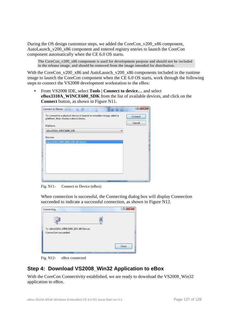
eBox-3310A-MSJK Windows Embedded CE 6.0 R3 Jump Start rev 5.2 Page 127 of 128
During the OS design customize steps, we added the CoreCon_v200_x86 component, AutoLaunch_v200_x86 component and entered registry entries to launch the CoreCon component automatically when the CE 6.0 OS starts.
The CoreCon_v200_x86 component is used for development purpose and should not be included in the release image, and should be removed from the image intended for distribution.
With the CoreCon_v200_x86 and AutoLaunch_v200_x86 components included in the runtime image to launch the CoreCon component when the CE 6.0 OS starts, work through the following steps to connect the VS2008 development workstation to the eBox:
• From VS2008 IDE, select Tools | Connect to device… and select eBox3310A_WINCE600_SDK from the list of available devices, and click on the Connect button, as shown in Figure N11.
Fig. N11 - Connect to Device (eBox)
When connection is successful, the Connecting dialog box will display Connection succeeded to indicate a successful connection, as shown in Figure N12.
Fig. N12 - eBox connected
Step 4: Download VS2008_Win32 Application to eBox With the CoreCon Connectivity established, we are ready to download the VS2008_Win32 application to eBox.
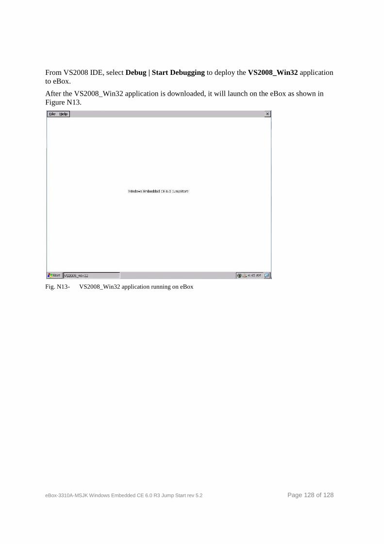
eBox-3310A-MSJK Windows Embedded CE 6.0 R3 Jump Start rev 5.2 Page 128 of 128
From VS2008 IDE, select Debug | Start Debugging to deploy the VS2008_Win32 application to eBox.
After the VS2008_Win32 application is downloaded, it will launch on the eBox as shown in Figure N13.
Fig. N13 - VS2008_Win32 application running on eBox