Embed Size (px)
Citation preview
FI9900012
POSIVA 98-03
EB-welding of the copper canisterfor the nuclear waste disposal
Final report of the developmentprogramme 1994-1997
Ha rri AaltoOutokumpu Oy Poricopper
October 1 998
POSIVA OY
M i k o n k a t u 1 5 A . F I N - 0 0 1 0 0 H E L S I N K I , F I N L A N D
P h o n e ( 0 9 ) 2 2 8 0 3 0 ( n a l . ) . ( + 3 5 8 - 9 - ) 2 2 8 0 3 O ( i n t . )
F a x ( 0 9 ) 2 2 8 0 3 7 1 9 ( n a t ) , ( + 3 5 8 - 9 - ) 2 2 8 0 3 7 1 9 ( i n t . )
ti - POSiVa Report Raportintunnus- Report codePOSIVA 98-03
Mikonkatu 15 A, FIN-00100 HELSINKI, FINLAND Juikaisuaika-DatePuh. (09) 2280 30 - Int. Tel. +358 9 2280 30 October 1998
Tekija(t) - Author(s)
Hani AaltoOutokumpu Oy Poricopper
Toimeksiantajaft) - Commissioned by
Posiva Oy
Nimeke- Title
EB-WELDING OF THE COPPER CANISTER FOR THE NUCLEAR WASTE DISPOSAL-FINAL REPORT OF THE DEVELOPMENT PROGRAMME 1994-1997
TiivistelmS - Abstract
During 1994-1997 Posiva Oy and Outokumpu Poricopper Oy had a joint project "Development ofEB-welding method for massive copper canister manufacturing". The project was part of thenational technology program "Weld 2000" and it was supported financially by TechnologyDevelopment Centre (TEKES).
The spent fuel from Finnish nuclear reactors is planned to be encapsulated in thick-walled coppercanisters and placed deep into the bedrock. The thick copper layer of the canister provides a longtime corrosion resistance and prevents deposited nuclear fuel from contact with water. The qualityrequirements of the copper components are high because of the designed long lifetime of thecanister. The EB-welding technology has proved to be applicable method for the production of thecopper canisters and the EB-welding technique is needed at least when the lids of the copper canisterwill be closed.
There are a number of parameters in EB-welding which affect weldability. However, the effectof the welding parameters and their optimization has not been extensively studied in welding of thickcopper sections using conventional high vacuum EB-welding. One aim of this development workwas to extensively study effect of welding parameters on weld quality. The final objective was tominimise welding defects in the main weld and optimize slope out procedure in thick copper EB-welding.
Welding of 50 mm thick copper sections was optimized using vertical and horizontal EB-weldingtechniques. As a result two full scale copper lids were welded to a short cylinder successfully. Theresulting weld quality with optimised welding parameters was reasonable good. The optimisedwelding parameters for horizontal and vertical beam can be applied to the longitudinal body welds ofthe canister. The optimal slope out procedure for the lid closure needs some additional developmentwork.
In addition of extensive EB-welding program ultrasonic inspection and creep strength of the weldwere studied. According to investigations the creep strength of the copper material is sufficient forrepository conditions. The ultrasonic inspection of the weld is very challenging because of large andorientated grain structure of the material. Some additional work is needed to optimise the materialgrain structure and ultrasonic probes which will be used in full scale canister inspection.
The whole research work confirm the applicability of copper as a canister material and givesgood basis on manufacture of full size canisters applying EB-welding technique.
Avainsanat - KeywordsEB-welding, copper canister, nuclear fuel disposal
ISBNISBN 951-652-041-3
SivumaSrS - Number of pages43
ISSNISSN 1239-3096
Kieli - LanguageEnglish
ti - Posiva Report Raportin tunnus "Report ° ° *POSIVA 98-03
Posiva Oy .Mikonkatu 15 A, FIN-00100 HELSINKI, FINLAND JuiKaisuaxa uatePuh. (09) 2280 30 - Int. Tel. +358 9 2280 30 Lokakuu 1998
Tekijä(t) - Author(s)
Harri AaltoOutokumpu Poricopper Oy
Toimetcsiantaja(t) - Commissioned by
Posiva Oy
Nimeke - Title
EB-HITSAUSMENETELMÄN KEHITTÄMINEN MASSIIVISEN KUPARIKAPSELINVALMISTAMISEEN-TUTKIMUSOHJELMAN LOPPURAPORTTI 1994-1997
Tiivistelmä - Abstract
Vuosina 1994-1997 toteutettiin Posiva Oy:n ja Outokumpu Poricopper Oy:n yhteistyönä menetelmä-kehitysprojekti, joka kuului osana TEKESin hitsaus- ja levytekniikan teknologiaohjelmaan. Projek-tin tavoitteena oli kehittää elektronisuihkuhitsausta hyödyntävä kuparikapselien valmistusmenetelmä.
Käytetyn ydinpolttoaineen loppusijoitus aiotaan Suomessa toteuttaa hautaamalla ne kapseloituinanoin 500 metrin syvyyteen peruskallioon. Kapselin ulkopinnalla on paksu kuparivaippa, joka antaakapselille korroosiosuojan ja estää pohjaveden pääsyn kontaktiin loppusijoitetun polttoaineenkanssa. Suunnitellusta pitkästä käyttöiästä johtuen kapselin laatuvaatimukset ovat korkeat.Elektronisuihkuhitsaus (EB-hitsaus) on osoittautunut soveltuvaksi menetelmäksi kuparikapselienvalmistuksessa ja EB-hitsausta tarvitaan ainakin kapselin kansia suljettaessa.
Hitsausparametrien vaikutusta paksun kuparin hitsaukseen ja hitsin laatuun ei ollut aikaisemminsystemaattisesti selvitetty. Projektin keskeisinä tavoitteina olivat hitsausparametrien vaikutuksenkartoitus ja mahdollisimman hyvälaatuisen hitsin saaminen paksuun kupariin. Erityisenä kehityskoh-teena oli hitsin juurialueella sijaitsevien virheiden minimointi ja hitsauksen lopetuksen optimointi.
Noin 50 mm paksuisia kuparikappaleita käyttäen optimoitiin hitsausparametrit sekä pysty- ettävaakasäteellä suoritetuilla EB-hitsauskokeilla. Projektin lopputuotteina valmistui kaksi todellisenkannen sulkemista demonstroivaa EB-hitsauskoetta, joissa täyden mittakaavan kannet liitettiinsylinterimäisiin kappaleisiin. Optimoiduissa hitseissä saavutettiin hyvät lopputulokset perushitsinalueella pysty- ja vaakasäteellä. Näitä parametrejä voidaan käyttää kuparikapselin sylinterimäisenosan pitkittäisliitosten hitsauksessa kuumavalssaukseen ja taivutukseen perustuvassa valmistus-menetelmässä. Hitsauksen lopetuksen optimointi osoittautui erittäin vaativaksi paksulle kuparille jahyvän lopputuloksen saavuttaminen vaatii vielä lisätutkimuksia.
Laajan EB-hitsausohjelman lisäksi projektin aikana selvitettiin kuparikapselin ultraäänitarkastustaja EB-hitsin virumislujuutta. Tehtyjen tutkimusten mukaan EB-hitsin virumislujuus on riittäväloppusijoitusolosuhteissa. EB-hitsin ultraäänitarkastus osoittautui erittäin haastavaksi, johtuen EB-hitsin raerakenteesta ja sen suuntautumisesta. Ultraäänitarkastuksen kehittämiseksi tarvitaan lisä-tutkimuksia sekä materiaalin sisäisen rakenteen optimoimiseksi että sopivien ultraääniantureiden jatarkastustekniikoiden soveltamiseksi täyden mittakaavan kapselin tarkastamiseen.
Koko tutkimusohjelma vahvistaa perusteita kuparin käytölle kapselimateriaalina ja antaa hyvänpohjan täyden mittakaavan kuparikapselin valmistamiselle EB-hitsausta hyväksikäyttäen.
Avainsanat - Keywords
EB-hitsaus, kupari, käytetyn ydinpolttoaineen loppusijoitusISBN
ISBN 951-652-041-3ISSN
ISSN 1239-3096
Sivumäärä - Number of pages
43Kieli - Language
EnglantiNBXT PAOB(S)
left BLANK
TABLE OF CONTENTS
Abstract 3
Tiivistelma 4
1 INTRODUCTION 9
2 CIRCULAR AND LONGITUDINAL EB-WELDSOF THICK COPPER CYLINDERS 102.1 Canister design 102.2 Difficulties with circular EB-welding 112.3 The slope out area 122.4 Weld penetration and weld profile 132.5 Welding defects and their formation mechanisms 13
3 EB-WELDING EXPERIMENTS 163.1 The objectives of the test program 163.2 Test materials 163.3 Welding equipment 173.4 Welding parameters 183.5 Experimental procedures 20
4 LID EB-WELDING 224.1 Production of the lids 224.2 Production of the cylinder parts 224.3 Horizontal beam welded lid 234.4 Vertical beam welded lid 25
5 RESULTS OF EB-WELDING PROGRAM 275.1 Weldability of different copper grades 275.2 Welding parameters and weldability 275.3 Minimisation of the root defects 285.4 Slope out procedure development 295.5 Transferability of welding parameters 295.6 Optimal welding parameters for thick copper welding 295.7 Results of demonstration welding 30
6 ULTRASONIC INSPECTION OF EB-WELD 316.1 Introduction 316.2 Materials and test program * 316.3 Ultrasonic techniques 326.4 Results of the test examination 336.5 Conclusions 34
7 CREEP PROPERTIES OF EB-WELDED COPPER 367.1 Background 367.2 Materials 367.3 Testing methods 367.4 Results 377.5 Conclusions 39
8 SUMMARY AND CONCLUSIONS 40
9 REFERENCES 41
APPENDIX 1: Horizontal beam welded lid 42APPENDIX 2: Vertical beam welded lid 43
1 INTRODUCTION
Outokumpu Poricopper Oy and Posiva Oy are doing joint research and development workin high active nuclear waste disposal techniques, specifically in copper canistermanufacturing technology. The Posiva type composite canister consists of an internal castiron insert and copper overpack of 50 mm thickness with double lids. The EB-weldingtechnique is to be applied to the canisters, since the canisters consist of at least twoEB-welds, namely the final closure of the both lids. The designed target lifetime of thecanister is 100 000 years and thus the canisters must be welded with a high regard onreliability, integrity and inspectability of the weld.
Joining of thick copper sections is not straightforward, when using existing weldingmethods due to the coppers' high thermal conductivity. Electron beam welding has beenfound to be a suitable and effective joining method for thick metals. The method can beapplied to products where preheating is not feasible. The case in point is the final closureof the copper canisters for nuclear fuel disposal.
There have been some earlier studies of EB-welding of copper elsewhere in the world.Those studies have shown that EB-welding of thick copper is very challenging, andavoiding welding defects is difficult. The typical welding defects in thick copper areporosity, root defects, lack of fusion, blowholes and run outs.
The aim of the current study was to estimate the applicability of high vacuum EB-weldingtechnology to canister manufacturing. The main goal of this program was to preparewelding parameters which can assure defect free weld in thick copper. The first studiedapplication was longitudinal welds of the canister body when the cylinder part of thecanister is manufactured by hot rolling and bending. Two EB-welds about 4-5 m long areneeded with 55-65 mm penetration for these longitudinal welds. The second studiedapplication was the final closure of the lids where two continuous welds (about 3 m long)are needed with defect free slope out of the weld.
In addition to the EB-welding development program, the NDE-technology of theEB-welded structure was studied. The aim of the NDE-studies was to estimate theinspectability of the EB-welded structure in full-scale canisters and the applicability ofultrasonic techniques to canister examination.
Creep strength of the copper was also studied. The background to these experiments wasinsufficient knowledge of behaviour of canister material in service temperature. The earlierstudies concentrated on a highly elevated temperature area where the high temperaturecreep mechanisms exist. Research work in this report was planned to concentrate on thetemperature area of 20-150 °C which sufficiently covers the service temperature of thecanister.
10
2 CIRCULAR AND LONGITUDINAL EB-WELDS OF THICKCOPPER CYLINDER
2.1 Canister design
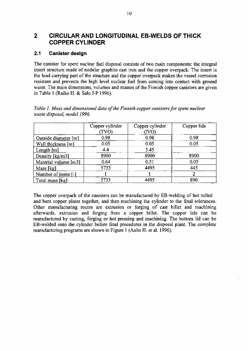
The canister for spent nuclear fuel disposal consists of two main components: the integralinsert structure made of nodular graphite cast iron and the copper overpack. The insert isthe load carrying part of the structure and the copper overpack makes the vessel corrosionresistant and prevents the high level nuclear fuel from coming into contact with groundwater. The main dimensions, volumes and masses of the Finnish copper canisters are givenin Table 1 (Raiko H. & Salo J-P 1996).
Table 1. Mass and dimensional data of the Finnish copper canisters for spent nuclearwaste disposal, model 1996.
Outside diameter \m\Wall thickness [mlLength [mlDensity [kg/m31Material volume [ni31Mass fkglNumber of items [-1Total mass [kgl
Copper cylinder(TVO)0.980.054.4
89000.645733
15733
Copper cylinder(IVO)0.980.053.4589000.514495
14495
Copper lids
L 0.980.05
89000.054452
890
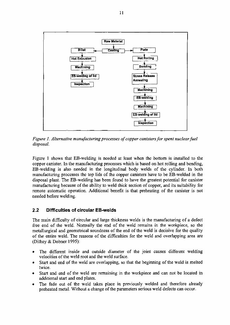
The copper overpack of the canisters can be manufactured by EB-welding of hot rolledand bent copper plates together, and then machining the cylinder to the final tolerances.Other manufacturing routes are extrusion or forging of cast billet and machiningafterwards, extrusion and forging from a copper billet. The copper lids can bemanufactured by casting, forging or hot pressing and machining. The bottom lid can beEB-welded onto the cylinder before final procedures in the disposal plant. The completemanufacturing programs are shown in Figure 1 (Aalto H. et al. 1996).
11
Billet j ^ _
1Hot Extrusion |
jMachining |
EB-welding of lid
Raw Material
+Casting
Inspection | Li
[
Plate |
*Hot Rolling
Bending [
Stress Release
Annealing
Machining
1EB-weldlng
Machining
EB-weldlng of lie
tInspection
Figure 1. Alternative manufacturing processes of copper canisters for spent nuclear fueldisposal.
Figure 1 shows that EB-welding is needed at least when the bottom is installed to thecopper canister. In the manufacturing processes which is based on hot rolling and bending,EB-welding is also needed in the longitudinal body welds of the cylinder. In bothmanufacturing processes the top lids of the copper canisters have to be EB-welded in thedisposal plant. The EB-welding has been found to have the greatest potential for canistermanufacturing because of the ability to weld thick section of copper, and its suitability forremote automatic operation. Additional benefit is that preheating of the canister is notneeded before welding.
2.2 Difficulties of circular EB-welds
The main difficulty of circular and large thickness welds is the manufacturing of a defectfree end of the weld. Normally the end of the weld remains in the workpiece, so themetallurgical and geometrical soundness of the end of the weld is decisive for the qualityof the entire weld. The reasons of the difficulties for the weld and overlapping area are(Dithey&Dobnerl995):
• The different inside and outside diameter of the joint causes different weldingvelocities of the weld root and the weld surface.
• Start and end of the weld are overlapping, so that the beginning of the weld is meltedtwice.
• Start and end of the weld are remaining in the workpiece and can not be located inadditional start and end plates.
• The fade out of the weld takes place in previously welded and therefore alreadypreheated metal. Without a change of the parameters serious weld defects can occur.
12
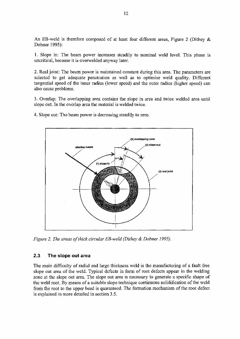
An EB-weld is therefore composed of at least four different areas, Figure 2 (Dithey &Dobner 1995):
1. Slope in: The beam power increases steadily to nominal weld level. This phase isuncritical, because it is overwelded anyway later.
2. Real joint: The beam power is maintained constant during this area. The parameters areselected to get adequate penetration as well as to optimise weld quality. Differenttangential speed of the inner radius (lower speed) and the outer radius (higher speed) canalso cause problems.
3. Overlap: The overlapping area contains the slope in area and twice welded area untilslope out. In the overlap area the material is welded twice.
4. Slope out: The beam power is decreasing steadily to zero.
electron beam
(3) overlapping zone
(4) slope-out
(2) real joint
Figure 2. The areas of thick circular EB-weld (Dithey & Dobner 1995).
2.3 The slope out area
The main difficulty of radial and large thickness weld is the manufacturing of a fault freeslope out area of the weld. Typical defects in form of root defects appear in the weldingzone at the slope out area. The slope out area is necessary to generate a specific shape ofthe weld root. By means of a suitable slope technique continuous solidification of the weldfrom the root to the upper bead is quaranteed. The formation mechanism of the root defectis explained in more detailed in section 3.5.
13
2.4 Weld penetration and weld profile
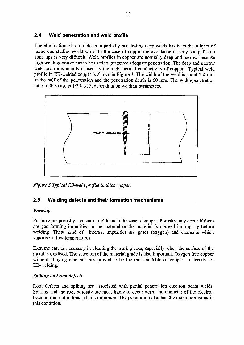
The elimination of root defects in partially penetrating deep welds has been the subject ofnumerous studies world wide. In the case of copper the avoidance of very sharp fusionzone tips is very difficult. Weld profiles in copper are normally deep and narrow becausehigh welding power has to be used to guarantee adequate penetration. The deep and narrowweld profile is mainly caused by the high thermal conductivity of copper. Typical weldprofile in EB-welded copper is shown in Figure 3. The width of the weld is about 2-4 mmat the half of the penetration and the penetration depth is 60 mm. The width/penetrationratio in this case is 1/30-1/15, depending on welding parameters.
Figure 3. Typical EB-weldprofile in thick copper.
2.5 Welding defects and their formation mechanisms
Porosity
Fusion zone porosity can cause problems in the case of copper. Porosity may occur if thereare gas forming impurities in the material or the material is cleaned improperly beforewelding. These kind of internal impurities are gases (oxygen) and elements whichvaporise at low temperatures.
Extreme care is necessary in cleaning the work pieces, especially when the surface of themetal is oxidised. The selection of the material grade is also important. Oxygen free copperwithout alloying elements has proved to be the most suitable of copper materials forEB-welding.
Spiking and root defects
Root defects and spiking are associated with partial penetration electron beam welds.Spiking and the root porosity are most likely to occur when the diameter of the electronbeam at the root is focused to a minimum. The penetration also has the maximum value inthis condition.
14
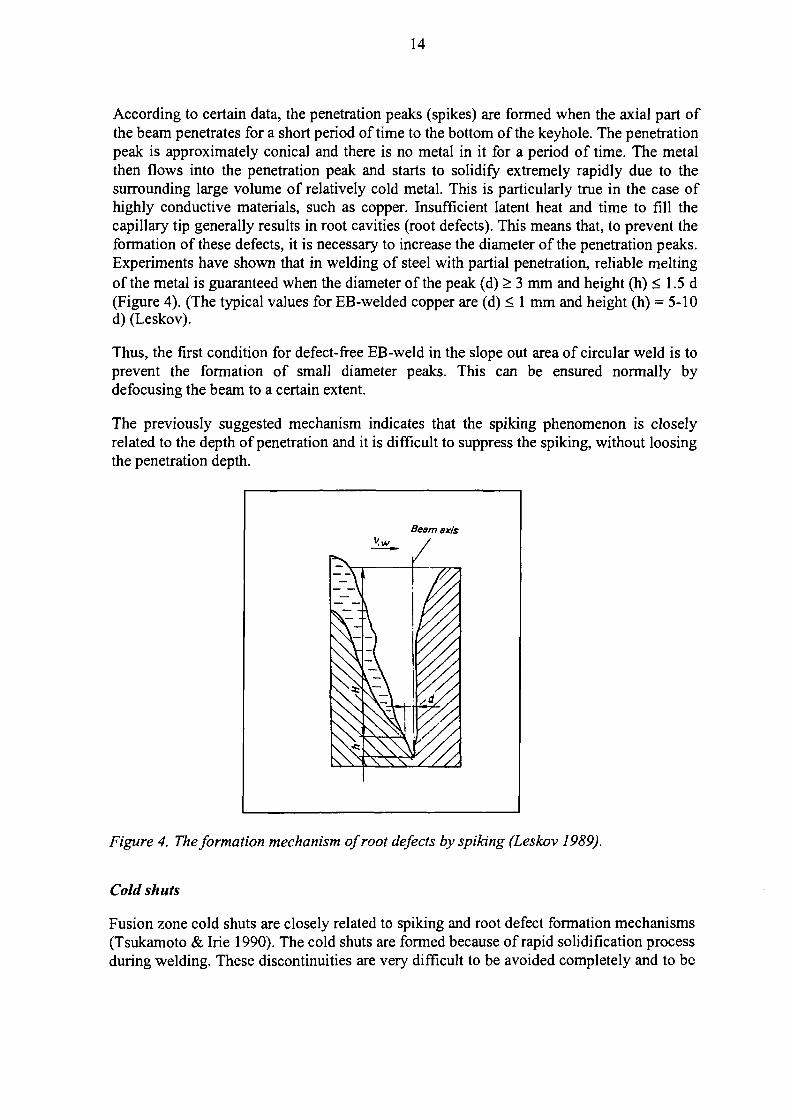
According to certain data, the penetration peaks (spikes) are formed when the axial part ofthe beam penetrates for a short period of time to the bottom of the keyhole. The penetrationpeak is approximately conical and there is no metal in it for a period of time. The metalthen flows into the penetration peak and starts to solidify extremely rapidly due to thesurrounding large volume of relatively cold metal. This is particularly true in the case ofhighly conductive materials, such as copper. Insufficient latent heat and time to fill thecapillary tip generally results in root cavities (root defects). This means that, to prevent theformation of these defects, it is necessary to increase the diameter of the penetration peaks.Experiments have shown that in welding of steel with partial penetration, reliable meltingof the metal is guaranteed when the diameter of the peak (d) > 3 mm and height (h) < 1.5 d(Figure 4). (The typical values for EB-welded copper are (d) < 1 mm and height (h) = 5-10d) (Leskov).
Thus, the first condition for defect-free EB-weld in the slope out area of circular weld is toprevent the formation of small diameter peaks. This can be ensured normally bydefocusing the beam to a certain extent.
The previously suggested mechanism indicates that the spiking phenomenon is closelyrelated to the depth of penetration and it is difficult to suppress the spiking, without loosingthe penetration depth.
Figure 4. The formation mechanism of root defects by spiking (Leskov 1989).
Cold shuts
Fusion zone cold shuts are closely related to spiking and root defect formation mechanisms(Tsukamoto & Irie 1990). The cold shuts are formed because of rapid solidification processduring welding. These discontinuities are very difficult to be avoided completely and to be
15
detected by NDE-methods in copper. Normally they cannot be detected by radiographicmethods. Ultrasonic testing can detect the larger cold shuts.
Cold shuts can usually be avoided or minimised by reducing the welding speed,broadening the weld and increaseing the radius of the weld at the root.
Run outs
The excessive run out of the molten metal can occur in the case of horizontal EB-weldingof copper. Run outs occur due to gravity and the low surface tension of the moltenmaterial. They can cause severe internal defects or craters. These defects can extend deepinto the material depending on the amount of corresponding run out.
Run outs can reduced by using a fronting bar in the case of horizontal welding or,completely avoided by welding in a vertical position.
Gun discharging
Gun discharging is not an actual welding defect, but it can cause a remarkable defect if ithappens during welding. Gun discharging (flashing) can happen when metal vapour orvapour caused by impurity elements from metal enters electron gun during welding.Vapour makes gun discharging possible. Short working distance increases the probabilityof flashing. When the gun discharging happens it produces peak or pause in the electronbeam which causes welding defects. The problem can be partly avoided using propercontrol electronics of EB-gun.
When the gun discharging happens it usually causes a deep crater which extend through thewhole penetration depth. This type of welding defect has proved to be very difficult torepair by EB-welding.
16
3 EB-WELDING EXPERIMENTS
3.1 The objectives of the test program
The main objective of the test programme was to develop the EB-welding technique whichcan be applied to longitudinal body welds of cylinder parts of the copper canister andcircular, continuous welds of the lids. The essential development target was to produce asufficiently defect free weld for the butt joints of the cylinder parts and the circular weldbetween the cylinder and the lid. The specified objectives for the research programmewere:
• prepare vertical and horizontal welds in copper without significant root defect withpenetration of 55-65 mm
• compare weldability of different copper grades• estimate effect of different welding parameters on weld quality and penetration• develop and optimise slope out procedure for vertical and horizontal EB-welding• compare welding results using horizontal and vertical beam• collect information for welding cylindrical copper pieces• estimate transferability of welding parameters from EB-welding equipment to another
3.2 Test materials
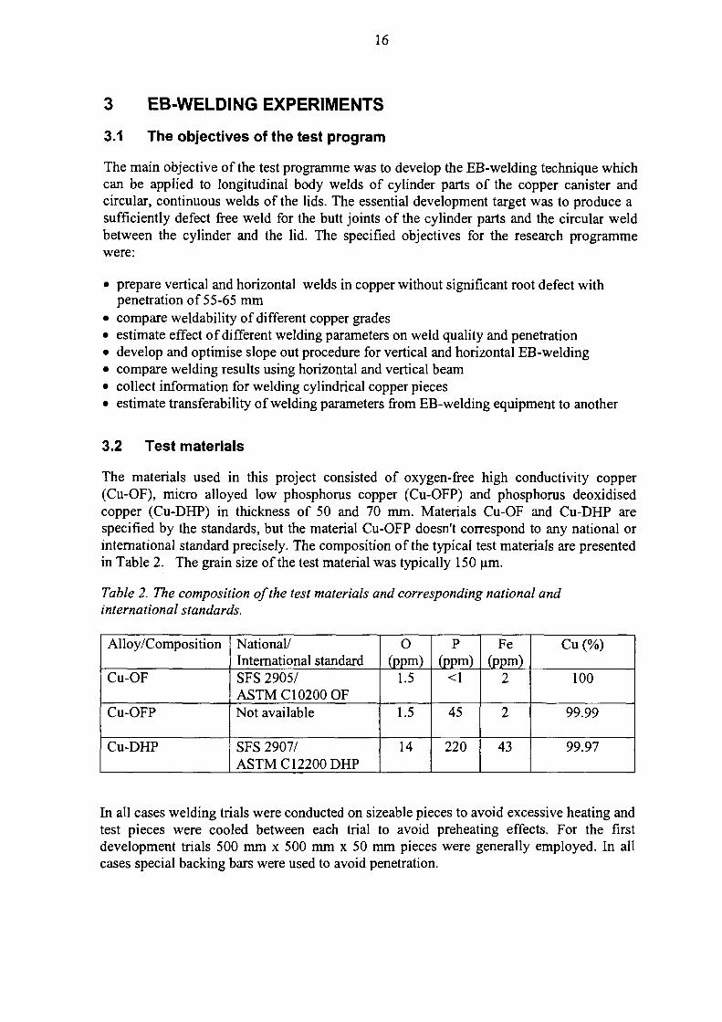
The materials used in this project consisted of oxygen-free high conductivity copper(Cu-OF), micro alloyed low phosphorus copper (Cu-OFP) and phosphorus deoxidisedcopper (Cu-DHP) in thickness of 50 and 70 mm. Materials Cu-OF and Cu-DHP arespecified by the standards, but the material Cu-OFP doesn't correspond to any national orinternational standard precisely. The composition of the typical test materials are presentedin Table 2. The grain size of the test material was typically 150 urn.
Table 2. The composition of the test materials and corresponding national andinternational standards.
Alloy/Composition
Cu-OF
Cu-OFP
Cu-DHP
National/International standardSFS 2905/ASTMC10200 OFNot available
SFS 2907/ASTMC12200DHP
O(ppm)
1.5
1.5
14
P(ppm)
<1
45
220
Fe(ppm)
2
2
43
Cu (%)
100
99.99
99.97
In all cases welding trials were conducted on sizeable pieces to avoid excessive heating andtest pieces were cooled between each trial to avoid preheating effects. For the firstdevelopment trials 500 mm x 500 mm x 50 mm pieces were generally employed. In allcases special backing bars were used to avoid penetration.
17
3.3 Welding equipment
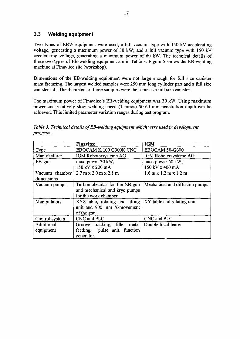
Two types of EBW equipment were used; a full vacuum type with 150 kV acceleratingvoltage, generating a maximum power of 30 kW; and a full vacuum type with 150 kVaccelerating voltage, generating a maximum power of 60 kW. The technical details ofthese two types of EB-welding equipment are in Table 3. Figure 5 shows the EB-weldingmachine at Finavitec site (workshop).
Dimensions of the EB-welding equipment were not large enough for full size canistermanufacturing. The largest welded samples were 250 mm long cylinder part and a full sizecanister lid. The diameters of these samples were the same as a full size canister.
The maximum power of Finavitec's EB-welding equipment was 30 kW. Using maximumpower and relatively slow welding speed (1 mm/s) 50-60 mm penetration depth can beachieved. This limited parameter variation ranges during test program.
Table 3. Technical details of EB-welding equipment which were used in developmentprogram.
TypeManufacturerEB-gun
Vacuum chamberdimensionsVacuum pumps
Manipulators
Control systemAdditionalequipment
FinavitecEBOCAM K 100 G300K CNCIGM Robotersysteme AGmax. power 30 kW,150 kVx 200 mA2.7mx2.0mx2.1 m
Turbomolecular for the EB-gunand mechanical and kryo pumpsfor the work chamber.XYZ-table, rotating and tiltingunit and 900 mm X-movementof the gun.CNC and PLCGroove tracking, filler metalfeeding, pulse unit, functiongenerator.
IGMEBOCAM 50-G600IGM Robotersysteme AGmax. power 60 kW;150 kVx 400 mA1.6 mx 1.2 m x 1.2 m
Mechanical and diffusion pumps
XY-table and rotating unit.
CNC and PLCDouble focal lenses

18
Figure 5. The EB-welding machine (Finavitec Oy, Finland).
3.4 Welding parameters
EBW has more parameters to control than many conventional welding process. Care mustbe taken in the control of these parameters, as variations result in significant changes in theweld. Thus, variations in weld penetration, from machine to machine or on the samewelding machine over time, can often be traced to small differences in power density.Consequently, in critical applications, care must be taken to ensure filament installation,chamber pressure, beam deflection, and gun-to-work distance are maintained constant.Major and minor welding parameters are reviewed in this section and they can be dividedto primary and secondary parameters, respectively (ANSI/AWS C7.1-92, 1992).
Accelerating voltage
Accelerating voltage is a primary welding parameter. Increasing the voltage in the electronbeam gun increases the speed of the electrons. Thus with higher voltages and higherelectron speed, it is possible to obtain a narrower beam and a sharper focus which increasesdeeper penetration of the weld for a given power.
Beam current
Beam current is also a primary welding parameter and it contributes to both the powerinput and the power density. Slope in and slope out areas are most commonlyaccomplished by variations in the beam current. It is therefore necessary to control beamcurrent during slope in and slope out. It is important that during this phase, parameters arecontrolled accurately in order that the required weld quality is maintained.
19
Focus current
The current in the focus coil is a primary parameter because of it's effect on the beam focalspot. This variable has the greatest effect on the power density at the work surface becauseit changes the area over which the beam power acts. It is advisable that a standard methodfor determining and controlling the focus current is developed and followed. It is alsoimportant to realise that the actual focal point moves up and down with changes in beamcurrent.
Welding speed
As with any welding process, travel speed is a primary welding parameter. It determinesthe power input per unit length of weld, and has a direct effect on weld joint penetrationand weld profile. Like the other primary variables it should be controlled closely tomaintain consistency in the welds produced.
The slower the velocity, the deeper is the penetration. But if the velocity is too low, theentire work piece may heat up and excessive heating can produce welding defects.
Oscillation frequency
Oscillation frequency varies from a fraction of a hertz when using the deflection togenerate the weld travel path to thousands of hertzs when using beam deflection to modifythe weld shape. The oscillation frequency is generally secondary parameter whenmodifying the weld shape.
Oscillation amplitude
Amplitude has a pronounced effect on the resulting weld. It controls the area over whichthe beam energy is distributed.
Oscillation pattern
Oscillation pattern has a significant effect on the weld. Common patterns are circular,sinusoidal (both transverse and longitudinal to the weld travel direction), and elliptical.
Gun-to-work distance
Gun-to-work distance is another secondary variable. Variations in the gun-to-work distancevaries the focal spot, and thus the beam power density. Large changes in the gun-to-workdistance has an effect on the minimum focal spot size achieved. The minimum focal spot isachieved at minimum gun-to-work distance. Also the penetration depth has the highestpossible value when the gun-to-work distance is at minimum. However, short gun-to-workdistance increases the probability to gun discharge.
Vacuum
The vacuum in the welding chamber has different effects on the welds produced. In thecase of medium vacuum welding, variations in chamber pressure, particularly above 10~2
torr (1.3 mbar) have a pronounced effect on the weld penetration and weld shape.
20
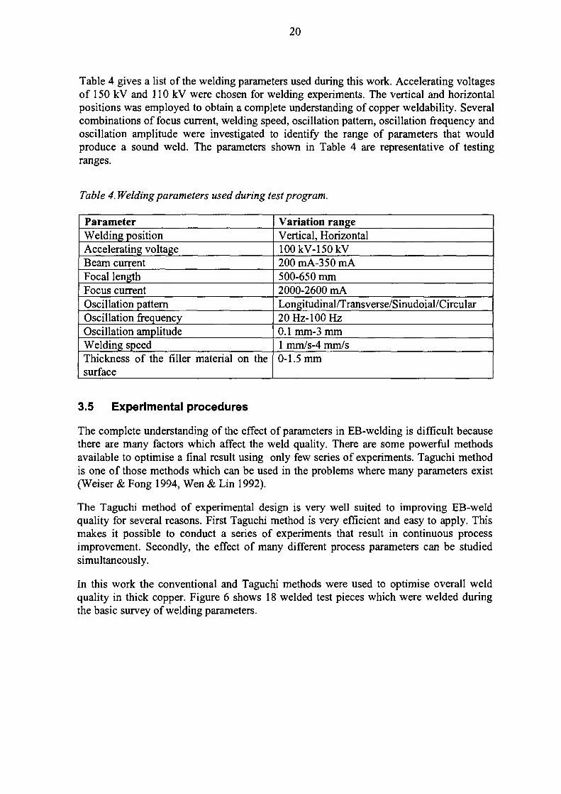
Table 4 gives a list of the welding parameters used during this work. Accelerating voltagesof 150 kV and 110 kV were chosen for welding experiments. The vertical and horizontalpositions was employed to obtain a complete understanding of copper weldability. Severalcombinations of focus current, welding speed, oscillation pattern, oscillation frequency andoscillation amplitude were investigated to identify the range of parameters that wouldproduce a sound weld. The parameters shown in Table 4 are representative of testingranges.
Table 4. Welding parameters used during test program.
ParameterWelding positionAccelerating voltageBeam currentFocal lengthFocus currentOscillation patternOscillation frequencyOscillation amplitudeWelding speedThickness of the filler material on thesurface
Variation rangeVertical, Horizontal100kV-150kV200 mA-350 mA500-650 mm2000-2600 mALongitudinal/Transverse/Sinudoial/Circular20 Hz-100 Hz0.1 mm-3 mm1 mm/s-4 mm/s0-1.5 mm
3.5 Experimental procedures
The complete understanding of the effect of parameters in EB-welding is difficult becausethere are many factors which affect the weld quality. There are some powerful methodsavailable to optimise a final result using only few series of experiments. Taguchi methodis one of those methods which can be used in the problems where many parameters exist(Weiser & Fong 1994, Wen & Lin 1992).
The Taguchi method of experimental design is very well suited to improving EB-weldquality for several reasons. First Taguchi method is very efficient and easy to apply. Thismakes it possible to conduct a series of experiments that result in continuous processimprovement. Secondly, the effect of many different process parameters can be studiedsimultaneously.
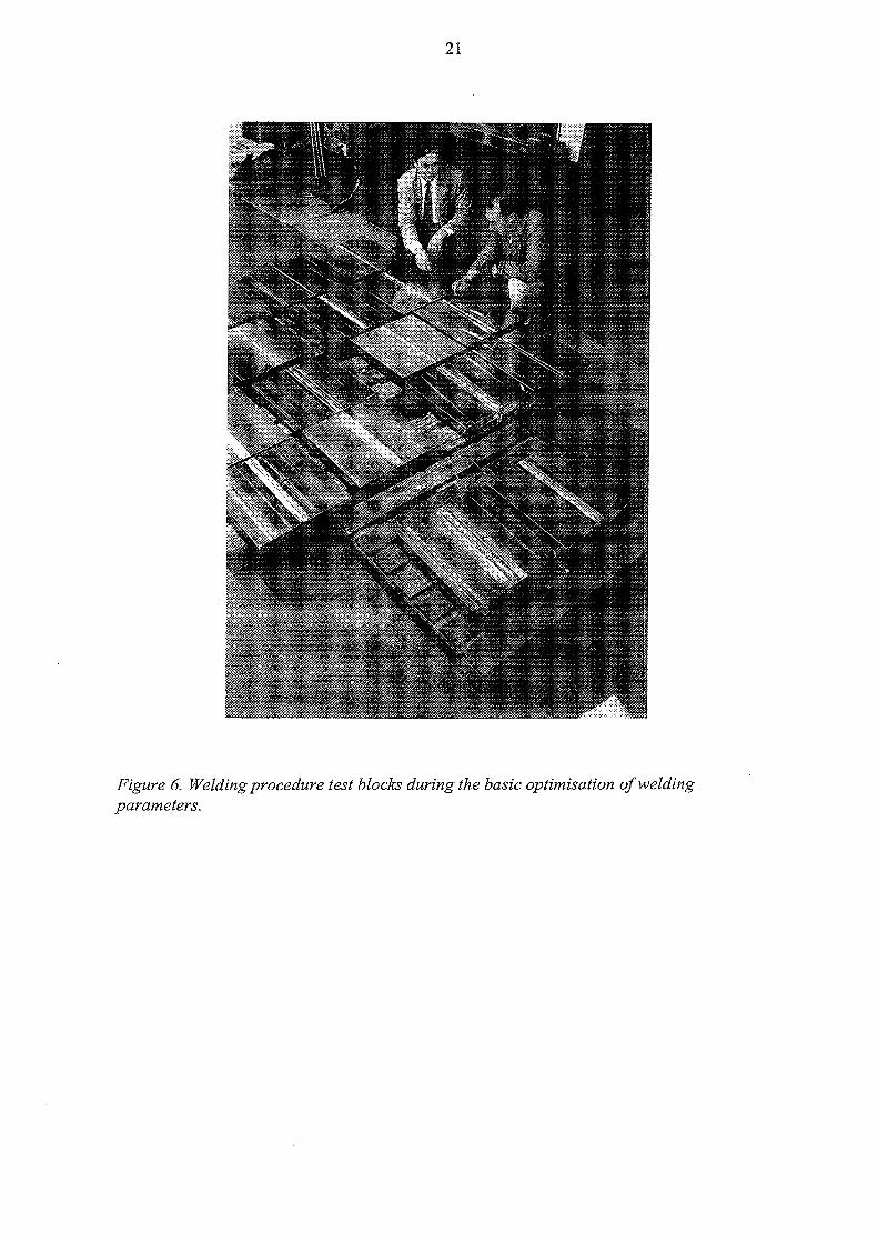
In this work the conventional and Taguchi methods were used to optimise overall weldquality in thick copper. Figure 6 shows 18 welded test pieces which were welded duringthe basic survey of welding parameters.
21
Figure 6. Welding procedure test blocks during the basic optimisation of weldingparameters.
22
4 LID EB-WELDING
4.1 Production of the lids
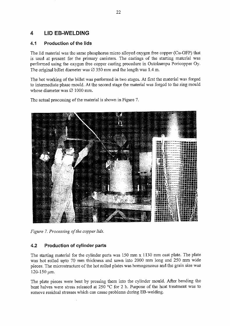
The lid material was the same phosphorus micro alloyed oxygen free copper (Cu-OFP) thatis used at present for the primary canisters. The castings of the starting material wasperformed using the oxygen free copper casting procedure in Outokumpu Poricopper Oy.The original billet diameter was 0 350 mm and the length was 1.4 m.
The hot working of the billet was performed in two stages. At first the material was forgedto intermediate phase mould. At the second stage the material was forged to the ring mouldwhose diameter was 0 1000 mm.
The actual processing of the material is shown in Figure 7.
Figure 7. Processing of the copper lids.
4.2 Production of cylinder parts
The starting material for the cylinder parts was 150 mm x 1130 mm cast plate. The platewas hot rolled upto 70 mm thickness and sawn into 2000 mm long and 250 mm widepieces. The microstructure of the hot rolled plates was homogeneous and the grain size was120-150 jam.
The plate pieces were bent by pressing them into the cylinder mould. After bending thebent halves were stress released at 250 °C for 2 h. Purpose of the heat treatment was toremove residual stresses which can cause problems during EB-welding.
23
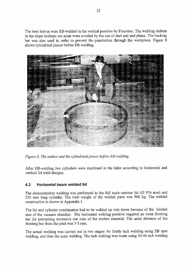
The bent halves were EB-welded in the vertical position by Finavitec. The welding defectsin the slope in/slope out areas were avoided by the use of start and end plates. The backingbar was also used in order to prevent the penetration through the workpiece. Figure 8shows cylindrical pieces before EB-welding.
Figure 8. The author and the cylindrical pieces before EB-welding.
After EB-welding two cylinders were machined in the lathe according to horizontal andvertical lid weld designs.
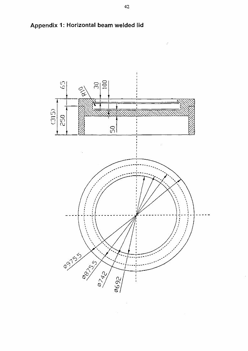
4.3 Horizontal beam welded lid
The demonstration welding was performed to the full scale canister lid ( 0 976 mm) and250 mm long cylinder. The total weight of the welded parts was 900 kg. The weldedconstruction is shown in Appendix 1.
The lid and cylinder combination had to be welded up side down because of the limitedsize of the vacuum chamber. The horizontal welding position required an outer frontingbar for preventing excessive ran outs of the molten material. The axial distance of thefronting bar from the joint was 3-5 mm.
The actual welding was carried out in two stages: by firstly tack welding using EB spotwelding, and then the main welding. The tack welding was made using 30-40 mA welding
24
current and 20 mm/s welding speed. The main welding was performed using parameters inthe Table 4.
Table 4. Welding parameters for horizontal lid welding.
Welding parameterAccelerating voltageBeam currentFocus currentWelding speedOscillation patternOscillation frequencyOscillation amplitudeWorking distance
Set valuellOkV320 mA2162 mA2 mm/sLongitudinal20 Hz1 mm530 mm
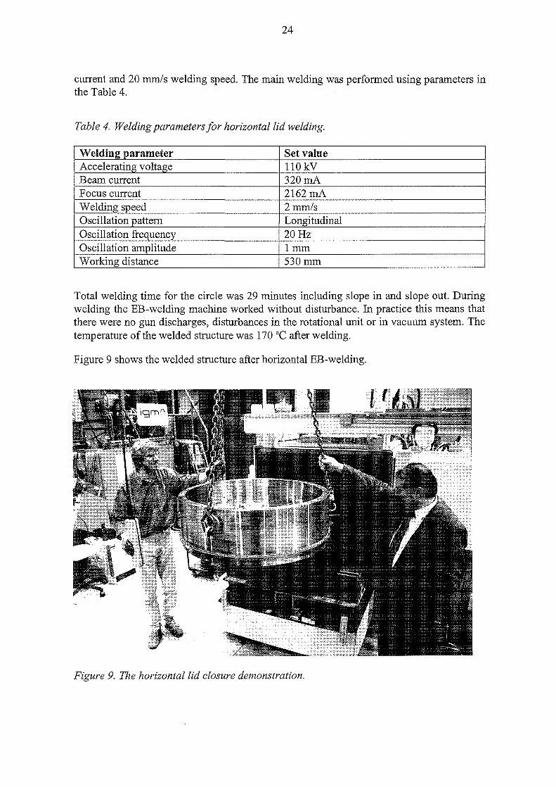
Total welding time for the circle was 29 minutes including slope in and slope out. Duringwelding the EB-welding machine worked without disturbance. In practice this means thatthere were no gun discharges, disturbances in the rotational unit or in vacuum system. Thetemperature of the welded structure was 170 °C after welding.
Figure 9 shows the welded structure after horizontal EB-welding.
Figure 9. The horizontal lid closure demonstration.
25
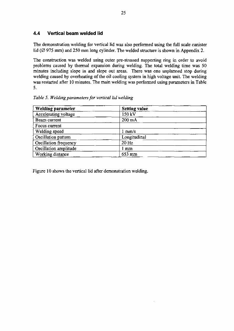
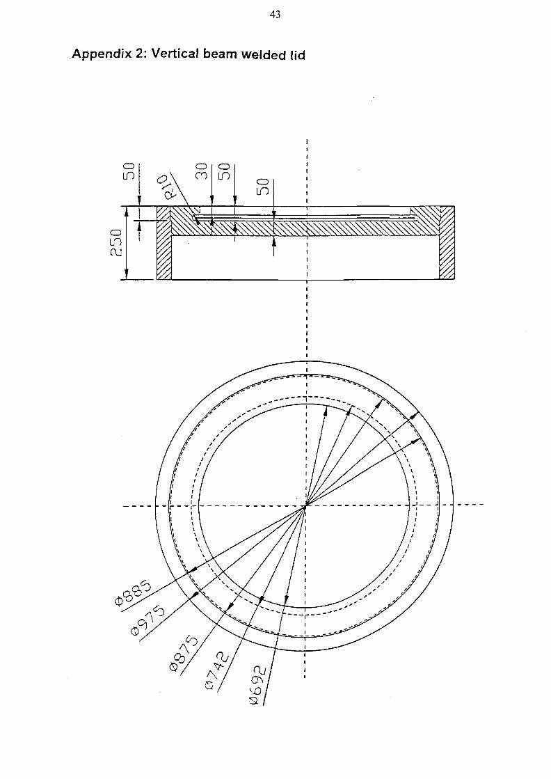
4.4 Vertical beam welded lid
The demonstration welding for vertical lid was also performed using the full scale canisterlid ( 0 975 mm) and 250 mm long cylinder. The welded structure is shown in Appendix 2.
The construction was welded using outer pre-stressed supporting ring in order to avoidproblems caused by thermal expansion during welding. The total welding time was 50minutes including slope in and slope out areas. There was one unplanned stop duringwelding caused by overheating of the oil cooling system in high voltage unit. The weldingwas restarted after 10 minutes. The main welding was performed using parameters in Table5.
Table 5. Welding parameters for vertical lid welding
Welding parameterAccelerating voltageBeam currentFocus currentWelding speedOscillation patternOscillation frequencyOscillation amplitudeWorking distance
Setting value150 kV200 mA
1 mm/sLongitudinal20 Hz1 mm653 mm
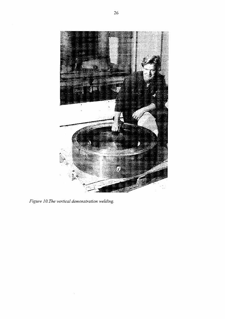
Figure 10 shows the vertical lid after demonstration welding.
26
Figure 10. The vertical demonstration welding.
27
5 RESULTS OF EB-WELDING PROGRAM
5.1 Weldability of different copper grades
After welding three base materials, each having different composition (described in TableI), the welds were inspected by non-destructive testing such as ultrasonic and radiographictests (UT,RT). Also destructive testing was used to determinate weld quality.
According to the results the welded copper grades can be divided in two categories. In thefirst group there are Cu-OF and Cu-OFP whose weldability is good. Another group isCu-DHP whose weldability is poor because the weld exhibited excessive porosity. Theporosity is caused mainly by higher oxygen content of Cu-DHP comparing to other gradesCu-OF and Cu-OFP.
5.2 Welding parameters and weldability
Accelerating voltage
High accelerating voltages (110 kV and 150 kV) have been used to achieve the requiredpenetration (55-65 mm). The use of high voltage, in connection with high beam currentand slow welding speed causes a deep and narrow weld profile which is susceptable to rootdefects and spiking. However the optimised parameters can guarantee relatively good weldquality even though high accelerating voltage is used.
Beam current
Adequate penetration is ensured by the beam current when the accelerating voltage isconstant. Thus the beam current is not normally adjusted during main welding.
The beam current is the important control variable during slope out. Investigations haveshowed that the selection of appropriate time function (linear, square, ...) is of littlesignificance. The more important thing is reducing speed of welding. During downwardadjustment of beam current full penetration welding changes into partial penetrationwelding. This change requires a sudden variation of the other welding parameters (such asfocus current, oscillation amplitude).
Welding speed
The welding speed has effect on weld profile. If slow welding speed is used wider profileof the weld can be achieved. In a case of higher welding speed the profile becomesnarrower. The narrow profile of the weld causes difficulties because it can cause rootdefects or lack of fusion.
Focus current
Focus current affects focus position and thus it is very essential parameter in determingweld quality. Esentially focus current effects the root area of the weld, because the focusposition defines the profile of the weld.
28
In the slope out area focus current is normally increased simultaneously during reductionof the beam current. The minor adjustment of the focus current during slope out does notimprove the weld quality.
Working distance
The working distance effects on penetration because it influences the energy distribution ofthe beam. Using shorter working distance more intensive energy distribution can beachieved than when using longer distances.
Vacuum pressure
The vacuum pressure used during welding is of minor importance on weld quality. Thehigh vacuum (10^ mbar) and the rough vacuum (102 mbar) were compared during testprogram.
Oscillation pattern
Welding experiments performed using vertical and horizontal beam positions showed thatlongitudinal oscillation which is parallel to the joint is most suitable for thick copperwelding. There were some minor differences in oscillation patterns but particularly for theroot quality of the weld, the longitudinal oscillation proved to be the most suitable.
Oscillation frequency
Different oscillation frequencies were also studied using both vertical and horizontalwelding. The high oscillation frequencies reduced defects at the root area but increasedmicroporosity in the weld. Microporosity increased as the frequency increased.
Oscillation amplitude
The most suitable oscillation amplitude for vertical and horizontal welding was 1.0 mmamplitude. During slope out, modifications in the oscillation amplitude didn't improve theweld quality.
Filler material
Filler material was used in order to avoid surface crater formation during welding. Thesurface defects can be reduced by filler metal but adjusting extra pieces on the surface ofthe work piece can be difficult. An alternative and well working method is a cosmetic passafter main welding.
5.3 Minimization of the root defects
One of the major objectives of the test program was to develop defect free root area in thethick copper. The results of the numerous test welds showed that it is possible to weldsignificantly defect free root area using vertical EB-welding, and optimised weldingparameters.
29
The horizontal welding position caused more welding defects especially in the root area.The welding results showed quite unsatisfactory results in the slope out area. However, theroot defects were below 50 mm penetration if sufficiently high beam current is used.Horizontal welding can therefore be applied to the construction where slope out area is inthe end plate, outside of the real joint.
The welding results of the test program can be applied to full scale copper canistermanufacturing, using either vertical or horizontal welding positions. These parameters canbe used on the longitudinal body welds of the canister manufacturing process which isbased on hot rolling and bending. In the case of vertical and horizontal EB-welding, it isrecommended to use a special backing bar in order to avoid problems caused by excessiverun outs and possible root defects. The backing bar can be machined off after EB-welding.
5.4 Slope out procedure development
The slope out area technique proved to be very challenging to develop. It is difficult toavoid root area defects especially while beam power is decreased. During the test programboth vertical and horizontal slope out techniques were developed. Generally horizontalslope out development proved to be much more difficult than the vertical one. Root areaalso defects occurred during vertical EB-welding.
However, the authors later applied new slope out procedure techniques in Finavitec.Preliminary results were very promising in the vertical position. The slope out area waspractically defect free. These tests will be reported later.
5.5 Transferability of welding parameters
The EB-welding machines of Finavitec and IGM are technically relatively close to eachother. The parameters proved to behave quite similarly in both machines.
Accordingly the welding results using the same parameters on differen machines gavealmost identical welding results. Thus it can be concluded that transferability was excellentin this particular case, altough generally it can be more difficult to transfer parameters fromone machine to another because of differences in gun power, electronics and beamgenerating devices.
5.6 Optimal welding parameters for thick copper welding
Optimising welding parameters for thick copper requires a lot of work. There is not one setof parameters which can be applied in all cases. The horizontal and vertical EB-weldingrequires different set of parameters for optimal welding. The optimal set of parameters isalso dependent on the characteristics of the EB-welding machine.
Every time a new set of welding procedure tests is required, if there is a change in thecopper material or thickness to be welded by EBW.
30
5.7 Results of demonstration welding
Results of demonstration welding showed that it is possible to weld the lid closure in eithera vertical or horizontal position. The general quality of the welded structure was better inthe vertical weld but the machining and installation of the lid with vertical weld is morecomplex than the one with horizontal weld.
The horizontal welding position caused excessive run outs and defects on root area. Therun outs can be reduced by using outer fronting ring but according to the welding tests it isvery difficult to avoid them completely.
31
6 ULTRASONIC INSPECTION OF EB-WELD
6.1 Introduction
The weld between the canister and the lid has to be inspected after welding in order to besure that no significant defects are existing in the weld. The aim of the ultrasonicinspection was to study the applicability of ultrasonic techniques for inspection ofEB-welds in copper. Practical examinations were performed with several specimenssimulating the real weld geometry in the copper canister. The first simplified specimenscontaining artificial reflectors were used to test different ultrasonic techniques and tooptimise the transducers used in later experiments. The final tests were performed with aspecimen representing full size inspection of the EB-weld between lid and canister(Jeskanen & Kauppinen 1997).
Typical welding defects in copper are root defects, incomplete penetration, lack of fusionand craters. The purpose of the inspection programme was to assess the observation to beable to detect defects in EB-welded thick copper.
6.2 Materials and test program
The test material which has been used in all ultrasonic experiments is Cu-OFP. Specifiedcomposition of the Cu-OFP is shown in Table 1.
The ultrasonic examinations were performed using three different test specimens. The firstspecimen was a hot rolled copper plate containing an EB-weld. The grain size of the platewas 120-150
The two following specimens were manufactured according to real canister geometrywhich is shown in Figure 10. The EB-weld geometry simulated the geometry of the realcopper canister. The specimens also contain two different microstructures: lid side of thespecimen is hot forged and, cylinder side is hot rolled. The grain size of the hot forged sidewas 500-1500 (am and on the hot rolled side 120-150
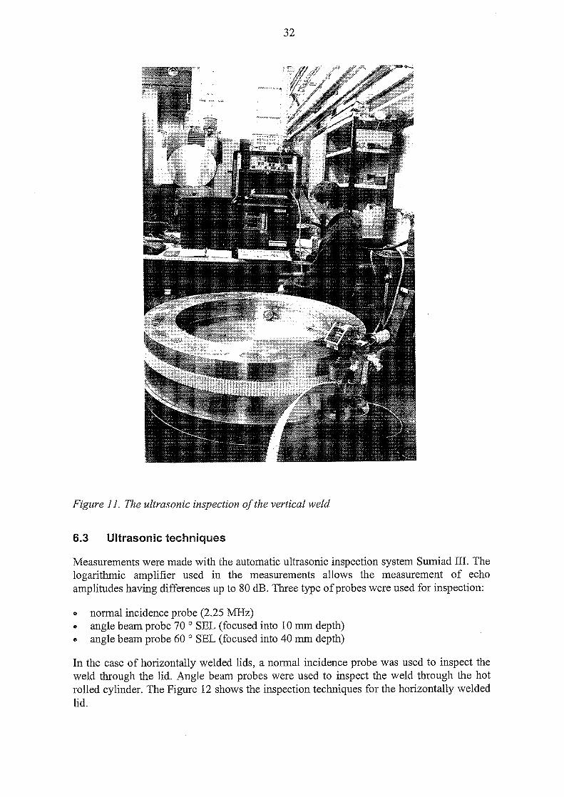
The final inspection was performed on a full size canister lid which is shown in Figure 11.The lid was manufactured by hot pressing and the grain size of the lid was 150-200The cylinder was fabricated from hot rolled plate whose grain size was 120-150 fim.
32
Figure 11. The ultrasonic inspection of the vertical weld
6.3 Ultrasonic techniques
Measurements were made with the automatic ultrasonic inspection system Sumiad III. Thelogarithmic amplifier used in the measurements allows the measurement of echoamplitudes having differences up to 80 dB. Three type of probes were used for inspection:
» normal incidence probe (2.25 MHz)«• angle beam probe 70 ° SEL (focused into 10 mm depth)» angle beam probe 60 ° SEL (focused into 40 mm depth)
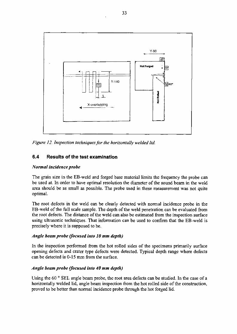
In the case of horizontally welded lids, a normal incidence probe was used to inspect theweld through the lid. Angle beam probes were used to inspect the weld through the hotrolled cylinder. The Figure 12 shows the inspection techniques for the horizontally weldedlid.
33
Y-90
L'HY-140
X-overlapping
Hot Forged
Figure 12. Inspection techniques for the horizontally welded lid.
6.4 Results of the test examination
Normal incidence probe
The grain size in the EB-weld and forged base material limits the frequency the probe canbe used at. In order to have optimal resolution the diameter of the sound beam in the weldarea should be as small as possible. The probe used in these measurement was not quiteoptimal.
The root defects in the weld can be clearly detected with normal incidence probe in theEB-weld of the full scale sample. The depth of the weld penetration can be evaluated fromthe root defects. The distance of the weld can also be estimated from the inspection surfaceusing ultrasonic techniques. That information can be used to confirm that the EB-weld isprecisely where it is supposed to be.
Angle beam probe (focused into 10 mm depth)
In the inspection performed from the hot rolled sides of the specimens primarily surfaceopening defects and crater type defects were detected. Typical depth range where defectscan be detected is 0-15 mm from the surface.
Angle beam probe (focused into 40 mm depth)
Using the 60 ° SEL angle beam probe, the root area defects can be studied. In the case of ahorizontally welded lid, angle beam inspection from the hot rolled side of the construction,proved to be better than normal incidence probe through the hot forged lid.
34
Horizontally and vertically welded lids
Comparison was performed using both the horizontal and vertical welded structures. Thevertically welded construction proved to be easier to inspect than the horizontal one, usingultrasonic testing. The major difference in the inspectability of the vertical and horizontalconstruction was mainly caused by the direction used in scanning with the normalincidence probe. In the case of vertical welded construction the scanning was performedthrough the hot rolled plate (having smaller grain size than the hot forged lid wheninspection was performed to the horizontally welded lid).
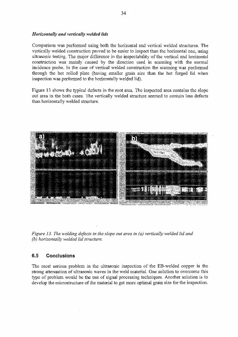
Figure 13 shows the typical defects in the root area. The inspected area contains the slopeout area in the both cases. The vertically welded structure seemed to contain less defectsthan horizontally welded structure.
Figure 13. The welding defects in the slope out area in (a) vertically welded lid and(b) horizontally welded lid structure.
6.5 Conclusions
The most serious problem in the ultrasonic inspection of the EB-welded copper is thestrong attenuation of ultrasonic waves in the weld material. One solution to overcome thistype of problem would be the use of signal processing techniques. Another solution is todevelop the microstructure of the material to get more optimal grain size for the inspection.
35
For the inspection, focused normal incidence probes and focused angle beam probes arerecommended. Based on the experimental results it can be estimated that in the EB-weld,planar structural discontinuities having a diameter larger than 5 mm and locatingperpendicular to the sound beam, can be reliably detected. Based on inspection of the fullscale sample it could be assessed that even smaller defects can be detected.
With the normal incidence probe the root defects in the weld can be revealed and based onthese, the depth and the distance of the EB-weld from the inspection surface can beassessed.
Comparisons performed between horizontal and vertical welded lid structures, proved thatvertically welded structure contains less welding defects, and is also easier to inspect byultrasonic than the horizontal structure.
36
7 CREEP PROPERTIES OF EB-WELDED COPPER
7.1 Background
The aim of the present work was to produce an experimentally based assessment of thelong-term strength and performance of the copper lid welds in the nuclear waste disposalcanister.
The EB-welds tends to be weaker than the base material under long term creep loading ofpolycrystalline metals, due to aspects related to the microstructure even when there are noactual weld defects. It is therefore of considerable interest to explore the effect of welds onthe expected life of the welded copper lids under the expected ranges of temperature andstress. Earlier performed creep experiments were made in highly elevated temperatures andthe present work aimed to study creep strength closer to the expected temperature thatwould occur in the repository (Auerkari & Holstrom 1997).
7.2 Materials
The test material was Cu-OFP whose composition is presented in the Table 1. Samples forcreep testing were sawn from the original weld test plates and machined to the uniaxialspecimens.
7.3 Testing methods
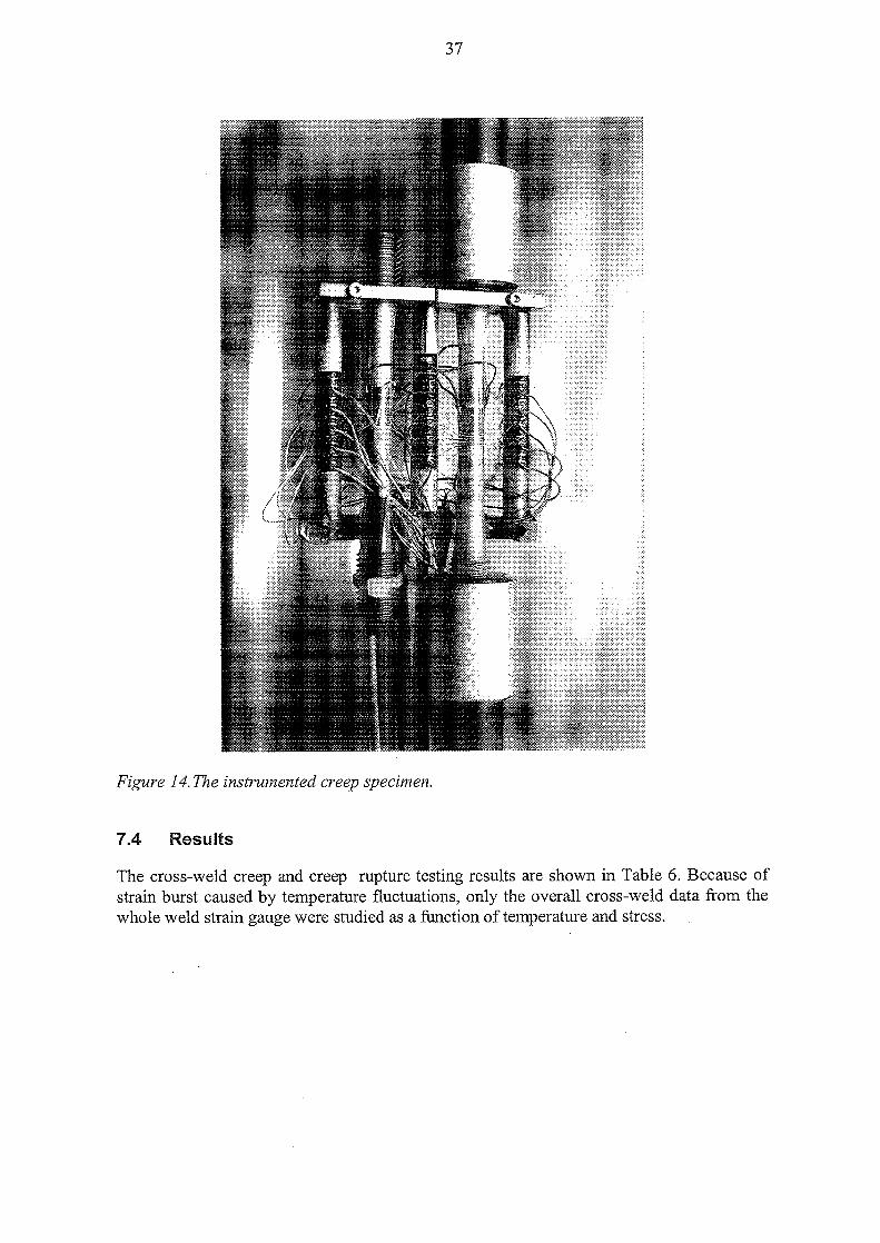
Creep testing was performed in 20 kN lever type constant load creep testing machine byVTT within the temperature range of 20 to 150 °C (one test at 200 °C). Most of the testswere designed to give failure within about 5000 h (max). In addition, tests were performedat very low stresses with specimens instrumented with strain gauges over different zones ofthe weld as well as across the whole weld. The instrumented specimen is shown in Figure14.
37
Figure 14. The instrumented creep specimen.
7.4 Results
The cross-weld creep and creep rupture testing results are shown in Table 6. Because ofstrain burst caused by temperature fluctuations, only the overall cross-weld data from thewhole weld strain gauge were studied as a function of temperature and stress.
38
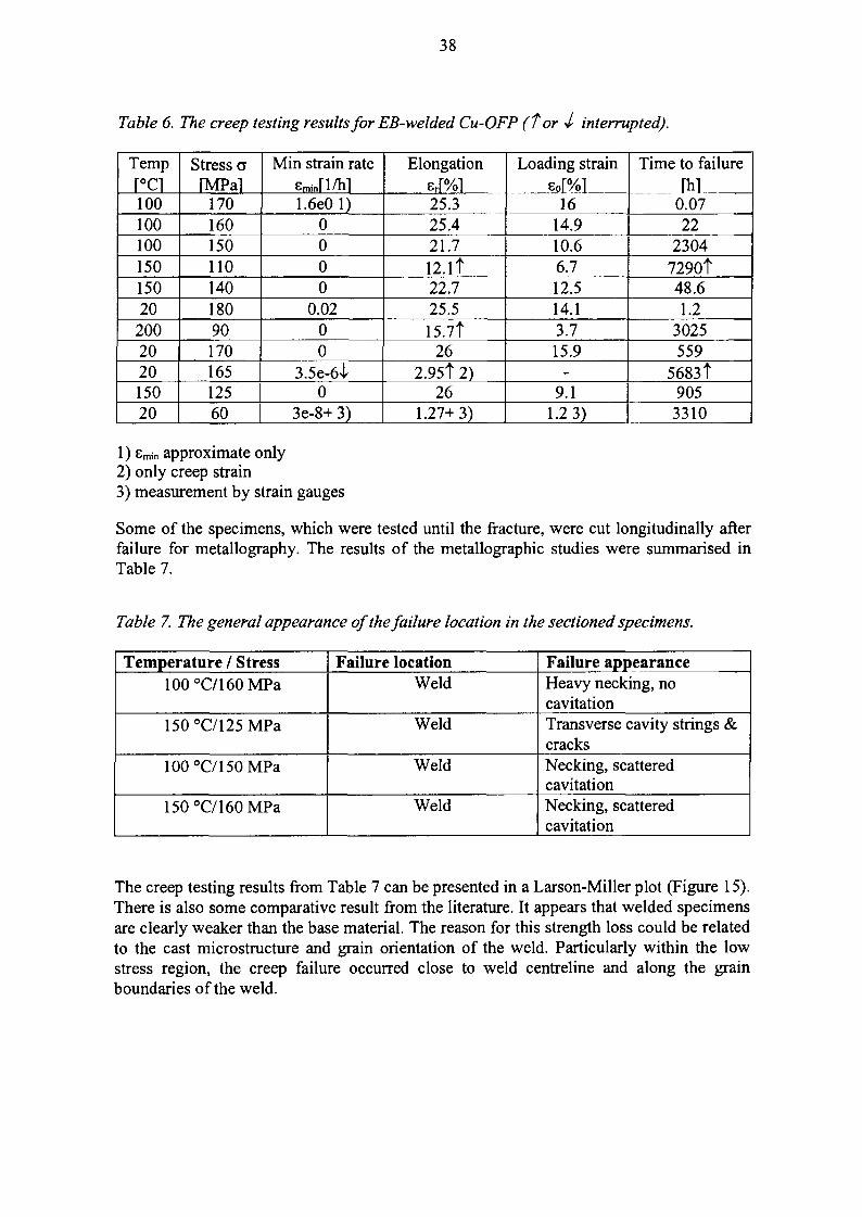
Table 6. The creep testing results for EB-welded Cu-OFP (Tor 4- interrupted).
Tempr°ci10010010015015020
200202015020
Stress aIMPal
1701601501101401809017016512560
Min strain rateEminri/hl1.6e0 1)
0000
0.0200
3.5e-6l0
3e-8+ 3)
Elongation
err%i25.325.421.712.lt22.725.515.7T
262.95T 2)
261.27+3)
Loading strainEoP/ol
1614.910.66.712.514.13.715.9
-9.1
1.2 3)
Time to failureThl
0.0722
23047290t48.61.2
3025559
5683t9053310
1) Emin approximate only2) only creep strain3) measurement by strain gauges
Some of the specimens, which were tested until the fracture, were cut longitudinally afterfailure for metallography. The results of the metallographic studies were summarised inTable 7.
Table 7. The general appearance of the failure location in the sectioned specimens.
Temperature / Stress100°C/160MPa
150°C/125MPa
100°C/150MPa
150°C/160MPa
Failure locationWeld
Weld
Weld
Weld
Failure appearanceHeavy necking, nocavitationTransverse cavity strings &cracksNecking, scatteredcavitationNecking, scatteredcavitation
The creep testing results from Table 7 can be presented in a Larson-Miller plot (Figure 15).There is also some comparative result from the literature. It appears that welded specimensare clearly weaker than the base material. The reason for this strength loss could be relatedto the cast microstructure and grain orientation of the weld. Particularly within the lowstress region, the creep failure occurred close to weld centreline and along the grainboundaries of the weld.
39
200
ISO
I
50
0
-Q „
-
-
3000
1
XXX
ooo
14000
1 1
0 ".
* \
\ «
*>
0
estimate from mtn. creep rateVTT test continuesStrain gauge test (com.)
I i
5000 6000
1
oooD O G
0
d , o OD
0
0 0 0
*
1
7000PLM-T'[log(t)+I]]
1 1
1M base material Cu-PVTT weld test to failure
-
0
oO 0
DO 0
* « O
\
\ op -
*. O3
1 1
8000 9000 IMO*
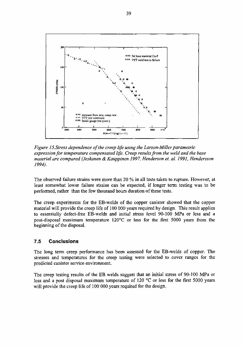
Figure 15. Stress dependence of the creep life using the Larson-Miller parametricexpression for temperature compensated life. Creep results from the weld and the basematerial are compared (Jeskanen & Kauppinen 1997, Henderson et. al. 1991, Hendersson1994).
The observed failure strains were more than 20 % in all tests taken to rupture. However, atleast somewhat lower failure strains can be expected, if longer term testing was to beperformed, rather than the few thousand hours duration of these tests.
The creep experiments for the EB-welds of the copper canister showed that the coppermaterial will provide the creep life of 100 000 years required by design. This result appliesto essentially defect-free EB-welds and initial stress level 90-100 MPa or less and apost-disposal maximum temperature 120°C or less for the first 5000 years from thebeginning of the disposal.
7.5 Conclusions
The long term creep performance has been assessed for the EB-welds of copper. Thestresses and temperatures for the creep testing were selected to cover ranges for thepredicted canister service environment.
The creep testing results of the EB welds suggest that an initial stress of 90-100 MPa orless and a post disposal maximum temperature of 120 °C or less for the first 5000 yearswill provide the creep life of 100 000 years required for the design.
40
8 SUMMARY AND CONCLUSIONS
The results obtained from the experiments on EBW for 50 mm thick copper are as follows.
(1) Considerably sound welds with 55-65 mm penetration depth, relatively free of internaldefects such as porosity were obtained using oxygen free copper (Cu-OF) and oxygen freephosphorus microalloyed copper (Cu-OFP). The quality of the weld was reasonably good,although some randomly occurred root defects still existed in the optimised weld. Thegeneral quality of the phosphorus deoxidised grade (Cu-DHP) was clearly lower than thequality of Cu-OF and Cu-OFP.
(2) The circular weld of 50 mm thick, 250 mm long and about 980 mm diametercylindrical shell was made using vertical and horizontal EB-welding. It has been shownthat it is technically possible to weld full scale canister lids using either vertical orhorizontal EB-welding.
(3) Vertical welding position proved to generate sounder welds than horizontal welding.This result applies both the main weld and slope out area.
(4) The welding results of the development program can be applied to full scale canistermanufacturing. The optimal welding parameters can be applied especially longitudinalbody welds of the canister manufacturing process which is based on hot rolling andbending.
(5) The slope out area of the vertical welding position was relatively sound. Thepenetration depth in the slope out from 50 mm up to 30 mm consisted of sparsely occurringroot defects. Otherwise the slope out area was defect free.
(6) Ultrasonic inspection technique for the quality verification of the copper canisterrequires specially developed probes for reliable inspection. Inspection using focusednormal incidence probes and focused angle beam probes are recommended. The mostcritical point, as far as the inspection is concerned, is the microstructure of the material.Further development work should concentrate on getting optimal microstructure within thematerial.
(7) The creep experiments for the EB-welds of the copper canister showed that the coppermaterial will provide the creep life of 100 000 years required by design. This result appliesto essentially defect-free EB-welds and initial stress level 90-100 MPa or less and apost-disposal maximum temperature 120°C or less for the first 5000 years from thebeginning of the disposal.
It was demonstrated that EBW could be applied to the production of nuclear waste canisteroverpack made of copper. According to the results, the vertical EB-technique is moreapplicable canister manufacturing and the lid closure technique than horisontalEB-technique. However, it is also possible to apply horizontal EB-welding for longitudinalbody welds of canister manufacturing.
41
9 REFERENCES
Aalto H., Rajainmaki, H & Laakso, L. 1996. Production methods and costs of oxygen freecopper canisters for nuclear waste disposal. Report POSIVA-96-08, Posiva Oy, Helsinki
ANSI/AWS C7.1-92. Recommended practices for electron beam welding. 1992. AnAmerican National Standard. American Welding Society, Miami, USA.
Auerkari, P., HolmstrSm, S. 1997. Long-term strength of EB welds of the canister fornuclear fuel disposal. Posiva Work Report-97-35e. Posiva Oy, Helsinki.
Dithey, U. Dobner M. 1995. Improved technology of radial electron beam welding oncylindrical components of large thickness steels. Report IIW Doc. No. IV-630-95,ISW-Welding Institute, Aachen University, Germany.
Hendersson, P.J., 1994. Creep of copper. International seminar on design and manufactureof copper canisters for nuclear waste. Sollentuna.
Hendersson, P.J., Osterberg, J.-O. & Ivarsson, B.G., 1991. Low temperature creep ofcopper intended for nuclear waste containers. IM-2780, Swedish Institute for MetalsResearch, Stockholm.
Jeskanen, H., Kauppinen, P. 1997. Ultrasonic inspection of electron beam welded joints incopper. Posiva Work Report-97-34e. Posiva Oy, Helsinki.
Leskov, G. I. 1989. Closure of annular joints in electron beam welding pipes with a wallthickness of up to 40 mm. Welding International 8/1989.
Raiko, H. Salo J-P. 1996. Design report of the canister for nuclear fuel disposal. ReportPosiva-96-13, Posiva Oy, Helsinki.
Tsukamoto, S., Irie, H. 1990. A study on electron beam welding phenomena. III. Meltingprocess and spiking phenomenon in electron beam welding. Quarterly Journal of the JapanWelding Society 8, (3), 37-42, August 1990.
Weiser, M., Fong, K. 1994. Application of the Taguchi method of experimental design toimproving ceramic processing. American Ceramic Society Bulletin Vol. 73, January 1994.
Wen, T-C, Lin, S-M. 1992. Aluminum colouring using robust design. Plating and SurfaceFinishing, October 1992.
42
Appendix 1: Horizontal beam welded lid
43
Appendix 2: Vertical beam welded lid
LIST OF REPORTS 1(3)
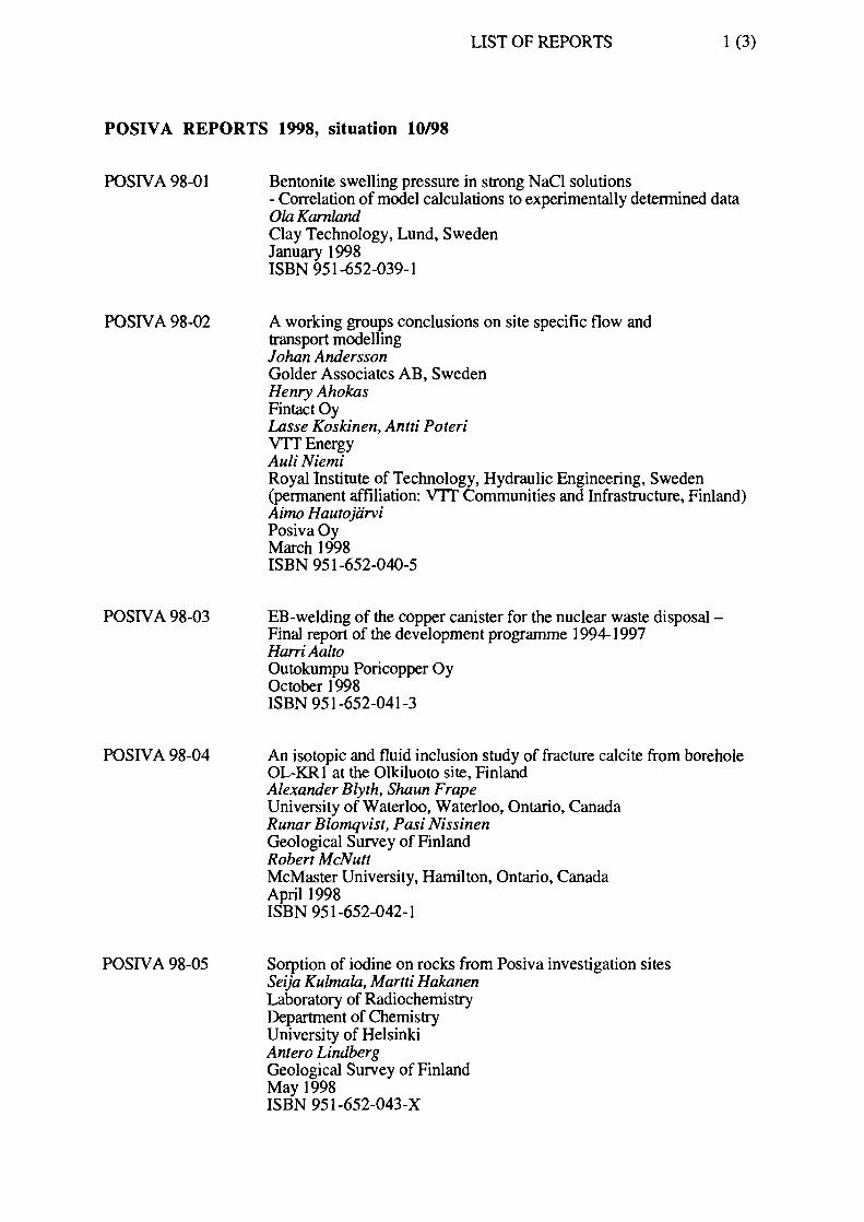
POSIVA REPORTS 1998, situation 10/98
POSIVA 98-01 Bentonite swelling pressure in strong NaCl solutions- Correlation of model calculations to experimentally determined dataOla KarnlandClay Technology, Lund, SwedenJanuary 1998ISBN 951-652-039-1
POSIVA 98-02 A working groups conclusions on site specific flow andtransport modellingJohan AnderssonGolder Associates AB, SwedenHenry AhokasFintact OyLasse Koskinen, Antti PoteriVTT EnergyAuli NiemiRoyal Institute of Technology, Hydraulic Engineering, Sweden(permanent affiliation: VTT Communities and Infrastructure, Finland)Aimo HautojarviPosiva OyMarch 1998ISBN 951-652-040-5
POSIVA 98-03 EB-welding of the copper canister for the nuclear waste disposal -Final report of the development programme 1994-1997HarriAaltoOutokumpu Poricopper OyOctober 1998ISBN 951-652-041-3
POSIVA 98-04 An isotopic and fluid inclusion study of fracture calcite from boreholeOL-KR1 at the Olkiluoto site, FinlandAlexander Blyth, Shaun FrapeUniversity of Waterloo, Waterloo, Ontario, CanadaRunar Blomqvist, Past NissinenGeological Survey of FinlandRobert McNuttMcMaster University, Hamilton, Ontario, CanadaApril 1998ISBN 951-652-042-1
POSIVA 98-05 Sorption of iodine on rocks from Posiva investigation sitesSeija Kulmala, Martti HakanenLaboratory of RadiochemistryDepartment of ChemistryUniversity of HelsinkiAntero LindbergGeological Survey of FinlandMay 1998ISBN951-652-043-X
LIST OF REPORTS 2(3)
POSIVA 98-06 Dissolution of unirradiated UO2 fuel in synthetic groundwater -Progress report '97Kaija OllilaVTT Chemical TechnologyJune 1998ISBN 951-652-044-8
POSIVA 98-07 Geochemical modelling of groundwater evolution and residence timeat the Kivetty sitePetteri Pitkdnen, Ari LuukkonenVTT Communities and InfrastructurePaula RuotsalainenFintact OyHilkka Leino-Forsman, Ulla VuorinenVTT Chemical TechnologyAugust 1998 (to be published)ISBN 951-652-045-6
POSIVA 98-08 Modelling gas migration in compacted bentonite- A report produced for the GAMBIT ClubP.J. Nash, B.T. Swift, M. Goodfield, W.R. RodwellAEA Technology pic, Dorchester, United KingdomAugust 1998ISBN 951-652-046-4
POSIVA 98-09 Geomicrobial investigations of groundwaters from Olkiluoto,Hastholmen, Kivetty and Romuvaara, FinlandShelley A. Haveman, Karsten PedersenGoteborg University, SwedenPaula RuotsalainenFintact OyAugust 1998ISBN 951-652-047-2
POSIVA 98-10 Geochemical modeling of groundwater evolution and residence timeat the Olkiluoto sitePetteri Pitkdnen, Ari LuukkonenVTT Communities and InfrastructureSeptember 1998 (to be published)ISBN 951-652-048-0
POSIVA 98-11 Sorption of cesium on Olkiluoto mica gneiss, granodiorite and graniteTuula Huitti, Martti HakanenLaboratory of Radiochemistry, Department of Chemistry,University of HelsinkiAntero LindbergGeological Survey of FinlandSeptemberISBN 951-652-049-9

LIST OF REPORTS 3(3)
POSIVA 98-12 Sorption of plutonium on rocks in groundwaters from Posivainvestigation sitesSeija Kulmala, Martti HakanenLaboratory of Radiochemistry, Department of Chemistry,University of HelsinkiAntero LindbergGeological Survey of FinlandSeptember 1998 (to be published)ISBN 951-652-050-2
POSIVA 98-13 Solubilities of uranium for TILA-99Kaija OllilaVTT Chemical TechnologyLasse AhonenGeological Survey of FinlandSeptember 1998 (to be published)ISBN 951-652-051-0
POSIVA 98-14 Solubility database for TILA-99Vila VuorinenVTT Chemical TechnologySeija Kulmala, Martti HakanenLaboratory of Radiochemistry, Department of Chemistry,University of HelsinkiLasse AhonenGeological Survey of FinlandTorbjorn CarlssonVTT Chemical TechnologySeptember 1998 (to be published)ISBN 951-652-052-9