Embed Size (px)
Citation preview
EB endlossion analyzer for TandemMirror ExperimentUpgradeJ. H. Foote, G. W. Coutts, L. R. Pedrotti, L. Schlander, and B. E. Wood Citation: Review of Scientific Instruments 56, 1117 (1985); doi: 10.1063/1.1138242 View online: http://dx.doi.org/10.1063/1.1138242 View Table of Contents: http://scitation.aip.org/content/aip/journal/rsi/56/5?ver=pdfcov Published by the AIP Publishing Articles you may be interested in The energy component analyzer and spectrum analysis of endloss ions in a tandem mirror Rev. Sci. Instrum. 62, 899 (1991); 10.1063/1.1142027 Operation of an E B endloss ion spectrometer on the Tara tandem mirror Rev. Sci. Instrum. 59, 1664 (1988); 10.1063/1.1140126 E parallel to B energy analyzer for measurement of endloss ions from the Mirror Fusion Test FacilityB Rev. Sci. Instrum. 56, 1114 (1985); 10.1063/1.1138241 TandemMirror ExperimentUpgrade neutral pressure measurement diagnostic systems Rev. Sci. Instrum. 56, 978 (1985); 10.1063/1.1138010 Measurement of sloshingion spatial profiles in end cell of tandem mirror experimentupgrade (TMXU) Phys. Fluids 26, 2335 (1983); 10.1063/1.864434
This article is copyrighted as indicated in the article. Reuse of AIP content is subject to the terms at: http://scitationnew.aip.org/termsconditions. Downloaded to IP:
128.118.88.48 On: Wed, 17 Dec 2014 18:38:37
Ell B end-loss-ion analyzer for Tandem-Mirror Experiment-Upgrade J. H. Foote, G. W. Coutts, l. R. Pedrotti, L. Schlander, and B. E. Wood
Lawrence Livermore National Laboratory, University of California, Livermore. California 94550
(Presented on 19 September 1984)
We are constructing and testing a diagnostic instrument to investigate, in detail, ions emanating along magnetic field lines from the plasma region of the TMX-U tandem-mirror experiment. This analyzer (of Tokamak Fusion Test Reactor design) contains parallel electric and magnetic fields, which yield ion mass and energy spatial separation, respectively. A two-dimensional array of 128 copper collector plates detects the particles. The entering ion flux is first well collimated and then focused onto the detector plane during the 180· bending in the magnetic field. This instrument is designed to measure higher particle energies than the present gridded end-loss analyzers as well as determine the energy spectra more accurately. Tandem-mirror plasma parameters to be investigated with this analyzer include end-plug potential, average central-cell-ion energy, and plasma potential in the thermal barrier and nearby regions. We plan a time resolution of up to 2 kHz for each detector.
INTRODUCTION
Tandem-Mirror Experiment-Upgrade (TMX-D) at Lawrence Livermore National Laboratory is an open-ended, controlled-fusion experiment using the tandem-mirror magnetic-field configuration with thermal barriers. 1-3 The openended feature means that ions and electrons can escape from the plasma region along magnetic field lines. Measurements of the escaping ions can provide information about the ions and their energies inside the plasma and about the space potentials existing in the plasma. This information is needed to understand the plasma formation and characteristics. At present, biased gridded detectors4 are used to provide some of these data.
The end-loss-ion spectrometer (ELISf discussed here is designed to measure higher particle energies than the present gridded end-loss analyzers (which have limited voltageholding capability) and to determine the energy spectra in more detail because particles of different masses and energies are separated spatially. More extensive measurements than before should be possible with the ELlS, and with faster time resolution. Also, electrons can be more easily separated from the ions.
I. APPARATUS
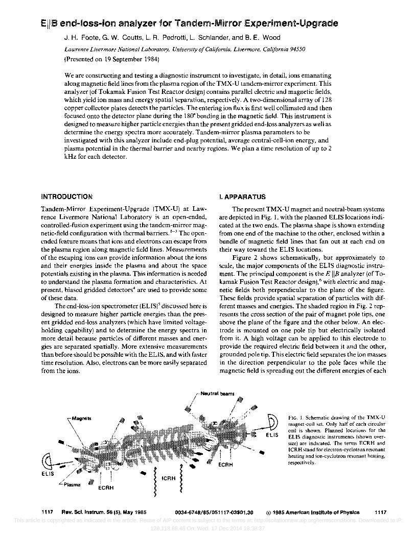
The present TMX-U magnet and neutral-beam systems are depicted in Fig. I, with the planned ELlS locations indicated at the two ends. The plasma shape is shown extending from one end of the machine to the other, enclosed within a bundle of magnetic field lines that fan out at each end on their way toward the ELlS locations.
Figure 2 shows schematically, but approximately to scale, the major components of the ELlS diagnostic instrument. The principal component is the E liB analyzer (of Tokamak Fusion Test Reactor design),6 with electric and magnetic fields both perpendicular to the plane of the figure. These fields provide spatial separation of particles with different masses and energies. The shaded region in Fig. 2 represents the cross section of the pair of magnet pole tips, one above the plane of the figure and the other below. An electrode is mounted on one pole tip but electrically isolated from it. A high voltage can be applied to this electrode to provide the required electric field between it and the other, grounded pole tip. This electric field separates the ion masses in the direction perpendicular to the pole faces while the magnetic field is spreading out the different energies of each
Neutral beams
EllS ! Plasma
; ECRH
1117 Rev. Scllnstrum. 56 (5), May 1985
III / /
f f ~ ~ ICRH I
0034-6748/85/051117-03$01.30
EllS
FIG. I. Schematic drawing of the TMX-U magnet-coil set. Only half of each circular coil is shown. Planned locations for the ELlS diagnostic instruments (shown oversize) are indicated. The terms ECRH and ICRH stand for electron-cyclotron resonant heating and ion-cyclotron resonant heating, respectively.
@ 1985 American Institute of Physics 1117
This article is copyrighted as indicated in the article. Reuse of AIP content is subject to the terms at: http://scitationnew.aip.org/termsconditions. Downloaded to IP:
128.118.88.48 On: Wed, 17 Dec 2014 18:38:37
so"" TOVIICUum
pump
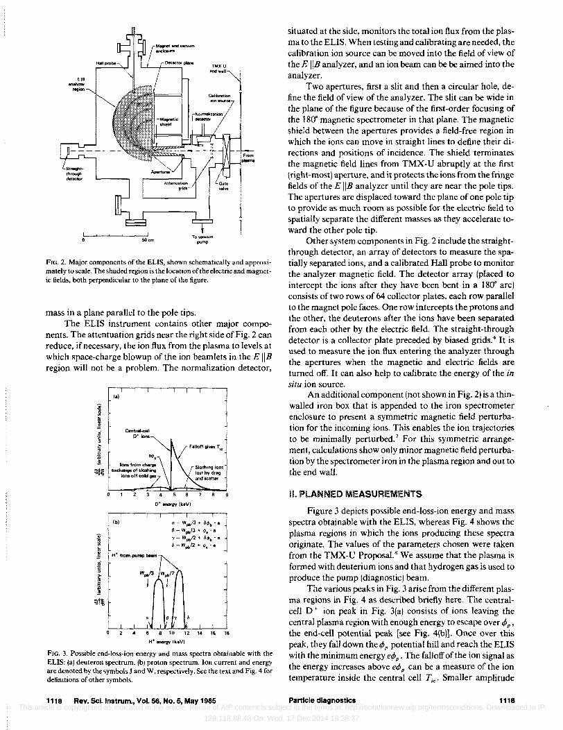
FIG. 2. Major components of the ELlS, shown schematically and approximately to scale. The shaded region is the location of the electric and magnetic fields, both perpendicular to the plane of the figure.
mass in a plane parallel to the pole tips. The ELlS instrument contains other major compo
nents. The attentuation grids near the right side of Fig. 2 can reduce, if necessary, the ion flux from the plasma to levels at which space-charge blowup of the ion beamlets in the E liB region will not be a problem. The normalization detector,
lal
I ~ .~' ~ ~
i :al~
Ibl
4 5
o+-vv IkeVI
" - Wpb/J + 6~b • e ~ - Wpb/J + ~ •.• l - Wpb/2 + 6" •.•
6 - Wpb12 + ~ •.•
9
4 6 8 10 12 14 16 18
H'....."., Ik.VI
FIG. 3. Possible end-loss-ion energy and mass spectra obtainable with the ELlS: (a) deuteron spectrum, (b) proton spectrum. Ion current and energy are denoted by the symbols J and W, respectively. See the text and Fig. 4 for definitions of other symbols.
1118 Rev. ScI_lnstrum., Vol. 56, No.5, May 1985
situated at the side, monitors the total ion flux from the plasma to the ELlS. When testing and calibrating are needed, the calibration ion source can be moved into the field of view of the E liB analyzer, and an ion beam can be be aimed into the analyzer.
Two apertures, first a slit and then a circular hole, define the field of view of the analyzer. The slit can be wide in the plane of the figure because of the first-order focusing of the 180· magnetic spectrometer in that plane. The magnetic shield between the apertures provides a field-free region in which the ions can move in straight lines to define their directions and positions of incidence. The shield terminates the magnetic field lines from TMX-U abruptly at the first (right-most) aperture, and it protects the ions from the fringe fields of the E liB analyzer until they are near the pole tips. The apertures are displaced toward the plane of one pole tip to provide as much room as possible for the electric field to spatially separate the different masses as they accelerate toward the other pole tip.
Other system components in Fig. 2 include the straightthrough detector, an array of detectors to measure the spatially separated ions, and a calibrated Hall probe to monitor the analyzer magnetic field. The detector array (placed to intercept the ions after they have been bent in a 180· arc) consists of two rows of 64 collector plates, each row parallel to the magnet pole faces. One row intercepts the protons and the other, the deuterons after the ions have been separated from each other by the electric field. The straight-through detector is a collector plate preceded by biased grids.4 It is used to measure the ion flux entering the analyzer through the apertures when the magnetic and electric fields are turned off. It can also help to calibrate the energy of the in situ ion source.
An additional component (not shown in Fig. 2) is a thinwalled iron box that is appended to the iron spectrometer enclosure to present a symmetric magnetic field perturbation for the incoming ions. This enables the ion trajectories to be minimally perturbed. 7 For this symmetric arrangement, calculations show only minor magnetic field perturbation by the spectrometer iron in the plasma region and out to the end wall.
Ii. PLANNED MEASUREMENTS
Figure 3 depicts possible end-loss-ion energy and mass spectra obtainable with the EUS, whereas Fig. 4 shows the plasma regions in which the ions producing these spectra originate. The values of the parameters chosen were taken from the TMX-U Proposal.H We assume that the plasma is formed with deuterium ions and that hydrogen gas is used to produce the pump (diagnostic) beam.
The various peaks in Fig. 3 arise from the different plasma regions in Fig. 4 as described briefly here. The centralcell D + ion peak in Fig. 3(a) consists of ions l.eaving the central plasma region with enough energy to escape over tPP '
the end-cell potential peak [see Fig. 4(b)l. Once over this peak, they fall down the tPp potential hill and reach the ELlS with the minimum energy etPp. The falloff of the ion signal as the energy increases above etPp can be a measure of the ion temperature inside the central cell Tic' Smaller amplitude
Particle diagnostics 1118 This article is copyrighted as indicated in the article. Reuse of AIP content is subject to the terms at: http://scitationnew.aip.org/termsconditions. Downloaded to IP:
128.118.88.48 On: Wed, 17 Dec 2014 18:38:37
(a) East end Central·cell
midplane
-5 -4 -3 -2 -1 a 2 3
Axial distance. z (m)
D+ signals can be obtained from the trapped sloshing ions in the end cell, either from charge exchange off the cold background gas or from sloshing ions escaping from the end cell after losing energy there and scattering into the loss cone.
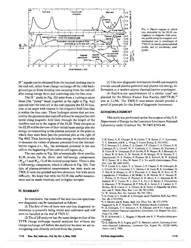
The H+ peaks in Fig. 3(b) arise from a hydrogen-atom beam [the "pump" beam depicted at the right in Fig. 4(a)] injected into the end cell at the end opposite the ELlS location, at an angle with respect to the magnetic field lines that is within the loss cone. Those hydrogen atoms that are ionized by the plasma in that end cell will not be trapped but will spiral along magnetic field lines through the length of the machine and on to the region of the ELlS. Their energies at the ELlS will be the sum of their initial beam energy plus the energy corresponding to the plasma potential at the point at which they were born [see the potential plot at the right of Fig. 4(b)]. Thus, knowing the beam energy, we should be able to measure the values of plasma potential from the thermalbarrier region (i.e., OifJb' the minimum potential in the end cell) to the beginning of the central-ceU region (ifJe).
The two peaks in Fig. 3(b) schematically show possible ELlS results for the third- and half-energy components (WPb /3 and Wpb /2) of the neutral pump beam. There is also a full-energy component, which is offscale in Fig. 3(b). This type of plasma-potential measurement has been made on TMX-U with the gridded end-loss detectors, but with much difficulty. We hope that with the ELlS this useful measurement can be made routinely and to higher energies.
In. SUMMARY
In conclusion, the status of the end-Ioss-ion-spectrometer diagnostic can be summarized as follows.
(1) The first of two of these new end-loss diagnostic instruments is presently being tested and calibrated and will soon be installed at the end ofTMX-U.
(2) The E liB analyzer has the same design as that of the TFfR charge exchange neutral analyzer but without the charge exchange cell before the analyzer because we are investigating ions directly emitted from the plasma.
1119 Rev. Sci.lnstrum., Vol. 56, No.5, May 1985
West end 2.5 E co
2.0 "D-o;
1.5 ;;:::
" .g 1.0 " '" '" 0.5 ::;;
FIG. 4. Plasma regions in which :;- ions detectable by the ELlS can ~ originate; (a) magnetic field inten-<3-
OJ sity profile along the magnetic and 2.0 'g mechanical axis (z coordinate) of 1.0 $ TMX-U, (b) plasma-potential axial 0
0 c.. profile, and (c) ion-density axial
- 2.5 profile. - 2.0 M
'" 1.5 - E ~"
1.0 'ViM ,,~
",0
0.5 c~
a 4 5 6 7 8
(3) This new diagnostic instrument should conveniently provide crucial plasma-potential and plasma-ion-energy information in a tandem-mirror thermal-barrier experiment.
(4) End-loss-ion spectrometers of a similar type9 are planned for the Mirror Fusion Test Facility (MFfF-B),1O also at LLNL. The TMX-U instrument should provide a proof of principle for this kind of diagnostic instrument.
ACKNOWLEDGMENT
This work was performed under the auspices of the U.S. Department of Energy by the Lawrence Livermore National Laboratory under Contract No. W-7405-ENG-48.
'J. H. Foote, A. K. Chargin, R. H. Cohen, T. B. Kaiser, C. V. Karmendy, T. C. Simonen. and R. L Wong, J. Fusion Energy 2, 383 (1982).
2T. C. Simonen, S. L. Allen, T. A. Casper, 1. F. Clauser, C. A. Clower, F. H. Coensgen, D. L. Correll, W. F. Cummins, C. C. Damm, M. Flammer, 1. H. Foote, R. K. Goodman. D. P. Grubb. E. B. Hooper, R. S. Hornady, A. L. Hunt, R. G. Kerr, A. W. Molvik, R. H. Munger, W. E. Nellsen, T. 1. Orzechowski, w. L. Pickles, P. Poulsen, M. E. Rensink, B. W. Stallard, w. C. Turner. W. L. Hsu, W. Bauer, T. L. Yu, and D. Zimmermann, Phys. Rev. Lett. 50, 1668 (1983).
3D. P. Grubb. S. L. Allen, T. A. Casper, 1. F. Clauser, F. H. Coensgen, D. L. Correll, W. F. Cummins, C. C. Damm, J. H. Foote, R. K. Goodman. D. N. Hill, E. B. Hooper, Jr .• R. S. Hornady, A. L. Hunt, R. G. Kerr, G. W. Leppelmeier. 1. Marilleau, J. M. Moller, A. w. Molvik. W. E. Nexsen. W. L. Pickles, G. D. Porter, P. Poulsen, E. H. Silver, T. C. Simonen, B. W. Stallard, W. C. Turner, W. L Hsu. T. L. Yu, 1. D. Barter, T. Christensen, G. Dimonte, T. W. Romesser, R. F. Ellis, R. A. lames, C. l. Lasnier, L. V. Berzins, M. R. Carter, C. A. Clower. B. H. Failor, S. Falabella, M. Flammer, and T. Nash, Phys. Rev. Lett. 53, 783 (1984).
4A. w. Molvik. Rev. Sci. Instrum. 52,704 (1981). '1. H. Foote, D. P. Grubb, R. S. Hornady, and S. Falabella, Bull. Am. Phys. Soc. 28, 1119 (1983).
·S. S. Medley and R. Kaita, Bull. Am. Phys. Soc. 24,93311979). 1Suggested by R. F. Wuerker, TRW, Redondo Beach. California. "F. H. Coensgen, T. C. Simonen, A. K. Chargin, and B. G. Logan, Lawrence Livermore National Laboratory, Livermore, CA. Report No. LLLProp-I72, 1980.
9R. K. Kirkwood, L. L. Higgins, J. Munch, and R. F. Wuerker (these proceedings).
IOD. E. Baldwin, B. G. Logan, and T. C. Simonen, editors, Lawrence livermore National Laboratory, Livermore CA, Report No. UCID-18496. Parts I and 2, 1980.
Particle diagnostiCS 1119
This article is copyrighted as indicated in the article. Reuse of AIP content is subject to the terms at: http://scitationnew.aip.org/termsconditions. Downloaded to IP:
128.118.88.48 On: Wed, 17 Dec 2014 18:38:37