Embed Size (px)
Citation preview
040301
2000 APC Incorporated, Signal Hill, CA 90806 USA (562) 424-1100
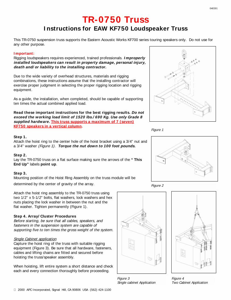
Figure 2
Figure 4 Two Cabinet Application
Figure 3 Single cabinet Application
TR-0750 Truss Instructions for EAW KF750 Loudspeaker Truss
This TR-0750 suspension truss supports the Eastern Acoustic Works KF700 series touring speakers only. Do not use for any other purpose. Important: Rigging loudspeakers requires experienced, trained professionals. Improperly installed loudspeakers can result in property damage, personal injury, death and/or liability to the installing contractor. Due to the wide variety of overhead structures, materials and rigging combinations, these instructions assume that the installing contractor will exercise proper judgment in selecting the proper rigging location and rigging equipment. As a guide, the installation, when completed, should be capable of supporting ten times the actual combined applied load. Read these important instructions for the best rigging results. Do not exceed the working load limit of 1520 lbs./690 Kg. Use only Grade 8 supplied hardware. This truss supports a maximum of 7 (seven) KF750 speakers in a vertical column.
Step 1. Attach the hoist ring to the center hole of the hoist bracket using a 3/4” nut and a 3/4” washer (Figure 1). Torque the nut down to 100 foot pounds. Step 2. Lay the TR-0750 truss on a flat surface making sure the arrows of the “ This End Up” labels point up. Step 3. Mounting position of the Hoist Ring Assembly on the truss module will be
determined by the center of gravity of the array. Attach the hoist ring assembly to the TR-0750 truss using two 1/2” x 5-1/2” bolts, flat washers, lock washers and hex nuts placing the lock washer in between the nut and the flat washer. Tighten permanently (Figure 1). Step 4. Array/Cluster Procedures Before starting, be sure that all cables, speakers, and fasteners in the suspension system are capable of supporting five to ten times the gross weight of the system. Single Cabinet application Capture the hoist ring of the truss with suitable rigging equipment (Figure 3). Be sure that all hardware, fasteners, cables and lifting chains are fitted and secured before hoisting the truss/speaker assembly. When hoisting, lift entire system a short distance and check each and every connection thoroughly before proceeding.
Figure 1
040301
2000 APC Incorporated, Signal Hill, CA 90806 U
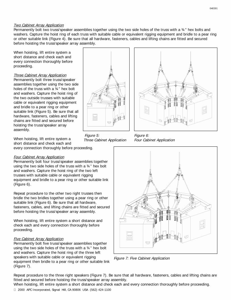
nFigure 6: Four Cabinet Application
Two Cabinet Array Application Permanently bolt two truss/speaker assemblies together using the two side holes of the truss with a ¾” hex bolts and washers. Capture the hoist ring of each truss with suitable cable or equivalent rigging equipment and bridle to a pear ring or other suitable link (Figure 4). Be sure that all hardware, fasteners, cables and lifting chains are fitted and secured before hoisting the truss/speaker array assembly. When hoisting, lift entire system a short distance and check each and every connection thoroughly before proceeding. Three Cabinet Array Application Permanently bolt three truss/speaker assemblies together using the two side holes of the truss with a ¾” hex bolt and washers. Capture the hoist ring of the two outside trusses with suitable cable or equivalent rigging equipment and bridle to a pear ring or other suitable link (Figure 5). Be sure that all hardware, fasteners, cables and lifting chains are fitted and secured before hoisting the truss/speaker array assembly. When hoisting, lift entire system a short distance and check each and every connection thoroughly before procee Four Cabinet Array Application Permanently bolt four truss/speaker assemusing the two side holes of the truss with and washers. Capture the hoist ring of thetrusses with suitable cable or equivalent riequipment and bridle to a pear ring or oth(Figure 6). Repeat procedure to the other two right trbridle the two bridles together using a peasuitable link (Figure 6). Be sure that all hafasteners, cables, and lifting chains are fittbefore hoisting the truss/speaker array as When hoisting, lift entire system a short dcheck each and every connection thoroughproceeding. Five Cabinet Array Application Permanently bolt five truss/speaker assemusing the two side holes of the truss with and washers. Capture the hoist ring of thespeakers with suitable cable or equivalentequipment then bridle to a pear ring or ot(Figure 7). Repeat procedure to the three right speakfitted and secured before hoisting the trusWhen hoisting, lift entire system a short d
Figure 5: Three Cabinet Applicatio
SA (562) 424-1100
Figure 7: Five Cabinet Application
ding.
blies together a ¾” hex bolt two left gging er suitable link
usses then r ring or other rdware, ed and secured sembly.
istance and ly before
blies together a ¾” hex bolt three left rigging her suitable link
ers (Figure 7). Be sure that all hardware, fasteners, cables and lifting chains are s/speaker array assembly. istance and check each and every connection thoroughly before proceeding.
040301
2000 APC Incorporated, Signal Hill, CA 90806 USA (562) 424-1100
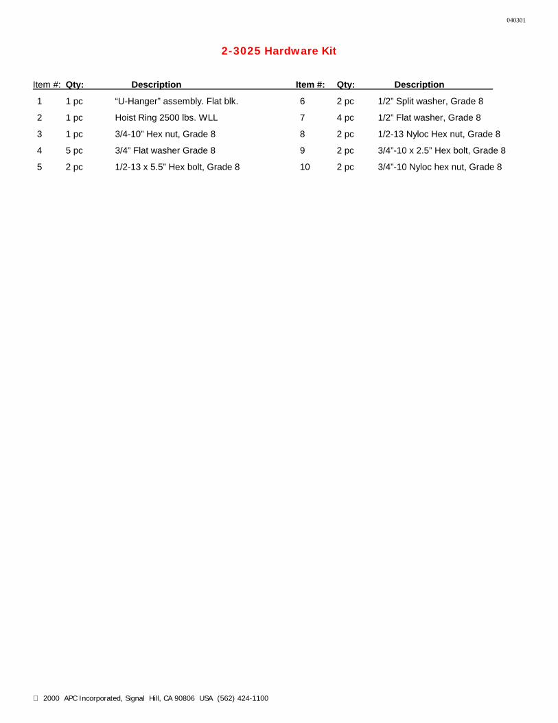
2-3025 Hardware Kit
Item #: Qty: Description Item #: Qty: Description
1 1 pc “U-Hanger” assembly. Flat blk. 6 2 pc 1/2” Split washer, Grade 8
2 1 pc Hoist Ring 2500 lbs. WLL 7 4 pc 1/2” Flat washer, Grade 8
3 1 pc 3/4-10” Hex nut, Grade 8 8 2 pc 1/2-13 Nyloc Hex nut, Grade 8
4 5 pc 3/4” Flat washer Grade 8 9 2 pc 3/4”-10 x 2.5” Hex bolt, Grade 8
5 2 pc 1/2-13 x 5.5” Hex bolt, Grade 8 10 2 pc 3/4”-10 Nyloc hex nut, Grade 8
2001 APC Incorporated, Signal Hill, CA 90806 USA (562) 424-1100
TR-0750-LT Truss Bar Instructions for EAW KF750 Loudspeaker Truss
Eyebolt Suspension
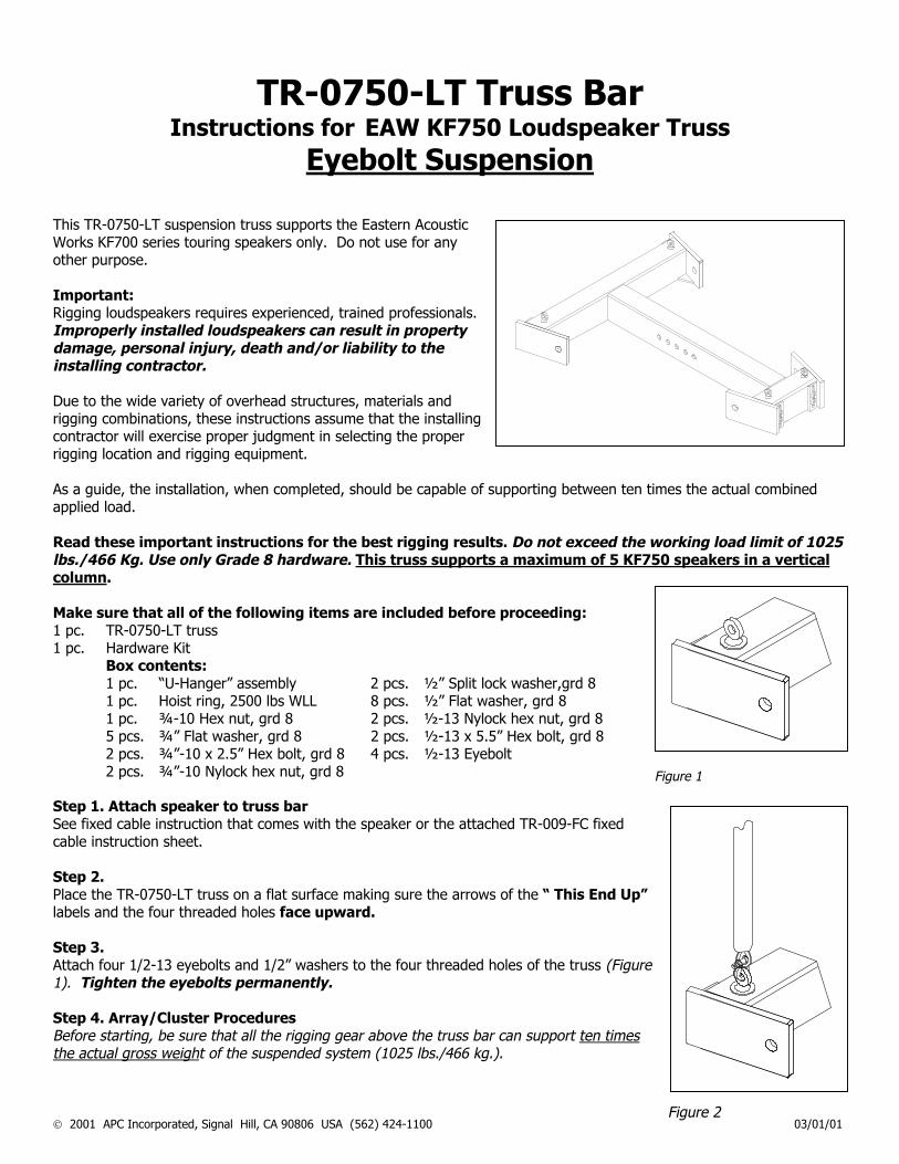
This TR-0750-LT suspension truss supports the Eastern Acoustic Works KF700 series touring speakers only. Do not use for any other purpose. Important: Rigging loudspeakers requires experienced, trained professionals. Improperly installed loudspeakers can result in property damage, personal injury, death and/or liability to the installing contractor. Due to the wide variety of overhead structures, materials and rigging combinations, these instructions assume that the installing contractor will exercise proper judgment in selecting the proper rigging location and rigging equipment. As a guide, the installation, when completed, should be capable of suapplied load. Read these important instructions for the best rigging resultslbs./466 Kg. Use only Grade 8 hardware. This truss supports column. Make sure that all of the following items are included before 1 pc. TR-0750-LT truss 1 pc. Hardware Kit Box contents: 1 pc. “U-Hanger” assembly 2 pcs. ½” Split loc 1 pc. Hoist ring, 2500 lbs WLL 8 pcs. ½” Flat was 1 pc. ¾-10 Hex nut, grd 8 2 pcs. ½-13 Nyloc 5 pcs. ¾” Flat washer, grd 8 2 pcs. ½-13 x 5.5” 2 pcs. ¾”-10 x 2.5” Hex bolt, grd 8 4 pcs. ½-13 Eyebo 2 pcs. ¾”-10 Nylock hex nut, grd 8 Step 1. Attach speaker to truss bar See fixed cable instruction that comes with the speaker or the attachcable instruction sheet. Step 2. Place the TR-0750-LT truss on a flat surface making sure the arrows labels and the four threaded holes face upward. Step 3. Attach four 1/2-13 eyebolts and 1/2” washers to the four threaded ho1). Tighten the eyebolts permanently. Step 4. Array/Cluster Procedures Before starting, be sure that all the rigging gear above the truss bar the actual gross weight of the suspended system (1025 lbs./466 kg.)
Figure 1
F
pporting between ten times the actual combined
. Do not exceed the working load limit of 1025 a maximum of 5 KF750 speakers in a vertical
proceeding:
k washer,grd 8 her, grd 8 k hex nut, grd 8 Hex bolt, grd 8 lt
ed TR-009-FC fixed
of the “ This End Up”
les of the truss (Figure
can support ten times .
03/01/01
igure 2
2
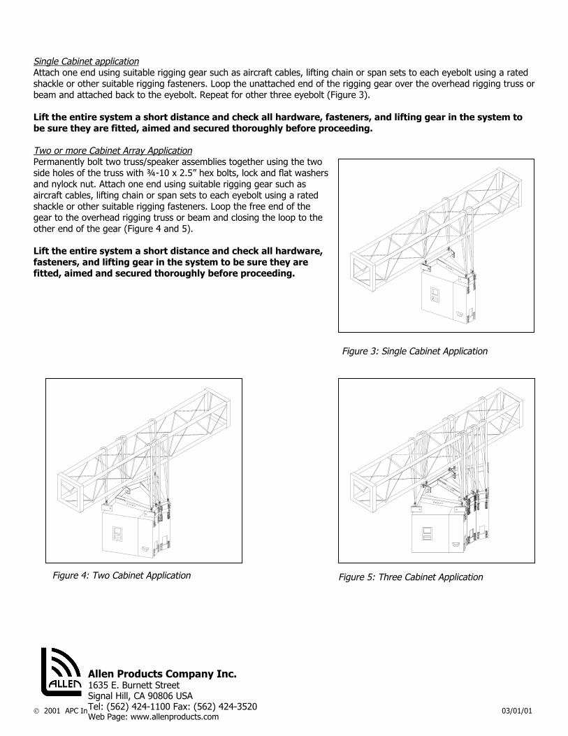
Figure 3: Single Cabinet Application
Single Cabinet application Attach one end using suitable rigging gear such as aircraft cables, lifting chain or span sets to each eyebolt using a rated shackle or other suitable rigging fasteners. Loop the unattached end of the rigging gear over the overhead rigging truss or beam and attached back to the eyebolt. Repeat for other three eyebolt (Figure 3). Lift the entire system a short distance and check all hardware, fasteners, and lifting gear in the system to be sure they are fitted, aimed and secured thoroughly before proceeding. Two or more Cabinet Array Application Permanently bolt two truss/speaker assemblies together using the two side holes of the truss with ¾-10 x 2.5” hex bolts, lock and flat washers and nylock nut. Attach one end using suitable rigging gear such as aircraft cables, lifting chain or span sets to each eyebolt using a rated shackle or other suitable rigging fasteners. Loop the free end of the gear to the overhead rigging truss or beam and closing the loop to the other end of the gear (Figure 4 and 5). Lift the entire system a short distance and check all hardware, fasteners, and lifting gear in the system to be sure they are fitted, aimed and secured thoroughly before proceeding.
001 APC Incorporated, Signal Hill, CA 90806 USA (562) 424-1100 03/01/01
Figure 5: Three Cabinet Application
Allen Products Company Inc. 1635 E. Burnett Street Signal Hill, CA 90806 USA Tel: (562) 424-1100 Fax: (562) 424-3520 Web Page: www.allenproducts.com
Figure 4: Two Cabinet Application