Embed Size (px)
Citation preview
Powerware Series
Eaton 9355 UPS
10/15 kVA
User's Guide
®

Class A EMC StatementsFCC Part 15
NOTE This equipment has been tested and found to comply with the limits for a Class A digital device, pursuant topart 15 of the FCC Rules. These limits are designed to provide reasonable protection against harmful interferencewhen the equipment is operated in a commercial environment. This equipment generates, uses, and can radiateradio frequency energy and, if not installed and used in accordance with the instruction manual, may cause harmfulinterference to radio communications. Operation of this equipment in a residential area is likely to cause harmfulinterference in which case the user will be required to correct the interference at his own expense.
ICES-003
This Class A Interference Causing Equipment meets all requirements of the Canadian Interference CausingEquipment Regulations ICES‐003.
Cet appareil numérique de la classe A respecte toutes les exigences du Reglement sur le matériel brouilleur duCanada.
IEC 62040-2
Some configurations are classified under IEC 62040-2 as “C2 UPS for Unrestricted Sales Distribution.”
Eaton, Powerware, ABM, Powerware Hot Sync, and X-Slot are registered trademarks and ConnectUPS is atrademark of Eaton or its subsidiaries and affiliates. Greenlee is a registered trademark of Greenlee Textron.Modbus is a registered trademark of Schneider Automation. National Electrical Code and NEC are registeredtrademarks of National Fire Protection Association, Inc. All other trademarks are property of their respectivecompanies.
�Copyright 2005–2015 Eaton, Raleigh, NC, USA. All rights reserved. No part of this document may be reproducedin any way without the express written approval of Eaton.

Special SymbolsThe following are examples of symbols used on the UPS or accessories to alert you to importantinformation:
RISK OF ELECTRIC SHOCK - Observe the warning associated with the risk of electricshock symbol.
CAUTION: REFER TO OPERATOR'S MANUAL - Refer to your operator's manual foradditional information, such as important operating and maintenanceinstructions.
This symbol indicates that you should not discard the UPS or the UPS batteriesin the trash. This product contains sealed, lead‐acid batteries and must bedisposed of properly. For more information, contact your local recycling/reuse orhazardous waste center.
This symbol indicates that you should not discard waste electrical or electronicequipment (WEEE) in the trash. For proper disposal, contact your localrecycling/reuse or hazardous waste center.
ON - Indicates that the switch is in the ON position.
OFF - Indicates that the switch is in the OFF position.
PHASE - The word “phase.”

Eaton 9355 UPS (10/15 kVA) User's Guide � 164201594 Rev F www.eaton.com/powerquality i
Table of Contents
1 Introduction 1. . . . . . . . . . . . . . . . . . . . . . . . . . . . . . . . . . . . . . . . . . . . . . . . . . . . . . . . .
2 Safety Warnings 5. . . . . . . . . . . . . . . . . . . . . . . . . . . . . . . . . . . . . . . . . . . . . . . . . . . . .
3 UPS Setup 9. . . . . . . . . . . . . . . . . . . . . . . . . . . . . . . . . . . . . . . . . . . . . . . . . . . . . . . . . .Inspecting the Equipment 9. . . . . . . . . . . . . . . . . . . . . . . . . . . . . . . . . . . . . . . . . . . . . . . . . . . . . . . . . . . . . . .Floor Loading 10. . . . . . . . . . . . . . . . . . . . . . . . . . . . . . . . . . . . . . . . . . . . . . . . . . . . . . . . . . . . . . . . . . . . . . .Clearances 10. . . . . . . . . . . . . . . . . . . . . . . . . . . . . . . . . . . . . . . . . . . . . . . . . . . . . . . . . . . . . . . . . . . . . . . . .Unloading the Cabinet(s) 11. . . . . . . . . . . . . . . . . . . . . . . . . . . . . . . . . . . . . . . . . . . . . . . . . . . . . . . . . . . . . . .
Three-High Cabinets or Two-High EBMs 11. . . . . . . . . . . . . . . . . . . . . . . . . . . . . . . . . . . . . . . . . . . . . . . . . .Two-High UPS Cabinets 15. . . . . . . . . . . . . . . . . . . . . . . . . . . . . . . . . . . . . . . . . . . . . . . . . . . . . . . . . . . . .
Selecting an Installation Option 18. . . . . . . . . . . . . . . . . . . . . . . . . . . . . . . . . . . . . . . . . . . . . . . . . . . . . . . . . .
4 UPS Installation 19. . . . . . . . . . . . . . . . . . . . . . . . . . . . . . . . . . . . . . . . . . . . . . . . . . . . . .
5 Version 1 Wall-Mounted Bypass Switch Installation 29. . . . . . . . . . . . . . . . . . . . . . . . .
6 Version 2 Wall-Mounted Bypass Switch Installation 41. . . . . . . . . . . . . . . . . . . . . . . . .
7 Stabilizing the Cabinet 55. . . . . . . . . . . . . . . . . . . . . . . . . . . . . . . . . . . . . . . . . . . . . . . .
8 Extended Battery Module Installation 59. . . . . . . . . . . . . . . . . . . . . . . . . . . . . . . . . . . .
9 Communication 63. . . . . . . . . . . . . . . . . . . . . . . . . . . . . . . . . . . . . . . . . . . . . . . . . . . . . .Installing Communication Options and Control Terminals 64. . . . . . . . . . . . . . . . . . . . . . . . . . . . . . . . . . . . . . . . .Communication Options 67. . . . . . . . . . . . . . . . . . . . . . . . . . . . . . . . . . . . . . . . . . . . . . . . . . . . . . . . . . . . . . . .
DB-9 Communication Port 67. . . . . . . . . . . . . . . . . . . . . . . . . . . . . . . . . . . . . . . . . . . . . . . . . . . . . . . . . . . .X-Slot Cards 68. . . . . . . . . . . . . . . . . . . . . . . . . . . . . . . . . . . . . . . . . . . . . . . . . . . . . . . . . . . . . . . . . . . . .Remote Monitor Panel 70. . . . . . . . . . . . . . . . . . . . . . . . . . . . . . . . . . . . . . . . . . . . . . . . . . . . . . . . . . . . . .Industrial Relay Card 74. . . . . . . . . . . . . . . . . . . . . . . . . . . . . . . . . . . . . . . . . . . . . . . . . . . . . . . . . . . . . . .Power Management Software 75. . . . . . . . . . . . . . . . . . . . . . . . . . . . . . . . . . . . . . . . . . . . . . . . . . . . . . . . .
Control Terminals 76. . . . . . . . . . . . . . . . . . . . . . . . . . . . . . . . . . . . . . . . . . . . . . . . . . . . . . . . . . . . . . . . . . . .Remote Emergency Power-off 77. . . . . . . . . . . . . . . . . . . . . . . . . . . . . . . . . . . . . . . . . . . . . . . . . . . . . . . . .Relay Output Contacts 78. . . . . . . . . . . . . . . . . . . . . . . . . . . . . . . . . . . . . . . . . . . . . . . . . . . . . . . . . . . . . .Programmable Signal Inputs 78. . . . . . . . . . . . . . . . . . . . . . . . . . . . . . . . . . . . . . . . . . . . . . . . . . . . . . . . . .
TABLE OF CONTENTS
Eaton 9355 UPS (10/15 kVA) User's Guide � 164201594 Rev F www.eaton.com/powerqualityii
10 Operation 81. . . . . . . . . . . . . . . . . . . . . . . . . . . . . . . . . . . . . . . . . . . . . . . . . . . . . . . . . . .Control Panel Functions 81. . . . . . . . . . . . . . . . . . . . . . . . . . . . . . . . . . . . . . . . . . . . . . . . . . . . . . . . . . . . . . . .
Changing the Language 82. . . . . . . . . . . . . . . . . . . . . . . . . . . . . . . . . . . . . . . . . . . . . . . . . . . . . . . . . . . . .Display Functions 82. . . . . . . . . . . . . . . . . . . . . . . . . . . . . . . . . . . . . . . . . . . . . . . . . . . . . . . . . . . . . . . . . .User Settings 84. . . . . . . . . . . . . . . . . . . . . . . . . . . . . . . . . . . . . . . . . . . . . . . . . . . . . . . . . . . . . . . . . . . . .
Initial Startup 86. . . . . . . . . . . . . . . . . . . . . . . . . . . . . . . . . . . . . . . . . . . . . . . . . . . . . . . . . . . . . . . . . . . . . . .UPS Startup 86. . . . . . . . . . . . . . . . . . . . . . . . . . . . . . . . . . . . . . . . . . . . . . . . . . . . . . . . . . . . . . . . . . . . . . . .
Normal Mode Startup 87. . . . . . . . . . . . . . . . . . . . . . . . . . . . . . . . . . . . . . . . . . . . . . . . . . . . . . . . . . . . . . .Starting the UPS on Battery 88. . . . . . . . . . . . . . . . . . . . . . . . . . . . . . . . . . . . . . . . . . . . . . . . . . . . . . . . . . .Internal Bypass Startup 89. . . . . . . . . . . . . . . . . . . . . . . . . . . . . . . . . . . . . . . . . . . . . . . . . . . . . . . . . . . . . .UPS Maintenance Bypass Startup 90. . . . . . . . . . . . . . . . . . . . . . . . . . . . . . . . . . . . . . . . . . . . . . . . . . . . . .Wall-Mounted Maintenance Bypass Startup 90. . . . . . . . . . . . . . . . . . . . . . . . . . . . . . . . . . . . . . . . . . . . . . .
Configuring the UPS for EBMs 91. . . . . . . . . . . . . . . . . . . . . . . . . . . . . . . . . . . . . . . . . . . . . . . . . . . . . . . . . . .UPS Shutdown 92. . . . . . . . . . . . . . . . . . . . . . . . . . . . . . . . . . . . . . . . . . . . . . . . . . . . . . . . . . . . . . . . . . . . . .
11 UPS Maintenance 93. . . . . . . . . . . . . . . . . . . . . . . . . . . . . . . . . . . . . . . . . . . . . . . . . . . .UPS and Battery Care 93. . . . . . . . . . . . . . . . . . . . . . . . . . . . . . . . . . . . . . . . . . . . . . . . . . . . . . . . . . . . . . . . . .
Storing the UPS and Batteries 93. . . . . . . . . . . . . . . . . . . . . . . . . . . . . . . . . . . . . . . . . . . . . . . . . . . . . . . . .When to Replace Batteries 94. . . . . . . . . . . . . . . . . . . . . . . . . . . . . . . . . . . . . . . . . . . . . . . . . . . . . . . . . . . . . .Recycling the Used Battery or UPS 94. . . . . . . . . . . . . . . . . . . . . . . . . . . . . . . . . . . . . . . . . . . . . . . . . . . . . . . .Using the UPS Maintenance Bypass Switch 95. . . . . . . . . . . . . . . . . . . . . . . . . . . . . . . . . . . . . . . . . . . . . . . . . .Using the Wall-Mounted Bypass Cabinet 97. . . . . . . . . . . . . . . . . . . . . . . . . . . . . . . . . . . . . . . . . . . . . . . . . . . .
12 Specifications 99. . . . . . . . . . . . . . . . . . . . . . . . . . . . . . . . . . . . . . . . . . . . . . . . . . . . . . .
13 Troubleshooting 105. . . . . . . . . . . . . . . . . . . . . . . . . . . . . . . . . . . . . . . . . . . . . . . . . . . . . .Typical Alarms and Conditions 105. . . . . . . . . . . . . . . . . . . . . . . . . . . . . . . . . . . . . . . . . . . . . . . . . . . . . . . . . . .Silencing the Alarm 106. . . . . . . . . . . . . . . . . . . . . . . . . . . . . . . . . . . . . . . . . . . . . . . . . . . . . . . . . . . . . . . . . . .Service and Support 107. . . . . . . . . . . . . . . . . . . . . . . . . . . . . . . . . . . . . . . . . . . . . . . . . . . . . . . . . . . . . . . . . . .
14 Warranty 109. . . . . . . . . . . . . . . . . . . . . . . . . . . . . . . . . . . . . . . . . . . . . . . . . . . . . . . . . . .Limited Factory Warranty 109. . . . . . . . . . . . . . . . . . . . . . . . . . . . . . . . . . . . . . . . . . . . . . . . . . . . . . . . . . . . . . .

Eaton 9355 UPS (10/15 kVA) User's Guide � 164201594 Rev F www.eaton.com/powerquality 1
Chapter 1 Introduction
The Eaton® 9355 uninterruptible power supply (UPS) is a true online,double-conversion three-phase system that can be used to prevent lossof valuable electronic information and minimize equipment downtime. Itis ideal for protecting essential information technology and electricalengineering infrastructure in corporate, telecom, health care, banking,and industrial applications.
The Eaton 9355 UPS continually monitors incoming electrical power andremoves the surges, spikes, sags, and other irregularities that areinherent in commercial utility power. Working with a building's electricalsystem, the UPS supplies clean, consistent power that sensitiveelectronic equipment requires for reliable operation. During brownouts,blackouts, and other power interruptions, batteries provide emergencypower to safeguard operation.
With the Eaton 9355 UPS, you can safely eliminate the effects ofelectrical line disturbances and guard the integrity of your systems andequipment. Figure 1 shows the Eaton 9355 UPS and an optionalExtended Battery Module (EBM).
Figure 1. The Eaton 9355 UPS and EBM (3-High Cabinets Shown)

INTRODUCTION
Eaton 9355 UPS (10/15 kVA) User's Guide � 164201594 Rev F www.eaton.com/powerquality2
Providing outstanding performance and reliability, the Eaton 9355 UPS'sunique benefits including the following:
� Online UPS design with pure sine wave output. The UPS filters andregulates incoming AC power and provides consistent power to yourequipment without draining the battery.
� More wattage in less space with a 0.9 power factor—protecting moreequipment and leaving more room for expansion.
� A UPS maintenance bypass switch that provides aMake-Before-Break (MBB) wrap-around bypass for UPS maintenanceor service without shutting down the load.
� Support for Powerware Hot Sync® paralleling of multiple modules forredundancy or extra capacity.
� Input current total harmonic distortion (THD) of less than five percent,using active input power factor correction.
� ABM® technology that uses advanced battery management toincrease battery service life, optimize recharge time, and provide awarning before the end of useful battery life.
� Up to three hours of extended runtime with added EBMs.
� Advanced power management with the Software Suite CD forgraceful shutdowns and power monitoring.
� Emergency shutdown control through the remote emergencypower-off (REPO) port.
� Start-on-battery capability for powering up the UPS even if utilitypower is not available.
� Standard communication options with a DB-9 serial port, relay outputcontacts, and programmable signal inputs.
� Optional X-Slot® cards with enhanced communication capabilities forincreased power protection and control.

INTRODUCTION
Eaton 9355 UPS (10/15 kVA) User's Guide � 164201594 Rev F www.eaton.com/powerquality 3
The following options for the Eaton 9355 UPS are available:
� Remote Monitor Panel
The optional Remote Monitor Panel (RMP) provides monitoring of theoperational status and alarm condition of the UPS from virtually anylocation within the facility. You can install multiple RMPs at remotelocations to increase your monitoring capabilities.
� Power Distribution Module
The optional Power Distribution Module (PDM) comes equipped withseveral different types of output receptacles.
� Parallel Tie Cabinet
An optional parallel system with up to four UPSs can be installed toprovide a parallel capacity and/or redundant system. This load sharingsystem provides more capacity than a single UPS and can providebackup, depending on the load and configuration. In addition, whenone UPS is taken out of service for maintenance or is not operatingproperly, a redundant UPS continues to supply uninterrupted powerto the critical load. A parallel Powerware Hot Sync Controller AreaNetwork Bridge Card provides connectivity for system metering andoperational mode control. The parallel system consists of two to fourUPSs, each with a parallel CAN Bridge Card, and a parallel tie cabinet.Refer to the Eaton 9355 Parallel UPS (10/15 kVA) User's Guide formore information.
� Wall-Mounted Bypass Switch
The optional wall-mounted bypass switch is used to bypass the UPSduring maintenance or servicing, providing wrap-around bypass forUPS service without shutting down the load.
� Input Isolation Transformer
The optional input isolation transformer is located at the bottom of a3-high UPS model. The isolation transformer allows operation from a480V or 600V 60-Hz source.
� Seismic Kit
The optional seismic kit secures the UPS and optional EBMs forZone 4 seismic installations.

INTRODUCTION
Eaton 9355 UPS (10/15 kVA) User's Guide � 164201594 Rev F www.eaton.com/powerquality4

Eaton 9355 UPS (10/15 kVA) User's Guide � 164201594 Rev F www.eaton.com/powerquality 5
Chapter 2 Safety Warnings
IMPORTANT SAFETY INSTRUCTIONSSAVE THESE INSTRUCTIONS
This manual contains important instructions that you should follow during installation andmaintenance of the UPS and batteries. Please read all instructions before operating theequipment and save this manual for future reference.
D A N G E RThis UPS contains LETHAL VOLTAGES. All repairs and service should be performed byAUTHORIZED SERVICE PERSONNEL ONLY. There are NO USER SERVICEABLE PARTSinside the UPS.
W A R N I N G� This UPS contains its own energy source (batteries). The UPS output may carry live
voltage even when the UPS is not connected to an AC supply.
� To reduce the risk of fire or electric shock, install this UPS in a temperature and humiditycontrolled, indoor environment, free of conductive contaminants. Ambient temperaturemust not exceed 40°C (104°F). Do not operate near water or excessive humidity (95%maximum).
� To reduce the risk of fire, connect only to a circuit provided with 100 amperes maximumbranch circuit overcurrent protection in accordance with the National Electrical Code®
(NEC®), ANSI/NFPA 70.
� Output overcurrent protection and disconnect switch must be provided by others.
C A U T I O N� Batteries can present a risk of electrical shock or burn from high short circuit current.
Observe proper precautions. Servicing should be performed by qualified servicepersonnel knowledgeable of batteries and required precautions. Keep unauthorizedpersonnel away from batteries.
� Proper disposal of batteries is required. Refer to your local codes for disposalrequirements.
� Never dispose of batteries in a fire. Batteries may explode when exposed to flame.
SAFETY WARNINGS
Eaton 9355 UPS (10/15 kVA) User's Guide � 164201594 Rev F www.eaton.com/powerquality6
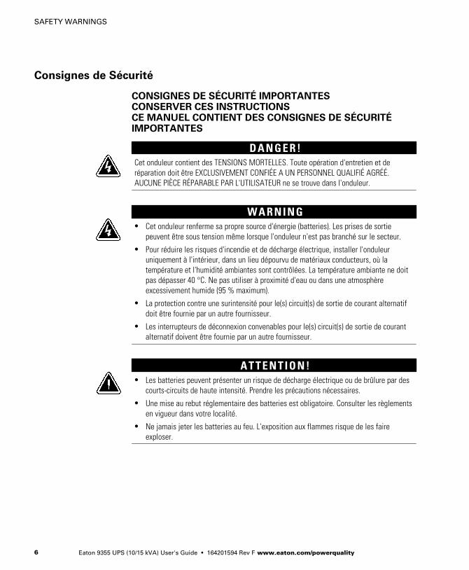
Consignes de Sécurité
CONSIGNES DE SÉCURITÉ IMPORTANTESCONSERVER CES INSTRUCTIONSCE MANUEL CONTIENT DES CONSIGNES DE SÉCURITÉIMPORTANTES
D A N G E R !Cet onduleur contient des TENSIONS MORTELLES. Toute opération d'entretien et deréparation doit être EXCLUSIVEMENT CONFIÉE A UN PERSONNEL QUALIFIÉ AGRÉÉ.AUCUNE PIÈCE RÉPARABLE PAR L'UTILISATEUR ne se trouve dans l'onduleur.
W A R N I N G� Cet onduleur renferme sa propre source d'énergie (batteries). Les prises de sortie
peuvent être sous tension même lorsque l'onduleur n'est pas branché sur le secteur.
� Pour réduire les risques d'incendie et de décharge électrique, installer l'onduleuruniquement à l'intérieur, dans un lieu dépourvu de matériaux conducteurs, où latempérature et l'humidité ambiantes sont contrôlées. La température ambiante ne doitpas dépasser 40 °C. Ne pas utiliser à proximité d'eau ou dans une atmosphèreexcessivement humide (95 % maximum).
� La protection contre une surintensité pour le(s) circuit(s) de sortie de courant alternatifdoit être fournie par un autre fournisseur.
� Les interrupteurs de déconnexion convenables pour le(s) circuit(s) de sortie de courantalternatif doivent être fournie par un autre fournisseur.
A T T E N T I O N !� Les batteries peuvent présenter un risque de décharge électrique ou de brûlure par des
courts-circuits de haute intensité. Prendre les précautions nécessaires.
� Une mise au rebut réglementaire des batteries est obligatoire. Consulter les règlementsen vigueur dans votre localité.
� Ne jamais jeter les batteries au feu. L'exposition aux flammes risque de les faireexploser.
SAFETY WARNINGS
Eaton 9355 UPS (10/15 kVA) User's Guide � 164201594 Rev F www.eaton.com/powerquality 7
Advertencias de Seguridad
INSTRUCCIONES DE SEGURIDAD IMPORTANTESGUARDE ESTAS INSTRUCCIONESESTE MANUAL CONTIENE INSTRUCCIONES DE SEGURIDADIMPORTANTES
P E L I G R OEste SIE contiene VOLTAJES MORTALES. Todas las reparaciones y el servicio técnico debenser efectuados SOLAMENTE POR PERSONAL DE SERVICIO TÉCNICO AUTORIZADO. No hayNINGUNA PARTE QUE EL USUARIO PUEDA REPARAR dentro del SIE.
W A R N I N G� Este SIE contiene su propia fuente de energía (las baterías). Los receptáculos de salida
pueden transmitir corriente eléctrica aun cuando el SIE no esté conectado a unsuministro de corriente alterna (c.a.).
� Para reducir el riesgo de incendio o de choque eléctrico, instale este SIE en un lugarcubierto, con temperatura y humedad controladas, libre de contaminantes conductores.La temperatura ambiente no debe exceder los 40°C. No trabaje cerca del agua o conhumedad excesiva (95% máximo).
� La protección contra exceso de corriente para el/los circuito(s) de CA de salida serásuministrada por terceros.
� Los interruptores de desconexión debidamente clasificados para el/los circuito(s) de CAde salida serán suministrados por terceros.
P R E C A U C I Ó N� Las baterías pueden presentar un riesgo de descargas eléctricas o de quemaduras
debido a la alta corriente de cortocircuito. Preste atención a las instruccionescorrespondientes.
� Es necesario desechar las baterías de un modo adecuado. Consulte las normas localespara conocer los requisitos pertinentes.
� Nunca deseche las baterías en el fuego. Las baterías pueden explotar si se las expone ala llama.

SAFETY WARNINGS
Eaton 9355 UPS (10/15 kVA) User's Guide � 164201594 Rev F www.eaton.com/powerquality8
Eaton 9355 UPS (10/15 kVA) User's Guide � 164201594 Rev F www.eaton.com/powerquality 9
Chapter 3 UPS Setup
This chapter describes:
� Equipment inspection
� Floor loading and clearances
� Unloading the cabinet(s)
The instructions are intended for the chief operator/system supervisor,electrical consultants, and installation electricians. Local regulations andelectrical code must be followed during the UPS installation.
Inspecting the Equipment
If any equipment has been damaged during shipment, keep the shippingand packing materials for the carrier or place of purchase and file a claimfor shipping damage. If you discover damage after acceptance, file aclaim for concealed damage.
To file a claim for shipping damage or concealed damage: 1) File withthe carrier within 15 days of receipt of the equipment; 2) Send a copy ofthe damage claim within 15 days to your service representative.
NOTE Check the battery recharge date on the packaging label. If the date has expired andthe batteries were never recharged, do not use the UPS. Contact your service representative.

UPS SETUP
Eaton 9355 UPS (10/15 kVA) User's Guide � 164201594 Rev F www.eaton.com/powerquality10
Floor Loading
When planning the installation, consider the UPS weight for floorloading. The strength of the installation surface must be adequate forpoint and distributed loadings. The approximate weights are shown inthe following table.
Standard Model Floor Loadings (2-High/3-High Cabinets)
Eaton 9355 MaximumWeight
Point Loadinglb/in2 (kg/cm2)
2-High UPS 381 lb (173 kg) 95 (6.7)
3-High UPS-32 587 lb (266 kg) 147 (10.3)
3-High UPS-64 619 lb (281 kg) 155 (10.9)
2-High EBM 480 lb (218 kg) 120 (8.4)
3-High EBM 710 lb (322 kg) 178 (12.5)
Clearances
The following clearances are recommended for the Eaton 9355 UPS:
From Front of Cabinet 36” (91.4 cm) working space
From Back of Cabinet 6” (15.2 cm) without PDM installed; with PDM installed,clearance determined by customer-supplied mating plug

UPS SETUP
Eaton 9355 UPS (10/15 kVA) User's Guide � 164201594 Rev F www.eaton.com/powerquality 11
Unloading the Cabinet(s)
The following tools are required for unloading the cabinet(s):
� 15 mm wrench or socket
� 7 mm nut driver or socket
C A U T I O NThe UPS and EBM are heavy (see page 10). Unloading the cabinets requires at least twopeople to safely remove the cabinets from the pallet.
To unload three-high cabinets or two-high EBMs, continue to thefollowing section. To unload two-high UPS cabinets, proceed to page 15.
Three-High Cabinets or Two-High EBMs
To remove a three-high cabinet or a two-high EBM from the shippingpallet:
1. Remove the two M10 bolts securing the stabilizing bracket to thepallet (see Figure 2).
M10 Bolts
Figure 2. Removing the Stabilizing Bracket Bolts
UPS SETUP
Eaton 9355 UPS (10/15 kVA) User's Guide � 164201594 Rev F www.eaton.com/powerquality12
2. Remove the four M4 screws securing the stabilizing bracket to thecabinet rear panel and remove the bracket (see Figure 3). Retain thehardware for later use.
NOTE Retain the stabilizing bracket and hardware for later re-assembly onto the cabinet.
3. Remove the front cover from the bottom cabinet to access thefront shipping bracket.
Press and release the handle latch at the bottom of the cover andthen lift the cover up and off the cabinet.
4. Remove the three M10 bolts securing the rear shipping pad to thepallet and remove the shipping pad.

UPS SETUP
Eaton 9355 UPS (10/15 kVA) User's Guide � 164201594 Rev F www.eaton.com/powerquality 13
NOTE Hold the back of the cabinet so that the bolts can be removed easily without thecabinet rolling backward.
5. Remove the two M10 bolts securing the front shipping bracket andremove the bracket.
If needed, adjust the leveling feet to release the bracket.
Stabilizing Bracket
Front ShippingBracket
Shipping Pad
M4 Screws
M10 Bolts
M10 Bolts
Figure 3. Removing the Brackets and Shipping Pad
6. Reinstall the front cover removed in Step 3.
Hang the top edge of the cover on the cabinet first, then lower thebottom edge and snap into place.

UPS SETUP
Eaton 9355 UPS (10/15 kVA) User's Guide � 164201594 Rev F www.eaton.com/powerquality14
NOTE Support the front and back of the cabinet when rolling it off the pallet to preventtipping.
7. Slowly roll the cabinet toward the rear of the pallet. Once the pallettilts, continue rolling the cabinet down the pallet until the cabinettouches the floor (see Figure 4).
If needed, adjust the leveling feet so that the cabinet rolls freely.
Figure 4. Unloading the Cabinet
8. With the cabinet supported, slowly pull the pallet away from thecabinet (see Figure 5).
Figure 5. Removing the Pallet
9. Roll the cabinet to the desired location.
10. Continue to “Selecting an Installation Option” on page 18.

UPS SETUP
Eaton 9355 UPS (10/15 kVA) User's Guide � 164201594 Rev F www.eaton.com/powerquality 15
Two-High UPS Cabinets
To remove a two-high UPS from the shipping pallet:
1. Remove the M10 bolt securing the vertical bracket to the pallet (seeFigure 6).
2. Remove and retain the three M4 screws securing the verticalbracket to the UPS. Remove the vertical bracket.
M10 Bolt
M4 Screws
Figure 6. Removing the Vertical Bracket
3. Reinstall the M4 screws to the UPS (see Figure 7).
M4 Screws
Figure 7. Reinstalling the M4 Screws
UPS SETUP
Eaton 9355 UPS (10/15 kVA) User's Guide � 164201594 Rev F www.eaton.com/powerquality16
4. Repeat Steps 1 through 3 to remove the vertical bracket on theother side.
5. Remove the front cover from the bottom cabinet to access thefront shipping bracket.
Press and release the handle latch at the bottom of the cover andthen lift the cover up and off the cabinet.
6. Remove the three M10 bolts securing the rear shipping pad to thepallet and remove the shipping pad (see Figure 8).
NOTE Hold the back of the cabinet so that the bolts can be removed easily without thecabinet rolling backward.
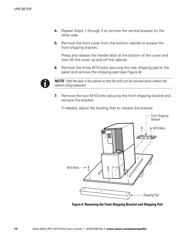
7. Remove the two M10 bolts securing the front shipping bracket andremove the bracket.
If needed, adjust the leveling feet to release the bracket.
Front ShippingBracket
Shipping Pad
M10 Bolts
M10 Bolts
Figure 8. Removing the Front Shipping Bracket and Shipping Pad

UPS SETUP
Eaton 9355 UPS (10/15 kVA) User's Guide � 164201594 Rev F www.eaton.com/powerquality 17
8. Reinstall the front cover removed in Step 5.
Hang the top edge of the cover on the cabinet first, then lower thebottom edge and snap into place.
NOTE Support the front and back of the cabinet when rolling it off the pallet to preventtipping.
9. Slowly roll the cabinet toward the rear of the pallet. Once the pallettilts, continue rolling the cabinet down the pallet until the cabinettouches the floor (see Figure 9).
If needed, adjust the leveling feet so that the cabinet rolls freely.
Figure 9. Unloading the Cabinet
UPS SETUP
Eaton 9355 UPS (10/15 kVA) User's Guide � 164201594 Rev F www.eaton.com/powerquality18
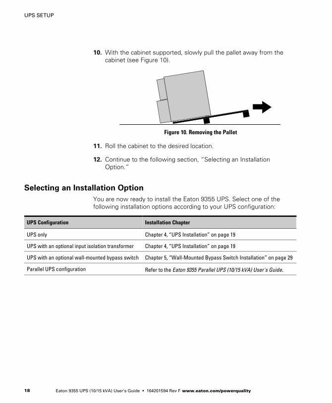
10. With the cabinet supported, slowly pull the pallet away from thecabinet (see Figure 10).
Figure 10. Removing the Pallet
11. Roll the cabinet to the desired location.
12. Continue to the following section, “Selecting an InstallationOption.”
Selecting an Installation Option
You are now ready to install the Eaton 9355 UPS. Select one of thefollowing installation options according to your UPS configuration:
UPS Configuration Installation Chapter
UPS only Chapter 4, “UPS Installation” on page 19
UPS with an optional input isolation transformer Chapter 4, “UPS Installation” on page 19
UPS with an optional wall-mounted bypass switch Chapter 5, “Wall-Mounted Bypass Switch Installation” on page 29
Parallel UPS configuration Refer to the Eaton 9355 Parallel UPS (10/15 kVA) User's Guide.
Eaton 9355 UPS (10/15 kVA) User's Guide � 164201594 Rev F www.eaton.com/powerquality 19
Chapter 4 UPS Installation
The Eaton 9355 has the following power connections:
� 3‐phase (L1, L2, and L3), neutral, and ground connection forrectifier/bypass input
� 3‐phase (L1, L2, and L3), neutral, and ground connection for loadoutput
The nominal input/output voltages are:
� 120/208 or 127/220 Vac
� 480V or 600V 60-Hz input is available using the optional input isolationtransformer module
Output overcurrent protection and disconnect switch must be providedby others.
Figure 15 through Figure 17 beginning on page 25 show the onelinediagrams.
W A R N I N GOnly qualified service personnel (such as a licensed electrician) should perform the UPSinstallation and initial startup. Risk of electrical shock.
To hardwire the UPS:
1. Verify that the electrical connections to the installation site havebeen properly installed.
2. A wall-mounted, user‐supplied, readily‐accessible disconnectiondevice must be incorporated in the input wiring.
Compare the circuit breaker ratings to the ones in Table 1 onpage 22.
NOTE To accommodate the feature of easy system expandability, it is recommended thatinitial installation of the Eaton 9355 UPS contain wiring to support the maximum capacity ofthe UPS cabinet.
3. Switch off utility power to the distribution point where the UPS willbe connected. Be absolutely sure there is no power.

UPS INSTALLATION
Eaton 9355 UPS (10/15 kVA) User's Guide � 164201594 Rev F www.eaton.com/powerquality20
4. Determine your equipment's grounding requirements according toyour local electrical code.
5. Verify that the UPS battery circuit breaker is in the OFF position(see Figure 11).
Battery Circuit Breaker
UPS WiringAccess Cover
Conduit Landing Plates
Figure 11. UPS Rear View (3-High Shown)
6. For UPS only installations, continue to Step 7; for UPS installationswith an input isolation transformer, proceed to Step 10.
7. Remove the UPS wiring access cover and one of the conduitlanding plates and retain (see Figure 11).
8. Punch two holes in the conduit landing plate for the input andoutput conduit using a Greenlee® punch or similar device.
9. Proceed to Step 12.
UPS INSTALLATION
Eaton 9355 UPS (10/15 kVA) User's Guide � 164201594 Rev F www.eaton.com/powerquality 21
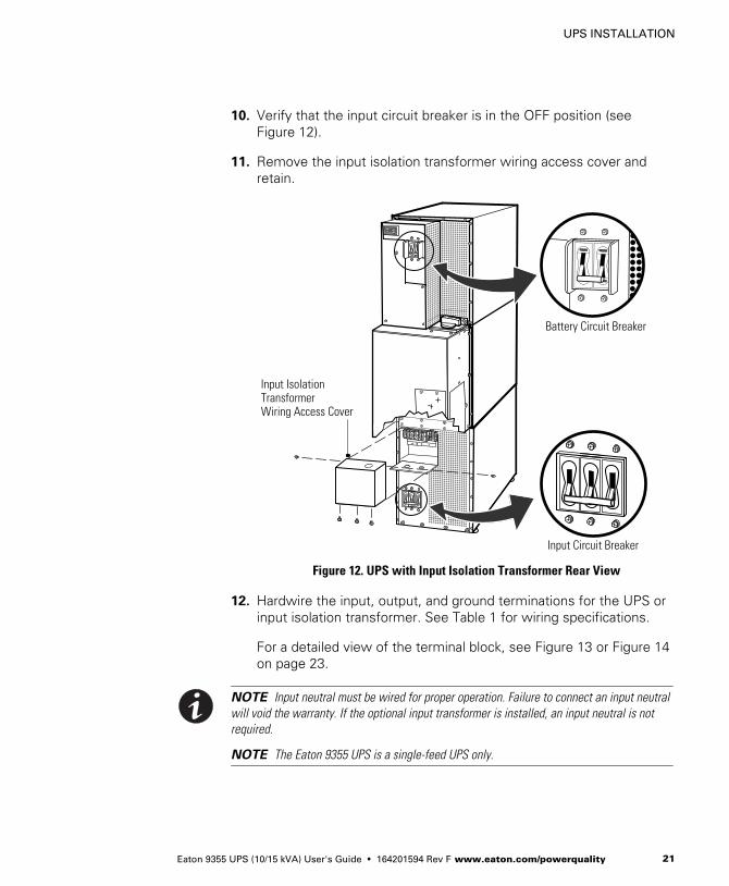
10. Verify that the input circuit breaker is in the OFF position (seeFigure 12).
11. Remove the input isolation transformer wiring access cover andretain.
Battery Circuit Breaker
Input Circuit Breaker
Input IsolationTransformer Wiring Access Cover
Figure 12. UPS with Input Isolation Transformer Rear View
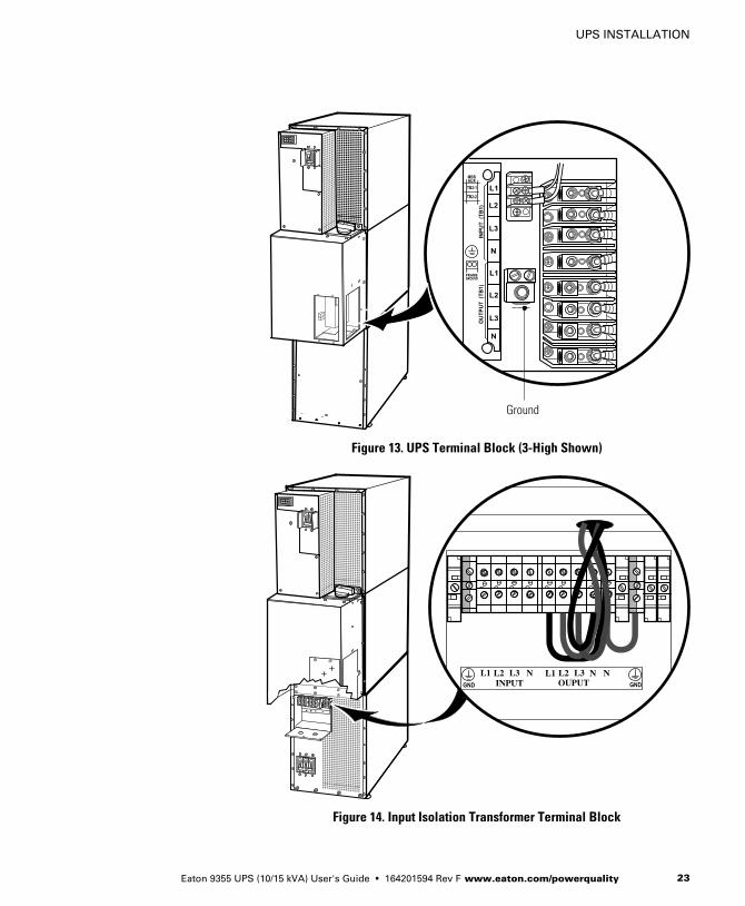
12. Hardwire the input, output, and ground terminations for the UPS orinput isolation transformer. See Table 1 for wiring specifications.
For a detailed view of the terminal block, see Figure 13 or Figure 14on page 23.
NOTE Input neutral must be wired for proper operation. Failure to connect an input neutralwill void the warranty. If the optional input transformer is installed, an input neutral is notrequired.
NOTE The Eaton 9355 UPS is a single-feed UPS only.
UPS INSTALLATION
Eaton 9355 UPS (10/15 kVA) User's Guide � 164201594 Rev F www.eaton.com/powerquality22
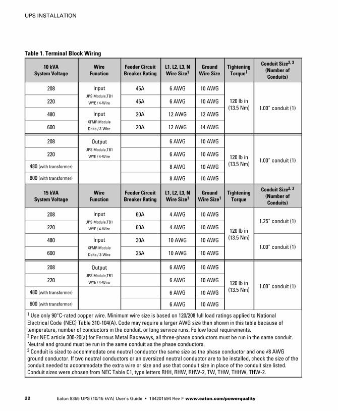
Table 1. Terminal Block Wiring
10 kVASystem Voltage
WireFunction
Feeder CircuitBreaker Rating
L1, L2, L3, NWire Size1
GroundWire Size
TighteningTorque1
Conduit Size2, 3
(Number ofConduits)
208 InputUPS Module,TB1
WYE / 4-Wire
45A 6 AWG 10 AWG
120 lb in(13.5 Nm) 1.00” conduit (1)
220 45A 6 AWG 10 AWG
480 InputXFMR Module
Delta / 3-Wire
20A 12 AWG 12 AWG
600 20A 12 AWG 14 AWG
208 OutputUPS Module,TB1
WYE / 4-Wire
6 AWG 10 AWG
120 lb in(13.5 Nm)
1.00” conduit (1)220 6 AWG 10 AWG
480 (with transformer) 8 AWG 10 AWG
600 (with transformer) 8 AWG 10 AWG
15 kVASystem Voltage
WireFunction
Feeder CircuitBreaker Rating
L1, L2, L3, NWire Size1
GroundWire Size1
TighteningTorque
Conduit Size2, 3
(Number ofConduits)
208 InputUPS Module,TB1
WYE / 4-Wire
60A 4 AWG 10 AWG
120 lb in(13.5 Nm)
1.25” conduit (1)220 60A 4 AWG 10 AWG
480 InputXFMR Module
Delta / 3-Wire
30A 10 AWG 10 AWG1.00” conduit (1)
600 25A 10 AWG 10 AWG
208 OutputUPS Module,TB1
WYE / 4-Wire
6 AWG 10 AWG
120 lb in(13.5 Nm)
1.00” conduit (1)220 6 AWG 10 AWG
480 (with transformer) 6 AWG 10 AWG
600 (with transformer) 6 AWG 10 AWG
1 Use only 90°C-rated copper wire. Minimum wire size is based on 120/208 full load ratings applied to NationalElectrical Code (NEC) Table 310‐104(A). Code may require a larger AWG size than shown in this table because oftemperature, number of conductors in the conduit, or long service runs. Follow local requirements.2 Per NEC article 300‐20(a) for Ferrous Metal Raceways, all three-phase conductors must be run in the same conduit.Neutral and ground must be run in the same conduit as the phase conductors.3 Conduit is sized to accommodate one neutral conductor the same size as the phase conductor and one #8 AWGground conductor. If two neutral conductors or an oversized neutral conductor are to be installed, check the size of theconduit needed to accommodate the extra wire or size and use that conduit size in place of the conduit size listed.Conduit sizes were chosen from NEC Table C1, type letters RHH, RHW, RHW‐2, TW, THW, THHW, THW‐2.
UPS INSTALLATION
Eaton 9355 UPS (10/15 kVA) User's Guide � 164201594 Rev F www.eaton.com/powerquality 23
Ground
Figure 13. UPS Terminal Block (3-High Shown)
L1 L2 L3 NINPUT
L1 L2 L3 NOUPUT
N
Figure 14. Input Isolation Transformer Terminal Block

UPS INSTALLATION
Eaton 9355 UPS (10/15 kVA) User's Guide � 164201594 Rev F www.eaton.com/powerquality24
13. For UPS only installations, replace the UPS wiring access cover andconduit landing plate.
For UPS installations with an input isolation transformer, replace thetransformer wiring access cover.
14. Continue to “Stabilizing the Cabinet” on page 55 to complete theUPS installation.

UPS INSTALLATION
Eaton 9355 UPS (10/15 kVA) User's Guide � 164201594 Rev F www.eaton.com/powerquality 25
*
*
Figure 15. UPS Wiring Diagram
UPS INSTALLATION
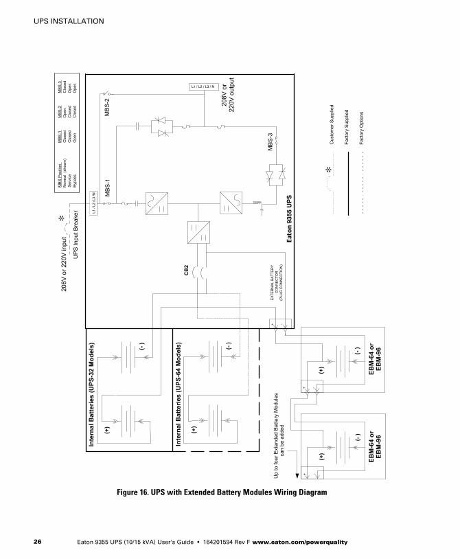
Eaton 9355 UPS (10/15 kVA) User's Guide � 164201594 Rev F www.eaton.com/powerquality26
*
*
Figure 16. UPS with Extended Battery Modules Wiring Diagram
UPS INSTALLATION
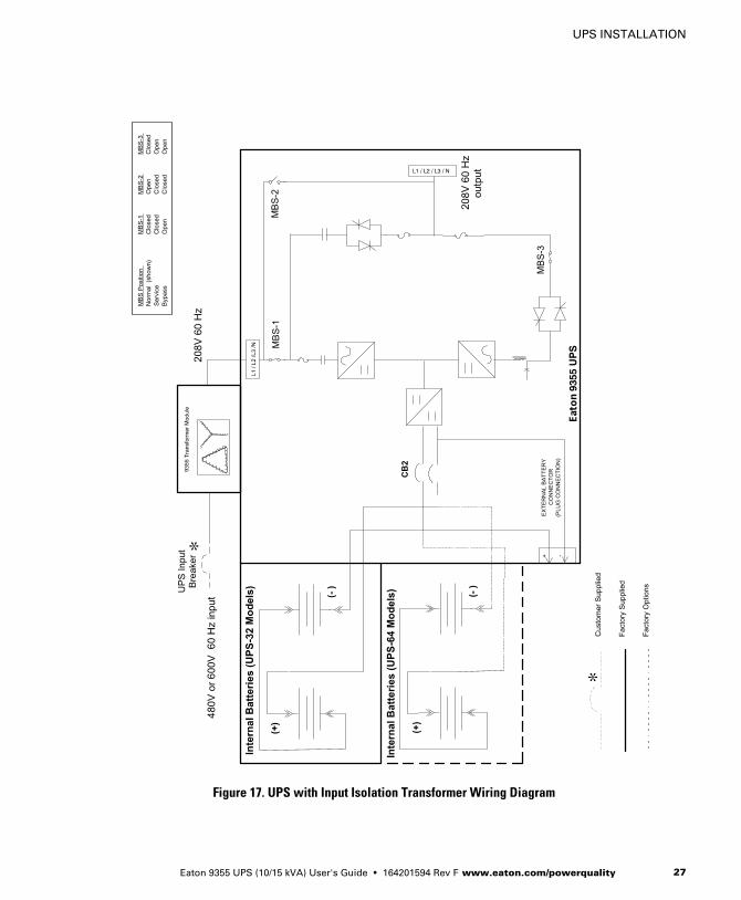
Eaton 9355 UPS (10/15 kVA) User's Guide � 164201594 Rev F www.eaton.com/powerquality 27
*
*
Figure 17. UPS with Input Isolation Transformer Wiring Diagram

UPS INSTALLATION
Eaton 9355 UPS (10/15 kVA) User's Guide � 164201594 Rev F www.eaton.com/powerquality28
Eaton 9355 UPS (10/15 kVA) User's Guide � 164201594 Rev F www.eaton.com/powerquality 29
Chapter 5 Version 1 Wall-Mounted Bypass SwitchInstallation
This chapter describes installing the wall-mounted bypass switch withthe UPS. The wall-mounted bypass switch is a Make-Before-Break(MBB) maintenance bypass switch.
NOTE The input isolation transformer cannot be used with the wall-mounted bypassswitch.
The Eaton 9355 UPS has the following power connections:
� 3‐phase (L1, L2, and L3), neutral, and ground connection forrectifier/bypass input
� 3‐phase (L1, L2, and L3), neutral, and ground connection for loadoutput
The nominal input/output voltages are:
� 120/208 or 127/220 Vac
Output overcurrent protection and disconnect switch must be providedby others.
Figure 26 and Figure 27 beginning on page 39 show the onelinediagrams.
VERSION 1 WALL-MOUNTED BYPASS SWITCH
Eaton 9355 UPS (10/15 kVA) User's Guide � 164201594 Rev F www.eaton.com/powerquality30
W A R N I N GOnly qualified service personnel (such as a licensed electrician) should perform the UPSinstallation and initial startup. Risk of electrical shock.
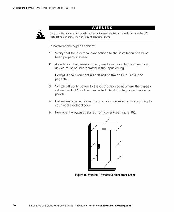
To hardwire the bypass cabinet:
1. Verify that the electrical connections to the installation site havebeen properly installed.
2. A wall-mounted, user‐supplied, readily‐accessible disconnectiondevice must be incorporated in the input wiring.
Compare the circuit breaker ratings to the ones in Table 2 onpage 34.
3. Switch off utility power to the distribution point where the bypasscabinet and UPS will be connected. Be absolutely sure there is nopower.
4. Determine your equipment's grounding requirements according toyour local electrical code.
5. Remove the bypass cabinet front cover (see Figure 18).
Figure 18. Version 1 Bypass Cabinet Front Cover

VERSION 1 WALL-MOUNTED BYPASS SWITCH
Eaton 9355 UPS (10/15 kVA) User's Guide � 164201594 Rev F www.eaton.com/powerquality 31
6. Remove the internal cover to gain access to the breakers (seeFigure 19).
InternalCover
Figure 19. Version 1 Internal Cover
VERSION 1 WALL-MOUNTED BYPASS SWITCH
Eaton 9355 UPS (10/15 kVA) User's Guide � 164201594 Rev F www.eaton.com/powerquality32
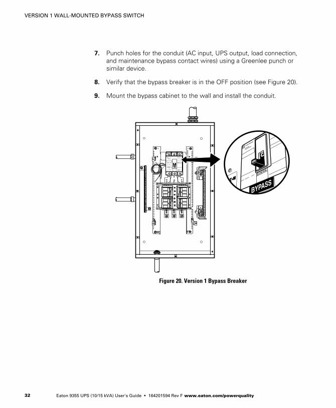
7. Punch holes for the conduit (AC input, UPS output, load connection,and maintenance bypass contact wires) using a Greenlee punch orsimilar device.
8. Verify that the bypass breaker is in the OFF position (see Figure 20).
9. Mount the bypass cabinet to the wall and install the conduit.
Figure 20. Version 1 Bypass Breaker
VERSION 1 WALL-MOUNTED BYPASS SWITCH
Eaton 9355 UPS (10/15 kVA) User's Guide � 164201594 Rev F www.eaton.com/powerquality 33
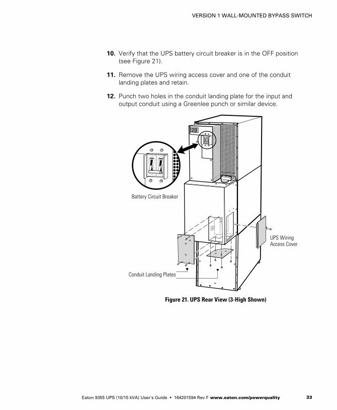
10. Verify that the UPS battery circuit breaker is in the OFF position(see Figure 21).
11. Remove the UPS wiring access cover and one of the conduitlanding plates and retain.
12. Punch two holes in the conduit landing plate for the input andoutput conduit using a Greenlee punch or similar device.
Battery Circuit Breaker
UPS WiringAccess Cover
Conduit Landing Plates
Figure 21. UPS Rear View (3-High Shown)
VERSION 1 WALL-MOUNTED BYPASS SWITCH
Eaton 9355 UPS (10/15 kVA) User's Guide � 164201594 Rev F www.eaton.com/powerquality34
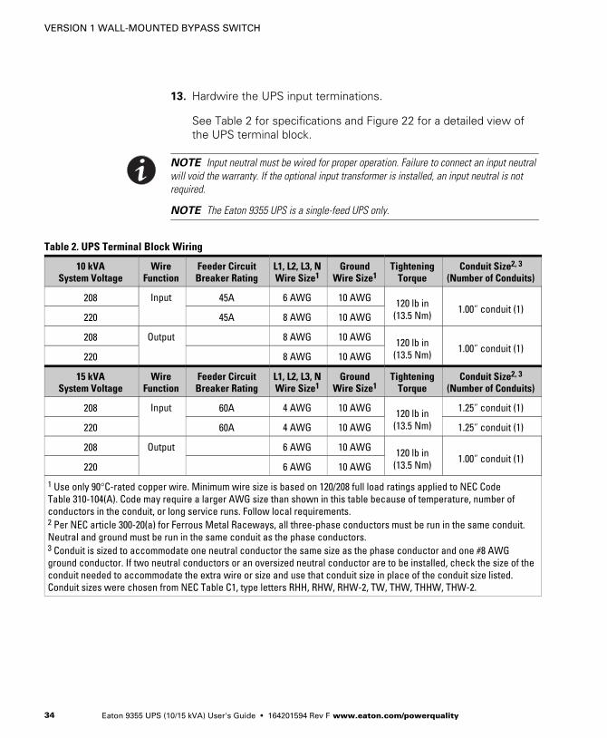
13. Hardwire the UPS input terminations.
See Table 2 for specifications and Figure 22 for a detailed view ofthe UPS terminal block.
NOTE Input neutral must be wired for proper operation. Failure to connect an input neutralwill void the warranty. If the optional input transformer is installed, an input neutral is notrequired.
NOTE The Eaton 9355 UPS is a single-feed UPS only.
Table 2. UPS Terminal Block Wiring
10 kVASystem Voltage
WireFunction
Feeder CircuitBreaker Rating
L1, L2, L3, NWire Size1
GroundWire Size1
TighteningTorque
Conduit Size2, 3
(Number of Conduits)
208 Input 45A 6 AWG 10 AWG 120 lb in(13.5 Nm)
1.00” conduit (1)220 45A 8 AWG 10 AWG
208 Output 8 AWG 10 AWG 120 lb in(13.5 Nm)
1.00” conduit (1)220 8 AWG 10 AWG
15 kVASystem Voltage
WireFunction
Feeder CircuitBreaker Rating
L1, L2, L3, NWire Size1
GroundWire Size1
TighteningTorque
Conduit Size2, 3
(Number of Conduits)
208 Input 60A 4 AWG 10 AWG 120 lb in(13.5 Nm)
1.25” conduit (1)
220 60A 4 AWG 10 AWG 1.25” conduit (1)
208 Output 6 AWG 10 AWG 120 lb in(13.5 Nm)
1.00” conduit (1)220 6 AWG 10 AWG
1 Use only 90°C-rated copper wire. Minimum wire size is based on 120/208 full load ratings applied to NEC CodeTable 310‐104(A). Code may require a larger AWG size than shown in this table because of temperature, number ofconductors in the conduit, or long service runs. Follow local requirements.2 Per NEC article 300‐20(a) for Ferrous Metal Raceways, all three-phase conductors must be run in the same conduit.Neutral and ground must be run in the same conduit as the phase conductors.3 Conduit is sized to accommodate one neutral conductor the same size as the phase conductor and one #8 AWGground conductor. If two neutral conductors or an oversized neutral conductor are to be installed, check the size of theconduit needed to accommodate the extra wire or size and use that conduit size in place of the conduit size listed.Conduit sizes were chosen from NEC Table C1, type letters RHH, RHW, RHW‐2, TW, THW, THHW, THW‐2.

VERSION 1 WALL-MOUNTED BYPASS SWITCH
Eaton 9355 UPS (10/15 kVA) User's Guide � 164201594 Rev F www.eaton.com/powerquality 35
Ground
MaintenanceBypassContacts
TB2
Figure 22. UPS Terminal Block (3-High Shown)

VERSION 1 WALL-MOUNTED BYPASS SWITCH
Eaton 9355 UPS (10/15 kVA) User's Guide � 164201594 Rev F www.eaton.com/powerquality36
14. Hardwire the output terminations from the UPS to the bypasscabinet (see Figure 23).
Neutral
Line 1Line 2Line 3
Ground
Figure 23. Version 1 UPS Output to Bypass Cabinet Wiring
VERSION 1 WALL-MOUNTED BYPASS SWITCH
Eaton 9355 UPS (10/15 kVA) User's Guide � 164201594 Rev F www.eaton.com/powerquality 37
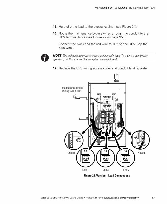
15. Hardwire the load to the bypass cabinet (see Figure 24).
16. Route the maintenance bypass wires through the conduit to theUPS terminal block (see Figure 22 on page 35).
Connect the black and the red wire to TB2 on the UPS. Cap theblue wire.
NOTE The maintenance bypass contacts are normally-open. To ensure proper bypassoperation, DO NOT use the blue wire (it is normally-closed).
17. Replace the UPS wiring access cover and conduit landing plate.
Ground
Line 1
Neutral
Line 2 Line 3
Maintenance BypassWiring to UPS TB2
Figure 24. Version 1 Load Connections
VERSION 1 WALL-MOUNTED BYPASS SWITCH
Eaton 9355 UPS (10/15 kVA) User's Guide � 164201594 Rev F www.eaton.com/powerquality38
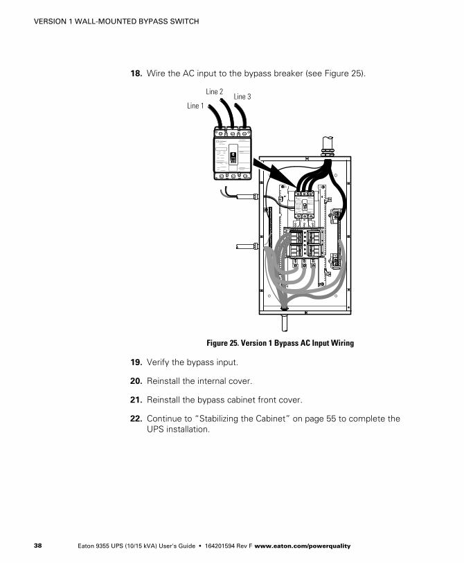
18. Wire the AC input to the bypass breaker (see Figure 25).
Line 1
Line 2Line 3
Figure 25. Version 1 Bypass AC Input Wiring
19. Verify the bypass input.
20. Reinstall the internal cover.
21. Reinstall the bypass cabinet front cover.
22. Continue to “Stabilizing the Cabinet” on page 55 to complete theUPS installation.
VERSION 1 WALL-MOUNTED BYPASS SWITCH
Eaton 9355 UPS (10/15 kVA) User's Guide � 164201594 Rev F www.eaton.com/powerquality 39
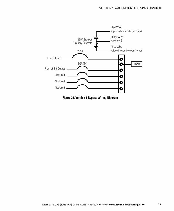
Not Used
Not Used
Not Used
Red Wire(open when breaker is open)
Bypass Input
Black Wire(common)
From UPS 1 Output
225A
80A (4X) LOAD
Blue Wire(closed when breaker is open)
225A BreakerAuxiliary Contacts
Figure 26. Version 1 Bypass Wiring Diagram

VERSION 1 WALL-MOUNTED BYPASS SWITCH
Eaton 9355 UPS (10/15 kVA) User's Guide � 164201594 Rev F www.eaton.com/powerquality40
*
Figure 27. UPS with Input Isolation Transformer and Version 1 Wall Mounted Bypass Cabinet Wiring Diagram

Eaton 9355 UPS (10/15 kVA) User's Guide � 164201594 Rev F www.eaton.com/powerquality 41
Chapter 6 Version 2 Wall-Mounted Bypass SwitchInstallation
This chapter describes installing the wall-mounted bypass switch withthe UPS. The wall-mounted bypass switch is a Make-Before-Break(MBB) maintenance bypass switch.
NOTE The input isolation transformer cannot be used with the wall-mounted bypassswitch.
The Eaton 9355 UPS has the following power connections:
� 3‐phase (L1, L2, and L3), neutral, and ground connection forrectifier/bypass input
� 3‐phase (L1, L2, and L3), neutral, and ground connection for loadoutput
The nominal input/output voltages are:
� 120/208 or 127/220 Vac
Output overcurrent protection and disconnect switch must be providedby others.
Figure 37 through Figure 39 beginning on page 53 show the onelinediagrams.

VERSION 2 WALL-MOUNTED BYPASS SWITCH
Eaton 9355 UPS (10/15 kVA) User's Guide � 164201594 Rev F www.eaton.com/powerquality42
W A R N I N GOnly qualified service personnel (such as a licensed electrician) should perform the UPSinstallation and initial startup. Risk of electrical shock.
To hardwire the bypass cabinet:
1. Verify that the electrical connections to the installation site havebeen properly installed.
2. A wall-mounted, user‐supplied, readily‐accessible disconnectiondevice must be incorporated in the input wiring.
Compare the circuit breaker ratings to the ones in Table 3 onpage 47.
3. Switch off utility power to the distribution point where the bypasscabinet and UPS will be connected. Be absolutely sure there is nopower.
4. Determine your equipment's grounding requirements according toyour local electrical code.
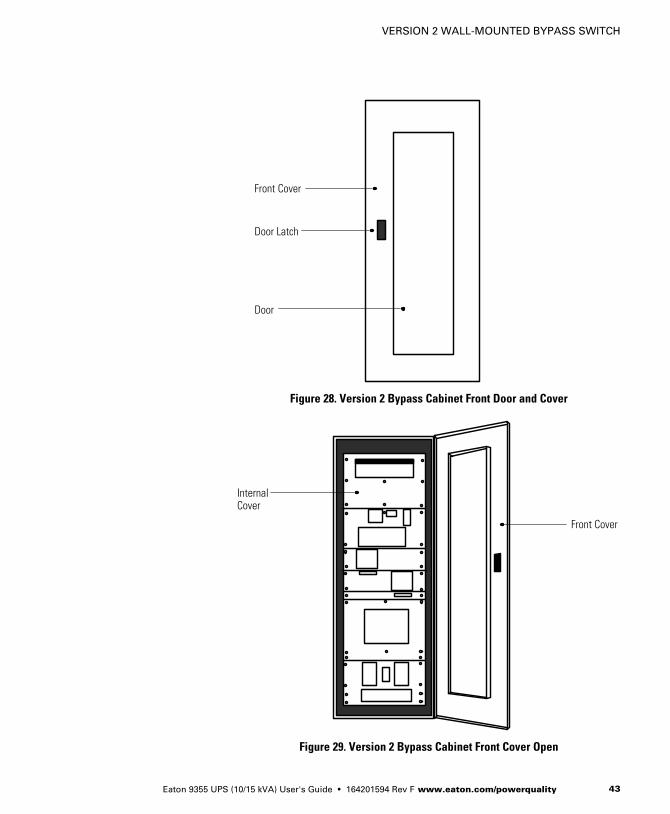
5. Unfasten the bypass cabinet front door latch and swing the dooropen (see Figure 28).
6. Follow the instructions on the inside of the door to open or removethe front cover (see Figure 28 and Figure 29).
VERSION 2 WALL-MOUNTED BYPASS SWITCH
Eaton 9355 UPS (10/15 kVA) User's Guide � 164201594 Rev F www.eaton.com/powerquality 43
Door Latch
Door
Front Cover
Figure 28. Version 2 Bypass Cabinet Front Door and Cover
InternalCover
Front Cover
Figure 29. Version 2 Bypass Cabinet Front Cover Open

VERSION 2 WALL-MOUNTED BYPASS SWITCH
Eaton 9355 UPS (10/15 kVA) User's Guide � 164201594 Rev F www.eaton.com/powerquality44
7. Remove the internal cover to gain access to the breakers (seeFigure 30).
InternalCover
Figure 30. Version 2 Bypass Cabinet Internal Cover
VERSION 2 WALL-MOUNTED BYPASS SWITCH
Eaton 9355 UPS (10/15 kVA) User's Guide � 164201594 Rev F www.eaton.com/powerquality 45
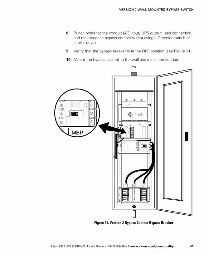
8. Punch holes for the conduit (AC input, UPS output, load connection,and maintenance bypass contact wires) using a Greenlee punch orsimilar device.
9. Verify that the bypass breaker is in the OFF position (see Figure 31).
10. Mount the bypass cabinet to the wall and install the conduit.
Figure 31. Version 2 Bypass Cabinet Bypass Breaker

VERSION 2 WALL-MOUNTED BYPASS SWITCH
Eaton 9355 UPS (10/15 kVA) User's Guide � 164201594 Rev F www.eaton.com/powerquality46
11. Verify that the UPS battery circuit breaker is in the OFF position(see Figure 32).
12. Remove the UPS wiring access cover and one of the conduitlanding plates and retain.
13. Punch two holes in the conduit landing plate for the input andoutput conduit using a Greenlee punch or similar device.
Battery Circuit Breaker
UPS WiringAccess Cover
Conduit Landing Plates
Figure 32. UPS Rear View (3-High Shown)
VERSION 2 WALL-MOUNTED BYPASS SWITCH
Eaton 9355 UPS (10/15 kVA) User's Guide � 164201594 Rev F www.eaton.com/powerquality 47
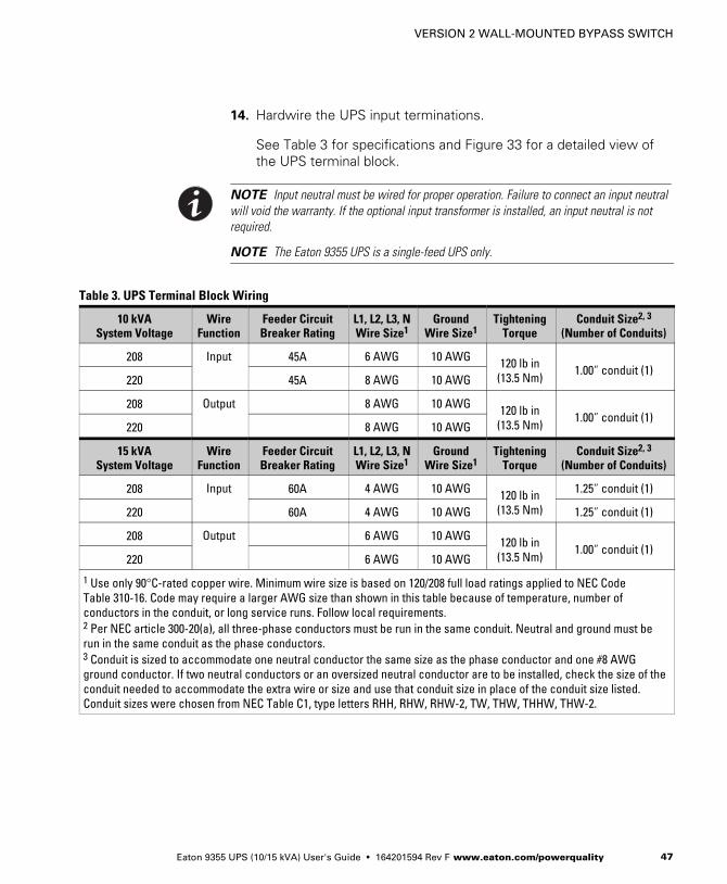
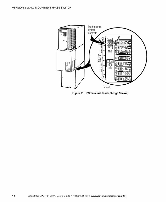
14. Hardwire the UPS input terminations.
See Table 3 for specifications and Figure 33 for a detailed view ofthe UPS terminal block.
NOTE Input neutral must be wired for proper operation. Failure to connect an input neutralwill void the warranty. If the optional input transformer is installed, an input neutral is notrequired.
NOTE The Eaton 9355 UPS is a single-feed UPS only.
Table 3. UPS Terminal Block Wiring
10 kVASystem Voltage
WireFunction
Feeder CircuitBreaker Rating
L1, L2, L3, NWire Size1
GroundWire Size1
TighteningTorque
Conduit Size2, 3
(Number of Conduits)
208 Input 45A 6 AWG 10 AWG 120 lb in(13.5 Nm)
1.00” conduit (1)220 45A 8 AWG 10 AWG
208 Output 8 AWG 10 AWG 120 lb in(13.5 Nm)
1.00” conduit (1)220 8 AWG 10 AWG
15 kVASystem Voltage
WireFunction
Feeder CircuitBreaker Rating
L1, L2, L3, NWire Size1
GroundWire Size1
TighteningTorque
Conduit Size2, 3
(Number of Conduits)
208 Input 60A 4 AWG 10 AWG 120 lb in(13.5 Nm)
1.25” conduit (1)
220 60A 4 AWG 10 AWG 1.25” conduit (1)
208 Output 6 AWG 10 AWG 120 lb in(13.5 Nm)
1.00” conduit (1)220 6 AWG 10 AWG
1 Use only 90°C-rated copper wire. Minimum wire size is based on 120/208 full load ratings applied to NEC CodeTable 310‐16. Code may require a larger AWG size than shown in this table because of temperature, number ofconductors in the conduit, or long service runs. Follow local requirements.2 Per NEC article 300‐20(a), all three-phase conductors must be run in the same conduit. Neutral and ground must berun in the same conduit as the phase conductors.3 Conduit is sized to accommodate one neutral conductor the same size as the phase conductor and one #8 AWGground conductor. If two neutral conductors or an oversized neutral conductor are to be installed, check the size of theconduit needed to accommodate the extra wire or size and use that conduit size in place of the conduit size listed.Conduit sizes were chosen from NEC Table C1, type letters RHH, RHW, RHW‐2, TW, THW, THHW, THW‐2.
VERSION 2 WALL-MOUNTED BYPASS SWITCH
Eaton 9355 UPS (10/15 kVA) User's Guide � 164201594 Rev F www.eaton.com/powerquality48
Ground
MaintenanceBypassContacts
TB2
Figure 33. UPS Terminal Block (3-High Shown)
VERSION 2 WALL-MOUNTED BYPASS SWITCH
Eaton 9355 UPS (10/15 kVA) User's Guide � 164201594 Rev F www.eaton.com/powerquality 49
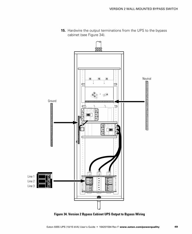
15. Hardwire the output terminations from the UPS to the bypasscabinet (see Figure 34).
Neutral
Line 1Line 2Line 3
Ground
Figure 34. Version 2 Bypass Cabinet UPS Output to Bypass Wiring
VERSION 2 WALL-MOUNTED BYPASS SWITCH
Eaton 9355 UPS (10/15 kVA) User's Guide � 164201594 Rev F www.eaton.com/powerquality50
16. Hardwire the load to the bypass cabinet (see Figure 35).
17. Route the maintenance bypass wires through the conduit to theUPS terminal block (see Figure 33 on page 48).
Connect the black and the red wires from the terminal block on theTie Cabinet to TB2 on the UPS.
NOTE The maintenance bypass contacts are normally-open. To ensure proper bypassoperation, DO NOT use the blue wire (it is normally-closed).
18. Replace the UPS wiring access cover and conduit landing plate.

VERSION 2 WALL-MOUNTED BYPASS SWITCH
Eaton 9355 UPS (10/15 kVA) User's Guide � 164201594 Rev F www.eaton.com/powerquality 51
Line 1 Line 2 Line 3
Ground
Neutral
Maintenance BypassWiring to UPS TB2
Figure 35. Version 2 Bypass Cabinet Load Connections
VERSION 2 WALL-MOUNTED BYPASS SWITCH
Eaton 9355 UPS (10/15 kVA) User's Guide � 164201594 Rev F www.eaton.com/powerquality52
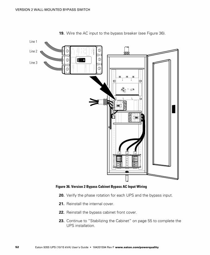
19. Wire the AC input to the bypass breaker (see Figure 36).
Line 1
Line 2
Line 3
Figure 36. Version 2 Bypass Cabinet Bypass AC Input Wiring
20. Verify the phase rotation for each UPS and the bypass input.
21. Reinstall the internal cover.
22. Reinstall the bypass cabinet front cover.
23. Continue to “Stabilizing the Cabinet” on page 55 to complete theUPS installation.

VERSION 2 WALL-MOUNTED BYPASS SWITCH
Eaton 9355 UPS (10/15 kVA) User's Guide � 164201594 Rev F www.eaton.com/powerquality 53
Not Used
Not Used
Not Used
Red Wire(open when breaker is open)
Bypass Input
Black Wire(common)
From UPS 1 Output
225A
80A (4X) LOAD
Blue Wire(closed when breaker is open)
225A BreakerAuxiliary Contacts
Figure 37. Version 2 Bypass Cabinet Bypass Wiring Diagram – without Maintenance Isolation Switch (MIS)
Red Wires(open when breaker is open)
Black Wires(common)
Blue Wires(closed when breaker is open)
225A BreakerAuxiliary Contacts
Not Used
Not Used
Not Used
Bypass Input
From UPS 1 Output
225A
110A (4X) LOAD
MIS225A
80A (4X)
Figure 38. Version 2 Bypass Cabinet Bypass Wiring Diagram – with MIS
VERSION 2 WALL-MOUNTED BYPASS SWITCH
Eaton 9355 UPS (10/15 kVA) User's Guide � 164201594 Rev F www.eaton.com/powerquality54
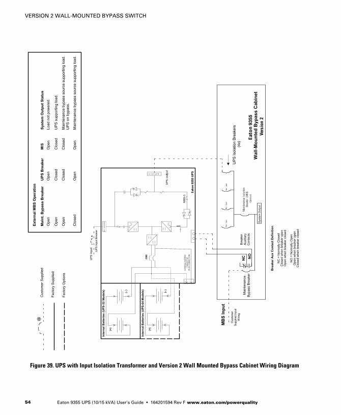
*
Figure 39. UPS with Input Isolation Transformer and Version 2 Wall Mounted Bypass Cabinet Wiring Diagram
Eaton 9355 UPS (10/15 kVA) User's Guide � 164201594 Rev F www.eaton.com/powerquality 55
Chapter 7 Stabilizing the Cabinet
NOTE For seismic installations, you MUST order and install an Eaton 9355 UPS seismic kit;do not use the following instructions.
NOTE For non-seismic installations, you MUST install the stabilizing bracket on all 3-highcabinets. The stabilizing bracket is optional for 2-high cabinets.
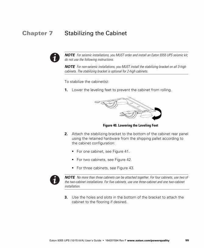
To stabilize the cabinet(s):
1. Lower the leveling feet to prevent the cabinet from rolling.
Figure 40. Lowering the Leveling Feet
2. Attach the stabilizing bracket to the bottom of the cabinet rear panelusing the retained hardware from the shipping pallet according tothe cabinet configuration:
� For one cabinet, see Figure 41.
� For two cabinets, see Figure 42.
� For three cabinets, see Figure 43.
NOTE No more than three cabinets can be attached together. For four cabinets, use two ofthe two-cabinet installations. For five cabinets, use one three-cabinet and one two-cabinetinstallation.
3. Use the holes and slots in the bottom of the bracket to attach thecabinet to the flooring if desired.

STABILIZING THE CABINET
Eaton 9355 UPS (10/15 kVA) User's Guide � 164201594 Rev F www.eaton.com/powerquality56
4. Continue to one of the following sections:
� “Extended Battery Module Installation” on page 59 to installoptional EBMs.
� “Communication” on page 63 to install UPS communicationoptions, such as X-Slot cards or remote emergency power-off(REPO).
� “Operation” on page 81 to start up the UPS.
NOTE After UPS startup, ensure maximum battery runtime by configuring the UPS for thecorrect number of EBMs (see page 91).
M4 Screws
Figure 41. Stabilizing Bracket with One Cabinet

STABILIZING THE CABINET
Eaton 9355 UPS (10/15 kVA) User's Guide � 164201594 Rev F www.eaton.com/powerquality 57
M4 Screws
Figure 42. Stabilizing Bracket with Two Cabinets
M4 Screws
Figure 43. Stabilizing Bracket with Three Cabinets

STABILIZING THE CABINET
Eaton 9355 UPS (10/15 kVA) User's Guide � 164201594 Rev F www.eaton.com/powerquality58

Eaton 9355 UPS (10/15 kVA) User's Guide � 164201594 Rev F www.eaton.com/powerquality 59
Chapter 8 Extended Battery Module Installation
NOTE A maximum of 22 battery strings can be installed in one configuration, includingUPS batteries (4 EBM-64 models or 3 EBM-96 models). UPS-32 models contain 2 strings;UPS-64 models contain 4 strings; EBM-64 models contain 4 strings; and EBM-96 modelscontain 6 strings.
NOTE For non-seismic installations, you MUST install the stabilizing bracket on all 3-highcabinets. The stabilizing bracket is optional for 2-high cabinets.
To install the optional Extended Battery Module (EBM):
1. Position the EBM adjacent to the next cabinet.
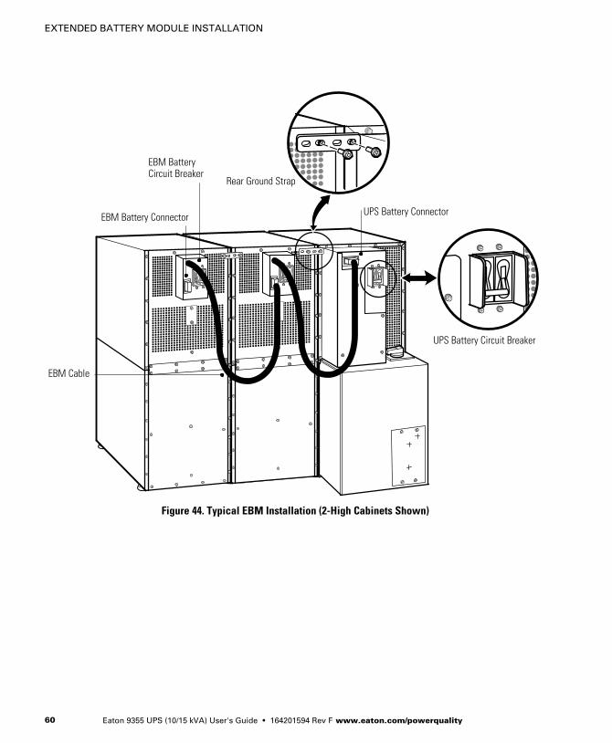
2. Verify that all battery circuit breakers are in the OFF position (seeFigure 44).
3. Remove the two ground straps from the EBM rear panel.
4. Install one ground strap between the UPS and EBM rear panels asshown in Figure 44.
5. If additional EBMs are installed, attach another ground strapbetween the first and second EBM as shown in Figure 44. Repeatfor each additional EBM.
6. Plug the EBM cable into the UPS battery connector.
7. If additional EBMs are installed, plug the EBM cable of the secondcabinet into the battery connector on the first EBM. Repeat for eachadditional EBM.
EXTENDED BATTERY MODULE INSTALLATION
Eaton 9355 UPS (10/15 kVA) User's Guide � 164201594 Rev F www.eaton.com/powerquality60
UPS Battery Connector
Rear Ground Strap
EBM Battery Circuit Breaker
EBM Battery Connector
EBM Cable
UPS Battery Circuit Breaker
Figure 44. Typical EBM Installation (2-High Cabinets Shown)

EXTENDED BATTERY MODULE INSTALLATION
Eaton 9355 UPS (10/15 kVA) User's Guide � 164201594 Rev F www.eaton.com/powerquality 61
8. Remove the top front covers of all cabinets.
9. Install the remaining ground straps between each cabinet (seeFigure 45).
10. Reinstall the top front covers removed in Step 8.
Hang the top edge of the cover on the cabinet first, then lower thebottom edge and snap into place.
11. Continue to one of the following sections:
� “Communication” on page 63 to install UPS communicationoptions, such as X-Slot cards or remote emergency power-off.
� “Operation” on page 81 to start up the UPS.
NOTE After UPS startup, ensure maximum battery runtime by configuring the UPS for thecorrect number of EBMs (see page 91).
Front Ground Strap
Figure 45. Front Ground Strap Installation (2-High Cabinets Shown)

EXTENDED BATTERY MODULE INSTALLATION
Eaton 9355 UPS (10/15 kVA) User's Guide � 164201594 Rev F www.eaton.com/powerquality62

Eaton 9355 UPS (10/15 kVA) User's Guide � 164201594 Rev F www.eaton.com/powerquality 63
Chapter 9 Communication
This section describes the:
� DB-9 communication port
� X-Slot cards
� Remote Monitor Panel and Industrial Relay Card (IRC)
� Power Management Software
� Remote emergency power-off (REPO)
� Relay output contacts
� Programmable signal inputs
Figure 46 shows the location of the communication options and controlterminals on the UPS.
12
1212
12
123
DB-9 Communication Port
REPO (normally closed)REPO (normally open)
Signal Input 2
Signal Input 1
X-Slot Communication Bay #2
X-Slot Communication Bay #1
Relay Output Contacts
Figure 46. Communication Options and Control Terminals

COMMUNICATION
Eaton 9355 UPS (10/15 kVA) User's Guide � 164201594 Rev F www.eaton.com/powerquality64
Installing Communication Options and Control Terminals
To access and install the communication options and control terminals:
1. Remove the front covers of all cabinets, starting with the topcabinet.
Press and release the handle latch at the bottom of each cover andthen lift the cover up and off the cabinet (see Figure 47).
Figure 47. Removing the Front Covers
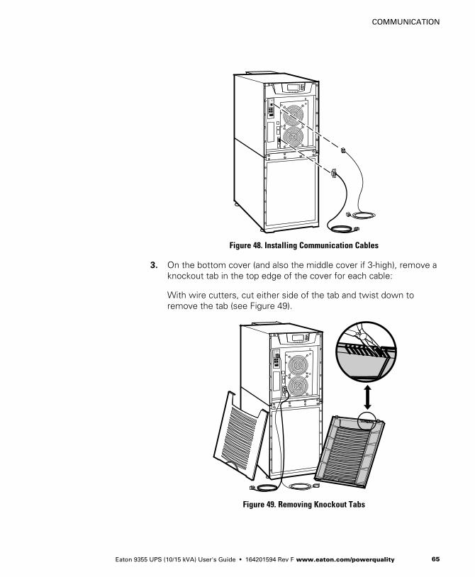
2. Install the appropriate X-Slot card and/or necessary cable(s) into thetop cabinet (see Figure 46 and Figure 48).
COMMUNICATION
Eaton 9355 UPS (10/15 kVA) User's Guide � 164201594 Rev F www.eaton.com/powerquality 65
Figure 48. Installing Communication Cables
3. On the bottom cover (and also the middle cover if 3-high), remove aknockout tab in the top edge of the cover for each cable:
With wire cutters, cut either side of the tab and twist down toremove the tab (see Figure 49).
Figure 49. Removing Knockout Tabs

COMMUNICATION
Eaton 9355 UPS (10/15 kVA) User's Guide � 164201594 Rev F www.eaton.com/powerquality66
4. Route the cable(s) to the approximate location of the cover accessholes.
5. Connect the cables to the appropriate location.
See “Communication Options” on page 67 or “Control Terminals”on page 76 for detailed information.
6. Reinstall the front covers, starting with the bottom cabinet (seeFigure 50).
Hang the top edge of the cover on the cabinet first, then lower thebottom edge and snap into place. Verify that the cables fit in theaccess holes in the covers.
Figure 50. Reinstalling the Front Covers
7. Continue to “Operation” on page 81 to start up the UPS.
NOTE After UPS startup, ensure maximum battery runtime by configuring the UPS for thecorrect number of EBMs (see page 91).

COMMUNICATION
Eaton 9355 UPS (10/15 kVA) User's Guide � 164201594 Rev F www.eaton.com/powerquality 67
Communication Options
The Eaton 9355 UPS has serial communication capabilities through theDB-9 communication port or through an X-Slot card in one of theavailable bays. In addition, the power management software can beinstalled and used to communicate with the UPS via one of the serialcommunication connections.
The UPS supports two serial communication devices according to thefollowing table:
Independent Multiplexed
X-Slot 1 X-Slot 2 DB-9 Communication Port
Any X-Slot card Any X-Slot card except the EatonModem Card
Not in use
Any X-Slot card Eaton Relay Interface CardPowerware Hot Sync CAN Bridge Card
Available
Any X-Slot card Not in use Available
NOTE You can configure relays, signal inputs, and the serial port baud rate through thefront panel menus (see Table 9 on page 84).
DB-9 Communication Port
To establish communication between the UPS and a computer, connectyour computer to the UPS communication port using the suppliedcommunication cable.
When the communication cable is installed, power managementsoftware can exchange data with the UPS. The software polls the UPSfor detailed information on the status of the power environment. If apower emergency occurs, the software initiates the saving of all dataand an orderly shutdown of the equipment.

COMMUNICATION
Eaton 9355 UPS (10/15 kVA) User's Guide � 164201594 Rev F www.eaton.com/powerquality68
The cable pins are identified in Figure 51 and the pin functions aredescribed in Table 4. See Figure 46 on page 63 for the communicationport location.
38
7
9
16
2
4
5
Figure 51. Communication Port
Table 4. Communication Port Pin Assignment
Pin Number Signal Name Function Direction from the UPS
2 TxD Transmit to external device Out
3 RxD Receive from external device In
5 GND Signal common (tied to chassis) —
X-Slot Cards
X-Slot cards allow the UPS to communicate in a variety of networkingenvironments and with different types of devices. The Eaton 9355 UPShas two available communication bays for any X-Slot card, including:
� ConnectUPS -X Web/SNMP Card - has SNMP and HTTP capabilitiesas well as monitoring through a Web browser interface; connects to atwisted-pair Ethernet (10/100BaseT) network. It has a built-inswitching hub that allows three additional network devices to beconnected to the network without the requirement of additionalnetwork drops. In addition, a Environmental Monitoring Probe can beattached to obtain humidity, temperature, smoke alarm, and securityinformation.
� Relay Interface Card - has isolated dry contact (Form-C) relay outputsfor UPS status: Utility failure, Low battery, UPS alarm/OK, or Onbypass.
� Modbus® Card - allows you to continuously and reliably monitor theUPSs in your Building Management System (BMS).
�

COMMUNICATION
Eaton 9355 UPS (10/15 kVA) User's Guide � 164201594 Rev F www.eaton.com/powerquality 69
� Industrial Relay Card - is used to indicate the operating status of theUPS using the customer's monitoring equipment and to connect anoptional RMP. The IRC uses four isolated normally-open ornormally-closed dry relay contacts to indicate the UPS status. Normal,Bypass, Battery, and Alarm mode can be monitored (see page 74 formore information).
� Multi-Server Card - has six serial communication ports that cancommunicate simultaneously with other computers using powermanagement software (provided on the Software Suite CD).
� Modem Card - provides out-of-band remote notification andmonitoring using modem communication directly to cell phones andpagers.
� Single-Port Card - connects to the Expansion Chassis to enablemultiple communication options or to a PC for power managementcontrol.
� ConnectUPS-MX SNMP Card - has Ethernet, modem, and SNMPcapabilities.
� USB Card - connects to a USB port on your computer.
NOTE The Eaton 9355 UPS does not detect plug-and-play hardware. Before installing theUSB Card, set the UPS baud rate to 1200 through the front panel (see Table 9 on page 84).
See Figure 46 on page 63 for the location of the two X-Slotcommunication bays.
Relay Interface Card
Modbus Card
Multi-Server Card
Modem Card
Single-Port Card
ConnectUPS-X Web/SNMP Card
Industrial Relay Card ConnectUPS-MX SNMP Card
USB Card
Figure 52. Optional X-Slot Cards
COMMUNICATION
Eaton 9355 UPS (10/15 kVA) User's Guide � 164201594 Rev F www.eaton.com/powerquality70
Remote Monitor Panel
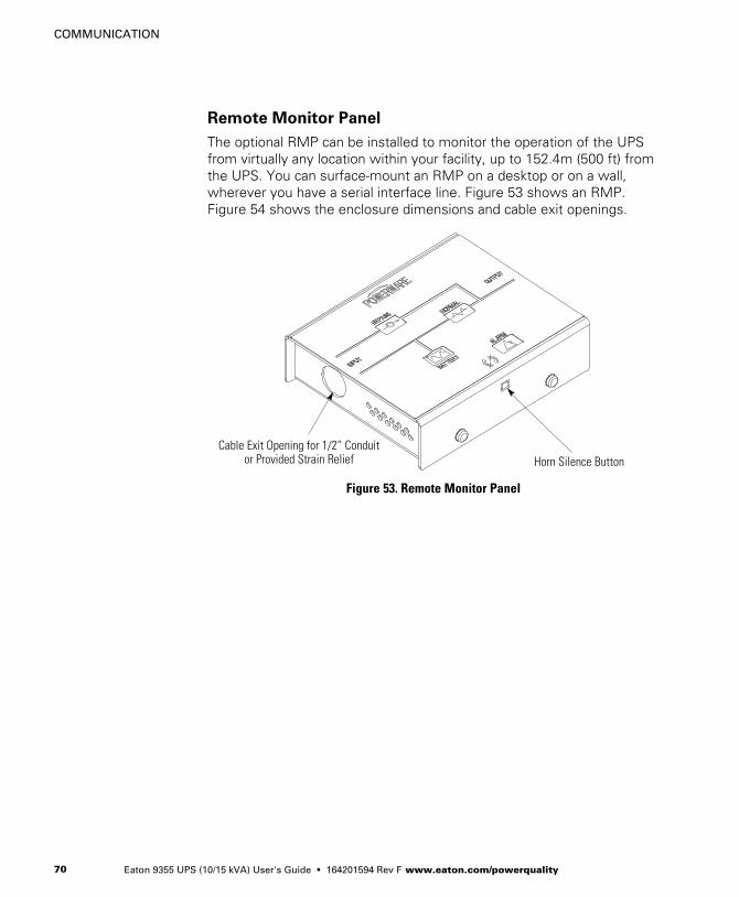
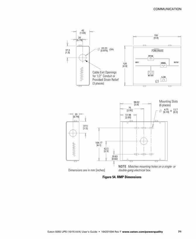
The optional RMP can be installed to monitor the operation of the UPSfrom virtually any location within your facility, up to 152.4m (500 ft) fromthe UPS. You can surface‐mount an RMP on a desktop or on a wall,wherever you have a serial interface line. Figure 53 shows an RMP.Figure 54 shows the enclosure dimensions and cable exit openings.
Horn Silence ButtonCable Exit Opening for 1/2” Conduit
or Provided Strain Relief
Figure 53. Remote Monitor Panel
COMMUNICATION
Eaton 9355 UPS (10/15 kVA) User's Guide � 164201594 Rev F www.eaton.com/powerquality 71
Mounting Slots(6 places)
NOTE Matches mounting holes on a single- ordouble-gang electrical box.
Cable Exit Openings for 1/2” Conduit orProvided Strain Relief(3 places)
Dimensions are in mm [inches]
Figure 54. RMP Dimensions

COMMUNICATION
Eaton 9355 UPS (10/15 kVA) User's Guide � 164201594 Rev F www.eaton.com/powerquality72
To install an RMP:
NOTE If mounting to a hollow wall, secure the enclosure bottom to a wood or metal studwithin the wall. Do not use hollow wall anchors. The RMP can also be mounted to a single-or double-gang electrical box.
1. If wall mounting, securely mount the RMP. Continue to Step 2.
If desk mounting, install the provided bumpers to the bottom of theRMP enclosure. Proceed to Step 3.
2. Install 1/2” conduit from the RMP to the IRC through the cable exitopenings (see Figure 54). Proceed to Step 4.
3. Install wiring from the RMP to the IRC using the cable listed inTable 5 and the provided strain relief bushings in the cable exitopenings in the IRC (see Figure 56) and the RMP.
4. Connect the wiring between the RMP and the IRC plug‐in terminalblocks using terminations shown in Table 5. See Figure 55 andFigure 56 for plug‐in terminal block locations.
Table 5. RMP Wire Terminations
From RMP Terminal To IRC Terminal Remarks
J1-1 J1-1
Use Beldon 8690 060 orequivalent cable
J1-3 J1-3
J1-4 J1-4
J1-5 J1-5
J1-6 J1-6
5. Install the IRC into an open X-Slot communication bay (seeFigure 48 on page 65).

COMMUNICATION
Eaton 9355 UPS (10/15 kVA) User's Guide � 164201594 Rev F www.eaton.com/powerquality 73
6. To check the operation of the RMP, ensure that the UPS issupplying the load via the inverter or bypass. If the indicators on theRMP show the appropriate status, then it is operating correctly.
If the RMP is not operating correctly, check the wiring, the fuse onthe IRC, and the plug‐in terminal blocks for proper seating. If allconnections are secure but the RMP still does not operatecorrectly, replace the fuse. If this does not correct the problem,contact your service representative for verification that the RMP isworking correctly.
Plug-in Terminal Block J1to Industrial Relay Card
NOTE Conduit and wiringsupplied by the customer. Themaximum distance betweenthe RMP and the UPS is not toexceed 152.4m (500 ft).
Figure 55. RMP Top Internal View

COMMUNICATION
Eaton 9355 UPS (10/15 kVA) User's Guide � 164201594 Rev F www.eaton.com/powerquality74
Industrial Relay Card
The IRC uses normally-open or normally-closed dry relay contacts toindicate the UPS status as listed in Table 6. Figure 56 shows an IRC.
Plug-in Terminal Block J1 to RMP
Cable Exit Opening for 1/2” Conduitor Provided Strain Relief
Plug-in Terminal Block J2 from Relay Contacts to Customer Monitoring Equipment
Figure 56. Industrial Relay Card
1. Verify that the UPS is turned off and all power sources areremoved.
2. Install wiring from the IRC to the monitoring equipment using 1/2”conduit through the cable exit opening in the IRC (see Figure 56).
3. Connect wiring between the IRC and the monitoring equipmentusing terminations shown in Table 6. See Figure 56 for plug‐interminal block locations.
4. Install the IRC into an open X-Slot communication bay (seeFigure 48 page 65).
5. To check the operation of the IRC, ensure that the UPS is supplyingthe load via the inverter or bypass. If the indicators on thecustomer's monitoring equipment show the appropriate status,then it is operating correctly.
If the IRC is not operating correctly, check the wiring, the fuse onthe IRC, and the plug‐in terminal blocks for proper seating. If allconnections are secure but the IRC still does not operate correctly,replace the fuse. If this does not correct the problem, contact yourservice representative for verification that the IRC is workingcorrectly.
COMMUNICATION
Eaton 9355 UPS (10/15 kVA) User's Guide � 164201594 Rev F www.eaton.com/powerquality 75
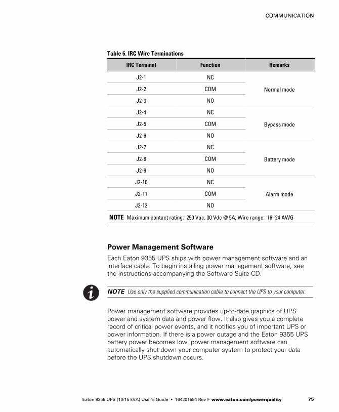
Table 6. IRC Wire Terminations
IRC Terminal Function Remarks
J2-1 NC
Normal modeJ2-2 COM
J2-3 NO
J2-4 NC
Bypass modeJ2-5 COM
J2-6 NO
J2-7 NC
Battery modeJ2-8 COM
J2-9 NO
J2-10 NC
Alarm modeJ2-11 COM
J2-12 NO
NOTE Maximum contact rating: 250 Vac, 30 Vdc @ 5A; Wire range: 16–24 AWG
Power Management Software
Each Eaton 9355 UPS ships with power management software and aninterface cable. To begin installing power management software, seethe instructions accompanying the Software Suite CD.
NOTE Use only the supplied communication cable to connect the UPS to your computer.
Power management software provides up-to-date graphics of UPSpower and system data and power flow. It also gives you a completerecord of critical power events, and it notifies you of important UPS orpower information. If there is a power outage and the Eaton 9355 UPSbattery power becomes low, power management software canautomatically shut down your computer system to protect your databefore the UPS shutdown occurs.
COMMUNICATION
Eaton 9355 UPS (10/15 kVA) User's Guide � 164201594 Rev F www.eaton.com/powerquality76
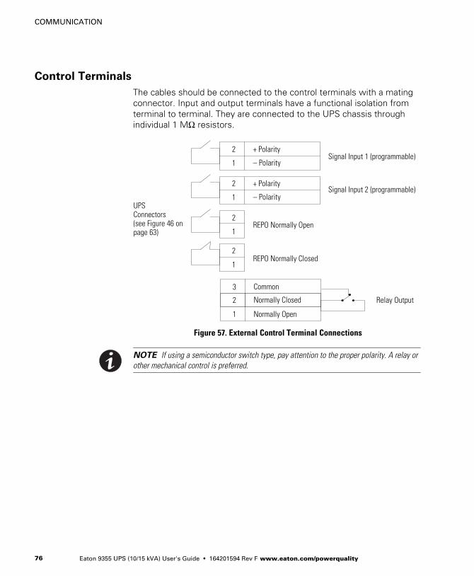
Control Terminals
The cables should be connected to the control terminals with a matingconnector. Input and output terminals have a functional isolation fromterminal to terminal. They are connected to the UPS chassis throughindividual 1 MΩ resistors.
+ Polarity
– Polarity
2
1
+ Polarity
– Polarity
2
1
2
1
2
1
Signal Input 1 (programmable)
Signal Input 2 (programmable)
REPO Normally Open
REPO Normally Closed
Normally Open
Normally Closed
1
2
Common3
Relay Output
UPSConnectors (see Figure 46 onpage 63)
Figure 57. External Control Terminal Connections
NOTE If using a semiconductor switch type, pay attention to the proper polarity. A relay orother mechanical control is preferred.

COMMUNICATION
Eaton 9355 UPS (10/15 kVA) User's Guide � 164201594 Rev F www.eaton.com/powerquality 77
Remote Emergency Power-off
REPO is used to shut down the UPS from a distance. This feature canbe used for shutting down the load and the UPS by thermal relay, forinstance in the event of room overtemperature. When REPO isactivated, the UPS shuts down all converters, de-energizes all systemrelays, trips the battery circuit breaker, and fully powers down within10-15 seconds.
There are two REPO positions that may be used, normally-open ornormally-closed.
The pins on the normally-closed REPO connector are connectedtogether. When this connection is open, the logic circuitry completelyshuts down the UPS, thus preventing the power from supplying theload.
If the use of normally-closed REPO operation is desired, replace theconnector with a normally-closed external switch (see Figure 46 onpage 63).
If the use of normally-open REPO operation is desired, connect anormally-open external switch (see Figure 46 on page 63).
NOTE To restart the UPS, reconnect the REPO connector pins and turn on the UPSmanually. The pins must be shorted to keep the UPS running. Maximum resistance is 10 ohm.
NOTE Leave the REPO connector installed in the REPO port on the UPS rear panel even ifthe REPO function is not needed.
C A U T I O N� The REPO must not be connected to any utility connected circuits. Reinforced insulation
to the utility is required. The REPO switch must have a minimum rating of 24 Vdc and20 mA.
� To ensure the UPS stops supplying power to the load during any mode of operation, theinput power must be disconnected from the UPS when the emergency power-off functionis activated.
REPO Connections
Wire Function Terminal Wire Size Rating Suggested Wire Size
REPO L1 12–22 AWG(4–0.32 mm2)
18 AWG (0.82 mm2)L2
COMMUNICATION
Eaton 9355 UPS (10/15 kVA) User's Guide � 164201594 Rev F www.eaton.com/powerquality78
Relay Output Contacts
The UPS incorporates a programmable relay output with potential freecontacts for remote alarm indications (see Figure 46 on page 63). Anadditional four relay outputs can be obtained with the X-Slot compatibleRelay Interface Card.
W A R N I N GThe relay output contacts must not be connected to any utility connected circuits. Reinforcedinsulation to the utility is required. The relay output contacts must have a maximum rating of30 Vac/1A and 60 Vdc/2A nominal values.
Programmable Signal Inputs
The UPS incorporates two programmable signal inputs (see Figure 46 onpage 63). Use of non-polar (relay) control input is recommended. Thepins must be shorted with maximum resistance of 10 ohm in order toactivate the specific input.
NOTE See Figure 57 on page 76 for the polarity and verify these connections if polaritycontrol is required.
The default and programmable settings for the signal inputs are shownin Table 7.

COMMUNICATION
Eaton 9355 UPS (10/15 kVA) User's Guide � 164201594 Rev F www.eaton.com/powerquality 79
Table 7. Programmable Signal Inputs
Signal Description
Disable Bypass Operation If active, the automatic transfer to the static bypass is prevented.
Charger Off If active, the battery charge function is disabled. In a utility power outage, thedischarge of batteries is supported.
Remote ON/OFF If active, the UPS output turns off regardless of the mode of operation.Auxiliary power, fan, communication, and rectifier/battery charger remainfunctional. Restart is initiated immediately when this signal is inactive.
Request Bypass If active, the UPS transfers to bypass if the bypass voltage, frequency, andsynchronization are all okay.
Request Normal If active, the UPS transfers to inverter operation if not prohibited by REPO or analarm condition.
Force Bypass If active, the UPS is forced to static bypass operation regardless of the bypassstatus.
External Battery Breaker Status If active, the UPS knows that the batteries are disconnected.
Building Alarm 1–6 These alarms can be activated separately or at the same time with otherbuilding alarms.
Not in Use Default
Shutdown If active, the UPS shuts down immediately.
Delayed Shutdown If active, the UPS shuts down after a user-configured delay time. Defaultshutdown delay is 120 seconds. The UPS automatically restarts when thesignal changes to inactive.
Normal/Bypass If active, the UPS transfers to bypass if okay. If inactive, the UPS transfers tothe inverter when possible.
On Generator If active, the UPS knows that input is fed from the generator. Bypass isdisabled; the automatic battery test is disabled.
External TransformerOvertemperature
This option is not used.

COMMUNICATION
Eaton 9355 UPS (10/15 kVA) User's Guide � 164201594 Rev F www.eaton.com/powerquality80

Eaton 9355 UPS (10/15 kVA) User's Guide � 164201594 Rev F www.eaton.com/powerquality 81
Chapter 10 Operation
This chapter contains information on how to use the Eaton 9355 UPS,including front panel operation, UPS startup and shutdown, andconfiguring the UPS for Extended Battery Modules (EBMs).
Control Panel Functions
The UPS has a four-button graphical LCD with backlight. It providesuseful information about the UPS itself, load status, events,measurements, and settings (see Figure 58).
Power On Indicator (green)On Battery Indicator (yellow)
Bypass Indicator (yellow)Alarm Indicator (red)
Control Buttonsfor the LCD Menu Options
Figure 58. Eaton 9355 UPS Control Panel
OPERATION
Eaton 9355 UPS (10/15 kVA) User's Guide � 164201594 Rev F www.eaton.com/powerquality82
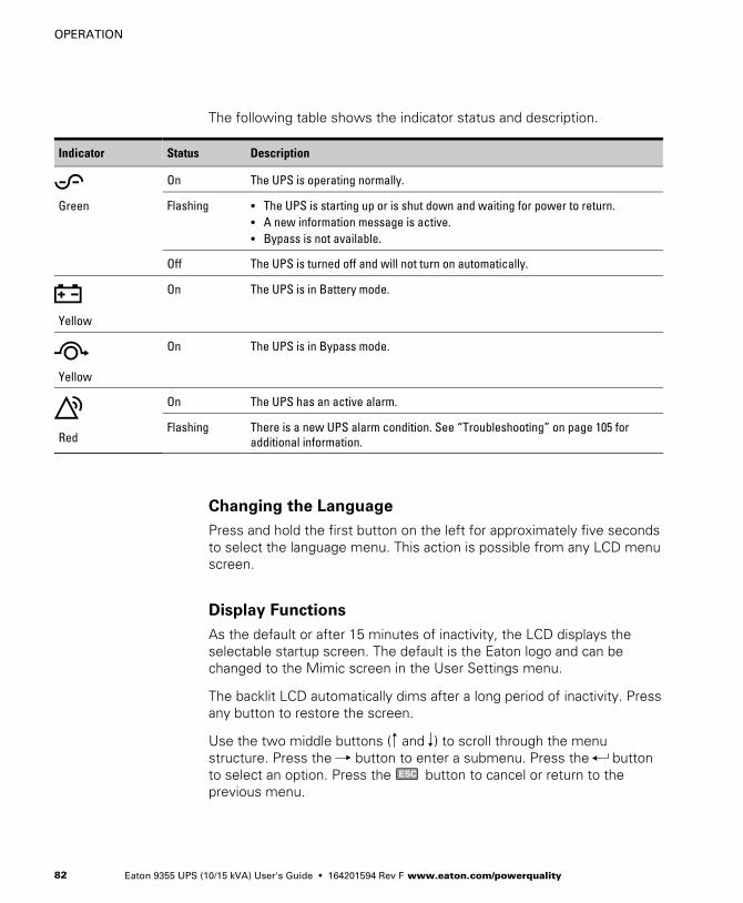
The following table shows the indicator status and description.
Indicator Status Description
Green
On The UPS is operating normally.
Flashing � The UPS is starting up or is shut down and waiting for power to return.� A new information message is active.� Bypass is not available.
Off The UPS is turned off and will not turn on automatically.
Yellow
On The UPS is in Battery mode.
Yellow
On The UPS is in Bypass mode.
Red
On The UPS has an active alarm.
Flashing There is a new UPS alarm condition. See “Troubleshooting” on page 105 foradditional information.
Changing the Language
Press and hold the first button on the left for approximately five secondsto select the language menu. This action is possible from any LCD menuscreen.
Display Functions
As the default or after 15 minutes of inactivity, the LCD displays theselectable startup screen. The default is the Eaton logo and can bechanged to the Mimic screen in the User Settings menu.
The backlit LCD automatically dims after a long period of inactivity. Pressany button to restore the screen.
Use the two middle buttons ( and ) to scroll through the menustructure. Press the button to enter a submenu. Press the buttonto select an option. Press the ESC button to cancel or return to theprevious menu.
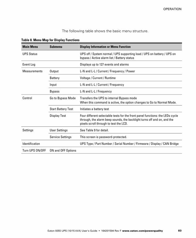
OPERATION
Eaton 9355 UPS (10/15 kVA) User's Guide � 164201594 Rev F www.eaton.com/powerquality 83
The following table shows the basic menu structure.
Table 8. Menu Map for Display Functions
Main Menu Submenu Display Information or Menu Function
UPS Status UPS off / System normal / UPS supporting load / UPS on battery / UPS onbypass / Active alarm list / Battery status
Event Log Displays up to 127 events and alarms
Measurements Output L-N and L-L / Current / Frequency / Power
Battery Voltage / Current / Runtime
Input L-N and L-L / Current / Frequency
Bypass L-N and L-L / Frequency
Control Go to Bypass Mode Transfers the UPS to internal Bypass modeWhen this command is active, the option changes to Go to Normal Mode.
Start Battery Test Initiates a battery test
Display Test Four different selectable tests for the front panel functions: the LEDs cyclethrough, the alarm beep sounds, the backlight turns off and on, and thepixels scroll through to test the LCD.
Settings User Settings See Table 9 for detail.
Service Settings This screen is password-protected.
Identification UPS Type / Part Number / Serial Number / Firmware / Display / CAN Bridge
Turn UPS ON/OFF ON and OFF Options
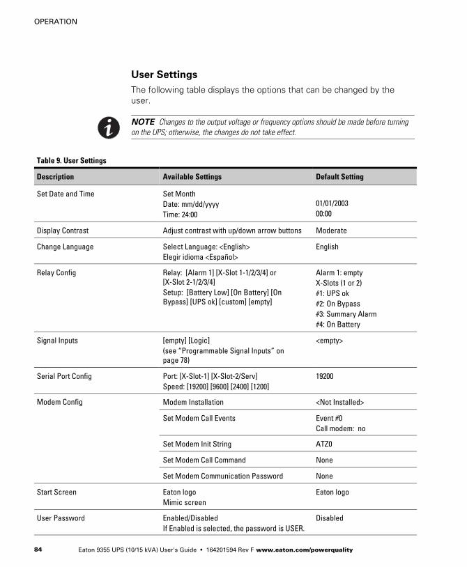
OPERATION
Eaton 9355 UPS (10/15 kVA) User's Guide � 164201594 Rev F www.eaton.com/powerquality84
User Settings
The following table displays the options that can be changed by theuser.
NOTE Changes to the output voltage or frequency options should be made before turningon the UPS; otherwise, the changes do not take effect.
Table 9. User Settings
Description Available Settings Default Setting
Set Date and Time Set MonthDate: mm/dd/yyyyTime: 24:00
01/01/200300:00
Display Contrast Adjust contrast with up/down arrow buttons Moderate
Change Language Select Language: <English>Elegir idioma <Español>
English
Relay Config Relay: [Alarm 1] [X-Slot 1-1/2/3/4] or[X-Slot 2-1/2/3/4]Setup: [Battery Low] [On Battery] [OnBypass] [UPS ok] [custom] [empty]
Alarm 1: emptyX-Slots (1 or 2)#1: UPS ok#2: On Bypass#3: Summary Alarm#4: On Battery
Signal Inputs [empty] [Logic](see “Programmable Signal Inputs” onpage 78)
<empty>
Serial Port Config Port: [X-Slot-1] [X-Slot-2/Serv]Speed: [19200] [9600] [2400] [1200]
19200
Modem Config Modem Installation <Not Installed>
Set Modem Call Events Event #0Call modem: no
Set Modem Init String ATZ0
Set Modem Call Command None
Set Modem Communication Password None
Start Screen Eaton logoMimic screen
Eaton logo
User Password Enabled/DisabledIf Enabled is selected, the password is USER.
Disabled

OPERATION
Eaton 9355 UPS (10/15 kVA) User's Guide � 164201594 Rev F www.eaton.com/powerquality 85
Table 9. User Settings (continued)
Default SettingAvailable SettingsDescription
Audible Alarms Normal Sound/Disabled Normal Sound
Battery Charging ABM cycling/constant ABM cycling
Automatic Battery Tests Enabled/DisabledEnabled automatically runs the battery testonce a month.
Enabled
Full Power Battery Test Enabled/Disabled Enabled
Number of Battery Strings 0 through 22(see “Configuring the UPS for EBMs” onpage 91)
2 strings for UPS-32 models4 strings for UPS-64 models
Battery Capacity 1 through 65535 watts per cell 34 W/cell
Battery Low Alarm Level 1.750 through 1.950 volts per cell 1.880 V/cell
Set Nominal Output Voltage Output:[120V/208V] [127V/220V]
120V/208V
Bypass Voltage High Limit +1 through +20% (1% increments) 120V +10%
Bypass Voltage Low Limit -1 through -20% (1% increments) 120V -15%
Nominal Output Frequency 50 Hz or 60 Hz 60 Hz
Synchronization Enabled/Disabled Enabled
Synchronization Window ±0.5 through ±3.0 Hz(0.1 Hz increments)
±2.0 Hz
Unsynchronized Transfer to Bypass Allowed/Not Allowed Not Allowed
Output Frequency Slew Rate 0.1 though 5 hertz per second(0.1 Hz increments)
0.5 Hz/s
Usage of Bypass Enabled/Disabled Enabled
Transfer to Bypass When Overload After a delay/Immediately After a delay
Automatic Start Delay -1 through 32767 seconds(-1 means disabled)
0s
Control Commands from X-Slot1 Allowed/Disabled Allowed
Control Commands from X-Slot2/Serv Allowed/Disabled Allowed
X-Slot Signal Input Activation Delay 0 through 65 seconds 5s
Input signal delayed shutdown delay 1 through 65535 seconds 120s

OPERATION
Eaton 9355 UPS (10/15 kVA) User's Guide � 164201594 Rev F www.eaton.com/powerquality86
Table 9. User Settings (continued)
Default SettingAvailable SettingsDescription
Site Wiring Fault Notice Enabled/Disabled Enabled
Reset Custom Event Settings 0 through 32 Total: 0/32
Auto Output Configuration Enabled/Disabled Enabled for initial startupDisabled after initial startup
Initial Startup
Startup and operational checks must be performed by an authorizedEaton Customer Service Engineer, or the warranty terms as specified onpage 109 become void. This service is offered as part of the salescontract for the UPS. Contact service in advance (usually a two-weeknotice is required) to reserve a preferred startup date.
UPS Startup
W A R N I N GOnly qualified service personnel (such as a licensed electrician) should perform the UPSinstallation and initial startup. Risk of electrical shock.
Verify that UPS installation has been carried out correctly and the UPSground has been connected.
Select one of the following startup options:
Startup Option Section
Normal mode “Normal Mode Startup” on page 87
Battery mode “Starting the UPS on Battery“ on page 88
Bypass mode “Internal Bypass Startup” on page 89
UPS maintenance bypass “UPS Maintenance Bypass Startup” onpage 90
Wall-mounted maintenance bypass “Wall-Mounted Maintenance BypassStartup” on page 90
Parallel UPS configuration Refer to the Eaton 9355 Parallel UPS(10/15 kVA) User's Guide.

OPERATION
Eaton 9355 UPS (10/15 kVA) User's Guide � 164201594 Rev F www.eaton.com/powerquality 87
Normal Mode Startup
To start up the UPS when the load is de-energized:
1. If an optional wall-mounted bypass cabinet is installed, proceed toStep 2; otherwise, proceed to Step 4.
2. Verify the wall mounted bypass is transferred to UPS mode (see“Using the Wall-Mounted Bypass Cabinet” on page 97.
3. Proceed to Step 4.
4. Verify that the internal maintenance bypass switch is in the UPSposition (see Figure 59 on page 95).
5. If an optional isolation transformer is installed, switch the inputcircuit breaker to the ON position (see Figure 12 on page 21).
6. Switch on utility power where the UPS is connected.
7. Wait for the front panel LCD to illuminate.
The indicator flashes.
8. Remove the breaker tie from all battery circuit breakers.
9. Switch all battery circuit breakers to the ON position.
The indicator stops flashing.
10. Press any button on the front panel display to activate the menuoptions.
11. Press the button on the front panel display and then press the button to select the TURN UPS ON/OFF menu.
12. Select the TURN UPS ON option. Press and hold the button forthree seconds, until the UPS stops beeping.
The indicator illuminates. The UPS is now powering the load.
If the indicator is flashing, check the UPS status from the frontpanel to view the active alarms. Correct the alarms and restart ifnecessary.
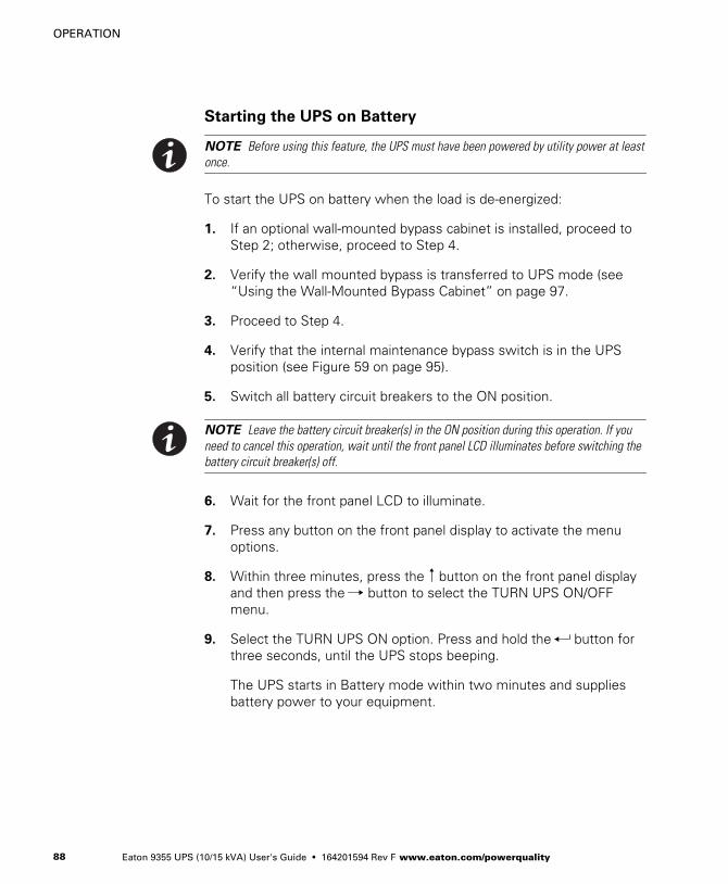
OPERATION
Eaton 9355 UPS (10/15 kVA) User's Guide � 164201594 Rev F www.eaton.com/powerquality88
Starting the UPS on Battery
NOTE Before using this feature, the UPS must have been powered by utility power at leastonce.
To start the UPS on battery when the load is de-energized:
1. If an optional wall-mounted bypass cabinet is installed, proceed toStep 2; otherwise, proceed to Step 4.
2. Verify the wall mounted bypass is transferred to UPS mode (see“Using the Wall-Mounted Bypass Cabinet” on page 97.
3. Proceed to Step 4.
4. Verify that the internal maintenance bypass switch is in the UPSposition (see Figure 59 on page 95).
5. Switch all battery circuit breakers to the ON position.
NOTE Leave the battery circuit breaker(s) in the ON position during this operation. If youneed to cancel this operation, wait until the front panel LCD illuminates before switching thebattery circuit breaker(s) off.
6. Wait for the front panel LCD to illuminate.
7. Press any button on the front panel display to activate the menuoptions.
8. Within three minutes, press the button on the front panel displayand then press the button to select the TURN UPS ON/OFFmenu.
9. Select the TURN UPS ON option. Press and hold the button forthree seconds, until the UPS stops beeping.
The UPS starts in Battery mode within two minutes and suppliesbattery power to your equipment.
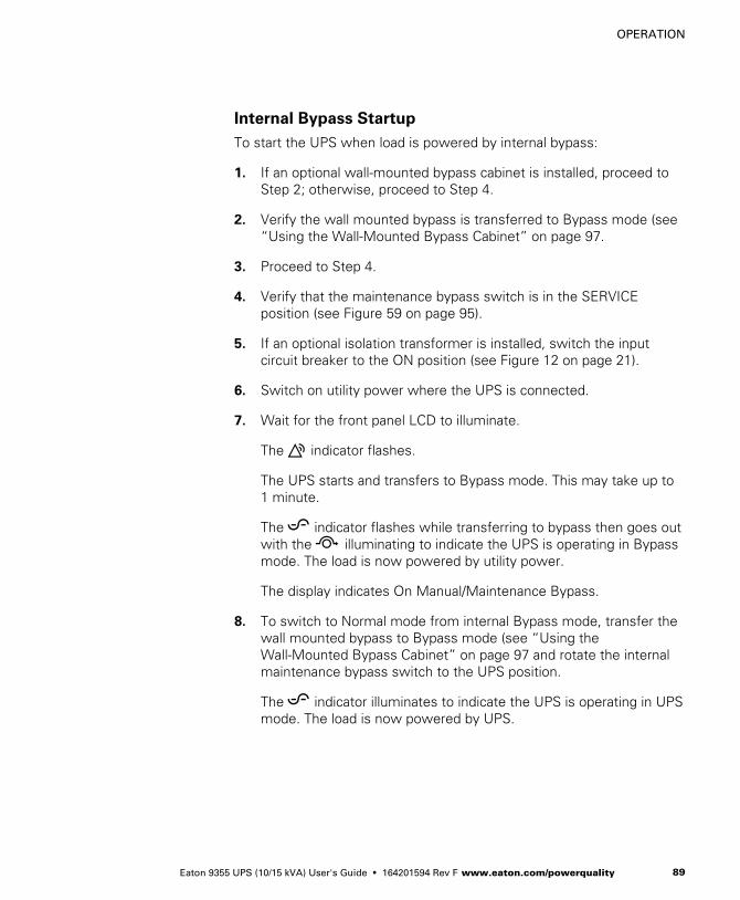
OPERATION
Eaton 9355 UPS (10/15 kVA) User's Guide � 164201594 Rev F www.eaton.com/powerquality 89
Internal Bypass Startup
To start the UPS when load is powered by internal bypass:
1. If an optional wall-mounted bypass cabinet is installed, proceed toStep 2; otherwise, proceed to Step 4.
2. Verify the wall mounted bypass is transferred to Bypass mode (see“Using the Wall-Mounted Bypass Cabinet” on page 97.
3. Proceed to Step 4.
4. Verify that the maintenance bypass switch is in the SERVICEposition (see Figure 59 on page 95).
5. If an optional isolation transformer is installed, switch the inputcircuit breaker to the ON position (see Figure 12 on page 21).
6. Switch on utility power where the UPS is connected.
7. Wait for the front panel LCD to illuminate.
The indicator flashes.
The UPS starts and transfers to Bypass mode. This may take up to1 minute.
The indicator flashes while transferring to bypass then goes outwith the illuminating to indicate the UPS is operating in Bypassmode. The load is now powered by utility power.
The display indicates On Manual/Maintenance Bypass.
8. To switch to Normal mode from internal Bypass mode, transfer thewall mounted bypass to Bypass mode (see “Using theWall-Mounted Bypass Cabinet” on page 97 and rotate the internalmaintenance bypass switch to the UPS position.
The indicator illuminates to indicate the UPS is operating in UPSmode. The load is now powered by UPS.
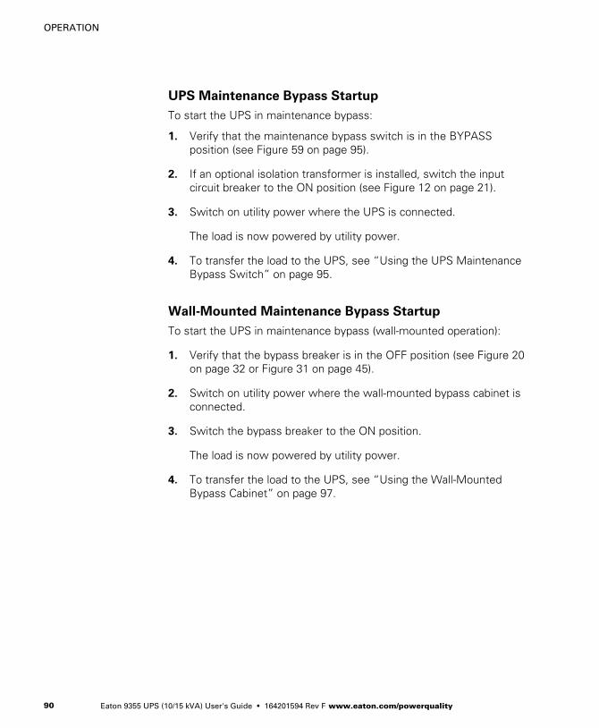
OPERATION
Eaton 9355 UPS (10/15 kVA) User's Guide � 164201594 Rev F www.eaton.com/powerquality90
UPS Maintenance Bypass Startup
To start the UPS in maintenance bypass:
1. Verify that the maintenance bypass switch is in the BYPASSposition (see Figure 59 on page 95).
2. If an optional isolation transformer is installed, switch the inputcircuit breaker to the ON position (see Figure 12 on page 21).
3. Switch on utility power where the UPS is connected.
The load is now powered by utility power.
4. To transfer the load to the UPS, see “Using the UPS MaintenanceBypass Switch” on page 95.
Wall-Mounted Maintenance Bypass Startup
To start the UPS in maintenance bypass (wall-mounted operation):
1. Verify that the bypass breaker is in the OFF position (see Figure 20on page 32 or Figure 31 on page 45).
2. Switch on utility power where the wall-mounted bypass cabinet isconnected.
3. Switch the bypass breaker to the ON position.
The load is now powered by utility power.
4. To transfer the load to the UPS, see “Using the Wall-MountedBypass Cabinet” on page 97.

OPERATION
Eaton 9355 UPS (10/15 kVA) User's Guide � 164201594 Rev F www.eaton.com/powerquality 91
Configuring the UPS for EBMs
To ensure maximum battery runtime, configure the UPS for the correctnumber of EBMs:
1. Press any button on the front panel display to activate the menuoptions.
2. Using the button, scroll to the Settings menu.
3. Press the button twice to select the User Settings menu.
4. Using the button, scroll to the Number of Battery Strings optionand press the button.
5. Use the or buttons to select the number of strings according toyour UPS configuration:
All 2-High UPS and EBM Cabinets* Number of Strings
UPS + 1 EBM 6
UPS + 2 EBMs 10
UPS + 3 EBMs 14
UPS + 4 EBMs 18
All 3-High UPS and EBM Cabinets* Number of Strings
UPS + 1 EBM 10
UPS + 2 EBMs 16
UPS + 3 EBMs 22
* UPS-32 models contain 2 strings; EBM-64 models contain 4 strings.UPS-64 models contain 4 strings; EBM-96 models contain 6 strings.
6. Press the button to save the setting.
7. Press the ESC button until the Eaton logo appears.
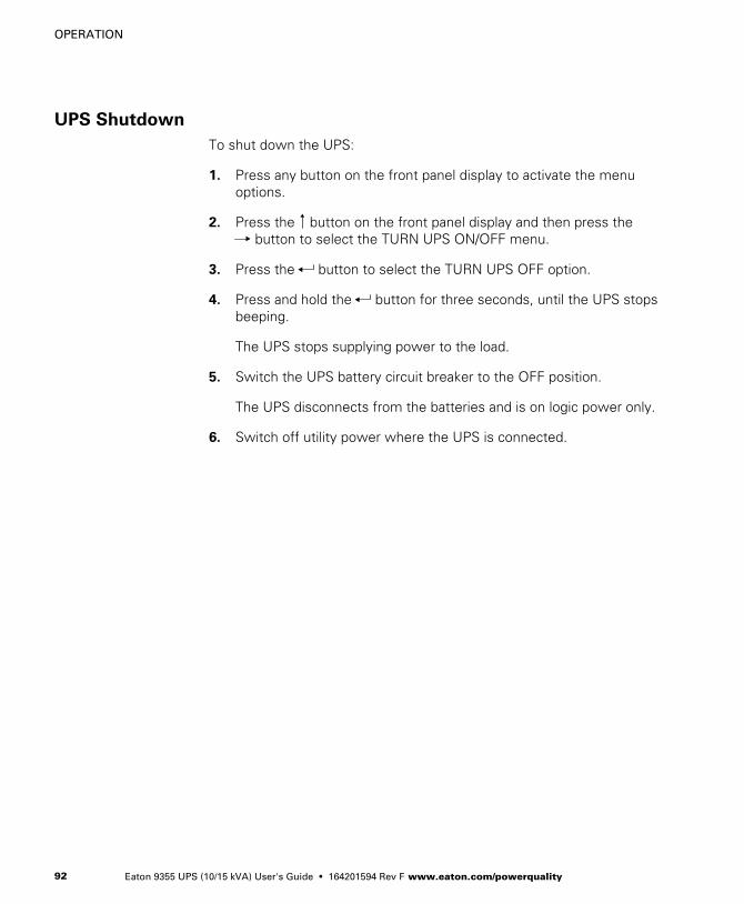
OPERATION
Eaton 9355 UPS (10/15 kVA) User's Guide � 164201594 Rev F www.eaton.com/powerquality92
UPS Shutdown
To shut down the UPS:
1. Press any button on the front panel display to activate the menuoptions.
2. Press the button on the front panel display and then press the button to select the TURN UPS ON/OFF menu.
3. Press the button to select the TURN UPS OFF option.
4. Press and hold the button for three seconds, until the UPS stopsbeeping.
The UPS stops supplying power to the load.
5. Switch the UPS battery circuit breaker to the OFF position.
The UPS disconnects from the batteries and is on logic power only.
6. Switch off utility power where the UPS is connected.

Eaton 9355 UPS (10/15 kVA) User's Guide � 164201594 Rev F www.eaton.com/powerquality 93
Chapter 11 UPS Maintenance
This section explains how to:
� Care for the UPS and batteries
� Recycle used batteries or UPS
� Use the maintenance bypass switch
UPS and Battery Care
For the best preventive maintenance, keep the area around the UPSclean and dust‐free. If the atmosphere is very dusty, clean the outside ofthe system with a vacuum cleaner.
For full battery life, keep the UPS at an ambient temperature of77°F (25°C).
NOTE The batteries in the UPS are rated for a 3–5 year service life. The length ofservice life varies, depending on the frequency of usage and ambient temperature.Batteries used beyond expected service life will often have severely reduced runtimes.Replace batteries at least every 5 years to keep units running at peak efficiency.
Storing the UPS and Batteries
When storing the UPS and optional cabinets, the following requirementsshould be met:
� Verify that the battery circuit breaker is in the OFF position.
� Avoid temperature and humidity extremes. To maximize battery life,the recommended storage temperature is 59°F (15°C) to 77°F (25°C).
� If you store the UPS for a long period, recharge the batteries every10 months by applying utility power. The batteries charge to 80%capacity in approximately 3 hours. However, it is recommended thatthe batteries charge for 48 hours after long-term storage.
� Check the battery recharge date on the shipping carton label. If thedate has expired and the batteries were never recharged, do not usethe UPS. Contact your service representative.

UPS MAINTENANCE
Eaton 9355 UPS (10/15 kVA) User's Guide � 164201594 Rev F www.eaton.com/powerquality94
When to Replace Batteries
When the indicator flashes and the LCD panel displays BatteryFailure, the batteries may need replacing. Contact your servicerepresentative to order new batteries.
Change the batteries approximately every five years.
Recycling the Used Battery or UPS
Contact your local recycling or hazardous waste center for informationon proper disposal of the used battery or UPS.
W A R N I N G� Do not dispose of the battery or batteries in a fire. Batteries may explode. Proper
disposal of batteries is required. Refer to your local codes for disposal requirements.
� Do not open or mutilate the battery or batteries. Released electrolyte is harmful to theskin and eyes. It may be toxic.
C A U T I O NDo not discard the UPS or the UPS batteries in the trash. This product contains sealed,lead‐acid batteries and must be disposed of properly. For more information, contact yourlocal recycling/reuse or hazardous waste center.
C A U T I O NDo not discard waste electrical or electronic equipment (WEEE) in the trash. For properdisposal, contact your local recycling/reuse or hazardous waste center.

UPS MAINTENANCE
Eaton 9355 UPS (10/15 kVA) User's Guide � 164201594 Rev F www.eaton.com/powerquality 95
Using the UPS Maintenance Bypass Switch
The UPS maintenance bypass switch is located on the back of the UPS(see Figure 59).
The maintenance bypass switch is used to bypass the UPS duringmaintenance or servicing. The switch provides a wrap-around bypasswithout shutting down the load. The SERVICE position on the switchallows a service engineer to apply power to the UPS input and verify itsoperation while the load is powered through bypass.
Figure 59. Maintenance Bypass Switch
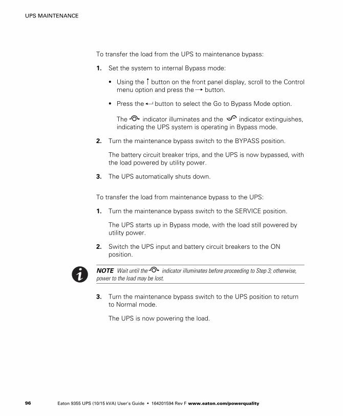
UPS MAINTENANCE
Eaton 9355 UPS (10/15 kVA) User's Guide � 164201594 Rev F www.eaton.com/powerquality96
To transfer the load from the UPS to maintenance bypass:
1. Set the system to internal Bypass mode:
� Using the button on the front panel display, scroll to the Controlmenu option and press the button.
� Press the button to select the Go to Bypass Mode option.
The indicator illuminates and the indicator extinguishes,indicating the UPS system is operating in Bypass mode.
2. Turn the maintenance bypass switch to the BYPASS position.
The battery circuit breaker trips, and the UPS is now bypassed, withthe load powered by utility power.
3. The UPS automatically shuts down.
To transfer the load from maintenance bypass to the UPS:
1. Turn the maintenance bypass switch to the SERVICE position.
The UPS starts up in Bypass mode, with the load still powered byutility power.
2. Switch the UPS input and battery circuit breakers to the ONposition.
NOTE Wait until the indicator illuminates before proceeding to Step 3; otherwise,power to the load may be lost.
3. Turn the maintenance bypass switch to the UPS position to returnto Normal mode.
The UPS is now powering the load.
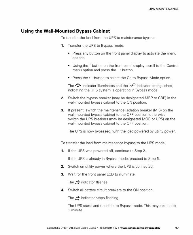
UPS MAINTENANCE
Eaton 9355 UPS (10/15 kVA) User's Guide � 164201594 Rev F www.eaton.com/powerquality 97
Using the Wall-Mounted Bypass Cabinet
To transfer the load from the UPS to maintenance bypass:
1. Transfer the UPS to Bypass mode:
� Press any button on the front panel display to activate the menuoptions.
� Using the button on the front panel display, scroll to the Controlmenu option and press the button.
� Press the button to select the Go to Bypass Mode option.
The indicator illuminates and the indicator extinguishes,indicating the UPS system is operating in Bypass mode.
2. Switch the bypass breaker (may be designated MBP or CBP) in thewall-mounted bypass cabinet to the ON position.
3. If present, switch the maintenance isolation breaker (MIS) on thewall-mounted bypass cabinet to the OFF position; otherwise,switch the UPS breakers (may be designated MOB or UPS) on thewall-mounted bypass cabinet to the OFF position.
The UPS is now bypassed, with the load powered by utility power.
To transfer the load from maintenance bypass to the UPS mode:
1. If the UPS was powered off, continue to Step 2.
If the UPS is already in Bypass mode, proceed to Step 6.
2. Switch on utility power where the UPS is connected.
3. Wait for the front panel LCD to illuminate.
The indicator flashes.
4. Switch all battery circuit breakers to the ON position.
The indicator stops flashing.
The UPS starts and transfers to Bypass mode. This may take up to1 minute.
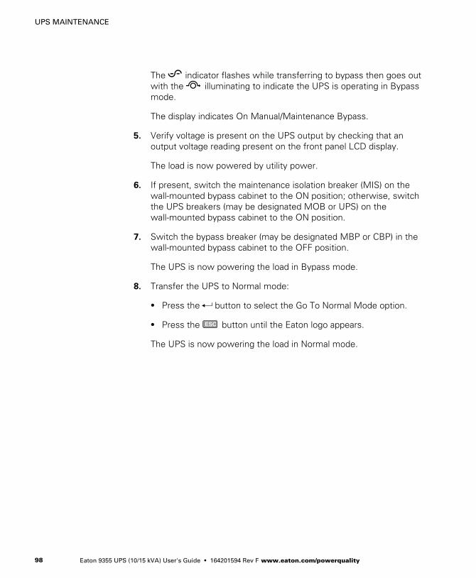
UPS MAINTENANCE
Eaton 9355 UPS (10/15 kVA) User's Guide � 164201594 Rev F www.eaton.com/powerquality98
The indicator flashes while transferring to bypass then goes outwith the illuminating to indicate the UPS is operating in Bypassmode.
The display indicates On Manual/Maintenance Bypass.
5. Verify voltage is present on the UPS output by checking that anoutput voltage reading present on the front panel LCD display.
The load is now powered by utility power.
6. If present, switch the maintenance isolation breaker (MIS) on thewall-mounted bypass cabinet to the ON position; otherwise, switchthe UPS breakers (may be designated MOB or UPS) on thewall-mounted bypass cabinet to the ON position.
7. Switch the bypass breaker (may be designated MBP or CBP) in thewall-mounted bypass cabinet to the OFF position.
The UPS is now powering the load in Bypass mode.
8. Transfer the UPS to Normal mode:
� Press the button to select the Go To Normal Mode option.
� Press the ESC button until the Eaton logo appears.
The UPS is now powering the load in Normal mode.
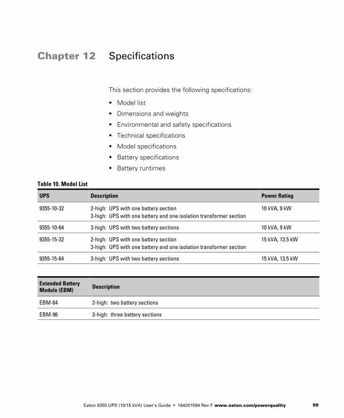
Eaton 9355 UPS (10/15 kVA) User's Guide � 164201594 Rev F www.eaton.com/powerquality 99
Chapter 12 Specifications
This section provides the following specifications:
� Model list
� Dimensions and weights
� Environmental and safety specifications
� Technical specifications
� Model specifications
� Battery specifications
� Battery runtimes
Table 10. Model List
UPS Description Power Rating
9355-10-32 2-high: UPS with one battery section3-high: UPS with one battery and one isolation transformer section
10 kVA, 9 kW
9355-10-64 3-high: UPS with two battery sections 10 kVA, 9 kW
9355-15-32 2-high: UPS with one battery section3-high: UPS with one battery and one isolation transformer section
15 kVA, 13.5 kW
9355-15-64 3-high: UPS with two battery sections 15 kVA, 13.5 kW
Extended BatteryModule (EBM) Description
EBM-64 2-high: two battery sections
EBM-96 3-high: three battery sections
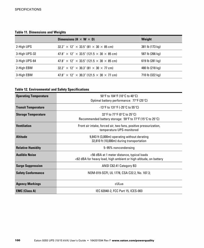
SPECIFICATIONS
Eaton 9355 UPS (10/15 kVA) User's Guide � 164201594 Rev F www.eaton.com/powerquality100
Table 11. Dimensions and Weights
Dimensions (H � W � D) Weight
2-High UPS 32.2” � 12” � 33.5” (81 � 30 � 85 cm) 381 lb (173 kg)
3-High UPS-32 47.8” � 12” � 33.5” (121.5 � 30 � 85 cm) 587 lb (266 kg)
3-High UPS-64 47.8” � 12” � 33.5” (121.5 � 30 � 85 cm) 619 lb (281 kg)
2-High EBM 32.2” � 12” � 30.3” (81 � 30 � 77 cm) 480 lb (218 kg)
3-High EBM 47.8” � 12” � 30.3” (121.5 � 30 � 77 cm) 710 lb (322 kg)
Table 12. Environmental and Safety Specifications
Operating Temperature 50°F to 104°F (10°C to 40°C)Optimal battery performance: 77°F (25°C)
Transit Temperature -13°F to 131°F (-25°C to 55°C)
Storage Temperature 32°F to 77°F (0°C to 25°C)Recommended battery storage: 59°F to 77°F (15°C to 25°C)
Ventilation Front air intake, forced air, two fans, positive pressurization,temperature UPS-monitored
Altitude 9,843 ft (3,000m) operating without derating32,810 ft (10,000m) during transportation
Relative Humidity 5–95% noncondensing
Audible Noise <56 dBA at 1 meter distance, typical loads<62 dBA for heavy load, high ambient or high altitude, on battery
Surge Suppression ANSI C62.41 Category B3
Safety Conformance NOM-019-SCFI, UL 1778, CSA C22.2, No. 107.3;
Agency Markings cULus
EMC (Class A) IEC 62040-2, FCC Part 15, ICES-003

SPECIFICATIONS
Eaton 9355 UPS (10/15 kVA) User's Guide � 164201594 Rev F www.eaton.com/powerquality 101
Table 13. Technical Specifications
Technology Online, double‐conversion topology with static bypass switch and 3‐position maintenance bypass switch.
Frequency independent operation.
Input Voltage Range 75/130–144/249 Vac per phase
Input Power Factor >0.99 at full load nominal line conditions
Input Rated Voltage 120/208 or 127/220 Vac three-phase
Isolation Transformer InputVoltage Range
480V or 600V ±20%60 Hz only
Input Frequency Range 45–65 Hz
Input Rated Frequency 50/60-Hz selectable, auto‐configuring
Output Voltage Regulation ±1% static, Phase to Neutral±2% static, Phase to Phase
±5% dynamic at 100% resistive load changeResponse time <1 ms
Output Voltage Distortion <2% THD linear load<5% THD non‐linear load
Output Frequency 50/60-Hz selectable or auto‐configuring
Output FrequencyRegulation
Synchronization to line
Output Overload 101–110% for 10 minutes111–125% for 60 seconds126–149% for 5 seconds
>150% for 300 milliseconds

SPECIFICATIONS
Eaton 9355 UPS (10/15 kVA) User's Guide � 164201594 Rev F www.eaton.com/powerquality102
Table 14. Model Specifications
10 kVA Model
Output Voltage (Line–Line) 208 208 208 220
Output Voltage (Line–Neutral) 120 120 120 127
Input Voltage 208 480 (with inputisolation
transformer)
600V (with inputisolation
transformer)
220
Input Current 32.2A 16A 13.3A 30.5A
Output Current 27.8A 27.8A 27.8A 26.2A
Output kVA 10 10 10 10
Output kW 9 9 9 9
Efficiency (Minimum) 89% 83% 83% 89%
Heat Rejection [BTU/hr (kg-cal/hr)] 3798 (956) 6294 (1585) 6294 (1585) 3798 (956)
15 kVA Model
Output Voltage (Line–Line) 208 208 208 220
Output Voltage (Line–Neutral) 120 120 120 127
Input Voltage 208 480 (with inputisolation
transformer)
600 (with inputisolation
transformer)
220
Input Current 48A 24A 20A 45.7A
Output Current 41.6A 41.6A 41.6A 39.4A
Output kVA 15 15 15 15
Output kW 13.5 13.5 13.5 13.5
Efficiency (Minimum) 90% 85% 85% 90%
Heat Rejection [BTU/hr (kg-cal/hr)] 5122 (1290) 8134 (2048) 8134 (2048) 5122 (1290)

SPECIFICATIONS
Eaton 9355 UPS (10/15 kVA) User's Guide � 164201594 Rev F www.eaton.com/powerquality 103
Table 15. Battery Specifications
Battery Type 9 Ah sealed, valve-regulated lead acid (VRLA), maintenance-free, minimum 3-year floatservice life at 25°C (77°F), voltage 192 Vdc (96 cells per string)
Number of Strings Maximum of 22 strings per full configuration, including UPS batteries (4 EBM-64 cabinets or 3 EBM-96 cabinets, plus UPS batteries)
UPS-32: 2 strings; UPS-64: 4 stringsEBM-64: 4 strings; EBM-96: 6 strings
Battery Replacement Must be replaced by a qualified service technician
Charger Service configurable 0.5–34A per string, with overall maximum of 34A (limited by inputcurrent). Default: 3.4A per string
Charging Internal battery: approximately 3 hours to 80% usable capacity at nominal line voltageafter full load discharge
External battery: no more than 10x discharge time to 90% usable capacity at nominal linevoltage after full load discharge
Start-on-Battery Allows start of UPS without utility input
Performance ABM technology increases battery service life, optimizes recharge time, and provides awarning before the end of useful battery life
Protection Extended Battery Module output protected by 100A circuit breaker
Table 16. Battery Runtimes (in Minutes) at Full Load
2-High Cabinets
Load 32 Internal UPSBatteries (1) EBM-64 (2) EBM-64 (3) EBM-64 (4) EBM-64
15 kVA/13.5 kW 4 23 43 65 88
10 kVA/9 kW 8 37 69 106 144
3-High Cabinets
Load 64 Internal UPSBatteries (1) EBM-96 (2) EBM-96 (3) EBM-96
15 kVA/13.5 kW 13 43 76 113
10 kVA/9 kW 22 69 124 184
NOTE Battery times are approximate and vary depending on the load configuration and battery charge.

SPECIFICATIONS
Eaton 9355 UPS (10/15 kVA) User's Guide � 164201594 Rev F www.eaton.com/powerquality104
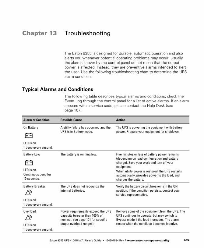
Eaton 9355 UPS (10/15 kVA) User's Guide � 164201594 Rev F www.eaton.com/powerquality 105
Chapter 13 Troubleshooting
The Eaton 9355 is designed for durable, automatic operation and alsoalerts you whenever potential operating problems may occur. Usuallythe alarms shown by the control panel do not mean that the outputpower is affected. Instead, they are preventive alarms intended to alertthe user. Use the following troubleshooting chart to determine the UPSalarm condition.
Typical Alarms and Conditions
The following table describes typical alarms and conditions; check theEvent Log through the control panel for a list of active alarms. If an alarmappears with a service code, please contact the Help Desk (seepage 107).
Alarm or Condition Possible Cause Action
On Battery
LED is on.1 beep every second.
A utility failure has occurred and theUPS is in Battery mode.
The UPS is powering the equipment with batterypower. Prepare your equipment for shutdown.
Battery Low
LED is on.Continuous beep for10 seconds.
The battery is running low. Five minutes or less of battery power remains(depending on load configuration and batterycharge). Save your work and turn off yourequipment.When utility power is restored, the UPS restartsautomatically, provides power to the load, andcharges the battery.
Battery Breaker
LED is on.1 beep every second.
The UPS does not recognize theinternal batteries.
Verify the battery circuit breaker is in the ONposition. If the condition persists, contact yourservice representative.
Overload
LED is on.1 beep every second.
Power requirements exceed the UPScapacity (greater than 100% ofnominal; see page 101 for specificoutput overload ranges).
Remove some of the equipment from the UPS. TheUPS continues to operate, but may switch toBypass mode if the load increases. The alarmresets when the condition becomes inactive.
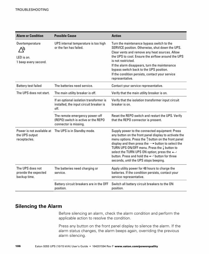
TROUBLESHOOTING
Eaton 9355 UPS (10/15 kVA) User's Guide � 164201594 Rev F www.eaton.com/powerquality106
ActionPossible CauseAlarm or Condition
Overtemperature
LED is on.1 beep every second.
UPS internal temperature is too highor the fan has failed.
Turn the maintenance bypass switch to theSERVICE position. Otherwise, shut down the UPS.Clear vents and remove any heat sources. Allowthe UPS to cool. Ensure the airflow around the UPSis not restricted.If the alarm disappears, turn the maintenancebypass switch back to the UPS position.If the condition persists, contact your servicerepresentative.
Battery test failed The batteries need service. Contact your service representative.
The UPS does not start. The main utility breaker is off. Verify that the main utility breaker is on.
If an optional isolation transformer isinstalled, the input circuit breaker isoff.
Verify that the isolation transformer input circuitbreaker is on.
The remote emergency power-off(REPO) switch is active or the REPOconnector is missing.
Reset the REPO switch and restart the UPS. Verifythat the REPO connector is present.
Power is not available atthe UPS outputreceptacles.
The UPS is in Standby mode. Supply power to the connected equipment: Pressany button on the front panel display to activate themenu options. Press the button on the front paneldisplay and then press the button to select theTURN UPS ON/OFF menu. Press the button toselect the TURN UPS ON option; press thebutton. Press and hold the button for threeseconds, until the UPS stops beeping.
The UPS does notprovide the expectedbackup time.
The batteries need charging orservice.
Apply utility power for 48 hours to charge thebatteries. If the condition persists, contact yourservice representative.
Battery circuit breakers are in the OFFposition.
Switch all battery circuit breakers to the ONposition.
Silencing the Alarm
Before silencing an alarm, check the alarm condition and perform theapplicable action to resolve the condition.
Press any button on the front panel display to silence the alarm. If thealarm status changes, the alarm beeps again, overriding the previousalarm silencing.
TROUBLESHOOTING
Eaton 9355 UPS (10/15 kVA) User's Guide � 164201594 Rev F www.eaton.com/powerquality 107
Service and Support
If you have any questions or problems with the UPS, call your LocalDistributor or the Help Desk at one of the following telephone numbersand ask for a UPS technical representative.
United States: 1-800-843-9433Canada: 1-800-461-9166 ext 260All other countries: Call your local service representative
Please have the following information ready when you call for service:
� Model number
� Serial number
� Firmware version number
� Date of failure or problem
� Symptoms of failure or problem
� Customer return address and contact information

TROUBLESHOOTING
Eaton 9355 UPS (10/15 kVA) User's Guide � 164201594 Rev F www.eaton.com/powerquality108

Eaton 9355 UPS (10/15 kVA) User's Guide � 164201594 Rev F www.eaton.com/powerquality 109
Chapter 14 Warranty
Limited Factory Warranty
Eaton 9355 UPS Products
WARRANTOR: The warrantor for the limited warranties set forth herein is Eaton (“Eaton”).
LIMITED WARRANTY: This limited warranty (this “Warranty”) applies only to the original end-user (the “End-User”)of the Eaton 9355 UPS Products (the “Product”) and cannot be transferred. This Warranty applies even in the eventthat the Product is initially sold by Eaton for resale to an End-User.
WHAT THIS LIMITED WARRANTY COVERS: The warrantor warrants,with the terms of this Warranty, that the Eatonthree-phase UPS electronics, Eaton-built accessories, and Eaton -built battery cabinets (individually and collectively,the ”Warranted Items”) are free from defects in material and workmanship.
For Product installed (and currently located) in the fifty (50) United States and the District of Columbia, if, in theopinion of Eaton, a Warranted Item is defective, Eaton's sole obligation, at the option of Eaton, will be to refurbish orreplace such defective Warranted Item (including the costs of providing diagnosis, service, and labor [“laborcoverage”]). The defective Warranted Item will be refurbished or replaced onsite at the End-User's location or suchother location as determined by Eaton. Any parts that are replaced may be new or reconditioned. All parts replacedby Eaton shall become the property of Eaton.
For Product installed (and currently located) outside the fifty (50) United States and the District of Columbia, if, in theopinion of Eaton, a Warranted Item is defective, Eaton's sole obligation, at the option of Eaton, will be to refurbish orreplace such defective Warranted Item (not including the costs of labor coverage). The defective Warranted Itemwill be refurbished or replaced onsite at the End-User's location or such other location as determined by Eaton. Anyparts that are replaced may be new or reconditioned. All parts replaced by Eaton shall become the property ofEaton.
LIMITED WARRANTY PERIOD: The period covered by this Warranty for Product installed (and currently located) in the fifty (50) United States andthe District of Columbia is ninety (90) days from the date of Product purchase for labor coverage and twelve (12)months from the date of Product purchase or eighteen (18) months from the date of Product shipment, whicheveroccurs first, for the refurbishment/replacement of parts.
The period covered by this Warranty for Product installed (and currently located) outside the fifty (50) United Statesand the District of Columbia is ninety twelve (12) months from the date of Product purchase or eighteen (18)months from the date of Product shipment, whichever occurs first, for the refurbishment/replacement of parts.
WHAT THIS LIMITED WARRANTY DOES NOT COVER: This Warranty does not cover any defects or damagescaused by: (a) failure to properly store the Product before installation, including the ”trickle charge” of batteries nolater than the date indicated on the packaging; (b) shipping and delivery of the Product if shipping is FOB Factory;(c) neglect, accident, fire, flood, lightning, vandalism, acts of God, Customer's neglect, abuse, misuse,misapplication, incorrect installation; (d) repair or alteration not authorized in writing by Eaton personnel orperformed by an authorized Eaton Customer Service Engineer or Agent; or (e) improper testing, operation,maintenance, adjustment, or any modification of any kind not authorized in writing by Eaton personnel or performedby an authorized Eaton Customer Service Engineer or Agent.
WARRANTY
Eaton 9355 UPS (10/15 kVA) User's Guide � 164201594 Rev F www.eaton.com/powerquality110
This Warranty is not valid: if the Product's serial numbers have been removed or are illegible. Any Warranted Itemsrepaired or replaced pursuant to this Warranty will be warranted for the remaining portion of the original Warrantysubject to all the terms thereof. Labor warranty is not provided for Product located outside of the fifty (50) UnitedStates or the District of Columbia. Any equipment, parts, or materials included in the Product and notmanufactured by Eaton are warranted solely by the manufacturer of such equipment, parts, or materials and arenot included as part of this Warranty. Batteries are not warranted by Eaton.
THIS WARRANTY IS THE END-USER'S SOLE REMEDY AND IS EXPRESSLY IN LIEU OF, AND THERE ARE NO OTHEREXPRESSED OR IMPLIED GUARANTEES OR WARRANTIES (INCLUDING ANY IMPLIED WARRANTY OFMERCHANTABILITY OR FITNESS FOR ANY PURPOSE, WHICH ARE EXPRESSLY DISCLAIMED).
LIMITATION OF LIABILITY: In no event shall Eaton be liable for any indirect, incidental, special, or consequentialdamages of any kind or type whatsoever, or based on any claim or cause of action, however denominated. Eatonshall not be responsible for failure to provide service or parts due to causes beyond Eaton's reasonable control. Inno case will Eaton's liability under this Warranty exceed the replacement value of the Warranted Items.
END-USER'S OBLIGATIONS: In order to receive the benefits of this Warranty, the End-User must register theproduct warranty (via mail or online at www.eaton.com/PQ/Register); use the Product in a normal way; follow theProduct's user's guide; and protect against further damage to the Product if there is a covered defect.
OTHER LIMITATIONS: Eaton's obligations under this Warranty are expressly conditioned upon receipt by Eaton ofall payments due to it (including interest charges, if any). During such time as Eaton has not received payment ofany amount due to it for the Product, in accordance with the contract terms under which the Product is sold, Eatonshall have no obligation under this Warranty. Also during such time, the period of this Warranty shall continue to runand the expiration of this Warranty shall not be extended upon payment of any overdue or unpaid amounts.
COSTS NOT RELATED TO WARRANTY: The End-User shall be invoiced for, and shall pay for, all services notexpressly provided for by the terms of this Warranty, including without limitation site calls involving an inspectionthat determines no corrective maintenance is required. Any costs for replacement equipment, installation, materials,freight charges, travel expenses, or labor of Eaton representatives outside the terms of this Warranty will be borneby the End-User.
OBTAINING WARRANTY SERVICE: In the USA, call the Eaton Customer Reliability Center 7x24 at 800-843-9433.Outside of the USA, call your local Eaton sales or service representative. For comments or questions about thisWarranty, write to the Customer Quality Representative, 8609 Six Forks Road, Raleigh, North Carolina 27615 USA.


![Journal J. Am. Ceram. Soc., 82 [4] 873–81 (1999)](https://img.pdfslide.us/doc/110x75/6169f81211a7b741a34d5ffb/journal-j-am-ceram-soc-82-4-87381-1999.jpg)