Embed Size (px)
Citation preview

IMPORTANT SAFETY INSTRUCTIONSREAD AND FOLLOW ALL INSTRUCTIONSSAVE THESE INSTRUCTIONS
EasyTouch® 8 and 4Indoor Control Panel
Installation andUser’s Guide

© 2005 Pentair Water Pool and Spa, Inc. All rights reserved
This document is subject to change without notice
1620 Hawkins Ave., Sanford, NC 27330 • (919) 566-800010951 West Los Angeles Ave., Moorpark, CA 93021 • (805) 553-5000
Trademarks and disclaimers: EasyTouch, IntelliChlor, IntelliFlo, QuickTouch and the Pentair Water Pool and Spalogo are trademarks of Pentair Water Pool and Spa, Inc. Other trademarks and trade names may be used in thisdocument to refer to either the entities claiming the marks and names or their products. Pentair Water Pool andSpa, Inc. disclaims proprietary interest in marks and names of others.
P/N 520617 Rev B - 12/19/05
i
EasyTouch Indoor Control Panel Installation and User’s Guide
ContentsIMPORTANT SAFETY PRECAUTIONS ............................................................................................ iiiEasyTouch Indoor Control Panel Kit Contents .................................................................................. vRelated Manuals .............................................................................................................................. vEasyTouch Accessories ................................................................................................................... vTechnical Support ............................................................................................................................. vi
Section 1: System Overview ......................................................................................................... 1
Easy Touch Pool and Spa Control System Overview ......................................................................... 1Operating EasyTouch ....................................................................................................................... 1IntelliChlor Electronic Chlorine Generator .......................................................................................... 1EasyTouch Indoor Control Panel Overview ........................................................................................ 2EasyTouch Indoor Control Panel Buttons .......................................................................................... 3EasyTouch Indoor Control Panel Display .......................................................................................... 5EasyTouch Wireless Control Panel (Optional) .................................................................................. 6iS4 Spa-Side Remote Controller (Optional) ....................................................................................... 6QuickTouch QT4 Wireless Controller (Optional) ................................................................................ 6
Quick Start Spa and Pool Operations .......................................................................................... 7
Heat your spa or pool ................................................................................................................... 7Adjust your spa or pool heat settings ........................................................................................... 7Switch on lights manually ............................................................................................................. 8Using the Once Only timer feature ................................................................................................ 8Schedule start and stop times for equipment ................................................................................ 9Program your Spa or Pool ............................................................................................................. 9Schedules .................................................................................................................................... 9Setting the Egg Timer Feature ...................................................................................................... 10
Section 2: Setting up EasyTouch .................................................................................................. 11
Setting up the System for the First Time .......................................................................................... 11EasyTouch Menu Structure .............................................................................................................. 13
EasyTouch Menus .......................................................................................................................... 14
Main Screen ................................................................................................................................. 14Lights Menu ................................................................................................................................. 15Heat Menu.................................................................................................................................... 16
Pool Temp/Src ........................................................................................................................... 16Spa Temp/Src ............................................................................................................................ 16
Delay Cancel Menu ...................................................................................................................... 17Schedules Menu .......................................................................................................................... 18
Using the Schedules menu ........................................................................................................ 18Program your Spa or Pool .......................................................................................................... 19Schedules.................................................................................................................................. 19Using the Once Only feature ...................................................................................................... 20Using the Egg Timer (count-down) Feature ................................................................................ 21
Settings Menu: Clock ................................................................................................................... 22Settings Menu: IntelliFlo 4 ............................................................................................................ 23Settings Menu: IntelliChlor ............................................................................................................ 24Settings Menu: Circuit Names ...................................................................................................... 25
Labeling Circuit Buttons on the Indoor Control Panel .................................................................. 25Hi-Temp/Lo-Temp Controls for Single Body System ................................................................... 25EasyTouch Circuit Names .......................................................................................................... 26
ii
EasyTouch Indoor Control Panel Installation and User’s Guide
Section 2: EasyTouch Menus (Continued)
Settings Menu: Circuit Types ........................................................................................................ 27Assigning Circuit Types ................................................................................................................ 27
Freeze Protection ...................................................................................................................... 27Circuit Types .............................................................................................................................. 27Preset Circuit Types................................................................................................................... 28
Settings Menu: Custom Names .................................................................................................... 29Settings Menu: Valves .................................................................................................................. 29Settings Menu: 2-Speed Pump ..................................................................................................... 30Settings Menu: Solar .................................................................................................................... 30Settings Menu: Delays ................................................................................................................. 31Settings Menu: F° / C° (Celsius/Fahrenheit) ................................................................................. 32Settings Menu: iS4 Spa-Side Remote Controller ........................................................................... 32Settings Menu: QuickTouch (QT4) Wireless Remote .................................................................... 33Settings Menu: Man Heat (Off/On) ................................................................................................ 34Settings Menu: Calibration ........................................................................................................... 34Settings Menu: Erase EEPROM (Erase System Memory) ........................................................... 35Spa Side [On/Off] ......................................................................................................................... 35Diagnostics Menu: Software Rev .................................................................................................. 36Diagnostics Menu: Bootloader Rev ............................................................................................... 36Diagnostics Menu: Self Test ......................................................................................................... 37Diagnostics Menu: Chlorinator ...................................................................................................... 38Diagnostics Menu: Water Temp .................................................................................................... 38Diagnostics Menu: Solar Temp ..................................................................................................... 38Diagnostics Menu: Air Temp ......................................................................................................... 39Diagnostics Menu: Disp Codes .................................................................................................... 39Diagnostics Menu: Cir Names: [Off/On] ........................................................................................ 39Diagnostics Menu: Reset System ................................................................................................ 39Diagnostics Menu: Flash Update .................................................................................................. 40
Section 3: Troubleshooting ........................................................................................................... 41
Troubleshooting ................................................................................................................................ 41Frequently Asked Questions (FAQ) .................................................................................................. 41How do I setup a two-speed pump? .................................................................................................. 41Can I switch the heater on and change the temperature from the spa? ............................................. 41How do I switch on solar heating? .................................................................................................... 41EasyTouch Error Messages ............................................................................................................. 42Error Codes ...................................................................................................................................... 42Self Test Error Codes ....................................................................................................................... 42Maximum Programs Exceeded ........................................................................................................ 43IntelliChlor Error Messages .............................................................................................................. 43System Problem Diagnosis .............................................................................................................. 44Problem: iS4 fails to operate. ........................................................................................................... 44Problem: The Quick Touch remote will not work, or will not work dependably ................................... 45Synchronizing EasyTouch Control Panel .......................................................................................... 45
Section 4: EasyTouch Indoor Control Panel Installation ............................................................ 47
Installing the EasyTouch Indoor Control Panel .................................................................................. 47Drill control panel wall mounting holes .............................................................................................. 47EasyTouch Indoor Control Panel cutout template .............................................................................. 48Cabling the Indoor Control Panel at the Load Center ......................................................................... 49Mount and Cable the EasyTouch Indoor Control Panel ...................................................................... 50
Glossary .......................................................................................................................................... 52
Contents

iii
EasyTouch Indoor Control Panel Installation and User’s Guide
IMPORTANT SAFETY PRECAUTIONS
Important Notice:
Attention Installer: This manual contains important information about the installation, operation and safe use ofthis product. This information should be given to the owner and/or operator of this equipment.
WARNING - Before installing this product, read and follow all warning notices and instructions which areincluded. Failure to follow safety warnings and instructions can result in severe injury, death, or propertydamage. Call (800) 831-7133 for additional free copies of these instructions.
WARNING - Water temperature in excess of 100 degrees Fahrenheit may be hazardous to your health.Prolonged immersion in hot water may induce hyperthermia. Hyperthermia occurs when the internal temperatureof the body reaches a level several degrees above normal body temperature of 98.6° F (37° C). The symptomsof hyperthermia include drowsiness, lethargy, dizziness, fainting, and an increase in the internal temperature ofthe body.
The effects of hyperthermia include: 1) Unawareness of impending danger. 2) Failure to perceive heat. 3) Failureto recognize the need to leave the spa. 4) Physical inability to exit the spa. 5) Fetal damage in pregnant women.6) Unconsciousness resulting in danger of drowning.
WARNING - To reduce the risk of injury, do not permit children to use this product unless they are closelysupervised at all times.
WARNING - The use of alcohol, drugs, or medication can greatly increase the risk of fatalhyperthermia in hot tubs and spas.
WARNING - Control System is intended to control heaters with built-in high limit circuits ONLY. Failure to doso may cause property damage or personal injury.
WARNING - Do not use this product to control an automatic pool cover. Swimmers may become entrappedunderneath the cover.
WARNING - For units intended for use in other than single-family dwellings, a clearly labeled emergencyswitch shall be provided as part of the installation. The switch shall be readily accessible to the occupants andshall be installed at least 10 feet (3.05 m) away, adjacent to, and within sight of, the unit.
CAUTION - Except for listed spa-side remote controls, install a minimum of five (5) feet from the inside wallof the pool and spa.

iv
EasyTouch Indoor Control Panel Installation and User’s Guide
IMPORTANT SAFETY PRECAUTIONS (Continued)
General Installation Information1. All work must be performed by a licensed electrician, and must conform to all national, state, and local
codes.
2. Install to provide drainage of compartment for electrical components.
3. If this system is used to control underwater lighting fixtures, a ground-fault circuit interrupter (GFCI)must be provided for these fixtures. Conductors on the load side of the ground-fault circuit-interruptershall not occupy conduit, junction boxes or enclosures containing other conductors unless suchconductors are also protected by a ground-fault circuit-interrupter. Refer to local codes for details.
4. A terminal bar stamped is located inside the supply terminal box. To reduce the risk of electricshock, this terminal must be connected to the grounding means provided in the electric supply servicepanel with a continuous copper wire equivalent in size to the circuit conductors supplying thisequipment (no smaller than 12 AWG or 3.3 mm). The bonding lug(s) provided on this unit are intendedto connect a minimum of one No. 8 AWG for US installation and two No. 6 AWG for Canadianinstallations solid copper conductor between this unit and any metal equipment, metal enclosures orelectrical equipment, metal water pipe, or conduit within 5 feet (1.5 m) of the unit.
5. The electrical supply for this product must include a suitably rated switch or circuit breaker to open allungrounded supply conductors to comply with Section 422-20 of the National Electrical Code, ANSI/NFPA 70.1987. The disconnecting means must be readily accessible to the tub occupant but installedat least 10 ft. (3.05 m) from the inside wall of the pool.
6. Supply conductor must be sized to support all loads. Maximum supply conductor current must be 125Amps at 125 VAC.

v
EasyTouch Indoor Control Panel Installation and User’s Guide
EasyTouch Indoor Control Panel Kit Contents
The following items are included in the EasyTouch indoor control panel kit. If any items are missing pleasecontact Pentair Technical Support (see page vi).
• EasyTouch indoor control panel
• Plastic anchors and mounting screws
• EasyTouch Indoor Control Panel Installation and User’s Guide (this manual)
Related Manuals
• EasyTouch 8 and 4 Pool and Spa Control System User’s Guide (P/N 520584)
• EasyTouch 8 and 4 Installation Guide (P/N 520583)
EasyTouch Accessories
EasyTouch Indoor Control Panel, 4 Circuits (P/N 520548)EasyTouch Indoor Control Panel, 8 Circuits (P/N 520549)EasyTouch Wireless Control Panel, 4 circuits (P/N 520546)EasyTouch Wireless Control Panel, 8 circuits (P/N 520547)iS4 Four-Function Spa-Side remote, 150 ft. cable (P/N 520094)Two-Speed Three HP Relay up to three additional valve actuators (P/N 520198)Three HP Power Relay (P/N 520106)QuickTouch four-function wireless remote kit with transceiver assembly (P/N 520148)IntelliChlor Acid Cleaning Kit (P/N 520670)IntelliChlor Spacer pass-through cell for new pool start-up (P/N 520588)
iS4 Spa-Side RemoteController (P/N 520094)
QuickTouch RemoteController (P/N 520148)
EasyTouch 4 Indoor ControlPanel (P/N 520548)
EasyTouch 8 Indoor ControlPanel (P/N 520549)
POWER ON
EasyTouch Wireless Control Panel(8 circuit) (P/N 520547)

vi
EasyTouch Indoor Control Panel Installation and User’s Guide
Technical Support
Contact Technical Support at:
Sanford, North Carolina (8 A.M. to 5 P.M.)
Phone: (800) 831-7133
Fax: (919) 566-8920
Moorpark, California (8 A.M. to 5 P.M.)
Phone: (800) 831-7133 (Ext. 6312)
Fax: (805) 553-5515
Web sites: visit www.pentairpool.com and www.staritepool.com
1
EasyTouch Indoor Control Panel Installation and User’s Guide
Section 1EasyTouch System Overview
EasyTouch Indoor Control Panel
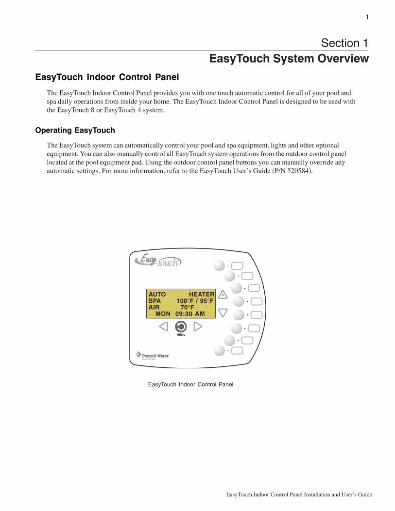
The EasyTouch Indoor Control Panel provides you with one touch automatic control for all of your pool andspa daily operations from inside your home. The EasyTouch Indoor Control Panel is designed to be used withthe EasyTouch 8 or EasyTouch 4 system.
Operating EasyTouch
The EasyTouch system can automatically control your pool and spa equipment, lights and other optionalequipment. You can also manually control all EasyTouch system operations from the outdoor control panellocated at the pool equipment pad. Using the outdoor control panel buttons you can manually override anyautomatic settings. For more information, refer to the EasyTouch User’s Guide (P/N 520584).
EasyTouch Indoor Control Panel
AUTO HEATERSPA 100°F / 95°FAIR 70°F MON 09:30 AM

2
EasyTouch Indoor Control Panel Installation and User’s Guide
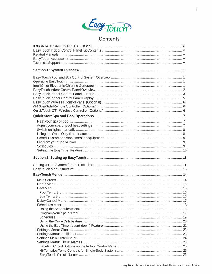
EasyTouch Indoor Control Panel Overview
The EasyTouch Indoor Control Panel makes it easy for you to control your pool and spa daily operations frominside your home. Using the “Pool” and “Spa” buttons allows one touch control to heat and filter your spa andpool. EasyTouch automatic system operations can be performed either at the Indoor Control Panel or from theoutdoor control panel. The Indoor Control Panel connects to the motherboard in the EasyTouch load center.
For details about thecontrol panel LCD status
messages, see page 5
AUTO HEATERSPA 100°F / 95°FAIR 70°F MON 09:30 AM
AUTO HEATERSPA 100°F / 95°FAIR 70°F MON 09:30 AM
Circuit LEDCircuit name label
Spa (Hi-Temp) Button: Switches the filterpump on, rotates valve actuator (to isolate spawater from pool water), and switches theheater on. Hi-Temp (EasyTouch single bodysystem) sets the high temperature settings forthe spa (see page 25)
Circuit LEDCircuit name label
Spa (Hi-Temp) Button:Switches the filter pump on,rotates valve actuator (toisolate spa water from poolwater), and switches the heateron. Hi-Temp (EasyTouch singlebody system) sets the hightemperature settings for thespa (see page 25)
Pool (Lo-Temp) Button: Switchesthe filter pump on, rotates valve
actuator (to isolate pool water fromspa water), and switches heater on.
Lo-Temp (EasyTouch single bodysystem) sets the low temperature
settings for the pool (see page 25)
Pool (Lo-Temp) Button:Switches the filter pump on,
rotates valve actuator (to isolatepool water from spa water), and
switches heater on.Lo-Temp (EasyTouch single
body system) sets the lowtemperature settings for the pool
(see page 25)
Indoor Control Panel (EasyTouch 8) - (P/N 520549)
Indoor Control Panel (EasyTouch 4) - (P/N 520548)
Seven user definedauxiliary circuits.Buttons switch theassigned circuit functionon/off (12 hour time-out).If solar equipment is notbeing used, use theAUX EXTRA (Downarrow button) for anadditional circuit (seepage 4 for details).
Seven user definedauxiliary circuits.Buttons switch theassigned circuit functionon/off (12 hour time-out).If solar equipment is notbeing used, use theAUX EXTRA (Downarrow button) for anadditional circuit (seepage 4 for details).
Menu/Back button,see page 4

3
EasyTouch Indoor Control Panel Installation and User’s Guide
EasyTouch Indoor Control Panel Buttons
Spa button/LED: For spa operations. Press this button to rotate valves and activate the filter pumpautomatically so that only the spa water is circulated through the system. If the heater is enabled,pressing this button also switches the heater on (if enabled in the Heat menu). When this button ispressed the circuit is activated, the LED is on and “SPA” is displayed on the screen with the currentand set point water temperatures. The default time before the filter pump will switch off is 12 hours.When this button is pressed, the LEDs on the outdoor control panel Filter Pump (F) button, Valves(V) button, and Heater button (if enabled in the Heat menu) will be on.
Pool Button: For pool operations. Press this button so that only the pool water is circulated throughthe system. Note that the filter pump will switch off while the pool/spa valves are rotating intoposition. If the heater is enabled, pressing this button also switches the heater on (if enabled in theHeat menu). When this button is pressed the circuit is activated and “POOL” is displayed on thescreen with actual and set point water temperatures. The default time before the filter pump willswitch off is 12 hours. When this button is pressed, the LEDs on the outdoor control panel FilterPump (F) button, Valves (V) button, and Heater button (if enabled in the Heat menu) will be on.
➀
➁
EasyTouch Indoor Control Panel Buttons
You can fully automate your pool, spa, and lighting operations from the EasyTouch Indoor Control Panel orfrom the outdoor control panel located at the pool equipment pad. The EasyTouch menu features let youcreate customized schedules for your pool and spa equipment, heat temperatures, and chlorination settings toswitch on and off at a set day and time. Scheduled automatic operations can be performed at the EasyTouchIndoor Control Panel or from the outdoor control panel. For menu options, refer to “EasyTouch MenuStructure,” on page 13. Before operating the EasyTouch Indoor Control Panel, familiarize yourself with theLCD status messages and operating buttons.
P
EasyTouch Indoor Control Panel
➁
➅ ➆
➇
➀
AUTO HEATERSPA 100°F / 95°FAIR 70°F MON 09:30 AM
➃
➂
➄

4
EasyTouch Indoor Control Panel Installation and User’s Guide
Controls and buttons (Continued)
Pool button (Continued)
• Single-Speed Filter Pump: If the pump is currently off, press the Pool button to switch the pumpon. Press the Pool button again to switch the pump off. However, if the heater is operating, and adelay is enabled for valves, this allows the heater to cool down (heater cool-down), then when youpress the Pool button to switch off the pump, only the heater will turn off, then the filter pump willautomatically switch off after 10 minutes to allow the heater to cool down. Pentair heaters do notrequire a cool down time. To override the “heater cool-down,” press the Pool button again to switchoff the pump.
• Two-Speed Filter Pump: Press the Pool button to switch the two-speed pump on in high speed.Press the Pool button again to run the pump in low speed. In order to use the “2-Speed Pump” menuassignments (see page 30), the 2-Speed relay option must be installed in the EasyTouch LoadCenter.
Notes about Freeze Protection: This function protects the pool, plumbing, and equipment againstfreeze damage. If the outside air temperature sensor falls below 36° F, “Freeze Protection” isactivated and the Filter Pump relay is switched on to circulate the pool water. To enable freezeprotection for a circuit, see “Settings Menu: Circuit Types, ” on page 27.
Liquid Crystal Display (LCD): The main system display consists of a 16 x 4 alphanumeric characterLCD with EL backlighting for easy viewing of the menu items, and status messages. Press theMenu button twice to refresh the display. For main screen status information, see page 5.
Left button: Use the Left button to scroll through sub-menu selections, setting and values. Whileediting settings, press and hold the Left button to fast reverse through settings and values.
Menu/Back button: Use the Menu/Back button to access, save and exit the EasyTouch systemmenu settings. Use this button to exit from main menu or sub-menu items. Pressing the Menu/Backbutton while in a menu item will return to the main status screen. If no menu activity is detectedafter five minutes, the main screen is displayed. All menu settings are permanently saved andretained in the control panel even after power is removed from the control panel. Control panelbuttons are disabled while in menu mode.
Right button: Use the Right button to select a sub-menu item for editing. After pressing the Menubutton to access the main menu items, use the Right button to select the menu item and access thesub-menu items for adjustment. For convenience, while editing a settings, press and hold the Rightbutton to fast forward through settings and values.
Up/Down buttons: Use the Up and Down buttons to scroll through the main menu items and toadjust or change settings. Use these buttons after pressing the Menu button to access the main menuitems. While editing settings, press and hold the Up or Down button to fast forward or fast reversethrough settings and values.
Down arrow button (Aux Extra): This button switches the assigned circuit on or off. This “extra”auxiliary circuit shares the solar circuit and is only available if the solar output plug (J17) on themotherboard is not being used for solar equipment. Refer to the EasyTouch User’s Guide(P/N 520584) for more information.
➄
➅
➂
➃
➆
MENU

5
EasyTouch Indoor Control Panel Installation and User’s Guide
➇
Controls and buttons (Continued)
AUX buttons/LEDs: The auxiliary output circuit buttons operate the pool and spa system valves,lights and other equipment. These auxiliary (AUX) circuits are assigned in the “Circuit Type” menu,see page 27 for details. There are three auxiliary circuits (AUX 1- 3) on the EasyTouch 4 indoorcontrol panel and seven auxiliary circuits (AUX 1- 7) on the EasyTouch 8 indoor control panel. TheDown arrow button can also be used as an “extra” auxiliary circuit if solar equipment is not beingused. Refer to “Down arrow button” on page 4 for more information. Labels can be affixed next toeach auxiliary button to identify the circuit function. When an auxiliary circuit is activated or thebutton is pressed, the LED is on. Pressing an auxiliary circuit button will activate the correspondingcircuit in either “Auto” or “Service” mode. When a circuit relay is switched on manually, it remainson until either you switch it off manually, or the next time the relay is scheduled to be switched off.For example, if the filter pump is scheduled to automatically run from 9:00 AM to 5:00 PM daily thenthe filter pump is switched on manually at 9:00 PM, it will run continuously until the next day at 5:00PM then switch off. The schedule will then continue from then on.
EasyTouch Indoor Control Panel Display
The Indoor Control Panel screen displays when the system is in automatic mode (AUTO) or in service mode(SERVICE). Service mode is enabled from EasyTouch outdoor control panel at the pool equipment pad. Thefollowing describes the main status screen.
AUTO (Automatic): The system is in normal operating mode.Scheduled programs will run automatically.
HEATER: Displays the heat source (Off, Heater, Solar Prf.,Solar) as specified in the Heater menu settings (see page 16).
POOL (Spa): Indicates that the Valves (V) button is in “Pool” or“Spa” mode and the Filter Pump (F) button has been pressed toswitch on the filter pump. If this display line is blank, it indicatesno spa or pool function is active. For an EasyTouch single bodysystem, Hi-Temp (Spa) / Lo-Temp (Pool) sets the temperaturesettings (see page 25)
95° F / 100° F: Displays the actual spa or pool water temperature(95° F) and the set point temperature (100° F) as set in the“Heater” menu.
AIR: Displays the actual outside air temperature (70° F) as readby the air sensor located near the EasyTouch Load Center.
Date and Time: Displays the EasyTouch system day and time asspecified in the “Clock” menu settings (see page 22).
AUTO HEATERSPA 95°F / 100°FAIR 70°F MON 09:30 AM

6
EasyTouch Indoor Control Panel Installation and User’s Guide
iS4 Spa-Side Remote Controller (Optional)
The iS4 Spa-Side remote controller is a double-insulated, waterproof device that is UL (1563) listed forinstallation at the water’s edge. Pentair recommends that the iS4 always be installed above the water line ofthe spa wall, or in the deck within arm’s reach of a spa occupant. The iS4 provides remote switching of up tofour control circuits from the spa location. It is typically used for activating spa circulation and any threeauxiliary pieces of equipment (such as lights, jet pump, air blower, etc.). The red status LED indicator glowssteady when in Spa mode and flashes while the spa is heating. For more about assigning circuits to the iS4buttons, refer to “Settings Menu: iS4 Spa-Side Remote controller,” on page 32. The iS4 two installation choicesare shown:
QuickTouch QT4 Wireless Controller(Optional)
The QuickTouch QT4wireless controllerprovides switching ofup to four circuits. Youcan use the QT4wireless controller toactivate the spacirculation, and foroperating threeauxiliary pieces ofequipment (such aslights, jet pump, airblower, waterfall, etc.). Each of the fourfunctions on the QT4 wireless controller has anon and an off button. For more about assigningcircuits to the QT4 buttons, refer to “SettingsMenu: QuickTouch (QT4) Wireless Remote,” onpage 33. Note: The QT4 wireless controller maybe used with wet hands, but should never besubmersed in water as this could damage theQT4. If accidental submersion occurs, dry theQT4 out by removing battery cover andremoving battery. Position the QT4 so that watercan drain out. Reassemble when the QT4 iscompletely dry.
QuickTouch (QT4) WirelessController (P/N 520148)
EasyTouch Wireless Control Panel(Optional)
The EasyTouch wireless control panel (8 or 4circuits) gives you the freedom to control yourpool and spa daily operations from around yourpool and spa area. The wireless device canoperate up to 300 feet from the EasyTouchtransceiver module which is typically locatednear the EasyTouch load center. There is enoughbattery power to operate the whole summerseason withoutchanging batteries,Using the powersaving menuoptions you canalso reduce powerconsumption andextend battery life.The EasyTouchwireless controlpanel is waterresistent, however,is not intended tobe submersible.The EasyTouch wireless control panel isdesigned to be used with the EasyTouch 8 orEasyTouch 4 system.
POWER ON
iS4 Spa-Side Remote Controller(Wall or tile mount)
iS4 Spa-Side Remote Controller(Deck mount)
1 2 3 4
Red power LEDindicator
3 2 1
Red powerLED indicator
4
EasyTouch wireless control panel,eight circuit (P/N 520547)

7
EasyTouch Indoor Control Panel Installation and User’s Guide
Quick start pool and spa operations
The following describes how to run some of the general day-to-day spa and pool operations.
Heat your spa or pool
First enable the heat source in the Heat menu (see “Heat Menu,” on page 20). Pressthe Spa button (top button) to switch the filter pump on, rotate the valve actuator (toisolate spa water from pool water), and switch the heater on. Note: By default, thesetting “Man Heat’ is set to “On” (see page 34) which allows the spa to begin toheat whenever it is manually turned on. Press the Pool button to switch the filterpump on, rotate the valve actuator (to isolate pool water from spa water), and switchthe heater on. For Pool and Spa button location, see page 2.
Adjust your spa or pool heat settings
From the “Heat” menu ( > Heat > Spa Temp/Src/Pool Temp/Src) you can select the heat source and
set the water temperature. The spa or pool water will heat to the settings specified. The EasyTouch systemallows for solar and conventional heaters. The EasyTouch will use the heating source that is selected. Theheat source selections are:
• OFF - No heating even though pump and other circuits may be operating.• HEATER - Gas heater only.• SOLAR ONLY - Solar heating system to be the only heat source. In order to display “Solar Only” as a
heat option in the “Heat” menu, you must first enable solar in the Settings > Solar menu(see page 30).
• SOLAR PREF. (Solar Preferred) - Used if solar and gas heating are combined and you want to usesolar heating only when it is most effective. In order to display “Solar Preferred” as a heat option inthe “Heat” menu, you must first enable solar in the Settings > Solar menu (see page 30).
To set the spa temperature set point and select the heat source:
Right button: Select spa temperature and heat source.Up/Down button: Adjust the spa water temperature.(from 40° F to 106° F or 4° C to 41° C).Right or Left button: Move to Heat source options.Up/Down: Set the Heat option: Off, Heater, Solar, or Solar Preferred.
Press the Back button save the settings and to return to the Heat menu or press
the button again to return to the Main screen.
Note: Select “Pool Temp/Src” to adjust your pool temperature.
AUTO HEATERSPA 95°F / 100°FAIR 70°F MON 09:30 AM
Pool Temp/Src Spa Temp/Src
Spa
Temp: 85° FHeat: Off
Getting There
▼ HEAT

8
EasyTouch Indoor Control Panel Installation and User’s Guide
Switch on lights manually
From the Lights screen you can manually switch all lights on or off, and synchronize colored lights. Up to 12lights can be controlled. For more information about setting up lights, refer to “Lights Menu” onpage 15.
To manually switch on all lights:
Up/Down button: Select: All off, All on, or Sync. The Sync feature allows acombination of up to 12 SAm, SAL, or FIBERworks lights to synchronize their colorsbefore switching the lights on.
Press the Back button save the settings and to return to the main menu items or
press the button again to return to the Main screen.
Using the Once Only timer feature
The Schedules “Once Only” timer feature enables you to automatically switch equipment on for one time. Thisfeature allows you to program a circuit to turn on at a particular time on a one-time basis. For example, if youwanted the spa to be heated when you arrive home, you could program the heater to switch on at a specifictime and after you have finished using the spa you can switch the heater off manually. After the program hasrun, it is automatically erased. Unlike using the regular “Schedule” program, the “Once Only” program doesnot repeat. The circuit must be turned off manually or wait for the 12 hour automatic shut-off. However, youcould also reset the 12 hour factory shut-off by entering an “Egg Timer” count down program to extend pastthe default 12 hours shut-off.
The following example describes how to set a “Once Only “ program for the spa. The same steps apply whenselecting the pool or any auxiliary circuit.
Right button: Select the Spa circuit.Right button: Select Mode if there are existing programs. Skip this step to create anew program.Up/Down button: Select New to create a new program.Right button: To create a new program and enter the “Mode” settings.Up/Down button: 1/1 indicates that this circuit has one program. If there are existingprograms assigned to this circuit, use these buttons to view and select the existingprogram settings.Right button: To select the “Once Only” settings.Right button: Move to start time settings.Up/Down and Right buttons: Set the start hour (A/P) and minutes. A (AM) andP (PM) time is set when setting the start hour.Right button: Move to day of the week to run the program.Right button: Select which day to run the program then press the Up/Down buttonto enable the bar on top of the letter. A bar on top of the letter indicates the dayselected to run the program.
Press the Back button to save the settings and to return to the Schedules menu
options. Press the button again to return to the main menu options or press again toreturn to the Main screen.
Setup Lights
Mode: All Off
Getting There
LIGHTS SETUP LIGHTS▲
Getting There
▼ SCHEDULES SPA▲
Spa 0/0Mode: None (New)
Spa 0 Pool 0 Aux 1 0 Aux 2 0
Spa 1/1Mode: Once Only08:00As m t w t f s _

9
EasyTouch Indoor Control Panel Installation and User’s Guide
Schedule start and stop times for equipment
You can set timers (schedules) to automatically run equipment like pool filtration or lights. Any EasyTouchcircuit can be set to switch on and off on every or any day of the week. Up to 12 total programs may becreated for all circuits combined.
Program your Spa or Pool
You can use the “Schedule” feature to set the time and day(s) when to switch the filter pump on and rotate thepool/spa valves into the “Pool” or “Spa” position. The heater will automatically heat the pool or spa water upto the set point temperature as set in the “Heat” menu (see page 16). If the pool has a separate jet pump orblower controlled by AUX 1 and/or AUX 2 , these need to be scheduled separately.
Schedules
To create a schedule for your spa or pool:
Right button: Select the Spa circuit. The generic circuit names are: Spa, Pool,Aux1-7 (EasyTouch 8), Aux 1-3 (EasyTouch 4), and Aux Extra “Aux Extra” is onlyavailable if the Solar output (J17) plug on the EasyTouch motherboard is not beingused for solar equipment.
Right button: Select Mode if there are existing programs. Skip this step to create anew program.Up/Down button: Select New to create a new program.Right button: To create a new program and enter the “Mode” settings.
Up/Down button: 1/1 indicates that this circuit has one program. If there are existingprograms assigned to this circuit, use these buttons to view and select the existingprogram settings.Right button: To select the “Schedule” settings.Right button: Move to start and stop time settings.Up/Down and Right buttons: Set start and stop hour (A/P), minutes.The A (AM) and P (PM) time is set when setting the start and stop hour.Right button: Move to days of the week to run the program.Right and Up/Down buttons: By default the program is set to run all the days ofthe week. If you wish to edit which days to run the program, select the day of theweek, then press the Up/Down button to remove the bar from the top of the letter. Abar on top of the letter indicates the day selected to run the program.
Press the Back button to save the settings and to return to the Schedules menu
options. Press the button again to return to the main menu options or press again toreturn to the Main screen.
Getting There
▼ SCHEDULES SPA▲
Spa 0/0Mode: None (New)
Spa 0 Pool 0 Aux 1 0 Aux 2 0
Spa 1/1Mode: Schedule08:00A - 05:00Ps m t w t f s_ _ _ _ _ _ _
10
EasyTouch Indoor Control Panel Installation and User’s Guide
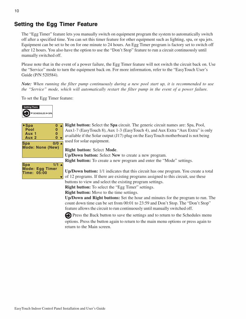
Setting the Egg Timer Feature
The “Egg Timer” feature lets you manually switch on equipment program the system to automatically switchoff after a specified time. You can set this timer feature for other equipment such as lighting, spa, or spa jets.Equipment can be set to be on for one minute to 24 hours. An Egg Timer program is factory set to switch offafter 12 hours. You also have the option to use the “Don’t Stop” feature to run a circuit continuously untilmanually switched off.
Please note that in the event of a power failure, the Egg Timer feature will not switch the circuit back on. Usethe “Service” mode to turn the equipment back on. For more information, refer to the “EasyTouch User’sGuide (P/N 520584).
Note: When running the filter pump continuously during a new pool start up, it is recommended to usethe “Service” mode, which will automatically restart the filter pump in the event of a power failure.
To set the Egg Timer feature:
Right button: Select the Spa circuit. The generic circuit names are: Spa, Pool,Aux1-7 (EasyTouch 8), Aux 1-3 (EasyTouch 4), and Aux Extra “Aux Extra” is onlyavailable if the Solar output (J17) plug on the EasyTouch motherboard is not beingused for solar equipment.
Right button: Select Mode.Up/Down button: Select New to create a new program.Right button: To create a new program and enter the “Mode” settings.
Up/Down button: 1/1 indicates that this circuit has one program. You create a totalof 12 programs. If there are existing programs assigned to this circuit, use thesebuttons to view and select the existing program settings.Right button: To select the “Egg Timer” settings.Right button: Move to the time settings.Up/Down and Right buttons: Set the hour and minutes for the program to run. Thecount down time can be set from 00:01 to 23:59 and Don’t Stop. The “Don’t Stop”feature allows the circuit to run continuously until manually switched off.
Press the Back button to save the settings and to return to the Schedules menu
options. Press the button again to return to the main menu options or press again toreturn to the Main screen.
Spa 1/1Mode: Egg TimerTime: 05:00
Getting There
▼ SCHEDULES SPA▲
Spa 0/0Mode: None (New)
Spa 0 Pool 0 Aux 1 0 Aux 2 0
11
EasyTouch Indoor Control Panel Installation and User’s Guide
Section 2Setting up EasyTouch
Setting up the System for the First Time
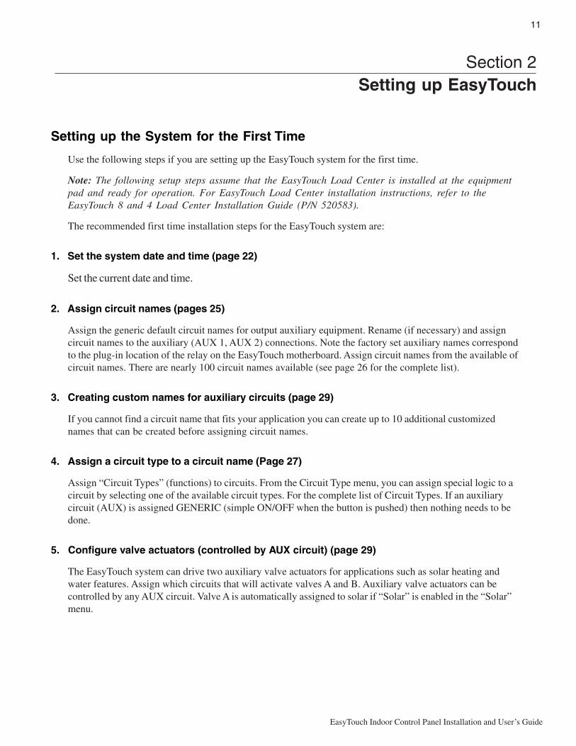
Use the following steps if you are setting up the EasyTouch system for the first time.
Note: The following setup steps assume that the EasyTouch Load Center is installed at the equipmentpad and ready for operation. For EasyTouch Load Center installation instructions, refer to theEasyTouch 8 and 4 Load Center Installation Guide (P/N 520583).
The recommended first time installation steps for the EasyTouch system are:
1. Set the system date and time (page 22)
Set the current date and time.
2. Assign circuit names (pages 25)
Assign the generic default circuit names for output auxiliary equipment. Rename (if necessary) and assigncircuit names to the auxiliary (AUX 1, AUX 2) connections. Note the factory set auxiliary names correspondto the plug-in location of the relay on the EasyTouch motherboard. Assign circuit names from the available ofcircuit names. There are nearly 100 circuit names available (see page 26 for the complete list).
3. Creating custom names for auxiliary circuits (page 29)
If you cannot find a circuit name that fits your application you can create up to 10 additional customizednames that can be created before assigning circuit names.
4. Assign a circuit type to a circuit name (Page 27)
Assign “Circuit Types” (functions) to circuits. From the Circuit Type menu, you can assign special logic to acircuit by selecting one of the available circuit types. For the complete list of Circuit Types. If an auxiliarycircuit (AUX) is assigned GENERIC (simple ON/OFF when the button is pushed) then nothing needs to bedone.
5. Configure valve actuators (controlled by AUX circuit) (page 29)
The EasyTouch system can drive two auxiliary valve actuators for applications such as solar heating andwater features. Assign which circuits that will activate valves A and B. Auxiliary valve actuators can becontrolled by any AUX circuit. Valve A is automatically assigned to solar if “Solar” is enabled in the “Solar”menu.

12
EasyTouch Indoor Control Panel Installation and User’s Guide
6. Set up optional equipment, solar, 2-speed pump (page 29 and 30)
Set up additional equipment such as solar, 2-speed pump, and optional equipment if required. Set up thecontrol panel to operate with the optional IntelliChlor chlorine generator. To configure EasyTouch for specialequipment:
• Is solar heating available? Is solar being used for a heat pump?
• What circuits will turn 2-Speed pumps to High Speed?
• Cool-down cycle for the heater - Lets you set circuits that switch the filter pump to high speed.
• Do you want to delay turning off the filter pump for 10 minutes when the heater is turned off?
• Do you want the spa to heat whenever the Spa button is pressed?
7. Configuring the heater system options (page 16)
Set the type of heat source being used (Heater, Solar, Solar Preferred).
8. Configure the iS4 spa-side remote, QuickTouch wireless remote buttons (page 32 and 33)
Assign four circuits to the iS4 and/or QuickTouch remote buttons. Once you have checked that all buttonsoperate properly, place labels on remote buttons.
9. Set the delays feature (page 31)
Enable the one time “delay” feature for the heater, 2-speed pump, and automatic pool cleaner.
10. Schedule on/off times for circuit (page 18 - 21)
Set times for automatic circuit activation. Up to 12 total programs can be created for all circuits combined.One circuit can have up to a maximum of 9 programs (9/9), which leaves 3 programs that can be used by onecircuit or three separate circuits for a total of 12 programs. All user created programs are active all the time;so check that there are not conflicting automated times.
11. Setup the lighting settings (page 15)
From the lighting menu you can enable special control of your pool and yard lighting, such as rotating coloredlights, and synchronized colored lights.
13
EasyTouch Indoor Control Panel Installation and User’s Guide
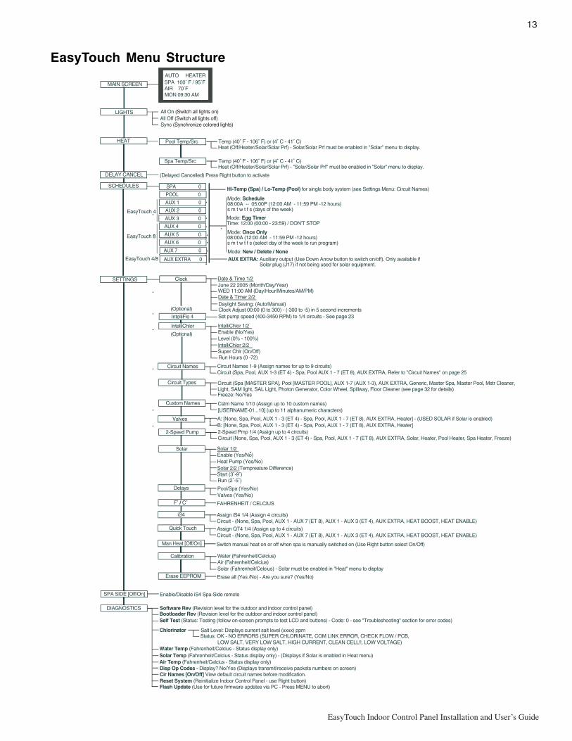
EasyTouch Menu Structure
MAIN SCREEN
AUTO HEATERSPA 100˚ F / 95˚FAIR 70˚FMON 09:30 AM
LIGHTS All On (Switch all lights on)All Off (Switch all lights off)Sync (Synchronize colored lights)
HEAT
DIAGNOSTICS Software Rev (Revision level for the outdoor and indoor control panel)Bootloader Rev (Revision level for the outdoor and indoor control panel)Self Test (Status: Testing (follow on-screen prompts to test LCD and buttons) - Code: 0 - see "Troubleshooting" section for error codes)
Water Temp (Fahrenheit/Celcius - Status display only)Solar Temp (Fahrenheit/Celcius - Status display only) - (Displays if Solar is enabled in Heat menu)Air Temp (Fahrenheit/Celcius - Status display only)
Pool Temp/Src Temp (40˚ F - 106˚ F) or (4˚ C - 41˚ C)Heat (Off/Heater/Solar/Solar Prf) - Solar/Solar Prf must be enabled in "Solar" menu to display.
Spa Temp/Src Temp (40˚ F - 106˚ F) or (4˚ C - 41˚ C)Heat (Off/Heater/Solar/Solar Prf) - "Solar/Solar Prf" must be enabled in "Solar" menu to display.
DELAY CANCEL
Mode: Schedule08:00A -- 05:00P (12:00 AM - 11:59 PM -12 hours)s m t w t f s (days of the week)
SCHEDULES SPA 0
AUX 2 0
AUX 4 0
AUX 3 0 Mode: Egg Timer Time: 12:00 (00:00 - 23:59) / DON'T STOP
SETTINGS
IntelliChlorEnable (No/Yes)Level (0% - 100%)IntelliChlor 2/2
Run Hours (0 -72)
IntelliChlor 1/2
Super Chlr (On/Off)
(Optional)
Circuit NamesCircuit (Spa, Pool, AUX 1-3 (ET 4) - Spa, Pool AUX 1 - 7 (ET 8), AUX EXTRA, Refer to "Circuit Names" on page 25Circuit Names 1-9 (Assign names for up to 9 circuits)
Circuit Types Circuit (Spa [MASTER SPA], Pool [MASTER POOL], AUX 1-7 (AUX 1-3), AUX EXTRA, Generic, Master Spa, Master Pool, Mstr Cleaner,
Freeze: No/Yes
Custom Names Cstm Name 1/10 (Assign up to 10 custom names) [USERNAME-01...10] (up to 11 alphanumeric characters)
2-Speed PumpCircuit (None, Spa, Pool, AUX 1 - 3 (ET 4) - Spa, Pool, AUX 1 - 7 (ET 8), AUX EXTRA, Solar, Heater, Pool Heater, Spa Heater, Freeze) 2-Speed Pmp 1/4 (Assign up to 4 circuits)
Solar
Delays Pool/Spa (Yes/No) Valves (Yes/No)
Enable (Yes/No) Heat Pump (Yes/No)Solar 2/2 (Tempreature Difference)
Run (2˚-5˚)
Solar 1/2
Start (3˚-9˚)
Valves
Clock
F˚ / C˚
iS4
FAHRENHEIT / CELCIUS
Quick Touch Assign QT4 1/4 (Assign up to 4 circuits)Circuit - (None, Spa, Pool, AUX 1 - AUX 7 (ET 8), AUX 1 - AUX 3 (ET 4), AUX EXTRA, HEAT BOOST, HEAT ENABLE)
Erase EEPROM Erase all (Yes /No) - Are you sure? (Yes/No)
Circuit - (None, Spa, Pool, AUX 1 - AUX 7 (ET 8), AUX 1 - AUX 3 (ET 4), AUX EXTRA, HEAT BOOST, HEAT ENABLE) Assign iS4 1/4 (Assign 4 circuits)
CalibrationAir (Fahrenheit/Celcius)Solar (Fahrenheit/Celcius) - Solar must be enabled in "Heat" menu to display
Water (Fahrenheit/Celcius)
Date & Time 1/2 June 22 2005 (Month/Day/Year)WED 11:00 AM (Day/Hour/Minutes/AM/PM) Date & Timer 2/2Daylight Saving: (Auto/Manual)Clock Adjust 00:00 (0 to 300) - (-300 to -5) in 5 sceond increments
(Delayed Cancelled) Press Right button to activate
A: [None, Spa, Pool, AUX 1 - 3 (ET 4) - Spa, Pool, AUX 1 - 7 (ET 8), AUX EXTRA, Heater] - (USED SOLAR if Solar is enabled)B: [None, Spa, Pool, AUX 1 - 3 (ET 4) - Spa, Pool, AUX 1 - 7 (ET 8), AUX EXTRA, Heater]
Disp Op Codes - Display? No/Yes (Displays transmit/receive packets numbers on screen)
SPA SIDE [Off/On]
POOL 0
AUX 1 0
AUX 5 0
AUX 6 0
AUX 7 0
Enable/Disable iS4 Spa-Side remote
Light, SAM light, SAL Light, Photon Generator, Color Wheel, Spillway, Floor Cleaner (see page 32 for details)
Cir Names [On/Off] View default circuit names before modification.
Chlorinator Salt Level: Displays current salt level (xxxx) ppmStatus: OK - NO ERRORS (SUPER CHLORINATE, COM LINK ERROR, CHECK FLOW / PCB, LOW SALT, VERY LOW SALT, HIGH CURRENT, CLEAN CELL!!, LOW VOLTAGE)
Man Heat [Off/On] Switch manual heat on or off when spa is manually switched on (Use Right button select On/Off)
EasyTouch 4
EasyTouch 8Mode: Once Only08:00A (12:00 AM - 11:59 PM -12 hours)s m t w t f s (select day of the week to run program)
Mode: New / Delete / None
Reset System (Reinitialize Indoor Control Panel - use Right button)
Hi-Temp (Spa) / Lo-Temp (Pool) for single body system (see Settings Menu: Circuit Names)
Flash Update (Use for future firmware updates via PC - Press MENU to abort)
IntelliFlo 4 Set pump speed (400-3450 RPM) to 1/4 circuits - See page 23
(Optional)
AUX EXTRA 0EasyTouch 4/8 AUX EXTRA: Auxiliary output (Use Down Arrow button to switch on/off). Only available if Solar plug (J17) if not being used for solar equipment.
14
EasyTouch Indoor Control Panel Installation and User’s Guide
EasyTouch Menus
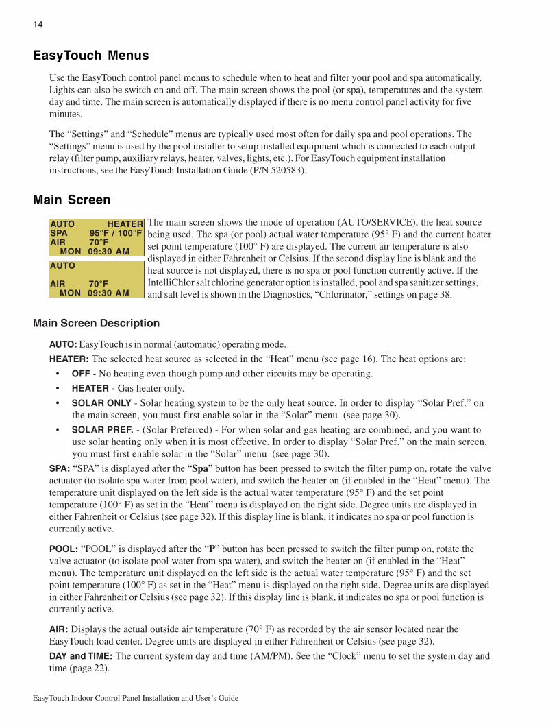
Use the EasyTouch control panel menus to schedule when to heat and filter your pool and spa automatically.Lights can also be switch on and off. The main screen shows the pool (or spa), temperatures and the systemday and time. The main screen is automatically displayed if there is no menu control panel activity for fiveminutes.
The “Settings” and “Schedule” menus are typically used most often for daily spa and pool operations. The“Settings” menu is used by the pool installer to setup installed equipment which is connected to each outputrelay (filter pump, auxiliary relays, heater, valves, lights, etc.). For EasyTouch equipment installationinstructions, see the EasyTouch Installation Guide (P/N 520583).
Main Screen
The main screen shows the mode of operation (AUTO/SERVICE), the heat sourcebeing used. The spa (or pool) actual water temperature (95° F) and the current heaterset point temperature (100° F) are displayed. The current air temperature is alsodisplayed in either Fahrenheit or Celsius. If the second display line is blank and theheat source is not displayed, there is no spa or pool function currently active. If theIntelliChlor salt chlorine generator option is installed, pool and spa sanitizer settings,and salt level is shown in the Diagnostics, “Chlorinator,” settings on page 38.
Main Screen Description
AUTO: EasyTouch is in normal (automatic) operating mode.
HEATER: The selected heat source as selected in the “Heat” menu (see page 16). The heat options are:
• OFF - No heating even though pump and other circuits may be operating.
• HEATER - Gas heater only.
• SOLAR ONLY - Solar heating system to be the only heat source. In order to display “Solar Pref.” onthe main screen, you must first enable solar in the “Solar” menu (see page 30).
• SOLAR PREF. - (Solar Preferred) - For when solar and gas heating are combined, and you want touse solar heating only when it is most effective. In order to display “Solar Pref.” on the main screen,you must first enable solar in the “Solar” menu (see page 30).
SPA: “SPA” is displayed after the “Spa” button has been pressed to switch the filter pump on, rotate the valveactuator (to isolate spa water from pool water), and switch the heater on (if enabled in the “Heat” menu). Thetemperature unit displayed on the left side is the actual water temperature (95° F) and the set pointtemperature (100° F) as set in the “Heat” menu is displayed on the right side. Degree units are displayed ineither Fahrenheit or Celsius (see page 32). If this display line is blank, it indicates no spa or pool function iscurrently active.
POOL: “POOL” is displayed after the “P” button has been pressed to switch the filter pump on, rotate thevalve actuator (to isolate pool water from spa water), and switch the heater on (if enabled in the “Heat”menu). The temperature unit displayed on the left side is the actual water temperature (95° F) and the setpoint temperature (100° F) as set in the “Heat” menu is displayed on the right side. Degree units are displayedin either Fahrenheit or Celsius (see page 32). If this display line is blank, it indicates no spa or pool function iscurrently active.
AIR: Displays the actual outside air temperature (70° F) as recorded by the air sensor located near theEasyTouch load center. Degree units are displayed in either Fahrenheit or Celsius (see page 32).
DAY and TIME: The current system day and time (AM/PM). See the “Clock” menu to set the system day andtime (page 22).
AUTO HEATERSPA 95°F / 100°FAIR 70°F MON 09:30 AM
AUTO
AIR 70°F MON 09:30 AM

15
EasyTouch Indoor Control Panel Installation and User’s Guide
Lights Menu
From the Lights screen you can manually switch all lights on or off, and synchronize colored lights. If youhave at least two Pentair SAm and/or SAL, and/or FIBERworks lighting systems you can use the Sync featureto change the lighting settings. This feature require a separate auxiliary relay circuit for each light. Up to fourlights can be assigned on each auxiliary circuit for a total of 12 lights that can be independently controlled fromthe Lights menu.
Make sure the AUX relay circuits which control your lighting have been assigned names. Then verify thatSAm and/or SAL, and/or FIBERworks have been set up in “Circuit Types” as SAM or SAL lights. IfFIBERworks lighting is incorporated, it also has to be set up as a “PHOTON GENERATOR” for the circuitcontrolling the light bulb, and COLOR WHEEL for the circuit controlling the color wheel. For moreinformation about setting up lights, see “Settings Menu: Circuit Types,” on page 27.
Lights
To configure lights:
Up/Down button: Select: All off, All on, or Sync.
Press the Back button save the settings and to return to the main menu items or
press the button again to return to the Main screen.
The lights options are:
All Off: Switch all lights off manually.
All On: Switch all lights on manually.
Sync: Causes all colored lights to synchronize their colors.
Setup Lights
Mode: All Off
Getting There
LIGHTS SETUP LIGHTS▲

16
EasyTouch Indoor Control Panel Installation and User’s Guide
Heat Menu
Use the heat menu settings to specify the set point temperature and select the heat source for the pool and spawater. The water will begin to heat whenever the heater is manually switched on, (by pressing the “Pool” or“Spa” button or the Valves (V) button outdoor control panel), even if the heater is set to off. The spa will alsobegin to heat when switched on by the optional iS4 Spa-Side remote, or EasyTouch wireless remote. TheEasyTouch system allows for solar and conventional heaters. The EasyTouch will use the heating source thatis selected. The heat source selections are:
• OFF - No heating even though pump and other circuits may be operating.
• HEATER - Gas heater only. Use the Heater button to automatically switch the heater on whichcontrols the output between a “forced off” state and a normal, automatic thermostatic controloperating state. The heater will continue heating the water until the heater’s current highest set pointtemperature triggers the heater sensor (approximately 106° F or 41° C). Note that the Heater buttonon the control panel does not activate the pump. Do not activate the heater without running the pump.The heater will not run if water flow is not detected.
• SOLAR ONLY - Solar heating system to be the only heat source. In order to display “Solar Pref.” onthe main screen, you must first enable solar in the “Solar” menu (see page 30).
• SOLAR PREF. (Solar Preferred) - Solar and gas heating systems are installed, and you want to usesolar heating only when it is most effective. In order to display “Solar Pref.” on the main screen, youmust first enable solar in the “Solar” menu (see page 30). To set the spa temperature and select theheat source:
Pool Temp/Src
To set the pool temperature and select the heat source:
Right button: Select pool temperature and heater options.Up/Down button: Set the pool temperature (from 40° F to 106° F).Right or Left button: Move to Heater option.Up/Down: Set Heater option: Off, Heater, Solar, or Solar Preferred.
Press the Back button save the settings and to return to the previous menu or
press the button again to return to the Main screen.
Spa Temp/Src
To set the spa temperature and select the heat source:
Right button: Select spa temperature and heater options.Up/Down button: Set the spa temperature (from 40° F to 106° F or 4° C to 41° C).Right or Left button: Move to Heater option.Up/Down: Set Heater option: Off, Heater, Solar, or Solar Preferred.
Press the Back button save the settings and to return to the Heat menu or press
the button again to return to the Main screen.
Spa
Temp: 85° FHeat: Off
Getting There
▼ HEAT
Pool
Temp: 72° FHeat: Off
Pool Temp/Src Spa Temp/Src
Pool Temp/Src Spa Temp/Src
Note: For an EasyTouch single body system, “Pool” and “Spa” modes are Lo- Temp (Pool) andHi-Temp (Spa) temperature controls. For more information, see “Hi-Temp/Lo-Temp Controls for SingleBody Systems,” on page 25.

17
EasyTouch Indoor Control Panel Installation and User’s Guide
Delay Cancel Menu
Use the Delay Cancel feature for service or testing purposes. For convenience, on a one time basis, the DelayCancel feature will cancel the following safety delays. Please note, generally there is no need to cancel any ofthe following delays except for servicing or testing the system.
• Heater Cool-Down Delay Cancel: Shuts Filter Pump off immediately.
• 2-Speed Filter Pump five-minute START on HIGH SPEED Delay Cancel: Shifts pump to lowspeed.
• Automatic Pool Cleaner START Delay: Starts Cleaner Pump immediately, without normal delay inwhich the filter pump first runs for 5 minutes.
• Automatic Pool Cleaner SOLAR Delay: Allows Cleaner Pump to run even though solar delay hasshut it off for five minutes.
Some heaters require a cool-down cycle before being switched off. This can be setup in the menu to run thefilter pump an additional ten minutes to dissipate residual heat built up inside the heater combustion chamber.The Delay Cancel feature is mainly for use by service technicians when it’s necessary to shut the filter pumpoff immediately, and know the heater has not been running. Heaters manufactured by Pentair do not requirethis cool-down period and do not need the delay to be set up.
Note: For Information about assigning delays to the pool and spa valves, refer to “Settings Menu:Delays” on page 31.
Delay Cancel
To activate Delay Cancel:
Up/Down button: Select Delay Cancel.Right button: Use this button activate Delay Cancel for one time only. “DelayCancelled” is displayed after pressing the Right button.
Press the Back button to return to the Main screen.
Getting There
▼ DELAY CANCEL ▲
LightsHeatDelay CancelSchedules
18
EasyTouch Indoor Control Panel Installation and User’s Guide
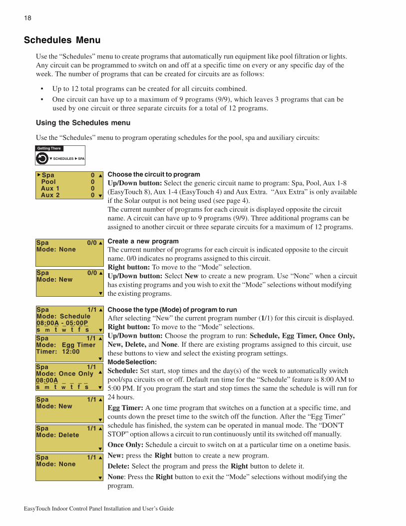
Schedules Menu
Use the “Schedules” menu to create programs that automatically run equipment like pool filtration or lights.Any circuit can be programmed to switch on and off at a specific time on every or any specific day of theweek. The number of programs that can be created for circuits are as follows:
• Up to 12 total programs can be created for all circuits combined.
• One circuit can have up to a maximum of 9 programs (9/9), which leaves 3 programs that can beused by one circuit or three separate circuits for a total of 12 programs.
Using the Schedules menu
Use the “Schedules” menu to program operating schedules for the pool, spa and auxiliary circuits:
Choose the circuit to programUp/Down button: Select the generic circuit name to program: Spa, Pool, Aux 1-8(EasyTouch 8), Aux 1-4 (EasyTouch 4) and Aux Extra. “Aux Extra” is only availableif the Solar output is not being used (see page 4).The current number of programs for each circuit is displayed opposite the circuitname. A circuit can have up to 9 programs (9/9). Three additional programs can beassigned to another circuit or three separate circuits for a maximum of 12 programs.
Create a new programThe current number of programs for each circuit is indicated opposite to the circuitname. 0/0 indicates no programs assigned to this circuit.Right button: To move to the “Mode” selection.Up/Down button: Select New to create a new program. Use “None” when a circuithas existing programs and you wish to exit the “Mode” selections without modifyingthe existing programs.
Choose the type (Mode) of program to runAfter selecting “New” the current program number (1/1) for this circuit is displayed.Right button: To move to the “Mode” selections.Up/Down button: Choose the program to run: Schedule, Egg Timer, Once Only,New, Delete, and None. If there are existing programs assigned to this circuit, usethese buttons to view and select the existing program settings.Mode Selection:Schedule: Set start, stop times and the day(s) of the week to automatically switchpool/spa circuits on or off. Default run time for the “Schedule” feature is 8:00 AM to5:00 PM. If you program the start and stop times the same the schedule is will run for24 hours.
Egg Timer: A one time program that switches on a function at a specific time, andcounts down the preset time to the switch off the function. After the “Egg Timer”schedule has finished, the system can be operated in manual mode. The “DON'TSTOP” option allows a circuit to run continuously until its switched off manually.
Once Only: Schedule a circuit to switch on at a particular time on a onetime basis.
New: press the Right button to create a new program.
Delete: Select the program and press the Right button to delete it.
None: Press the Right button to exit the “Mode” selections without modifying theprogram.
Spa 0/0Mode: None
Spa 0 Pool 0 Aux 1 0 Aux 2 0
Spa 1/1Mode: Egg TimerTimer: 12:00
Spa 1/1Mode: Once Only08:00As m t w t f s_ _ _ _ _ _ _
Spa 1/1Mode: Schedule08:00A - 05:00Ps m t w t f s_ _ _ _ _ _ _
Spa 1/1Mode: Delete
Spa 1/1Mode: None
Spa 0/0Mode: New
Getting There
▼ SCHEDULES SPA▲
Spa 1/1Mode: New
19
EasyTouch Indoor Control Panel Installation and User’s Guide
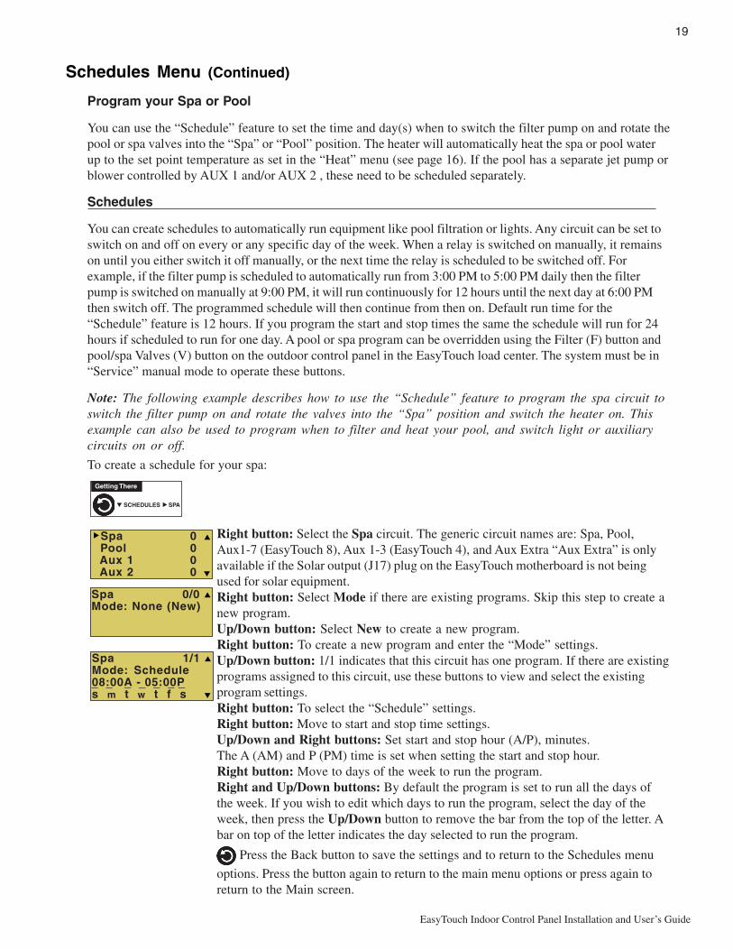
Schedules Menu (Continued)
Program your Spa or Pool
You can use the “Schedule” feature to set the time and day(s) when to switch the filter pump on and rotate thepool or spa valves into the “Spa” or “Pool” position. The heater will automatically heat the spa or pool waterup to the set point temperature as set in the “Heat” menu (see page 16). If the pool has a separate jet pump orblower controlled by AUX 1 and/or AUX 2 , these need to be scheduled separately.
Schedules
You can create schedules to automatically run equipment like pool filtration or lights. Any circuit can be set toswitch on and off on every or any specific day of the week. When a relay is switched on manually, it remainson until you either switch it off manually, or the next time the relay is scheduled to be switched off. Forexample, if the filter pump is scheduled to automatically run from 3:00 PM to 5:00 PM daily then the filterpump is switched on manually at 9:00 PM, it will run continuously for 12 hours until the next day at 6:00 PMthen switch off. The programmed schedule will then continue from then on. Default run time for the“Schedule” feature is 12 hours. If you program the start and stop times the same the schedule will run for 24hours if scheduled to run for one day. A pool or spa program can be overridden using the Filter (F) button andpool/spa Valves (V) button on the outdoor control panel in the EasyTouch load center. The system must be in“Service” manual mode to operate these buttons.
Note: The following example describes how to use the “Schedule” feature to program the spa circuit toswitch the filter pump on and rotate the valves into the “Spa” position and switch the heater on. Thisexample can also be used to program when to filter and heat your pool, and switch light or auxiliarycircuits on or off.
To create a schedule for your spa:
Right button: Select the Spa circuit. The generic circuit names are: Spa, Pool,Aux1-7 (EasyTouch 8), Aux 1-3 (EasyTouch 4), and Aux Extra “Aux Extra” is onlyavailable if the Solar output (J17) plug on the EasyTouch motherboard is not beingused for solar equipment.Right button: Select Mode if there are existing programs. Skip this step to create anew program.Up/Down button: Select New to create a new program.Right button: To create a new program and enter the “Mode” settings.Up/Down button: 1/1 indicates that this circuit has one program. If there are existingprograms assigned to this circuit, use these buttons to view and select the existingprogram settings.Right button: To select the “Schedule” settings.Right button: Move to start and stop time settings.Up/Down and Right buttons: Set start and stop hour (A/P), minutes.The A (AM) and P (PM) time is set when setting the start and stop hour.Right button: Move to days of the week to run the program.Right and Up/Down buttons: By default the program is set to run all the days ofthe week. If you wish to edit which days to run the program, select the day of theweek, then press the Up/Down button to remove the bar from the top of the letter. Abar on top of the letter indicates the day selected to run the program.
Press the Back button to save the settings and to return to the Schedules menu
options. Press the button again to return to the main menu options or press again toreturn to the Main screen.
Getting There
▼ SCHEDULES SPA▲
Spa 0/0Mode: None (New)
Spa 0 Pool 0 Aux 1 0 Aux 2 0
Spa 1/1Mode: Schedule08:00A - 05:00Ps m t w t f s_ _ _ _ _ _ _

20
EasyTouch Indoor Control Panel Installation and User’s Guide
Using the Once Only feature
The “Once Only” feature allows you to program a circuit to switch on at a particular time and day on aonetime basis. A typical use for this feature is to have the spa and heater switch on before you get home fromwork for one evening. Unlike the regular “Schedule” timer, this feature does not repeat. After this event hasfinished, the program is automatically erased. The circuit must be switched off manually or wait for the 12hour automatic shut off. If you wish to override the 12 hour default shut-off time you can extend the time byusing the “Egg Timer” countdown feature (page 21).
Note: The following example describes how use the “Once Only” feature to program the spa circuit toswitch the filter pump on and rotate the valves into the “Spa” position and switch the heater on for onetime only. This example can also be used if you wanted to program when to filter and heat your pool,and switch light or auxiliary circuits on.
The set a “Once Only Timer” program for the spa.
Right button: Select the Spa circuit. The generic circuit names are: Spa, Pool,Aux1-7 (EasyTouch 8), Aux 1-3 (EasyTouch 4), and Aux Extra “Aux Extra” is onlyavailable if the Solar output (J17) plug on the EasyTouch motherboard is not beingused for solar equipment.
Right button: Select Mode if there are existing programs. Skip this step to create anew program.Up/Down button: Select New to create a new program.Right button: To create a new program and enter the “Mode” settings.
Up/Down button: 1/1 indicates that this circuit has one program. If there are existingprograms assigned to this circuit, use these buttons to view and select the existingprogram settings.Right button: To select the “Once Only” settings.Right button: Move to start time settings.Up/Down and Right buttons: Set the start hour (A/P) and minutes. A (AM) andP (PM) time is set when setting the start hour. Note: if the Start Time is set to an hourwhich has already passed, then the program will be executed the following day.Another day of the week may also be chosen. The stop time will be 12 hours later, orcan be turned off manually. The 12-hour shut off can be changed to any length oftime by entering another program using the “Egg Timer” program (page 21).Right button: Move to day of the week to run the program.Right button: Select which day to run the program then press the Up/Down buttonto enable the bar on top of the letter. A bar on top of the letter indicates the dayselected to run the program.
Press the Back button to save the settings and to return to the Schedules menu
options. Press the button again to return to the main menu options or press again toreturn to the Main screen.
Getting There
▼ SCHEDULES SPA▲
Spa 0/0Mode: None (New)
Spa 0 Pool 0 Aux 1 0 Aux 2 0
Spa 1/1Mode: Once Only08:00As m t w t f s _
21
EasyTouch Indoor Control Panel Installation and User’s Guide
Using the Egg Timer (countdown) Feature
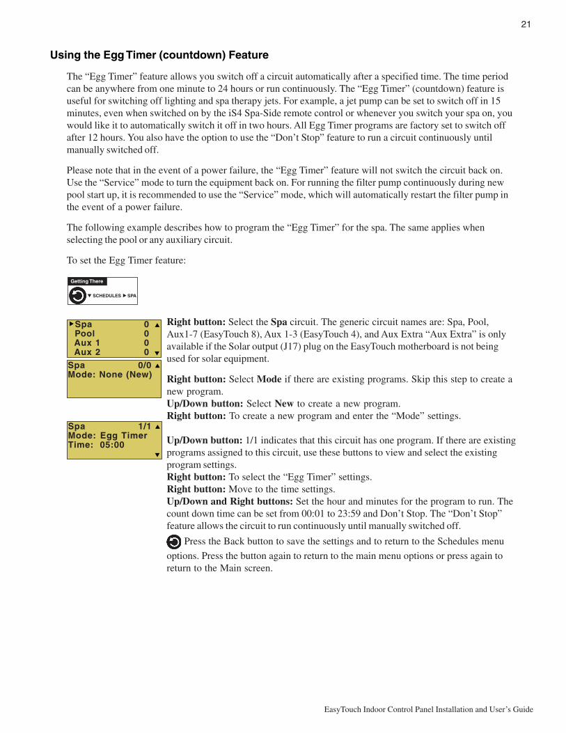
The “Egg Timer” feature allows you switch off a circuit automatically after a specified time. The time periodcan be anywhere from one minute to 24 hours or run continuously. The “Egg Timer” (countdown) feature isuseful for switching off lighting and spa therapy jets. For example, a jet pump can be set to switch off in 15minutes, even when switched on by the iS4 Spa-Side remote control or whenever you switch your spa on, youwould like it to automatically switch it off in two hours. All Egg Timer programs are factory set to switch offafter 12 hours. You also have the option to use the “Don’t Stop” feature to run a circuit continuously untilmanually switched off.
Please note that in the event of a power failure, the “Egg Timer” feature will not switch the circuit back on.Use the “Service” mode to turn the equipment back on. For running the filter pump continuously during newpool start up, it is recommended to use the “Service” mode, which will automatically restart the filter pump inthe event of a power failure.
The following example describes how to program the “Egg Timer” for the spa. The same applies whenselecting the pool or any auxiliary circuit.
To set the Egg Timer feature:
Right button: Select the Spa circuit. The generic circuit names are: Spa, Pool,Aux1-7 (EasyTouch 8), Aux 1-3 (EasyTouch 4), and Aux Extra “Aux Extra” is onlyavailable if the Solar output (J17) plug on the EasyTouch motherboard is not beingused for solar equipment.
Right button: Select Mode if there are existing programs. Skip this step to create anew program.Up/Down button: Select New to create a new program.Right button: To create a new program and enter the “Mode” settings.
Up/Down button: 1/1 indicates that this circuit has one program. If there are existingprograms assigned to this circuit, use these buttons to view and select the existingprogram settings.Right button: To select the “Egg Timer” settings.Right button: Move to the time settings.Up/Down and Right buttons: Set the hour and minutes for the program to run. Thecount down time can be set from 00:01 to 23:59 and Don’t Stop. The “Don’t Stop”feature allows the circuit to run continuously until manually switched off.
Press the Back button to save the settings and to return to the Schedules menu
options. Press the button again to return to the main menu options or press again toreturn to the Main screen.
Spa 1/1Mode: Egg TimerTime: 05:00
Getting There
▼ SCHEDULES SPA▲
Spa 0/0Mode: None (New)
Spa 0 Pool 0 Aux 1 0 Aux 2 0
22
EasyTouch Indoor Control Panel Installation and User’s Guide
Settings Menu: Clock
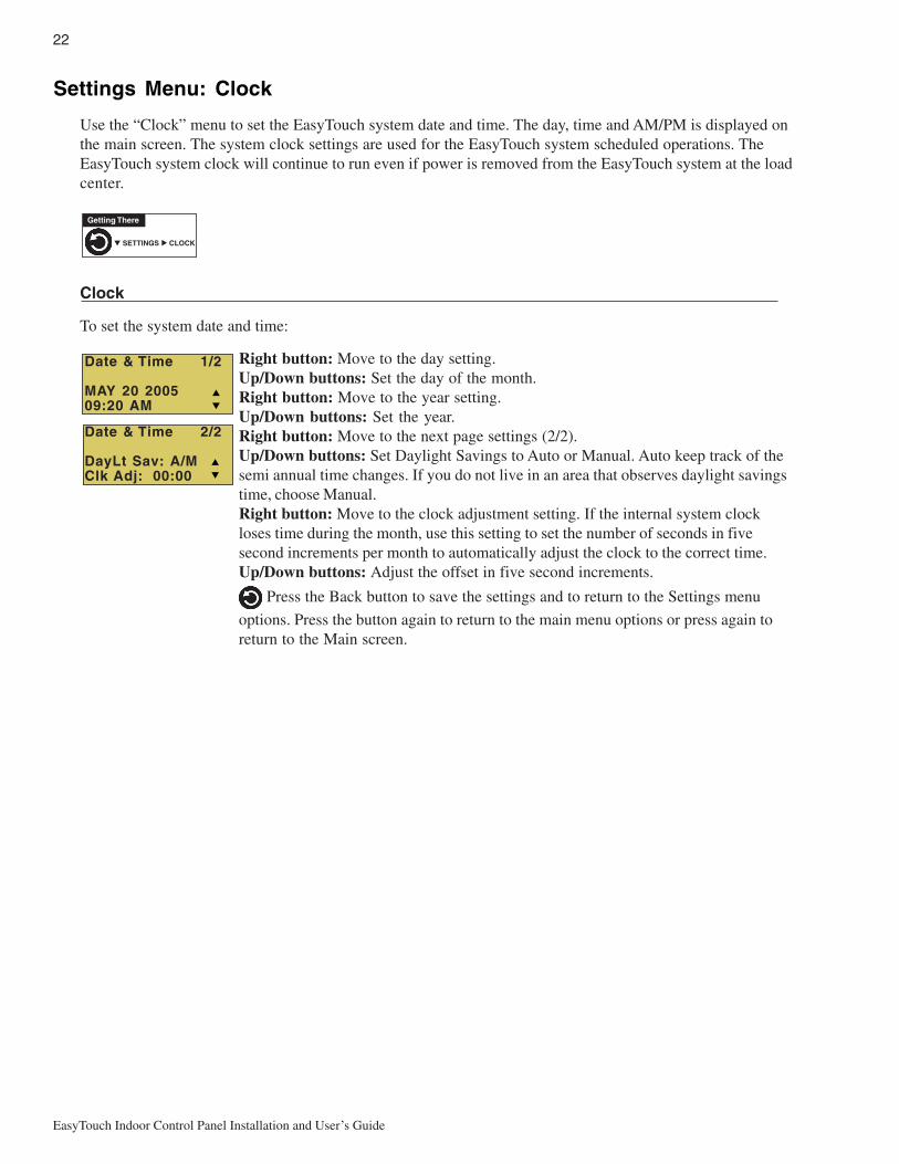
Use the “Clock” menu to set the EasyTouch system date and time. The day, time and AM/PM is displayed onthe main screen. The system clock settings are used for the EasyTouch system scheduled operations. TheEasyTouch system clock will continue to run even if power is removed from the EasyTouch system at the loadcenter.
Clock
To set the system date and time:
Right button: Move to the day setting.Up/Down buttons: Set the day of the month.Right button: Move to the year setting.Up/Down buttons: Set the year.Right button: Move to the next page settings (2/2).Up/Down buttons: Set Daylight Savings to Auto or Manual. Auto keep track of thesemi annual time changes. If you do not live in an area that observes daylight savingstime, choose Manual.Right button: Move to the clock adjustment setting. If the internal system clockloses time during the month, use this setting to set the number of seconds in fivesecond increments per month to automatically adjust the clock to the correct time.Up/Down buttons: Adjust the offset in five second increments.
Press the Back button to save the settings and to return to the Settings menu
options. Press the button again to return to the main menu options or press again toreturn to the Main screen.
Getting There
▼ SETTINGS CLOCK▲
Date & Time 1/2
MAY 20 200509:20 AM
Date & Time 2/2
DayLt Sav: A/MClk Adj: 00:00

23
EasyTouch Indoor Control Panel Installation and User’s Guide
Settings Menu: IntelliFlo 4
IntelliFlo 4 Variable Speed Pump
This feature allows you to assign a circuit to control the IntelliFlo 4 pump speed. The pump speed can beadjusted to run from 400 to 3450 RPM in increments of 10 RPM. For more information about the IntelliFlopump, refer to the IntelliFlo 4 Installation and User’s Guide (P/N 357269).
IntelliFlo 4
To adjust the speed of the IntelliFlo 4 pump:
Up/Down buttons: Select the circuit number 1 of 4 (1/4). The default speed for eachcircuit correspond to the four speed buttons on the IntelliFlo control panel. The presetspeed for each button is: Speed 1 button 750 RPM, Speed 2 button 1500 RPM, Speed3 button 2350 RPM, and Speed 4 button 3110 RPM.Right button: Move to RPM to change the pump speed.Up/Down buttons: Set speed of the pump from 400 to 3450 RPM in increments of10 RPM.Right button: Move to the circuit names.Up/Down buttons: Assign the circuit: None, Spa, Pool, Aux1-7 (EasyTouch 8),Aux 1-3 (EasyTouch 4), Aux Extra (only available if Solar is not enabled - see page31, Heater, Pool Heater, Spa Heater, Freeze, andHi-Speed. “Aux Extra” is only available if the Solar output (J17) plug on theEasyTouch motherboard is not being used for solar equipment. Use the Down arrowbutton to switch the “extra” circuit on and off.Right button: Press the Up arrow button and go to the next circuit page settings(2/4) and repeat the previous steps.
When finished setting up the circuits, press the Back button to save the settings
and to return to the Settings menu options. Press the button two times to return to themain screen.
IntelliFlo 4 external control
EasyTouch communicates with the IntelliFlo 4 pump via a two-wire RS-485 cable. For information aboutconnecting the RS-485 communication cable from EasyTouch to the IntelliFlo pump, refer to the IntelliFlo 4Installation and User’s Guide (P/N 357269).
IntelliFlo 4 1/4RPM: 1500Circuit:[ AUX 1 ]
▼ SETTINGS ▼ INTELLIFLO 4 4 SPD PUMP
Getting There
▲

24
EasyTouch Indoor Control Panel Installation and User’s Guide
Settings Menu: IntelliChlor
The IntelliChlor electronic chlorination system must be connected to the EasyTouch system to use thefollowing IntelliChlor settings. While in normal operating mode (“Pool,” “Spa” mode or “Spa Fill (Spillway),”EasyTouch will control the chlorinator output level. When IntelliChlor is connected to the EasyTouch outdoorcontrol panel, chlorination levels can only be changed from the outdoor control panel or the Indoor ControlPanel. The amount of chlorine introduced into the pool is determined by the amount of salt in the water, watertemperature, and the amount of time the pool operates in “Pool” mode. Note: While in “Freeze Protection”mode, IntelliChlor will not operate during the time that the filter pump is operating. For more information, referto the IntelliChlor Electronic Chlorine Generator User’s Guide (P/N 520589).
IntelliChlor
To setup the IntelliChlor system:
Right button: Move to Enable/Disable settings. (To select the second page settings,press the Up/Down button to change the first digit to 2/2).Up/Down buttons: Select Yes or No to enable or disable the IntelliChlor system.Right button: Move to the “Level” settings.Up/Down buttons: Set the chlorination output level for the pool/spa water from 0 to100%. EasyTouch will determine the chlorinator output level when the system isoperating in “Spa” or “Pool” mode. The amount of chlorine introduced into the pool/sap is determined by the amount of salt in the water, water temperature, and theamount of time the pool/spa operates in these modes mode.Right button: Move to the next page settings (2/2).Up/Down buttons: Select 2/2.Right button: Move the Super Chlorination settings.Up/Down buttons: Set Super Chlorination On or Off. See note below about SuperChlorination.Right button: Move to “Run Hours” setting.Up/Down buttons: Set the number of hours to run Super Chlorination. 24 hours isthe default setting. Run hours can be set from 0 to 72 hours.
Press the Back button to save the settings and to return to the Settings menu
options. Press the button again to return to the main menu options or press again toreturn to the Main screen.
Note: For IntelliChlor status messages, see “Diagnostics: Chlorinator” onpage 38.
About Super Chlorination: The Super Chlorination feature is used to introduce large amounts of chlorineinto the pool water if there has been heavy rain fall, many bathers in the pool, cloudy water conditions, etc.When Super Chlorination is enabled, the system will switch on the filter pump, set the pool/spa valves to thecorrect position, and set the IntelliChlor chlorine generator to maximum output. This process continues for 24hours. At the end of the Super Chlorination process, the pool will return to normal operation. It is possible tomanually stop the Super Chlorination process and switch off the filter pump using the Filter (F) button on thecontrol panel. When the filter pump is switched on again using the Filter (F) button, the Super Chlorine processwill resume for the duration of time left.
IntelliChlor 1/2
Enable: NoLevel: 50%
IntelliChlor 2/2
Super Chlr: OffRun Hours: 24
▼ SETTINGS ▼ INTELLICLOR INTELLICHLOR
Getting There
▲
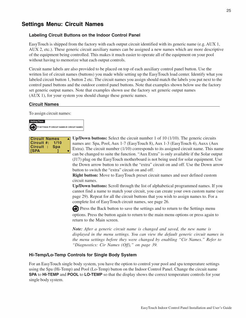
25
EasyTouch Indoor Control Panel Installation and User’s Guide
Settings Menu: Circuit Names
Labeling Circuit Buttons on the Indoor Control Panel
EasyTouch is shipped from the factory with each output circuit identified with its generic name (e.g. AUX 1,AUX 2, etc.). These generic circuit auxiliary names can be assigned a new names which are more descriptiveof the equipment being controlled. This makes it much easier to operate all of the equipment on your poolwithout having to memorize what each output controls.
Circuit name labels are also provided to be placed on top of each auxiliary control panel button. Use thewritten list of circuit names (buttons) you made while setting up the EasyTouch load center. Identify what youlabeled circuit button 1, button 2 etc. The circuit names you assign should match the labels you put next to thecontrol panel buttons and the outdoor control panel buttons. Note that examples shown below use the factoryset generic output names. Note that examples shown use the factory set generic output names(AUX 1), for your system you should change these generic names.
Circuit Names
To assign circuit names:
Up/Down buttons: Select the circuit number 1 of 10 (1/10). The generic circuitsnames are: Spa, Pool, Aux 1-7 (EasyTouch 8), Aux 1-3 (EasyTouch 4), Auxx (AuxExtra). The circuit number (1/10) corresponds to its assigned circuit name. This namecan be changed to suite the function. “Aux Extra” is only available if the Solar output(J17) plug on the EasyTouch motherboard is not being used for solar equipment. Usethe Down arrow button to switch the “extra” circuit on and off. Use the Down arrowbutton to switch the “extra” circuit on and off.Right button: Move to EasyTouch preset circuit names and user defined customcircuit names.Up/Down buttons: Scroll through the list of alphabetical programmed names. If youcannot find a name to match your circuit, you can create your own custom name (seepage 29). Repeat for all the circuit buttons that you wish to assign names to. For acomplete list of EasyTouch circuit names, see page 26.
Press the Back button to save the settings and to return to the Settings menu
options. Press the button again to return to the main menu options or press again toreturn to the Main screen.
Note: After a generic circuit name is changed and saved, the new name isdisplayed in the menu settings. You can view the default generic circuit names inthe menu settings before they were changed by enabling “Cir Names.” Refer to“Diagnostics: Cir Names (Off),” on page 39.
Hi-Temp/Lo-Temp Controls for Single Body System
For an EasyTouch single body system, you have the option to control your pool and spa temperature settingsusing the Spa (Hi-Temp) and Pool (Lo-Temp) button on the Indoor Control Panel. Change the circuit nameSPA to HI-TEMP and POOL to LO-TEMP so that the display shows the correct temperature controls for yoursingle body system.
▼ SETTINGS ▼ CIRCUIT NAMES CIRCUIT NAMES
Getting There
▲
Circuit NamesCircuit #: 1/10Circuit : Spa[SPA ]

26
EasyTouch Indoor Control Panel Installation and User’s Guide
EasyTouch Circuit Names
AERATORAIR BLOWERAUX 1AUX 2AUX 3AUX 4AUX 5AUX 6AUX 7AUX 8AUX 9AUX 10AUX EXTRABACKWASHBACK LIGHTBBQ LIGHTBEACH LIGHTBOOSTER PUMPBUG LIGHTCABANA LTSCHEM. FEEDERCHLORINATORCLEANERCOLOR WHEELDECK LIGHTDRAIN LINEDRIVE LIGHTEDGE PUMPENTRY LIGHTFANFIBER OPTICFIBERWORKSFILL LINEFLOOR CLNRFOGGERFOUNTAINFOUNTAIN 1FOUNTAIN 2FOUNTAIN 3FOUNTAINSFRONT LIGHTGARDEN LTSGAZEBO LTSHIGH SPEEDHI-TEMPHOUSE LIGHTJETSLIGHTSLOW SPEEDLO-TEMPMALIBU LTSMISTMUSIC
Custom Circuit Names (11 characters maximum)
USERNAME-01 ____________________
USERNAME-02 ____________________
USERNAME-03 ____________________
USERNAME-04 ____________________
USERNAME-05 ____________________
USERNAME-06 ____________________
USERNAME-07 ____________________
USERNAME-08 ____________________
USERNAME-09 ____________________
USERNAME-10 ____________________
NOT USEDOZONATORPATH LIGHTSPATIO LTSPERIMETER LPG2000POND LIGHTPOOL PUMPPOOLPOOL HIGHPOOL LIGHTPOOL LOWPOOL SAMPOOL SAM 1POOL SAM 2POOL SAM 3SECURITY LTSLIDESOLARSPASPA HIGHSPA LIGHTSPA LOWSPA SALSPA SAMSPA WTRFLLSPILLWAYSPRINKLERSSTREAMSTATUE LTSWIM JETSWTR FEATUREWTR FEAT LTWATERFALLWATERFALL 1WATERFALL 2WATERFALL 3WHIRLPOOLWTRFL LGHTYARD LIGHT
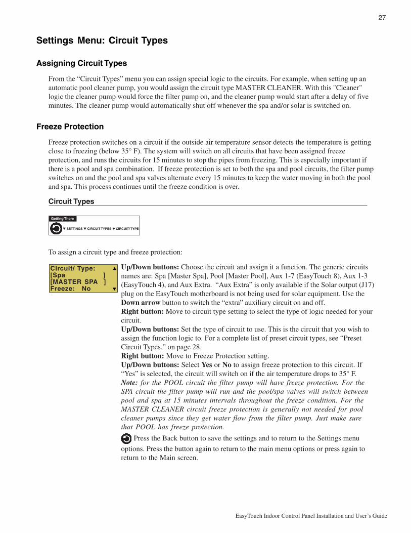
27
EasyTouch Indoor Control Panel Installation and User’s Guide
Settings Menu: Circuit Types
Assigning Circuit Types
From the “Circuit Types” menu you can assign special logic to the circuits. For example, when setting up anautomatic pool cleaner pump, you would assign the circuit type MASTER CLEANER. With this "Cleaner"logic the cleaner pump would force the filter pump on, and the cleaner pump would start after a delay of fiveminutes. The cleaner pump would automatically shut off whenever the spa and/or solar is switched on.
Freeze Protection
Freeze protection switches on a circuit if the outside air temperature sensor detects the temperature is gettingclose to freezing (below 35° F). The system will switch on all circuits that have been assigned freezeprotection, and runs the circuits for 15 minutes to stop the pipes from freezing. This is especially important ifthere is a pool and spa combination. If freeze protection is set to both the spa and pool circuits, the filter pumpswitches on and the pool and spa valves alternate every 15 minutes to keep the water moving in both the pooland spa. This process continues until the freeze condition is over.
Circuit Types
To assign a circuit type and freeze protection:
Up/Down buttons: Choose the circuit and assign it a function. The generic circuitsnames are: Spa [Master Spa], Pool [Master Pool], Aux 1-7 (EasyTouch 8), Aux 1-3(EasyTouch 4), and Aux Extra. “Aux Extra” is only available if the Solar output (J17)plug on the EasyTouch motherboard is not being used for solar equipment. Use theDown arrow button to switch the “extra” auxiliary circuit on and off.Right button: Move to circuit type setting to select the type of logic needed for yourcircuit.Up/Down buttons: Set the type of circuit to use. This is the circuit that you wish toassign the function logic to. For a complete list of preset circuit types, see “PresetCircuit Types,” on page 28.Right button: Move to Freeze Protection setting.Up/Down buttons: Select Yes or No to assign freeze protection to this circuit. If“Yes” is selected, the circuit will switch on if the air temperature drops to 35° F.Note: for the POOL circuit the filter pump will have freeze protection. For theSPA circuit the filter pump will run and the pool/spa valves will switch betweenpool and spa at 15 minutes intervals throughout the freeze condition. For theMASTER CLEANER circuit freeze protection is generally not needed for poolcleaner pumps since they get water flow from the filter pump. Just make surethat POOL has freeze protection.
Press the Back button to save the settings and to return to the Settings menu
options. Press the button again to return to the main menu options or press again toreturn to the Main screen.
▼ SETTINGS ▼ CIRCUIT TYPES CIRCUIT/ TYPE
Getting There
▲
Circuit/ Type:[Spa ][MASTER SPA ]Freeze: No

28
EasyTouch Indoor Control Panel Installation and User’s Guide
Preset Circuit Types
cireneG elbammargorpehtllahtiwtiucricafolortnocffO/nOelpmiS.cigoLlaicepsoN.seitilibapac
apSretsaM ehtseodtI.rotautcaevlavrenaelcrospmuprenaelcloopcitamotuahtiwskroW:gniwollof
.nosehctiwspmuprenaelcehterofebsetunim5nopmupretlifehtsecroF-
.nosiapsehtnehwfforenaelcehthctiwS-
.snigebgnitaehralosehtnehwsetunim5roffforenaelcehthctiwS-
looPretsaM ehtseodtI.rotautcaevlavrenaelcrospmuprenaelcloopcitamotuahtiwskroW:gniwollof
.nosehctiwspmuprenaelcehterofebsetunim5nopmupretlifehtsecroF-
.nosiapsehtnehwfforenaelcehthctiwS-
.snigebgnitaehralosehtnehwsetunim5roffforenaelcehthctiwS-
renaelCretsaM ehtseodtI.rotautcaevlavrenaelcrospmuprenaelcloopcitamotuahtiwskroW:gniwollof
.nosehctiwspmuprenaelcehterofebsetunim5nopmupretlifehtsecroF-
.nosiapsehtnehwfforenaelcehthctiwS-
.snigebgnitaehralosehtnehwsetunim5roffforenaelcehthctiwS-
thgiL .ffosthgilLLAronosthgilLLAsahcus,krowotserutaefgnithgillaicepsswollA
thgiLMAS lenaPlortnoCroodnIehtnosneercsrehtonosmargorpgnithgilroloclaicepssetavitcALLAronosthgilLLAevahnacuoy,elpmaxeroF.sthgilloopMAShtiwdesunehw
.ffosthgil
thgiLLAS lenaPlortnoCroodnIehtnosneercsrehtonosmargorpgnithgilroloclaicepssetavitcAhtiwdesunehw LAS evahnacuoy,elpmaxeroF.sthgilaps sthgilLLAronosthgilLLA
ffo .
rotareneGnotohP ,cnySserutaefunemsthgiLybdetarepoebblubcitporebifskrowrebiFriatnePsteL.gnithgilLASdnaMAShtiwdesunehwFFOLLAdnaNOLLA,etatoR
leehWroloC lenaPlortnoCroodnIehtnosneercsrehtonosmargorpgnithgilroloclaicepssetavitcALLAronosthgilLLAevahnacuoy,elpmaxeroF.skrowrebiFriatnePhtiwdesunehw
.ffosthgil
yawllipS sevomgnittessihT.loopehtevobadesiarsiapsehterehwsnoitanibmocaps/looproFottisnruterdnaloopehtmorfretawehtslluppmupretlifehttahtosevlavnruterehtsihtnehwffodenruterasrenaelcloopcitamotuA.tceffellafretawagnitaerc,apseht
.nodenrutsierutaef
renaelCroolF renaelc2neewtebwolfgnitanretlasetunim02yreveevlavyaw-3asevomgnittessihT.sdaehpu-popehtdeeftahtsevlavmetsys

29
EasyTouch Indoor Control Panel Installation and User’s Guide
Settings Menu: Custom Names
There are nearly 100 circuit names available to choose from. If you cannot find one to fit your application youcan create up to 10 custom names. Each name can be up to 11 alphanumeric characters. After a custom nameis saved, it is then available for selection in the Schedules, 2-Speed Pump, iS4 and QuickTouch menus.
Custom Name
To assign a custom circuit name:
Up/Down buttons: Select a custom circuit name number (1-10). You can create upto 10 custom circuit names.Right button: Move to custom circuit name setting.Up/Down/Right buttons: Enter the custom circuit name (11 characters maximum).
Press the Back button to save the settings and to return to the Settings menu
options. Press the button again to return to the main menu options or press again toreturn to the Main screen.
Settings Menu: Valves
This feature lets you assign a circuit to Valve A or B. The EasyTouch system can drive two auxiliary valveactuators (A and B) for applications such as solar heating and water features. By assigning AUX circuits tocontrol valve actuators, you can conserve auxiliary circuits for high voltage relays for controlling pumps andlights.
Valve A: Resides on the motherboard. If solar heating is setup and is not configured as a heat pump, then thisValve A is dedicated for controlling the solar heating valve actuator.Valve B: Resides on the motherboard. Can be configured to be controlled by any circuit.
Valves
To assign a circuit to Valve A and Valve B:
Up/Down buttons: Select a circuit to assign to Valve A. The generic circuitselections are: The generic circuits names are: None, Spa, Pool, Aux 1-7(EasyTouch 8), Aux 1-3 (EasyTouch 4), Aux Extra and Heater. “Aux Extra” is onlyavailable if the Solar output (J17) plug on the EasyTouch motherboard is not beingused for solar equipment.Right button: Move to Valve B setting.Up/Down buttons: Select a circuit to assign to Valve B. The generic circuits namesare: None, Spa, Pool, Aux 1-7 (EasyTouch 8), Aux 1-3 (EasyTouch 4), Aux Extra andHeater. “Aux Extra” is only available if the Solar output (J17) plug on the EasyTouchmotherboard is not being used for solar equipment.
Press the Back button to save the settings and to return to the Settings menu
options. Press the button again to return to the main menu options or press again toreturn to the Main screen.
▼ SETTINGS ▼ CUSTOM NAMES CSTM NAME
Getting There
▲
Cstm Name 1/10
[USERNAME-01]
▼ SETTINGS ▼ VALVES SETUP VALVES
Getting There
▲
Set Valves
A: [CLEANER ]B: [FOUNTAIN ]
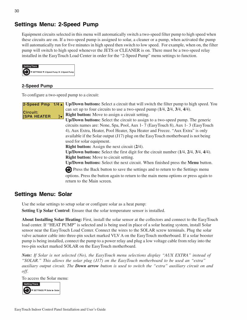
30
EasyTouch Indoor Control Panel Installation and User’s Guide
Settings Menu: 2-Speed Pump
Equipment circuits selected in this menu will automatically switch a two-speed filter pump to high speed whenthese circuits are on. If a two-speed pump is assigned to solar, a cleaner or a pump, when activated the pumpwill automatically run for five minutes in high speed then switch to low speed. For example, when on, the filterpump will switch to high speed whenever the JETS or CLEANER is on. There must be a two-speed relayinstalled in the EasyTouch Load Center in order for the “2-Speed Pump” menu settings to function.
2-Speed Pump
To configure a two-speed pump to a circuit:
Up/Down buttons: Select a circuit that will switch the filter pump to high speed. Youcan set up to four circuits to use a two-speed pump (1/4, 2/4, 3/4, 4/4).Right button: Move to assign a circuit setting.Up/Down buttons: Select the circuit to assign to a two-speed pump. The genericcircuits names are: None, Spa, Pool, Aux 1- 7 (EasyTouch 8), Aux 1- 3 (EasyTouch4), Aux Extra, Heater, Pool Heater, Spa Heater and Freeze. “Aux Extra” is onlyavailable if the Solar output (J17) plug on the EasyTouch motherboard is not beingused for solar equipment.Right button: Assign the next circuit (2/4).Up/Down buttons: Select the first digit for the circuit number (1/4, 2/4, 3/4, 4/4).Right button: Move to circuit setting.Up/Down buttons: Select the next circuit. When finished press the Menu button.
Press the Back button to save the settings and to return to the Settings menu
options. Press the button again to return to the main menu options or press again toreturn to the Main screen.
Settings Menu: Solar
Use the solar settings to setup solar or configure solar as a heat pump:
Setting Up Solar Control: Ensure that the solar temperature sensor is installed.
About Installing Solar Heating: First, install the solar sensor at the collectors and connect to the EasyTouchload center. If “HEAT PUMP” is selected and is being used in place of a solar heating system, install Solarsensor near the EasyTouch Load Center. Connect the wires to the SOLAR screw terminals. Plug the solarvalve actuator cable into three-pin socket marked VLV A on the EasyTouch motherboard. If a solar boosterpump is being installed, connect the pump to a power relay and plug a low voltage cable from relay into thetwo-pin socket marked SOLAR on the EasyTouch motherboard.
Note: If Solar is not selected (No), the EasyTouch menu selections display “AUX EXTRA” instead of“SOLAR.” This allows the solar plug (J17) on the EasyTouch motherboard to be used an “extra”auxiliary output circuit. The Down arrow button is used to switch the “extra” auxiliary circuit on andoff.
To access the Solar menu:
▼ SETTINGS ▼ Solar Solar
Getting There
▲
▼ SETTINGS ▼ 2-Speed Pump 2-Speed Pump
Getting There
▲
2-Speed Pmp 1/4
Circuit:[SPA HEATER ]

31
EasyTouch Indoor Control Panel Installation and User’s Guide
Solar
To enable a solar heater and set the temperature start and run time settings:
Up/Down buttons: Select Yes or No to enable solar (1/2). In order to display thesolar selection as a heat source on the main screen, select Yes.Right button: Move to the Heat Pump setting.Up/Down buttons: Select Yes or No to enable solar as a heat pump. Heat PumpControl instead of Solar: Select Yes if a heat pump is being used in place of a solarheating system. If Solar is set to heat pump, Valve A is free for other circuits.Right button: Select page 2 of 4 (2/4) to access the solar temperature differentialstart up and run settings.Up/Down buttons:Start: Set the temperature differential to start heating from 3° to 9°. For example, if“Start” is set to 3°, this ensures that the temperature has to deviate by 3° at least tothe specified set point temperature (in the Heat menu, page 16) before it switches on.Once the solar comes on it will start converging as it is heating. This ensures that itwill not continually be switching on and off.Run: Set the temperature differential to stop heating from 2° to 5°. This setting setshow close to the target set point temperature to switch off solar heat.
Press the Back button to save the settings and to return to the Settings menu
options. Press the button again to return to the main menu options or press again toreturn to the Main screen.
Settings Menu: DelaysSetup which functions (pool/spa, and valves) to assign the delay feature. Delays can be assigned to thefollowing equipment.
• Heater Cool-Down Delay Cancel: Shuts Filter Pump off immediately.• 2-Speed Filter Pump five-minute START on HIGH SPEED Delay Cancel: Shifts pump to low
speed.• Automatic Pool Cleaner START Delay: Starts Cleaner Pump immediately, without normal delay in
which the filter pump first runs for 5 minutes.• Automatic Pool Cleaner SOLAR Delay: Allows Cleaner Pump to run even though solar delay has
shut it off for 5 minutes.Some heaters require a cool-down cycle before being switched off. This can be setup to run the filter pump anadditional ten minutes to dissipate residual heat built up inside the heater combustion chamber. You can alsocancel the delay feature. For information about using the cancel delay feature, refer to “Delay Cancel” onpage 17.
Delays
To assign the delay feature:
Press the Up/Down buttons to select Yes or No to enable or disable delays for thepool and spa circuits. Press the Right button to move to the valves setting. Press theDown buttons to select Yes or No to enable or disable delays for valves. Press the
Back button to save and to return to the Settings menu options. Press the button
again to return to the main menu or press again to go to the main screen.
Delays
Pool/Spa: NoValves: No
▼ SETTINGS ▼ Delays Delays
Getting There
▲
Solar 1/2
Enable: YesHeat Pump: No
Solar 2/2
Start: 6°Run : 4°

32
EasyTouch Indoor Control Panel Installation and User’s Guide
Settings Menu: F° / C° (Fahrenheit/Celsius)
The temperature settings for the water, solar and air can be displayed in either Fahrenheit or Celsius.
F° / C°
To change the temperature units:
Up/Down buttons: Select either Fahrenheit or Celsius.
Press the Back button to save the settings and to return to the Settings menu
options. Press the button again to return to the main menu options or press again toreturn to the Main screen.
Settings Menu: iS4 Spa-Side Remote Controller
You can specify any iS4 Spa-Side remote button to control different functions by assigning each button to aspecific circuit. For example, you can use the iS4 Spa-Side remote to activate the spa circulation, and foroperating three auxiliary pieces of equipment (such as heat enabled, lights, jet pump, heat boost, air blower,waterfall, etc.).
Assign iS4
Before configuring the iS4 Spa-Side remote controller assign names to the circuits (see page 24).
To assign iS4 Spa-Side buttons:
Up/Down buttons: Select a circuit to one of the iS4 buttons. You can set up to fourcircuits (1/4, 2/4, 3/4, 4/4).Right button: Move to the circuit setting.Up/Down buttons: To configure the first button on the iS4 Spa-Side Remote, scrollthrough the circuit names and find the circuit that you would like to assign to the firstbutton on the iS4. The generic circuits selections are: None, Spa, Pool, Aux 1-7(EasyTouch 8), Aux 1-3 (EasyTouch 4), Aux Extra, Heat Boost and Heat Enable.Selecting “None” does not assign a circuit. “Aux Extra” is only available if the Solaroutput (J17) plug on the EasyTouch motherboard is not being used for solarequipment.Note: The “Heat Boost” feature will switch on the heater for seven minutes toincrease the spa water temperature. Each time the spa Heat Boost button ispressed, the temperature will increase about 1° F. The temperature will not gobeyond the 106° F limit.Right button: Assign the next circuit (2/4).Up/Down buttons: Select the first digit for the circuit number (1/4, 2/4, 3/4, 4/4) andrepeat the procedure for the other three buttons.
Press the Back button to save the settings and to return to the Settings menu
options. Press the button again to return to the main menu options or press again toreturn to the Main screen.
▼ SETTINGS ▼ IS4 ASSIGN IS4
Getting There
▲
F° / C°
FAHRENHEIT
▼ SETTINGS ▼ F˚ / C˚ F˚ / C˚
Getting There
▲
Assign iS4 1/4
Circuit: [HEAT BOOST ]
Note: To disableor enable the iS4Spa-Side remote,see Settings Menu:Spa Side,” onpage 35.

33
EasyTouch Indoor Control Panel Installation and User’s Guide
Settings Menu: QuickTouch (QT4) Wireless Remote
The QuickTouch QT4 wireless remote controller provides switching of up to four circuits. For example, youcan use the QT4 wireless remote to activate the spa circulation, and for operating three auxiliary pieces ofequipment (such as heat enabled, lights, jet pump, heat boost, air blower, waterfall, etc.).
Each of the four functions on the QT4 wireless controller has an on and an off button. To switch a circuit onor off, press and hold the appropriate button for at least a full second.
The QT4 buttons can be assigned to any available circuit. However, the QT4 has the following preset circuitsassigned to the four buttons:
• Spa button: Activates the spa circuit
• A button: Activates Auxiliary 1 circuit
• B button: Activates Auxiliary 2 circuit
• C button: Activates Auxiliary 3 circuit
Assign QT4
To assign circuits to the QuickTouch wireless controller buttons:
Up/Down buttons: Select a circuit to assign to one of the QuickTouch wirelessremote buttons. You can set up to four circuits (1/4, 2/4, 3/4, 4/4).Right button: Move to the circuit setting.Up/Down buttons: To configure the first button (1/4) on the QuickTouch wirelessremote. Use these buttons to scroll through the circuit names and find the circuit thatyou would like to assign to the first button. The generic circuits selections are: None,Spa, Pool, Aux 1-7 (EasyTouch 8), Aux 1-3 (EasyTouch 4), Aux Extra, Heat Boostand Heat Enable. Selecting “None” does not assign a circuit. “Aux Extra” is onlyavailable if the Solar output (J17) plug on the EasyTouch motherboard is not beingused for solar equipment. Use the Down arrow button to switch the “extra” auxiliarycircuit on and off.
Note: The “Heat Boost” feature will switch on the heater for seven minutes toincrease the spa water temperature. Each time the spa Heat Boost button ispressed, the temperature will increase about 1° F. The temperature will not gobeyond the 106° F limit.
Right button: Assign the next circuit (2/4).Up/Down buttons: Select the first digit for the circuit number (1/4, 2/4, 3/4, 4/4),then repeat the procedure for the other three buttons.
Press the Back button to save the settings and to return to the Settings menu
options. Press the button again to return to the main menu options or press again toreturn to the Main screen.
▼ SETTINGS ▼ QUICKTOUCH ASSIGN QT4
Getting There
▲
Assign QT4 1/4
Circ: [Spa]
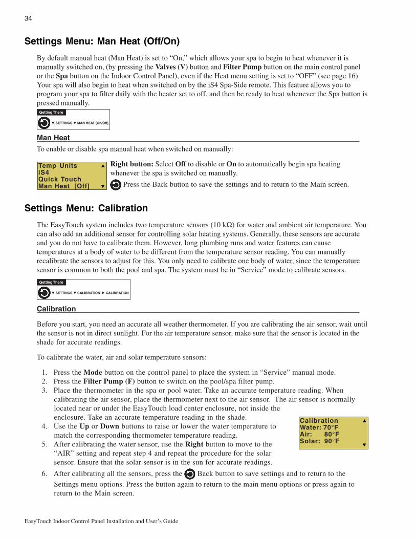
34
EasyTouch Indoor Control Panel Installation and User’s Guide
Settings Menu: Man Heat (Off/On)
By default manual heat (Man Heat) is set to “On,” which allows your spa to begin to heat whenever it ismanually switched on, (by pressing the Valves (V) button and Filter Pump button on the main control panelor the Spa button on the Indoor Control Panel), even if the Heat menu setting is set to “OFF” (see page 16).Your spa will also begin to heat when switched on by the iS4 Spa-Side remote. This feature allows you toprogram your spa to filter daily with the heater set to off, and then be ready to heat whenever the Spa button ispressed manually.
Man HeatTo enable or disable spa manual heat when switched on manually:
Right button: Select Off to disable or On to automatically begin spa heatingwhenever the spa is switched on manually.
Press the Back button to save the settings and to return to the Main screen.
Settings Menu: Calibration
The EasyTouch system includes two temperature sensors (10 kΩ) for water and ambient air temperature. Youcan also add an additional sensor for controlling solar heating systems. Generally, these sensors are accurateand you do not have to calibrate them. However, long plumbing runs and water features can causetemperatures at a body of water to be different from the temperature sensor reading. You can manuallyrecalibrate the sensors to adjust for this. You only need to calibrate one body of water, since the temperaturesensor is common to both the pool and spa. The system must be in “Service” mode to calibrate sensors.
Calibration
Before you start, you need an accurate all weather thermometer. If you are calibrating the air sensor, wait untilthe sensor is not in direct sunlight. For the air temperature sensor, make sure that the sensor is located in theshade for accurate readings.
To calibrate the water, air and solar temperature sensors:
1. Press the Mode button on the control panel to place the system in “Service” manual mode.2. Press the Filter Pump (F) button to switch on the pool/spa filter pump.3. Place the thermometer in the spa or pool water. Take an accurate temperature reading. When
calibrating the air sensor, place the thermometer next to the air sensor. The air sensor is normallylocated near or under the EasyTouch load center enclosure, not inside theenclosure. Take an accurate temperature reading in the shade.
4. Use the Up or Down buttons to raise or lower the water temperature tomatch the corresponding thermometer temperature reading.
5. After calibrating the water sensor, use the Right button to move to the“AIR” setting and repeat step 4 and repeat the procedure for the solarsensor. Ensure that the solar sensor is in the sun for accurate readings.
6. After calibrating all the sensors, press the Back button to save settings and to return to the
Settings menu options. Press the button again to return to the main menu options or press again toreturn to the Main screen.
▼ SETTINGS ▼ CALIBRATION CALIBRATION
Getting There
▲
CalibrationWater: 70°FAir: 80°FSolar: 90°F
Temp UnitsiS4Quick TouchMan Heat [Off]
▼ SETTINGS ▼ MAN HEAT [On/Off]
Getting There
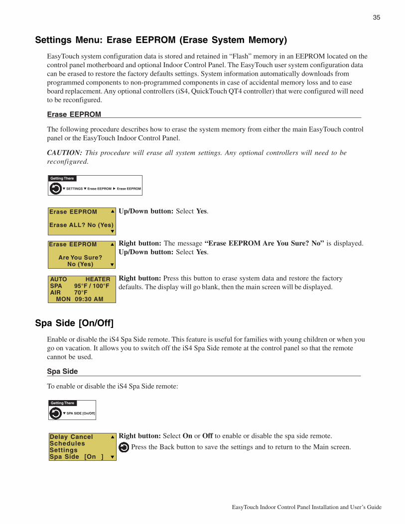
35
EasyTouch Indoor Control Panel Installation and User’s Guide
Settings Menu: Erase EEPROM (Erase System Memory)
EasyTouch system configuration data is stored and retained in “Flash” memory in an EEPROM located on thecontrol panel motherboard and optional Indoor Control Panel. The EasyTouch user system configuration datacan be erased to restore the factory defaults settings. System information automatically downloads fromprogrammed components to non-programmed components in case of accidental memory loss and to easeboard replacement. Any optional controllers (iS4, QuickTouch QT4 controller) that were configured will needto be reconfigured.
Erase EEPROM
The following procedure describes how to erase the system memory from either the main EasyTouch controlpanel or the EasyTouch Indoor Control Panel.
CAUTION: This procedure will erase all system settings. Any optional controllers will need to bereconfigured.
Up/Down button: Select Yes.
Right button: The message “Erase EEPROM Are You Sure? No” is displayed.Up/Down button: Select Yes.
Right button: Press this button to erase system data and restore the factorydefaults. The display will go blank, then the main screen will be displayed.
Spa Side [On/Off]
Enable or disable the iS4 Spa Side remote. This feature is useful for families with young children or when yougo on vacation. It allows you to switch off the iS4 Spa Side remote at the control panel so that the remotecannot be used.
Spa Side
To enable or disable the iS4 Spa Side remote:
Right button: Select On or Off to enable or disable the spa side remote.
Press the Back button to save the settings and to return to the Main screen.
▼ SETTINGS ▼ Erase EEPROM Erase EEPROM
Getting There
▲
Erase EEPROM
Erase ALL? No (Yes)
Erase EEPROM
Are You Sure? No (Yes)
AUTO HEATERSPA 95°F / 100°FAIR 70°F MON 09:30 AM
▼ SPA SIDE [On/Off]
Getting There
Delay CancelSchedulesSettingsSpa Side [On ]
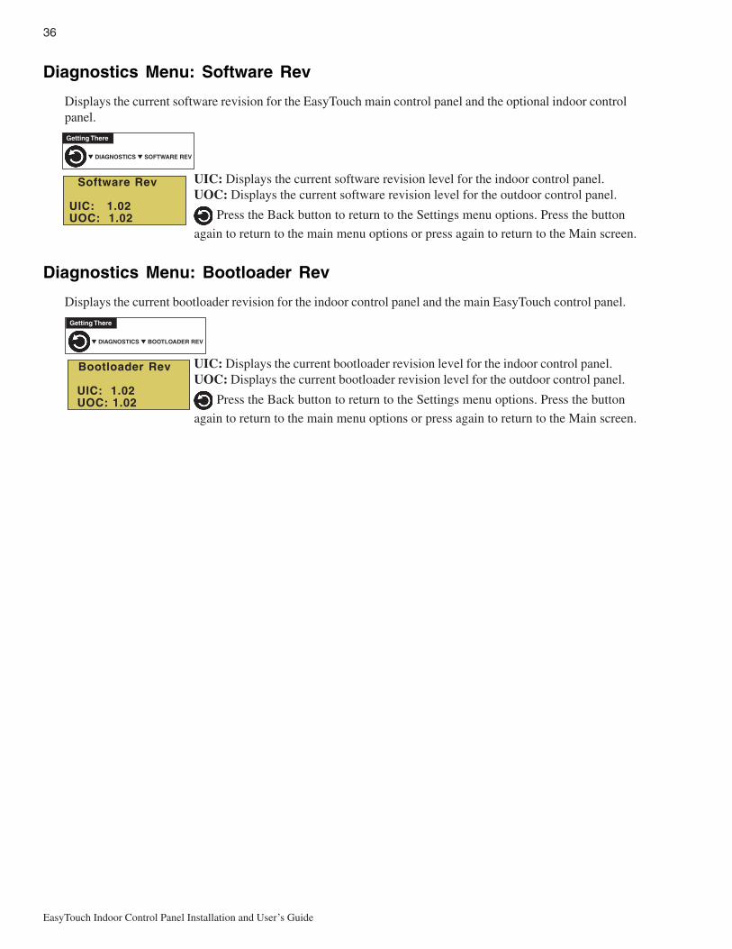
36
EasyTouch Indoor Control Panel Installation and User’s Guide
Diagnostics Menu: Software Rev
Displays the current software revision for the EasyTouch main control panel and the optional indoor controlpanel.
UIC: Displays the current software revision level for the indoor control panel.UOC: Displays the current software revision level for the outdoor control panel.
Press the Back button to return to the Settings menu options. Press the button
again to return to the main menu options or press again to return to the Main screen.
Diagnostics Menu: Bootloader Rev
Displays the current bootloader revision for the indoor control panel and the main EasyTouch control panel.
UIC: Displays the current bootloader revision level for the indoor control panel.UOC: Displays the current bootloader revision level for the outdoor control panel.
Press the Back button to return to the Settings menu options. Press the button
again to return to the main menu options or press again to return to the Main screen.
▼ DIAGNOSTICS ▼ SOFTWARE REV
Getting There
▼ DIAGNOSTICS ▼ BOOTLOADER REV
Getting There
Bootloader Rev
UIC: 1.02 UOC: 1.02
Software Rev
UIC: 1.02 UOC: 1.02

37
EasyTouch Indoor Control Panel Installation and User’s Guide
Diagnostics Menu: Self TestTests the control panel LCD and buttons. Follow the on-screen prompts to perform the tests.
Note: If the Indoor Control Panel is connected to the EasyTouch outdoor control panel, select “LINKCLOSED” in the UART test to abort the UART test. This allows the test to complete with and displayPASSED.
Press the Right button to display the current software and bootloader revision levelsfor the EasyTouch indoor control panel.
Press the Right button to start the test:
Display Test: Press any button to start the LCD test.
Backlight Test: Press the Left then Right button.
Contrast Test: Press any button to continue.
LED Test: Press any button to continue. All of the button LEDs will be tested.
Switch Test: Press any button to continue. As prompted, press the appropriatebuttons.
UART Test: Select “LINK CLOSED” to abort this test if the optional IndoorControl Panel is connected to the EasyTouch load center.
Status: Passed - Code: None After you have completed the test an error code isdisplayed. If the test was successful, “Passed” is displayed. For error codedescriptions, see “Self Test Error Codes,” on page 40.
Press the Back button to return to the Settings menu options. Press the button
again to return to the main menu options or press again to return to the Main screen.
▼ DIAGNOSTICS ▼ SELF TEST
Getting There
Backlight On<=Backlight On>=Backlight Off
Contrast:
Press any button
LED Test
Switch Test
Press any button
UART Test<=Link Closed>=Link Open
Press Any Button
EasyTouch 8Soft: 1.02Boot: 1.02Press Any Button

38
EasyTouch Indoor Control Panel Installation and User’s Guide
Diagnostics Menu: Chlorinator
Displays the current IntelliChlor chlorination system status. For more information, refer to the IntelliChlorElectronic Chlorine Generator User’s Guide (P/N 520589).
Press the Back button to return to the Settings menu options. Press the button
again to return to the main menu options or press again to return to the Main screen.
SALT LEVEL: Displays the current salt level. Values from 0 to 12750 ppm in 50 ppmincrements.IntelliChlor Status messages:
SUPER CHLORINATE: IntelliChlor is in “Super Chlorination mode (see page 24 fordetails)COM LINK ERROR: Check cable from IntelliChlor to EasyTouch motherboard.Check FLOW/PCB: Check IntelliChlor electrolytic cell controller. Refer to IntelliChlorUser’s Guide troubleshooting information.LOW SALT: Add salt to pool water. The water salt level is between 2500 ppm and2900 ppm. The IntelliChlor will continue to produce chlorine at a reduced level.VERY LOW SALT: Not enough salt in pool. The water salt level has fallen below 2500parts per million (ppm). IntelliChlor will not produce chlorine until additional salt isadded manually.HIGH CURRENT: Check IntelliChlor electrolytic cell controller. Refer to IntelliChlorUser’s Guide troubleshooting information..CLEAN CELL!!: Cell has calcium build up and requires cleaning. Refer to IntelliChlorUser’s Guide for cleaning instructions.LOW VOLTAGE: Check IntelliChlor electrolytic cell controller. Refer to IntelliChlorUser’s Guide troubleshooting information.OK - NO ERRORS: IntelliChlor is in normal operating mode.
Diagnostics Menu: Water TempDisplays the current water temperature for the pool and spa.
Press the Back button to return to the Settings menu options. Press the button
again to return to the main menu options or press again to return to the Main screen.
Diagnostics Menu: Solar TempDisplays the current temperature.
Press the Back button to return to the Settings menu options. Press the button
again to return to the main menu options or press again to return to the Main screen.
▼ DIAGNOSTICS ▼ WATER TEMP
Getting There
▼ DIAGNOSTICS ▼ SOLAR TEMP
Getting There
▼ DIAGNOSTICS ▼ CHLORINATOR
Getting There
ChlorinatorSalt Level:3200ppmStatus:[OK-NO ERRORS]
Water Temperature
75° F
Solar Temperature
85° F

39
EasyTouch Indoor Control Panel Installation and User’s Guide
Diagnostics Menu: Air Temp
Displays the current outside air temperature.
Press the Back button to return to the Settings menu options. Press the button
again to return to the main menu options or press again to return to the Main screen.
Diagnostics Menu: Disp Codes
Perform a communications test with installed equipment. Use this feature when testing the system.
To start the test:
Down button: Select Yes to enable the feature.
or Right button: Press either of these buttons to start communications test.
Digits display on the right side of all menu screens indicating verification transmit andreceived packets.
To stop test: Go to the “Disp Op Codes” menu and select No, then press the
back button to exit.
Diagnostics Menu: Cir Names: [Off/On]
This feature is useful if you have renamed many circuits and want to view the original factory default circuitnames.
To enable:
Right button: Select On to view the factory default circuit names.
Press the Back button to exit.
To disable:
Right button: Select Off to disable the feature.
Press the Back button to exit.
Diagnostics Menu: Reset System
Reset the Indoor Control Panel. Resetting the Indoor Control Panel will not affect the stored systemconfiguration settings.
Right button: Press the Right button to reset system. The main screen will bedisplayed and communication will be established with the EasyTouch outdoor controlpanel at the pool equipment pad.
▼ DIAGNOSTICS ▼ AIR TEMP
Getting There
Air Temperature
72° F
Disp Op Codes
Display? No
Solar Temp Air Temp Disp codes Cir Names [Off]
▼ DIAGNOSTICS ▼ CIR NAMES
Getting There
[Off]
▼ DIAGNOSTICS ▼ DISP CODES
Getting There
Air Temp Disp codes Cir Names [Off] Reset System
▼ DIAGNOSTICS ▼ RESET SYSTEM
Getting There

40
EasyTouch Indoor Control Panel Installation and User’s Guide
Diagnostics Menu: Flash Update
Use this feature to update the EasyTouch wireless control panel firmware. The unit must be connected to apersonal computer (PC) in order to update the firmware.
Press to exit the flash mode.▼ DIAGNOSTICS ▼ FLASH UPDATE
Getting There

41
EasyTouch Indoor Control Panel Installation and User’s Guide
Section 3Troubleshooting
Troubleshooting
Use the following troubleshooting information to help resolve problems that may occur when using theEasyTouch system. If by following the recommended actions you are still unable to resolve the problems,please contact Technical Support (see page vi).
Frequently Asked Questions (FAQ)
How do I setup a two-speed pump?
A two-speed pump operates using two relays and one or more circuits. The first relay turns the pump on oroff. Assuming this is a filter pump, this circuit is controlled by the pool and spa circuits or any other circuit thatmay be tied to the filter pump (such as circuits with freeze protection, etc.). The second relay switches thepump from low speed to high speed. The default condition is low speed. Up to seven circuits (EasyTouch 8),three circuits (EasyTouch 4) may be assigned to trigger the pump to high speed. Note: These circuits do notswitch the pump on.
To configure a two-speed pump relay, refer to “Settings Menu: 2-Speed Pump,” on page 30. The 2-Speedpump relay connector is plugged into the 2-SPD output on the EasyTouch motherboard.
Can I switch the heater on and change the temperature from the spa?
The heater may be switched on from the spa location using the iS4 Spa-Side remote or by the QuickTouchwireless remote controller. To learn more about these remotes and controllers, see page 6. However, the iS4and QuickTouch wireless remote controller cannot adjust the water temperature.
How do I switch on solar heating?
The system must first be configured for solar heating. Go to the “Heat” menu (see page 16) and enable“Solar” as the heat source (Settings Menu: Heat > Solar). Note: Do not set solar as a heat pump. Then theheating method must be selected for each body of water.
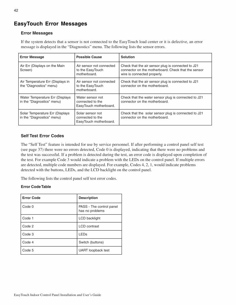
42
EasyTouch Indoor Control Panel Installation and User’s Guide
egasseMrorrE esuaCelbissoP noituloS
niaMehtnosyalpsiD(rrEriA)neercS
detcennoctonrosnesriAhcuoTysaEehtot
.draobrehtom
12JotdetcennocsigulprosnesriaehttahtkcehCrosnesehttahtkcehC.draobrehtomehtnorotcennoc
.ylreporpdetcennocsieriw
nisyalpsiD(rrEerutarepmeTriA)unem"scitsongaiD"eht
detcennoctonrosnesriAhcuoTysaEehtot
.draobrehtom
12JotdetcennocsigulprosnesriaehttahtkcehC.draobrehtomehtnorotcennoc
syalpsiD(rrEerutarepmeTretaW)unem"scitsongaiD"ehtni
tonrosnesretaWehtotdetcennoc
.draobrehtomhcuoTysaE
12JotdetcennocsigulprosnesretawehttahtkcehC.draobrehtomehtnorotcennoc
syalpsiD(rrEerutarepmeTraloS)unem"scitsongaiD"ehtni
tonrosnesraloSehtotdetcennoc
.draobrehtomhcuoTysaE
12JotdetcennocsigulprosnesralosehttahtkcehC.draobrehtomehtnorotcennoc
edoCrorrE noitpircseD
0edoC lenaplortnocehT-SSAPsmelborponsah
1edoC thgilkcabDCL
2edoC tsartnocDCL
3edoC sDEL
4edoC )snottub(hctiwS
5edoC tsetkcabpoolTRAU
EasyTouch Error Messages
Error Messages
If the system detects that a sensor is not connected to the EasyTouch load center or it is defective, an errormessage is displayed in the “Diagnostics” menu. The following lists the sensor errors.
Self Test Error Codes
The “Self Test” feature is intended for use by service personnel. If after performing a control panel self test(see page 37) there were no errors detected, Code 0 is displayed, indicating that there were no problems andthe test was successful. If a problem is detected during the test, an error code is displayed upon completion ofthe test. For example Code 3 would indicate a problem with the LEDs on the control panel. If multiple errorsare detected, multiple code numbers are displayed. For example, Codes 4, 2, 1, would indicate problemsdetected with the buttons, LEDs, and the LCD backlight on the control panel.
The following lists the control panel self test error codes.
Error Code Table
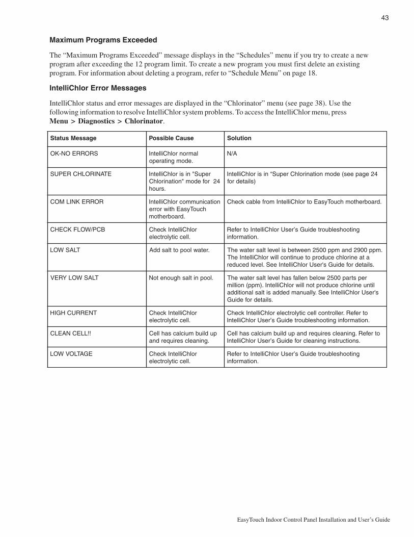
43
EasyTouch Indoor Control Panel Installation and User’s Guide
egasseMsutatS esuaCelbissoP noituloS
SRORREON-KO lamronrolhCilletnI.edomgnitarepo
A/N
ETANIROLHCREPUS repuS"nisirolhCilletnI42rofedom"noitanirolhC
.sruoh
42egapees(edomnoitanirolhCrepuS“nisirolhCilletnI)sliatedrof
RORREKNILMOC noitacinummocrolhCilletnIhcuoTysaEhtiwrorre
.draobrehtom
.draobrehtomhcuoTysaEotrolhCilletnImorfelbackcehC
BCP/WOLFKCEHC rolhCilletnIkcehC.lleccitylortcele
gnitoohselbuortediuGs’resUrolhCilletnIotrefeR.noitamrofni
TLASWOL .retawloopottlasddA .mpp0092dnampp0052neewtebsileveltlasretawehTataenirolhcecudorpoteunitnoclliwrolhCilletnIehT
.sliatedrofediuGs'resUrolhCilletnIeeS.leveldecuder
TLASWOLYREV .loopnitlashguonetoN repstrap0052wolebnellafsahleveltlasretawehTlitnuenirolhcecudorptonlliwrolhCilletnI.)mpp(noillims'resUrolhCilletnIeeS.yllaunamdeddasitlaslanoitidda
.sliatedrofediuG
TNERRUCHGIH rolhCilletnIkcehC.lleccitylortcele
otrefeR.rellortnoclleccitylortcelerolhCilletnIkcehC.noitamrofnignitoohselbuortediuGs’resUrolhCilletnI
!!LLECNAELC pudliubmuiclacsahlleC.gninaelcseriuqerdna
otrefeR.gninaelcseriuqerdnapudliubmuiclacsahlleC.snoitcurtsnigninaelcrofediuGs’resUrolhCilletnI
EGATLOVWOL rolhCilletnIkcehC.lleccitylortcele
gnitoohselbuortediuGs’resUrolhCilletnIotrefeR.noitamrofni
Maximum Programs Exceeded
The “Maximum Programs Exceeded” message displays in the “Schedules” menu if you try to create a newprogram after exceeding the 12 program limit. To create a new program you must first delete an existingprogram. For information about deleting a program, refer to “Schedule Menu” on page 18.
IntelliChlor Error Messages
IntelliChlor status and error messages are displayed in the “Chlorinator” menu (see page 38). Use thefollowing information to resolve IntelliChlor system problems. To access the IntelliChlor menu, pressMenu > Diagnostics > Chlorinator.

44
EasyTouch Indoor Control Panel Installation and User’s Guide
Problem: iS4 fails to operate.
motpmyS esuaCelbissoP noituloS
.tnempiuqeetarepootsliaf4Si .delbasidsi4Si .4Siehtelbaneot53egapeeS
gniriWevitcefeD ehtsahnoitseuqni4SiehterusnE.putes4SiyfireVotdengissatonsidna,stnemngissatiucricdetcepxe
.stiucricdesunu
ronoitarugifnoctcerrocnI.putesnottub
.snottub4Siehtputesot23egapeeS
4SievitcefeD 4SievitcefedecalpeR
foemosylnoetarepootsliaf4Si.enifkrowsrehtotub,sehctiwseht
roenonogniriwevitcefeDsdael4Sierom
.4SidnadraobrehtomnogniriwyfireV
ronoitarugifnoctcerrocnIhctiwsottiucric
.tnemngissa
.noitcennocdraobrehtomyfireV
System Problem Diagnosis
Use the following information to resolve system problems.
Problem: The system works in Service Mode, but Indoor Control Panel fails to operate.
motpmyS esuaCelbissoP noituloS
onsahlenaPlortnoCroodnI,sDELon,knalb,neercs(-rewop
.)gnikrowtonsnottub
morfnurgniriwdaBlortnoCroodtuO
ehtnidraobrehtom/lenaP.retneCdaoL
nI.nekorberasnoitcennoconerusnednaelbacyfireVehT.noitalusniehtrednunekorbsieriwasesacemos
tcepsuseraelbacrotcudnocruofehtfoseriwretnecowt)wolleYdnaneerG(
tub,pusthgillenaPlortnoCroodnItinuehT.yltcerrocetarepootsliaf
ro,ffo/notnempiuqenruttonlliwtontub,nosmetiemosnrutyam
raensDELtonyamdnaffo.lenaplortnocnosnottub
gniriw/elbaCevitcefeD yfireV elbac nI.nekorberasnoitcennoconerusnednaehT.noitalusniehtrednunekorbsieriwasesacemos
tcepsuseraelbacrotcudnocruofehtfoseriwretnecowt)wolleYdnaneerG(

45
EasyTouch Indoor Control Panel Installation and User’s Guide
Problem: The Quick Touch remote will not work, or will not work dependably.
motpmyS esuaCelbissoP noituloS
nothgiltonseodDELREWOPehtnidetacoldraobrevieceReht
.llehsmalccitsalp
retneCdaoLhcuoTysaErewopevahtonseod
rewopehttahtdnadeilppusgniebsirewoperusnEdellatsnireviecerehttuohtiwyltcerrocsetareporetnec
roelbacevitcefeDdaoLehtotnoitcennoc
retneC
elbacdoognwonkgnisudraobehtfonoitcnufehtyfireVgniriwllakcehC.tes
draobrevieceRevitcefeD troppuSlacinhceTtcatnoC
thgiltonseodDELKNILMMOCDELnoitarepolamronnI.knilbrosdnoces2yrevetsaeltaknilblliw
roelbacevitcefeDdaoLehtotnoitcennoc
retneC
elbacdoognwonkgnisudraobehtfonoitcnufehtyfireVtes
draobreviecerevitcefeD draobreviecerecalpeR
yltcerrocnierasehctiwssserddAderugifnoc
sserddaehttahtyfireVehtnosehctiws
dlehdnahdnarettimsnarttcerroceradraobreviecer
hctamdna
deliafsahyrettabrettimsnarT
rettimsnarTecalpeRyrettab
revieceRrorettimsnarTevitcefeD
emostub,snoitcnuftinUro,krowtonodstiucric
tcerrocniehtetarepotiucric
tcerrocnisinoitarugifnochcuoTkciuQ
stiucricemostub,snoitcnuftinUehtetareporo,krowtonod
tiucrictcerrocni
noitarugifnochcuoTkciuQtcerrocnisi
snottubputesot23egapeeStaylbadnepedetarepootsliafro,etarepootsliaftinU
egnar
otsliafro,etarepootsliaftinUegnartaylbadnepedetarepo
esionlacirtceleevissecxE lacirtcele""ysion""morfyawareviecerehtetacoleRsrotomrewolbsahcustnempiuqe
snoitcurtsboynamooTrettimsnartehtneewteb
reviecerdna
dnalatemdnuorgmorfyawareviecerehtetacoleRsnoitcurtsbo
raenootsitinurevieceRdnuorgeht
neewtebecnatsidehtezimixamotreviecerehtetacoleRdnuorgehtdnaannetnareviecereht

46
EasyTouch Indoor Control Panel Installation and User’s Guide
motpmyS esuaCelbissoP noituloS
fforononrutotsmeestinU/resuehttuohtiwstiucric
rettimsnart
siemohybraenAralimisagnitarepo
tinusseleriw
dnarettimsnartehtrofedocsserddaetanretlanatceleSdnareviecerhtobnosehctiwsehtegnahC.reviecer
.gnittesgnihctamtub,etanretlanaotetomer
tnempiuqesnrutylbadnepedtinUsitnempiuqeecnotub,NO
ylbadnepedtonseodtigninnursiegnarro,FFOtnempiuqenrut
tnempiuqenehwdecuderyltaerggninnursi
siesionlacirtceleeudnUroenoybdecudorpgniebtnempiuqefoseceiperom
ehtotytimixorpesolcni.reviecer
sahcustnempiuqemorfyawarevieceRehtetacoleRtahtnoitacolanirevieceRehtetacoleRsrotomrewolb
resuehtaeraehtotsnoitcurtsborewefsedivorp.rettimsnartehtsetarepoylnommoc
yltaergsahtub,setarepotinUroirpotderapmocegnardecuder
noitcnuf
siyrettaBrettimsnarT.gniliaf
.)V32302epyt(yrettabrettimsnarTecalpeR
Problem: The Quick Touch remote will not work, or will not work dependably (Continued).
Synchronizing control panels
If the EasyTouch outdoor has been previously setup with specific pool and spa information and you install theEasyTouch indoor control panel with factory default information, the outdoor control panel will automaticallydownload the existing system information to the indoor control panel. If the indoor control panel has a differentfirmware revision level than the outdoor control panel or it contains previous setup information, you can choosewhich system image to upload or download.
Synchronizing the control panels is initiated from the indoor control panel. The following describes how tosynchronize the indoor control panel with the outdoor control panel.
Download from outdoor to indoor control panel
• Press the Menu button to download the system image from the EasyTouch outdoor control panelto the indoor control panel.
Upload to outdoor from indoor control panel
1. Press the Up/Down button to access the “Upload” screen.
2. Press the Menu button to upload the system image from the indoor control panel to theEasyTouch outdoor control panel.
Note: To erase existing control panel system information, use the “Erase EEPROM” feature.Refer to “Erase EEPROM” on page 35 for more information.
Unit Mismatch Download from Outdoor
Unit Mismatch Upload to Outdoor

47
EasyTouch Indoor Control Panel Installation and User’s Guide
Section 4EasyTouch Indoor Control Panel Installation
Installing the EasyTouch Indoor Control Panel
Use the following procedure to install the EasyTouch Indoor Control Panel. Read through the installationprocedure before starting.
The EasyTouch indoor control panel provided one touch controls for your pool, spa, lights and other functionsfrom inside your home or a sheltered location. Select a convenient wall location inside your the house or otherweather-protected location for mounting the control panel.
Drill control panel wall mounting holes
To drill the control panel mounting holes:
1. The control panel is 5 ¾” wide. Using the cutout template (shown on the following page), mark thetwo screw locations on the wall for the mounting holes. Drill the two mounting holes. If the screwsare not being screwed into studs, drill 3/16” holes and insert wall anchors as required.
2. Drill a 1 inch hole in the area shown in the template for the communication cable to feed through.

48
EasyTouch Indoor Control Panel Installation and User’s Guide
EasyTouch Indoor Control Panel Template
EasyTouch Indoor Control Panel Cut-Out Template
Cut out template along dotted lines.C
ut-o
ut H
ere C
ut-out Here
Edge of Control Panel
Edge of Control Panel
3/16" Hole for Plastic Anchor
3/16" Hole for Plastic Anchor
DRILL HOLE FOR COMMUNICATION CABLE
HERE

49
EasyTouch Indoor Control Panel Installation and User’s Guide
Cabling the Indoor Control Panel at the Load Center
To connect the indoor control panel cable to the motherboard:
1. Turn off the main system power before making any connections.
2. Run a UL approved four conductor cable (22 AWG) from the indoor control panel to the LoadCenter. The preferred wire color scheme is: Red, yellow, green, and black.
3. Route the cable up through the low voltage raceway to the motherboard.
4. Strip back the communication cable conductors ¼ in. Insert the wires into the screw terminals(provided in the kit). Secure the wires with the screws. Make sure to match the color-coding of thewires: Red = +15, Yellow = +DT, Green = -DT, and GND = Black.
5. Insert the cable plug onto the COM-PORT (J20) connector.
6. Proceed with Mount and Cable the Indoor Control Panel, page 50.
COM PORT(J20)
Indoor Control PanelIntelliChlorIntelliFloRF Transceiver
EasyTouch Motherboard

50
EasyTouch Indoor Control Panel Installation and User’s Guide
Mount and Cable the EasyTouch Indoor Control Panel
To mount and connect the communication cable to the EasyTouch Indoor Control Panel:
1. Route the cable through the house wall to the location of the indoor control panel. Pull a workinglength of the communication cable out of the wall.
2. Remove the control panel front cover from the back plate: Unsnap the bottom edge of the frontof the control panel cover from the back plate.
Front cover
Back plate
Mounting hole
Hole in house wall forcommunication cable
Mounting holeUnsnap from here toremove front cover
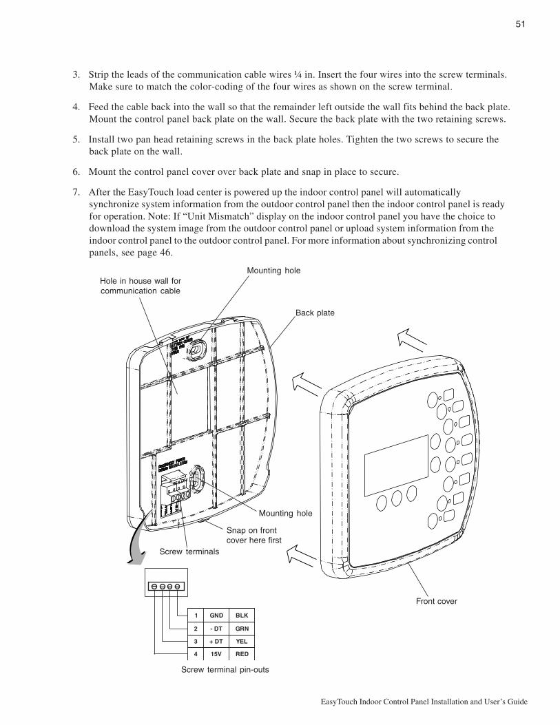
51
EasyTouch Indoor Control Panel Installation and User’s Guide
3. Strip the leads of the communication cable wires ¼ in. Insert the four wires into the screw terminals.Make sure to match the color-coding of the four wires as shown on the screw terminal.
4. Feed the cable back into the wall so that the remainder left outside the wall fits behind the back plate.Mount the control panel back plate on the wall. Secure the back plate with the two retaining screws.
5. Install two pan head retaining screws in the back plate holes. Tighten the two screws to secure theback plate on the wall.
6. Mount the control panel cover over back plate and snap in place to secure.
7. After the EasyTouch load center is powered up the indoor control panel will automaticallysynchronize system information from the outdoor control panel then the indoor control panel is readyfor operation. Note: If “Unit Mismatch” display on the indoor control panel you have the choice todownload the system image from the outdoor control panel or upload system information from theindoor control panel to the outdoor control panel. For more information about synchronizing controlpanels, see page 46.
Screw terminal pin-outs
Screw terminals
1 DNG KLB
2 TD- NRG
3 TD+ LEY
4 V51 DER
Front cover
Back plate
Mounting holeHole in house wall forcommunication cable
Mounting hole
Snap on frontcover here first

52
EasyTouch Indoor Control Panel Installation and User’s Guide
Glossary
Aux Extra: An additional auxiliary output circuit that uses the Solar socket (J17) on the EasyTouchmotherboard. Uses the Down arrow button on the indoor control panel to switch circuit on and off. Onlyavailable if solar equipment is not being used.
High Voltage Compartment: Large lower right compartment of Load Center for all high voltage wiringincluding circuit breakers, relays, and GFCI.
Indoor Control Panel: Nine or 14 button remote controller with LCD (liquid crystal display) wired to theEasyTouch motherboard in the load center. The Indoor control panel can be wall mounted inside the house.
iS4: Four function Spa-Side remote. Can be spa wall or deck mounted.
Load Center: Metal enclosure with power relays, transformer, and circuit breakers. Used for distributingpower for controlling the EasyTouch system. Also known as the “sub-panel.”
Low Voltage Compartment: Top compartment of Load Center for all low voltage wiring.
Low Voltage Raceway: Vertical space in the left side of EasyTouch load center for low voltage cabling.
Indoor Control Panel: EasyTouch control panel with flexible hinge installed in upper portion of EasyTouchLoad Center to control the EasyTouch system.
Motherboard: The circuit board mounted on top of the EasyTouch control panel. The EasyTouchmotherboard defines the system capabilities.
Receiver/Antenna: Used with the QuickTouch (QT4) to receive radio frequency (wireless) transmissions.
RF Transceiver: Used with the EasyTouch wireless control panel to transmit and receive radio frequency(wireless) transmissions.
Relay Circuits: The circuits that control the relay outputs on the EasyTouch motherboard. Connectors arelocated on the top edge of the circuit board.
Screw Terminal Connector: Removable connector that may attach to circuit board with multiple sockets(anywhere from 2 to 12) to receive wires from controllers and sensors; wires held by screw terminals; multiplewires of a small enough gauge (usually 22 AWG) may be coupled to a single socket of a terminal connector.Sockets are located on the EasyTouch motherboard.

53
EasyTouch Indoor Control Panel Installation and User’s Guide
Note

54
EasyTouch Indoor Control Panel Installation and User’s Guide
Note


P/N 520617 Rev B