Embed Size (px)
Citation preview

Chapter 1Date 11/04/99, page 1
PROFIBUS
� What a fieldbus system needs to offer� deterministic (since parallel wiring will be replaced)
� flexible
� interoperable (multi-vendor use)
� cost effective (installation, startup, service)
� reliable and safe
� easy to use
� standardization
Chapter 1Date 11/04/99, page 2
EN 50170 Volume 2
Process Automation
PROFIBUS-PAIEC 1158-2
- Powering over the bus - Intrinsic safety
Factory Automation
PROFIBUS-DPRS 485 / FO
- Plug and play- Efficient and cost effective
Fast
General PurposeAutomation
PROFIBUS-FMSRS 485 / FO
- Large variety of applications- Multi-master communication
Universal Application Oriented
PROFIBUSEN 50170
Chapter 1Date 11/04/99, page 3
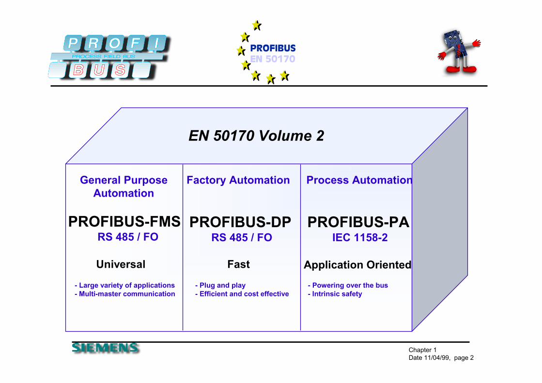
INTERNATIONAL� More than 900 members - 23 regional user associations
ChinaJapanKoreaSingapore
South AfricaAustriaBelgiumCzech RepublicDenmarkFinlandFranceGermanyIrelandItalyNetherlandsNorwayRussiaSwedenSwitzerlandUnited Kingdom
AfricaAfricaAmericaAmerica EuropeEurope AsiaAsia
PROFIBUS InternationalPROFIBUS International
BrazilUSA
*Status: Q3/1999
AustraliaNew Zealand
AustraliaAustralia

Chapter 1Date 11/04/99, page 4
PRODUCT VarietyDrives
AC Drives
DC Drives
Decentralized I/OBinary I/O
Analog I/O
Regulators
Timer
Counter
Ident-Systems
GatewaysAS-Interface
Proprietary networks
ToolsConfiguration
Bus Monitor
Engineering
Host Interfaces VAX computers
VME computers
Network components Repeaters
Fiber optics
Cables
Controllers PLC/NC/RC
VME, PC
Workstation
Software Drivers DOS/Windows/NT/95
RT-OS/OS9/VRTX
VxWorks/PSOS+
OS2, QNX
UNIX/VMS
ServicesDevelopment Support
Implementation Support
TrainingMMI
Operator Panels
Text DisplaysValvesPneumatic Valves
Magnetic Valves
InstrumentsLevel
Flow
Pressure
Temperature

Chapter 1Date 11/04/99, page 5
CNCPC/VME
VME/PCPLC DCS
AreaController
Ethernet/TCP/IP TCP/IP/Ethernet
PROFIBUS-FMS RS-485/FO
PROFIBUS-DP RS-485/FO PROFIBUS-PA IEC 1158-2
Factory level
Bus CycleTime
< 1000 ms
Cell Level
Bus CycleTime
< 100 ms
Field Level
Bus Cycle-Time
< 10 ms

Chapter 1Date 11/04/99, page 6
EN 50170 - 2
� The PROFIBUS Protocol is in Accordance with the ISO/OSI Reference Model for Open Systems
PA-ProfilesFMS
DeviceProfiles
FMS
IEC 1158-2
User
Laye
r
(3)-(6)
Application(7)
Data Link(2)
Physical(1)
not used
PA
EN 50 170 PROFIBUS guidelines + profiles
DP
DP-Extensions
DP-Profiles
RS-485 / Fiber Optic
DP Basic Functions
Fieldbus Data Link (FDL) IEC Interface
Fieldbus MessageSpecification
(page 14 in the binder)

Chapter 1Date 11/04/99, page 7
Bus Access
� The PROFIBUS Bus Access Method combines Multi-Master and Master-Slave communications
PROFIBUS
Active Stations, Master Devices
Passive Stations(Slave Devices) are polled
PLCPC

Chapter 1Date 11/04/99, page 8
Bus Access
� the PROFIBUS Bus Access Protocol (Layer 2) is identical for all three PROFIBUS variations
� this enables transparent communication and easy combinations of FMS/DP/PA Network sections
� Because FMS/DP use the same Physical Media (RS-485/FO), they can be combined on the same cable
Active Stations, Master Devices
PROFIBUS
PLCPLC PC

Chapter 1Date 11/04/99, page 9
Bus Access
� Hybrid Bus Access Protocol� Token-Passing between Masters
Master - Slave Protocol between Master and Slaves
� Master� active stations with the right to control the bus for a
limited amount of time (Token - Hold - Time)
� Slave� Slaves only respond on request of a Master -
they have no rights to control the bus
Chapter 1Date 11/04/99, page 10
Bus Access
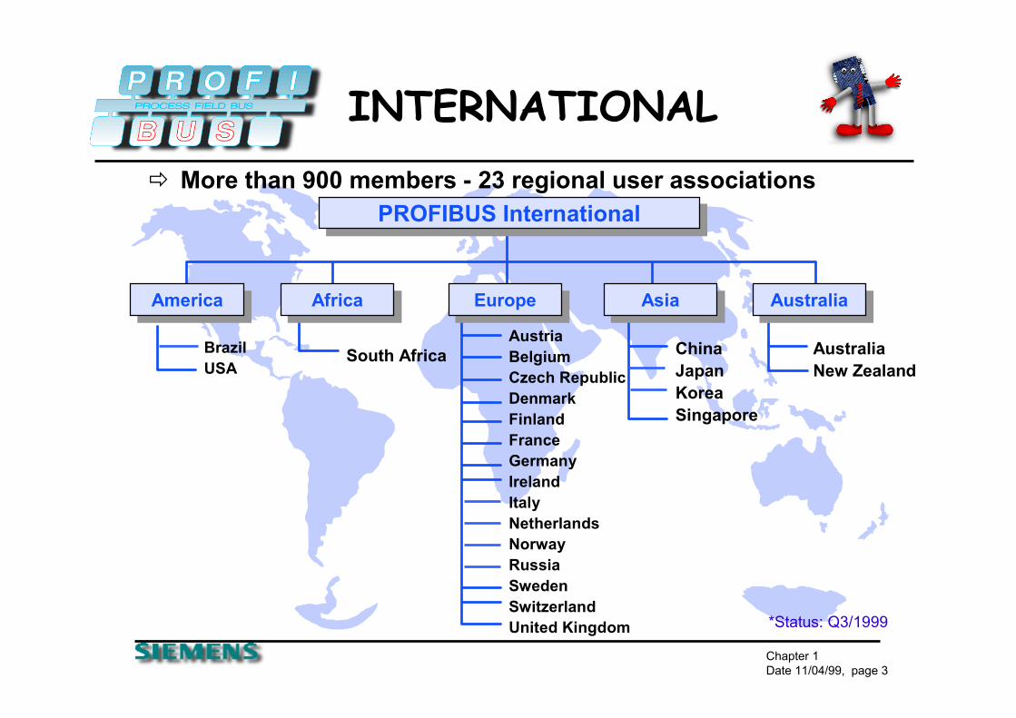
� in Multi-Master Networks, the Token Passing procedure must ensure that each master has enough time to fulfill its communication tasks
� the user therefore configures the overall Target Token Rotation Time (TTR) taking into account the communication tasks of all masters
� each Master calculates the available amount of time for its communication tasks at token receipt according to the following rule:
TTH = Token Hold TimeTTR = Target Token Rotation TimeTRR = Real Token Rotation Time
TTH = TTR - TRR
Chapter 1Date 11/04/99, page 11
FMS, DP, PA
� FMS stands for Fieldbus Messaging System� peer to peer communication
� DP stands for Decentralized Periphery� fast data exchange
� PA stands for Process Automation� intrinsically safe environment

Chapter 1Date 11/04/99, page 12
FMS/DP In Common
� DP and FMS are based on same Layer 1 and 2:� DP and FMS can be operated on the same bus
� Message header and data length are identical
� The bus physics are identical
� One master can service several slaves� Several masters can participate on the bus� Baudrates from 9.6 kBd up to 12 MBd are possible

Chapter 1Date 11/04/99, page 13
FMS/DP In Common
� Data transmission can be between 1 and 244 bytes� 126 stations can be connected� System can consist of several segments� 32 stations (RS 485 drivers) per segment� Common components� Cabling, connectors, repeater, fibre optic
� Savings in maintenance and spare parts inventory

Chapter 1Date 11/04/99, page 14
PA/DP In Common
� DP and PA are based on the same protocol definition - DP/V1 (extended DP)� DP and PA can use the same master systems
� Message header and data length are identical
� Configuration tools are the same
� Data transmission can be between 1 and 244 bytes

Chapter 1Date 11/04/99, page 15
PA/DP In Common
PROFIBUS-PA
PROFIBUS-DP, up to 12 Mbit/s
PLC or PC with PROFIBUS
DP-Slave
DP/AS-ilink
Actuator/Sensor interface
24 VDP/PA coupler,
DP/PA link
PA - 31.25 kBd

Chapter 1Date 11/04/99, page 16
FMS Features
� FMS is optimized for universal, object oriented communication of intelligent master devices at the cell level
� FMS permits a subset of the MMS-Functions (Manufacturing Message Specification, ISO 9506)
� A slave can be assigned to several masters� Several masters can write to the same slave
� Communication connections can be temporary or permanent
� Communication is defined in a communication relation list

Chapter 1Date 11/04/99, page 17
FMS Services
� The FMS application layer (7) consists of the following parts: � The Fieldbus Message Specification (FMS) and
� the Lower Layer Interface (LLI)
� FMS services are a subset of the MMS services (MMS=Manufacturing Message Specification, ISO 9506) � have been optimized for field bus applications and have been
expanded by functions for communication object administration and network management

Chapter 1Date 11/04/99, page 18
FMS Servicesvirtual field device (VFD).
� The PROFIBUS-FMS communication model permits distributed application processes to be unified into a common process by using communication relationships. � The portion of an application process in a field device which can be
reached via communication is called a virtual field device (VFD)

Chapter 1Date 11/04/99, page 19
FMS Services
�Context Management services are for establishing and terminating logical connections.�Variable Access services are used to access variables, records, arrays or variable lists. �Domain Management services are used to transmit large memory areas. The data must be divided into segments by the user. �Program Invocation Management services are used for program control.�Event Management services are used to transmit alarm messages. These messages can also be sent as broadcast or multicast transmissions.�VFD Support services are used for identification and status polling. They can also be sent spontaneously at the request of a device as multicast or broadcast transmissions.�OD Management services are used for read and write access to the object dictionary.

Chapter 1Date 11/04/99, page 20
FMS Services
� Confirmed services can only be used for connection-oriented communication relationships. The execution of a service is shown in Figure
� Unconfirmed services can also be used on connectionless communication relationships (broadcast and multicast). They can be transmitted with high or low priority.

Chapter 1Date 11/04/99, page 21
FMS Features
� FMS access procedure
Slave 1 Slave 2 Slave 3 Slave x

Chapter 1Date 11/04/99, page 22
PA Features
� Based on the extended PROFIBUS-DP Protocol and IEC 1158-2 Transmission � Suitable to replace today's 4...20 mA Technology
� Only two wires for data and power
� Connects Instruments to the control system via a serial bus
� Functional improvements plus reliable serial digital transmission
� Control, regulation and monitoring via a simple twisted pair cable
� A single engineering tool for all devices
Chapter 1Date 11/04/99, page 23
PA Features
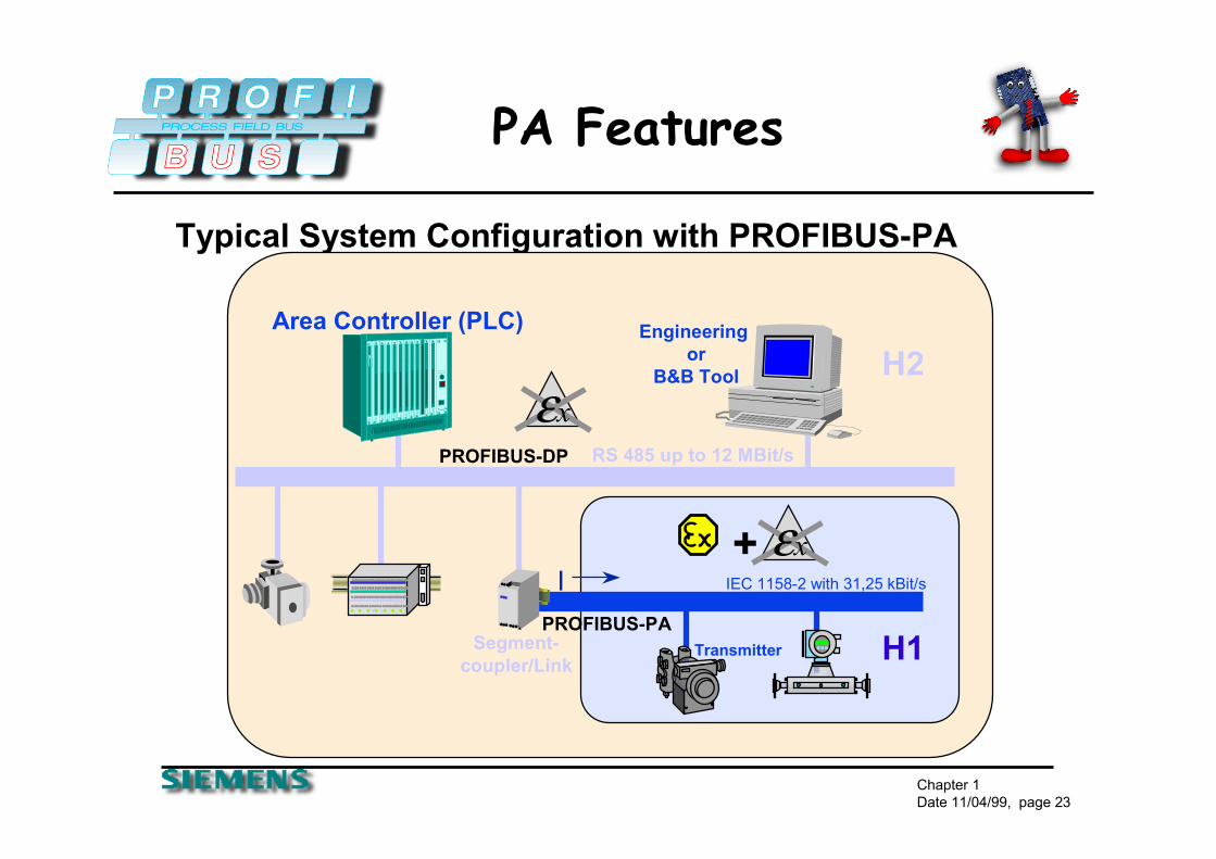
Typical System Configuration with PROFIBUS-PA
PROFIBUS-DP RS 485 up to 12 MBit/s
Area Controller (PLC) Engineering or
B&B Tool
PROFIBUS-PA
IEC 1158-2 with 31,25 kBit/sI
εx
Segment-coupler/Link
Transmitter
H2
H1
+ εx

Chapter 1Date 11/04/99, page 24
DP Features
� DP communication is permanent and cyclic � the transmitted data is specified during the
configuration (optimized data exchange)� only one master can write outputs (safety aspect)� data can be read by controlling and Class 2 master� acyclic data via DPV1 functions� alarm acknowledgment� fastest fieldbus system (up to 12 MBaud)� up to 244 byte input AND 244 byte output data per
station

Chapter 1Date 11/04/99, page 25
DP Features
� DP- Access Procedure
Slave 1 Slave 2 Slave 3 Slave x
Master - Token exchange
Class 2
Chapter 1Date 11/04/99, page 26
Reliability-DP/FMS
� Hamming Distance HD = 4� HD 4 means, that up to 3 transmission failures at a
time can be detected (done by the ASICs)� By detecting a faulty telegram, it will be resent
automatically without affecting other existing stations
� HD 4 is a term used to describe the reliability of the data transmission on the Profibus network.� Special Start and End Sentinels� Parity Bit for Each Byte� Slip Free� According to IEC 870-5-1� Delimiter Synchronization

Chapter 1Date 11/04/99, page 27
PROFIBUS Wiring
� PROFIBUS DP/FMS wiring can be done with:� twisted shielded pair copper cable
� fiber optic components
� infrared components
� detailed installation guideline is available PTO order no. 2.112

Chapter 1Date 11/04/99, page 28
PROFIBUS Wiring
� twisted shielded pair cable� line parameters are defined in EN 50170
� standard cable available from Belden and Siemens
� standard connectors availableBaudrate Max. Segment length Max. Expansion
9.6 1000m / 3278feet 10,000m / 32786feet19.2 1000m / 3278feet 10,000m / 32786feet
93.75 1000m / 3278feet 10,000m / 32786feet187.5 1000m / 3278feet 10,000m / 32786feet500.0 400m / 1311feet 4,000m / 13114feet
1,500.0 200m / 655feet 2,000m / 6557feet3,000.0 100m / 327feet 1,000m / 3270feet6,000.0 100m / 327feet 1,000m / 3270feet
12,000.0 100m / 327feet 1,000m / 3270feetmax. expansion is done with 9 repeaters in a row

Chapter 1Date 11/04/99, page 29
PROFIBUS Wiring
� fiber optic components� plastic and glass fiber optic is available
� optical plugs and modules are available
�noise immune
�potential difference independent� longer distances (up to 20 miles)
� redundant operating is possible� line, ring and star configuration

Chapter 1Date 11/04/99, page 30
PROFIBUS Wiring
� infrared components� wireless linking of devices in close-up ranges
� communication with moving devices
� communication with changing devices
� noise immune
� ground independent

Chapter 1Date 11/04/99, page 31
PROFIBUS Wiring
Several interfaces enableredundant systems
Fiber optic segmentsenable redundant wiring
Two devices per measuring point
FOcoupler
FOcoupler
FOcoupler
FOcoupler
System redundancy Media redundancy
� Redundancy Improves System Reliability

Chapter 1Date 11/04/99, page 32
DP Details
� class 1 master -� central controller which exchanges data with the
connected I/O devices (slaves)� determines the baudrate � handles the Token� several class1 masters are permitted, typical devices are
PLC, PC � class 2 master -� diagnostic and startup tool, typically a configuration tool� can control one slave at a time
� slave station -� passive station which acknowledges messages or answers
per request

Chapter 1Date 11/04/99, page 33
DP Details
� master- master, master- slave communication
Class 1 Master Class 2 Master
Slave
Reading DiagnosisParameter Assignment
ConfiguringData Exchange
Reading Diagnosis Parameter Assignment
Configuring Address ChangeReading Configuration
Reading I/OControlling of one Slave
Reading Slave Diagnosis,Upload, Download
Activating Bus Parameter. Download,Activating/,Deact. Slaves, Operating Mode
a device can consist of multiple functions, e.g.... class1 and class2, class1 and slave

Chapter 1Date 11/04/99, page 34
DP Details
� A device can consist of multiple functions, e.g... class1and class2, class1 and slave, which allows:
� a simple master master communication via the master -slave combination
� whenever one master has the token the other PLC can be a slave to this master
PLC PLCPLC1 - master and slave
PLC2 - master and slave

Chapter 1Date 11/04/99, page 35
DP Details
� Master - Master communication by using a DP-DP gateway
� combination of two mono master systems
� simple data exchange between the two masters up to 244 byte
PLC PLC

Chapter 1Date 11/04/99, page 36
Interoperability
� Open Configuration permits Plug and Play
PROFIBUS configuration tool
System configuration
Electronic Device Data Sheets (GSD-file)
PLC
PROFIBUS
GSD GSD GSD GSD GSD GSD

Chapter 1Date 11/04/99, page 37
Device Description
� GSD file
� each slave or master class 1 device on PROFIBUS DP needs to have a device description file, the characteristic of each PROFIBUS-DP device is described in the GSD-File
� the GSD-file contains all device specific parameters e.g.:� Supported Baudrate� Supported Message Length� Number of input / output data� Meaning of diagnostic messages� Options for modular devices e.g. which are available
� text file (ASCII-format)
� each configuration tool relates to the GSD information

Chapter 1Date 11/04/99, page 38
Device Description
� GSD-Files are created by the device vendors
� the PROFIBUS Trade Organization provides an GSD-Editorwhich makes it very easy to create GSD-Files
� the GSD-Editor contains a GSD-Checker which guarantees the conformance of the GSD-Files to the PROFIBUS standard
� a library of GSD-Files is provided at the PROFIBUS web page: http://www.profibus.com

Chapter 1Date 11/04/99, page 39
Device Description# P r o f ib u s _ D P ( M ):< P R M - T e x t_ D e f_ L is t> ( O )P r m T e x t =… … . .E n d P r m T E x t
;< E x t- U s e r _ P r m _ D a ta _ D e f_ L is t> ( O )E x tU s e r P r m D a ta =… … … .E n d E x tU s e r P r m D a ta
;< U n it_ D e f in it io n _ L is t> ( M )G S D _ R e v is io n = 1V e n d o r _ N a m e =… … . .… … .
;S la v e s p e c if ic d a ta ( M )F r e e z e _ m o d e _ s u p p o r te d =… … . .… …;U s e r _ P r m _ d a ta… … .;U n it_ d ia g n o s t ic… … . .
;< M o d u le _ D e f in it io n _ L is t ( M )M o d u le =… … .E n d M o d u le
Parameter text (O)
ext. user parameter data (O)
mandatory general data (M)
generic slave data (M)
device related slave data (O)
I/O definition (M)

Chapter 1Date 11/04/99, page 40
DP InteractionsDP Extended
� Why DP extended?
� the requirements of the process industry are included
� selecting and changing parameters of a field device from several DP-Masters, e.g.. CPU, PG or HMI Devices� provides for higher flexibility in operation
� Interrupts from Field Devices, e.g.. for diagnostics, have to be accepted by the DP-Master� allows for greater security
� time stamping of events, e.g.. for interrupts, accurate history of special events
� additional data formats are necessary for transmitting data, e.g.. floating-point-radix

Chapter 1Date 11/04/99, page 41
DP Extended
� every station that handles the DP-extensions must meet the previous PROFIBUS-DP-Standard-Functions!
DP-Extension• Additional acyclic messages between Master and Slaveby reading and writing of data blocks
• Acknowledgment of field device interrupts
• Time synchronization for an exact time stamping
• Extension of data types, floating-point-radix
PROFIBUS-DP-Standard !New
ext
ende
d PR
OFI
BU
S-D
P-St
anda
rd

Chapter 1Date 11/04/99, page 42
DP Extended
� Acyclic communication connections between Class 1 Master and Slave via Slave SAP 51
� Read data set (DDLM_Read)
� Write data set (DDLM_Write)
� Acknowledge alarms (DDLM_Alarm_Ack)
� Only the master that parameterized and configured the slave can utilize the SAP 51 for these services also
� Alarm can only be acknowledged by the Class 1 Master via SAP 51 (access protection)
Chapter 1Date 11/04/99, page 43
� Acyclic communication relations between Class 2 Master and Slave via SAP 0…49
� Initiate (MSAC2_Initiate) - SAP 49
� Abort (MSAC2_Abort)
� Read Data Set (MSAC2_Read)
� Write Data Set (MSAC2_Write)
� Data Transport (MSAC2_Data_Transport)
DP Extended

Chapter 1Date 11/04/99, page 44
Network Setup
class 1 master class 2 master
termination
termination

Chapter 1Date 11/04/99, page 45
PIC certification
• Vendor applies for an ID number from PROFIBUS International (PI)for his device
• Vendor develops the PROFIBUS device and writes a GSD file
Applies for Certification test at any PROFIBUS Test Lab
Test passed ?NO
YES
Vendor receives two test reports and can apply for a certificate via PI
refu
sed
CERTIFICATE
� How to certify a device!

Chapter 1Date 11/04/99, page 46
Profibus & Ethernet
� The PROFIBUS User Organization is currently working on the implementation of universal concepts for vertical integration on the basis of Ethernet TCP/IP

Chapter 1Date 11/04/99, page 47
PROFInet� Automation object model according to the Microsoft
COM/DCOM standard� Communication: TCP(UDP)/IP and DCOM wire protocol
devices
� Object handling in engineering and HMI: Microsoft OLE, ActiveX
� Integration of existing unchanged PROFIBUS bus segments and PROFIBUS based devices

Chapter 1Date 11/04/99, page 48